User’s Guide - Perle · Document Title .JETSTREAM 6x series, User’s Guide ... Installation...
239
User’s Guide 550-0004-12 January 1997
Transcript of User’s Guide - Perle · Document Title .JETSTREAM 6x series, User’s Guide ... Installation...

������������� ���User’s Guide
550-0004-12 January 1997

or
.
ucts
Document Title .JETSTREAM 6x series, User’s Guide
Document Number 550-0004-12
© Specialix International Limited, November 1996.
Document History Revision 1. First issue, January 1997.
This document must not be reproduced in any way whatsoever, either printedelectronically, without the consent of Specialix International Ltd., 3 Wintersells Road, Byfleet, Surrey KT14 7LF, UK
Specialix reserves the right to make changes, without further notice, to any prodto improve reliability, function or design.
Specialix and the Specialix logo are trademarks of Specialix Ltd.
Microsoft and Windows NT are trademarks of Microsoft Corporation.

he es.
l e
FCC Note The Specialix JETSTREAM product has been found to comply with tlimits for a Class A digital device, pursuant to Part 15 of the FCC rulThese limits are designed to provide reasonable protection against harmful interference when the equipment is operated in a commerciaenvironment. This equipment generates, uses and can radiate radiofrequency energy and, if not installed and used in accordance with thinstructions in this manual, may cause harmful interference to radio communications. Operation of this equipment in a residential area islikely to cause harmful interference, in which case the user will be required to correct the interference at their own expense.
Caution: the JETSTREAM is approved for commercial use only.


������������� �������� �������� ����������������
is
apter
����������������
The Specialix JETSTREAM is a high-performance terminal server and comprehensive network integration tool for TCP/IP Ethernet networks. Thguide describes how to install, use and maintain the JETSTREAM.
This manual is intended for a network system administrator, familiar with Unix operating systems and TCP/IP networks.
Some parts of the manual can be used by operators on Terminals; see Ch9 (Basic usage) and Chapter 10 (Running Sessions).

� ����������� � ������������� �������� ��������
e
able nd
s via
� ����������� �
������������
6000 : standard product: desktop version or wall-mounted
6001 : as for 6000 except downloaded software has SNMP support
6500 : rack-mounted version; same software as 6000 model
6501 : as for 6500 except downloaded software has SNMP support
����� ���������� ���
• Multi-user access to your TCP/IP network. Up to 16 ports with optionsfor RS232, RS422, Parallel, DB25 and RJ45
Note: 6500 model has RJ45 ports only.
• Up to four telnet/rlogin sessions per user to run simultaneous applications. Users switch between sessions using a user-configurablscreen switch character.
• Password-protected user accounts, privileged user levels and predefinuser sessions enable you to control user access to the JETSTREAM athe network.
• Alternatively, configure users to log straight into specific hosts.
• Reverse telnet - enables TCP/IP machines to access external machinethe JETSTREAM.
• Modem and printer support for easy grouping/ accessing of shared resources. Printer and modem hunt groups.
������������� �������� �������� � ����������� �
rd
• Host-based modem/printer handling software (MTSD).
• SNMP support.
• Net rebooting.
• Download terminal definitions.
• Command Line and Full Screen Menu modes.
• Remote configuration.
• Save/restore configuration.
• Unauthorised access protection.
Additional software available from Specialix Technical Support:
• MTSRD - allows JETSTREAM ports on a network to behave as standatty serial ports on a Unix system, i.e. provides full tty simulation.

� ����������� � ������������� �������� ��������

������������� �������� �������� �������� �
. ix
. 1
13
9
�! � � ! � �
(Quick Start Guide). . . . . . . . . . . . . . . . . . . . . . . . . . . . . . . . . . . . . . . . . . . .
Notes. . . . . . . . . . . . . . . . . . . . . . . . . . . . . . . . . . . . . . . . . . . . . . . . . . . . . . . . . . . . . . . . . . . . . . . . . . . . . . . xi
Chapter 1 Installation of 6000 model. . . . . . . . . . . . . . . . . . . . . . . . . . . . . .
Introduction . . . . . . . . . . . . . . . . . . . . . . . . . . . . . . . . . . . . . . . . . . . . . . . . . . . . . . . . . . . . . . . . . . . . . . . . . . 1
Installation Checklist . . . . . . . . . . . . . . . . . . . . . . . . . . . . . . . . . . . . . . . . . . . . . . . . . . . . . . . . . . . . . . . . . . . 2
Attaching a Modular Terminal Adaptor . . . . . . . . . . . . . . . . . . . . . . . . . . . . . . . . . . . . . . . . . . . . . . . . . . . . . 3
Wall-mounting . . . . . . . . . . . . . . . . . . . . . . . . . . . . . . . . . . . . . . . . . . . . . . . . . . . . . . . . . . . . . . . . . . . . . . . . 6
Cabling the JETSTREAM to the Network . . . . . . . . . . . . . . . . . . . . . . . . . . . . . . . . . . . . . . . . . . . . . . . . . . . 8
Powering the JETSTREAM Up . . . . . . . . . . . . . . . . . . . . . . . . . . . . . . . . . . . . . . . . . . . . . . . . . . . . . . . . . . 11
Setting Up the Console . . . . . . . . . . . . . . . . . . . . . . . . . . . . . . . . . . . . . . . . . . . . . . . . . . . . . . . . . . . . . . . . . 12
Chapter 2 Installation of 6500 model. . . . . . . . . . . . . . . . . . . . . . . . . . . . . .
Introduction . . . . . . . . . . . . . . . . . . . . . . . . . . . . . . . . . . . . . . . . . . . . . . . . . . . . . . . . . . . . . . . . . . . . . . . . . 13
Installation Checklist . . . . . . . . . . . . . . . . . . . . . . . . . . . . . . . . . . . . . . . . . . . . . . . . . . . . . . . . . . . . . . . . . . 15
Installation . . . . . . . . . . . . . . . . . . . . . . . . . . . . . . . . . . . . . . . . . . . . . . . . . . . . . . . . . . . . . . . . . . . . . . . . . . 15
No MTA . . . . . . . . . . . . . . . . . . . . . . . . . . . . . . . . . . . . . . . . . . . . . . . . . . . . . . . . . . . . . . . . . . . . . . . . . . . . 16
Powering the JETSTREAM Up . . . . . . . . . . . . . . . . . . . . . . . . . . . . . . . . . . . . . . . . . . . . . . . . . . . . . . . . . . 16
Setting Up the Console . . . . . . . . . . . . . . . . . . . . . . . . . . . . . . . . . . . . . . . . . . . . . . . . . . . . . . . . . . . . . . . . . 16
Go to.... . . . . . . . . . . . . . . . . . . . . . . . . . . . . . . . . . . . . . . . . . . . . . . . . . . . . . . . . . . . . . . . . . . . . . . . . . . . . . 17
Chapter 3 Initial Configuration . . . . . . . . . . . . . . . . . . . . . . . . . . . . . . . . . . 1
Logging On. . . . . . . . . . . . . . . . . . . . . . . . . . . . . . . . . . . . . . . . . . . . . . . . . . . . . . . . . . . . . . . . . . . . . . . . . . 19
JETSTREAM Configuration . . . . . . . . . . . . . . . . . . . . . . . . . . . . . . . . . . . . . . . . . . . . . . . . . . . . . . . . . . . . 20
Setting Up the Host Table . . . . . . . . . . . . . . . . . . . . . . . . . . . . . . . . . . . . . . . . . . . . . . . . . . . . . . . . . . . . . . 22
Reboot the JETSTREAM . . . . . . . . . . . . . . . . . . . . . . . . . . . . . . . . . . . . . . . . . . . . . . . . . . . . . . . . . . . . . . . 23
Verify Installation. . . . . . . . . . . . . . . . . . . . . . . . . . . . . . . . . . . . . . . . . . . . . . . . . . . . . . . . . . . . . . . . . . . . . 23
Software Upgrade. . . . . . . . . . . . . . . . . . . . . . . . . . . . . . . . . . . . . . . . . . . . . . . . . . . . . . . . . . . . . . . . . . . . . 23

�� �������� ������������� �������� ��������
25
31
37
Chapter 4 Setting Up Login Connections . . . . . . . . . . . . . . . . . . . . . . . . . .
Introduction . . . . . . . . . . . . . . . . . . . . . . . . . . . . . . . . . . . . . . . . . . . . . . . . . . . . . . . . . . . . . . . . . . . . . . . . . 25
Chapter contents . . . . . . . . . . . . . . . . . . . . . . . . . . . . . . . . . . . . . . . . . . . . . . . . . . . . . . . . . . . . . . . . . . . . . 26
Direct and Silent Login Connections . . . . . . . . . . . . . . . . . . . . . . . . . . . . . . . . . . . . . . . . . . . . . . . . . . . . . 26
Setting Up Direct/Silent Login Connections. . . . . . . . . . . . . . . . . . . . . . . . . . . . . . . . . . . . . . . . . . . . . . . . 27
Line Settings . . . . . . . . . . . . . . . . . . . . . . . . . . . . . . . . . . . . . . . . . . . . . . . . . . . . . . . . . . . . . . . . . . . . . . . . 28
Set All Values To Current Field Value(Global Replace). . . . . . . . . . . . . . . . . . . . . . . . . . . . . . . . . . . . . . . . . . . . . . . . . . . . . . . . . . . . . . . . . . 29
Reset to Default . . . . . . . . . . . . . . . . . . . . . . . . . . . . . . . . . . . . . . . . . . . . . . . . . . . . . . . . . . . . . . . . . . . . . . 30
Chapter 5 Administration of Users . . . . . . . . . . . . . . . . . . . . . . . . . . . . . . .
Introduction . . . . . . . . . . . . . . . . . . . . . . . . . . . . . . . . . . . . . . . . . . . . . . . . . . . . . . . . . . . . . . . . . . . . . . . . . 31
Chapter Contents . . . . . . . . . . . . . . . . . . . . . . . . . . . . . . . . . . . . . . . . . . . . . . . . . . . . . . . . . . . . . . . . . . . . . 31
User Levels . . . . . . . . . . . . . . . . . . . . . . . . . . . . . . . . . . . . . . . . . . . . . . . . . . . . . . . . . . . . . . . . . . . . . . . . . 32
Add a User Account . . . . . . . . . . . . . . . . . . . . . . . . . . . . . . . . . . . . . . . . . . . . . . . . . . . . . . . . . . . . . . . . . . 32
Configure a User Account . . . . . . . . . . . . . . . . . . . . . . . . . . . . . . . . . . . . . . . . . . . . . . . . . . . . . . . . . . . . . . 32
Predefine User Sessions . . . . . . . . . . . . . . . . . . . . . . . . . . . . . . . . . . . . . . . . . . . . . . . . . . . . . . . . . . . . . . . 33
Change a User’s Password . . . . . . . . . . . . . . . . . . . . . . . . . . . . . . . . . . . . . . . . . . . . . . . . . . . . . . . . . . . . . 34
Delete a User Account. . . . . . . . . . . . . . . . . . . . . . . . . . . . . . . . . . . . . . . . . . . . . . . . . . . . . . . . . . . . . . . . . 34
Becoming Admin User . . . . . . . . . . . . . . . . . . . . . . . . . . . . . . . . . . . . . . . . . . . . . . . . . . . . . . . . . . . . . . . . 35
Chapter 6 Network Configuration . . . . . . . . . . . . . . . . . . . . . . . . . . . . . . . .
Introduction . . . . . . . . . . . . . . . . . . . . . . . . . . . . . . . . . . . . . . . . . . . . . . . . . . . . . . . . . . . . . . . . . . . . . . . . . 37
Host Table . . . . . . . . . . . . . . . . . . . . . . . . . . . . . . . . . . . . . . . . . . . . . . . . . . . . . . . . . . . . . . . . . . . . . . . . . . 38
Add Host . . . . . . . . . . . . . . . . . . . . . . . . . . . . . . . . . . . . . . . . . . . . . . . . . . . . . . . . . . . . . . . . . . . . . . . . . . . 38
Change Host . . . . . . . . . . . . . . . . . . . . . . . . . . . . . . . . . . . . . . . . . . . . . . . . . . . . . . . . . . . . . . . . . . . . . . . . 38
Delete Host . . . . . . . . . . . . . . . . . . . . . . . . . . . . . . . . . . . . . . . . . . . . . . . . . . . . . . . . . . . . . . . . . . . . . . . . . 39
Name Servers . . . . . . . . . . . . . . . . . . . . . . . . . . . . . . . . . . . . . . . . . . . . . . . . . . . . . . . . . . . . . . . . . . . . . . . 39
Add Name Server . . . . . . . . . . . . . . . . . . . . . . . . . . . . . . . . . . . . . . . . . . . . . . . . . . . . . . . . . . . . . . . . . . . . 40
Change Name Server. . . . . . . . . . . . . . . . . . . . . . . . . . . . . . . . . . . . . . . . . . . . . . . . . . . . . . . . . . . . . . . . . . 40
Delete Name Server. . . . . . . . . . . . . . . . . . . . . . . . . . . . . . . . . . . . . . . . . . . . . . . . . . . . . . . . . . . . . . . . . . . 41
Gateways . . . . . . . . . . . . . . . . . . . . . . . . . . . . . . . . . . . . . . . . . . . . . . . . . . . . . . . . . . . . . . . . . . . . . . . . . . . 41
Add Gateway. . . . . . . . . . . . . . . . . . . . . . . . . . . . . . . . . . . . . . . . . . . . . . . . . . . . . . . . . . . . . . . . . . . . . . . . 43
Change Gateway . . . . . . . . . . . . . . . . . . . . . . . . . . . . . . . . . . . . . . . . . . . . . . . . . . . . . . . . . . . . . . . . . . . . . 43
Delete Gateway . . . . . . . . . . . . . . . . . . . . . . . . . . . . . . . . . . . . . . . . . . . . . . . . . . . . . . . . . . . . . . . . . . . . . . 44
������������� �������� �������� �������� ���
45
65
. 79
Chapter 7 Advanced Configuration. . . . . . . . . . . . . . . . . . . . . . . . . . . . . . .
Introduction . . . . . . . . . . . . . . . . . . . . . . . . . . . . . . . . . . . . . . . . . . . . . . . . . . . . . . . . . . . . . . . . . . . . . . . . . 45
Overview of Line Types . . . . . . . . . . . . . . . . . . . . . . . . . . . . . . . . . . . . . . . . . . . . . . . . . . . . . . . . . . . . . . . . 46
Remote Printing Using RCP. . . . . . . . . . . . . . . . . . . . . . . . . . . . . . . . . . . . . . . . . . . . . . . . . . . . . . . . . . . . . 47
Remote Printing Using Host-Based Print Handling Software . . . . . . . . . . . . . . . . . . . . . . . . . . . . . . . . . . . . . . . . . . . . . . . . . . . . . . . . . . . . . . . . 49
Dialin Modem Connections . . . . . . . . . . . . . . . . . . . . . . . . . . . . . . . . . . . . . . . . . . . . . . . . . . . . . . . . . . . . . 50
Dialout Modem Connections . . . . . . . . . . . . . . . . . . . . . . . . . . . . . . . . . . . . . . . . . . . . . . . . . . . . . . . . . . . . 51
bidirectional Modem Connections . . . . . . . . . . . . . . . . . . . . . . . . . . . . . . . . . . . . . . . . . . . . . . . . . . . . . . . . 52
Modem and Printer Handling Using MTSD. . . . . . . . . . . . . . . . . . . . . . . . . . . . . . . . . . . . . . . . . . . . . . . . . 53
Reverse Telnet Connection. . . . . . . . . . . . . . . . . . . . . . . . . . . . . . . . . . . . . . . . . . . . . . . . . . . . . . . . . . . . . . 60
Set Security. . . . . . . . . . . . . . . . . . . . . . . . . . . . . . . . . . . . . . . . . . . . . . . . . . . . . . . . . . . . . . . . . . . . . . . . . . 62
Simple Network Management Protocol . . . . . . . . . . . . . . . . . . . . . . . . . . . . . . . . . . . . . . . . . . . . . . . . . . . . 63
Chapter 8 System Administration . . . . . . . . . . . . . . . . . . . . . . . . . . . . . . . .
Introduction . . . . . . . . . . . . . . . . . . . . . . . . . . . . . . . . . . . . . . . . . . . . . . . . . . . . . . . . . . . . . . . . . . . . . . . . . 65
Net Rebooting. . . . . . . . . . . . . . . . . . . . . . . . . . . . . . . . . . . . . . . . . . . . . . . . . . . . . . . . . . . . . . . . . . . . . . . . 66
Upgrading System Software. . . . . . . . . . . . . . . . . . . . . . . . . . . . . . . . . . . . . . . . . . . . . . . . . . . . . . . . . . . . . 66
Downloading Terminal Definitions . . . . . . . . . . . . . . . . . . . . . . . . . . . . . . . . . . . . . . . . . . . . . . . . . . . . . . . 66
BOOTP . . . . . . . . . . . . . . . . . . . . . . . . . . . . . . . . . . . . . . . . . . . . . . . . . . . . . . . . . . . . . . . . . . . . . . . . . . . . . 70
Adding a Boot Host . . . . . . . . . . . . . . . . . . . . . . . . . . . . . . . . . . . . . . . . . . . . . . . . . . . . . . . . . . . . . . . . . . . 75
Deleting a Boot Host . . . . . . . . . . . . . . . . . . . . . . . . . . . . . . . . . . . . . . . . . . . . . . . . . . . . . . . . . . . . . . . . . . 75
Rebooting the JETSTREAM . . . . . . . . . . . . . . . . . . . . . . . . . . . . . . . . . . . . . . . . . . . . . . . . . . . . . . . . . . . . 76
Resetting the Server to Factory Defaults . . . . . . . . . . . . . . . . . . . . . . . . . . . . . . . . . . . . . . . . . . . . . . . . . . . 77
Remote Configuration . . . . . . . . . . . . . . . . . . . . . . . . . . . . . . . . . . . . . . . . . . . . . . . . . . . . . . . . . . . . . . . . . 77
Save/Restore Configuration(to a remote host) . . . . . . . . . . . . . . . . . . . . . . . . . . . . . . . . . . . . . . . . . . . . . . . . . . . . . . . . . . . . . . . . . . . . . 77
Lost Password. . . . . . . . . . . . . . . . . . . . . . . . . . . . . . . . . . . . . . . . . . . . . . . . . . . . . . . . . . . . . . . . . . . . . . . . 78
Chapter 9 Basic usage . . . . . . . . . . . . . . . . . . . . . . . . . . . . . . . . . . . . . . . . .
Introduction . . . . . . . . . . . . . . . . . . . . . . . . . . . . . . . . . . . . . . . . . . . . . . . . . . . . . . . . . . . . . . . . . . . . . . . . . 79
Logging into the Server . . . . . . . . . . . . . . . . . . . . . . . . . . . . . . . . . . . . . . . . . . . . . . . . . . . . . . . . . . . . . . . . 79
Modes of Operation . . . . . . . . . . . . . . . . . . . . . . . . . . . . . . . . . . . . . . . . . . . . . . . . . . . . . . . . . . . . . . . . . . . 80
Changing your Password . . . . . . . . . . . . . . . . . . . . . . . . . . . . . . . . . . . . . . . . . . . . . . . . . . . . . . . . . . . . . . . 83
Changing your Terminal Setup. . . . . . . . . . . . . . . . . . . . . . . . . . . . . . . . . . . . . . . . . . . . . . . . . . . . . . . . . . . 84
Changing your User Environment . . . . . . . . . . . . . . . . . . . . . . . . . . . . . . . . . . . . . . . . . . . . . . . . . . . . . . . . 84
Logging Out . . . . . . . . . . . . . . . . . . . . . . . . . . . . . . . . . . . . . . . . . . . . . . . . . . . . . . . . . . . . . . . . . . . . . . . . . 85
� �������� ������������� �������� ��������
. . 87
.93
31
.137
. 152
Chapter 10 Running Sessions . . . . . . . . . . . . . . . . . . . . . . . . . . . . . . . . . .
Introduction . . . . . . . . . . . . . . . . . . . . . . . . . . . . . . . . . . . . . . . . . . . . . . . . . . . . . . . . . . . . . . . . . . . . . . . . . 87
Starting a Session . . . . . . . . . . . . . . . . . . . . . . . . . . . . . . . . . . . . . . . . . . . . . . . . . . . . . . . . . . . . . . . . . . . . 88
Predefining Sessions . . . . . . . . . . . . . . . . . . . . . . . . . . . . . . . . . . . . . . . . . . . . . . . . . . . . . . . . . . . . . . . . . . 89
Starting a Predefined Session . . . . . . . . . . . . . . . . . . . . . . . . . . . . . . . . . . . . . . . . . . . . . . . . . . . . . . . . . . . 90
Hot-key Commands. . . . . . . . . . . . . . . . . . . . . . . . . . . . . . . . . . . . . . . . . . . . . . . . . . . . . . . . . . . . . . . . . . . 91
Resuming a Session. . . . . . . . . . . . . . . . . . . . . . . . . . . . . . . . . . . . . . . . . . . . . . . . . . . . . . . . . . . . . . . . . . . 92
Killing a Session . . . . . . . . . . . . . . . . . . . . . . . . . . . . . . . . . . . . . . . . . . . . . . . . . . . . . . . . . . . . . . . . . . . . . 92
Chapter 11 The CLI commands . . . . . . . . . . . . . . . . . . . . . . . . . . . . . . . . .
Appendix A Technical Specifications. . . . . . . . . . . . . . . . . . . . . . . . . . . . . 1
Introduction . . . . . . . . . . . . . . . . . . . . . . . . . . . . . . . . . . . . . . . . . . . . . . . . . . . . . . . . . . . . . . . . . . . . . . . . 131
6000 and 6001 models. . . . . . . . . . . . . . . . . . . . . . . . . . . . . . . . . . . . . . . . . . . . . . . . . . . . . . . . . . . . . . . . 132
Modular Terminal Adaptor (MTA). . . . . . . . . . . . . . . . . . . . . . . . . . . . . . . . . . . . . . . . . . . . . . . . . . . . . . 133
6500 and 6501 models. . . . . . . . . . . . . . . . . . . . . . . . . . . . . . . . . . . . . . . . . . . . . . . . . . . . . . . . . . . . . . . . 134
Summary of Line types . . . . . . . . . . . . . . . . . . . . . . . . . . . . . . . . . . . . . . . . . . . . . . . . . . . . . . . . . . . . . . . 135
Appendix B Port Specification & Cabling,6000 model only. . . . . . . . . . . . . . . . . . . . . . . . . . . . . . . . . . . . . . . . . . . . . . .
Overview . . . . . . . . . . . . . . . . . . . . . . . . . . . . . . . . . . . . . . . . . . . . . . . . . . . . . . . . . . . . . . . . . . . . . . . . . . 137
RS232 DB25 Ports (Female) DCE . . . . . . . . . . . . . . . . . . . . . . . . . . . . . . . . . . . . . . . . . . . . . . . . . . . . . . 139
RS232 DB25 Ports (Male) DTE . . . . . . . . . . . . . . . . . . . . . . . . . . . . . . . . . . . . . . . . . . . . . . . . . . . . . . . . 140
RS232* (asterisk) DB25 Ports . . . . . . . . . . . . . . . . . . . . . . . . . . . . . . . . . . . . . . . . . . . . . . . . . . . . . . . . . 141
RS232 RJ45 ports (with shielded connector) . . . . . . . . . . . . . . . . . . . . . . . . . . . . . . . . . . . . . . . . . . . . . . 142
RJ45 Ports (no shielding) . . . . . . . . . . . . . . . . . . . . . . . . . . . . . . . . . . . . . . . . . . . . . . . . . . . . . . . . . . . . . 144
Direct (1:1) Connections . . . . . . . . . . . . . . . . . . . . . . . . . . . . . . . . . . . . . . . . . . . . . . . . . . . . . . . . . . . . . . 145
Terminals. . . . . . . . . . . . . . . . . . . . . . . . . . . . . . . . . . . . . . . . . . . . . . . . . . . . . . . . . . . . . . . . . . . . . . . . . . 147
Terminal Connection using the modem device . . . . . . . . . . . . . . . . . . . . . . . . . . . . . . . . . . . . . . . . . . . .
Modems . . . . . . . . . . . . . . . . . . . . . . . . . . . . . . . . . . . . . . . . . . . . . . . . . . . . . . . . . . . . . . . . . . . . . . . . . . . 157
PCs (DB9 connectors) . . . . . . . . . . . . . . . . . . . . . . . . . . . . . . . . . . . . . . . . . . . . . . . . . . . . . . . . . . . . . . . . 159
Serial Printers . . . . . . . . . . . . . . . . . . . . . . . . . . . . . . . . . . . . . . . . . . . . . . . . . . . . . . . . . . . . . . . . . . . . . . 161
Structured Cabling Systems . . . . . . . . . . . . . . . . . . . . . . . . . . . . . . . . . . . . . . . . . . . . . . . . . . . . . . . . . . . 165
Parallel DB25 Port. . . . . . . . . . . . . . . . . . . . . . . . . . . . . . . . . . . . . . . . . . . . . . . . . . . . . . . . . . . . . . . . . . . 176
RS232 RJ45 Opto-isolated Ports . . . . . . . . . . . . . . . . . . . . . . . . . . . . . . . . . . . . . . . . . . . . . . . . . . . . . . . . 177
RS422 DB25 Ports . . . . . . . . . . . . . . . . . . . . . . . . . . . . . . . . . . . . . . . . . . . . . . . . . . . . . . . . . . . . . . . . . . 178

������������� �������� �������� ��������
. 179
83
7
1
1
213
Appendix C Port Specifications & Cabling:6500 model only . . . . . . . . . . . . . . . . . . . . . . . . . . . . . . . . . . . . . . . . . . . . . .
Overview . . . . . . . . . . . . . . . . . . . . . . . . . . . . . . . . . . . . . . . . . . . . . . . . . . . . . . . . . . . . . . . . . . . . . . . . . . 179
Pin specifications . . . . . . . . . . . . . . . . . . . . . . . . . . . . . . . . . . . . . . . . . . . . . . . . . . . . . . . . . . . . . . . . . . . . 180
AUI 15-way female D-type connector . . . . . . . . . . . . . . . . . . . . . . . . . . . . . . . . . . . . . . . . . . . . . . . . . . . . 180
RJ45 10BaseT port . . . . . . . . . . . . . . . . . . . . . . . . . . . . . . . . . . . . . . . . . . . . . . . . . . . . . . . . . . . . . . . . . . . 180
RS232 shielded RJ45 ports. . . . . . . . . . . . . . . . . . . . . . . . . . . . . . . . . . . . . . . . . . . . . . . . . . . . . . . . . . . . . 181
Appendix D Troubleshooting . . . . . . . . . . . . . . . . . . . . . . . . . . . . . . . . . . . 1
General communication checks . . . . . . . . . . . . . . . . . . . . . . . . . . . . . . . . . . . . . . . . . . . . . . . . . . . . . . . . . 183
Problems concerned with accessing a host(s). . . . . . . . . . . . . . . . . . . . . . . . . . . . . . . . . . . . . . . . . . . . . . . 184
Problems using your terminal. . . . . . . . . . . . . . . . . . . . . . . . . . . . . . . . . . . . . . . . . . . . . . . . . . . . . . . . . . . 185
Other Problems. . . . . . . . . . . . . . . . . . . . . . . . . . . . . . . . . . . . . . . . . . . . . . . . . . . . . . . . . . . . . . . . . . . . . . 186
Technical Support. . . . . . . . . . . . . . . . . . . . . . . . . . . . . . . . . . . . . . . . . . . . . . . . . . . . . . . . . . . . . . . . . . . . 189
Appendix E Specialix Private MIB Definitions . . . . . . . . . . . . . . . . . . . . 193
Appendix F ASCII and HEX code charts . . . . . . . . . . . . . . . . . . . . . . . . . 19
ASCII to Decimal and Hex Code Chart . . . . . . . . . . . . . . . . . . . . . . . . . . . . . . . . . . . . . . . . . . . . . . . . . . . 198
Binary to Hex Code Chart . . . . . . . . . . . . . . . . . . . . . . . . . . . . . . . . . . . . . . . . . . . . . . . . . . . . . . . . . . . . . 200
Appendix G TCP/IP and Terminal Servers . . . . . . . . . . . . . . . . . . . . . . . 20
Terminal Servers. . . . . . . . . . . . . . . . . . . . . . . . . . . . . . . . . . . . . . . . . . . . . . . . . . . . . . . . . . . . . . . . . . . . . 201
History . . . . . . . . . . . . . . . . . . . . . . . . . . . . . . . . . . . . . . . . . . . . . . . . . . . . . . . . . . . . . . . . . . . . . . . . . . . . 202
Local Vs Wide Area Networks. . . . . . . . . . . . . . . . . . . . . . . . . . . . . . . . . . . . . . . . . . . . . . . . . . . . . . . . . . 203
Network Addressing. . . . . . . . . . . . . . . . . . . . . . . . . . . . . . . . . . . . . . . . . . . . . . . . . . . . . . . . . . . . . . . . . . 203
Hostnames . . . . . . . . . . . . . . . . . . . . . . . . . . . . . . . . . . . . . . . . . . . . . . . . . . . . . . . . . . . . . . . . . . . . . . . . . 204
Address Resolution Protocol . . . . . . . . . . . . . . . . . . . . . . . . . . . . . . . . . . . . . . . . . . . . . . . . . . . . . . . . . . . 205
TCP/IP Applications - Terminal Access . . . . . . . . . . . . . . . . . . . . . . . . . . . . . . . . . . . . . . . . . . . . . . . . . . 206
TCP/IP Applications - File Transfer. . . . . . . . . . . . . . . . . . . . . . . . . . . . . . . . . . . . . . . . . . . . . . . . . . . . . . 206
Internet Registration . . . . . . . . . . . . . . . . . . . . . . . . . . . . . . . . . . . . . . . . . . . . . . . . . . . . . . . . . . . . . . . . . . 210
Appendix H Configuration record. . . . . . . . . . . . . . . . . . . . . . . . . . . . . . . 21
Appendix I Feedback . . . . . . . . . . . . . . . . . . . . . . . . . . . . . . . . . . . . . . . . .

� �������� ������������� �������� ��������

������������� �������� �������� !���"���� ������� �
"���#���� �������

!���"���� ������� ������������� �������� ��������

������������� �������� �������� !���"���� ������� �
$%$ &����
&����!���� '������
# �� ������ �$������%�����������&&&�'&&#(�� �)&&���� ����*�� �
���+������ ����*����*�������
���*��,���$��������*��������������� ����*�� �����������������
'������� ����- � ���(.������--�������/�� ���%� �-����-���%��������.�
����������������*���������������������� ����+� "
0 1%���� ��� ����*�����������*����2�#&&���3�1�� �4����&��� ����*�
����������������+������� �����*����*�����5������ ���*�������+�**�����
�����*�������������������,���������� ��,�����������**�����.���������
����+�**��� ���������������������*�������� %����'�*�(5������
�����**����������������+�*�������������*��� ����*���%����������%���� �
�+���������% ��������-����*�����"����5�������������657�
89�+�*�����,��� ����*�9�%��������8����-�,��5
: 1%��������������������*�,���- ��-������������� ����- ��*���+����
���*��,5�����"�-����������������������� ������%����*��'���������#(5�
����"��� ����*����*������������,��'����� �������������������5(
7 1%���-��,�;�� ���<������������"���������������������,�������������
�������������*�������������������,������������������ ��� ����*�
���*�����5����������0����������*�5����%�**�+������*�� ������� ��,������
!���"���� ��,�����%*�+���� ������������%*�+��,���+��������� ������
������������������������ �,��=�����������%��������5
) ���� ���� ����������������*�$
�� � ������=��������������+�������,� ����� ������������
�5,5���� ����
���� ������� ����=������-���� ��������+�**�����%� ���� ������������
������������������5,5�#>05)5#:05
� ����������� ����=�������� ����+�����+�**� ������**������������ ��
�����5��5,5�#>05)5#:050))
����������"�=��5,5�0))50))50))5&
������������=��5,5��-����*�5��5�"
�����*������������ �$
������ � ����
�������� ���
����� �������
����������

�� !���"���� ������� ������������� �������� ��������
? �%������������������������+����������������-��;-��,�@��������A<5�1%�
����-��"���*������� �-� ����������� ����- ��*��5�����"$
�(��������*��,�� ����+� "���������������+����������������������
�������+� "5
�(�����"�����1����� ��������������������+������� ������ ��
&������%���� ����������������%%� �������+� "�� ����=���+� "��������
,���+������������ �����,����*���%��������������.�������������5##�
��������+���5
6 4�����*����������+����������+������� ���������B
�(�1%�����+������������������������ ��*������� ����+� "�% ���+������
�������+� "�� ������ ���������������������� � �����*����%���� �5�
������������?5>��� � �����*���������������5
�(�1%�����+������� ������� �������������� �����������������,�����
���-�� �)�'�������� �������%���� �(5
�(�%� �3����������,�,�������������650�83�����������,8����-�,��
�(�%� �/CC����,�������������65)�8/CC��8����-�,��?&
�(�%� ����9��������=�����������D- ��������*��,����*����+�����
����*����--*�������������������������-� ������*���*��� �����������
������������?56�8����������� ���� �E���*��,�����,����98����
-�,��):
%(�%� ���������9����*�������������-����*����������*���--� �5�
����9��**�+������������-� �����������+� "�������� �����
������ �������� ��*�-� ���������������������5�5�- � �����%�**�
��������*�����5�
��� ��� ����������� �%���� ����%��������������.��������� �
'� ����������� �(�%� ����� � ��+��� ��������*���%����������� �
����5
&����!���� '������

������������� �������� �������� 1����**�������%�&&&�����* $
el.
� � � - � � � #
(!���������!����)))������
�$%$�(!� �������!
Note The descriptions of the 6000 model in this chapter apply equally to the 6001 mod
The JETSTREAM 6000 plan view is shown below, together with the plug-in Modular Terminal Adaptor (MTA):
Figure 1
* 1����**�������%�&&&�����* ������������� �������� ��������
rts.
the
ion.
al
n
This chapter describes how to get the JETSTREAM up and running on your network. It contains the following sections:
• 1.2 Installation Checklist...... page 2
• 1.3 Attaching a Modular Terminal Adaptor...... page 3
• 1.4 Wall-mounting...... page 6
• 1.5 Cabling the JETSTREAM to the Network...... page 8
• 1.7 Powering the JETSTREAM Up...... page 11
• 1.8 Setting Up the Console...... page 12
WARNING: the JETSTREAM 6000 and 6001 contain no user-serviceable pa
Any attempt to gain access to the inside of the chassis enclosure will nullify product warranty.
If your believe your product faulty it will have to be returned to the factory fordiagnosis and repair. Please confirm with your supplier before taking any act
�$%*�(!���������!� ���#����
• One JETSTREAM.
• One power supply unit (with integral power lead).
• One mains lead for the JETSTREAM unit.
• (optional) One Modular Terminal Adaptor (MTA).
• JETSTREAM Supplemental diskette - containing MTSD, sample termindefinition files and a version of JETSTREAM software with SNMP support. (This diskette may also include a software upgrade).
• A terminal (or PC) to act as the console for the JETSTREAM.
• An IP address for your JETSTREAM (allocated by you). Information oobtaining an IP (Internet) address for your Company/network is in Section G.10 Internet Registration.

������������� �������� �������� 1����**�������%�&&&�����* +
. .
AM
ide
tep
�$%+��������!,��������� ��� ��!���������
If you do not want to attach an MTA, skip this section.
You can connect one Modular Terminal Adaptors (MTA) to your JETSTREAMThis 8-port, clip-on module enables you to expand and diversify your systemThere are five models of MTA, providing a wide range of serial and parallel options. Descriptions of the MTA models and their port types is given in Appendix B.
-��&(&� Do not connect or disconnect the MTA to/from the JETSTREAM while the power is on. You will damage the units, may cause a fire and possibly injure yourself.
Locate and remove the connection brackets at the end of both the JETSTREand the MTA. See Figures ‘step 2a’ and ‘step 2b’.
Connect the MTA to the JETSTREAM via the 37-way bus connectors on the sof each unit; see Figure ‘step 2c’. Together, they form an assembly.
Secure the assembly with the connection brackets, as illustrated in Figure ‘s2d’.
Figure 2 How to find and fit the JETSTREAM and MTA connection brackets
step 2aa

. 1����**�������%�&&&�����* ������������� �������� ��������
step 2b
step 2c

������������� �������� �������� 1����**�������%�&&&�����* /
step 2d

1����**�������%�&&&�����* ������������� �������� ��������
e)
hese
�$%.�-���0���!��!,
To wall-mount the assembly, place the JETSTREAM (and MTA, if you have onface up. Then:
1. remove the top and bottom covers of the frontages of the JETSTREAM (and MTA); see step 3a.
2. with the covers removed you will see screw holes, as shown in step 3b. Use tscrew holes to fix the JETSTREAM (and MTA) to the wall.
3. after screwing to the wall, refit the front cover(s).
Figure 3 How to wall-mount a JETSTREAM
step 3a

������������� �������� �������� 1����**�������%�&&&�����* 1
step 3b
2 1����**�������%�&&&�����* ������������� �������� ��������
ated
ed
ector e.
e on
e of
�$%/� ����!,����������������������&��3� #
Cable your JETSTREAM to the network depending on which type of JETSTREAM you have. There are two variants:
• the 10BaseT variant with an RJ45 connector; see Figure 4 and associtext. It also has an AUI connector.
• the 10Base2 variant with a BNC connector; see Figure 5 and associattext. It also has an AUI connector.
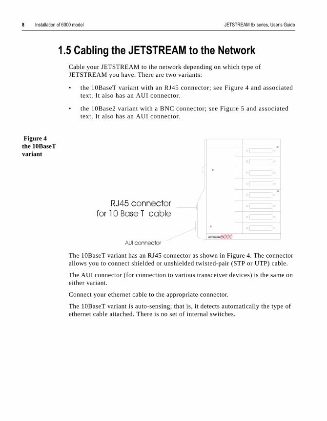
Figure 4the 10BaseT variant
The 10BaseT variant has an RJ45 connector as shown in Figure 4. The connallows you to connect shielded or unshielded twisted-pair (STP or UTP) cabl
The AUI connector (for connection to various transceiver devices) is the sameither variant.
Connect your ethernet cable to the appropriate connector.
The 10BaseT variant is auto-sensing; that is, it detects automatically the typethernet cable attached. There is no set of internal switches.
������������� �������� �������� 1����**�������%�&&&�����* 4
ctor tor me
t fit
witch
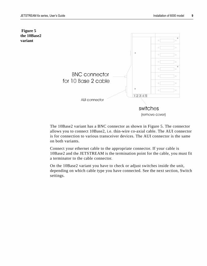
Figure 5the 10Base2 variant
The 10Base2 variant has a BNC connector as shown in Figure 5. The conneallows you to connect 10Base2, i.e. thin-wire co-axial cable. The AUI connecis for connection to various transceiver devices. The AUI connector is the saon both variants.
Connect your ethernet cable to the appropriate connector. If your cable is 10Base2 and the JETSTREAM is the termination point for the cable, you musa terminator to the cable connector.
On the 10Base2 variant you have to check or adjust switches inside the unit,depending on which cable type you have connected. See the next section, Ssettings.

$) 1����**�������%�&&&�����* ������������� �������� ��������
the
e)
ir
�$%%$ �3����������!,�
At the end of the unit next to the network connectors, remove the panel with Specialix logo on it. Inside the JETSTREAM you will see five switches.
Figure 6Default Switch settings (for a 10Base2 Connection)
These are the default settings. If you have implemented a 10Base2 (thin-wirconnection you can leave these switches as they are.
If you are using a 10Base5 (thick-wire connection), or an external twisted-patransceiver, you must move switches 1, 2 and 3 into the ‘down’ position as illustrated in Figure 7; (switches 4 and 5 are not used).
Figure 7Default Switch settings (for a Thin-wire Connection)

������������� �������� �������� 1����**�������%�&&&�����* $$
pply
ied.
rd
�$%1���3� �!,���������������5�
1. Take the pre-moulded cable with the 9-pin connector and attach the power suunit to the JETSTREAM’s power socket.
2. Tighten the retaining screws to secure the connection.
3. Plug the power supply unit into the mains supply using the mains cable suppl
4. Switch the power on at the mains.
CAUTION:Make sure that the power supply unit is kept in a dry, well ventilated place at all times. DO NOT block any of the vents and NEVER stack power supplyunits.
WARNING:This Specialix product is supplied with an external Power Supply Unit (PSU). Approvals gained by this product are dependent on the use of the product with the Specialix PSU. Use of a non-proprietary PSU, including PSUs supplied with other Specialix products, may also damage the unit and will invalidate your warranty.
Figure 8 LEDs and port numbers
At power up, after the internal diagnostics have been run, all four of the JETSTREAM’s LEDs should turn green. The LED next to the power supply socket (see Figure 8) indicates that the JETSTREAM has passed the on-boadiagnostic tests, i.e. it is working correctly.

$* 1����**�������%�&&&�����* ������������� �������� ��������
the ed.
5-es The
tput
to ou
this pt
TS#.
e
ing
The LED next to the ethernet connectors indicates network activity. If you transmit data across the network, it flashes green. If you receive data acrossnetwork, it flashes orange. If an error is detected on the network, it will flash rAfter initial start-up activity this LED will turn off.
The other 2 LEDs represent the JETSTREAM’s modules (ports 1-4 and ports8). These LEDs indicate that at least one of their ports are open. Since all linare set up as login connections by default, the LEDs turn green on power up.MTA LEDs function the same way.
�$%2������!,�5������ �!����
Now connect a terminal to port 8 on the JETSTREAM unit (the correct port isshown in Figure 8). Port 8 is the console port; all console messages will be outo it. See Section B.9 Terminals for cabling requirements.
You can use any type of terminal on the JETSTREAM. However, if you want use the menu system (Full Screen mode), as well as Command Line mode, ymust use, or emulate, one of the terminal types defined on the JETSTREAM(Wyse60, VT100 or Ansi). The default is Dumb.
Switch the terminal on. Set it to 9600 baud, 8 data bits, 1 stop bit, no parity; is the default configuration. Press <return> and the JETSTREAM login prom(MTS#) should be displayed.
Note. The cli prompt for the JETSTREAM is MTS followed by a character, e.g. MJETSTREAM has recently re-named from MTS (Modular Terminal Server).
Note. If you cannot emulate one of these terminal types, you must install using thCommand Line Interface (cli). Once you can communicate with a host you can download additional terminal definitions. This is described in Section 8.4 DownloadTerminal Definitions.
Now go to Chapter 3 (Initial Configuration).

������������� �������� �������� ���-�� �0��1����**�������%�)&&�����* $+
l.
The
� � � - � � � 0
(!���������!����/))������
*%$ (!� �������!
Note The descriptions of the 6500 model in this chapter apply equally to the 6501 mode
The JETSTREAM 6500 is a 19 inch rack-mounted version of the model 6000. front and rear views are shown below:
F�,� ��> F ��������*�2��+

$. ���-�� �0��1����**�������%�)&&�����* ������������� �������� ��������
rts.
the
ion.
�������3�G�21�4
This chapter contains the following sections:
• 2.2 Installation Checklist....... page 15
• 2.3 Installation....... page 15
• 2.4 No MTA....... page 16
• 2.5 Powering the JETSTREAM Up....... page 16
• 2.6 Setting Up the Console....... page 16
WARNING: the JETSTREAM 6500 and 6501 contain no user-serviceable pa
Any attempt to gain access to the inside of the chassis enclosure will nullify product warranty.
If your believe your product faulty it will have to be returned to the factory fordiagnosis and repair. Please confirm with your supplier before taking any act

������������� �������� �������� ���-�� �0��1����**�������%�)&&�����* $/
al
each and s are
e in on the just o-
*%* (!���������!� ���#����
• One JETSTREAM 6500.
• One mains lead for the JETSTREAM unit.
• JETSTREAM Supplemental diskette - containing MTSD, sample termindefinition files and a version of JETSTREAM software with SNMP support. (This diskette may also include a software upgrade).
• A terminal (or PC) to act as the console for the JETSTREAM.
• An IP address for your JETSTREAM (you allocate). Information on obtaining an IP (Internet) address for your Company/network is in Section G.10 Internet Registration.
*%+ (!���������!
*%+%$ (!������� ��#
To mount in a 19 inch rack, four holes are provided on the front panel, one at corner. The holes are of sufficient size to accommodate a variety of imperial metric type fasteners. Owing to the number of different 19inch racks, fastenernot provided. Please use fasteners suitable for your rack.
The weight and dimensions of the product are detailed in the Technical Specification, Section A.4 6500 and 6501 models.
Before connecting your JETSTREAM to the mains power, check that you havbeen supplied with a mains cable (power cord) suitable for the mains supplyyour country. The power range which the JETSTREAM will accept is printed the label next to the power input connector on the rear panel; it is repeated intechnical specification at the rear of this release note. There is no need to adthe JETSTREAM for different mains supply ratings, as the internal psu is autsensing.

$ ���-�� �0��1����**�������%�)&&�����* ������������� �������� ��������
s no
- nor
nt ode,
ity; n
*%+%* �������&��3� #
Cable your JETSTREAM to the network connection; you have a choice ofRJ45 and AUI connections.
*%+%+ ����3� ��(!���������!
For a brand new JETSTREAM 6500 unit, the software is pre-installed. There ifurther action required on your part.
*%. &�����
The JETSTREAM 6500 already has 16 user ports; there is no need to plug-in will the product accept - a Modular Terminal Adaptor (MTA).
*%/ ��3� �!,���������������5�
Connect the JETSTREAM to the mains power.
Turn on the power (I/O) switch on the rear of the unit.
*% �����!,�5������ �!����
Now connect a terminal to port 8 on the JETSTREAM unit (see Figure 9).Port 8 is the console port; all console messages will be output to it. See Section B.9 Terminals for cabling requirements.
You can use any type of terminal on the JETSTREAM. However, if you wato use the menu system (Full Screen mode), as well as Command Line myou must use, or emulate, one of the terminal types defined on the JETSTREAM (Wyse60, VT100 or Ansi). The default is Dumb.
Switch the terminal on. Set it to 9600 baud, 8 data bits, 1 stop bit, no parthis is the default configuration. Press <return> and the JETSTREAM logiprompt (MTS#) should be displayed.

������������� �������� �������� ���-�� �0��1����**�������%�)&&�����* $1
mand onal ns.
Note The cli prompt for the JETSTREAM is MTS followed by a character, e.g. MTS# . JETSTREAM has recently re-named from MTS (Modular Terminal Server).
Note If you cannot emulate one of these terminal types, you must install using the ComLine Interface (cli). Once you can communicate with a host you can download addititerminal definitions. This is described in Section 8.4 Downloading Terminal Definitio
�*%1������%%%%
Now go to Chapter 3 (Initial Configuration).

$2 ���-�� �0��1����**�������%�)&&�����* ������������� �������� ��������

������������� �������� �������� 1�����*����%�,� ����� $4
all
ction
st
� � � - � � � :
(!������ �!��,� ����!
+%$ (!� �������!
This chapter details the initial configuration of a JETSTREAM and applies tomodels. It contains the following sections:
• 3.2 Logging On....... page 19
• 3.3 JETSTREAM Configuration....... page 20
• 3.4 Setting Up the Host Table....... page 22
• 3.5 Reboot the JETSTREAM....... page 23
• 3.6 Verify Installation....... page 23
• 3.7 Software Upgrade....... page 23
+%* 6�,,�!,�7!
We assume you have connected and set up the console; if not go back to Se1.8 "Setting Up the Console" on page 12 either, for a model 6000 or 6001
Section 1.8 "Setting Up the Console" on page 12,
or, for a model 6500 or 6501,
Section 2.6 "Setting Up the Console" on page 16
At the login prompt, type admin and press <return>. At the password prompt, jupress <return>. This is the default admin user password. The Command Lineprompt (MTS#) will be displayed.
Note The cli prompt for the JETSTREAM is MTS followed by a character, e.g. MTS# . JETSTREAM has recently renamed from MTS (Modular Terminal Server).

*) 1�����*����%�,� ����� ������������� �������� ��������
xist
the
its
r 9
’.
You are now logged in as the system administrator. No other user accounts eon the system at this point.
To use Full Screen mode (menus), you must first set your terminal type. Useset line command as follows:
set l ine 8 termtype termtype
where termtype is wyse60, vt100 or ansi. If you want to emulate one of these terminal types, remember to change the terminal’s setup as well.
To enter Full Screen mode, type screen and press <return>. The main menu willbe displayed:
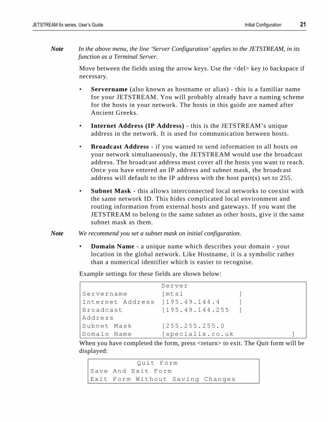
Note In the above menu, the line ‘Server Configuration’ applies to the JETSTREAM, in function as a Terminal Server.
A description of Full Screen mode, and how to use it, can be found in Chapte(Basic usage).
+%+ ���������� �!��,� ����!
NOTE: If you are unable to use Full Screen mode, you must enter the JETSTREAM configuration information through the Command Line using the commands set servername, set internet, set broadcast, set subnet and set domain. These are described in Chapter 11 (The CLI commands).
At the main menu, type ‘s’ and press <return> to select ‘Server ConfigurationThe following form will be displayed:
Main MenuSessionsCommand Line ModeUsersLine Conf igurat ionServer Conf igurat ionNetwork Conf igurat ion
ServerServername [ ]In ternet Address [ ]Broadcast Address
[ ]
Subnet Mask [ ]Domain Name [ ]
������������� �������� �������� 1�����*����%�,� ����� *$
its
ce if
e e
st each. t
h
ame
be
Note In the above menu, the line ‘Server Configuration’ applies to the JETSTREAM, in function as a Terminal Server.
Move between the fields using the arrow keys. Use the <del> key to backspanecessary.
• Servername (also known as hostname or alias) - this is a familiar namfor your JETSTREAM. You will probably already have a naming schemfor the hosts in your network. The hosts in this guide are named afterAncient Greeks.
• Internet Address (IP Address) - this is the JETSTREAM’s unique address in the network. It is used for communication between hosts.
• Broadcast Address - if you wanted to send information to all hosts on your network simultaneously, the JETSTREAM would use the broadcaaddress. The broadcast address must cover all the hosts you want to rOnce you have entered an IP address and subnet mask, the broadcasaddress will default to the IP address with the host part(s) set to 255.
• Subnet Mask - this allows interconnected local networks to coexist witthe same network ID. This hides complicated local environment and routing information from external hosts and gateways. If you want theJETSTREAM to belong to the same subnet as other hosts, give it the ssubnet mask as them.
Note We recommend you set a subnet mask on initial configuration.
• Domain Name - a unique name which describes your domain - your location in the global network. Like Hostname, it is a symbolic rather than a numerical identifier which is easier to recognise.
Example settings for these fields are shown below:
When you have completed the form, press <return> to exit. The Quit form willdisplayed:
ServerServername [mtsl ]Internet Address [195.49.144.4 ]Broadcast Address
[195.49.144.255 ]
Subnet Mask [255.255.255.0Domain Name [special ix .co.uk ]
Qui t FormSave And Exi t FormExi t Form Without Saving Changes

** 1�����*����%�,� ����� ������������� �������� ��������
ed
he able.
se
s is
The first option will be highlighted; press <return> to save. You will be returnto the main menu.
��� +�� �������������"��-��� ��� ���%���� ����������������%�,� �����.������--�����E�
'���%�,� ������ ��� �(
+%. �����!,�5������8���������
The JETSTREAM needs to know the host names and internet addresses of tother hosts in the network (or any hosts anywhere on the internet) which youwant to communicate with on a regular basis. These are added to the Host TYou can add up to twenty hosts. Select ‘Host Table’ from the Network Configuration menu; the Host Table menu will be displayed:
Select ‘Add Host’ from the menu. You will be asked to enter the host name:
Type in the name of the host (14 characters maximum) and press <return>. Uthe <del> key to backspace if necessary.
Select ‘Change Host’ from the Host Table menu. The following form will be displayed:
This form will list all hosts added to the host table. The default internet addres0.0.0.1. Enter the correct internet address of each host. Use the <del> key tobackspace if necessary.
Host TableAdd HostChange HostDelete Host
Enter Host Name:
HostsHostname Internet Addresssocrates [192.49.144.4 ]ar is tot le [0.0.0.1 ]p lato [0.0.0.1 ]sophocles [0.0.0.1 ]homer [0.0.0.1 ]pythagoras [0.0.0.1 ]

������������� �������� �������� 1�����*����%�,� ����� *+
ot
be
rror,
and nit ette of
+%/ ��������������������
Whenever you set or change the JETSTREAM Configuration, you must rebothe JETSTREAM. This will broadcast the information across the network.
NOTE: If you are not using Full Screen mode, use the command reboot server from the command line.
Select ‘Reboot’ from the Network Configuration menu. The Reboot menu will displayed:
Select ‘Reboot Server’. You will be asked to confirm the reboot:
Type ‘y’ to reboot. When the JETSTREAM has been rebooted the MTS loginprompt will be displayed.
Note In the above menus, the ‘Server’ applies to the JETSTREAM, in its function as a Terminal Server.
+% 9� ����(!���������!
To check that you have installed the JETSTREAM successfully, try to ping a remote host using the following command:
ping hostname
Choose a host that you have defined in the host table. If no packet loss is reported, your JETSTREAM unit is ready to use. If the command returns an erefer to Section 11.22 ping.
+%1 ����3� ��5�, ���
You may have been supplied with a software upgrade. Use the version comm(Section 11.57 version) to check the version of JETSTREAM software your uis running. Compare this with the version number on the Supplementary disksupplied with the JETSTREAM. If the diskette contains a more recent versionsoftware, you should install it.
RebootReboot ServerSet Net Reboot ing
Conf i rm Reboot Server (y/n)

*. 1�����*����%�,� ����� ������������� �������� ��������
er 8
Copy the software upgrade onto another TCP/IP host and download to the JETSTREAM via net rebooting. The procedure for this is described in Chapt(System Administration).
������������� �������� �������� ������,��-�G�,�������������� */
the ions re
e ls. t a
as
nd irect in
rrect. nd
� � � - � � � 7
�����!,�5��6�,�!� �!!�����!�
�.%$�(!� �������!
By default, JETSTREAM lines are configured as normal connections. This is a login connection to the JETSTREAM unit - you have been using one to installJETSTREAM. Once logged in, the user can start up to four telnet/rlogin sessto remote hosts. The admin user can predefine these sessions, even configuthem to start automatically on login to the JETSTREAM. Although users havaccess to JETSTREAM commands, this can be restricted by use of user leveFor these users you must create a login account on the JETSTREAM and sepassword.
If multiple sessions are not a requirement, you may want to reconfigure linesdirect or silent login connections. These allow the user to log straight into a specific host, completely bypassing the JETSTREAM login. This is quicker aeasier for users and they won’t need to learn how to use the JETSTREAM. Dand silent connections are described in more detail in “Direct and Silent LogConnections”.
You must also make sure that the hardware characteristics of the lines are coThe default line configuration is 9600 baud, 8 data bits, 1 stop bit, no parity asoftware flow control. Normal connections also require the terminal type andnumber of video pages to be set. “Line Settings” describes how to edit JETSTREAM line settings.
NOTE: The JETSTREAM will support a maximum of 64 sessions. If you have an 8- or 16-port configuration, this enables you to run up to 4 sessions on all ports if required. Memory limitations may also restrict the number of sessions you can run. You can check the amount of available memory using the CLI heap command.

* ������,��-�G�,�������������� ������������� �������� ��������
this
into are e
,
en not
If
an
�.%*� ����� ���!��!��
This chapter is divided into the following sections:
• 4.3 Direct and Silent Login Connections...... page 26
• 4.4 Setting Up Direct/Silent Login Connections...... page 27
• 4.5 Line Settings...... page 28
• 4.6 Set All Values To Current Field Value (Global Replace)...... page 29
• 4.7 Reset to Default...... page 30
Note. An overview of all line types (including those discussed in other chapters inmanual) is provided in Section A.5 Summary of Line types.
�.%+�'� �����!������!��6�,�!� �!!�����!�
Direct connections bypass the JETSTREAM enabling the user to log straight a specific host. A direct connection is recommended where multiple sessionsnot a requirement. The message ‘Press return to continue’ is displayed on thuser’s screen. The user must hit a key to display the host login prompt. The message is redisplayed on logout.
NOTE: On the console port (no. 8), if the user presses <esc> instead of <return>an JETSTREAM login prompt can be obtained.
Silent connections are the same as direct connections except that they are permanently established. The host login prompt is displayed on the screen. Logging out redisplays this prompt. Silent connections, unlike direct connections, however, make permanent use of pseudo tty resources and constantly respawn getty processes. They consume host resources even whin use.
You can select the telnet or rlogin protocol for direct and silent connections. unsure which to use, consider the following:
• Telnet can be used to access both UNIX and non-UNIX hosts; rlogin cnormally only be used with UNIX hosts.

������������� �������� �������� ������,��-�G�,�������������� *1
e ure
s
lled.
ct be
• Telnet provides more options for connecting to hosts, but rlogin uses fewer system resources.
• Rlogin passes your user name and a terminal type to the host. On somolder versions of SCO UNIX, however, these may not be passed. Failto pass the terminal type results in your TERM variable being set to ‘unknown’ upon login.
�.%.������!,�5��'� ���:����!��6�,�!� �!!�����!�
������!�;����3���!�Select ‘Virtual Circuits’ from the Line Configuration menu. The Virtual Circuitform will be displayed:
By default, the line type is set to normal , the TCP Port to 23 (telnet) and the hostname to the first host entered in the host table.
Sixteen lines are created, irrespective of the number of ports physically instaScroll up and down the list using the arrow keys or the <PgUp> and <PgDn>keys.
• In the Hostname field use the spacebar to cycle through the available hosts. Select the host that you want the user to log into.
• In the Type field use the spacebar to cycle through the line types. Seleone from dir tel, sil tel, dir rlg and sil rlg. Port 8 (the Console port) can configured as any of line types, except for silent and printer (see next paragraph).
To configure the console port as silent or printer line type, you must
Vir tual Circui tsLine hostname Type Host Port MTS Port1 [socrates ] [normal ] [23 ] [ ]2 [socrates ] [normal ] [23 ] [ ]3 [socrates ] [normal ] [23 ] [ ]4 [socrates ] [normal ] [23 ] [ ]5 [socrates ] [normal ] [23 ] [ ]6 [socrates ] [normal ] [23 ] [ ]7 [socrates ] [normal ] [23 ] [ ]8 [socrates ] Console [23 ] [ ]9 [socrates ] [normal ] [23 ] [ ]10 [socrates ] [normal ] [23 ] [ ]11 [socrates ] [normal ] [23 ] [ ]12 [socrates ] [normal ] [23 ] [ ]13 [socrates ] [normal ] [23 ] [ ]14 [socrates ] [normal ] [23 ] [ ]15 [socrates ] [normal ] [23 ] [ ]

*2 ������,��-�G�,�������������� ������������� �������� ��������
s
nd
her
rm
e
telnet into the JETSTREAM. This is a precaution to ensure you alwayhave access to configure the JETSTREAM, irrespective of line type setting on port 8.
The other fields can be ignored.
HINT. If you want to configure several lines with the same parameters, you may want to use the Global Replace or Reset to Default features (see Set All Values To Current Field Value (Global Replace) and Reset to Default).
�.%/�6�!�������!,�
������!�;����3���!�The default line configuration is 9600 baud, 8 data bits, 1 stop bit, no parity asoftware flow control.
Changes to a login line will take effect the next time the user logs in. The exception to this is the line that you are logged into. On this line, changes to theterminal type and the number of video pages will take effect immediately. Otchanges will take effect the next time you log in.
Select ‘Line Settings’ from the Line Configuration menu. The Line Settings fowill be displayed:
Scroll through the list using the arrow keys or <PgUp> and <PgDn> keys. Usthe spacebar to cycle through the options in each field.
The ‘Terminal’, ‘Pages’ and ‘User’ fields are defined as follows:
Line Set t ingsLine Speed Terminal Modem Flow Bits Pari ty Stop Pages User1 [9600 ] [dumb ] [of f ] [sof t ] [8] [none] [1] [4] [ ]2 [9600 ] [dumb ] [of f ] [sof t ] [8] [none] [1] [4] [ ]3 [9600 ] [dumb ] [of f ] [sof t ] [8] [none] [1] [4] [ ]4 [9600 ] [dumb ] [of f ] [sof t ] [8] [none] [1] [4] [ ]5 [9600 ] [dumb ] [of f ] [sof t ] [8] [none] [1] [4] [ ]6 [9600 ] [dumb ] [of f ] [sof t ] [8] [none] [1] [4] [ ]7 [9600 ] [dumb ] [of f ] [sof t ] [8] [none] [1] [4] [ ]8 [9600 ] [dumb ] [of f ] [sof t ] [8] [none] [1] [4] [ ]9 [9600 ] [dumb ] [of f ] [sof t ] [8] [none] [1] [4] [ ]10 [9600 ] [dumb ] [of f ] [sof t ] [8] [none] [1] [4] [ ]11 [9600 ] [dumb ] [of f ] [sof t ] [8] [none] [1] [4] [ ]12 [9600 ] [dumb ] [of f ] [sof t ] [8] [none] [1] [4] [ ]13 [9600 ] [dumb ] [of f ] [sof t ] [8] [none] [1] [4] [ ]14 [9600 ] [dumb ] [of f ] [sof t ] [8] [none] [1] [4] [ ]15 [9600 ] [dumb ] [of f ] [sof t ] [8] [none] [1] [4] [ ]

������������� �������� �������� ������,��-�G�,�������������� *4
ct
ed
to eir
ory login
s
t the
om
de
• Terminal - (normal connections) The default terminal type is dumb. If you want to use Full Screen mode (menus) on the line, you must seleone of the predefined terminal types (Wyse60, Ansi or VT100). If you can’t use or emulate one of these types, you can download up to threeadditional terminal definitions of your own choice using the Extratermsutility (see Section 8.4 Downloading Terminal Definitions). This will explain the term1, term2 and term3 options available in this field.
• Pages - (normal connections) This is the number of video pages supported by the terminal attached to the line. If you don’t specify thecorrect number of pages, you may experience problems with page displays when switching between sessions. The documentation suppliwith your terminal should tell you how many pages it supports.
• User - This field enables you to define the name of the line user. On normal connections, this is an option, enabling you to dedicate the linea specific user. This user won’t be prompted for their user name, just thpassword. On direct and silent rlogin connections, this field is mandatbecause the user name is always passed to the UNIX host under the rprotocol.
HINT: If you want to configure several lines with the same parameters, you may want to use the Global Replace or Reset to Default features (see Section“Set All Values To Current Field Value (Global Replace)” and “Reset to Default”).
�.%���������9��������� � �!��������9����
<��������������=
This feature enables you to change a parameter (e.g. line type) on all lines asame time. It can be used in the Virtual Circuits and Line Settings forms.
• Select a line and make the required change (e.g. change line speed fr9600 baud to 38400 baud).
• Keeping the cursor in the modified field, press <return> to display theQuit menu:
• Select ‘Set All Values To Current Field Value’. The change will be mato all lines.
Quit FormSave And Exi t FormExi t Form Without Saving ChangesSet Al l Values To Current F ie ld ValueReset To Defaul t

+) ������,��-�G�,�������������� ������������� �������� ��������
s. It its
me l be
�.%1����������'�������
�������!� This feature enables you to reset all JETSTREAM lines to the default settingcan be used in the Virtual Circuits and Line Settings forms. In the Virtual Circuform, the line type will be set to ‘normal’, the TCP Port to ‘23’ and the hostnato the first host entered in the host table. In the line settings form, all lines wilset to 9600 baud, 8 data bits, 1 stop bit, no parity and software flow control.
• Press <return> to display the Quit menu:
• Select ‘Reset To Default’. You will be asked to confirm the reset:ws
• Type ‘y’ to reset all the lines.
Quit FormSave And Exi t FormExi t Form Without Saving ChangesSet Al l Values To Current F ie ld ValueReset To Defaul t
Reset Al l L ines (y/n)

������������� �������� �������� �������� �������%���� � +$
nt. vel s. A
� � � - � � � )
����!��� ����!����5�� �
/%$ (!� �������!
Before a user can log into the JETSTREAM, he/she must have a login accouJETSTREAM login accounts are password-protected and assigned a user lewhich determines the level of access the user has to JETSTREAM commandmaximum of 48 user accounts can be created.
NOTE: Only users that log into the JETSTREAM (normal connections), or have the option to direct telnet/rlogin, require JETSTREAM login accounts.
/%* ����� � �!��!��
This chapter is divided into the following sections:
• 5.3 User Levels...... page 32
• 5.4 Add a User Account...... page 32
• 5.5 Configure a User Account...... page 32
• 5.6 Predefine User Sessions...... page 33
• 5.7 Change a User’s Password...... page 34
• 5.8 Delete a User Account...... page 34
• 5.9 Becoming Admin User...... page 35
+* �������� �������%���� � ������������� �������� ��������
ss the
the
ly. r
they ined
the
.
n g
sers
/%+ 5�� �6�>���
There are three user levels which can be used to determine the level of acceuser has to JETSTREAM commands:
• Admin - The system administrator. The admin user has total access toserver. You can create more than one admin user account but it is recommended that you only have one.
• Normal (default) - Normal users have access to the Sessions menu onThey can start sessions, predefine sessions and change their own useenvironment.
• Restricted - These users have access to a restricted Sessions menu; can only open sessions predefined for them by the admin user. Predefsessions can even be configured to start automatically at login.
/%. ������5�� ������!�
������� Select ‘Add User’ from the Users menu.
Enter a username, not exceeding eight characters, and press <return>. Use <del> key to backspace if necessary.
Enter a password, again not exceeding eight characters, and press <return>
Re-enter the password and press <return>.
Admin users can change user passwords using the ‘Set Password’ feature described in “Change a User’s Password”. Normal users can change their owpasswords using the ‘Set Up User’ feature described in Section 9.4 Changinyour Password.
/%/ �!��,� ����5�� ������!�
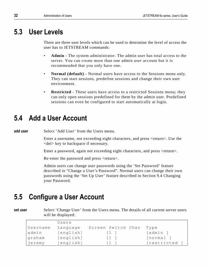
������� Select ‘Change User’ from the Users menu. The details of all current server uwill be displayed:
UsersUsername Language Screen Switch Char Typeadmin [engl ish] [1 ] [admin ]graham [engl ish] [1 ] [normal ]jeremy [engl ish] [1 ] [ restr icted ]
������������� �������� �������� �������� �������%���� � ++
veral
run ‘1’ d
e pe
n ser
ust open
yed
When you have a large number of users on the system, this form may take seseconds to display.
• Language - currently this can only be set to ‘english’.
• Screen switch character - this is the ‘hot-key’ command used, in conjunction with other keys, for switching between sessions. This mayneed to be changed if it clashes with an application a user is going toin one of their sessions. It must be entered in hex format; the default is(^A). Refer to the ascii code chart in Section F.2 ASCII to Decimal anHex Code Chart. Normal users can change their own screen switch character using the ‘Set Up User’ option on the Sessions menu.
• Type - this field cycles through ‘admin’, ‘normal’ and ‘restricted’. Thesare described in “User Levels” section. You cannot change the user tyof the default admin user account.
If you set up any restricted users, you must predefine their sessions; they caonly open sessions predefined for them by the admin user (see “Predefine USessions” section).
/% � �����!��5�� �������!�
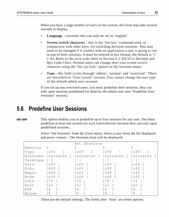
������� This option enables you to predefine up to four sessions for any user. You mpredefine at least one session for each restricted user because they can onlypredefined sessions.
Select ‘Set Sessions’ from the Users menu. Select a user from the list displaand press <return>. The Sessions form will be displayed:
These are the default settings. The fields after ‘Auto’ are telnet options.
Set SessionsSession 1 2 3 4Type [of f ] [o f f ] [o f f ] [o f f ]Hostname [socrates ] [socrates ] [socrates ] [socrates ]Termtype [ ] [ ] [ ] [ ]Auto [of f ] [o f f ] [o f f ] [o f f ]Echo [of f ] [o f f ] [o f f ] [o f f ]Mapnl [of f ] [o f f ] [o f f ] [o f f ]Mode [off ] [o f f ] [o f f ] [o f f ]In tr [7f ] [7 f ] [7 f ] [7 f ]Quit [1c ] [1c ] [1c ] [1c ]EOF [4 ] [4 ] [4 ] [4 ]Erase [8 ] [8 ] [8 ] [8 ]

+. �������� �������%���� � ������������� �������� ��������
not.
ost
y rt,
press
or
• Type - ‘off’, ‘telnet’ or ‘rlogin’. When not set to ‘off’, a predefined session will use up one of the user’s 4 session slots whether active or
• Hostname - you can only predefine sessions on hosts defined in the htable. The first entry in the host table will be entered as the default.
• Termtype - when connecting to a UNIX host, you must define your terminal type in accordance with its UNIX TERM variable.
• Auto - If this field is set to ‘on’, the session will start up auto- maticallwhen the user logs on. When more than one session is set to auto-stasession 1 will be displayed first. If this field is set to ‘off’, the session must be started using the ‘Start Predefined Sessions’ option on the Sessions menu.
/%1 ��!,����5�� ?������3� �
������� Select ‘Set Password’ from the Users menu.
Select a user from the list displayed.
You will be prompted to enter a password. This can be up to eight characterslong. Use the <del> key to backspace if necessary. Enter the password and <return>.
When prompted, re-enter the password and press <return>.
The password change will take effect next time the user logs in.
/%2 '��������5�� ������!�
���������� You will be unable to delete the default admin user, users that are logged in users dedicated to a specific line.
Select ‘Delete User’ from the Users menu.
Select the user that you want to delete from the list displayed.
You will be asked to confirm the deletion; type ‘y’ and press <return>. The user will be deleted.

������������� �������� �������� �������� �������%���� � +/
in t e
ess
/%4 @�����!,�����!�5��
!� ����
����!�������!
This menu option enables you to become an admin user, if you know the admpassword. Prior tothis action you must be a ‘normal user’ (the default); selec‘Become Admin User’ from the Sessions menu. You will be asked to enter thadmin user password
You will then be logged in as the admin user. The full main menu will be displayed. It should be noted that you can’t return to being a normal user unlyou log out and log back in again.
Enter Passwords:

+ �������� �������%���� � ������������� �������� ��������
������������� �������� �������� 3��+� "����%�,� ����� +1
bes your
� � � - � � �
&��3� #� �!��,� ����!
%$ (!� �������!
Through the options of the Network Configuration menu, you can tell the JETSTREAM how the rest of your network is configured. This chapter descrihow to define the other TCP/IP hosts, the nameservers and the gateways in network.
This chapter contains the following sections:
• 6.2 Host Table...... page 38
• 6.3 Add Host...... page 38
• 6.4 Change Host...... page 38
• 6.5 Delete Host...... page 39
• 6.6 Name Servers...... page 39
• 6.7 Add Name Server...... page 40
• 6.8 Change Name Server...... page 40
• 6.9 Delete Name Server...... page 41
• 6.10 Gateways...... page 41
• 6.11 Add Gateway...... page 42
• 6.12 Change Gateway...... page 43
• 6.13 Delete Gateway...... page 43
+2 3��+� "����%�,� ����� ������������� �������� ��������
all the ost tions
nu
se be
%* 8���������
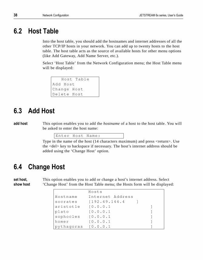
Into the host table, you should add the hostnames and internet addresses of other TCP/IP hosts in your network. You can add up to twenty hosts to the htable. The host table acts as the source of available hosts for other menu op(like Add Gateway, Add Name Server, etc.).
Select ‘Host Table’ from the Network Configuration menu; the Host Table mewill be displayed:
%+ ����8���
�������� This option enables you to add the hostname of a host to the host table. You will be asked to enter the host name:
Type in the name of the host (14 characters maximum) and press <return>. Uthe <del> key to backspace if necessary. The host’s internet address should added using the ‘Change Host’ option.
%. ��!,��8���
��������;�
���3�����
This option enables you to add or change a host’s internet address. Select ‘Change Host’ from the Host Table menu; the Hosts form will be displayed:
Host TableAdd HostChange HostDelete Host
Enter Host Name:
HostsHostname Internet Addresssocrates [192.49.144.4 ]ar is tot le [0.0.0.1 ]p lato [0.0.0.1 ]sophocles [0.0.0.1 ]homer [0.0.0.1 ]pythagoras [0.0.0.1 ]

������������� �������� �������� 3��+� "����%�,� ����� +4
s is
or he
to
rnet a ot
This form will list all hosts added to the host table. The default internet addres0.0.0.1. Enter the correct internet address of each host. Use the <del> key tobackspace if necessary.
%/ '������8���
����������� This option enables you to delete an entry from the host table. If a host is referenced by a predefined session, or is defined as a gateway, name serverboot host, you won’t be allowed to delete it. When you select ‘Delete Host’, thost table will be displayed:
Select the host that you want to delete and press <return>. You will be askedconfirm the deletion:
Type ‘y’ to delete the host, ‘n’ to cancel the command.
% &������ >� �
A name server functions as a database of hostnames and corresponding inteaddresses. It will contain the details of all the hosts in your local network andpossibly other regularly used hosts beyond. If the JETSTREAM can’t resolvehostname it will consult the name server. This enables you to access hosts ndefined in the JETSTREAM host table.
NOTE: You can only do this from the command line or by using silent telnet/rlogin connections. Using Full Screen mode you are forced to select a host from the host table.
Hostssocratesar istot leplatosophocleshomerpythagoras
Conf i rm Delete Host ‘socrates’ (y /n)
.) 3��+� "����%�,� ����� ������������� �������� ��������
ers
will
must
t.
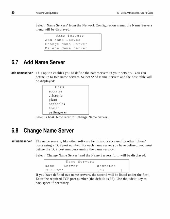
Select ‘Name Servers’ from the Network Configuration menu; the Name Servmenu will be displayed:
%1 ����&������ >�
����!����� >� This option enables you to define the nameservers in your network. You candefine up to two name servers. Select ‘Add Name Server’ and the host tablebe displayed:
Select a host. Now refer to ‘Change Name Server’.
%2 ��!,��&������ >�
����!����� >� The name service, like other software facilities, is accessed by other ‘client’ hosts using a TCP port number. For each name server you have defined, youdefine the TCP port number running the name service.
Select ‘Change Name Server’ and the Name Servers form will be displayed:
If you have defined two name servers, the second will be listed under the firsEnter the required TCP port number (the default is 53). Use the <del> key tobackspace if necessary.
Name ServersAdd Name ServerChange Name ServerDelete Name Server
Hostssocratesar istot leplatosophocleshomerpythagoras
Name ServersName Server socratesTCP Port [53 ]

������������� �������� �������� 3��+� "����%�,� ����� .$
m a me me
the
u via l ere
r
o
tive.
%4 '������&������ >�
�������!����� >� If your name service is moved to a different host, or removed permanently frohost, you can use this option to remove the unwanted host from the list of naservers. The host will NOT be deleted from the host table. Select ‘Delete NaServer’ to list your name servers:
Select the name server that you want to delete. You will be asked to confirmdeletion:
Type ‘y’ to delete the nameserver, ‘n’ to cancel the command.
%$) ����3���
Gateways are hosts that connect Local Area Networks (LANs) together. If yowant to access a host which isn’t on your local network you will be connecteda gateway. Gateways route data via other gateways until the destination locanetwork is reached. The JETSTREAM will recognise up to eight gateways. Thare three types:
• Default - this is a gateway which provides general access beyond youlocal network.
• Host - this a gateway reserved for accessing a specific host external tyour local network.
• Network - this is a gateway reserved for accessing a specific networkexternal to your local network.
Particularly useful when checking routes to/from gateways is the show route command; see Section 11.51 show route.
%$)%$ ����>���!�������������3���
The JETSTREAM supports both active and static gateways. The default is acDefinitions of these types are as follows:
Delete Name Serverssocratesplato
Conf i rm Delete Name Server ‘socrates’ (y/n)

.* 3��+� "����%�,� ����� ������������� �������� ��������
ing s ) it
ting
ill
.
nly be
ion
Active gateway: a gateway which is temporarily listed in the JETSTREAM’s routtable (while RIP packets are received). If the JETSTREAM detectthat the gateway is no longer operating (no RIP packets receivedwill be deleted from the routing table.
Static gateway: a gateway which is permanently listed in the JETSTREAM’s routable. It is thus always available.
%$)%* 8�3���� �!��,� ��������3��
Select ‘Gateway’ from the Network Configuration menu; the Gateway menu wbe displayed:
You can also type ‘add gateway’ at the command line prompt.
Note You can configure a single static gateway using BOOTP. See Section 8.5 BOOTP
%$$ ��������3��
����,���3�� This option enables you to define the gateways in your network. Hosts can obe defined as a gateway once. Select ‘Add Gateway’ and the host table will displayed:
Select a host. Now define the gateway type using the ‘Change Gateway’ opt(see below).
GatewayAdd GatewayChange GatewayDelete Gateway
Hostssocratesar istot leplatosophocleshomerpythagoras

������������� �������� �������� 3��+� "����%�,� ����� .+
ne
t
ay,
to m
%$* ��!,������3��
����,���3��
���3�,���3���
When you have added a gateway, you must define its type. Select ‘Change Gateway’ and the Gateways form will be displayed (for example):
This form lists all gateways defined for your network. In this example, only ohas been defined.
In the Type field, use the spacebar to cycle through ‘host’, ‘network’ and ‘default’. If you set the field to ‘host’ or ‘network’, you must include the interneaddress of the target host or network. If you change a gateway from ‘host’ or‘network’ to ‘default’, the internet address will be ignored.
In the ‘Static’ field, use the spacebar to toggle between ‘yes’ for a static gatewand ‘no’ for an active gateway.
Use the <del> key to backspace if necessary.
%$+ '����������3��
�������,���3�� If a host on your network is retired from gateway duty, you can use this optiondelete it from the list of gateways. Note that the host will NOT be deleted frothe host table. Select ‘Delete Gateway’ to list your gateways:
Select the gateway that you want to delete. You will be asked to confirm the deletion:
Type ‘y’ to delete the gateway, ‘n’ to cancel the command.
GatewaysHostname Type Internet Address Stat icsocrates [host] [ ] [no]
Delete Gatewaysocratesplato
Conf i rm Delete Gateway ‘p lato ’ (y /n)

.. 3��+� "����%�,� ����� ������������� �������� ��������

������������� �������� �������� �� ���������%�,� ����� ./
into
� � � - � � � ?
��>�!���� �!��,� ����!
1%$ (!� �������!
This chapter describes more advanced uses of the JETSTREAM. It is dividedthe following sections:
• 7.2 Overview of Line Types...... page 46
• 7.3 Remote Printing Using RCP...... page 47
• 7.4 Remote Printing Using Host-Based Print Handling Software...... page 49
• 7.5 Dialin Modem Connections...... page 50
• 7.6 Dialout Modem Connections...... page 51
• 7.7 bidirectional Modem Connections...... page 52
• 7.8 Modem and Printer Handling Using MTSD...... page 53)
• 7.9 Reverse Telnet Connection...... page 60
• 7.10 Set Security...... page 62
• 7.11 Simple Network Management Protocol...... page 63
. �� ���������%�,� ����� ������������� �������� ��������
d in
r
IP
uter
ed he
h
uld l
t alin
nual)
1%* 7>� >��3����6�!�������
Setting up login connections on JETSTREAM ports has already been describeSection 4.4 Setting Up Direct/Silent Login Connections. The JETSTREAM, however, provides much greater scope for connections into and out from younetwork. This section gives an overview of the line types provided and their practical uses.
• Printer - this line type enables remote file copy, using RCP, from TCP/hosts to printers connected to the JETSTREAM.
• Silent/Direct Raw - these line types enable external machines to establish connections on TCP/IP hosts via JETSTREAM ports. The JETSTREAM is effectively transparent. Silent connections are established automatically and are more suitable for computer to compcommunication. A typical use is for dialin connections. Direct connections are established by pressing <return> and are recommendfor user applications. This prevents TCP resources being used while tconnection is not in use. On the console port (port 8) pressing <esc> instead of <return> enables the user to obtain a JETSTREAM login.
• Reverse Raw - this line type enables TCP/IP hosts to establish connections on external machines via JETSTREAM ports. The JETSTREAM is effectively transparent. Reverse raw connections are typically used to access printers or dialout modems in conjunction withost-based print/modem handling software.
• Reverse Telnet - this line type enables TCP/IP hosts to establish loginconnections on external machines via JETSTREAM ports. The JETSTREAM is effectively transparent. Reverse telnet connections cobe used for access to machines like protocol converters and statisticamultiplexors or for access to Wide Area Networks (WANs).
• Bidir - this line type allows a bidirectional modem connection to be seup on an JETSTREAM port. This enables the modem to be used for diand dialout purposes simultaneously.
Note An overview of all line types (including those discussed in other chapters in this mais provided in Section A.5 Summary of Line types.

������������� �������� �������� �� ���������%�,� ����� .1
osts he
to
ed
into re the
er line.
hell se
t to
r
1%+ �������� �!��!,�5��!,�� �
������!� Printers connected to JETSTREAM ports can be accessed by other TCP/IP hin the network using the RCP protocol. These connections are set up using tprinter line type.
Select ‘Virtual Circuits’ from the Line Configuration menu. Set the Type field ‘printer’. Look at the example line below:
The Hostname, Host Port and MTS Port fields may contain default or last-usvalues, but these will be ignored by JETSTREAM.
Note To configure the console port (port 8) as silent or printer line type, you must telnet the JETSTREAM. This is a precaution to ensure you can always access to configuJETSTREAM, irrespective of line type setting on port 8.
There are two ways to direct output to the printer: you can either modify the printer interface script(s) to direct output across the network using RCP raththan to a local printer, or you can issue the rcp command from the command
On typical UNIX V.3.2 systems, the print spooler provides a set of back-end sscripts for talking to printers. An example of how you might modify one of thescripts for remote printing is given below.
These scripts are usually found in the /usr/spool/lp directory tree. If you wanuse all printer ports as a hunt group, specify servername: instead of servername:mts_pn. The JETSTREAM will output the job to the first free printeport it comes across.
Line Hostname Type Host Port MTS Port[1] [ ] [pr inter ] [ ] [ ]

.2 �� ���������%�,� ����� ������������� �������� ��������
e eed
To execute an rcp job from the command line, use the following command:
rcp filename servername :mts_p n
Where:
servername is the hostname assigned to the JETSTREAM unit.
n is the port that the printer is connected to.
If the port is busy, or not set up as a printer port, the job will fail.
Multiple ‘printer’ connections will act as a hunt group, providing the same typof printer is connected to each. To direct output to the hunt group, you don’t nto specify a port number:
rcp f i lename servername :
JETSTREAM will output the file to the first free printer port it finds.
whi le [ “$copies” -gt 0 ]do
for f i ledo
whi le t ruedorcp $f i le servername:mts_pni f [ $? = 0 ]thenbreakf idone
donecopies=’expr $copies -1 ’
done

������������� �������� �������� �� ���������%�,� ����� .4
using
t an be
at
g he
. The um
to the o do
1%. �������� �!��!,�5��!,�8���0@�����
� �!��8�!���!,�����3� �
������!� Printers connected to JETSTREAM ports can be accessed by TCP/IP hosts print handling software. This type of connection uses the reverse raw line type. The print handling software needs to know the name of the JETSTREAM uniand the TCP Port number assigned to the printer port. The same TCP Port cassigned to a number of ports to form a hunt group.
To setup a reverse raw printing connection, follow these steps:
1. Select ‘Virtual Circuits’ from the Line Configuration menu and select the line thyou want to configure.
2. Set the Type field to ‘rev raw’.
3. Enter a TCP port number in the MTS Port field. If you select a TCP port beinused by another process, a connection will not be made (using a number in trange 900-1023 should work).
4. To set up a hunt group, assign the same TCP port number to each printer lineJETSTREAM will use the first free line in the group. You can set up a maximof eight hunt groups.
The line should now be configured similar to the following:
The Hostname and Host Port fields may contain default or last-used values, but these will be ignored. Save the changes.
5. On each TCP/IP host wanting to access the printer, set up a process to talk TCP port assigned to the JETSTREAM port. You can either write a program tthis, or you can use the MTSD print handling service described in the sectionSection 7.8 Modem and Printer Handling Using MTSD.
Line Hostname Type Host Port MTS Port[1] [ ] [ rev raw ] [ ] [1000 ]
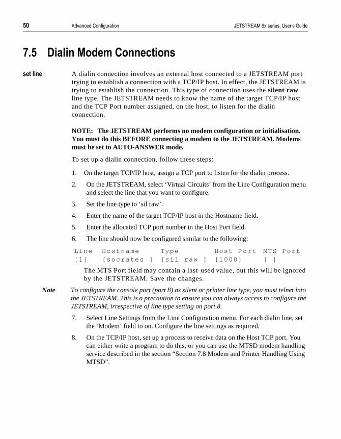
/) �� ���������%�,� ����� ������������� �������� ��������
rt is
st
u
ed
into re the
set
You ling ing
1%/ '����!������� �!!�����!�
������!� A dialin connection involves an external host connected to a JETSTREAM potrying to establish a connection with a TCP/IP host. In effect, the JETSTREAMtrying to establish the connection. This type of connection uses the silent raw line type. The JETSTREAM needs to know the name of the target TCP/IP hoand the TCP Port number assigned, on the host, to listen for the dialin connection.
NOTE: The JETSTREAM performs no modem configuration or initialisation. You must do this BEFORE connecting a modem to the JETSTREAM. Modems must be set to AUTO-ANSWER mode.
To set up a dialin connection, follow these steps:
1. On the target TCP/IP host, assign a TCP port to listen for the dialin process.
2. On the JETSTREAM, select ‘Virtual Circuits’ from the Line Configuration menand select the line that you want to configure.
3. Set the line type to ‘sil raw’.
4. Enter the name of the target TCP/IP host in the Hostname field.
5. Enter the allocated TCP port number in the Host Port field.
6. The line should now be configured similar to the following:
The MTS Port field may contain a last-used value, but this will be ignorby the JETSTREAM. Save the changes.
Note To configure the console port (port 8) as silent or printer line type, you must telnet the JETSTREAM. This is a precaution to ensure you can always access to configuJETSTREAM, irrespective of line type setting on port 8.
7. Select Line Settings from the Line Configuration menu. For each dialin line, the ‘Modem’ field to on. Configure the line settings as required.
8. On the TCP/IP host, set up a process to receive data on the Host TCP port. can either write a program to do this, or you can use the MTSD modem handservice described in the section “Section 7.8 Modem and Printer Handling UsMTSD”.
Line Hostname Type Host Port MTS Port[1] [socrates ] [s i l raw ] [1000] [ ]
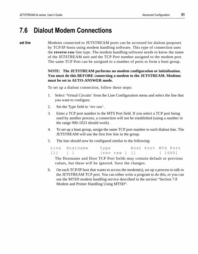
������������� �������� �������� �� ���������%�,� ����� /$
ses es me ort. up.
at
g er in
. The
us
talk to can
1% '������������� �!!�����!�
������!� Modems connected to JETSTREAM ports can be accessed for dialout purpoby TCP/IP hosts using modem handling software. This type of connection usthe reverse raw line type. The modem handling software needs to know the naof the JETSTREAM unit and the TCP Port number assigned to the modem pThe same TCP Port can be assigned to a number of ports to form a hunt gro
NOTE: The JETSTREAM performs no modem configuration or initialisation. You must do this BEFORE connecting a modem to the JETSTREAM. Modems must be set to AUTO-ANSWER mode.
To set up a dialout connection, follow these steps:
1. Select ‘Virtual Circuits’ from the Line Configuration menu and select the line thyou want to configure.
2. Set the Type field to ‘rev raw’.
3. Enter a TCP port number to the MTS Port field. If you select a TCP port beinused by another process, a connection will not be established (using a numbthe range 900-1023 should work).
4. To set up a hunt group, assign the same TCP port number to each dialout lineJETSTREAM will use the first free line in the group.
5. The line should now be configured similar to the following:
The Hostname and Host TCP Port fields may contain default or previovalues, but these will be ignored. Save the changes.
6. On each TCP/IP host that wants to access the modem(s), set up a process tothe JETSTREAM TCP port. You can either write a program to do this, or you use the MTSD modem handling service described in the section “Section 7.8Modem and Printer Handling Using MTSD“.
Line Hostname Type Host Port MTS Port[1] [ ] [ rev raw ] [ ] [ 1000]

/* �� ���������%�,� ����� ������������� �������� ��������
ing to nal
sten
u
S tion ).
field p.
e
set
ess to this
to or
1%1 ���� �����!��������� �!!�����!�
������!� You can set up bidirectional modem connections on an JETSTREAM port usthe bidir line type. This enables a modem connected to an JETSTREAM portbe used for dialin and dialout purposes simultaneously. To set up a bidirectiomodem connection, follow these steps:
1. On the network host targeted by the dialin connection, assign a TCP port to lifor the connection.
2. On the JETSTREAM, select Virtual Circuits from the Line Configuration menand select the line you want to configure.
3. Set the line type to bidir .
4. To enable the dialout process, a TCP port number must be added to the ‘MTPort’ field. If you select a TCP port being used by another process, a connecwill not be established (using a number in the range 900-1023 should be safe
5. To set up a hunt group, specify the same TCP port number in the ‘MTS Port’ of each bimodem line. The JETSTREAM will use the first free line in the grouYou can create up to eight hunt groups.
6. For the dialin process, specify the TCP port assigned on the target host in th‘Host Port’ field.
7. Enter the name of the target host in the ‘Hostname’ field.
8. The line should now be configured similar to the following:
Save the changes.
9. Select Line Settings from the Line Configuration menu. For each dialin line, the ‘Modem’ field to on. Configure the line settings as required.
10. On the TCP/IP host targeted by the dialin connection, you must set up a procreceive data on the chosen TCP port. You can write your own program to door you can use the MTSD modem handling service described in the section Section 7.8 Modem and Printer Handling Using MTSD.
11. On each TCP/IP host which wants to use the dialout facility, set up a processtalk to the JETSTREAM TCP port. You can either write a program to do this,you can use MTSD.
Line Hostname Type Host Port MTS Port[1] [p lato ] [b idi r ] [2000] [ 900]

������������� �������� �������� �� ���������%�,� ����� /+
s, nks
.
hey scos. le).
riate
voke rtest
1%2 �������!��� �!�� �8�!���!,�5��!,����'
MTSD is a host-based modem/print handling utility which enables applicationlike kermit, uucp and lp, to use JETSTREAM ports as local device nodes. It lipseudo devices to JETSTREAM ports via a ‘link file’ on the host machine. MTSD can be used to provide the following services:
• Dialin modem handler
• Dialout modem handler
• bidirectional modem link
• Printer server
These modes can be invoked from the command line or set up to start automatically at boot (by editing UNIX start-up files). Thereafter the user canread/write to the link file created by the process.
MTSD can be installed on any TCP/IP host running SCO UNIX/ XENIX, INTERACTIVE UNIX, UNIX SVR4, IBM AIX RS/6000 or RISCOS.
1%2%$ (!������!,����'
You will find MTSD on the Supplemental disk supplied with the JETSTREAMTo install MTSD, follow these steps:
1. Tar the contents of the diskette onto the TCP/IP host.
2. The diskette contains an executable for each supported operating systems. Tare called mtsd.sco, mtsd.xen, mtsd.isc, mtsd.svr4, mtsd.rs6000 and mtsd.riCopy the appropriate executable file to the hard disk (into /usr/bin, for examp
3. If, for any reason, you need to compile the makefile yourself, use the appropmake command from the list below:
Make sco
make xen
make isc
make svr4
make rs6000
make r iscos
MTSD is now installed. The modes of operation and the commands used to inthem are described below. All MTSD commands can be abbreviated to the sho

/. �� ���������%�,� ����� ������������� �������� ��������
d by
tte.
e
evice
p a
unambiguous form. A comprehensive menu-driven help utility can be accessetyping mtsd -help in the directory in which MTSD is resident. The help utility provides information on each mode of operation and each command option. MTSD outputs a software version number when run.
The MTSD source code is provided on the JETSTREAM supplementary diskeUse the code to compile MTSD on other operating systems.
Note Any changes to the source code are not supported by Specialix.
1%2%* ��� ����'����!�������8�!���!,�� �����
On dialin connections, MTSD will now, by default, start a login process on a pseudo tty directly (rather than set up a getty to spawn a login process on thlinkfile).
Instead of reopening the same pseudo tty, MTSD selects the next available din the list p01->pff->q01->qff->r01->rff->p01.
To set up a process to receive data on the TCP port assigned to the dialin connection, use the following command:
Where:
<tcpportno> is the TCP port to accept connection on the host.
The section “Section 7.5 Dialin Modem Connections” describes how to set udialin connection on a JETSTREAM port.
(!>�#�!,���!�!0��,�!�� �����
On dialin connections, MTSD by default invokes /bin/login with ‘sane’ tty settings. There are a set of options which enable you to invoke a non-login process.
These are as follows:
-path <pathname>
pathname of required process (e.g. /bin/cat).
-prog <program_name>
mtsd -d ia l in -hostport<tcpportno>

������������� �������� �������� �� ���������%�,� ����� //
d by oked
tmp
f the n the tory tsd/
fore e
ou
name of program (e.g. cat).
-parg1...9 <argument>
enable you to specify a maximum of 9 arguments.
-termfile <filename>
the name of the file containing the termio settings (in stty -g format) to be usethe pseudo tty instead of the default ‘sane’ settings. After completion of the invprocess, the ‘sane’ tty settings will be resumed.
-nologin
defines the process as a USER_PROCESS for the purpose of updating /etc/uand wtmp files correctly.
An example is given below:
mtsd -dialin -hostport <tcpportno> -path /bin/cat -prog cat -parg1 <filename> -nologin
0���!���������!��!������!���!!�����!�
On dialin connections, the -ttyname option will enable you to allocate a specificname to the selected pseudo tty. This name will then be displayed, instead optty device name, when commands such as ps, tty and who are issued. Wheconnection is established, the pseudo tty will be removed from the /dev direcand replaced by the specified ttyname. This will be recorded in the file /etc/mttyname enabling MTSD to recover the pseudo tty should the system crash.
Note You may have to create the /etc/mtsd/ directory.
0!���!,� ������!��!������!���!!�����!�
There is a mechanism which prevents a network connection being closed beall data has been received and acknowledged by the other end. It is called thSO_LINGER mechanism
The -nolinger option enables you to disable the SO_LINGER mechanism. If yare experiencing problems with the SO_LINGER mechanism, try using the -drain option to extend the timeout before resorting to the -nolinger option.

/ �� ���������%�,� ����� ������������� �������� ��������
ult.
file alout
tty
.
up
ion er
port ad
ut has
'����!��!�� �5!���9�.
On dialin connections under SVR4, the line discipline module is added by defaThe relevant option is -noldterm.
1%2%+ ��� ����'�������������8�!���!,�� �����
MTSD can be used to set up a dialout process to read/write from a named linkand connect to the TCP port assigned to the JETSTREAM port. To set up a diprocess, use the following command:
Where:
tcpportno is the TCP port number assigned to the JETSTREAM port. Ifthis TCP port is assigned to a hunt group, MTSD will use the first freeport in the group.
filename is the name you want to assign to the file linked to the pseudobeing used for the process.
hostname is the hostname or internet address of the JETSTREAM unit
The section “Section 7.6 Dialout Modem Connections” describes how to set dialout connections on JETSTREAM ports.
For dialout connections, a -noclose option is provided which will hold the pseudotty open after the network connection has closed, thus avoiding any connectclosing issues. The -inactivity option enables you to set a period in minutes aftwhich the pseudo tty should be closed regardless.
1%2%. ��� �������� �����!���������8�!���!,�� �����
MTSD can be used to set up a dialin process to receive data on the host TCPnumber and read/write to a named link file, then start a dialout process to refrom the link file and connect to the JETSTREAM TCP port.
Note that the linkfile will be unlinked during dialin operation to prevent a dialoprocess being started. The link will be restored as soon as the dialin processcompleted.
To start this process, enter the following command:
mtsd -dia lout/ -pr inter -mtsname <hostname> -mtsport <tcpportno> - l inkf i le <f i lename>

������������� �������� �������� �� ���������%�,� ����� /1
P
e
.
set
ed
.
up,
re
Where:
tcpportnoA is the TCP port assigned to the JETSTREAM port. If the TCport is used by a hunt group, MTSD will use the first free port it finds.
tcpportnoB is the TCP port number assigned on the TCP/IP host for thdialin connection.
filename is a name you want to assign to the link file.
hostname is the hostname or internet address of the JETSTREAM unit
The section “Section 7.7 bidirectional Modem Connections” describes how toup a bidirectional connection.
NOTE: When running uugetty using the MTSD bidirectional facility, you must set it up so that it doesn’t send the ‘login:’ prompt until the connection has been established. If you are running SCO UNIX & XENIX, this is performed by MTSD.
1%2%/ ��� ����� �!��8�!���!,�� �����
MTSD can be used to start a print handling process to read/write from a namlink file and connect to the TCP port assigned to the printer port. To start thisprocess, enter the following command:
Where:
hostname is the hostname or internet address of the JETSTREAM unit
tcpportno is the TCP port assigned to the JETSTREAM port that the printer is attached to. If this TCP port number is assigned to a hunt grothe first free port in the group will be used.
newline is an optional argument which will perform newline to carriagereturn newline mapping.
filename is a name you want to assign to the link file. You must configuyour UNIX printer to use this file as the print device.
The section “Section 7.4 Remote Printing Using Host-Based Print Handling Software” describes how to set up a remote printing connection.
mtsd -both -mtsport <tcpportnoA> -hostport <tcpportnoB> -l ink <f i lename> -mtsname <hostname>
mtsd -pr int -mtsname <hostname> -mtsport <tcpportno> [ - newl ine] - l inkf i le <f i lename>

/2 �� ���������%�,� ����� ������������� �������� ��������
1%2% 6����������'������!�������!�
���*��# ��%�**�*�����%����9����������-��������$
���'� ����!��7����! ��!����!
-both|bidirectional Select bidirectional operation
-debug If you include this argument, brief debug information will be displayed.
-dialin|in select dial-in operation
-dialout|out select dial-out operation
-drain n This option enables you to specify the number of seconds before a connection is closed down. The default is 5 seconds. If you find that files or print jobs are being truncated, increase this value.
-hostport<tcpportno>
TCP port to accept connection on host
-inactivity inactivity before connection is closed
-linkfile|file select linkfile name
-mtsname|host<hostname>
select JETSTREAM unit to connect to
-mtsport<tcpportno>
TCP port assigned to hunt group on JETSTREAM
-newline|mapping Enable NL to CRNL mapping on output
-noclose keep network connection open
-noldterm|nolinedisc
Do not push on ‘ldterm/linedisc’
-nolinger Do not invoke SO_LINGER
-nologin invoke a program other than a login

������������� �������� �������� �� ���������%�,� ����� /4
-opens n This argument enables you to specify the number of times (after a one-second interval) that MTSD attempts to open the master pseudo tty. By default, MTSD makes 10 attempts. You will need to increase this value if the following error message is displayed:
MTSD: re-open of master pt ty fa i led.
-pargx <argument> arguments; x is in the range 1-9
-path <program_path>
program’s path
-print select print operation to JETSTREAM
-prog<program_name>
program to be invoked
-reconnects n This option enables you to specify the number of times (after a two second interval) that MTSD will try to establish a connection with the JETSTREAM. The default is 50. You will need to increase this value if you see the following message:
MTSD: reconnect ion tr ies exhausted - abort ing.
-retry n This option enables you to specify the number of times (after a one-second interval) that MTSD attempts to read the master pseudo tty before deciding that no process is active. By default, MTSD makes 5 attempts. You will need to increase this value if you find that connections are being closed whilst still active. If you find that connections are being reopened too quickly, set retry to 0.
-termfile termio settings file to use
-ttyname specify a fixed tty name
-verbose Include this argument if you want to receive full debug information.

) �� ���������%�,� ����� ������������� �������� ��������
ction 0).
1%4 ��>� ������!��� �!!�����!
������!� A reverse telnet connection enables a TCP/IP host to establish a login conneon a machine external to the network via an JETSTREAM port (see Figure 1The JETSTREAM will effectively be transparent.
F�,� ��#& ����-���*��� � �����*�������%�,� �����
NON-TCP/IP
Async port
TCP/IP HOST
JETSTREAM
Ethernet
Serial
Reverse Telnet
HOST
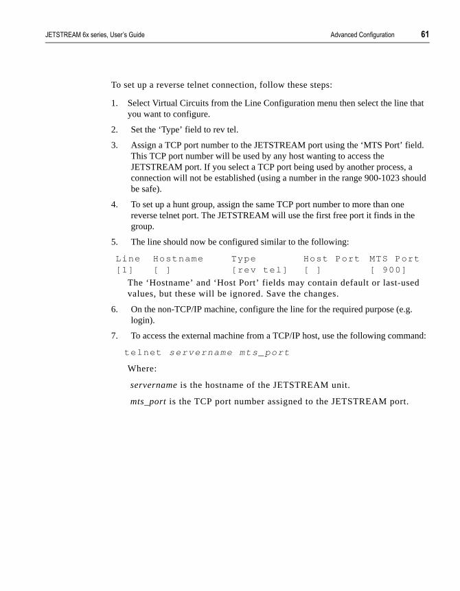
������������� �������� �������� �� ���������%�,� ����� $
at
d.
ould
.
and:
To set up a reverse telnet connection, follow these steps:
1. Select Virtual Circuits from the Line Configuration menu then select the line thyou want to configure.
2. Set the ‘Type’ field to rev tel.
3. Assign a TCP port number to the JETSTREAM port using the ‘MTS Port’ fielThis TCP port number will be used by any host wanting to access the JETSTREAM port. If you select a TCP port being used by another process, aconnection will not be established (using a number in the range 900-1023 shbe safe).
4. To set up a hunt group, assign the same TCP port number to more than onereverse telnet port. The JETSTREAM will use the first free port it finds in the group.
5. The line should now be configured similar to the following:
The ‘Hostname’ and ‘Host Port’ fields may contain default or last-usedvalues, but these will be ignored. Save the changes.
6. On the non-TCP/IP machine, configure the line for the required purpose (e.glogin).
7. To access the external machine from a TCP/IP host, use the following comm
te lnet servername mts_port
Where:
servername is the hostname of the JETSTREAM unit.
mts_port is the TCP port number assigned to the JETSTREAM port.
Line Hostname Type Host Port MTS Port[1] [ ] [ rev te l ] [ ] [ 900]

* �� ���������%�,� ����� ������������� �������� ��������
rse vent bles M, ing
1%$) �������� ���
�������� �����!:���The remote access features of the JETSTREAM (remote configuration, reveand printer line types) enable access to the unit from other hosts. To help preunauthorised access, the JETSTREAM includes a security feature which enayou to restrict incoming connections to those hosts ‘known’ to the JETSTREAi.e. those hosts defined in the host table. This feature is enabled/disabled usthe ‘Security’ option on the Network Configuration menu.
������������� �������� �������� �� ���������%�,� ����� +
and M NMP B ll
le 2
t
I
to
LI
ds).
1%$$ �������&��3� #���!�,���!��� �������
The Simple Network Management Protocol (SNMP) is a protocol for access control of network management information on TCP/IP networks. JETSTREAprovides an SNMP agent, able to respond to SNMP requests generated by SManagers. The JETSTREAM implementation of SNMP is compatible with MIII (RFC 1213) as specified by the SNMP SMI document (RFC1155). For a fudescription of SNMP, refer to your SNMP documentation.
Enterprise-specific parameters are defined by the Specialix Private MIB. Tabbelow gives a summary of the objects defined by the Specialix MIB. For full details, refer to Appendix E (Specialix Private MIB Definitions).
1%$$%$ (������!��!,������������&�������� �
A separate copy of the JETSTREAM software, containing SNMP support, is supplied on diskette. Download this version to the JETSTREAM using the nerebooting process. See Section 8.2 Net Rebooting.
The JETSTREAM SNMP Agent will only provide information to hosts definedby an SNMP community. You can create up to four communities using the CLcommand add community; you can remove communities using the command delete community.
SNMP Trap messages generated by the JETSTREAM will only be broadcasthosts defined by SNMP Trap communities. You can create up to four trap communities using the CLI command add trap; you can remove trap communities using the command delete trap.
NOTE: The JETSTREAM generates no enterprise-specific traps.
You can configure the SNMP sysContact and sysLocation objects using the Ccommands set contact contact_name and set location location.
These commands are described in full detail in Chapter 11 (The CLI comman

. �� ���������%�,� ����� ������������� �������� ��������
Table 2Summary of Objects Defined in the Specialix Private MIB
OBJECT NAME
ADDRESS TYPE PERMISSIONS
ServerInfo 1.3.6.1.4.1.667.1.1 Aggregate not-accessiblefreeSpace 1.3.6.1.4.1.667.1.1.1 Guage read-onlyswVersion 1.3.6.1.4.1.667.1.1.2 DisplayString read-onlyserverName 1.3.6.1.4.1.667.1.1.3 DisplayString read-onlydomaiName 1.3.6.1.4.1.667.1.1.4 DisplayString read-onlyportsInfo 1.3.6.1.4.1.667.1.2 Aggregate not-accessibleportsNumber 1.3.6.1.4.1.667.1.2.1 INTEGER read-onlyportsInfoTable 1.3.6.1.4.1.667.1.2.2 Aggregate not-accessibleportsInfoEntry 1.3.6.1.4.1.667.1.2.2.1 Aggregate not-accessibleportId 1.3.6.1.4.1.667.1.2.2.1.1 INTEGER read-onlyterminalType 1.3.6.1.4.1.667.1.2.2.1.2 INTEGER read-writebaudRate 1.3.6.1.4.1.667.1.2.2.1.3 INTEGER read-writedataBits 1.3.6.1.4.1.667.1.2.2.1.4 INTEGER read-writeparity 1.3.6.1.4.1.667.1.2.2.1.5 INTEGER read-writestopBits 1.3.6.1.4.1.667.1.2.2.1.6 INTEGER read-writepages 1.3.6.1.4.1.667.1.2.2.1.7 INTEGER read-writedefaultUser 1.3.6.1.4.1.667.1.2.2.1.8 INTEGER read-writevalidUser 1.3.6.1.4.1.667.1.2.2.1.9 INTEGER read-writemodem 1.3.6.1.4.1.667.1.2.2.1.10 INTEGER read-writeflowControl 1.3.6.1.4.1.667.1.2.2.1.11 INTEGER read-writelineType 1.3.6.1.4.1.667.1.2.2.1.12 INTEGER read-writehostPort 1.3.6.1.4.1.667.1.2.2.1.13 INTEGER read-writemtsPort 1.3.6.1.4.1.667.1.2.2.1.14 INTEGER read-writehost 1.3.6.1.4.1.667.1.2.2.1.15 INTEGER read-writepinDCD 1.3.6.1.4.1.667.1.2.2.1.16 INTEGER read-onlypinDTR 1.3.6.1.4.1.667.1.2.2.1.17 INTEGER read-onlypinRTS 1.3.6.1.4.1.667.1.2.2.1.18 INTEGER read-onlycharSends 1.3.6.1.4.1.667.1.2.2.1.19 Counter read-writecharReceiveds 1.3.6.1.4.1.667.1.2.2.1.20 Counter read-write

������������� �������� �������� ��������������� ����� /
eed
� � � - � � � 6
�����������!��� ����!
2%$ (!� �������!
This chapter describes the other major tasks, apart from installing and configuring the JETSTREAM, that you - as the system administrator - may nto perform. It is divided into the following sections:
• 8.2 Net Rebooting...... page 66
• 8.3 Upgrading System Software...... page 66
• 8.4 Downloading Terminal Definitions...... page 66
• 8.5 BOOTP...... page 70
• 8.6 Adding a Boot Host...... page 75
• 8.7 Deleting a Boot Host...... page 75
• 8.8 Rebooting the JETSTREAM...... page 76
• 8.9 Resetting the Server to Factory Defaults...... page 77
• 8.10 Remote Configuration...... page 77
• 8.11 Save/Restore Configuration (to a remote host)...... page 77
• 8.12 Lost Password...... page 78

��������������� ����� ������������� �������� ��������
e 0,
are,
d e e
ave
M.
ad
n’t
lled, i.
2%* &����������!,
Net rebooting is a process which enables you to download files to the JETSTREAM from another TCP/IP host (boot host) at bootup. This has two important applications:
• Upgrading system software - downloading software upgrades avoids having to replace ROM chips. See Section 8.3.
• Downloading terminal definitions - enables you to use Full Screen mod(menus) on more terminal types than those defined by default (Wyse6Ansi, VT100). See Section 8.4.
2%+ 5�, ���!,������������3� �
To set up a net rebooting environment and upgrade your JETSTREAM softwfollow these steps:
1. Decide which TCP/IP host you are going to use as the boot host. It must be aUNIX machine and must have tftp enabled. If you already have a boot host define(for downloading terminal definition files), you can use this host. You can defintwo boot hosts if you want a good safeguard against the first host being off-linwhen required.
2. Tar the file mtsprom from the upgrade diskette onto the boot host. This is the boot file.Make sure it has global read/execute permission for its entire path. If you hdefined two boot hosts, copy the software onto both of them.
3. Define the boot host and boot file (if not already defined) using the Add Boot Host feature (see the section Section 8.6 Adding a Boot Host).
4. Enable net rebooting and reboot the JETSTREAM using the Reboot Server feature (see the section Section 8.8 Rebooting the JETSTREAM). If the JETSTREAM can’t download the boot file for any reason, it will boot from RO
2%. '�3!�����!,��� ��!���'���!����!�
This section tells you how to set up a net rebooting environment and downloterminal definitions.
All terminal types can be used on the JETSTREAM. Terminal types which aredefined on the JETSTREAM, however, are unable to use Full Screen mode (menus) and may not be able to page through sessions properly. When instathe JETSTREAM has three defined terminal types - Wyse60, VT100 and Ans

������������� �������� �������� ��������������� ����� 1
d up
ing
lied
ow
d ly
al c/
a
ion
e
If you are not using, or can’t emulate, any of these terminal types, you can adto three additional terminal definitions using the JETSTREAM Extraterms feature. The terminal definitions are downloaded from another TCP/IP host usthe net rebooting process.
Three sample terminal definitions are supplied on the Supplemental disk suppwith the JETSTREAM. These areTVI950, IBM3161 and Adds Viewpoint.
To set up a net rebooting environment and download terminal definitions, follthese steps:
1. Decide which TCP/IP host you are going to use as the boot host. It must be aUNIX machine and must have tftp enabled. If you already have a boot host define(for upgrading software), you must use this host (terminal definition files will onbe downloaded from boot host 1).
2. Create the required terminal definition files on the boot host (see the sectionSection 8.4.1 Creating Terminal Definition Files), or load the sample files provided on diskette (see the section Section 8.4.2 Using the Sample TerminDefinition Files). Terminal definition files must be installed in the directory /etmts on the boot host. Use the names term1, term2 and term3.
Note: if you are using tftp with the secure option, i.e. “tftpd -s /tftpboot”, create/tftpboot/etc/mts/ directory and place the term files in there.
3. Enable the Extraterms feature (see the section Section 8.4.3 Enabling the Extraterms Feature).
4. Define the boot host (if not already defined) using the Add Boot Host feature (see the section Section 8.6 Adding a Boot Host).
5. Reboot the JETSTREAM using the Reboot Server feature (see the section Section 8.8 Rebooting the JETSTREAM).
2%.%$ ����!,��� ��!���'���!����!������
To create new terminal definition files, you need to copy and edit the informatfrom the terminfo database.
1. On the boot host, change directory to /usr/lib/terminfo/x (where x is the first letter of the required terminal type). For a Wyse50, for example, you would enter thcommand cd /usr/lib/terminfo/w.
2. The termcap files are compiled, so use the command infocmp termfile to read the required file (for example: infocmp wy50).
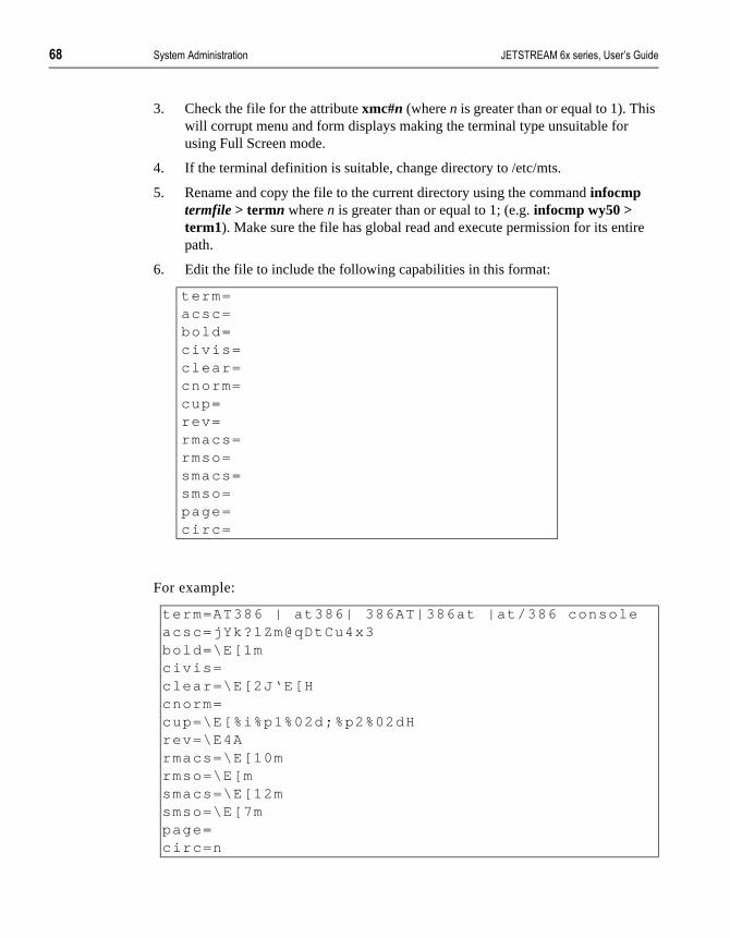
2 ��������������� ����� ������������� �������� ��������
ire
3. Check the file for the attribute xmc#n (where n is greater than or equal to 1). Thiswill corrupt menu and form displays making the terminal type unsuitable for using Full Screen mode.
4. If the terminal definition is suitable, change directory to /etc/mts.
5. Rename and copy the file to the current directory using the command infocmp termfile > termn where n is greater than or equal to 1; (e.g. infocmp wy50 > term1). Make sure the file has global read and execute permission for its entpath.
6. Edit the file to include the following capabilities in this format:
For example:
term=acsc=bold=civ is=clear=cnorm=cup=rev=rmacs=rmso=smacs=smso=page=circ=
term=AT386 | at386| 386AT|386at |at /386 consoleacsc=jYk?lZm@qDtCu4x3bold=\E[1mciv is=clear=\E[2J‘E[Hcnorm=cup=\E[%i%p1%02d;%p2%02dHrev=\E4Armacs=\E[10mrmso=\E[msmacs=\E[12msmso=\E[7mpage=circ=n

������������� �������� �������� ��������������� ����� 4
map ndard
e the
ld s. The ge’ d in
e cute
m
NOTE: As you can see from the example, capabilities which are not defined in the terminfo file must still be included (albeit with no value). Each entry has an 80 character limit.
On some versions of UNIX, some of the capabilities are appended with a millisecond delay (of the form $<n>). These are ignored by JETSTREAM and can be left out.
The ‘acsc’ capability, if defined, contains a list of character pairs. These pairs the characters used by the terminal for graphics characters to those of the sta(VT100) character set.Include only the following character pairs:
jx, kx, lx, mx, qx, tx, ux and xx
(where x must be substituted by the character used by the terminal). These arbox-drawing characters used to display the forms and menus of Full Screen mode. They must be entered in this order.
The last two capabilities will not be found in the terminfo file. In the ‘page’ fieyou must enter the escape sequence used by the terminal to change screen‘circ’ field defines whether the terminal can use ‘previous page’ and ‘next pacontrol sequences. It must be set to ‘y’ or ‘n’. These capabilities can be founthe documentation supplied with the terminal.
2%.%* 5��!,�������������� ��!���'���!����!������
Tar the sample files from the Supplemental disk onto the boot host. They arecalled ET.tvi950, ET.addsvp and ET.ibm3161. Copy them to/etc/mts using thfilenames term1, term2 and term3. Make sure they have global read and exepermission for their entire path.
2%.%+ �!����!,������� ��� �������� �
������ ��� �� From the Network Configuration menu, select ‘Extraterms’. The following forwill be displayed:
Toggle the setting to ‘on’.
ExtratermsSet Extraterms [of f ]

1) ��������������� ����� ������������� �������� ��������
4.5
ese the
at do
t a ess,
t,
ined
d
AM. le
2%.%. 5��!,�'�3!��������� ��!���'���!����!�
������!� Terminal type is selected per line through the Line Settings form (see SectionLine Settings). In the ‘Terminal’ field, use the spacebar to cycle through the available terminal definitions. These will include term1, term2 and term3. Thdefinitions default to Wyse60 unless replaced by a downloaded definition of same name.
HINT: If, when using a downloaded terminal definition, you have problems using arrow keys, you can use Ctrl-K, Ctrl-J, Ctrl-H and Ctrl-L for up, down, left and right.
2%/ @77��
BOOTP is a useful tool for auto-configuring one or more JETSTREAM units bootup, and is particularly useful for multiple installations. This enables you toall JETSTREAM configuration in one BOOTP file, rather than configure eachJETSTREAM unit manually.
On bootup, the JETSTREAM, having only its ethernet address, will broadcasrequest to BOOTP servers, for its network configuration details (internet addrsubnet mask, etc.).
BOOTP should not be confused with:
a) net rebooting, which downloads the JETSTREAM software from a boot hosand b) save/restore configuration, which saves/restores user and port configurationinformation to/from a boot host.
BOOTP can be used to download instructions for: net rebooting, restore configuration, extraterms, and set security. Details of these features are explain this Manual.
The JETSTREAM implementation of BOOTP is compatible with RFCs 951 an1497.
2%/%$ 8�3����������@77��
In the BOOTPTAB file on the host, add the Ethernet address of the JETSTRE(On UNIX systems the BOOTPTAB file is usually file /etc/bootptab). An exampof a BOOTPTAB file is at Figure 11.

������������� �������� �������� ��������������� ����� 1$
e
the
ay. d
he
The JETSTREAM - on reboot or power-up - will always transmit a BOOTP request across the network. If a reply is received from a BOOTP host, the JETSTREAM will boot using the BOOTPTAB file configuration information.
Whether or not a BOOTP reply is received, the JETSTREAM will continue toboot, either via net rebooting (if enabled) or, if not, from its own PROM.
2%/%* ����@77����@�����
In the BOOTPTAB file of the responding host(s), the following fields should bset:
ht (hardware type) set to 1 (=10Mb ethernet).ha (hardware address) set to the ethernet address of the JETSTREAM.ip (internet address) set to internet address of the JETSTREAM.sm (subnet mask) set to the subnet mask of the JETSTREAM.bf (bootfile name) set to the name of the file on the host to boot from.ds (domain servers) ip address of up to two nameservers.
gw (gateway) ip address of a single static gatewayhn (hostname).vm=rfc1048
Notes on the above:
1. If the subnet mask (sm) has not been explicitly specified by a BOOTPREPLYpacket, it will be derived from the class of internet address.
2. If domain name servers are specified their port number will always be set to default for a name server (53).
3. If you include the gw (gateway) flag you are configuring a single static gatewThe JETSTREAM will ignore RIP packets and the gateway you have specifiewill be permanent; it will also be the only available gateway.
4. We suggest you always enter the fields ip, sm and bf. If in doubt enter all of tfields.

1* ��������������� ����� ������������� �������� ��������
are
l)
In addition there are Specialix-specific fields; Table 3 lists these fields. They optional:
���*��:$
Notes:
1. The speech marks, e.g in “iris”, are mandatory.
2. The server name option (T134) should be specified.
3. If the broadcast address (T128) has not been explicitly specified by a BOOTPREPLY packet, it will be calculated from the internet address and thesubnet mask.
Specialix bootp tag format Description
T128=0xc04192ff network Broadcast address (hexadecima
T129="/etc/mts/snmpprom" second bootfile (quoted string);see Section 8.5.4
T130="yes" autoreboot - Y/N
T131="yes" extraterms - Y/N
T132="no" security - Y/N
T133="yes" autorestore of configuration - Y/N
T134="iris" bootp server hosts name
T135="boot2" second boot hosts name; see Section 8.5.4
T136=0xc04192fe second boot host's IP address (hexadecimal); see Section 8.5.4

������������� �������� �������� ��������������� ����� 1+
ts1
An example of a bootptab file is shown in Figure 11:
F�,� ��##
���-*�
����-����%�*�
Notes on Figure 11:
1. if you have multiple JETSTREAMs, list them at the bottom of the file; so cusmis the first (as in the example) and your second JETSTREAM is cusmts2.
2. So that all JETSTREAMs that you list use the same BOOTP information, terminate the lines detailing each JETSTREAM with the same syntax tc=name (in the example above tc=common).

1. ��������������� ����� ������������� �������� ��������
e
mple
EAM
2%/%+ '������!,�����@77�������
You cannot disable BOOTP; however, you can disable the transmission of thBOOTP reply packet back to the JETSTREAM.
To disable this transmission, place a hash # before the last line; so in the exain Figure 11, the last line would read:
# cusmts2:ht=1:ha=0080ba000025:ip=192.101.34.194:tc=common:
2%/%. 5��!,�@77���3����������!�� ��8���The following Specialix defined bootp tags can be used to configure the JETSTRto download a bootfile image from a secondary host:
T129="u/mp" - second bootfile (quoted string) T135="rrdc" - second boot hosts name (quoted string) T136=0xc06522c3 - second boot host's IP address (must be in hexadecimal)
F�,� ��#0�
���-*������-����
%�*��%� ���
������� ������

������������� �������� �������� ��������������� ����� 1/
nu
oot
a t
nu
2% ����!,���@����8���
������������ Select ‘Boot Hosts’ from the Network Configuration menu; the Boot Hosts mewill be displayed:
Select ‘Add Boot Host’ and the host table will be displayed:
Select the required host. You will be prompted to enter the pathname of the bfile:
Enter the full pathname of the boot file (60 characters maximum) and press <return>. Use the <del> key to backspace if necessary. If you are setting up boot host for downloading terminal definitions only, you must still enter a boofile (it will be ignored and the JETSTREAM will reboot from ROM).
2%1 '�����!,���@����8���
��������������� Select ‘Boot Hosts’ from the Network Configuration menu; the Boot Hosts mewill be displayed:
Select ‘Delete Boot Host’ to list your boot hosts:
Boot HostsAdd Boot HostDelete Boot Host
Hostssocratesar is tot leplatosophocleshomerpythagoras
Fi lename:
Boot HostsAdd Boot HostDelete Boot Host
Delete Boot Hostssocrates: /etc/mts/mtspromhomer: /etc/mts/mtsprom

1 ��������������� ����� ������������� �������� ��������
ill
ot
l, it
Select the boot host that you want to delete. You will be asked to confirm thedeletion:
Type ‘y’ to delete the boot host, ‘n’ to cancel the command.
2%2 �������!,��������������
����!������;�
�����
From the Network Configuration menu select ‘Reboot’. The following menu wbe displayed:
Select ‘Set Net Rebooting’; the following form will be displayed.
For rebooting from ROM and downloading terminal definition files, net rebooting must be set to ‘off ’. For rebooting from a boot file, it must be set to‘on’. Quit and save.
Select ‘Reboot Server’. You will be asked to confirm the action:
Type ‘y’ and the JETSTREAM will reboot.
When net rebooting, the JETSTREAM will continue trying to download the bofile until successful or until you press a key on the console to interrupt. This caters for the situation where the boot host takes longer to boot than the JETSTREAM after a power break. If boot host 1 fails, the JETSTREAM will attempt to access boot host 2. If the JETSTREAM fails to find a boot file at alwill eventually timeout and reboot from ROM.
NOTE: As installed from SCO, TCP/IP for SCO XENIX will not allow JETSTREAM to reboot across the network. This problem can be resolved by a simple modification to the file /etc/inetd.conf. The line that reads:
t f tp dgram udp wai t sync /etc/ t f tpd t f tpd
should be changed to:
t f tp dgram udp wai t root /etc/ t f tpd t f tpd
Conf i rm Delete Boot Host ‘socratesr ’ (y/n)
RebootReboot ServerSet Net Reboot ing
Set Net Reboot ingSet Net Reboot ing [of f ]
Conf i rm Reboot Server (y/n)

������������� �������� �������� ��������������� ����� 11
is nts, rk
is sly. de if
wing
2%4 �������!,������� >� ��������� ��'�������
���������� � This feature enables you to reset the JETSTREAM to its default settings. Thwill clear all configuration data entered by the admin user, and all user accouexcept the default admin user, will be deleted. Select ‘Reset’ from the NetwoConfiguration menu; you will be asked to confirm the reset:
Type ‘y’ to reset the JETSTREAM, ‘n’ to cancel the command.
2%$) ������� �!��,� ����!
You can configure the JETSTREAM unit remotely by starting a telnet to its standard telnet port (23) from another host on the network. No configuration necessary to use this feature and two such sessions can be run simultaneouYou will be prompted for a login name and password. All functionality will beavailable except the ability to access other hosts. You can use Full Screen moyou use a terminal type defined on the JETSTREAM.
The JETSTREAM includes a security feature which enables you to restrict incoming connections to only those hosts defined in the host table. This is described in Section 7.10 Set Security.
2%$$ ��>�:����� �� �!��,� ����!
<����� ����������=
��>�;� ���� � JETSTREAM configuration information can be saved to a remote host, and subsequently restored, using the CLI commands save and restore. The folloinformation will be saved:
User Profiles
Port Configuration
Host Table
Gateways
Conf irm Reset To Factory Defaul ts (y /n)

12 ��������������� ����� ������������� �������� ��������
ion
ons fer
ging
n a
ou
red
use it
Fixed (hard-coded) data and JETSTREAM details will not be saved. Informatwill be saved to the file /etc/mts/config/servername on boot host 1 (where servername is the name assigned to the JETSTREAM unit). Most UNIX versiof TFTP require this file to exist and have global write permission before transcan take place.
2%$* 6��������3� �
If you are an admin user, and you forget your password, here is a way of logon without it. This can only be done on port 8 (the console port).
Reboot the JETSTREAM (power-cycle the unit).
When the unit has powered up and initialised itself, the power LED will turn orange for five seconds. During this time, type in the magic string (detailed oseparate release note (document number SP-US293)) and press <Return>.
This will set the admin password to <Return> for this login attempt only. Once yhave logged in, select a new admin password using the set user command.
If you find that you can’t type in the magic string within the 5 seconds, try mapping it to one of the function keys (not forgetting the carriage-return requiafterwards).
Note The magic string information (release note) should be kept in a secure place becaenables access to the JETSTREAM and your network without a password.

������������� �������� �������� /��������,� 14
who
� � � - � � � >
@��������,�
4%$ (!� �������!
This chapter shows basic usage of the JETSTREAM. It is provided for users, do not need to be familiar with system administration matters.
It is divided into the following sections:
• 9.2 Logging into the Server...... page 79
• 9.3 Modes of Operation...... page 80
• 9.3.1 Full Screen Mode...... page 81
• 9.3.2 Menus...... page 81
• 9.3.3 Forms...... page 81
• 9.3.4 Command Line Interface (CLI)...... page 83
• 9.4 Changing your Password...... page 83
• 9.5 Changing your Terminal Setup...... page 84
• 9.6 Changing your User Environment...... page 84
• 9.7 Logging Out...... page 85
Starting sessions on other machines from the JETSTREAM is described in Chapter 10 (Running Sessions).
4%* 6�,,�!,��!��������� >�
To be able to log in you must have a login name and password. The system administrator should have set these for you.

2) /��������,� ������������� �������� ��������
ted ng
r
rs,
on.
ng If ed
may
e
e for menu
• Switch your terminal on and press <return> to call the login prompt.
• Enter your login name and press <return>. If your line has been dedicato you, your login name will be displayed in brackets automatically, alowith the password prompt.
• At the password prompt, enter your password and press <return> (youpassword will not be displayed as you type it).
When you log in, the JETSTREAM is in Command Line mode. For admin usethe prompt is MTS#; for normal and restricted users it is MTS$.
If you are a restricted user, predefined sessions, set up by the system administrator, may start up automatically. If this is the case, go to Chapter 10(Running Sessions).
4%*%$ 6�,,�!,��!�>����������
Logging in via modem is the same as if you are directly connected to the JETSTREAM. An additional feature, however, is automatic baud rate detecti
If your terminal is set to a different baud rate to the JETSTREAM line, pressi<return> for the login prompt will display garbled characters or nothing at all.you send a line break (<break> key) the JETSTREAM will try the next line spesetting. Send breaks until the login prompt appears. At the slower speeds it take some time for a response.
NOTE: If you do change the line speed by sending breaks, the following messagwill be displayed at login:
Warning: Baud Rate Changed to new_speed
Set the line speed using the set line command, as follows:
set l ine n speed new_speed
4%+ ���������7�� ����!
The JETSTREAM has two modes of operation: Full Screen Mode (FSM) - thmenu system - and the Command Line Interface (CLI). The CLI is designed more experienced users. Normal and restricted users may prefer to use the system.

������������� �������� �������� /��������,� 2$
.To ing
text-
ions.
.
the to
s of
y t,
4%+%$ ������� ��!�����
Full Screen mode is a menu system, designed for easy access to commandsenter Full Screen mode, type screen and press <return>. The main menu will bedisplayed. For normal and restricted users the main menu contains the followoptions:
For admin users, the complete main menu will be displayed:
At the top of the screen is a banner which contains your username, your linenumber and the current version of software. At the foot of the screen is a consensitive help line which describes how to move around and select menu opt
To exit Full Screen mode, select ‘Command Line Mode’ from the main menu
4%+%* ��!��
Move up and down menus using the arrow keys, or by typing the first letter ofoption you want to select. Select a menu option by pressing <return>; returnthe previous menu by pressing <esc>. Type ‘?’ to display help information.
4%+%+ �� ��
Forms contain one or more data fields for you to complete. There are two typedata field:
• Fields in which you must type a value. These fields start off blank; thehave no default value. Some fields may require hex values. If in doubtype the help command (?) when in the field. Use the <del> key to backspace.
Main Menu
SessionsCommand Line Mode
Main Menu
SessionsCommand Line ModeUsersLine Conf igurat ionServer Conf igurat ionNetwork Conf igurat ion

2* /��������,� ������������� �������� ��������
be e
n. ey
t. .
n’t
• Fields where you select from a list of values. One of these values willentered as a default. You can cycle through the list of values using th<spacebar> key, or list them by typing ‘l’.
Movement between fields is controlled by the following keys:
<arrows> Use the arrow keys to move between fields in any directioIf a form covers more than one page, press the up arrow kon the first line of the form to display any previous page. Press the down arrow key on the last line of the form to display any next page.
<Tab> Moves you through fields on the same line, from left to righThe <backspace> key moves you in the opposite direction
<PgUp> If the form covers more than one page, you can use the <PgUp> key to display any previous page.
<PgDn> If the form covers more than one page, you can use the <PgDn> key to display any next page.
NOTE: On Ansi and VT100 terminals, the <PgUp> and <PgDn> keys won’t work unless they are programmed as ^[J and ^[K respectively (where ^[ = Escape).
There are two ways to exit a form:
<return> Use this key if you want to save the changes made to theform. The following menu will be displayed:
<esc> Use this key if you haven’t made any changes, or if you dowant to save the changes you have made. If you haven’t made any changes to the form, you will be returned to themenu. If you have made changes to the form, the followingmessage will be displayed:
Type ‘y’ to escape, ‘n’ to return to the form.
Quit FormSave And Exi t FormExi t Form Without Saving Changes
Changes Wil l Be Lost, Proceed? (y /n)

������������� �������� �������� /��������,� 2+
-
to
e to o
ser’ ord:
4%+%. ����!��6�!��(!�� �����< 6(=
Using the CLI you can enter JETSTREAM commands directly rather than through menu options. It is designed for the more experienced user. The Command Line has two features that make it extremely easy to use: contextsensitive help and command abbreviation.
4%+%/ 8���
The help key (?) can be pressed at any time to display the options available you. Look at the following example:
Notice how your original command is always preserved, so that you don’t havtype it in again. If you type ? at the CLI prompt, all the commands available tyour user level would be listed.
4%+% ����!����� �>�����!
You can use the shortest unambiguous abbreviation of any command. For example, the command:
set l ine 1 termtype wy60
could be entered as:
se l 1 te w
4%. ��!,�!,���� �����3� �
����!;�!� ����
����!�������
���
Select the Sessions menu from the main menu. From here, select ‘Set Up Uand then ‘Set Password’. You will be asked to enter your old (current) passw
MTS# set user . ?passwordlevelsessionswi tchMTS# set user .
Old Passwords:

2. /��������,� ������������� �������� ��������
ace if
ing r
ake
ve
ough
en
elect
You will then be asked to enter a new password:
The password can have up to eight characters. Use the <del> key to backspnecessary. You will be asked to repeat the password:
You will be returned to the Set Up User menu.
4%/ ��!,�!,���� ��� ��!��������
����!;�!� ����
����!�������
���
You are unlikely to need to change your terminal setup, especially while runnin Full Screen mode. If you do, remember to make the same changes to youterminal’s setup utility.
Changes to your terminal type or the number of video pages supported will teffect immediately. Other changes will take effect the next time you log in.
Don’t change the number of video pages your terminal supports while you hasessions running.
Select ‘Set Up Terminal’ from the Sessions menu. The following form will be displayed.
These are the default settings. In each field, use the <spacebar> to cycle thrthe available settings, or type ‘l’ to list them.
4% ��!,�!,���� �5�� ��!>� �!��!�
����!;�!� ����
����!�������
���
The only reason you should need to change your environment is if your screswitch character clashes with an application you are using in one of your sessions. From the main menu select the Sessions menu. From this menu, sthe Set Up User menu. Then select ‘Set Environment’.
Enter Passwords:
Re-enter Passwords:
Set Up TerminalSpeed Terminal Modem Flow Bits Par i ty Stop Pages[9600 ] [vt100] [of f ] [sof t ] [8] [none] [1] [3]
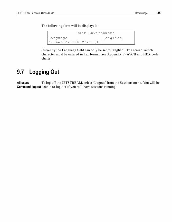
������������� �������� �������� /��������,� 2/
de
be
The following form will be displayed:
Currently the Language field can only be set to ‘english’. The screen switch character must be entered in hex format; see Appendix F (ASCII and HEX cocharts).
4%1 6�,,�!,�7��
������� ��
����!�����,���
To log off the JETSTREAM, select ‘Logout’ from the Sessions menu. You will unable to log out if you still have sessions running.
User Environment
Language [engl ish]Screen Switch Char [1 ]

2 /��������,� ������������� �������� ��������

������������� �������� �������� ������,��������� 21
ote he
ions
rt
� � � - � � � # &
��!!�!,�������!�
$)%$ (!� �������!
Users logged into the JETSTREAM can start up to four login sessions on remhosts. Sessions are started through the menu option ‘Sessions’ (or through tCLI). You can run multiple sessions simultaneously on the same host or on different hosts. You can switch between different sessions and between sessand the JETSTREAM using hot-key commands.
Admin and normal users can predefine sessions, even configure them to staautomatically on login to the JETSTREAM. The system administrator can predefine sessions for other users. Restricted users can only start sessions predefined for them.
This chapter is divided into the following sections:
• 10.2 Starting a Session...... page 88
• 10.3 Predefining Sessions...... page 89
• 10.4 Starting a Predefined Session...... page 90
• 10.5 Hot-key Commands...... page 91
• 10.5.1 Video Pages...... page 91
• 10.6 Resuming a Session...... page 92
• 10.7 Killing a Session...... page 92

22 ������,��������� ������������� �������� ��������
of your
can
y):
or 4
t to o
l
the er.
ou
$)%* ��� ��!,���������!
����!;�!� ����
����!����
���!��;� ��,�!
You can start up to four sessions on other TCP/IP hosts. The actual number sessions available is four minus the number of predefined sessions set up online.
If you have four predefined sessions, you will have no free sessions left. Youget around this by disabling one of your predefined sessions (in the ‘Set Sessions’ form, set the Type field to ‘off ’).
Select ‘Start telnet/rlogin’ from the Sessions menu. The following form will bedisplayed:
Complete the fields as follows (using the <del> key to backspace if necessar
• Type - this is the connection protocol you want to use: telnet (default)rlogin. The relative merits of these protocols are discussed in Chapter(Direct and Silent Login Connections).
• Hostname - the name or internet address of the machine that you wanaccess. You must have a login account on this machine. If you want taccess a machine in your local network which isn’t defined in the hosttable, you can only use the hostname if it can be resolved by a name server in your network. If you want to access a host outside your locanetwork, it is best to use the internet address.
• Termtype - the terminal type you enter here will be passed to the hostyou are trying to log into. The termtype must be a name recognised byhost. Your system administrator should be able to tell you what to ent
• Username (rlogin only) rlogin will pass your JETSTREAM username tothe target host. If your username on the target host is different, or if ywant to log in as somebody else, enter the required username here.
Free SessionType [ telnet ]Hostname [ ]Termtype [ ]Username [ ]Echo [of f ]Mapnl [of f ]Mode [off ]Intr [7f ]Quit [1c]EOF [4 ]Erase [8 ]
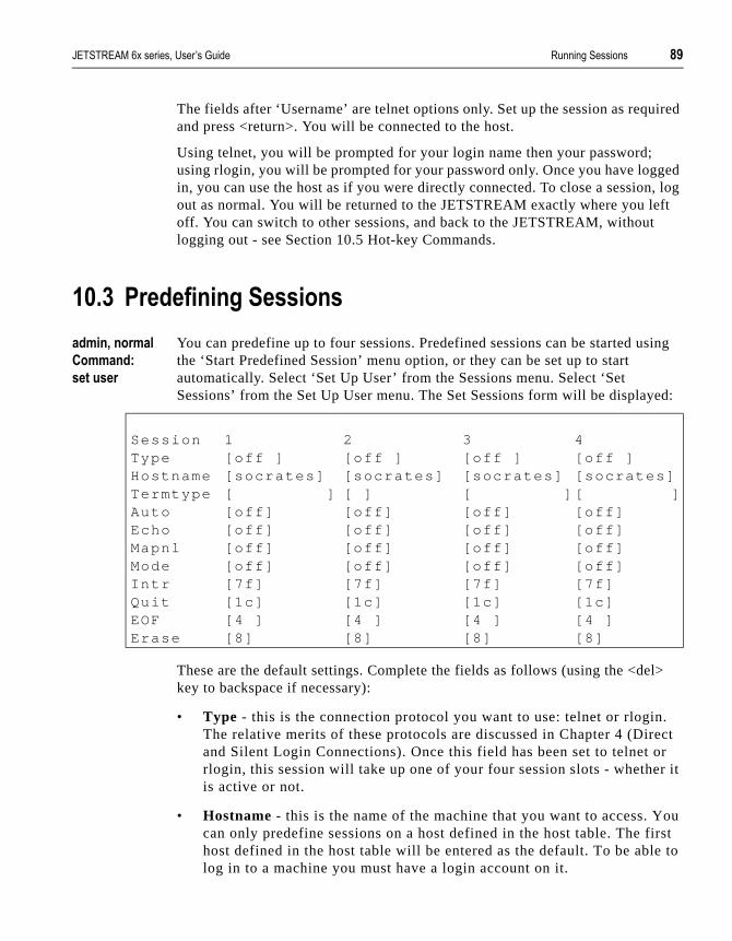
������������� �������� �������� ������,��������� 24
uired
ed , log
ft
sing
ed:
l>
. ct r
r it
ou rst e to
The fields after ‘Username’ are telnet options only. Set up the session as reqand press <return>. You will be connected to the host.
Using telnet, you will be prompted for your login name then your password; using rlogin, you will be prompted for your password only. Once you have loggin, you can use the host as if you were directly connected. To close a sessionout as normal. You will be returned to the JETSTREAM exactly where you leoff. You can switch to other sessions, and back to the JETSTREAM, without logging out - see Section 10.5 Hot-key Commands.
$)%+ � �����!�!,�������!�
����!;�!� ���
����!���
�������
You can predefine up to four sessions. Predefined sessions can be started uthe ‘Start Predefined Session’ menu option, or they can be set up to start automatically. Select ‘Set Up User’ from the Sessions menu. Select ‘Set Sessions’ from the Set Up User menu. The Set Sessions form will be display
These are the default settings. Complete the fields as follows (using the <dekey to backspace if necessary):
• Type - this is the connection protocol you want to use: telnet or rloginThe relative merits of these protocols are discussed in Chapter 4 (Direand Silent Login Connections). Once this field has been set to telnet orlogin, this session will take up one of your four session slots - whetheis active or not.
• Hostname - this is the name of the machine that you want to access. Ycan only predefine sessions on a host defined in the host table. The fihost defined in the host table will be entered as the default. To be abllog in to a machine you must have a login account on it.
Session 1 2 3 4Type [of f ] [o f f ] [o f f ] [o f f ]Hostname [socrates] [socrates] [socrates] [socrates]Termtype [ ] [ ] [ ] [ ]Auto [of f ] [of f ] [o f f ] [o f f ]Echo [of f ] [of f ] [o f f ] [o f f ]Mapnl [of f ] [of f ] [o f f ] [o f f ]Mode [of f ] [of f ] [o f f ] [o f f ]In t r [7f ] [7f ] [7f ] [7f ]Qui t [1c] [1c] [1c] [1c]EOF [4 ] [4 ] [4 ] [4 ]Erase [8] [8] [8] [8]

4) ������,��������� ������������� �������� ��������
the er.
’,
ill
n’
you
ly.
cted.
M
• Termtype - the terminal type you enter here will be passed to the hostyou are trying to log into. The termtype must be a name recognised byhost. Your system administrator should be able to tell you what to ent
• Auto - if this field is set to ‘off’, the session must be started using the ‘Start Predefined Sessions’ menu option. If the ‘Auto’ field is set to ‘onthe session will start up automatically when the user logs in to the JETSTREAM. If more than one session is set up like this, session 1 wbe displayed first.
The fields after ‘Auto’ are telnet options only.
$)%. ��� ��!,���� �����!���������!
������� �
����!������ �
Use this option to start a predefined session. Select ‘Start Predefined Sessiofrom the Sessions menu. Your predefined sessions will be listed:
Select the session that you want to start. You will be connected to the host. Ifare using telnet, you will be prompted for your login name and then your password. If you are using rlogin, you will be prompted for your password onIf you use rlogin, and your JETSTREAM login name has been entered in the‘rhost’ file of the target login directory, you will be logged straight in.
Once you have logged in, you can use the host as if you were directly conne
To close a session, log out as normal. You will be returned to the JETSTREAexactly where you left off. You can switch to other sessions, and between sessions and the JETSTREAM, without logging out (see the section “Hot-keyCommands”).
Predef ined Sessionstelnet socratestelnet p lato

������������� �������� �������� ������,��������� 4$
s, and and
at will
$)%/ 8��0#��� ����!��
������� � The commands described in Table 4 can be used to switch between sessionto switch between sessions and Full Screen/Command Line mode. The comm^a means hold down the <control>and <a> keys together. This is the screen switch character (or ‘hot-key’).
NOTE: You can change the screen switch character (^a) if it clashes with a command used by an application you are running in one of your sessions. See Section 9.6 Changing your User Environment.
Table 4 Hot-Key Commands for Session Controls
$)%/%$ 9�������,��
You can run four sessions simultaneously. Running the menu system or Command Line counts as a fifth session. If your terminal supports five videopages or more, each session can use a different page. The result of this is thwhen you switch between sessions their appearance will be maintained - theyretain their context.
Function Hot-key
Description
Switch Sessions ^a n To switch from one session to another, press ^a and then the required session number. For example, ^a 2 would switch you to session 2. You can also use these commands from the JETSTREAM to resume sessions. Pressing ^a 0 will return you to the JETSTREAM.
Display Next Session
^a n Use this command to display the next session. The current session will remain active. If you use this command from the JETSTREAM, the lowest numbered active session will be displayed.
Display Previous Session
^a p Use this command to display the previous session. The current session will remain active. If you use this command from the JETSTREAM, the highest numbered active session will be displayed.
Switch to JETSTREAM
^a m To exit a session and return to the JETSTREAM, use this command. You will be returned to where you left off. The session will be left running
Redraw Screen ^r When you switch from a session back to Full Screen Mode, the screen may not be redrawn correctly. If this happens, use this command to redraw it properly.
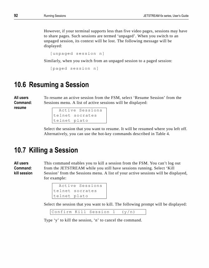
4* ������,��������� ������������� �������� ��������
have
e
off.
yed,
d:
However, if your terminal supports less than five video pages, sessions may to share pages. Such sessions are termed ‘unpaged’. When you switch to anunpaged session, its context will be lost. The following message will be displayed:
[unpaged session n]
Similarly, when you switch from an unpaged session to a paged session:
[paged session n]
$)% ������!,���������!
������� �
����!���
�����
To resume an active session from the FSM, select ‘Resume Session’ from thSessions menu. A list of active sessions will be displayed:
Select the session that you want to resume. It will be resumed where you leftAlternatively, you can use the hot-key commands described in Table 4.
$)%1 A����!,���������!
������� �
����!���
#����������!
This command enables you to kill a session from the FSM. You can’t log out from the JETSTREAM while you still have sessions running. Select ‘Kill Session’ from the Sessions menu. A list of your active sessions will be displafor example:
Select the session that you want to kill. The following prompt will be displaye
Type ‘y’ to kill the session, ‘n’ to cancel the command.
Act ive Sessionste lnet socrateste lnet plato
Act ive Sessionste lnet socrateste lnet plato
Conf i rm Ki l l Session 1 (y /n)

������������� �������� �������� �����G1��������� 4+
s
� � � - � � � # #
���� 6(������!��
$$%$ (!� �������!
This chapter contains a full description of each CLI command. The commandare described in alphabetical order and each section includes the user level required to use the command. Most but not all CLI commands have menu equivalents. Table 5 plots the menu options against their equivalent CLI commands.
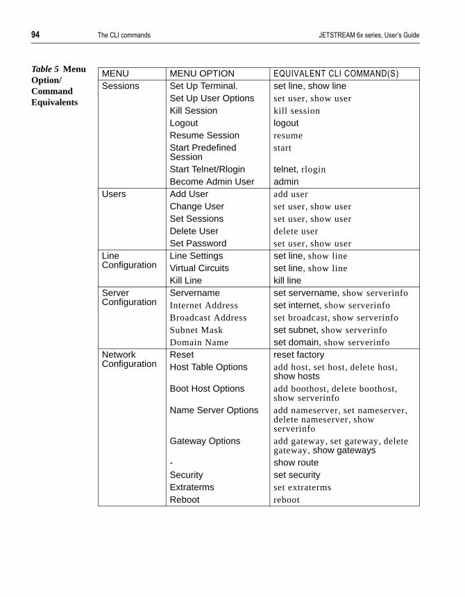
4. �����G1��������� ������������� �������� ��������
Table 5 Menu Option/Command Equivalents
MENU MENU OPTION �!�12�G�3���G1��C���39'�(
Sessions Set Up Terminal. set line, show lineSet Up User Options set user, show userKill Session kill sessionLogout logoutResume Session resumeStart Predefined Session
start
Start Telnet/Rlogin telnet, rloginBecome Admin User admin
Users Add User add userChange User set user, show userSet Sessions set user, show userDelete User delete userSet Password set user, show user
Line Configuration
Line Settings set line, show lineVirtual Circuits set line, show lineKill Line kill line
Server Configuration
Servername set servername, show serverinfoInternet Address set internet, show serverinfoBroadcast Address set broadcast, show serverinfoSubnet Mask set subnet, show serverinfoDomain Name set domain, show serverinfo
Network Configuration
Reset reset factoryHost Table Options add host, set host, delete host,
show hostsBoot Host Options add boothost, delete boothost,
show serverinfoName Server Options add nameserver, set nameserver,
delete nameserver, show serverinfo
Gateway Options add gateway, set gateway, delete gateway, show gateways
- show routeSecurity set securityExtraterms set extratermsReboot reboot

������������� �������� �������� �����G1��������� 4/
ing
. ble.
$$%* ������������
����! This command enables you to set up a boot host and boot file for net rebootthe JETSTREAM and/or downloading additional terminal definitions. Both of these features are explained in Chapter 8 (System Administration). You can define up to two boot hosts.
��!��
add boothost hostname f i lename
Where:
��!���B��>���!�
Network Configuration - Boot Hosts - Add Boot Host
��������
delete boothost, reboot, set extraterms, set netboot, show serverinfo
$$%+ ���������!���
����! This command is only available on the SNMP version of the JETSTREAM. Itenables you to define up to four SNMP communities.
Syntax
add communi ty communi ty_name inetaddressnone | readonly | readwri te
hostname is the name of the host that you want to define as a boot hostYou can only define a host that has been added to the host ta
filename is the full pathname of the bootfile (60 characters maximum).

4 �����G1��������� ������������� �������� ��������
add host
.
Where:
��������
add trap, delete community, set contact, set location, show serverinfo
$$%. ����,���3��
����! This command enables you to define the gateways in your network. You canup to eight gateways and these must be hosts that have been defined in the table.
��!��
add gateway hostname type [ inetaddress] [s tat ic ]
Where:
community_nameis an arbitrary name assigned to the community.
inetaddress is the internet address that identifies the host(s) in the community.
none | readonly |readwrite
defines the access permissions for the community.
hostname is the name of the host that you want to define as a gateway
type is the gateway type: default, host or network.
inetaddress if you define the type as host or network, you must define theinternet address of the target host or network.
static will configure the gateway as static.
For definitions of active and static see Section 6.10 Gateways
������������� �������� �������� �����G1��������� 41
ork. ently
��!���B��>���!�
Network Configuration - Gateway - Add Gateway
��������
delete gateway, set gateway
$$%/ ��������
����! This command enables you to add the details of the other hosts in your netwThese will be added to the host table. You can also add hosts accessed frequnot in your LAN.
��!��
add host hostname inetaddress
Where:
��!���B��>���!�
Network Configuration - Host Table - Add Host
��������
delete host, set host
hostname is the name of the host (14 characters maximum).
inetaddress is the internet address of the machine.

42 �����G1��������� ������������� �������� ��������
can
nd
$$% ����!����� >�
����! This command enables you to define the nameservers in your network. You define a maximum of two nameservers.
��!��
add nameserver hostname tcp_port
Where:
��!���B��>���!�
Network Configuration - Name Servers - Add Name Server
��������
delete nameserver, set nameserver, show serverinfo
$$%1 ����� ��
����! If using the SNMP version of JETSTREAM software, you can use this commato define communities which will receive trap messages generated by the JETSTREAM. Note that the JETSTREAM does not generate any enterprise-specific traps. Up to four trap comunities may be defined.
��!��
add t rap t rap_name inetaddress
hostname is the name of the nameserver.
tcp_port is the TCP port running the nameservice (this defaults to 53).
������������� �������� �������� �����G1��������� 44
r’s
Where:
��������
add community, delete trap, set contact, set location, show serverinfo
$$%2 �������
����! This command enables you to add a new user to the system. You will be prompted to enter a password (maximum 8 chars). You must also set the uselevel using the set user command.
��!��
add user username
Where username is the required login name (8 chars maximum).
��!���B��>���!�
Users - Add User
��������
delete user, set user, show user
trap_name is an arbitrary name assigned to the community.
inetaddress is the internet address that identifies the host(s) in the community.

$)) �����G1��������� ������������� �������� ��������
ut
d with
$$%4 ����!
!� ��� If you are a normal user, this command enables you to enter Admin mode. Bonly if you know the admin password. This will give you full access to the JETSTREAM commands. The JETSTREAM prompt will change to a hash (MTS#) to indicate that you are in admin mode. You must log out and back inagain to revert to your original mode.
��!��
admin
��!���B��>���!�
Sessions - Become Admin User
$$%$) ���������������
����! This command enables you to delete a boot host. The host will not be deletefrom the host table. If you have defined the same host as boot host 1 and 2 (different boot files), you must specify the name of the boot host and the full pathname of the boot file.
��!��
delete boothost hostname:f i lename
e.g . delete boothost socrates: /etc/mts/mtsprom
��!���B��>���!�
Network Configuration - Boot Hosts - Delete Boot Host
������������� �������� �������� �����G1��������� $)$
dd
an
he
an
��������
add boothost, set boothost
$$%$$ ������������!���
����! This command enables you to delete SNMP communities defined using the acommunity command.
��!��
delete community 1 | 2 | 3 | 4
Communities are numbered according to the order they are created in. You clist them using the show serverinfo command.
��������
add community, delete trap, show serverinfo.
$$%$* �������� ��
����! This command enables you to delete SNMP trapcommunities defined using tadd trap command.
��!��
delete t rap 1 | 2 | 3 | 4
Communities are numbered according to the order they are created in. You clist them using the show serverinfo command.
��������
add trap, delete community, show serverinfo.

$)* �����G1��������� ������������� �������� ��������
from
way, ot
r host er then
$$%$+ �������,���3��
����! This command enables you to delete a gateway. The host will not be deleted the host table.
��!��
delete gateway hostname
��!���B��>���!�
Network Configuration - Gateways
��������
add gateway, set gateway
$$%$. �����������
����! This command enables you to delete a host from the host table. If the host isreferenced by any predefined telnet or rlogin session, or is defined as a gatenameserver or boot host, the message <in use> will be displayed and it will nbe deleted.
��!��
delete host hostname
If you see a message saying your host is in use, you may have configured youas a boothost or as a nameserver. Delete your host as a boothost or nameservretry the delete host command.

������������� �������� �������� �����G1��������� $)+
eted
dmin
��!���B��>���!�
Network Configuration - Host Table
��������
add host, set host
$$%$/ �������!����� >�
����! This command enables you to delete a name server. The host will not be delfrom the host table.
��!��
delete nameserver hostname
��!���B��>���!�
Network Configuration - Name Servers
��������
add nameserver, set nameserver
$$%$ ����������
����! This command enables you to delete a user. You cannot delete the default auser, users that are logged in or users whose line is dedicated to them.
��!��
delete user username
$). �����G1��������� ������������� �������� ��������
est
ine:
��!���B��>���!�
Users - delete user
��������
add user, set user, show user
$$%$1 ����
����! This command tells you how much free memory currently exists and the largavailable fragment.
��!��
heap
$$%$2 ����
������� � The help command displays a brief description of how to use the Command L
��!��
help
$$%$4 #������!�
����! This command can be used to kill the processes on a line.
Type ? at any t ime to l is t possib le opt ions (e.g. set user?)
������������� �������� �������� �����G1��������� $)/
��!��
ki l l l ine n
Where n is the line that you want to kill.
��!���B��>���!�
Line Configuration - Kill Line
��������
kill session, restart, resume, set line, show line
$$%*) #����������!
������� � This command enables you to kill a session.
��!��
ki l l session n
Where n is the session that you want to kill. To see how your sessions are numbered, use the show sessions command.
��!���B��>���!�
Sessions - Kill Session
��������
kill line, logout, resume, show sessions
$) �����G1��������� ������������� �������� ��������
if
$$%*$ ��,���
������� � This command logs you off the JETSTREAM. You won’t be allowed to log outyou still have sessions running.
��!��
logout
��!���B��>���!�
Sessions - Logout
��������
kill line, kill session
$$%** ��!,
������� � If you are having trouble accessing a host, try the ping command. This tries to elicit a response from the specified host. If successful, a report similar to thefollowing will be generated:

������������� �������� �������� �����G1��������� $)1
:
You can interrupt the process by pressing any key.
If the hostname cannot be resolved, the following message will be displayed
If the host has been resolved, but the network it is on is unreachable, the following output will be generated:
If the host has been resolved, but it isn’t answering, the following will be displayed:
��!��
ping hostname/inetaddress [packet_size] [packets_sent ]
# ping socrates
PING socrates (192.101.34.1) : 100 data bytes108 bytes from 192.101.34.1: icmp.seq=0. t ime=15. ms108 bytes from 192.101.34.1: icmp.seq=1. t ime=12. ms108 bytes from 192.101.34.1: icmp.seq=2. t ime=12. ms108 bytes from 192.101.34.1: icmp.seq=3. t ime=12. ms108 bytes from 192.101.34.1: icmp.seq=4. t ime=12. ms108 bytes from 192.101.34.1: icmp.seq=5. t ime=12. ms108 bytes from 192.101.34.1: icmp.seq=6. t ime=12. ms108 bytes from 192.101.34.1: icmp.seq=7. t ime=12. ms108 bytes from 192.101.34.1: icmp.seq=8. t ime=12. ms108 bytes from 192.101.34.1: icmp.seq=9. t ime=12. ms
- - - socrates PING stat is t ics - - -10 packets t ransmit ted, 10 packets received, 0% packet loss round-t r ip (ms) min/avg/max = 12/12/15
Ping: hostname: Host not found
ping hostname / inetaddress 100 data bytes
ping: t_rcvudata: ENETUNREACH - Network isunreachable
ping hostname / inetaddress 100 data bytes
10 packets t ransmit ted, 0 packets received, 100% packet loss.

$)2 �����G1��������� ������������� �������� ��������
s
pt host nd,
e
Where:
$$%*+ ������
����! This command will reboot the JETSTREAM. You will be asked to confirm thereboot with the following prompt:
Conf i rm Reboot Server (y /n)
Type ‘y’ to reboot, ‘n’ to cancel.
By default, the JETSTREAM boots from ROM. If the net rebooting facility habeen enabled, it will try to reboot from a specified boot file. The JETSTREAMwill continue trying to access the boot file until successful or until you interruthe process by pressing a key on the console. If no boot file is found on boot 1, the process will be repeated on boot host 2 if defined. If no boot file is fouJETSTREAM will boot from ROM.
Rebooting does not reset the JETSTREAM to factory default settings.
The rebooting process can also be used to download terminal definitions (seSection 8.4 Downloading Terminal Definitions).
��!��
reboot
��!���B��>���!�
Network Configuration - Reboot - Reboot Server
��������
set extraterms, set netboot, show serverinfo
hostname/inetaddress
is the hostname or internet address of the machine that youwant to ping.
packet_size is the size of packet sent (default = 100 bytes).
packets_sent is the number of packets sent (default = 10).

������������� �������� �������� �����G1��������� $)4
.
$$%*. ���������� �
����! This command will reset the JETSTREAM to its default values.
��!��
reset factory
��!���B��>���!�
Network Configuration - Reset
��������
reboot
$$%*/ �������!�
����! This command will reset the specified line(s) to the default line configuration
��!��
reset l ine . / n /*
Where:
��!���B��>���!�
Line Configuration - Line Settings/Virtual Circuits - Quit form
. specifies the current line.
n is a specific line number.
* specifies all lines.

$$) �����G1��������� ������������� �������� ��������
is
t.
e, ntil and.
��������
reboot
$$%* ��������
����! This command will reset the specified user(s) to the default user settings. Thsets the user level to ‘normal’ and the screen switch character to ‘1’. Any predefined sessions are switched off. The default admin user will not be rese
��!��
reset user . / * / username
Where:
��������
reboot
$$%*1 ���� �
����! When there is insufficient free memory to start a login or virtual circuit on a linthat line will appear dead and you will be unable to restart it. You must wait usufficient memory is available and then restart all such lines using this commYou can enter the command on any active line.
��!��
restar t
. specifies the current user.
username is the name of a specific user.
* specifies all users.

������������� �������� �������� �����G1��������� $$$
boot
��������
heap
$$%*2 ���� �
����! This command enables you to restore the configuration information saved to host 1.
��!��
restore
You will be asked to confirm the restore configuration.
��������
save
$$%*4 �����
������� � The resume command enables you to resume any session that you have leftrunning. You will be returned to where you left off.
��!��
resume n
Where n is the session you want to resume.
��!���B��>���!�
Sessions - Resume Session

$$* �����G1��������� ������������� �������� ��������
ol.
ed ).
d
s
��������
kill session, start
$$%+) ��,�!
����!�!� ��� This command will establish a connection with a host using the rlogin protocRlogin passes your login name to the host, so you are prompted for your password only. If your JETSTREAM login name exists in the ‘rhost’ file of thetarget login directory, you won’t be prompted for a password. You will be loggstraight in. Rlogin and telnet are compared in Chapter 10 (Running Sessions
��!��
r login hostname/inetaddress [ termtype termtype ] [user username ]
Where:
��!���B��>���!�
Sessions - Start telnet/rlogin
��������
kill session, resume, show line, start, telnet
hostname/inetaddress
is the hostname or internet address of the machine you wantto log into.
termtype is your terminal type. By default a dumb terminal type is passeto the host. When connecting to a UNIX host, you must definethe termtype in accordance with its UNIX TERM variable.
username is your login name on the target host if different to your JETSTREAM login. You can also use this argument to log in asomeone else.
������������� �������� �������� �����G1��������� $$+
nit
en
sfer
de
$$%+$ ��>�
����! This command enables you to save the configuration of your JETSTREAM uto a remote host. The configuration can subsequently be reloaded using the restore command. The following information will be saved:
User Profiles
Port Configuration
Host Table
Gateways
Fixed data and JETSTREAM information will not be saved. Data will be writtto the file /etc/mts/config/servername on boot host 1. Most UNIX versions of TFTP require this file to exist and to have global write permission before trancan take place.
��!��
save
You will be asked to confirm the restore configuration.
��������
restore
$$%+* �� ��!
������� � This command will change you from Command Line mode to Full Screen mo(on supported terminal types only).
��!��
screen

$$. �����G1��������� ������������� �������� ��������
ce ess
$$%++ ����� �������
����! • This command enables you to set or change your broadcast address. Onyou have entered an IP address and subnet mask, the broadcast addrwill default to the IP address with the host part(s) set to 255.
. You must reboot after changing the broadcast address.
��!��
set broadcast broadcast_address
��!���B��>���!�
Server Configuration
��������
reboot, show serverinfo
$$%+. ������!����
����! If using the SNMP version of JETSTREAM, this command enables you to configure the SNMP sysContact object.
��!��
set contact contact_name
Where contact_name is a string which cannot contain spaces (e.g. john.smith,john_smith or johnsmith)
��������
set location

������������� �������� �������� �����G1��������� $$/
boot
ns
$$%+/ ���������!
����! This command enables you to set or change your domain name. You must rethe JETSTREAM afterwards.
��!��
set domain domain_name
��!���B��>���!�
Server Configuration
��������
reboot, show serverinfo
$$%+ ������ ��� ��
����! The Extraterms feature enables you to download additional terminal definitiofrom a remote host at boot time (see Section 8.4 Downloading Terminal Definitions). The set extraterms command allows you to enable/ disable this feature.
��!��
set extraterms on/of f
��!���B��>���!�
Network Configuration - Extraterms

$$ �����G1��������� ������������� �������� ��������
osts
.
��������
add boothost, set netboot
$$%+1 ����,���3��
����! This command enables you to redefine a gateway.
��!��
set gateway hostname type [ inetaddress] [s tat ic ]
Where:
��!���B��>���!�
Network Configuration - Gateway - Change Gateway
��������
add gateway, delete gateway
$$%+2 ��������
����! Use this command if you need to change the internet address of one of the hin your host table.
hostname is the name of the gateway.
type is ‘default’, ‘host’ or ‘network’. If host or network.
inetaddress is the internet address of the target host or network.
static will configure the gateway as static.
For definitions of active and static see Section 6.10 Gateways

������������� �������� �������� �����G1��������� $$1
��!��
set host hostname inetaddress
��!���B��>���!�
Network Configuration - Host Table - Change Host
��������
add host, delete host, show hosts
$$%+4 �����!�� !��
����! This command enables you to set or change the internet address of the JETSTREAM. You must reboot the JETSTREAM afterwards.
��!��
set in ternet inetaddress
��!���B��>���!�
Server Configuration
��������
reboot, show serverinfo

$$2 �����G1��������� ������������� �������� ��������
f any nges her
s
u
e
$$%.) ������!�
����!�!� ��� Use this command to configure lines. An admin user can change the setup oline; a normal user can change their own line only. On login connections, chato the terminal type or number of video pages will take effect immediately. Otchanges will take effect when someone next logs in on the line.
��!��
set l ine l ine_number [speed speed ] [par i ty par i ty ] [stop stop_bits ] [data data_bi ts ] [ f low f low_contro l ] [pages no_pages ] [ termtype termtype ] [modem on/of f ] [user username ] [nouser] [ type l ine_type raw/te lnet hostname mts_port host_port ]
Where:
line_number may also be specified as ‘*’ for all lines or ‘.’ for the line currently being used.
pages (for normal connections) is the number of video pages the terminal supports.
user (for normal connections) can be used to dedicate the line to aspecific user. Only this user will be able to log in on this line and they won’t need to enter their login name - just their password.
nouser (for normal connections) nullifies the user argument; it enableany user to log in on this line.
line_type is the type of connection required: normal, direct, silent, reverse, printer or bimodem.
raw/telnet (for direct, silent or reverse connections) specifies whether yowant the connection to be ‘raw’ or ‘telnet’.
hostname (for direct, silent and bimodem connections) is the name of thtarget host.

������������� �������� �������� �����G1��������� $$4
rt n.
The other arguments are standard line setting arguments. Any number or combination of the arguments can be used.
Examples:
set l ine 6 type s i lent te lnet p lato
set l ine 3 type reverse raw 1000
set l ine 9 speed 38400 modem on type bimodem homer 1000 900
��!���B��>���!�
Line Configuration - Line Settings/Virtual Circuits
��������
show line
$$%.$ �����������!
����! If using the SNMP version of JETSTREAM, this command enables you to configure the SNMP sysLocation object.
��!��
set locat ion locat ion
mts_port (for reverse raw and bimodem connections) is the TCP port number assigned to the JETSTREAM port. TCP/IP hosts will use this TCP port to establish a connection with the JETSTREAM.
host_port (for direct raw, silent raw and bidir connections) is the TCP poassigned on the target host to listen for the incoming connectio

$*) �����G1��������� ������������� �������� ��������
e on
ou
n)
��������
set contact
$$%.* ����!����� >�
����! Use this command to re-define the TCP port number running the nameservica nameserver.
��!��
set nameserver hostname tcp_port
��!���B��>���!�
Network Configuration - Name Servers - Change Name Server
��������
add nameserver, delete nameserver
$$%.+ ����!������
����! If you want to reboot the JETSTREAM from ROM, set netboot must be set to ‘off ’. This is the default setting. If you want to net reboot the JETSTREAM, set netboot must be set to ‘on’. This command will not reboot the JETSTREAM, ymust use the reboot command for that.
Net rebooting is described in more detail in Chapter 8 (System Administratiounder the heading Upgrading System Software.
��!��
set netboot on/of f

������������� �������� �������� �����G1��������� $*$
ter y
n its rs.
��!���B��>���!�
Network Configuration - Reboot - Set Net Reboot
��������
add boothost, reboot, show serverinfo
$$%.. �������� ���
����! By enabling this feature, you restrict incoming connections (reverse and prinline types and remote configuration) to the hosts defined in the host table. Bdefault, this feature is disabled (off).
��!��
set secur i ty on/of f
��!���B��>���!�
Network Configuration - Security
$$%./ ������ >� !���
����! This command enables you to set or change the name of the JETSTREAM (ifunction as a Terminal Server). The name can be a maximum of 14 characteYou must reboot the JETSTREAM afterwards.
��!��
set servername servername
$** �����G1��������� ������������� �������� ��������
ust
ned
��!���B��>���!�
Server Configuration
��������
reboot, show serverinfo
$$%. �������!��
����! Use this command to set or change the subnet mask of your network. For a definition of subnet mask, see Section 3.3 JETSTREAM Configuration. You mreboot the JETSTREAM afterwards.
��!��
set subnet subnet_mask
��!���B��>���!�
Server Configuration
��������
reboot, show serverinfo
$$%.1 �������
����!�!� ��� This command enables you to set or modify a user’s setup, including predefisessions. An admin user can change any user setup; a normal user can onlychange their own setup.
������������� �������� �������� �����G1��������� $*+
nd to
r user
ts
��!��
set user username /. [password] [ level user_level ] [switch screen_switch_char ] [session n . . . ]
Where:
. . . session n /* type te lnet / r login host hostname [ termtype termtype ] [auto on/of f ] [echo on/of f ] [mapnl on/of f ] [mode on/of f ] [ in t r < hex >] [qui t < hex >] [eof < hex >] [erase < hex >]
You can use any number or combination of the arguments. Use the ? commalist the options for each one. An example is given below:
This command has set up four predefined telnet sessions on host socrates fo‘john’.
��!���B��>���!�
Users - Change User/Set Password
password if you include this argument you will prompted to enter a new password.
user_level is ‘admin’, ‘normal’ or ‘restricted’.
screen_switch_char
is the hex value of the ‘hot-key’ used for switching sessions.The default is 1 (^a). See the ascii code chart in Section F.2 ASCII to Decimal and Hex Code Chart.
session use this argument to predefine sessions for the user. You canpredefine one specified session (n), or all sessions (*). It takes the following arguments:
You must specify the type and hostname. The other argumenare optional. The arguments after auto are telnet options.
set user john level normal swi tch 02 session* typete lnet host socrates termtype wyse60

$*. �����G1��������� ������������� �������� ��������
��������
add user, delete user
$$%.2 ���3�,���3���
����!�!� ��� Use this command to list the gateways you have defined. The list will be displayed in the following format:
��!��
show gateways
��!���B��>���!�
Network Configuration - Gateways - Change Gateway
��������
add gateway, delete gateway, set gateway
$$%.4 ���3������
����!�!� ��� Use this command to list the contents of the host table:
Hostname Type Internet Address Stat icsocrates defaul t Noplato host 192.65.144.4 Yes
Hostname Internet Addresssocrates 192.65.144.89plato 192.65.144.4homer 192.65.144.76ar istot le 192.65.144.11

������������� �������� �������� �����G1��������� $*/
��!��
show hosts
��!���B��>���!�
Network Configuration - Host Table - Change Host
��������
add host, delete host, set host
$$%/) ���3���!�
����!�!� ��� This command can be used to display the configuration of a single line or alllines. Admin users can show all lines, normal users can only display the configuration of their own line. If you specify all lines, the display will look likethis:
If you specify a particular line, the following information will be displayed:
line settings, line type (including hostname and tcp port where appropriate), current user (normal line type only) and active sessions.
Below is an example:
Line Speed Usage1 57600 si l te l p lato 23 v ir tual c i rcui t2 57600 si l te l p lato 23 v ir tual c i rcui t3 57600 si l te l p lato 23 v ir tual c i rcui t4 57600 si l te l p lato 23 v ir tual c i rcui t5 57600 si l haw plato 24 v ir tual c i rcui t6 57600 reverse 9007 57600 pr inter8 38400 Console admin telnet:16 38400 alan r login r login
MTS # sh l i 6Line Speed Term Modem Flow Bits Pari ty Stop Pages Type ho/
mts
$* �����G1��������� ������������� �������� ��������
is a
rk.
In this example, in the ho/mts field, the --/900 are tcp port numbers. As this reverse raw connection, the tcp port (900) is allocated on the JETSTREAM (MTS); no tcp port is allocated on the host.
��!��
show l ine . / n /*
Where:
��!���B��>���!�
Line Configuration - Virtual Circuits/Line Settings
��������
set line, show user
$$%/$ ���3� ����
The output of this command will give you a better understanding of your netwoBelow is an example:
6 9600 wyse60
of f sof t 8 none 1 3 reverse
-- /900
. specifies the current line.
n is a specific line number.
* specifies all lines
Dest inat ion Gateway Flags Refs Use Inter- face
192.101.35.192 192.101.35.217 U 1 1 1e00.0.0.0 192.101.35.217 UG 0 0 1e0
������������� �������� �������� �����G1��������� $*1
on more
1).
��!��
show route
��!���B��>���!�
there is no menu equivalent
Note the output to this command is synonymous with that from the ‘netstat -r’ commandmost Unix systems. See the manpages (type “man netstat” on your Unix system forinformation.
$$%/* ���3��� >� �!��
����! This command displays the configuration of the JETSTREAM, for example:
The SNMP information is only displayed if you are running JETSTREAM software which includes SNMP support (referred to as models 6001 and 650
Servername mtsInternet address 192.65.144.91Subnet Mask 255.255.255.0Broadcast address 192.65.144.255Domain Name special ix.co.uk
Name Servers plato (53)Boot Hosts plato: /etc/mts/mtspromNet Reboot onSecur i ty of fExtraterms on
SNMP:Contact johnsmithLocat ion x235Communit ies: 1. homer 192.65.144.78 read/wri te
2. local 192.65.144.2.55 read onlyTraps: 1. local 192.65.144.255

$*2 �����G1��������� ������������� �������� ��������
s),
��!��
show serverinfo
��!���B��>���!�
Server Configuration
��������
add boothost, add community, add trap, set broadcast, set contact, set domain, set extraterms, set internet, set location, set netboot, set security, set servername, set subnet
$$%/+ ���3�������!�
����!�!� ��� This command lists your active sessions (including active predefined sessionfor example:
1 telnet socrates
��!��
show sessions
��!���B��>���!�
User - Set Up User - Set Sessions
��������
resume
$$%/. ���3����

������������� �������� �������� �����G1��������� $*4
see view
ant m by for
d in
����!�!� ��� Use this command to display a user’s setup, including predefined sessions (below). The admin user can show details of any user, a normal user can only their own details.
��!��
show user . / username
Where:
��!���B��>���!�
Admin user: Users - Change User/Set Sessions.Normal user: Sessions - Set Up User/Set Sessions
��������
set user
$$%// ��� �
������� � Use this command to start a predefined session. This is a particularly importcommand for restricted users who can only start sessions predefined for thesystem administrator. If you are using telnet, the target host will prompt you your login name. If you are using rlogin, the host will prompt you for your password. If you are using rlogin and your JETSTREAM login name is enterethe ‘rhost’ file of the target login directory, you will be logged straight in.
# show userUsername Language Screen Switch Char Typeadmin engl ish 01 admin
Type Hostname Auto Echo Mapnl Mode Intr Quit EOF Erase Term1 r login socrates off of f of f of f 7f 1c 04 08 ansi2 r login homer off of f of f of f 7f 1c 04 08 ansi
. specifies the current user.
username is the name of a specific user.

$+) �����G1��������� ������������� �������� ��������
ing are
g
r u
��!��
start n
Where n is the predefined session that you want to start.
��!���B��>���!�
Sessions - Start Predefined Session
��������
resume, start telnet/rlogin
$$%/ ���!��
����!�!� ��� This command will establish a connection with another host on the network usthe telnet protocol. You must specify the target host but the other argumentsoptional. When the connection is made you will be prompted for your login name.
��!��
te lnet hostname/inetaddress [ termtype termtype ] [echo on/of f ] [mapnl on/of f ] [mode on/of f ] [ in tr < hex >] [qui t < hex >] [eof <hex>] [erase <hex >]
Where:
hostname/inetaddress
is the name or internet address of the machine you want to lointo
termtype is your terminal type. This argument enables you to pass youterminal type to the host. When connecting to a UNIX host, yomust define the termtype in accordance with its UNIX TERM variable.

������������� �������� �������� �����G1��������� $+$
g.
��!���B��>���!�
User - Start telnet/rlogin
��������
kill session, resume, rlogin, show session, start
$$%/1 >� ���!
����!�!� ��� This command tells you what version of software your JETSTREAM is runnin
��!��
version
��!���B��>���!�
Version of software is displayed at the top of the screen.

$+* �����G1��������� ������������� �������� ��������

������������� �������� �������� ��������*��-���%�������� $+$
d
� - - � � � � � �
����!�����������������!�
�%$ (!� �������!
This appendix contains the following technical specifications:
• in Section A.2 6000 and 6001 models (desk/wall-mounted versions)
• in Section A.3 Modular Terminal Adaptor (MTA)in Section A.4 6500 an6501 models (rack-mounted versions).
It also contains:
• Section A.5 Summary of Line types

$+* ��������*��-���%�������� ������������� �������� ��������
�%* )))��!��))$�������
�!>� �!��!���
������������!
��3�
The 6000 and 6001 models have an external power supply.
��� �� ������
Ambient Temperature Operating 0°C - +50°CStorage -40°C - +85°C
Relative Humidity Operating 5% - 95% non-condensingStorage 0% - 100% non-condensing
5% - 95% condensingEmissions Conforms to EN55022 Class A, FCC Class AImmunity Conforms to EN50082-1
Dimensions Length: 257mm (10.12 in)Width: 200mm (7.78 in)Height: 32mm (1.26 in)
Mounting wall or desk
Power Supply Rating 44WPower consumption 10W
Device 80386 25MHz

������������� �������� �������� ��������*��-���%�������� $++
�%+ ������ ��� ��!��������� �<���=
����� �
�!>� �!��!���
������������!
��3� The MTA takes power from the JETSTREAM to which it is attached.
-��&(&� Do not connect or disconnect the MTA to/from the JETSTREAM while the power is on. You will damage the units, may cause a fire and possibly injure yourself.
JETSTREAM model numbers to which an MTA can attach 6000 and 6001
Number of MTAs which you can attach to a JETSTREAM one only
Ambient Temperature Operating 0°C - +50°CStorage -40°C - +85°C
Relative Humidity Operating 5% - 95% non-condensingStorage 0% - 100% non-condensing
5% - 95% condensingEmissions Conforms to EN55022 Class A, FCC Class AImmunity Conforms to EN50082-1
Dimensions Length: 257mm (10.12 in)Width: 95 mm (3.7 in)Height: 32 mm (1.26 in)
Mounting via the JETSTREAM to which it is attached (and to the wall, if wall-mounted).

$+. ��������*��-���%�������� ������������� �������� ��������
�%. /))��!��/)$�������
�!>� �!��!���
������������!
��3�
The JETSTREAM 6500 connects directly to mains power. The internal power supply converts mains voltage to the required operating voltage.
��� �� ������
Ambient Temperature Operating 0°C - +50°CStorage -40°C - +85°C
Relative Humidity Operating 5% - 95% non-condensingStorage 0% - 100% non-condensing
5% - 95% condensingSafety of IT equipment including electrical business equipment
Conforms to EN60950and CAN/CSA C22.2 No 950-95/UL1950
Emissions Conforms to EN55022 Class A, FCC Class AImmunity Conforms to EN50082-1
Dimensions Height: 89mm (2U)Width: 483mmDepth: without handles,
with handles, 245mm285mm
Mounting standard 19 inch rack practiseWeight 3.8 kg, assembled
Input 110V - 240V, 50-60 Hz ACPower consumption 20W
Device 80386 25MHz

������������� �������� �������� ��������*��-���%�������� $+/
�%/ ����� �����6�!�������
Line Type Uses Example How to setup
Normal The default connection. You are logged into the JETSTREAM. Then, four telnet/rlogin sessions can be started to remote hosts.
For JETSTREAM configuration. Also for users customizing their own sessions.
Section 4.1 Introduction
Direct (telnet or rlogin)
To bypass the JETSTREAM and allow users to login straight into a specific host. These are non-permanent connections
Users on terminals. Section 4.4 Setting Up Direct/Silent Login Connections
Silent(telnet or rlogin)
To bypass the JETSTREAM and allow users to login straight into a specific host. These are permanent connections, therefore consume system resources
Users on terminals. Section 4.4 Setting Up Direct/Silent Login Connections
Printer Remote printing using RCP Using JETSTREAM as a printer server
Section 7.3 Remote Printing Using RCP
Silent Raw Enables external non-login devices to access TCP/IP servers via JETSTREAM. These connections are established automatically; they are suitable for computer to computer communications.
Dialin connections Section 7.5 Dialin Modem Connections

$+ ��������*��-���%�������� ������������� �������� ��������
Direct Raw Enables external non-login devices to access TCP/IP servers via JETSTREAM. These connections are established by pressing <return>.
User applications Section 7.2 Overview of Line Types
Reverse Raw
Simple pipe between a TCP/IP hostand a machine/device attached to a JETSTREAM port
Typically to access printers or dialout modems (need host-based print/modem handling software).
Section 7.4 Remote Printing Using Host-Based Print Handling Software
see also:Section 7.6 Dialout Modem Connections
Reverse Telnet
a) Enables a TCP/IP host to establish a login connection on an external machine attached to a JETSTREAM port
b) Enables a TCP/IP host to establish a login connection to the JETSTREAM
a) To access machines like protocol converters or statistical multiplexors.
b) for admin purposes.
Section 7.9 Reverse Telnet Connection
Bidir Allows a bidirectional modem connection on a JETSTREAM port
Since the modem can be used for simultaneous dialin and dialout connections, an example use would be a UUCP connection for batch file transfer and printing.
Section 7.7 bidirectional Modem Connections
Line Type Uses Example How to setup

������������� �������� �������� �� ���-���%��������H����*��,��&&&�����*���*� $+1
.
ix ent.
ons
� - - � � � � � /
�� ��������������!�C� ����!,;)))��������!��
@%$ 7>� >��3
Note. The information in this appendix concerns the 6000 and 6001 models onlyFor the 6500 and 6501 models go to Appendix C (Port Specifications &
Cabling: 6500 model only).
This appendix describes pin specifications of the various types of Specialconnectors. It also guides you in cabling your devices to Specialix equipm
The contents of this appendix is pin specifications, and example connectifor most Specialix connectors.
Pin specifications:
• RS232 DB25 Ports (Female) DCE Section B.2
• RS232 DB25 Ports (Male) DTE Section B.3
• RS232* (asterisk) DB25 Ports Section B.4
• RS232 RJ45 ports (with shielded connector) Section B.5
• Parallel DB25 Port Section B.28
• RS232 RJ45 Opto-isolated Ports Section B.29
• RS422 DB25 Ports Section B.30

$+2 �� ���-���%��������H����*��,��&&&�����*���*� ������������� �������� ��������
Connection examples:
• for Direct (1:1) connections, see mini-Table of Contents at Section B.8.1.
• for Structured Cabling Systems, see mini-Table of Contents at Section B.22.1
������������� �������� �������� �� ���-���%��������H����*��,��&&&�����*���*� $+4
such or
ur
@%* ��*+*�'@*/��� ���<������=�' �
These ports provide a full RS232 interface for serial devices. The female DB25 connectors are wired as RS232 Data Communications Equipment (DCE).
Use a straight through cable to be used when connecting to DTE devices as terminals. When connecting to other DCE devices, such as modems, acrossover cable must be used. See Section B.8.1 Example Connections fguidance.
The RS232 DB25 DCE serial pinouts are:
���*��
��0:0�9/0)�
'%���*�(�-��=����
Notes:
1. P/GND means Protective (Chassis) Ground
2. S/GND means Signal Ground
Optionally you can order these ports with surge suppression. This feature enables the ports to absorb high static discharges and surges. Contact yoSpecialix supplier for more information.
Pin Circuit Direction Function1 P/GND - Connect to case2 RXD Input Receive Data3 TXD Output Transmit Data4 RTS Input Transmit Hardware Flow Control5 CTS Output Receive Hardware Flow Control6 DSR Output Data Set Ready7 S/GND - Connect to logic 0V8 DCD Input Data Carrier Detect20 DTR Input Data Terminal Ready22 RI Input Ring Indicator

$.) �� ���-���%��������H����*��,��&&&�����*���*� ������������� �������� ��������
25
e
ur
@%+ ��*+*�'@*/��� ���<����=�'��
These ports provide a full RS232 interface for serial devices. The male DBconnectors are wired as RS232 Data Terminal Equipment (DTE).
You can use straight (pin 1 to pin 1, etc.) connections to Data Communications Equipment (DCE) such as modems. When connecting toother DTE devices, such as terminals, a crossover cable or device must bused. See Section B.8.1 Example Connections for guidance.
The RS232 DB25 DTE serial pin-outs are:
���*��?
��0:0�9/0)�
'��*�(�-��=����
Notes:
1. P/GND means Protective (Chassis) Ground
2. S/GND means Signal Ground
Optionally you can order these ports with surge suppression. This feature enables the ports to absorb high static discharges and surges. Contact yoSpecialix supplier for more information.
Pin Circuit Direction Function1 P/GND — Connect to case2 TXD Output Transmit Data3 RXD Input Receive Data4 RTS Output Receive Hardware Flow Control5 CTS Input Transmit Hardware Flow Control6 DSR Input Data Set Ready7 S/GND — Connect to logic 0V8 DCD Input Data Carrier Detect20 DTR Output Data Terminal Ready22 RI Input Ring Indicator

������������� �������� �������� �� ���-���%��������H����*��,��&&&�����*���*� $.$
he
en
see
nd
@%. ��*+*D�<���� ��#=�'@*/��� ��
On the casing of your product, DB25 ports marked with an asterisk after tletters RS232. These RS232 ports have reduced capability: they do not support the Ring Indicator (RI) or Data Terminal Ready (DTR) signals. Whcabling your devices to a RS232* port, bear in mind this limitation.
See pin-out details for DB25 connectors in Table 6 or Table 7.
The RS232 * ports are part of an option where a parallel port is provided; Figure 13. One of the ports in the group is a parallel port.
F�,� ��#: �
��0:0I�-� ��
As an option you can have order the RS232* ports with surge suppressioncapability. This feature allows the ports to absorb high static discharges asurges.
$.* �� ���-���%��������H����*��,��&&&�����*���*� ������������� �������� ��������
45
les
ur
@%/ ��*+*���./��� ���<3���������������!!���� =
The shielded RS232 RJ45 ports comply with the RS232 specification.
Note. (There is an older non-shielded version of these ports; see Section B.6 RJPorts (no shielding).
For help on cabling, see Section B.8.1 Example Connections. The exampinclude structured cabling environments.
There is additional information on structured cabling systems; see SectionB.21 Structured Cabling Systems.
The pin-outs are shown in Table 8.
���*��6
����*������7)�-��=
����
Notes:
1. P/GND means Protective (Chassis) Ground
2. S/GND means Signal Ground
Optionally you can order these ports with surge suppression. This feature enables the ports to absorb high static discharges and surges. Contact yoSpecialix supplier for more information.
Pin Circuit Direction Function1 DCD Input Data Carrier Detect2 DSR Output Data Set Ready3 DTR Input Data Terminal Ready4 S/GND — Signal Ground5 TXD Output Transmit Data6 RXD Input Receive Data7 CTS Output Clear To Send8 RTS Input Request To SendShield P/GND — Protective (Chassis) Ground

������������� �������� �������� �� ���-���%��������H����*��,��&&&�����*���*� $.+
see
The pins in the RJ45 socket are located at the top, with pin 1 on the left (Figure 14).
Viewing the RJ45 plug from above (with the clip underneath), the pins arenumbered as follows:
F�,� ��#7
��7)�����
3���� ��,����
� � � � � � � �
�����
���

$.. �� ���-���%��������H����*��,��&&&�����*���*� ������������� �������� ��������
d )).
@% ��./��� ���������������
These RJ45 ports do not have shielding around the connector.
Note: these ports are being phased out. Their replacement are the shieldeRJ45 ports; (see Section B.5 RS232 RJ45 ports (with shielded connector
The pin-outs are as follows:
���*��>
�����������
��7)�-��=�����
Notes:
1. S/GND means Signal Ground
To determine the position of pins inside the connector, see Figure 14.
Pin Circuit Direction Function1 DSR Output Data Set Ready2 DCD Input Data Carrier Detect3 RXD Input Receive Data4 CTS Output Receive Hardware Flow Control5 S/GND — Ground6 TXD Output Transmit Data7 DTR Input Data Terminal Ready8 RTS Input Receive Hardware Flow Control

������������� �������� �������� �� ���-���%��������H����*��,��&&&�����*���*� $./
ed
; en.
ot be this put. e
nect
es
the
@%1 '� ����<$�$=� �!!�����!�
This section details direct (1:1) connections (definition below). For structurcabling systems, go toSection B.21 Structured Cabling Systems.
Definition of a Direct (1:1) connection:
a single length of cable joins the Specialix device and your equipmentthere is no structured cabling system or any other connection in-betwe
Notes:
1. Some user equipment need additional signals on the connector. These may nsupported by the Specialix device or your cable. The normal way to overcomeis to loop-back - on your equipment - one of the output lines to the required inRefer to the documentation supplied with your equipment, or the supplier of thequipment, for information on which loop-backs, if any, are required.
2. Other than a specific requirement at your equipment (as in note 1), do not conunused pins on either connector.
3. On the DB25 connector, Protective Ground (P/GND) is pin 1. On the RJ45 connector, Protective Ground (P/GND) terminates on the connector and so donot have a pin number.
@%2%$� ������� �!!�����!�
In this section we show example connections between Specialix ports andfollowing devices:
Terminals
Terminals (slow speed or using software flow control)
Section B.10.1
Terminals (faster speed or using Hardware Flow Control)
Section B.11.2
Terminal Connection using the modem device, Without hardware flow control:
Section B.13.1

$. �� ���-���%��������H����*��,��&&&�����*���*� ������������� �������� ��������
Terminal Connection using the modem device, With hardware flow control:
Section B.14.2
Modems
direct (1:1) connections: Section B.16.1
PCs (DB9 connectors)
direct (1:1) connections Section B.17
Serial Printers
with software flow control Section B.19.1
with hardware flow control Section B.20.2
Terminals
������������� �������� �������� �� ���-���%��������H����*��,��&&&�����*���*� $.1
not be this t.
@%4 �� ��!���
@%$)%$� �� ��!����<���3�������� ����!,�����3� �����3���!� ��=
For a standard terminal operating at slow speeds, or using software flow control, a simple 3-pin connection can be used:
Notes:
1. Some terminals need additional signals on the connector. These signals may supported by the Specialix device, or your cable. The normal way to overcomeis to loop-back one of the output lines from the terminal into the required inpuRefer to the documentation supplied with your terminal, or the supplier of the terminal, for information on which loop-backs, if any, are required.
2. In addition to the signals shown in the examples above, you may connect Protective Ground (P/GND), at either your equipment or the Specialix device (but not both). P/GND will reduce interference in noisy environments.
Special ix device TerminalDB 25 Female (DCE) DB 25
RXD 2 <——————— 2 TXDTXD 3 ———————> 3 RXDGND 7 ———————— 7 GND
Special ix device TerminalDB 25 Male (DTE) DB 25
TXD 2 ———————> 3 TXDRXD 3 <——————— 2 RXDGND 7 ———————— 7 GND
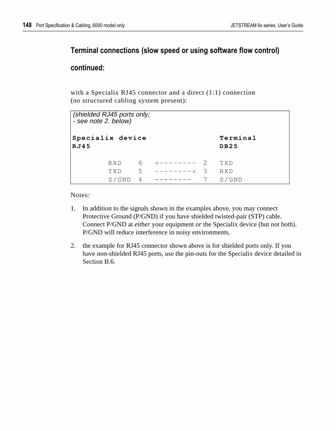
$.2 �� ���-���%��������H����*��,��&&&�����*���*� ������������� �������� ��������
ed in
�� ��!�����!!�����!��<���3�������� ����!,�����3� �����3���!� ��=
��!��!����
with a Specialix RJ45 connector and a direct (1:1) connection(no structured cabling system present):
Notes:
1. In addition to the signals shown in the examples above, you may connect Protective Ground (P/GND) if you have shielded twisted-pair (STP) cable. Connect P/GND at either your equipment or the Specialix device (but not both). P/GND will reduce interference in noisy environments.
2. the example for RJ45 connector shown above is for shielded ports only. If youhave non-shielded RJ45 ports, use the pin-outs for the Specialix device detailSection B.6.
(shielded RJ45 ports only;- see note 2. below)
Specia l ix device TerminalRJ45 DB25
RXD 6 <———————— 2 TXDTXD 5 —————--—> 3 RXDS/GND 4 ———————- 7 S/GND

������������� �������� �������� �� ���-���%��������H����*��,��&&&�����*���*� $.4
re
t
@%$$%*� �� ��!���<����� �������� ����!,�8� �3� �����3� �!� ��=
For a slow terminal operating at speeds faster than 9600 baud, or for a terminal which can’t use xon/xoff flow control, the following connections arequired:
:
Notes:
1. * asterisk denotes that you should connect these pins only if input (from the Terminal to the Specialix device) flow control is required.
2. the pins used for hardware flow control may vary from terminal to terminal, buRTS (pin 4) on the Specialix device port must be connected to the pin on the terminal which indicates that the terminal buffer is full.
3. In addition to the signals shown in the examples above, you may connect Protective Ground (P/GND), at either your equipment or the Specialix device (but not both). P/GND will reduce interference in noisy environments.
Specia l ix device TerminalDB25 Female (DCE) DB25
RXD 2 <——————— 2 TXDTXD 3 ———————> 3 RXDRTS 4 <——————— 4 or 20 RTS/
DTR*CTS 5 ———————> 5 *CTSGND 7 ——————— 7 GND
Specia l ix device TerminalDB25 Male (DTE) DB25
TXD 2 ———————> 3 RXDRXD 3 <——————— 2 TXD*RTS 4 ———————> 5 *CTSCTS 5 <——————— 4 or
20RTS/DTR
GND 7 ——————— 7 GND

$/) �� ���-���%��������H����*��,��&&&�����*���*� ������������� �������� ��������
this .
4. Some terminals need additional signals on the connector. These may not be supported by the Specialix device, or your cable. The normal way to overcomeis to loopback one of the output lines from the terminal into the required inputRefer to the documentation supplied with your terminal, or the supplier of the terminal, for information on which loop-backs, if any, are required.

������������� �������� �������� �� ���-���%��������H����*��,��&&&�����*���*� $/$
ed in
�� ��!����<����� �������� ����!,�8� �3� �����3� �!� ��=
��!��!����
with a Specialix RJ45 connector on a direct (1:1) connection(no structured cabling system present):
Notes:
1. In addition to the signals shown in the examples above, you may connect Protective Ground (P/GND) if you have shielded twisted-pair (STP) cable. Connect P/GND at either your equipment or the Specialix device (but not both). P/GND will reduce interference in noisy environments.
2. the example for RJ45 connector shown above is for shielded ports only. If youhave non-shielded RJ45 ports, use the pin-outs for the Specialix device detailSection B.6.
3. * asterisk denotes that you connect CTS to CTS only if input flow control (fromthe Terminal to the Specialix device) is required.
(shielded RJ45 ports only;- see note 2. below)
Specia l ix device TerminalRJ45 DB25
RXD 6 <———————— 2 TXDTXD 5 —————--—> 3 RXDRTS 8 <———————— 4 or
20RTS or DTR
*CTS 7 —————--—> 5 *CTSS/GND 4 ———————- 7 S/GND
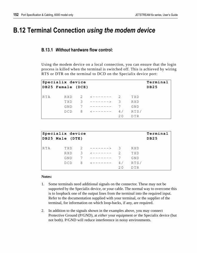
$/* �� ���-���%��������H����*��,��&&&�����*���*� ������������� �������� ��������
gin ng
this .
@%$* �� ��!��� �!!�����!� �������������������
@%$+%$� ����� ���� �3� �����3���!� ���
Using the modem device on a local connection, you can ensure that the loprocess is killed when the terminal is switched off. This is achieved by wiriRTS or DTR on the terminal to DCD on the Specialix device port:
Notes:
1. Some terminals need additional signals on the connector. These may not be supported by the Specialix device, or your cable. The normal way to overcomeis to loopback one of the output lines from the terminal into the required inputRefer to the documentation supplied with your terminal, or the supplier of the terminal, for information on which loop-backs, if any, are required.
2. In addition to the signals shown in the examples above, you may connect Protective Ground (P/GND), at either your equipment or the Specialix device (but not both). P/GND will reduce interference in noisy environments.
Specia l ix device TerminalDB25 Female (DCE) DB25
RTA RXD 2 <——————— 2 TXDTXD 3 ———————> 3 RXDGND 7 ———————- 7 GNDDCD 8 <——————— 4/
20RTS/DTR
Specia l ix device TerminalDB25 Male (DTE) DB25
RTA TXD 2 ———————> 3 RXDRXD 3 <——————— 2 TXDGND 7 ———————- 7 GNDDCD 8 <——————— 4/
20RTS/DTR

������������� �������� �������� �� ���-���%��������H����*��,��&&&�����*���*� $/+
. If tailed
�� ��!��� �!!�����!� �������������������
Without hardware flow control
<��!��!���=
with a Specialix RJ45 connector on a direct (1:1) connection(no structured cabling system present):
Notes:
1. In addition to the signals shown in the examples above, you may connect Protective Ground (P/GND) if you have shielded twisted-pair (STP) cable. Connect P/GND at either your equipment or the Specialix device (but not both). P/GND will reduce interference in noisy environments.
2. the example for RJ45 connector shown above is for shielded RJ45 ports onlyyou have non-shielded RJ45 ports use the pin-outs for the Specialix device dein Section B.6.
(shielded RJ45 ports only;- see note 2. below)
Specia l ix device TerminalRJ45 DB25
RXD 6 <———————— 2 TXDTXD 5 —————--—> 3 RXDS/GND 4 ———————- 7 S/GNDDCD 1 <———————— 4/
20RTS/DTR

$/. �� ���-���%��������H����*��,��&&&�����*���*� ������������� �������� ��������
gin ng
ware
t e ctor .
�� ��!��� �!!�����!� �������������������
@%$.%*� ������� �3� �����3���!� ���
Using the modem device on a local connection, you can ensure that the loprocess is killed when the terminal is switched off. This is achieved by wiriRTS on the terminal to DCD on the Specialix device port:
Notes:
1. The above examples assume that DTR on the terminal is being used for hardflow control.
If you are using RTS on the terminal as the hardware flow control pin, connecDTR on the Terminal to DCD on the Specialix device, and connect RTS on thterminal to either RTS or CTS on the Specialix device (RTS if Specialix conneis female (wired as DCE); CTS if Specialix connector is male (wired as DTE))
2. In addition to the signals shown in the examples above, you may connect Protective Ground (P/GND), at either your equipment or the Specialix device (but not both). P/GND will reduce interference in noisy environments.
Specia l ix device TerminalDB25 Female (DCE) DB25
RXD 2 <——————— 2 TXDTXD 3 ———————> 3 RXDRTS 4 <——————— 20 DTRGND 7 ———————— 7 GNDDCD 8 <——————— 4 RTS
Specia l ix device TerminalDB25 Male (DTE) DB25
TXD 2 ———————> 3 RXDRXD 3 <——————— 2 TXDCTS 5 <——————— 20 DTRGND 7 ———————- 7 GNDDCD 8 <——————— 4 RTS

������������� �������� �������� �� ���-���%��������H����*��,��&&&�����*���*� $//
al
nto the ed.
3. If your terminal still needs additional signals on the connector, note that thesesignals may not be supported by the Specialix device, or your cable. The normway to overcome this is to loopback one of the output lines from the terminal ithe required input. Refer to the documentation supplied with your terminal, or supplier of the terminal, for information on which loop-backs, if any, are requir
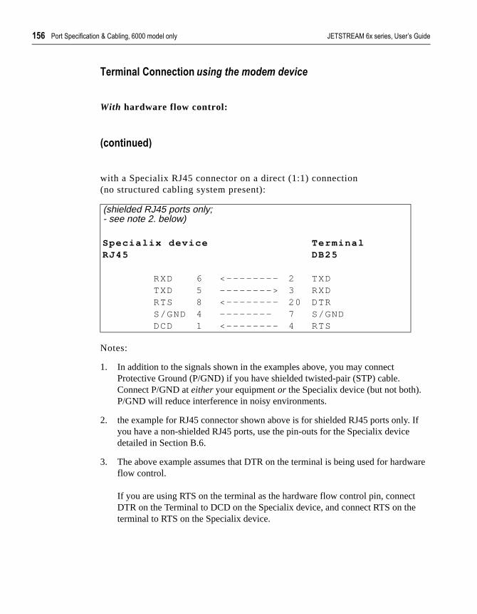
$/ �� ���-���%��������H����*��,��&&&�����*���*� ������������� �������� ��������
. If
ware
t e
�� ��!��� �!!�����!� �������������������
With hardware flow control:
<��!��!���=
with a Specialix RJ45 connector on a direct (1:1) connection(no structured cabling system present):
Notes:
1. In addition to the signals shown in the examples above, you may connect Protective Ground (P/GND) if you have shielded twisted-pair (STP) cable. Connect P/GND at either your equipment or the Specialix device (but not both). P/GND will reduce interference in noisy environments.
2. the example for RJ45 connector shown above is for shielded RJ45 ports onlyyou have a non-shielded RJ45 ports, use the pin-outs for the Specialix devicedetailed in Section B.6.
3. The above example assumes that DTR on the terminal is being used for hardflow control.
If you are using RTS on the terminal as the hardware flow control pin, connecDTR on the Terminal to DCD on the Specialix device, and connect RTS on thterminal to RTS on the Specialix device.
(shielded RJ45 ports only;- see note 2. below)
Specia l ix device TerminalRJ45 DB25
RXD 6 <———————— 2 TXDTXD 5 —————--—> 3 RXDRTS 8 <———————— 20 DTRS/GND 4 ———————- 7 S/GNDDCD 1 <———————— 4 RTS

������������� �������� �������� �� ���-���%��������H����*��,��&&&�����*���*� $/1
@%$/ ������
@%$%$� �� ����<$�$=���!!�����!��
Notes:
1. In addition to the signals shown in the examples above, you may connect Protective Ground (P/GND), at either your equipment or the Specialix device (but not both). P/GND will reduce interference in noisy environments.
Special ix device ModemDB25 Female (DCE) DB25
RXD 2 <——————— 3 RXD ModemTXD 3 ———————> 2 TXDRTS 4 <——————— 5 CTSCTS 5 ———————> 4 RTSDSR 6 ———————> 20 DTRGND 7 ——————— 7 GNDDCD 8 <——————— 8 DCDDTR 20 <——————— 6 DSR
Specia l ix device ModemDB25 Male (DTE) DB25
TXD 2 ———————> 2 TXD ModemRXD 3 <——————— 3 RXDRTS 4 ———————> 4 RTSCTS 5 <——————— 5 CTSDSR 6 <——————— 6 DSRGND 7 ——————— 7 GNDDCD 8 <——————— 8 DCDDTR 20 ———————> 20 DTR

$/2 �� ���-���%��������H����*��,��&&&�����*���*� ������������� �������� ��������
m
. If tailed
������E����������!!�����!�;
��!��!����
with a Specialix RJ45 connector and a direct (1:1) connection to the mode(no structured cabling system present):
Notes:
1. at the modem, signal RXD is received data from the PSTN; signal TXD is transmitted data to the PSTN.
2. In addition to the signals shown in the examples above, you may connect Protective Ground (P/GND) if you have shielded twisted-pair (STP) cable. Connect P/GND at either your equipment or the Specialix device (but not both). P/GND will reduce interference in noisy environments.
3. the example for RJ45 connector shown above is for shielded RJ45 ports onlyyou have non-shielded RJ45 ports use the pin-outs for the Specialix device dein Section B.6.
(shielded RJ45 ports only;- see note 2. below)
Specia l ix device ModemRJ45 DB25
RXD 6 <———————— 3 RXDTXD 5 —————--—> 2 TXDRTS 8 <———————— 5 CTSCTS 7 —————--—> 4 RTSDSR 2 —————--—> 20 DTRS/GND 4 ———————- 7 S/GNDDCD 1 <———————— 8 DCDDTR 3 <———————— 6 DSR

������������� �������� �������� �� ���-���%��������H����*��,��&&&�����*���*� $/4
PC
PC
@%$1 � ��<'@4���!!���� �=
���������!!�����!��
Note:
1. In addition to the signals shown in the examples above, you may connect Protective Ground (P/GND), at either your equipment or the Specialix device (but not both). P/GND will reduce interference in noisy environments.
2. if your PC is fitted with a DB25 connector, use the same DB25 pin-outs as formodems, shown in Section B.15 Modems
Special ix device PCDB25 Female (DCE) DB9
TXD 3 ———————> 2 RXDRXD 2 <——————— 3 TXDCTS 5 ———————> 8 CTSRTS 4 <——————— 7 RTSGND 7 ——————— 5 GNDDTR 20 <——————— 4 DTRDSR 6 ———————> 6 DSR
Specia l ix device PCDB25 Male (DTE) DB9
TXD 2 ———————> 2 RXDRXD 3 <——————— 3 TXDRTS 4 ———————> 8 CTSCTS 5 <——————— 7 RTSGND 7 ——————— 5 GNDDSR 6 <——————— 4 DTRDTR 20 ———————> 6 DSR

$) �� ���-���%��������H����*��,��&&&�����*���*� ������������� �������� ��������
. If tailed
� ;����������!!�����!�;
<��!��!���=�
1. if your PC is fitted with a DB25 connector, use the same DB25 pin-outs as formodems, shown in Section B.15 Modems
2. we assume you are connecting your PC directly to the Specialix device (no structured cabling system).
3. In addition to the signals shown in the examples above, you may connect Protective Ground (P/GND) if you have shielded twisted-pair (STP) cable. Connect P/GND at either your equipment or the Specialix device (but not both). P/GND will reduce interference in noisy environments.
4. the example for RJ45 connector shown above is for shielded RJ45 ports onlyyou have non-shielded RJ45 ports use the pin-outs for the Specialix device dein Section B.6.
(shielded RJ45 ports only;- see note 4. below)
Specia l ix device PCRJ45 DB9
TXD 5 —————--—> 3 TXDRXD 6 <———————— 2 RXDRTS 8 <———————— 7 RTSCTS 7 —————--—> 8 CTSS/GND 4 ———————- 5 S/GND

������������� �������� �������� �� ���-���%��������H����*��,��&&&�����*���*� $$
), at
r
@%$2 �� ����� �!�� �
@%$4%$� 3����������������3���!� ��
Notes on both examples:
1. In addition to the signals shown, you may connect Protective Ground (P/GNDeither your equipment or the Specialix device (but not both). P/GND will reduceinterference in noisy environments.
2. Some printers require additional pins to be held high (connected). Check youprinter’s documentation and follow any instructions.
Specia l ix device Pr interDB25 Female DCE DB25
RXD 2 <——————— 2 TXDTXD 3 ———————> 3 RXDGND 7 ———————— 7 GND
Specia l ix device Pr interDB25 Male DTE DB25
TXD 2 ———————> 3 RXDRXD 3 <——————— 2 TXDGND 7 ———————— 7 GND

$* �� ���-���%��������H����*��,��&&&�����*���*� ������������� �������� ��������
er
ed in
r
�� ����� �!�� �E����������!!�����!�;�
with software flow control
<��!��!���=
with a Specialix RJ45 connector and a direct (1:1) connection to the print(no structured cabling system present):
Notes:
1. the example for RJ45 connector shown above is for shielded ports only. If youhave non-shielded RJ45 ports, use the pin-outs for the Specialix device detailSection B.6.
2. In addition to the signals shown in the examples above, you may connect Protective Ground (P/GND) if you have shielded twisted-pair (STP) cable. Connect P/GND at either your equipment or the Specialix device (but not both). P/GND will reduce interference in noisy environments.
3. Some printers require additional pins to be held high (connected). Check youprinter’s documentation and follow any instructions.
(shielded RJ45 ports only;- see note 1. below)
Specia l ix device Pr interRJ45 DB25
RXD 6 <———————— 2 TXDTXD 5 —————--—> 3 RXDS/GND 4 ———————- 7 S/GND

������������� �������� �������� �� ���-���%��������H����*��,��&&&�����*���*� $+
your
), at
r
�� ����� �!�� �;����������!!�����!�;���!��!����
@%*)%*� 3���������������3���!� ��
Notes on both examples:
1. Printers have independent hardware flow control, using their DTR pin. Check printer is doing the same.
2. In addition to the signals shown, you may connect Protective Ground (P/GNDeither your equipment or the Specialix device (but not both). P/GND will reduceinterference in noisy environments.
3. Some printers require additional pins to be held high (connected). Check youprinter’s documentation and follow any instructions.
Specia l ix device Pr interDB25 Female DCE DB25
RXD 2 <——————— 2 TXDTXD 3 ———————> 3 RXDRTS 4 <——————— 20 DTRGND 7 ———————— 7 GND
Specia l ix device Pr interDB25 Male DTE DB25
TXD 2 ———————> 3 RXDRXD 3 <——————— 2 TXDCTS 5 <——————— 20 DTRGND 7 ———————— 7 GND

$. �� ���-���%��������H����*��,��&&&�����*���*� ������������� �������� ��������
er
ed in
our
r
�� ����� �!�� �E����������!!�����!�;�
with hardware flow control
<��!��!���=
with a Specialix RJ45 connector and a direct (1:1) connection to the print(no structured cabling system present):
Notes:
1. the example for RJ45 connector shown above is for shielded ports only. If youhave non-shielded RJ45 ports, use the pin-outs for the Specialix device detailSection B.6.
2. the printer has independent hardware flow control, using its DTR pin. Check yprinter is doing the same.
3. In addition to the signals shown in the examples above, you may connect Protective Ground (P/GND) if you have shielded twisted-pair (STP) cable. Connect P/GND at either your equipment or the Specialix device (but not both). P/GND will reduce interference in noisy environments.
4. Some printers require additional pins to be held high (connected). Check youprinter’s documentation and follow any instructions.
(shielded RJ45 ports only;- see note 1. below)
Specia l ix device Pr interRJ45 DB25
RXD 6 <———————— 2 TXDTXD 5 ————————> 3 RXDRTS 8 <———————— 20 DTRS/GND 4 ————————— 7 S/GND

������������� �������� �������� �� ���-���%��������H����*��,��&&&�����*���*� $/
ns,
ction ure hed,
nect
@%*$ �� ���� ��� ����!,��������
This section details structured cabling systems. For direct (1:1) connectiogo to Section B.7 Direct (1:1) Connections.
&�����
1. In the connection examples which follow, the signals shown refer to the conneat the end of the cabling system to which your equipment is attached - see Fig15. At the other end of the cabling system, where the Specialix device is attacwe assume - and recommend - you use a straight-through RJ45 cable to conour Specialix device to the cabling system.
F�,� ��#) �� ���� ������*��,���������� � ������

$ �� ���-���%��������H����*��,��&&&�����*���*� ������������� �������� ��������
ot be this r of
ins. te
an
ctor
2. Within the structured cabling system, we presume you use straight-through cabling, i.e. pin 1 to pin 1, pin 2 to pin 2, etc.
3. Some user equipment need additional signals on the connector. These may nsupported by the Specialix device, or your cable. The normal way to overcomeis to loopback - on the your equipment - one of the output lines to the requiredinput. Refer to the documentation supplied with your equipment, or the suppliethe equipment, for information on which loop-backs, if any, are required.
4. At each end of the cable, you must terminate all pairs of wires on connector pAn unconnected wire will receive electromagnetic radiation and possibly creainterference in the cable.
5. If you have wiring other than shown in the connection examples, and DCD is input on your equipment, ensure that it is not connected to DCD in the Specialix device.
6. On the RJ45 connector, Protective Ground (P/GND) terminates on the conneand so does not have a pin number.

������������� �������� �������� �� ���-���%��������H����*��,��&&&�����*���*� $1
the
@%**%$� ������� �!!�����!�
In this section we show example connections between Specialix ports andfollowing devices:
Terminals
structured cabling system Section B.23.2Terminal Connection using the modem device
Section B.24.3
Modems
structured cabling system Section B.25.4
PCs (DB9 connectors)
structured cabling system Section B.26.5
Serial Printers
structured cabling system Section B.27.6

$2 �� ���-���%��������H����*��,��&&&�����*���*� ������������� �������� ��������
type s of
.
e 60
e a
�� ��!���;����������!!�����!��
@%*+%*� �� ���� ��������!,�������
With a structured cabling system, use the example below to connect any of terminal. The pins and signals refer to the end of the cabling system towhich the terminal is attached - see Figure 15. We have shown the signala Wyse 60 terminal; for any other type of terminal, refer to the product’s documentation.
Notes:
1. in addition to the signals shown in the examples above, you may connect Protective Ground (P/GND) if you have shielded twisted-pair cable. Connect P/GND at either your equipment or the interface to cabling system (but not both)P/GND will reduce interference in noisy environments.
2. meaning of | :the DCD and DTR signals to the interface to the cabling systemoriginate jointly on the RTS pin at the terminal.
3. the DCD pin at the terminal is not connected (n/c); (devices other than the Wysmay require that the DCD pin is held high).
4. at the end of the cabling system to which the Specialix device is attached, usstraight-through cable.
(- see note 2. below about the Specialix RJ45 connectors
In ter face to cabl ing system TerminalRJ45 DB25
RXD 6 <———————— 2 TXDTXD 5 ————————> 3 RXDRTS 8 <———————— 20 DTRCTS 7 ————————> 5 CTSDSR 2 ————————> 6 DSRS/GND 4 ———————— 7 S/GNDDCD 1 <———————|
4 RTSDTR 3 <———————|
(n/c) DCD

������������� �������� �������� �� ���-���%��������H����*��,��&&&�����*���*� $4
. If
to le) to
d
5. the example for RJ45 connector shown above is for shielded RJ45 ports onlyyou have non-shielded RJ45 ports, use the pin-outs for the Specialix device detailed in Section B.6.
6. the minimum connection requirement is the RXD/TXD, TXD/RXD, RTS/RTS or DTR, CTS/CTS (if input flow control required) and S/GND signals (InterfaceCabling System/Terminal). The other pins may be connected (as in our exampensure minimum interference from unconnected pins.
7. for general advice on structured cabling systems, see Section B.21 StructureCabling Systems.
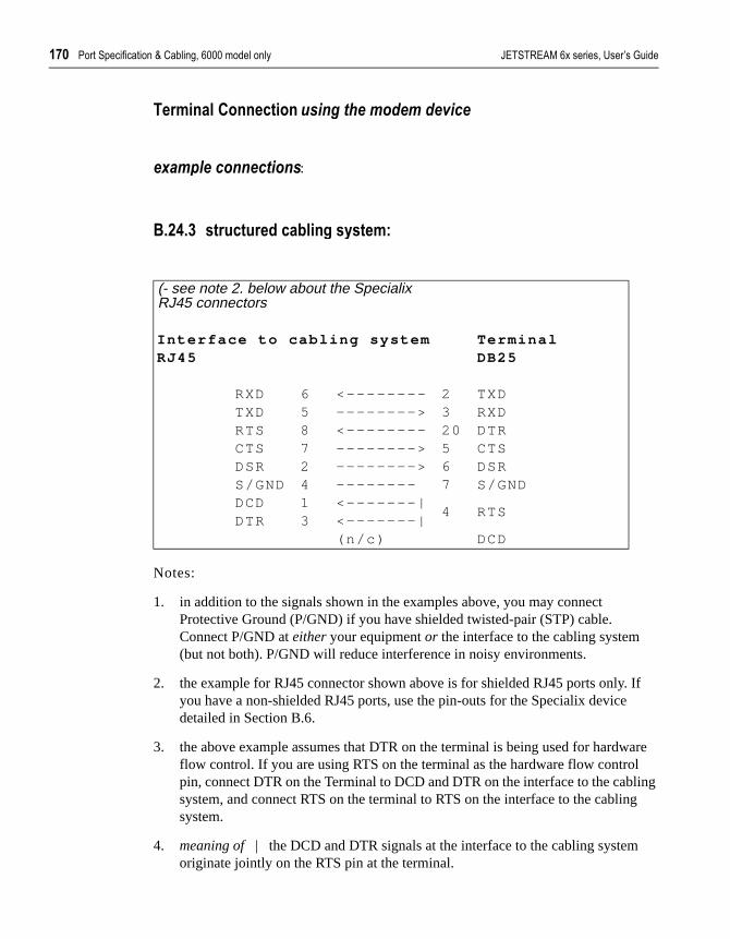
$1) �� ���-���%��������H����*��,��&&&�����*���*� ������������� �������� ��������
. If
are l ling g
�� ��!��� �!!�����!� �������������������
������������������:
@%*.%+� �� ���� ��������!,��������
Notes:
1. in addition to the signals shown in the examples above, you may connect Protective Ground (P/GND) if you have shielded twisted-pair (STP) cable. Connect P/GND at either your equipment or the interface to the cabling system (but not both). P/GND will reduce interference in noisy environments.
2. the example for RJ45 connector shown above is for shielded RJ45 ports onlyyou have a non-shielded RJ45 ports, use the pin-outs for the Specialix devicedetailed in Section B.6.
3. the above example assumes that DTR on the terminal is being used for hardwflow control. If you are using RTS on the terminal as the hardware flow contropin, connect DTR on the Terminal to DCD and DTR on the interface to the cabsystem, and connect RTS on the terminal to RTS on the interface to the cablinsystem.
4. meaning of | the DCD and DTR signals at the interface to the cabling systemoriginate jointly on the RTS pin at the terminal.
(- see note 2. below about the Specialix RJ45 connectors
In ter face to cabl ing system TerminalRJ45 DB25
RXD 6 <———————— 2 TXDTXD 5 ————————> 3 RXDRTS 8 <———————— 20 DTRCTS 7 ————————> 5 CTSDSR 2 ————————> 6 DSRS/GND 4 ———————— 7 S/GNDDCD 1 <———————|
4 RTSDTR 3 <———————|
(n/c) DCD

������������� �������� �������� �� ���-���%��������H����*��,��&&&�����*���*� $1$
he nce
5. the minimum connection requirement is the RXD/TXD, TXD/RXD, RTS/DTR, S/GND and DCD-DTR/RTS signals (Interface to Cabling System/Terminal). Tother pins may be connected (as in our example) to ensure minimum interferefrom unconnected pins.

$1* �� ���-���%��������H����*��,��&&&�����*���*� ������������� �������� ��������
the
details ailed
d
������;����������!!�����!��
@%*/%.� �� ���� ��������!,�������
with a structured cabling system present, the example below is shown at modem end - see Figure 15; (use a straight-through cable at the Specialixdevice end).
Notes:
1. at the modem, signal RXD is received data from the PSTN; signal TXD is transmitted data to the PSTN.
2. in addition to the signals shown in the examples above, you may connect Protective Ground (P/GND) if you have shielded twisted-pair (STP) cable. Connect P/GND at either your equipment or the interface to cabling system (but not both). P/GND will reduce interference in noisy environments.
3. at the Specialix device we assume you are using shielded RJ45 ports (as per in Section B.5). If you have non-shielded RJ45 ports use the pin numbers detin Section B.6.
4. for general advice on structured cabling systems, see Section B.21 StructureCabling Systems.
(- shielded RJ45 ports only; see note 3. below)
In ter face to cabl ing system ModemRJ45 DB25
RXD 6 <———————— 3 RXDTXD 5 —————--—> 2 TXDRTS 8 <———————— 5 CTSCTS 7 —————--—> 4 RTSDSR 2 —————--—> 20 DTRS/GND 4 ———————- 7 S/GNDDCD 1 <———————— 8 DCDDTR 3 <———————— 6 DSR
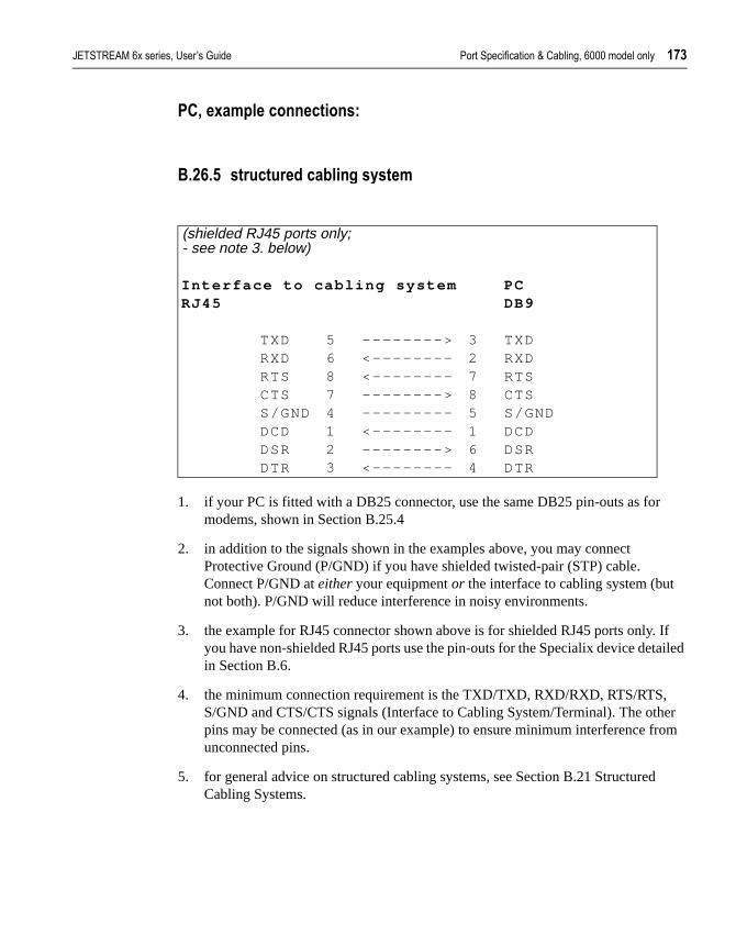
������������� �������� �������� �� ���-���%��������H����*��,��&&&�����*���*� $1+
. If tailed
er rom
d
� ;����������!!�����!��
@%*%/� �� ���� ��������!,�������
1. if your PC is fitted with a DB25 connector, use the same DB25 pin-outs as formodems, shown in Section B.25.4
2. in addition to the signals shown in the examples above, you may connect Protective Ground (P/GND) if you have shielded twisted-pair (STP) cable. Connect P/GND at either your equipment or the interface to cabling system (but not both). P/GND will reduce interference in noisy environments.
3. the example for RJ45 connector shown above is for shielded RJ45 ports onlyyou have non-shielded RJ45 ports use the pin-outs for the Specialix device dein Section B.6.
4. the minimum connection requirement is the TXD/TXD, RXD/RXD, RTS/RTS, S/GND and CTS/CTS signals (Interface to Cabling System/Terminal). The othpins may be connected (as in our example) to ensure minimum interference funconnected pins.
5. for general advice on structured cabling systems, see Section B.21 StructureCabling Systems.
(shielded RJ45 ports only;- see note 3. below)
In ter face to cabl ing system PCRJ45 DB9
TXD 5 ————————> 3 TXDRXD 6 <———————— 2 RXDRTS 8 <———————— 7 RTSCTS 7 ————————> 8 CTSS/GND 4 ————————— 5 S/GNDDCD 1 <———————— 1 DCDDSR 2 ————————> 6 DSRDTR 3 <———————— 4 DTR

$1. �� ���-���%��������H����*��,��&&&�����*���*� ������������� �������� ��������
the
on
hat
may e
�� ����� �!�� �;����������!!�����!��
@%*1%� �� ���� ��������!,�������
with a structured cabling system present, the example below is shown at printer end; (use a straight-through cable at the Specialix device end).
Notes:
1. meaning of | :the DCD and DTR wires at the cabling system originate jointly the RTS pin at the printer.
2. the DCD pin at the printer is not connected (n/c); (other printers may require tthe DCD pin is held high).
3. the minimum connection requirement is the RXD/TXD, TXD/RXD, RTS/DTR and S/GND connections (Interface to Cabling System/Printer). The other pins be connected (as in our example) to ensure that there is minimum interferencfrom unterminated pins.
4. in addition to the signals shown in the examples above, you may connect Protective Ground (P/GND) if you have shielded twisted-pair (STP) cable. Connect P/GND at either your equipment or the interface to cabling system (but not both). P/GND will reduce interference in noisy environments.
5. the above example applies to a printer using both hardware and software flowcontrol.
(shielded RJ45 ports only - see note 6. below)
In ter face to cabl ing system PrinterRJ45 DB25
RXD 6 <———————— 2 TXDTXD 5 ————————> 3 RXDRTS 8 <———————— 20 DTRCTS 7 ————————> 5 CTSDSR 2 ————————> 6 DSRS/GND 4 ————————— 7 S/GNDDCD 1 <———————|
4 RTSDTR 3 <———————|
(n/c) DCD

������������� �������� �������� �� ���-���%��������H����*��,��&&&�����*���*� $1/
. If tailed
6. the example for RJ45 connector shown above is for shielded RJ45 ports onlyyou have non-shielded RJ45 ports use the pin-outs for the Specialix device dein Section B.6.
7. for general advice on structured cabling systems, see Section B.21

$1 �� ���-���%��������H����*��,��&&&�����*���*� ������������� �������� ��������
el
@%*2 �� ������'@*/��� �
This port provides a Centronics-type interface for Parallel printers. Parallcables use a straight 25-way connection.
Table 10Parallel pin-outs
* = Active low
Pin Circuit Direction Function1 STROBEN* Output PSTROBE2 D0 Output DATA 13 D1 Output DATA 24 D2 Output DATA 35 D3 Output DATA 46 D4 Output DATA 57 D5 Output DATA 68 D6 Output DATA 79 D7 Output DATA 810 PACKN* Input ACK11 PBUSY Input BUSY12 PPE Input PE13 PSLCT Input SLCT14 AUTOFDXT* Output AUTOFEED15 PERRORN* Input FAULT16 PINITN* Output INPUT PRIME17 PSLINN* Output SLCT IN18 GND — GROUND19 GND — GROUND20 GND — GROUND21 GND — GROUND22 GND — GROUND23 GND — GROUND24 GND — GROUND25 GND — GROUND

������������� �������� �������� �� ���-���%��������H����*��,��&&&�����*���*� $11
est ill
The
d to
see
@%*4 ��*+*���./�7���0����������� ��
These ports have the RXD+ and RXD- pins electrically isolated from the rof the unit using opto-isolators. This provides two advantages: the signal wnot pick up interference, and power surges or sparks caused by voltage changes will not be transmitted.
Further noise reductions can be achieved by using software flow control. pin-outs for these ports are as follows:
���*��##
��0:0���7)�C-��=
���*�����-��=����
Pin 6 (Ground) should be used as TXD+; pin 7 (CTS) should be connectepin 2 (RTS-) on the peripheral device.
The pins in the RJ45 socket are located at the top, with pin 1 on the left (Figure 14).
Pin Si gnal Direction Function1 Chassis — Chassis Ground2 RTS- Output Inverse RTS3 TXD- Output Inverse TXD4 RXD+ Input Receive Data5 RXD- Input Inverse RXD6 Ground — Signal Ground7 CTS Input Clear To Send8 Chassis — Chassis Ground

$12 �� ���-���%��������H����*��,��&&&�����*���*� ������������� �������� ��������
the
to
and
@%+) ��.**�'@*/��� ��
These ports provide a full RS422 interface for serial devices. When wiringwith RS422 ports refer to the documentation supplied with the device, or suppliers of the device, for wiring instructions.
RS422 twisted-pair cable allows you to run a serial device at 115.2Kb up 1km from the Specialix device port.
The RS422 D25 pin descriptions are:
���*��#0
��700�9/0)�-��=
����
The two wires (+ and -) for each signal must be twisted together to form apair.
The names of some of these signals are often used in reverse. Here, CTSDTR are outputs, RTS and DSR are inputs.
��! � ���� '� �����! ��!����!1 Chassis Connects to case2 RXD+ Input Receive Data3 TXD+ Output Transmit Data4 RTS+ Input Receive Hardware Flow
Control5 CTS+ Output Transmit Hardware Flow
Control6 DTR+ Output Data Terminal Ready7 Ground — Connects to logic 0V8 DSR+ Input Data Set Ready10 DSR- Input Inverse DSR13 CTS- Output Inverse CTS14 RXD- Input Inverse RXD16 TXD- Output Inverse TXD18 DTR- Output Inverse DTR19 RTS- Input Inverse RTS20 DCD+ Input Data Carrier Detect21 RI- Input Inverse RI22 RI+ Input Ring Indicator23 DCD- Input Inverse DCD

������������� �������� �������� �� ���-���%���������H����*��,$�)&&�����*���*� $14
ors o to
� - - � � � � � �
�� ��������������!��C� ����!,�/))��������!��
%$ 7>� >��3
This appendix describes pin specifications for the types of Specialix connecton the 6500 and 6501 models only. For detail on the 6000 and 6001 model gAppendix B (Port Specification & Cabling, 6000 model only).
������!��!���������������!���� ��
• AUI 15-way female D-type connector, Section C.2
• RJ45 10BaseT port, Section C.3
• RS232 shielded RJ45 ports, Section C.4

$2) �� ���-���%���������H����*��,$�)&&�����*���*� ������������� �������� ��������
nector
��!�������������!�
%* �5(�$/03����������'0�������!!����
Note These pin-outs refer to the 6500 and 6501 models only.
%+ ��./�$)@������� �
Note These pin-outs refer to the 6500 and 6501 models only. On these models this conis on the rear of the product.
Pin Si gnal Pin Si gnal1 Ground/chassis link 9 Collision-2 Collision+ 10 Data Out-3 Data Out+ 11 Ground4 Ground 12 Data In-5 Data In+ 13 +12 volt6 Ground 14 Ground7 no connection 15 no connection8 Ground
Pin Si gnal Function1 TXD+ Transmit Data+2 TXD- Transmit Data-3 RXD+ Receive Data+4 n/c no connection5 n/c no connection6 RXD- Receive Data-7 n/c no connection8 n/c no connection

������������� �������� �������� �� ���-���%���������H����*��,$�)&&�����*���*� $2$
nector
%. ��*+*������������./��� ��
Note These pin-outs refer to the 6500 and 6501 models only. On these models this conis on the front of the product.
Pin Si gnal Direction Function1 DCD IN Data Carrier Detect2 DSR OUT Data Set Ready3 DTR IN Data Terminal Ready4 Signal Ground - Connects to Logic 0V5 TXD OUT Transmit Data6 RXD IN Receive Data7 CTS OUT Clear To Send8 RTS IN Request To SendShield Frame Ground - Connects to frame

$2* �� ���-���%���������H����*��,$�)&&�����*���*� ������������� �������� ��������

������������� �������� �������� � ���*��������, $2+
st ur
cialix
e
l to the
e
� - - � � � � � 9
� �����������!,
'%$ (!� �������!
This appendix contains solutions for problems that may arise while using theJETSTREAM.
If you bought your JETSTREAM from a registered Specialix Supplier, you mucontact their Technical Support department; they are qualified to deal with yoproblem.
If you are a registered Specialix Supplier, and bought your JETSTREAM fromSpecialix, please contact the Technical Support department of your nearest Specialix office. The addresses and telephone numbers of your nearest Speoffice are contained in Section D.6 Technical Support.
'%* ��!� ��������!������!�����#�
A good general communication check is as follows:
• ping your host; if you cannot ping at all, check the cabling between thJETSTREAM and your network. If you can ping but packet loss is reported, ping another host/device on the same network. You will appreciate whether the problem is specific to a host/device or generathe network. If there is a problem with the network check the state of network, including number of nodes.
• use the show route command (command line only). Is there a route to thhost? The show route command is explained in more detail at Section11.51 show route.

$2. � ���*��������, ������������� �������� ��������
n
k
.
e .
ll
'%+ � ���������!�� !���3�����������!,�������<�=
'%+%$ �!!��������������������!���
• if using DNS or DNS is required, ensure a nameserver is configured oyour JETSTREAM and is accessible (ping it).
• if not using DNS, ensure the host is configured in the host table. Checaccess to the host by pinging it using the host’s IP address.
'%+%* �!!������������������!���������!��3� #
ensure:
• the network address is correct.
• the subnet mask is set correctly and reflects the network configuration
• the broadcast address is set correctly and reflects the network configuration.
'%+%+ �!!������������������!��� ������!��3� #
• use the show route command to verify that there is a route to the remothost. If no gateway is specified, ensure a default gateway is specifiedPing the default gateway to check if it is working.
• Consider the situation beyond the gateway; e.g. are intermediate gateways and the remote host available? Also, check the messages returned by the show route command; e.g. that a particular host or gateway is unreachable.
'%+%. ������������������������ �����3���!����
• Earlier versions of JETSTREAM did not support static routing. If the route to this host goes through routers, make sure those routers are asending RIP packets.

������������� �������� �������� � ���*��������, $2/
r
n
al.
nu
'%. � ����������!,���� ��� ��!��
The following section concerns problems with the appearance of data on youterminal screen:
'%.%$ � ��������
• check your line settings (baud rate, stop bits, etc.)
'%.%* �����!,�����
• ensure the same type of flow control is set in both your terminal and othe JETSTREAM port.
'%.%+ �� ��!��� �����!�3��!����!,�������!��!,�������
• check that the terminal setup in the JETSTREAM matches your termin
• check that entries in the term file match your terminal setup.
• if using a PC, ensure the type of terminal emulation selected in your application matches those supported by the JETSTREAM. If you still have the problem, you may be suffering with poorly written terminal emulation in your application. Instead use the command line mode.
'%.%. -��!����!,�������!����!�#�����!���� �#����� �;�!����!,�
�����!��� ���� �������!��#�����3����!,%
The function keys on the keyboards of some terminals (e.g. Wyse 60) send character sequences which begin with ^a. This is the default screen switch character, or ‘hot- key’, which you use to switch between sessions. You can change your own screen switch character by using the ‘Set Environment’ meoption on the Set Up User menu (see Section 9.6 Changing your User Environment). A valid alternative would be ^b (hex=02). If you are the systemadministrator, you can change any user’s screen switch character using the ‘Change User’ option on the Users menu (see Section 5.5 Configure a User Account).

$2 � ���*��������, ������������� �������� ��������
,
the ers
'%.%/ -��!����!,�����3!��������� ��!�������!����!;������ ��
��>�!,�� ����������!,�� �3�#���%
• Use Ctrl-K, Ctrl-J, Ctrl-H and Ctrl-L for up, down, left and right respectively.
'%.% -��!��3�����!,�� �����������!����#����������� ��!�
����;�������� ��!����,���� ������ �������%
• Press ^r to redraw the screen.
'%/ 7��� �� ������
'%/%$ ��� � ����!��>�!���
• Implement load-balancing by distributing the processing. For exampletry not to cluster on the JETSTREAM devices which require high throughput.
• Ensure routes to/from your host are as direct as possible; e.g. ensureJETSTREAM is on the same network as your host so that bridges/routdo not act as bottlenecks.
• If your network is congested, subnet it with a bridge; however, bear inmind the recommendations in the previous paragraph.
'%/%* F�����!?����3!������������ ��������������%
• Make sure TFTP is enabled on the boot host and that the file(s) to bedownloaded have global read/write permission.
• If you are using TFTP with the secure option make sure you follow theinstructions in Section 8.4 Downloading Terminal Definitions.

������������� �������� �������� � ���*��������, $21
ore
k the e D
ter as for
'%/%+ (&(���� � ��!��� ��!��������:���:���:�� ��
This error indicates that you have exceeded the 80 character limit for one or mof the terminal capabilities defined in the reported file.
'%/%. (&(���� � ��!���!�����!��� ��!��������:���:���:�� ��
You have omitted the ‘=’ sign from the reported line.
'%/%/ @77��������!���3� #
• in the BOOTPTAB file on your host, enter all of the fields listed at Section 8.5.2 The BOOTPTAB file; i.e. all of ht, ha, ip, sm, etc.
• Check the hosts’ documentation for requirements on BOOTPTAB file entries.
'%/% ���'�� ������
On some operating systems, the system timeouts used to establish and breanetwork connections can disrupt the operation of MTSD. To avoid this, checkarguments you are using with MTSD commands. Type mtsd -help and see thapplicability of each command. In this manual, see Section 7.8.6 List of MTScommand options.
Include or take-out arguments which you feel are appropriate.
'%/%1 �!!�����!��,� ����!������� ������� ���!���!�������
Port 8 (the Console port) deliberately cannot be configured as silent and prinline types. This precaution prevents all JETSTREAM ports being configured silent or printer connections, thereby denying you access to the JETSTREAMconfiguration.
• To configure the console port as silent or printer line type, you must telnet into the JETSTREAM.

$22 � ���*��������, ������������� �������� ��������
ant
e a
nd
).
er
gs for
d
nd
'%/%2 ��� ,�!�������>� �
Problem:
All ports are set to direct or silent telnet/rlogin (i.e. direct to a host) and you wto get to the JETSTREAM login. Recovery procedure is:
• on port 8 (the console port) telnet/rlogin into the JETSTREAM (and selogin prompt from a host), wait until the host login has timed out and press <esc>. You should see a login to the JETSTREAM.
Problem:
You have a JETSTREAM already configured and,
- have lost, misconfigured or don't know the IP address of the JETSTREAM, a
- you cannot obtain a login on any port (including the console port), and
- you have lost or don't know your password
the recovery procedure is the same as for a lost password (see Section 8.12
Note the following:
• before you type in the magic string you will not see a login prompt. Aftyou have successfully typed in the magic string, you will see a login prompt.
• when you have successfully gained access to your unit, the line settinwill be set to factory default (see Section 1.8 Setting Up the Console) the duration of that login only. Other configuration information will be unchanged.
• Next time you login (using your preferred password) the original storeline settings will be restored.
Problem:
You have a JETSTREAM already configured and,
- you do know your password, but
- have lost, misconfigured or don't know the IP address of the JETSTREAM, a
- you cannot obtain a login on any port (including the console port)

������������� �������� �������� � ���*��������, $24
).
net TP
ts
st ur
The emergency recovery method is to use BOOTP (see Section 8.5 BOOTP
• Setup a host machine on your network to run BOOTP. Using the etheraddress of the JETSTREAM (printed on the base of the product) BOOwill assign the JETSTREAM a known IP address.
• Now, you should be able to telnet onto the JETSTREAM and change iIP address.
Using BOOTP to recover access to your JETSTREAM in this manner will preserve all configuration settings - apart from the IP address.
'% ����!���������� �
If you bought your JETSTREAM from a registered Specialix Supplier, you mucontact their Technical Support department; they are qualified to deal with yoproblem.
If you are a registered Specialix Supplier, and bought your JETSTREAM fromSpecialix, contact Specialix Technical Support at these offices:
'%%$ �� ���
United Kingdom
Specialix Europe Ltd. 3 Wintersells Road Byfleet Surrey KT14 7LFUK
Telephone: +44 (0) 1932 792555 (Support)+44 (0) 1932 792592 (Main SwitchBoard)
(previously, Main SwitchBoard was +44 (0) 1932 354254)
Facsimile: +44 (0) 1932 792593(was +44 (0) 1932 352781)
e-mail: [email protected]
ftp site: [email protected]. Use your e-mail address for your password.
web site: [email protected]

$4) � ���*��������, ������������� �������� ��������
log via
Bulletin Board Service. +44 (0) 1932 355654. All speeds up to 28800 Baud. Toin, the user id is ‘bbs’, the password ‘support’. The BBS can also be accessedour ftp site ftp.specialix.co.uk (see above).
France
Specialix Ltd. 13 Avenue Morane - Saulnier78140 VelizyFRANCETelephone: +33 (1) 34 63 0670Facsimile: +33 (1) 34 65 38 60
e-mail, ftp and www contact details, as for UK.
Germany
Specialix Ltd. Lyonerstrasse 14 D-60528 Frankfurt/MainGERMANYTelephone: +49 (0) 69 6655 4460Facsimile: +49 (0) 69 6655 4100
e-mail, ftp and www contact details, as for UK.
'%%* 5���
Specialix Inc. 745 Camden Avenue #129 Campbell CA95008-4146USATelephone: +1 (408) 378-7919(Freephone): +1 (800) 423-5364 (USA only)Facsimile: +1 (408) 378-0786
US support is open from 7am Pacific (10am Eastern) time until 5pm Pacific(8 Eastern) time.
E-mail: [email protected]
World Wide Web: [email protected]

������������� �������� �������� � ���*��������, $4$
BS mail
Bulletin Board Service (BBS). The US BBS can be accessed using the following numbers:
+1-408-378-4766 Hayes 2400 Baud
+1-408-378-4767 MultiTech 28800 Baud
+1-408-378-4768 MultiTech 28800 Baud
+1-408-378-4769 US Robotics 14400 Baud
To log into the BBS, the user id is guest and the password support. The Bcan also be accessed from our FTP site slxbbs.specialix.com. Use your e-address for your password.
'%%+ ��!,��� �
Specialix (Asia) Pte Ltd. Yu Li Industrial Building No 37 Lor 23 Sims Avenue #04-01/05Singapore 388371
Telephone: +65 (0) 749 1700Facsimile: +65 (0) 749 2003
Email: [email protected]
'%%. ���� ����
Specialix Pty Ltd. Unit 15a, 390 Eastern Valley WayRosevilleNSW 2069AUSTRALIA
Telephone: +61 (0) 2 417 3666Facsimile: +61 (0) 2 417 3791

$4* � ���*��������, ������������� �������� ��������

������������� �������� �������� �-����*��� � �����1/�9�%�������� $4+
� - - � � � � � �
���������� �>�����(@�'���!����!�
OBJECT TYPE SYNTAX ACCESS STATUS DEFINITION
ServerName DisplayString Read-write Mandatory The hostname of the JETSTREAM unit
freeSpace Gauge Read-only Mandatory The amount of free memory available on the JETSTREAM
swVersion DisplayString Read-only Mandatory The software version number
serverInfo ServerInfo Not accessible Mandatory A list of objects relating to general server information
domainName DisplayString Read-write Mandatory The domain name of the JETSTREAM unit
portsNumber INTEGER Read-only Mandatory The number of ports on the JETSTREAM unit
portsInfoTable SEQUENCE of PortsInfoEntry
Not accessible Mandatory The serial ports info table
portsInfoEntry PortsInfoEntry Not accessible Mandatory An entry in the PortsInfoTable, relating to an JETSTREAM port
portID INTERGER Read-only Mandatory An index that uniquely identifies the port
terminalType INTERGER {wyse60(1)vt100(2)ansi(3)dumb(4)term1(5)term2(6)term3(7)}
Read-write Mandatory The terminal type of the port

$4. �-����*��� � �����1/�9�%�������� ������������� �������� ��������
baudRate INTEGER {b75(1)b300(2)b600(3)b1200(4)b1800(5)b2400(6)b4800(7)b9600(8)b19200(9)b38400(10)b57600(11)b115200(12)}
Read-write Mandatory The baud rate of the port
dataBits INTEGER {d5(1)d6(2)d7(3)d8(4)}
Read-write Mandatory The number of databits used on the port
parity INTEGER {none (1)odd (2)even (3)}
Read-write Mandatory The parity of the port
stopBits INTEGER {s1 (1)s2 (2)}
Read-write Mandatory The number of stop bits used on the port
pages INTEGER {p1 (1)p2 (2)p3 (3)p4 (4)p5 (5)p6 (6)p7 (7)}
Read-write Mandatory The number of pages available on the port
defaultUser INTEGER Read-write Mandatory The default user of the port
validUser INTEGER {no (1)yes (2)}
Read-write Mandatory Is there a default user user of the port ?
OBJECT TYPE SYNTAX ACCESS STATUS DEFINITION

������������� �������� �������� �-����*��� � �����1/�9�%�������� $4/
modem INTEGER {off (1)on (2)}
Read-write Mandatory The modem status of the port
flowControl INTEGER {none (1)soft (2)hard (3)both (4)}
Read-write Mandatory The flow control being used on the port
lineType INTEGER {normal (1)directraw (2)silentraw (3)printer (4)directtelnet (5)silenttelnet (6)reversetelnet (7)reverseraw (8)bimodem (9)directlogin (10)silentlogin (11)}
Read-write Mandatory The type of connection being used on the port
hostPort INTEGER Read-write Mandatory The host TCP port assigned to the virtual circuit
mtsPort INTEGER Read-write Mandatory The TCP port assigned to the port
host INTEGER Read-write Mandatory The host for the virtual circuit
pinDCD INTEGER {off (1)on (2)}
Read-only Mandatory The current status of the port’s DCD pin. If the port is a Parallel port, ‘on’ means printer not busy, ‘off’ means printer busy
pinDTR INTEGER {off (1)on (2)}
Read-only Mandatory The current status of the port’s DTR pin. If the port is a serial port on a parallel module, pinDTR returns an error. If the port is a Parallel port, ‘on’ means error, ‘off’ means no error
OBJECT TYPE SYNTAX ACCESS STATUS DEFINITION
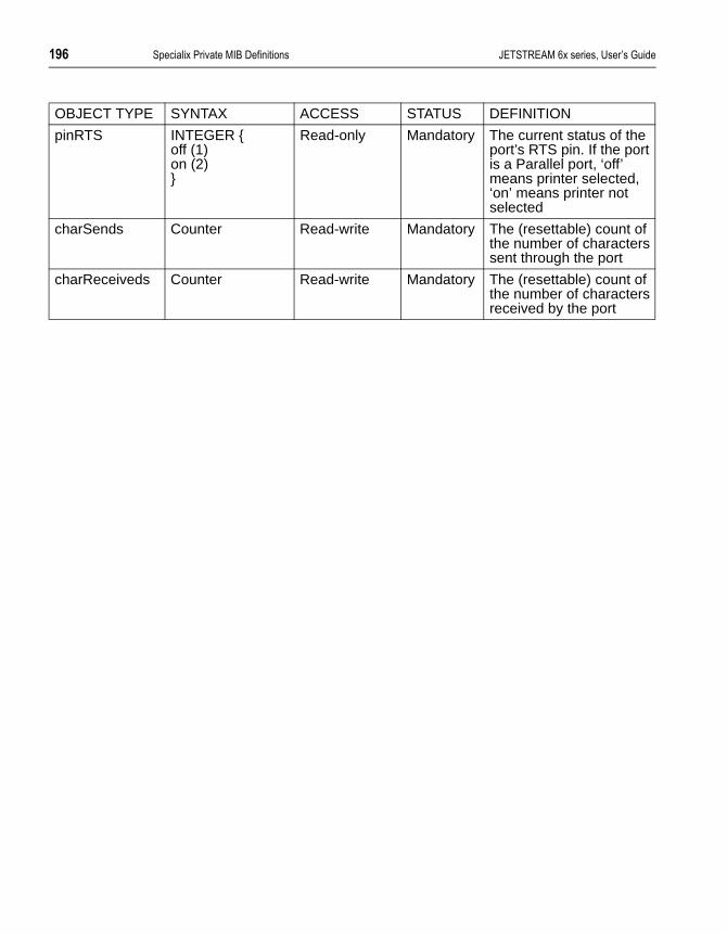
$4 �-����*��� � �����1/�9�%�������� ������������� �������� ��������
pinRTS INTEGER {off (1)on (2)}
Read-only Mandatory The current status of the port’s RTS pin. If the port is a Parallel port, ‘off’ means printer selected, ‘on’ means printer not selected
charSends Counter Read-write Mandatory The (resettable) count of the number of characters sent through the port
charReceiveds Counter Read-write Mandatory The (resettable) count of the number of characters received by the port
OBJECT TYPE SYNTAX ACCESS STATUS DEFINITION

������������� �������� �������� ���11�����E�J��������� �� $41
� - - � � � � � F
�� ((��!��8�G��������� ��
�%$ (!� �������!
This appendix contains the following:
• Section F.2 ASCII to Decimal and Hex Code Chart
• Section F.3 Binary to Hex Code Chart
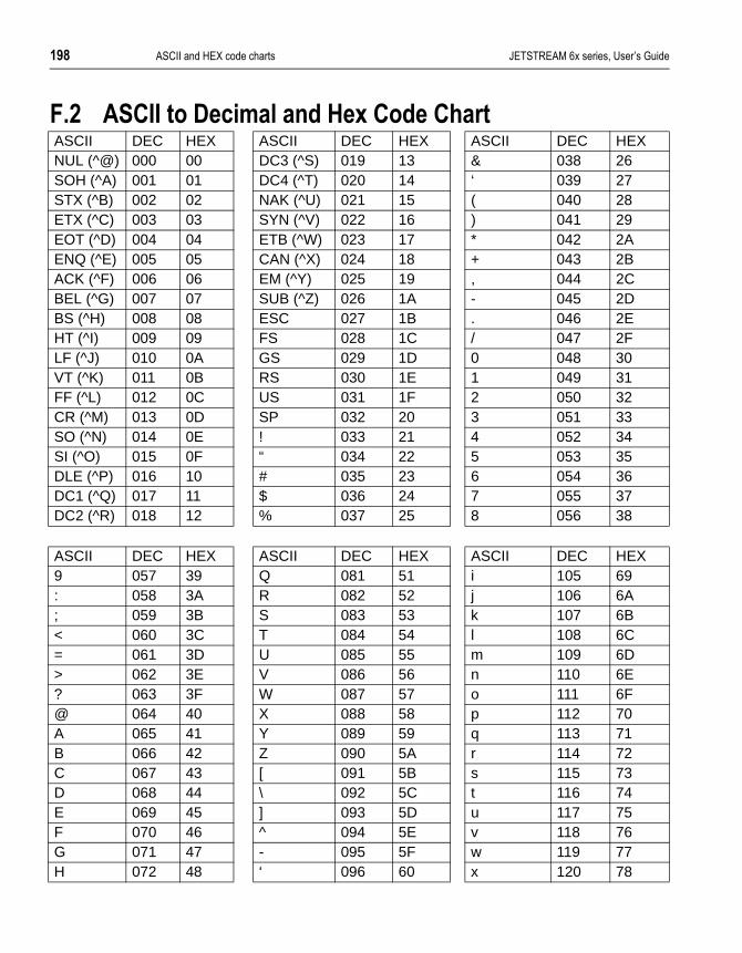
$42 ���11�����E�J��������� �� ������������� �������� ��������
�%* �� ((����'��������!��8�� ���� �� �ASCII DEC HEX ASCII DEC HEX ASCII DEC HEXNUL (^@) 000 00 DC3 (^S) 019 13 & 038 26SOH (^A) 001 01 DC4 (^T) 020 14 ‘ 039 27STX (^B) 002 02 NAK (^U) 021 15 ( 040 28ETX (^C) 003 03 SYN (^V) 022 16 ) 041 29EOT (^D) 004 04 ETB (^W) 023 17 * 042 2AENQ (^E) 005 05 CAN (^X) 024 18 + 043 2BACK (^F) 006 06 EM (^Y) 025 19 , 044 2CBEL (^G) 007 07 SUB (^Z) 026 1A - 045 2DBS (^H) 008 08 ESC 027 1B . 046 2EHT (^I) 009 09 FS 028 1C / 047 2FLF (^J) 010 0A GS 029 1D 0 048 30VT (^K) 011 0B RS 030 1E 1 049 31FF (^L) 012 0C US 031 1F 2 050 32CR (^M) 013 0D SP 032 20 3 051 33SO (^N) 014 0E ! 033 21 4 052 34SI (^O) 015 0F “ 034 22 5 053 35DLE (^P) 016 10 # 035 23 6 054 36DC1 (^Q) 017 11 $ 036 24 7 055 37DC2 (^R) 018 12 % 037 25 8 056 38
ASCII DEC HEX ASCII DEC HEX ASCII DEC HEX9 057 39 Q 081 51 i 105 69: 058 3A R 082 52 j 106 6A; 059 3B S 083 53 k 107 6B< 060 3C T 084 54 l 108 6C= 061 3D U 085 55 m 109 6D> 062 3E V 086 56 n 110 6E? 063 3F W 087 57 o 111 6F@ 064 40 X 088 58 p 112 70A 065 41 Y 089 59 q 113 71B 066 42 Z 090 5A r 114 72C 067 43 [ 091 5B s 115 73D 068 44 \ 092 5C t 116 74E 069 45 ] 093 5D u 117 75F 070 46 ^ 094 5E v 118 76G 071 47 - 095 5F w 119 77H 072 48 ‘ 096 60 x 120 78

������������� �������� �������� ���11�����E�J��������� �� $44
I 073 49 a 097 61 y 121 79J 074 4A b 098 62 z 122 7AK 075 4B c 099 63 { 123 7BL 076 4C d 100 64 | 124 7CM 077 4D e 101 65 } 125 7DN 078 4E f 102 66 ~ 126 7ESO 079 4F g 103 67 DEL 127 7FP 080 50 h 104 68
ASCII DEC HEX ASCII DEC HEX ASCII DEC HEX

*)) ���11�����E�J��������� �� ������������� �������� ��������
�%+ @�!� �����8�� ���� �� �
Notes:
To represent two letters/two numbers flow binary numbers sequentially, so :
0F is 0 followed by F, i.e. 0000 followed by 1111.
0F is therefore 00001111 in binary.
Likewise, the binary digits 10110100 would equate to:
1011 followed by 0100, which is B followed by 4;
therefore 10110100 is B4 in hex.
@�!� � 8�
&&&& &
&&&# #
&&#& 0
&&## :
&#&& 7
&#&# )
&##&
&### ?
#&&& 6
#&&# >
#&#& �
#&## /
##&& �
##&# 9
###& �
#### F

������������� �������� �������� ���D1�������� ����*��� � � *)$
are to a
ed erial
er of
als rk,
a e
ork-
� - - � � � � � �
� �:(���!���� ��!����� >� �
�%$ (!� �������!
The purpose of this appendix is to provide a background to, and general information on, Terminal Servers and the TCP/IP protocol suite, for those whoeither unfamiliar with the technology or need further information. The aim is provide sufficient information to allow installation and testing of products on TCP/IP network.
�%* �� ��!����� >� �
Traditionally, terminals, modems and printers have been directly attached to multi-user computer systems through the use of dedicated hardware containwithin the host computer system. Such hardware is normally described as a smultiplexor or multi-port card, and indeed Specialix makes a range of these products for use with PC bus technology systems.
An alternate, network-based, method of connection has been used by a numbproprietary system manufacturers, most notably IBM’s SNA-based 3270 communications controllers and DEC’s LAT network terminal server.
The advantage of such schemes revolve around the ability to connect terminsignificantly further from the host machine and, through a configurable netwoto provide connections to a number of hosts from a single terminal.
An example of such a scheme might be a manufacturing company that runs production database on one system, general accounts on another, and officeapplications on a third. A financial analyst may well require access to all thresystems, for different functions. Such a person could have three different terminals, a practice which has occurred in the past. However, through a netwbased connection, a single terminal can easily access many hosts.

*)* ���D1�������� ����*��� � � ������������� �������� ��������
s is the
e
ying offer with
der-is ded
) y
. P rial
In addition to the benefits of access to multiple hosts, terminal servers also offload the processing requirements associated with the handling of serial devices, line discipline etc.
Once the requirement for network-based access from terminals to such hostestablished, the need arises for a set of standards to determine and manageconnection methods. TCP/IP is one of these standards.
�%+ 8���� �
TCP/IP networking is generally associated with UNIX. Its origins, however, liwith the US government’s Defence Advance Research Projects Agency (DARPA).
DARPA sponsored the development of TCP/IP to provide a coherent suite ofnetwork protocols for ARPANET, which links key defence, government and research computer systems. Many of these sites use supercomputers, emploproprietary operating systems, but to encourage academic involvement, and broader access, DARPA funded the development of TCP/IP software for use ‘Berkeley Standard Distribution’ (BSD) UNIX.
By the mid-eighties, the National Science Foundation (NSF) had realised thevalue of ARPANET, but saw the benefit of expanding access to a wider community, it therefore funded the development of a higher-performance, wiaccess network system. Although the NSF still runs the major elements of thnetwork, access is available worldwide, primarily through access points proviby the academic community. The network is the INTERNET.
Perhaps because of its academic and research bias, but more likely out of commercial self-interest, the major computer vendors (primarily DEC and IBMhave tended to support but not encourage the use of TCP/IP. However, todathere is hardly any computer system that cannot be accessed using TCP/IP protocols.
With the growth in demand for remote access, two protocols were developedFirstly there was SLIP (Serial Line Interface Protocol) and then there was PP(Point to Point Protocol). By allowing the transmission of IP packets over a seline these protocols fuelled the remote access market.
Specialix support the SLIP and PPP protocols through their JETSTREAM 7xseries product range of Communication Servers.

������������� �������� �������� ���D1�������� ����*��� � � *)+
s.
sure s
e
, but tered
PA, ge ame he
n this ion,
ork,
�%. 6�����9��-����� ���&��3� #�
This guide primarily concentrates on TCP/IP running on Ethernet local area networks (LANs), however TCP/IP’s principal strength is that it also easily supports wide area connections, which after all are what the internet provideAccess to host systems distributed world-wide is as easy as accessing local machines.
�%/ &��3� #���� ����!,
To construct a worldwide internet, some mechanism has to be provided to eneach network node (or host) has a unique address. Because TCP/IP supportmany transmission media (not just Ethernet but also Token Ring, Pronet, ARCNET and various WAN link technologies), its addressing scheme must bindependent of the network connection method used.
All TCP/IP nodes have an ‘internet address’, these can be set autonomouslyto be connected to the internet, the address has to be provided by, and regiswith NSF. Details of this registration process are provided at the end of this chapter.
Internet addresses exist in three classes. The originators of the internet, DARassumed in the early design that a small number of sites, with potentially larnumbers of computers at each site, would be the norm. However once it becobvious that a broader academic and commercial involvement would occur, taddressing scheme had to be expanded to allow more sites.
The basic internet address is a 32 bit number. To allow ease of representatioaddress is broken into 4 octets (bytes) and reported in ‘dotted decimal’ notatthus:
nnn.nnn.nnn.nnn
where nnn can be any number in the range 0 to 255.
e.g. 128.213.120.151 or 192.65.144.23 or 1.0.0.1
All internet addresses are deemed to have two parts, one identifying the netwand the other the particular device. Three classes of address are supported:
�%/%$ ������
1 2 7 8 320 netid hostid

*). ���D1�������� ����*��� � � ������������� �������� ��������
sily with
s are .
of ress
use mes nce
e a lled
t of ing h the
The first format supports 128 networks of 16 million nodes, addresses are eaidentified as the first octet of the address is in the range 0 to 126 (addressesthe first octet set to 127 are reserved for loopback).
�%/%* �����@
This format supports 16 thousand networks of 64 thousand nodes. Addresseidentified through the first octet of the address being in the range 128 to 191
�%/%+ �����
The most commonly used format, this scheme supports one million networks223 nodes. The first octet of the address is in the range 192 to 223. The addoctet 255 is normally reserved for special use.
�% 8���!����
Although, all hosts have a unique internet address, it is normal in day-to-dayto use hostnames. Because we are in the world of Technology, these hostnaare often unusual, to say the least. For instance: names of characters in sciefiction series, planets or other stellar bodies. In more commercial concerns, structured name schemes may be used.
To convert hostnames to internet addresses, a lookup table is used, much liktelephone directory. In a small system this is normally performed by a file ca/etc/hosts, but on larger systems, or if connected to the internet, managementhis list becomes very difficult. A number of systems are available for managlarger networks including DNS (Domain Name Service) and SUN’s NIS (whicused to be called Yellow Pages). The operation of these schemes is outside remit of this manual, but they are well covered in UNIX documentation.
Below is an example of an /etc/hosts file:
1 2 3 16 17 321 0 netid hostid
1 2 3 4 24 25 321 1 0 netid hostid

������������� �������� �������� ���D1�������� ����*��� � � *)/
nique
ars no /IP a . It’s is
�%1 ��� �������������!�� ������
Those familiar with Ethernet will know that each ethernet device, be it a PC adaptor card, a complete computer system, terminal server or bridge has a uaddress (48 bits long), allocated via the manufacturer by the IEEE.
All ethernet messages are passed using this address, which unfortunately beresemblance to the internet address. To establish connections between TCPdevices each has to be able to find out the ethernet address associated withparticular TCP/IP address. The mechanism used to achieve this is called ARPoperation is normally transparent to the network user, but direct intervention sometimes required. Once a TCP/IP session is established the connection isnormally used to run a standard application.
**************************************************** ** ** SAMPLE etc/hosts Fi le ** ***************************************************** *# @ (#)
hosts1.2 Lachman System V STREAMS TCP Source
# SCCS IDENTIFICATION127.0.0.1 localhost192.65.131.1 mercury
mercury.specia l ix .co.uk192.65.131.2 venus venus.specia l ix.co.uk192.65.131.3 earth192.65.131.4 mars192.65.131.5 jupi ter192.65.131.6 saturn192.65.131.7 uranus nameserver192.65.131.8 neptune192.65.131.9 pluto sipport192.65.131.10 t i tan192.65.131.11 moon

*) ���D1�������� ����*��� � � ������������� �������� ��������
vel l on is
ite.
ion ct
tory
s IC, but
�%2 � �:(������������!��0��� ��!���������
�%2%$ ���!��
This is the most commonly used TCP/IP application. It provides a terminal leconnection between devices. A user initiates a Telnet session from a terminaserver or another network host. The target machine recognises the incomingmessage as a telnet session, and performs the necessary actions to attach apseudo-tty and spawn a getty process. From this point onwards, the connectitreated by the host like any other terminal session.
�%2%* ���,�!
Rlogin is similar to telnet; it was developed as part of the Berkeley TCP/IP suIt offers additional features appropriate to UNIX operation, such as passing username and termtype. In addition, in a trusted environment, the identificatof username can be used to bypass normal login security and provide a direconnection. On a UNIX system this operation is controlled by the file /etc/hosts.equiv for global machine access, and the file .rhosts in the home direcof individual users.
Although normally restricted to use on UNIX hosts supporting the Berkeley UNIX TCP/IP extensions, a number of third parties now support Rlogin to mnemonics hosts, e.g. Multinet (VAX and 9370) and DEC VMS-ULTRIX integration products.
�%4 � �:(������������!��0������� �!���
�%4%$ ���
This is a full function, interactive file transfer program. Normal host security mechanisms are maintained through the use of an interactive login. Once a connection is established remote file system directories can be listed and filetransferred in both directions. In addition, data representation (ASCII, EBCDBinary) can be specified. FTP is not currently supported on the JETSTREAM,is used on the Specialix Network Printer Server (NPS).

������������� �������� �������� ���D1�������� ����*��� � � *)1
nd is
host mon cess
d, ned
�%4%* ����
This is a reduced-security version of FTP, often used for downloading boot aconfiguration files to a network device or diskless client. No security checkingperformed and the TFTP client has access to any globally readable file on thesystem. Because of this, some security managers will not allow the TFTP daeto be activated. Most systems support secure TFTP, this version limits file acto a particular directory branch. TFTP an be used by the JETSTREAM to download firmware upgrades and terminal definitions.
�%4%+ � �
This is the Berkeley file transfer program. It operates in the same way as thestandard UNIX cp command, but to and from a remote system. Security is checked against the permission associated with the supplied username. LikeRlogin, security is controlled by the files /etc/hosts.equiv, $HOME/.rhosts and etc/passwd.
RCP is used by JETSTREAM to provide file copying to a printer port.
�%4%. � �:(���� ��
As TCP/IP supports a number of applications, the application type is identifiewithin an IP package, by the ‘port number’. A number of these ports are defiin the various TCP/IP standards. A host system identifies incoming packets through a file /etc/services a sample of which is given below:

*)2 ���D1�������� ����*��� � � ������������� �������� ��������
ing
Once a packet type has been identified, the appropriate service is started usentries in the file /etc/inetd.conf, an example of which is shown below:******************************************************** ** ** SAMPLE etc/services Fi le ** ********************************************************* *# @ (#)
services5.1 Lachman System V STREAMS TCP Source
## System V STREAMS TCP - Release 4.0## Network services, Internet sty le#echo 7/tcpecho 7/udpdiscard 9/tcp sink nul ld iscard 9/udp sink nul lsystat 11/tcp usersdayt ime 13/tcpdayt ime 13/udpnetstat 15/tcpgotd 17/tcp quotechargen 19/tcp t tytst sourcechargen 19/udp ttytst sourceftp 21/tcptelnet 23/tcpsmtp 25/tcp mai lt ime 37/tcp t imservert ime 37/udp t imeserverr lp 39/udp resource # resource locat ionnameserver 42/tcp name # IEN 116whois 43/tcp nicnamedomain 53/tcp nameserver # name-domain serverdomain 53/udp nameserverbootps 67/udp boots # bootp serverbootpc 68/udp bootpc # bootp c l ientt f tp 69/udpf inger 79/tcpl ink 87/tcp t ty l inkhostnames 101/tcp hostname # usual ly f rom sr i -n icsunrpc 111/tcpsunrpc 111/udpauth 113/tcp authent icat ionuucp-path 117/tcp

������������� �������� �������� ���D1�������� ����*��� � � *)4
********************************************** ** ** SAMPLE /etc/ inetd.conf Fi le ** *********************************************** *# @ (#) inetd.conf 5.2 Lachman System V STREAMS TCP Source## System V STREAMS TCP - Release 4.0## Copyr ight 1990 Interact ive Systems Corporat ion,
( ISC)# Al l Rights Reserved## Copyr ight 1987, 1988, 1989 Lachman Associates, Incorporated
(LAI)# Al l Right Reserved.## SCCS IDENTIFICATIONftp stream tcp nowait NOLUID /etc/ f tpd f tpdtelnet stream tcp nowait NOLUID /etc/ telnetd telnetdshel l stream tcp nowait NOLUID /etc/rshd rshdlogin stream tcp nowait NOLUID /etc/r logind r logindexec stream tcp nowait NOLUID /etc/rexecd rexecdfinger stream tcp nowait nouser /etc/
f ingeredf ingerd
#uucp stream tcp nowait NOLUID /etc/uucpd uucpd# Enabl ing th is al lows publ ic read f i les to be accessed via TFTP.#tf tp dgram udp wait nouser /etc/ t f tpd t f tpd# This is the more secure method, s ince only f i les f rom /t f tpboot can# be accessed via TFTP. This must be roof in order to de the chroot# to / t f tpboot. / t f tpboot must be created by hand.# t f tp dgram udp wait root /etc/ t f tpd t f tpd -s /
t f tpbootcomsat dgram udp wait root /etc/comsat comsatntalk dgram udp wait root /etc/ talkd talkd#bootps dgram udp wait root /etc/bootpd bootpdecho stream tcp nowait root internaldiscard stream tcp nowait root internalchargen stream tcp nowait root internaldaytime stream tcp nowait root internalt ime stream tcp nowait root internalecho dgram udp wait root internaldiscard dgram udp wait root internalchargen dgram udp wait root internaldaytime dgram udp wait root internalt ime dgram udp wait root internalsmtp stream tcp nowait mmdf /usr/mmdf/chans/smtpd
smtpd/usr/mmdf/chans/smtpsrvr smtp

*$) ���D1�������� ����*��� � � ������������� �������� ��������
me
uing cal
�%$) (!�� !�����,��� ����!
Before connecting to the Internet, you will need to register your company naand obtain valid IP addresses from the relevant authorities.
In the USA, Internet registration is controlled by InterNIC:
Network SolutionsInterNIC Registration Services 505 Huntmar Park DriveHerndon VA20170
Tel: (703) 742-4777Fax: (703) 742-9552
In Europe, registration activities are controlled by RIPE NCC (Reseaux IP Europeens) based in Amsterdam in the Netherlands. RIPE delegates the issof network numbers to authorised Internet service providers. Contact your loservice provider.
In the Asia and Pacific region, registration is controlled by APNIC (Asian-Pacific Network Information Centre).
APNIC,Tokyo Central Post Office Box 351Tokyo, 100-91Japan
Tel: +81-3-5500-0480Fax: +81-3-5500-0481
Australian Internet Registry Services are provided by AUNIC:
AUNIC Registration ServiceLocked Bag 5744CanberraACT 2601
Fax: 06 248 6165
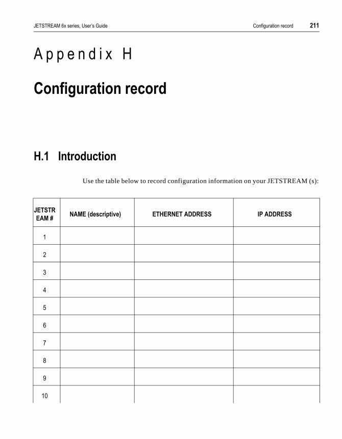
������������� �������� �������� ���%�,� ������ ��� � *$$
(s):
� - - � � � � � E
�!��,� ����!� ��� �
8%$ (!� �������!
Use the table below to record configuration information on your JETSTREAM
������
����H&����<���� ����>�= ��8��&����''���� (���''����
#
0
:
7
)
?
6
>
#&

*$* ���%�,� ������ ��� � ������������� �������� ��������
##
#0
#:
#7
#)
#
#?
#6
#>
0&
������
����H&����<���� ����>�= ��8��&����''���� (���''����

������������� �������� �������� F������" *$+
l.
� - - � � � � � 1
�������#
(%$ (!� �������!
We welcome your comments on this manual.
Please send us your views, by post or fax, to any Specialix office worldwide. (see details in Section D.6 Technical Support). Send it for the attention of Documentation Feedback, c/o Technical Support. Use a photocopy of this page.
Alternatively, you can send us an e-mail, at:
We will endeavour to incorporate your comments in the next edition of this manua
(%* ����!��
'�����!���������������� ���;�5�� ?�������
��,��3�5'�( ��������3�5'�(
�� �, �-����� ���,�+��������+� ��$
��������$
*$. F������" ������������� �������� ��������
'�����!���������������� ���;�5�� ?�������
��,��3�5'�( ��������3�5'�(
�� �, �-����� ���,�+��������+� ��$
��������$
��!��!���%%%
��,��3�5'�( ��������3�5'�(
�� �, �-����� ���,�+��������+� ��$
��������$

��� �������� 1��� �
�Access Restrictions,62ACSII code chart,198–199Add boot host,75, 95add community, 95Add gateway,43, 96Add host,38, 97Add name server,40, 97add trap, 98Adding users,32, 99Address Resolution Protocol (ARP),205admin, 99Admin user,32Alias, 21AUI connector, 6500 model,180Automatic baud rate detection,80
@Baud rate,28Bi-directional modem connections,52, 136Binary to Hex Chart,200Boot file,66, 75–76, 126Boot Hosts,126Boot hosts,75–76BOOTP,70–74BOOTP file, see BOOTPTAB fileBOOTPTAB file,71Broadcast address,21, 113, 126
Cable specifications
6000 model,137–178
6500 model,179–181Centronics interface, see Ports, parallelChange environment,32, 84Change gateway,43Change host,38Change name server,40Change password,34, 83Change terminal setup,84Change user,32Checklist,2, 15CLI commands,93–130CLI, see Command Line InterfaceCommand abbreviation,83Command Line Interface,83Configuration Record,211Connection brackets,2–3Connectors, see PortsConsole,12, 16
'Data bits,28, 84Dedicate line to specific user,28–29Default settings
Lines,12, 25, 30, 108Server,77, 108Users,109
Delete boot host,75, 100delete community, 100Delete gateway,44, 101Delete host,39, 102Delete name server,41, 102delete trap, 101Delete user,34, 103Dialin modem connections,50Dialout modem connections,51Direct (1 to 1) connection
definition and advice,145Direct line type
raw,46, 136rlogin, 135

�� 1��� ��� ��������
telnet,26, 135DNS,204Domain name,20–21, 114, 126Downloadable terminal definitions,66, 66–70
�Emergency Recovery,188Environment,32, 84Error messages,187Extraterms,66–70
�Feedback (on this manual),213Flow control,28, 84
see also Cabling AdviceForms,81FSM, see Full Screen ModeFTP,206Full Screen Mode,81
�Gateway
configuring using bootp,71Gateways,41–44Global replace,29
8Handshaking,84heap, 25, 103Help,83, 104Hex Code Chart,200Hex to Binary Chart,200Host port
on bidirectional connections,52on dialin connections,50
Host Table,38Show host table,124
Hostname,21, 38, 204Hot-keys,91–92Hunt group
Bidirectional modems,52
Dialout modems,51Printers,47, 49Reverse telnet connections,60–61
(Identification Record,211Installation 6000,2–12Installation 6500,15–17Internet address
Definition, 203Internet registration,210Set Internet address,21, 117Show internet address,126
AKill line, 104Kill session,92, 105
6Language,32, 85LANs, 203LEDs,11Line settings,28–29Line types
Bidirectional,46, 52, 136Direct raw,46, 136Direct rlogin,26–28, 135Direct telnet,26–28, 135Normal,25, 135Printer,46, 47–48, 135Reverse raw,46, 49, 136Reverse telnet,46, 60, 136Silent raw,46, 135Silent rlogin,26–28, 135Silent telnet,26–28, 135summary of types,135–136
Logging on,19, 79to remote hosts, see Sessions
Logging out,85, 105from sessions,89

��� �������� 1��� ���
�Main menu,20Menus,81
Command equivalents,94MIB definitions,64, 193–196Modems
Automatic baud rate detection,80Bidirectional,52Dialin, 50Dialiout, 51example connections
direct (1 to 1) connections,157–158structured cabling system,172
Logging on via,80Modem handling,53–59
Modular Terminal AdaptorsInstalling,2–6LEDs,11Technical specification,133Wall-mounting,6
MTS porton bidirectional connections,52on dialin connections,50on reverse telnet connections,60
MTSD, 53–59command options,58–59
&Net reboot,23, 66, 76
see also Set netbootNetwork addressing,203Network configuration,20–22, 37–44Node name, see Server nameNormal line type,25, 135Normal user level,32Nouser,117
7Opto-isolated ports, see RS232 RJ45 ports
�Pages,28–29, 84Parity,28, 84Password
Changing a user’s password,34Changing your own password,83Lost,78Setting a user’s password,32
PCsexample connections
direct (1 to 1) connections,159–160structured cabling systems,173
ping, 106Pin-outs, see Ports, specifications/typesPorts
DB25, see RS232 DB25DB25, see RS422 DB25parallel,176RJ45 10Base T, 6500 model,180RJ45, see RS232 RJ45specifications/types, 6000 model,137–178specifications/types, 6500 model,179–181
Power supply unit,11Predefined sessions,90
for other users,33Print handling (using MTSD),53–59Printer line type,135Printers
parallel, see Ports, parallelserial, see Serial Printers
PrintingUsing MTSD,53Using RCP,47–48
"Quick Start Guide,ix–xii
�RCP,47–48, 207Reboot,76, 107

�> 1��� ��� ��������
see also Net retbootRemote configuration,77Remote printing
Using RCP,47–48Remote printing (using MTSD),53Reset to defaults
Lines,30, 108Server,77, 108Users,109
Restore configuration,77Restricted user level,32Resume session,92Reverse raw,46, 49, 51, 136Reverse telnet,46, 60–61, 136RJ45 10Base T port, 6500 model,180Rlogin,26, 88–89, 111routes, see show routeRS232 DB25
ports female (DCE), 6000 model,139ports male (DTE), 6000 model,140
RS232 RJ45ports, non-shielded, 6000 model,144ports, opto-isolated, 6000 model,177ports, shielded, 6000 model,142
RS232 shielded RJ45ports, 6500 model,181
RS232* (asterisk) DB25ports, 6000 model,141
RS422 DB25ports, 6000 model,178
�Sample terminal definition files,66Save configuration,77screen, 113Screen switch character,91
Changing a user’s screen switch character,33Changing your own screen switch
character,85Security,62, 120see show routeSerial printers,
example connections,
direct (1 to 1) connections,161–164structured cabling system,174
Server configuration,20–22, 126Server name,20, 126Sessions,25, 87–92
see also Predefined sessionsset broadcast, 113set contact, 114set domain, 114set extraterms, 115set gateway, 115set host, 116set internet, 117set line, 117set location, 119set nameserver, 119set netboot, 120Set password,32set security, 120set servername, 121Set sessions,89set subnet, 121set user, 122show gateways, 123show hosts, 124show line, 124show route,126show serverinfo, 126show sessions, 127show start, 129show telnet, 129show user, 128Silent raw,46, 50, 135Silent rlogin,25–28, 135Silent telnet,25–28SNMP,63–64
add community, 95add trap, 98delete community, 100delete trap, 101set contact, 114set location, 119

��� �������� 1��� >
Specialix Private MIB,64, 193–196Stop bits,28, 84Structured Cabling Systems
advice,165–166Subnet mask,21, 121Switch settings,10, 131System administration,65–78
�TCP port number,207TCP/IP,201–210Technical Specifications
6000 and 6001 models,1326500 and 6501 models,134Modular Terminal Adaptor (MTA),133
Technical support,189–191Telnet,26–28, 88–89, 129
direct,25–28, 135reverse,60–61, 136silent,25–28, 135
Term1/2/3,67Terminal definitions,29, 66Terminal servers,201Terminal setup,84Terminal type,29, 66, 84Terminals
example connectionsdirect (1 to 1) connections,147–151structured cabling system,168
Terminals, using the modem device
example connectionsdirect (1 to 1) connections,152–156structured cabling system,170–171
TFTP,66, 67, 207Traps,63Troubleshooting,183–191
5Unix SVR4
dialin under,56Unpaged session,92Upgrading software,66User administration,31–34User level,32User name,32User type, see User level
9Verify installation,23version, 130Video pages,28
Paged sessions,91Virtual circuits,25–28, 45–64
-Wall-mounting,6WANs, 203Wiring, see Cable Specifications