
User’s Manual - Mouser Electronics · User’s Manual 3 Section 1.3.2.1 provides additional...
119
RabbitCore RCM4500W C-Programmable ZigBee Core Module User’s Manual 019–0161 • 090515–G
Transcript of User’s Manual - Mouser Electronics · User’s Manual 3 Section 1.3.2.1 provides additional...

RabbitCore RCM4500WC-Programmable ZigBee Core Module
User’s Manual019–0161 • 090515–G

RabbitCore RCM4500W
Digi International Inc.www.rabbit.com
RabbitCore RCM4500W User’s Manual
Part Number 019-0161 • 090515–G • Printed in U.S.A.©2007–2009 Digi International Inc. • All rights reserved.
Digi International reserves the right to make changes andimprovements to its products without providing notice.
TrademarksRabbit, RabbitCore, and Dynamic C are registered trademarks of Digi International Inc.
ZigBee is a registered trademark of the ZigBee Alliance.Digi is a registered trademark of Digi International Inc.
Rabbit 4000 is a trademark of Digi International Inc.
No part of the contents of this manual may be reproduced or transmitted in any form or by any means without the express written permission of Digi International.
Permission is granted to make one or more copies as long as the copyright page contained therein is included. These copies of the manuals may not be let or sold for any reason without the express written permission of Digi International.
The latest revision of this manual is available on the Rabbit Web site, www.rabbit.com, for free, unregistered download.

User’s Manual
TABLE OF CONTENTS
Chapter 1. Introduction 11.1 RCM4510W Features ...........................................................................................................................21.2 Advantages of the RCM4510W............................................................................................................41.3 Development and Evaluation Tools......................................................................................................5
1.3.1 RCM4510W Development Kit .....................................................................................................51.3.2 Software ........................................................................................................................................6
1.3.2.1 XBee Firmware .................................................................................................................... 61.3.3 Optional Add-Ons .........................................................................................................................71.3.4 Online Documentation ..................................................................................................................7
Chapter 2. Getting Started 92.1 Install Dynamic C .................................................................................................................................92.2 Hardware Connections........................................................................................................................10
2.2.1 Step 1 — Prepare the Prototyping Board for Development........................................................102.2.2 Step 2 — Attach Module to Prototyping Board..........................................................................112.2.3 Step 3 — Connect Programming Cable ......................................................................................122.2.4 Step 4 — Connect Power ............................................................................................................13
2.3 Run a Sample Program .......................................................................................................................142.3.1 Troubleshooting ..........................................................................................................................142.3.2 Run a ZigBee Sample Program...................................................................................................15
2.4 Where Do I Go From Here? ...............................................................................................................162.4.1 Technical Support .......................................................................................................................16
Chapter 3. Running Sample Programs 173.1 Introduction.........................................................................................................................................173.2 Sample Programs ................................................................................................................................18
3.2.1 Serial Communication.................................................................................................................203.2.2 Real-Time Clock .........................................................................................................................233.2.3 ZigBee Sample Programs............................................................................................................23
Chapter 4. Hardware Reference 254.1 RCM4510W Digital Inputs and Outputs ............................................................................................26
4.1.1 Memory I/O Interface .................................................................................................................334.1.2 Other Inputs and Outputs ............................................................................................................334.1.3 Auxiliary I/O ...............................................................................................................................33
4.2 Serial Communication ........................................................................................................................344.2.1 Serial Ports ..................................................................................................................................34
4.2.1.1 Using the Serial Ports......................................................................................................... 354.2.2 Programming Port .......................................................................................................................36
4.3 Programming Cable ............................................................................................................................374.3.1 Changing Between Program Mode and Run Mode ....................................................................374.3.2 Standalone Operation of the RCM4510W ..................................................................................38
4.4 Auxiliary I/O.......................................................................................................................................394.4.1 Digital I/O ...................................................................................................................................394.4.2 A/D Converter.............................................................................................................................404.4.3 Other Pin Features.......................................................................................................................41

RabbitCore RCM4500W
4.5 Other Hardware .................................................................................................................................. 424.5.1 Clock Doubler ............................................................................................................................ 424.5.2 Spectrum Spreader...................................................................................................................... 42
4.6 Memory .............................................................................................................................................. 434.6.1 SRAM......................................................................................................................................... 434.6.2 Flash EPROM............................................................................................................................. 43
Chapter 5. Software Reference 455.1 More About Dynamic C..................................................................................................................... 455.2 Dynamic C Function Calls ................................................................................................................ 47
5.2.1 Digital I/O................................................................................................................................... 475.2.2 Serial Communication Drivers ................................................................................................... 475.2.3 User Block .................................................................................................................................. 475.2.4 SRAM Use.................................................................................................................................. 485.2.5 RCM4510W Cloning.................................................................................................................. 48
5.2.5.1 Including Firmware Update in Cloned Application .......................................................... 495.2.6 ZigBee Drivers ........................................................................................................................... 495.2.7 Prototyping Board Function Calls .............................................................................................. 50
5.2.7.1 Board Initialization ............................................................................................................ 505.2.7.2 Alerts.................................................................................................................................. 51
5.2.8 Auxiliary I/O Pins Function Calls .............................................................................................. 525.2.8.1 Digital I/O.......................................................................................................................... 545.2.8.2 Analog Inputs..................................................................................................................... 55
5.3 Upgrading Dynamic C ....................................................................................................................... 565.3.1 Add-On Modules ........................................................................................................................ 56
Chapter 6. Using the ZigBee Features 576.1 Introduction to the ZigBee Protocol................................................................................................... 57
6.1.1 ZNet vs. ZB Firmware................................................................................................................ 586.2 ZigBee Sample Programs................................................................................................................... 59
6.2.1 Setting Up the Digi XBee USB Coordinator.............................................................................. 596.2.2 Setting up Sample Programs ...................................................................................................... 61
6.3 Using the Sleep Mode ........................................................................................................................ 656.4 Dynamic C Function Calls ................................................................................................................. 676.5 Where Do I Go From Here? ............................................................................................................... 67
Appendix A. RCM4510W Specifications 69A.1 Electrical and Mechanical Characteristics ........................................................................................ 70
A.1.1 XBee RF Module....................................................................................................................... 74A.1.2 Headers ...................................................................................................................................... 75
A.2 Rabbit 4000 DC Characteristics ........................................................................................................ 76A.3 I/O Buffer Sourcing and Sinking Limit............................................................................................. 77A.4 Bus Loading ...................................................................................................................................... 77A.5 Conformal Coating ............................................................................................................................ 80A.6 Jumper Configurations ...................................................................................................................... 81
Appendix B. Prototyping Board 83B.1 Introduction ....................................................................................................................................... 84
B.1.1 Prototyping Board Features ....................................................................................................... 85B.2 Mechanical Dimensions and Layout ................................................................................................. 87B.3 Power Supply..................................................................................................................................... 88B.4 Using the Prototyping Board ............................................................................................................. 89
B.4.1 Adding Other Components ........................................................................................................ 91B.4.2 Measuring Current Draw ........................................................................................................... 91B.4.3 Analog Features ......................................................................................................................... 92B.4.4 Serial Communication ............................................................................................................... 92
B.4.4.1 RS-232 .............................................................................................................................. 92B.5 Prototyping Board Jumper Configurations........................................................................................ 94
User’s Manual
Appendix C. Power Supply 97C.1 Power Supplies...................................................................................................................................97
C.1.1 Battery Backup ...........................................................................................................................97C.1.2 Battery-Backup Circuit...............................................................................................................98C.1.3 Reset Generator ..........................................................................................................................98C.1.4 XBee RF Module Power Supply ................................................................................................99
C.2 Powerdown Mode ..............................................................................................................................99
Appendix D. Additional Configuration Instructions 101D.1 XBee RF Module Firmware Downloads .........................................................................................101
D.1.1 Dynamic C v. 10.44 and Later .................................................................................................101D.1.2 Dynamic C v. 10.21 (RCM4510W preview and standard versions)........................................102D.1.3 Dynamic C v. 10.11 (RCM4510W preview version only) ......................................................103
D.2 Digi® XBee USB Configuration .....................................................................................................104D.2.1 Additional Reference Information ...........................................................................................106D.2.2 Update Digi® XBee USB Firmware........................................................................................106
Index 107
Schematics 111

RabbitCore RCM4500W

User’s Manual 1
1. INTRODUCTION
The RCM4510W next-generation RabbitCore modules add ZigBee®/802.15.4 functionality to the existing Rabbit® 4000 micropro-cessor features to allow you to create a low-cost, low-power,embedded wireless control and communications solution foryour embedded control system. The Rabbit® 4000 microproces-sor features include hardware DMA, clock speeds of up to 60MHz, I/O lines shared with up to six serial ports and four levelsof alternate pin functions that include variable-phase PWM,auxiliary I/O, quadrature decoder, and input capture. Coupledwith more than 500 new opcode instructions that help to reducecode size and improve processing speed, this equates to a coremodule that is fast, efficient, and the ideal solution for a widerange of wireless embedded applications.
The Development Kit has the essentials that you need to designyour own wireless microprocessor-based system, and includes acomplete Dynamic C software development system. This Devel-opment Kit also contains a Prototyping Board that will allowyou to evaluate the RCM4510W modules and to prototype cir-cuits that interface to the RCM4510W modules. You will also beable to write and test software for these modules.
In addition to onboard ZigBee/802.15.4 functionality, the RCM4510W model has a Rabbit 4000 microprocessor operating at 29.49 MHz, static RAM, flash memory, two clocks (main oscillator and timekeeping), and the circuitry necessary for reset and management of battery backup of the Rabbit 4000’s internal real-time clock and the static RAM. One 50-pin header brings out the Rabbit 4000 I/O bus lines, parallel ports, and serial ports. A separate 14-pin auxiliary I/O header brings out up to nine additional I/O pins (up to four of which may be configured as analog inputs) made possible by the onboard XBee RF module.

2 RabbitCore RCM4500W
The RCM4510W receives its +3.3 V power from the customer-supplied motherboard on which it is mounted. The RCM4510W can interface with all kinds of CMOS-compatible digital devices through the motherboard.
1.1 RCM4510W Features• Small size: 1.84" × 2.85" × 0.54"
(47 mm × 72 mm × 14 mm)
• Microprocessor: Rabbit 4000 running at 29.49 MHz
• Up to 40 general-purpose I/O lines configurable with up to four alternate functions
• Up to 9 additional general-purpose I/O lines (up to four of which may be set up as analog inputs) available through the XBee RF module
• 3.3 V I/O lines with low-power modes down to 2 kHz
• Six CMOS-compatible serial ports — four ports are configurable as a clocked serial port (SPI), and two ports are configurable as SDLC/HDLC serial ports.
• Alternate I/O bus can be configured for 8 data lines and 6 address lines (shared with parallel I/O lines)
• 512K flash memory, 512K data SRAM
• Real-time clock
• Watchdog supervisor
Currently there is one production model with a choice of XBee firmware. Table 1 summarizes its main features.
Table 1. RCM4510W Features
Feature RCM4510W
Microprocessor Rabbit® 4000 at 29.49 MHz
Flash Memory 512K
Data SRAM 512K
Serial Ports
6 shared high-speed, CMOS-compatible ports:6 are configurable as asynchronous serial ports;4 are configurable as clocked serial ports (SPI);2 are configurable as SDLC/HDLC serial ports;1 asynchronous serial port is shared with the XBee RF module1 asynchronous serial port is used during programming
XBee RF Module Digi International® XBee® ZB (802.15.4 standard, ISM 2.4 GHz)
XBee FirmwareZNet 2.5 RCM4510W (ZNet) (20-101-1207)
ZigBee PRO RCM4510W (ZB) (20-101-1269)

User’s Manual 3
Section 1.3.2.1 provides additional information about the two types of XBee firmware.
Figure 1. RCM4510W Versions
There are two versions of the RCM4510W model—the standard release, available after April, 2007, is identical in form and function to the preview version. The difference between them is that the RF module is made of discrete onboard components in the preview version, and is included in the pluggable Digi International® XBee® RF module on the standard release. The height of the preview version is also about 0.01” (0.2 mm) less than that of the standard release; Rabbit recommends that you use the dimensions for the standard release specified in this manual in your design. The preview version has not undergone certification testing and is intended for development purposes only. The preview version will no longer be offered once the standard release is available.
NOTE: At the present time the Digi International® XBee® RF modules used with the RCM4510W are not compatible with other XBee® and XBee PRO® RF modules such as those used with Rabbit’s ZigBee®/802.15.4 Application Kit
The RCM4510W is programmed over a standard PC USB port through a programming cable supplied with the Development Kit.
NOTE: The RabbitLink cannot be used to program the RCM4510W or other RabbitCore modules based on the Rabbit 4000 microprocessor.
Appendix A provides detailed specifications for the RCM4510W.

4 RabbitCore RCM4500W
1.2 Advantages of the RCM4510W• Fast time to market using a fully engineered, “ready-to-run/ready-to-program” micro-
processor core.
• Competitive pricing when compared with the alternative of purchasing and assembling individual components.
• Easy C-language program development and debugging
• Rabbit Field Utility to download compiled Dynamic C .bin files, and cloning board options for rapid production loading of programs.
• Generous memory size allows large programs with tens of thousands of lines of code, and substantial data storage.
• Reference application uses a low-cost, low-power ZigBee/802.15.4 infrastructure to connect Rabbit-based devices
• Supports ZigBee/802.15.4 point-to-point, point-to-multipoint, and mesh topologies
• Easily scalable for commercial deployment applications
• RCM4510W can function as a network coordinator, router, or end device

User’s Manual 5
1.3 Development and Evaluation Tools1.3.1 RCM4510W Development Kit
The RCM4510W Development Kit contains the hardware essentials you will need to use the RCM4510W module. The items in the Development Kit and their use are as follows.
• RCM4510W module.
• Prototyping Board.
• Universal AC adapter, 12 V DC, 1 A (includes Canada/Japan/U.S., Australia/N.Z., U.K., and European style plugs). Development Kits sold in North America may contain an AC adapter with only a North American style plug.
• USB programming cable with 10-pin header.
• 10-pin header to DB9 serial cable.
• 14-pin IDC socket connector with bare leads ribbon cable.
• Digi® XBee USB (used as ZigBee coordinator).
• Dynamic C® CD-ROM, with complete product documentation on disk.
• Getting Started instructions.
• A bag of accessory parts for use on the Prototyping Board.
• Rabbit 4000 Processor Easy Reference poster.
• Registration card.
Figure 2. RCM4510W Development Kit
Rabbit and Dynamic C are registered trademarks of Rabbit Semiconductor Inc. Digi is a registered trademark of Digi International Inc.ZigBee is a registered trademark of the ZigBee Alliance.
RabbitCore RCM4510WThe RCM4510W RabbitCore module features built-in ZigBee®/802.15.4 connectivity, allowing you to create a low-cost, low-power, wireless network as part of your control solution for your embedded application. These Getting Started instructions included with the Development Kit will help you get your RCM4510W up and running so that you can run the sample programs to explore its capabilities and develop your own applications.
Development Kit ContentsThe RCM4510W Development Kit contains the following items
• RCM4510W module (with XBee Series 2 ZigBee module installed).
• Prototyping Board.
• Universal AC adapter, 12 V DC, 1 A (includes Canada/Japan/U.S., Australia/N.Z., U.K., and European style plugs).
• USB programming cable with 10-pin header.
• 10-pin header to DB9 serial cable.
• 14-pin IDC socket connector with bare leads ribbon cable.
• Digi® XBee USB (used as ZigBee® coordinator).
• Dynamic C® CD-ROM, with complete product documentation on disk.
• Getting Started instructions.
• Plastic and metal standoffs with 4-40 screws and washers.
• A bag of accessory parts for use on the Prototyping Board.
• Rabbit 4000 Processor Easy Reference poster.
• Registration card.
Visit our online Rabbit store at www.rabbit.com/store/ for the latest information on peripherals and accessories that are available for the RCM4510W RabbitCore modules.
Installing Dynamic C®
Insert the CD from the Development Kit in your PC’s CD-ROM drive. If the installation does not auto-start, run the setup.exe pro-gram in the root directory of the Dynamic C CD. Install any Dynamic C modules after you install Dynamic C.
! !!"#$!
!"%!!!"#$!
&'&
($)$
!**'&
!
"
##
!
!
$
%!"#
"
"
"
"
#
#
#
#
!#&
"
"
"
"
#
#
#
#
!
!
!#&
)+&#,-&
! .! !
'&

6 RabbitCore RCM4500W
1.3.2 Software
The RCM4510W preview version is programmed using version 10.11 or later of Dynamic C, and the standard version requires version 10.21 or later. A compatible version is included on the Development Kit CD-ROM.
Starting with Dynamic C version 10.40, Dynamic C includes the popular µC/OS-II real-time operating system, point-to-point protocol (PPP), FAT file system, RabbitWeb, and other select libraries. Rabbit also offers for purchase the Rabbit Embedded Security Pack featuring the Secure Sockets Layer (SSL) and a specific Advanced Encryption Standard (AES) library.
In addition to the Web-based technical support included at no extra charge, a one-year telephone-based technical support module is also available for purchase. Visit our Web site at www.rabbit.com or contact your Rabbit sales representative or authorized distribu-tor for further information.
1.3.2.1 XBee Firmware
There are two types of XBee firmware available for the RCM4510W — ZNet 2.5 and ZigBee PRO. The firmware preloaded at the factory on your RCM4510W is indicated with the model number and is reflected in different part numbers (see Table 1). A label on the XBee RF module identifies the factory-installed firmware type. Older RCM4510W modules shipped with ZNet firmware and do not have a sticker on their XBee RF module.
• ZNet 2.5 is a networking solution that was developed around an earlier draft of the Zig-Bee standard, and will work only with the MaxStream or Digi International® XBee® RF modules used with the RCM4510W or with the preview version of the RCM4510W. Applications built around ZNet 2.5 may be upgraded to the ZB solution by loading the ZB firmware (standard release RCM4510W RabbitCore modules only) and by recom-piling the application using Dynamic C v. 10.46 or later.
• ZB firmware was developed using the ZigBee PRO feature set and provides the most advanced ZigBee networking capabilities that will interface with any other devices based on the ZigBee PRO standard adopted in 2007.
Dynamic C v. 10.46 and later versions support the ZB firmware with a 64-bit extended PAN ID instead of a 16-bit PAN ID
Rabbit recommends ZB firmware for new customers and new applications.
NOTE: While both ZNet 2.5 and ZB firmware types are technically ZigBee, the protocol layer in them is different and devices with one type of firmware will not function in a network with devices using the other firmware.

User’s Manual 7
1.3.3 Optional Add-Ons
Rabbit has a Mesh Network Add-On Kit available for the RCM4510W.
• Mesh Network Add-On Kit (Part No. 101-1272)
Digi® XBee USB (used as ZigBee coordinator)
Two XBee ZB RF modules
Two RF Interface modules
Digi® XBee USB and serial cables
The XBee ZB RF module is installed on the RF Interface module, which can be con-nected via an RS-232 serial connection to a Windows PC for setup. The Mesh Network Add-On Kit enables you to add additional devices to explore a ZigBee mesh network.
Contact your authorized Rabbit distributor or your sales representative for more informa-tion, or visit our Web site.
1.3.4 Online Documentation
The online documentation is installed along with Dynamic C, and an icon for the docu-mentation menu is placed on the workstation’s desktop. Double-click this icon to reach the menu. If the icon is missing, use your browser to find and load default.htm in the docs folder, found in the Dynamic C installation folder.
The latest versions of all documents are always available for free, unregistered download from our Web sites as well.

8 RabbitCore RCM4500W
User’s Manual 9
2. GETTING STARTED
This chapter describes the RCM4510W hardware in more detail, andexplains how to set up and use the accompanying Prototyping Board.
NOTE: This chapter (and this manual) assume that you have the RCM4510W Develop-ment Kit. If you purchased an RCM4510W module by itself, you will have to adapt the information in this chapter and elsewhere to your test and development setup.
2.1 Install Dynamic CTo develop and debug programs for the RCM4510W modules (and for all other Rabbit hardware), you must install and use Dynamic C.
If you have not yet installed Dynamic C version 10.11 (or a later version), do so now by inserting the Dynamic C CD from the Development Kit in your PC’s CD-ROM drive. If autorun is enabled, the CD installation will begin automatically.
If autorun is disabled or the installation does not start, use the Windows Start | Run menu or Windows Disk Explorer to launch setup.exe from the root folder of the CD-ROM.
The installation program will guide you through the installation process. Most steps of the process are self-explanatory.
Dynamic C uses a COM (serial) port to communicate with the target development system. The installation allows you to choose the COM port that will be used. The default selec-tion is COM1. You may select any available port for Dynamic C’s use. If you are not cer-tain which port is available, select COM1. This selection can be changed later within Dynamic C.
NOTE: The installation utility does not check the selected COM port in any way. Speci-fying a port in use by another device (mouse, modem, etc.) may lead to a message such as "could not open serial port" when Dynamic C is started.
Once your installation is complete, you will have up to three new icons on your PC desk-top. One icon is for Dynamic C, another opens the documentation menu, and the third is for the Rabbit Field Utility, a tool used to download precompiled software to a target system.
If you have purchased any of the optional Dynamic C modules, install them after installing Dynamic C. The modules may be installed in any order. You must install the modules in the same directory where Dynamic C was installed.

10 RabbitCore RCM4500W
2.2 Hardware ConnectionsThere are three steps to connecting the Prototyping Board for use with Dynamic C and the sample programs:
1. Prepare the Prototyping Board for Development.
2. Attach the RCM4510W module to the Prototyping Board.
3. Connect the programming cable between the RCM4510W and the PC.4. Connect the power supply to the Prototyping Board.
2.2.1 Step 1 — Prepare the Prototyping Board for Development
Snap in four of the plastic standoffs supplied in the bag of accessory parts from the Devel-opment Kit in the holes at the corners on the bottom side of the Prototyping Board as shown in Figure 3.
NOTE: Pay attention to use the hole that is pointed out towards the bottom left of the Prototyping Board since the hole below it is used for a standoff when mounting the RCM4510W on the Prototyping Board.
Figure 3. Insert Standoffs
!
"
##
!
!
$
%
!"#
"
"
"
"
#
#
#
#
!#&
"
"
"
"
#
#
#
#
!
!
!#&

User’s Manual 11
2.2.2 Step 2 — Attach Module to Prototyping Board
Turn the RCM4510W module so that the mounting holes line up with the corresponding holes on the Prototyping Board with the programming header at the top right. Insert the metal standoffs as shown in Figure 4, secure them from the bottom using the 4-40 screws and washers, then insert the module’s header J1 on the bottom side into socket RCM1 on the Prototyping Board.
Figure 4. Install the Module on the Prototyping Board
NOTE: It is important that you line up the pins on header J1 of the module exactly with socket RCM1 on the Prototyping Board. The header pins may become bent or damaged if the pin alignment is offset, and the module will not work. Permanent electrical damage to the module may also result if a misaligned module is powered up.
Press the module’s pins gently into the Prototyping Board socket—press down in the area above the header pins. For additional integrity, you may secure the RCM4510W to the standoffs from the top using the remaining three 4-40 screws and washers.
NOTE: If you are using the preview version of the RCM4510W, do not connect the program-ming cable to header J3 (shown below the programming header at right). Header J3 is used only by the factory.
!
"
##
!
!
$
%
!"#
"
"
"
"
#
#
#
#
!#&
"
"
"
"
#
#
#
#
!
!
!
#&
! " ! #$% &$'(
)!$ !&'**!+" ! &'#$% &$'(
#$$&,&'$
- . ! !&'$ / *$$$&
#$$&,&'$

12 RabbitCore RCM4500W
2.2.3 Step 3 — Connect Programming Cable
The programming cable connects the module to the PC running Dynamic C to download programs and to monitor the module during debugging.
Connect the 10-pin connector of the programming cable labeled PROG to header J2 on the RCM4510W as shown in Figure 5. Be sure to orient the marked (usually red) edge of the cable towards pin 1 of the connector. (Do not use the DIAG connector, which is used for a standard serial connection.)
Figure 5. Connect Programming Cable and Power Supply
NOTE: Never disconnect the programming cable by pulling on the ribbon cable. Carefully pull on the connector to remove it from the header.
Connect the other end of the programming cable to an available USB port on your PC or workstation.
Your PC should recognize the new USB hardware, and the LEDs in the shrink-wrapped area of the USB programming cable will flash — if you get an error message, you will have to install USB drivers. Drivers for Windows XP are available in the Dynamic C Drivers\Rabbit USB Programming Cable\WinXP_2K folder — double-click DPInst.exe to install the USB drivers. Drivers for other operating systems are available online at www.ftdichip.com/Drivers/VCP.htm.
!
"
##
!
!
$
%
!"#
"
"
"
"
#
#
#
#
!#&
"
"
"
"
#
#
#
#
!
!
!
#&
#
'()*' +,)- .)*'/012+'/- -34 12-) +,)-
235 5,67 12-) 5,3.'
*'&#
/
),)/'8'87'
)
5)/
-
!**
'&

User’s Manual 13
2.2.4 Step 4 — Connect Power
Once all the other connections have been made, you can connect power to the Prototyping Board.
First, prepare the AC adapter for the country where it will be used by selecting the appro-priate plug. The RCM4510W Development Kit presently includes Canada/Japan/U.S., Australia/N.Z., U.K., and European style plugs. Snap in the top of the plug assembly into the slot at the top of the AC adapter as shown in Figure 5, then press down on the spring-loaded clip below the plug assembly to allow the plug assembly to click into place. Release the clip to secure the plug assembly in the AC adapter.
Connect the AC adapter to 3-pin header J1 on the Prototyping Board as shown in Figure 5. The connector may be attached either way as long as it is not offset to one side—the center pin of J1 is always connected to the positive terminal, and either edge pin is ground.
Plug in the AC adapter. The PWR LED on the Prototyping Board next to the power con-nector at J1 should light up. The RCM4510W and the Prototyping Board are now ready to be used.
NOTE: A RESET button is provided on the Prototyping Board next to the battery holder to allow a hardware reset without disconnecting power.
To power down the Prototyping Board, unplug the power connector from J1. You should disconnect power before making any circuit adjustments in the prototyping area, changing any connections to the board, or removing the RCM4510W from the Prototyping Board.
14 RabbitCore RCM4500W
2.3 Run a Sample ProgramIf you already have Dynamic C installed, you are now ready to test your programming connections by running a sample program. Start Dynamic C by double-clicking on the Dynamic C icon on your desktop or in your Start menu.
You may have to select the COM port assigned to the USB programming cable on your PC. In Dynamic C, select Options > Project Options, then select this COM port on the “Communications” tab. Then check “Use USB to Serial Converter” in “Serial Options.” Click OK to save the settings.
Find the file PONG.C, which is in the Dynamic C SAMPLES folder. To run the program, open it with the File menu, then compile and run it by pressing F9. The STDIO window will open on your PC and will display a small square bouncing around in a box.
2.3.1 Troubleshooting
If you receive the message Could Not Open Serial Port, check that the COM port assigned to the USB programming cable was identified and set up in Dynamic C as described in the preceding section.
If you receive the message No Rabbit Processor Detected, the programming cable may be connected to the wrong COM port, a connection may be faulty, or the target system may not be powered up. First, check to see that the power LED on the Prototyping Board is lit. If the LED is lit, check both ends of the programming cable to ensure that it is firmly plugged into the PC and the programming header on the RCM4510W with the marked (colored) edge of the programming cable towards pin 1 of the programming header. Ensure that the module is firmly and correctly installed in its connectors on the Prototyping Board.
If Dynamic C appears to compile the BIOS successfully, but you then receive a communi-cation error message when you compile and load a sample program, it is possible that your PC cannot handle the higher program-loading baud rate. Try changing the maximum download rate to a slower baud rate as follows.
• Locate the Serial Options dialog on the “Communications” tab in the Dynamic C Options > Project Options menu. Select a slower Max download baud rate.
If a program compiles and loads, but then loses target communication before you can begin debugging, it is possible that your PC cannot handle the default debugging baud rate. Try lowering the debugging baud rate as follows.
• Locate the Serial Options dialog on the “Communications” tab in the Dynamic C Options > Project Options menu. Choose a lower debug baud rate.
Press <Ctrl-Y> to force Dynamic C to recompile the BIOS. You should receive a Bios compiled successfully message once this step is completed successfully.

User’s Manual 15
2.3.2 Run a ZigBee Sample Program
This section explains how to run a sample program in which the RCM4510W is used in its default setup as a router and the Digi® XBee USB is used as the ZigBee coordinator.
1. Connect the Digi® XBee USB acting as a ZigBee coordinator to an available USB port on your PC or workstation. Your PC should recognize the new USB hardware.
2. Find the file AT_INTERACTIVE.C, which is in the Dynamic C SAMPLES\XBee folder. To run the program, open it with the File menu, then compile and run it by pressing F9. The Dynamic C STDIO window will open to display a list of AT commands. Type MENU to redisplay the menu of commands.
Appendix D provides additional configuration information if you experience conflicts while doing development simultaneously with more than one ZigBee coordinator, or if you wish to install new firmware. Different firmware must be installed to use the RCM4510W as either a coordinator or as an end device.
! "#$%""!&"&'&())* !()%)*+$$%",- ./0001! #!&!"111#2!&!"111%"#%"!3#/!3%#%'&'(.4*##!'!##'%5#%5'"" ' $2#'6!'6'
,1%7&(*
6!(!/8*9
:;./<<<<<<(<<<<<<'!/*:;----(----8=>*:;%")%"#)(?*
19

16 RabbitCore RCM4500W
2.4 Where Do I Go From Here?If the sample program ran fine, you are now ready to go on to the sample programs in Chapter 3 and to develop your own applications. The sample programs can be easily modi-fied for your own use. The user's manual also provides complete hardware reference infor-mation and software function calls for the RCM4510W series of modules and the Prototyping Board.
For advanced development topics, refer to the Dynamic C User’s Manual, also in the online documentation set. An Introduction to ZigBee provides background information on the ZigBee protocol, and is available on the CD and on our Web site.
2.4.1 Technical Support
NOTE: If you purchased your RCM4510W through a distributor or through a Rabbit partner, contact the distributor or partner first for technical support.
If there are any problems at this point:
• Use the Dynamic C Help menu to get further assistance with Dynamic C.
• Check the Rabbit Technical Bulletin Board and forums at www.rabbit.com/support/bb/ and at www.rabbitcom/forums/.
• Use the Technical Support e-mail form at www.rabbit.com/support/.

User’s Manual 17
3. RUNNING SAMPLE PROGRAMS
To develop and debug programs for the RCM4510W (and for allother Rabbit hardware), you must install and use Dynamic C.This chapter provides a tour of its major features with respect tothe RCM4510W.
3.1 IntroductionTo help familiarize you with the RCM4510W modules, Dynamic C includes several sam-ple programs. Loading, executing, and studying these programs will give you a solid hands-on overview of the RCM4510W’s capabilities, as well as a quick start with Dynamic C as an application development tool.
This chapter provides sample programs that illustrate the digital I/O and serial capabilities of the RCM4510W RabbitCore module. Section 6.2 discusses the sample programs that illustrate the ZigBee features.
NOTE: The sample programs assume that you have at least an elementary grasp of the C language. If you do not, see the introductory pages of the Dynamic C User’s Manual for a suggested reading list.
In order to run the sample programs discussed in this chapter and elsewhere in this manual,
1. Your module must be plugged in to the Prototyping Board as described in Chapter 2, “Getting Started.”
2. Dynamic C must be installed and running on your PC.
3. The programming cable must connect the programming header on the module to your PC.
4. Power must be applied to the module through the Prototyping Board.
Refer to Chapter 2, “Getting Started,” if you need further information on these steps.
To run a sample program, open it with the File menu, then compile and run it by pressing F9.
Each sample program has comments that describe the purpose and function of the pro-gram. Follow the instructions at the beginning of the sample program.
More complete information on Dynamic C is provided in the Dynamic C User’s Manual.

18 RabbitCore RCM4500W
3.2 Sample ProgramsOf the many sample programs included with Dynamic C, several are specific to the RCM4510W modules. These programs will be found in the SAMPLES\RCM4500W folder.
• CONTROLLED.C—Demonstrates use of the digital outputs by having you turn LEDs DS2 and DS3 on the Prototyping Board on or off from the STDIO window on your PC.
Parallel Port B bit 2 = LED DS2Parallel Port B bit 3 = LED DS3
Once you compile and run CONTROLLED.C, the following display will appear in the Dynamic C STDIO window.
Press “2” or “3” on your keyboard to select LED DS2 or DS3 on the Prototyping Board. Then follow the prompt in the Dynamic C STDIO window to turn the LED ON or OFF. A logic low will light up the LED you selected.
• FLASHLED1.C—demonstrates the use of assembly language to flash LEDs DS2 and DS3 on the Prototyping Board at different rates. Once you have compiled and run this program, LEDs DS2 and DS3 will flash on/off at different rates.
• FLASHLED2.C—demonstrates the use of cofunctions and costatements to flash LEDs DS2 and DS3 on the Prototyping Board at different rates. Once you have compiled and run this program, LEDs DS2 and DS3 will flash on/off at different rates.

User’s Manual 19
• TAMPERDETECTION.C—demonstrates how to detect an attempt to enter the bootstrap mode. When an attempt is detected, the battery-backed onchip-encryption RAM on the Rabbit 4000 is erased. This battery-backed onchip-encryption RAM can be useful to store data such as an AES encryption key from a remote location.
This sample program shows how to load and read the battery-backed onchip-encryption RAM and how to enable a visual indicator.
Once this sample is compiled and running (you pressed the F9 key while the sample program is open), remove the programming cable and press the reset button on the Prototyping Board to reset the module. LEDs DS2 and DS3 will be flashing on and off.
Now press switch S2 to load the battery-backed RAM with the encryption key. The LEDs are now on continuously. Notice that the LEDs will stay on even when you press the reset button on the Prototyping Board.
Reconnect the programming cable briefly and unplug it again to simulate an attempt to access the onchip-encryption RAM. The LEDs will be flashing because the battery-backed onchip-encryption RAM has been erased. Notice that the LEDs will continue flashing even when you press the reset button on the Prototyping Board.
You may press switch S2 again and repeat the last steps to watch the LEDs.
• TOGGLESWITCH.C—demonstrates the use of costatements to detect switch presses using the press-and-release method of debouncing. LEDs DS2 and DS3 on the Proto-typing Board are turned on and off when you press switches S2 and S3. S2 and S3 are controlled by PB4 and PB5 respectively.
Once you have loaded and executed these five programs and have an understanding of how Dynamic C and the RCM4510W modules interact, you can move on and try the other sample programs.

20 RabbitCore RCM4500W
3.2.1 Serial Communication
The following sample programs are found in the SAMPLES\RCM4500W\SERIAL folder.
• FLOWCONTROL.C—This program demonstrates how to configure Serial Port D for CTS/RTS flow control with serial data coming from Serial Port C (TxC) at 115,200 bps. The serial data received are displayed in the STDIO window.
To set up the Prototyping Board, you will need to tie TxD and RxD together on the RS-232 header at J4, and you will also tie TxC and RxC together using the jumpers supplied in the Development Kit as shown in the diagram.
A repeating triangular pattern should print out in the STDIO window. The program will periodically switch flow control on or off to demonstrate the effect of flow control.
If you have two Prototyping Boards with modules, run this sample program on the sending board, then disconnect the programming cable and reset the sending board so that the module is operating in the Run mode. Connect TxC, TxD, and GND on the sending board to RxC, RxD, and GND on the other board, then, with the programming cable attached to the other module, run the sample program.
• PARITY.C—This program demonstrates the use of parity modes by repeatedly sending byte values 0–127 from Serial Port C to Serial Port D. The program will switch between generating parity or not on Serial Port C. Serial Port D will always be checking parity, so parity errors should occur during every other sequence.To set up the Prototyping Board, you will need to tie TxC and RxD together on the RS-232 header at J4 using one of the jumpers supplied in the Development Kit as shown in the diagram.The Dynamic C STDIO window will display the error sequence.
• SERDMA.C—This program demonstrates using DMA to transfer data from a circular buffer to the serial port and vice versa. The Dynamic C STDIO window is used to view or clear the buffer.Before you compile and run the sample program, you will need to connect the RS-232 header at J4 to your PC as shown in the diagram using the serial to DB9 cable supplied in the Development Kit.
Once you have compiled and run the sample program, start Tera Term or another terminal emulation program to connect to the selected PC serial port at a baud rate of 115,200 bps. You can observe the output in the Dynamic C STDIO window as you type in Tera Term, and you can also use the Dynamic C STDIO window to clear the buffer.
The Tera Term utility can be downloaded from hp.vector.co.jp/authors/VA002416/teraterm.html.
/9 9
9 9
/9
99
9
/
9
9
9
9
),)/'8'87'

User’s Manual 21
• SIMPLE3WIRE.C—This program demonstrates basic RS-232 serial communication. Lower case characters are sent on TxC, and are received by RxD. The received characters are converted to upper case and are sent out on TxD, are received on RxC, and are displayed in the Dynamic C STDIO window.
To set up the Prototyping Board, you will need to tie TxD and RxC together on the RS-232 header at J4, and you will also tie RxD and TxC together using the jumpers supplied in the Development Kit as shown in the diagram.
• SIMPLE5WIRE.C—This program demonstrates 5-wire RS-232 serial communication with flow control on Serial Port D and data flow on Serial Port C.
To set up the Prototyping Board, you will need to tie TxD and RxD together on the RS-232 header at J4, and you will also tie TxC and RxC together using the jumpers supplied in the Development Kit as shown in the diagram.
Once you have compiled and run this program, you can test flow con-trol by disconnecting the TxD jumper from RxD while the program is running. Charac-ters will no longer appear in the STDIO window, and will display again once TxD is connected back to RxD.
If you have two Prototyping Boards with modules, run this sample program on the sending board, then disconnect the programming cable and reset the sending board so that the module is operating in the Run mode. Connect TxC, TxD, and GND on the sending board to RxC, RxD, and GND on the other board, then, with the programming cable attached to the other module, run the sample program. Once you have compiled and run this program, you can test flow control by disconnecting TxD from RxD as before while the program is running. Since the J4 header locations on the two Prototyping Boards are connected with wires, there are no slip-on jumpers at J4 on either Prototyping Board.
• SWITCHCHAR.C—This program demonstrates transmitting and then receiving an ASCII string on Serial Ports C and D. It also displays the serial data received from both ports in the STDIO window.
To set up the Prototyping Board, you will need to tie TxD and RxC together on the RS-232 header at J4, and you will also tie RxD and TxC together using the jumpers supplied in the Development Kit as shown in the diagram.
Once you have compiled and run this program, press and release switches S2 and S3 on the Prototyping Board. The data sent between the serial ports will be displayed in the STDIO window.
/9 9
9 9
/9 9
9 9
/9 9
9 9

22 RabbitCore RCM4500W
• IOCONFIG_SWITCHECHO.C—This program demonstrates how to set up Serial Ports E and F, which then transmit and then receive an ASCII string when switch S2 or S3 is pressed. The echoed serial data are displayed in the Dynamic C STDIO window.
Note that the I/O lines that carry the Serial Port E and F signals are not the Rabbit 4000 defaults. The Serial Port E and F I/O lines are configured by calling the library function serEFconfig() that was generated by the Rabbit 4000 IOCONFIG.EXE utility program.
Note that the RCM45_29MHZ_IOCONFIG.LIB library generated by IOCONFIG.EXE to support this sample program is provided in the Dynamic C SAMPLES\RCM4500W\SERIAL folder.
Serial Port E is configured to use Parallel Port E bits PE6 and PE7. These signals are available on the Prototyping Board's Module Extension Header (header J2).
Serial Port F is configured to use Parallel Port C bits PC2 and PC3. These signals are available on the Prototyping Board's RS-232 connector (header J4).
Serial Port D is left in its default configuration, using Parallel Port C bits PC0 and PC1. These signals are available on the Prototyping Board's RS-232 connector (header J4). Serial Port D transmits and then receives an ASCII string with Serial Port F when switch S3 is pressed.
To set up the Prototyping Board, you will need to tie TxC and RxD together on the RS-232 header at J4 using the jumpers supplied in the Development Kit; you will also tie TxE (PE6) and RxE (PE7) together with a soldered wire or with a wire jumper if you have soldered in the IDC header supplied with the accessory parts in the Development Kit.Once you have compiled and run this program, press and release switches S2 or S3 on the Prototyping Board. The data echoed between the serial ports will be displayed in the STDIO window.
/
9
99 9
/0 !
$
##
!#&
# !

User’s Manual 23
3.2.2 Real-Time Clock
If you plan to use the real-time clock functionality in your application, you will need to set the real-time clock. Use the SETRTCKB.C sample program from the Dynamic C SAMPLES\RTCLOCK folder, and follow the onscreen prompts. The RTC_TEST.C sample program in the Dynamic C SAMPLES\RTCLOCK folder provides additional examples of how to read and set the real-time clock.
3.2.3 ZigBee Sample Programs
Section 6.2 describes the sample programs associated with the XBee RF module.

24 RabbitCore RCM4500W

User’s Manual 25
4. HARDWARE REFERENCE
Chapter 4 describes the hardware components and principal hardwaresubsystems of the RCM4510W. Appendix A, “RCM4510W Specifica-tions,” provides complete physical and electrical specifications.
Figure 6 shows the Rabbit-based subsystems designed into the RCM4510W.
Figure 6. RCM4510W Subsystems
0,1!2
''!!&
$$1
2&+&&
345 34!$& 22&
'$6$! $+&$'
!$4!2*2& 2&!
6 26$$
37
( ,1!2
8 &!
' "79. 6$$
&' )9:

26 RabbitCore RCM4500W
4.1 RCM4510W Digital Inputs and OutputsFigure 7 shows the RCM4510W pinouts for headers J1 and J4.
Figure 7. RCM4510W Pinout
Headers J1 is a standard 2 × 25 IDC header with a nominal 1.27 mm pitch, and header J4 is a standard 2 × 7 IDC header with a nominal 2 mm pitch.
!3 $!!*
!$##$
%!"$#
" :"""
9
##
###
!#&
##$" :""" 9##### !#
/ /
2.
$%$
!#& !2.
2. ; 2)- .)22'.-'8

User’s Manual 27
Figure 8 shows the use of the Rabbit 4000 microprocessor ports in the RCM4510W modules.
Figure 8. Use of Rabbit 4000 Ports
The ports on the Rabbit 4000 microprocessor used in the RCM4510W are configurable, and so the factory defaults can be reconfigured. Table 2 lists the Rabbit 4000 factory defaults and the alternate configurations.
$$1
#$ 7 #$ #$ . %
#$ ;
< ""<"
#<#
<
&2' <$!
20 .+ $3 &6 #$
& 4< 20
7 &20 &$%3$ 8 &!
!2( )9:
0 9
0 9<
#$ 3$& #$! = .
#$$&#$
3$& #$ 7
> '3$& #$
"0 0
0
0
3$& #$! ; = 8
##$0%
#$
0 #0#0 #

28 RabbitCore RCM4500W
Table 2. RCM4510W Pinout Configurations
Pin Pin Name Default Use Alternate Use NotesH
eade
r J1
1 +3.3 V_IN
2 GND
3 /RES_OUT Reset output Reset inputReset output from Reset Generator or external reset input
4 /IORD Output External I/O read strobe
5 /IOWR Output External I/O write strobe
6 /RESET_IN Input Input to Reset Generator
7 VBAT_EXT Battery input
8–15 PA[0:7] Input/Output
Slave port data bus(SD0–SD7)
External I/O data bus(ID0–ID7)
16 PB0 Input/OutputSCLKExternal I/O Address IA6
SCLKB (reserved for future use)
17 PB1 Input/OutputSCLKAExternal I/O Address IA7
Programming port CLKA
18 PB2 Input/Output/SWRExternal I/O Address IA0
19 PB3 Input/Output/SRDExternal I/O Address IA1
20 PB4 Input/OutputSA0External I/O Address IA2
21 PB5 Input/OutputSA1External I/O Address IA3
22 PB6 Input/Output/SCSExternal I/O Address IA4
23 PB7 Input/Output/SLAVATNExternal I/O Address IA5

User’s Manual 29
Hea
der J
1
24 PC0 Input/Output
TXDI/O Strobe I0Timer C0TCLKF
Serial Port D
25 PC1 Input/Output
RXD/TXDI/O Strobe I1Timer C1RCLKFInput Capture
26 PC2 Input/OutputTXC/TXFI/O Strobe I2Timer C2
Serial Port C
27 PC3 Input/Output
RXC/TXC/RXFI/O Strobe I3Timer C3SCLKDInput Capture
28 PC4 Input/Output
TXBI/O Strobe I4PWM0TCLKE
Serial Port B (shared by XBee RF module)
29 PC5 Input/Output
RXB/TXBI/O Strobe I5PWM1RCLKEInput Capture
30 PC6 Input/OutputTXA/TXEI/O Strobe I6PWM2
Programming port
31 PC7 Input/Output
RXA/TXA/RXEI/O Strobe I7PWM3SCLKCInput Capture
32 PE0 Input/Output
I/O Strobe I0A20Timer C0TCLKFINT0QRD1B
Table 2. RCM4510W Pinout Configurations (continued)
Pin Pin Name Default Use Alternate Use Notes

30 RabbitCore RCM4500W
Hea
der J
1
33 PE1 Input/Output
I/O Strobe I1A21Timer C1RXD/RCLKFINT1QRD1AInput Capture
34 PE2 Input/Output
I/O Strobe I2A22Timer C2TXFDREQ0QRD2B
35 PE3 Input/Output
I/O Strobe I3A23Timer C3RXC/RXF/SCLKDDREQ1QRD2AInput Capture
36 PE4 Input/Output
I/O Strobe I4/A0INT0PWM0TCLKE
37 PE5/SMODE0 Input/Output
I/O Strobe I5INT1PWM1RXB/RCLKEInput Capture
PE5 is the default configuration
38 PE6/SMODE1 Input/Output
I/O Strobe I6PWM2TXEDREQ0
PE6 is the default configuration
39 PE7/STATUS Input/Output
I/O Strobe I7PWM3RXA/RXE/SCLKCDREQ1Input Capture
PE7 is the default configuration
Table 2. RCM4510W Pinout Configurations (continued)
Pin Pin Name Default Use Alternate Use Notes

User’s Manual 31
Hea
der J
1
40 PD0 Input/Output
I/O Strobe I0Timer C0D8INT0SCLKD/TCLKFQRD1B
RCM4510W only
41 PD1 Input/Output
IA6I/O Strobe I1Timer C1D9INT1RXD/RCLKFQRD1AInput Capture
42 PD2 Input/Output
I/O Strobe I2Timer C2D10DREQ0TXF/SCLKCQRD2B
43 PD3 Input/Output
IA7I/O Strobe I3Timer C3D11DREQ1RXC/RXFQRD2AInput Capture
44 PD4 Input/Output
I/O Strobe I4D12PWM0TXB/TCLKE
45 PD5 Input/Output
IA6I/O Strobe I5D13PWM1RXB/RCLKEInput Capture
Table 2. RCM4510W Pinout Configurations (continued)
Pin Pin Name Default Use Alternate Use Notes

32 RabbitCore RCM4500W
Hea
der J
1
46 PD6 Input/Output
I/O Strobe I6D14PWM2TXA/TXE
Serial Port E (RCM4510W only)
47 PD7 Input/Output
IA7I/O Strobe I7D15PWM3RXA/RXEInput Capture
48 CONVERT Analog InputReserved for future use
49 VREF Analog reference voltage
50 GND Ground Ground
Hea
der J
4
1 ADC0/DIO0 Input/Output Analog Input Software-selectable
2 ADC1/DIO1 Input/Output Analog Input Software-selectable
3 ADC2/DIO2 Input/Output Analog Input Software-selectable
4 ADC3/DIO3 Input/Output Analog Input Software-selectable
5 GND Ground
6 GPIO8/VREF Input/Output Analog reference voltage (1.2 V)
Software-selectable, analog ref. voltage not presently supported
7 n.c.
8 +3.3 V
9 SYS_PWR_ON Output
Used by XBee RF module to place or remove remaining RCM4510W circuitry in “sleep” mode
10 GPIO0 Input/Output
11 GPIO13 Input/Output
12 n.c.
13 GPIO15 Input/Output
14 GPIO16 Input/Output
Table 2. RCM4510W Pinout Configurations (continued)
Pin Pin Name Default Use Alternate Use Notes

User’s Manual 33
4.1.1 Memory I/O Interface
The Rabbit 4000 address lines (A0–A19) and all the data lines (D0–D7) are routed inter-nally to the onboard flash memory and SRAM chips. I/0 write (/IOWR) and I/0 read (/IORD) are available for interfacing to external devices, and are also used by the RCM4510W.
Parallel Port A can also be used as an external I/O data bus to isolate external I/O from the main data bus. Parallel Port B pins PB2–PB7 can also be used as an auxiliary address bus.
When using the external I/O bus for any reason, you must add the following line at the beginning of your program.
#define PORTA_AUX_IO // required to enable external I/O bus
Selected pins on Parallel Ports D and E as specified in Table 2 may be used for input capture, quadrature decoder, DMA, and pulse-width modulator purposes.
4.1.2 Other Inputs and Outputs
The STATUS and the two SMODE pins, SMODE0 and SMODE1, can be brought out to header J1 instead of the PE5–PE7 pins as explained in Appendix A.6.
/RESET_IN is normally associated with the programming port, but may be used as an external input to reset the Rabbit 4000 microprocessor and the RCM4510W memory. /RESET_OUT is an output from the reset circuitry that can be used to reset other peripheral devices.
4.1.3 Auxiliary I/O
Up to nine additional digital I/O, up to four of which may be configured in software as analog inputs, a +3.3 V DC power supply point and ground, and a SYS_PWR_ON line are brought out on auxiliary I/O header J4. Section 4.4 describes the use of these lines in more detail.

34 RabbitCore RCM4500W
4.2 Serial CommunicationThe RCM4510W module does not have any serial driver or receiver chips directly on the board. However, a serial interface may be incorporated on the board the RCM4510W is mounted on. For example, the Prototyping Board has an RS-232 transceiver chip.
4.2.1 Serial Ports
There are six serial ports designated as Serial Ports A, B, C, D, E, and F. All six serial ports can operate in an asynchronous mode up to the baud rate of the system clock divided by 8. An asynchronous port can handle 7 or 8 data bits. A 9th bit address scheme, where an additional bit is sent to mark the first byte of a message, is also supported.
Serial Port A is normally used as a programming port, but may be used either as an asyn-chronous or as a clocked serial port once application development has been completed and the RCM4510W is operating in the Run Mode.
Serial Port B is shared with the RCM4510W module’s asynchronous XBee RF module. Flow control for the XBee RF module is provided from the Rabbit 4000 RxD+ and TxD– Ethernet pins.
Serial Ports C and D can also be operated in the clocked serial mode. In this mode, a clock line synchronously clocks the data in or out. Either of the two communicating devices can supply the clock. Note that PD2 and PD0 provide the SCLKC and SCLKD outputs auto-matically when Serial Ports C and D are set up as clocked serial ports.
Serial Ports E and F can also be configured as SDLC/HDLC serial ports. The IrDA proto-col is also supported in SDLC format by these two ports. Serial Ports E and F must be con-figured before they can be used. The sample program IOCONFIG_SWITCHECHO.C in the Dynamic C SAMPLES\RCM4500W\SERIAL folder shows how to configure Serial Ports E and F.
User’s Manual 35
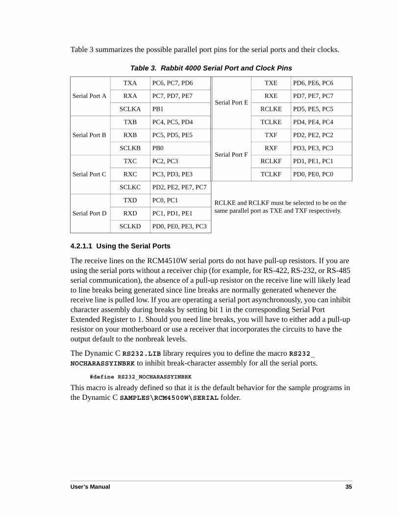
Table 3 summarizes the possible parallel port pins for the serial ports and their clocks.
4.2.1.1 Using the Serial Ports
The receive lines on the RCM4510W serial ports do not have pull-up resistors. If you are using the serial ports without a receiver chip (for example, for RS-422, RS-232, or RS-485 serial communication), the absence of a pull-up resistor on the receive line will likely lead to line breaks being generated since line breaks are normally generated whenever the receive line is pulled low. If you are operating a serial port asynchronously, you can inhibit character assembly during breaks by setting bit 1 in the corresponding Serial Port Extended Register to 1. Should you need line breaks, you will have to either add a pull-up resistor on your motherboard or use a receiver that incorporates the circuits to have the output default to the nonbreak levels.
The Dynamic C RS232.LIB library requires you to define the macro RS232_NOCHARASSYINBRK to inhibit break-character assembly for all the serial ports.
#define RS232_NOCHARASSYINBRK
This macro is already defined so that it is the default behavior for the sample programs in the Dynamic C SAMPLES\RCM4500W\SERIAL folder.
Table 3. Rabbit 4000 Serial Port and Clock Pins
Serial Port A
TXA PC6, PC7, PD6
Serial Port E
TXE PD6, PE6, PC6
RXA PC7, PD7, PE7 RXE PD7, PE7, PC7
SCLKA PB1 RCLKE PD5, PE5, PC5
Serial Port B
TXB PC4, PC5, PD4 TCLKE PD4, PE4, PC4
RXB PC5, PD5, PE5
Serial Port F
TXF PD2, PE2, PC2
SCLKB PB0 RXF PD3, PE3, PC3
Serial Port C
TXC PC2, PC3 RCLKF PD1, PE1, PC1
RXC PC3, PD3, PE3 TCLKF PD0, PE0, PC0
SCLKC PD2, PE2, PE7, PC7
RCLKE and RCLKF must be selected to be on the same parallel port as TXE and TXF respectively.Serial Port D
TXD PC0, PC1
RXD PC1, PD1, PE1
SCLKD PD0, PE0, PE3, PC3
36 RabbitCore RCM4500W
4.2.2 Programming Port
The RCM4510W is programmed via the 10-pin header labeled J2. The programming port uses the Rabbit 4000’s Serial Port A for communication. Dynamic C uses the programming port to download and debug programs.
Serial Port A is also used for the following operations.
• Cold-boot the Rabbit 4000 on the RCM4510W after a reset.
• Fast copy designated portions of flash memory from one Rabbit-based board (the master) to another (the slave) using the Rabbit Cloning Board.
Alternate Uses of the Programming Port
All three Serial Port A signals are available as
• a synchronous serial port
• an asynchronous serial port, with the clock line usable as a general CMOS I/O pin
The programming port may also be used as a serial port via the DIAG connector on the programming cable.
In addition to Serial Port A, the Rabbit 4000 startup-mode (SMODE0, SMODE1), STATUS, and reset pins are available on the programming port.
The two startup-mode pins determine what happens after a reset—the Rabbit 4000 is either cold-booted or the program begins executing at address 0x0000.
The status pin is used by Dynamic C to determine whether a Rabbit microprocessor is present. The status output has three different programmable functions:
1. It can be driven low on the first op code fetch cycle.
2. It can be driven low during an interrupt acknowledge cycle.
3. It can also serve as a general-purpose output once a program has been downloaded and is running.
The reset pin is an external input that is used to reset the Rabbit 4000.
Refer to the Rabbit 4000 Microprocessor User’s Manual for more information.
User’s Manual 37
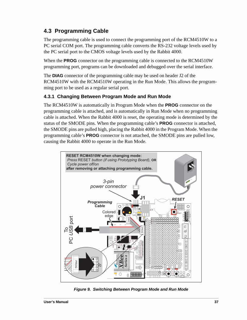
4.3 Programming CableThe programming cable is used to connect the programming port of the RCM4510W to a PC serial COM port. The programming cable converts the RS-232 voltage levels used by the PC serial port to the CMOS voltage levels used by the Rabbit 4000.
When the PROG connector on the programming cable is connected to the RCM4510W programming port, programs can be downloaded and debugged over the serial interface.
The DIAG connector of the programming cable may be used on header J2 of the RCM4510W with the RCM4510W operating in the Run Mode. This allows the program-ming port to be used as a regular serial port.
4.3.1 Changing Between Program Mode and Run Mode
The RCM4510W is automatically in Program Mode when the PROG connector on the programming cable is attached, and is automatically in Run Mode when no programming cable is attached. When the Rabbit 4000 is reset, the operating mode is determined by the status of the SMODE pins. When the programming cable’s PROG connector is attached, the SMODE pins are pulled high, placing the Rabbit 4000 in the Program Mode. When the programming cable’s PROG connector is not attached, the SMODE pins are pulled low, causing the Rabbit 4000 to operate in the Run Mode.
Figure 9. Switching Between Program Mode and Run Mode
!
"
##
!
!
$
%
!"#
"
"
"
"
#
#
#
#
!#&
"
"
"
"
#
#
#
#
!
!
!
#&
/
;3;< " 2& '?## :!"&*$ $6 $ &&2 $$& 2&+ (
),)/'8'87'
)
5)/
-
!**'&

38 RabbitCore RCM4500W
A program “runs” in either mode, but can only be downloaded and debugged when the RCM4510W is in the Program Mode.
Refer to the Rabbit 4000 Microprocessor User’s Manual for more information on the pro-gramming port.
4.3.2 Standalone Operation of the RCM4510W
Once the RCM4510W has been programmed successfully, remove the programming cable from the programming connector and reset the RCM4510W. The RCM4510W may be reset by cycling, the power off/on or by pressing the RESET button on the Prototyping Board. The RCM4510W module may now be removed from the Prototyping Board for end-use installation.
CAUTION: Power to the Prototyping Board or other boards should be disconnected when removing or installing your RCM4510W module to protect against inadvertent shorts across the pins or damage to the RCM4510W if the pins are not plugged in cor-rectly. Do not reapply power until you have verified that the RCM4510W module is plugged in correctly.

User’s Manual 39
4.4 Auxiliary I/O4.4.1 Digital I/O
The RCM4510W modules’ XBee RF module has up to five general-purpose I/O on header J4 — GPIO0, GPIO8, GPIO13, GPIO15, and GPIO16. Table 4 provides the names used in Dynamic C for these pins and their default configurations.
All the pins have the following software-configurable features.
• Selectable as input or output.
• Output is either sinking or sourcing, and may be set up for a default high or low.
• Can be pulled up internally.
The four digital I/O, DIO0–DIO3, are similar to the general-purpose I/O, but may instead by configured in software as analog inputs.
NOTE: The XBee firmware associated with Dynamic C v. 10.46 does not support I/O reads for RCM4510W RabbitCore modules set up as API coordinators or as API routers.
The input switching threshold between logic 0 and logic 1 is 0.66–2.64 V DC, and the out-put switching threshold between logic 0 and logic 1 is 0.59–2.71 V DC.
Table 4. XBee RF Module GPIO Pin Setup
J4 Pin Schematic Name Dynamic C Name Default Configuration
10 GPIO0 DIO_05 Digital Output (high)
6 GPIO8 DIO_12 Digital Input (pulled up)
11 GPIO13 DIO_04 Digital Output (high)
13 GPIO15 DIO_10 Digital Output (high)
14 GPIO16 DIO_11 Digital Input (pulled up)

40 RabbitCore RCM4500W
4.4.2 A/D Converter
The RCM4510W modules’ XBee RF module has four inputs on header J4 that may be set up in software as analog inputs.
The four analog input pins, ADC0–ADC3, each have an input impedance of 6–7 MΩ, depending on whether they are used as single-ended or differential inputs. The input signal can range from -1.2 V to +1.2 V (differential mode) or from 0 V to +1.2 V (single-ended mode).
Use a resistor divider such as the one shown in Figure 10 to measure voltages above 1.2 V on the analog inputs.
Figure 10. Resistor Divider Network for Analog Inputs
The R1 resistors are typically 20 kΩ to 100 kΩ, with a lower resistance leading to more accuracy, but at the expense of a higher current draw. The R0 resistors would then be 180 kΩ to 900 kΩ for a 10:1 attenuator. The capacitor filters noise pulses on the A/D converter input.
The A/D converter can only accept positive voltages. With the R1 resistors connected to ground, your analog circuit is well-suited to perform positive A/D conversions. When the R1 resistors are tied to ground for differential measurements, both differential inputs must be referenced to analog ground, and both inputs must be positive with respect to analog ground.
!#&
4
5$*!*6

User’s Manual 41
If a device such as a battery is connected across two channels for a differential measurement, and it is not referenced to analog ground, then the current from the device will flow through both sets of attenuator resistors without flowing back to analog ground as shown in Figure 11. This will generate a negative voltage at one of the inputs, ADC1, which will almost certainly lead to inaccurate A/D conversions. To make such differential measurements, connect the R1 resistors to the A/D converter’s internal reference voltage, which is 1.2 V. This internal reference voltage can be configured in software to be available on pin 6 of header J4 as VREF, and allows you to convert analog input voltages that are negative with respect to analog ground.
NOTE: This software configuration option for VREF and differential measurements are not supported at this time.
NOTE: The amplifier inside the A/D converter’s internal voltage reference circuit has a very limited output-current capability. The internal buffer can source up to 20 mA and sink only up to 20 µA. Use a separate buffer amplifier if you need to supply any load current.
4.4.3 Other Pin Features
There are two other features brought out on the auxiliary I/O header J4.
• There is a +3.3 V power supply point on pin 8, which can deliver up to 25 mA at 3.3 V DC. This power supply point is essentially a filtered and isolated version of the regu-lated +3.3 V DC power that is supplied to the RCM4510W RabbitCore module through pin 1 of header J1 from the motherboard.
• The SYS_PWR_ON signal on pin 9 is used by the XBee RF module to place the remaining circuitry on the RCM4510W RabbitCore module into a powered-down “sleep” mode or to bring it back up to normal operation.
Figure 11. Current Flow from Ungroundedor Floating Source
2&
2&
<
=
#$
42 RabbitCore RCM4500W
4.5 Other Hardware4.5.1 Clock Doubler
The clock doubler on the RCM4510W is disabled by default.
4.5.2 Spectrum Spreader
The Rabbit 4000 features a spectrum spreader, which helps to mitigate EMI problems. The spectrum spreader is on by default, but it may also be turned off or set to a stronger setting. The means for doing so is through a simple configuration macro as shown below.
NOTE: Refer to the Rabbit 4000 Microprocessor User’s Manual for more information on the spectrum-spreading setting and the maximum clock speed.
1. Select the “Defines” tab from the Dynamic C Options > Project Options menu.
2. Normal spreading is the default, and usually no entry is needed. If you need to specify normal spreading, add the line
ENABLE_SPREADER=1
For strong spreading, add the lineENABLE_SPREADER=2
To disable the spectrum spreader, add the lineENABLE_SPREADER=0
NOTE: The strong spectrum-spreading setting is not recommended since it may limit the maximum clock speed or the maximum baud rate. It is unlikely that the strong set-ting will be used in a real application.
3. Click OK to save the macro. The spectrum spreader will be set according to the macro value whenever a program is compiled using this project file.

User’s Manual 43
4.6 Memory4.6.1 SRAM
All RCM4510W modules have 512K of battery-backed data SRAM installed at U4.
4.6.2 Flash EPROM
All RCM4510W modules also have 512K of flash EPROM installed at U3.
NOTE: Rabbit recommends that any customer applications should not be constrained by the sector size of the flash EPROM since it may be necessary to change the sector size in the future.
Writing to arbitrary flash memory addresses at run time is discouraged. Instead, define a “user block” area to store persistent data. The functions writeUserBlock and readUserBlock are provided for this. Refer to the Rabbit 4000 Microprocessor Designer’s Handbook for additional information.

44 RabbitCore RCM4500W

User’s Manual 45
5. SOFTWARE REFERENCE
Dynamic C is an integrated development system for writingembedded software. It runs on an IBM-compatible PC and isdesigned for use with single-board computers and other devicesbased on the Rabbit microprocessor. Chapter 5 describes thelibraries and function calls related to the RCM4510W.
5.1 More About Dynamic CDynamic C has been in use worldwide since 1989. It is specially designed for program-ming embedded systems, and features quick compile and interactive debugging. A com-plete reference guide to Dynamic C is contained in the Dynamic C User’s Manual.
You have a choice of doing your software development in the flash memory or in the static SRAM included on the RCM4510W. The flash memory and SRAM options are selected with the Options > Program Options > Compiler menu.
The advantage of working in RAM is to save wear on the flash memory, which is limited to about 100,000 write cycles. The disadvantage is that the code and data might not both fit in RAM.
NOTE: Do not depend on the flash memory sector size or type in your program logic. The RCM4510W and Dynamic C were designed to accommodate flash devices with various sector sizes in response to the volatility of the flash-memory market.
Developing software with Dynamic C is simple. Users can write, compile, and test C and assembly code without leaving the Dynamic C development environment. Debugging occurs while the application runs on the target. Alternatively, users can compile a program to an image file for later loading. Dynamic C runs on PCs under Windows NT and later—see Rabbit’s Technical Note TN257, Running Dynamic C® With Windows Vista®, for additional information if you are using a Dynamic C under Windows Vista. Programs can be downloaded at baud rates of up to 460,800 bps after the program compiles.

46 RabbitCore RCM4500W
Dynamic C has a number of standard features.
• Full-feature source and/or assembly-level debugger, no in-circuit emulator required.
• Royalty-free TCP/IP stack with source code and most common protocols.
• Hundreds of functions in source-code libraries and sample programs:Exceptionally fast support for floating-point arithmetic and transcendental functions.
RS-232 and RS-485 serial communication.
Analog and digital I/O drivers.
I2C, SPI, GPS, file system.
LCD display and keypad drivers.
• Powerful language extensions for cooperative or preemptive multitasking
• Loader utility program to load binary images into Rabbit targets in the absence of Dynamic C.
• Provision for customers to create their own source code libraries and augment on-line help by creating “function description” block comments using a special format for library functions.
• Standard debugging features:Breakpoints—Set breakpoints that can disable interrupts.
Single-stepping—Step into or over functions at a source or machine code level, µC/OS-II aware.
Code disassembly—The disassembly window displays addresses, opcodes, mnemonics, and machine cycle times. Switch between debugging at machine-code level and source-code level by simply opening or closing the disassembly window.
Watch expressions—Watch expressions are compiled when defined, so complex expressions including function calls may be placed into watch expressions. Watch expressions can be updated with or without stopping program execution.
Register window—All processor registers and flags are displayed. The contents of general registers may be modified in the window by the user.
Stack window—shows the contents of the top of the stack.
Hex memory dump—displays the contents of memory at any address.
STDIO window—printf outputs to this window and keyboard input on the host PC can be detected for debugging purposes. printf output may also be sent to a serial port or file.

User’s Manual 47
5.2 Dynamic C Function Calls5.2.1 Digital I/O
The RCM4510W was designed to interface with other systems, and so there are no drivers written specifically for the Rabbit 4000 I/O. The general Dynamic C read and write func-tions allow you to customize the parallel I/O to meet your specific needs. For example, use
WrPortI(PEDDR, &PEDDRShadow, 0x00);
to set all the Port E bits as inputs, or useWrPortI(PEDDR, &PEDDRShadow, 0xFF);
to set all the Port E bits as outputs.
When using the external I/O bus on the Rabbit 4000 chip, add the line#define PORTA_AUX_IO // required to enable external I/O bus
to the beginning of any programs using the external I/O bus.
The sample programs in the Dynamic C SAMPLES/RCM4500W folder provide further examples.
5.2.2 Serial Communication Drivers
Library files included with Dynamic C provide a full range of serial communications sup-port. The RS232.LIB library provides a set of circular-buffer-based serial functions. The PACKET.LIB library provides packet-based serial functions where packets can be delimited by the 9th bit, by transmission gaps, or with user-defined special characters. Both libraries provide blocking functions, which do not return until they are finished transmitting or receiving, and nonblocking functions, which must be called repeatedly until they are fin-ished, allowing other functions to be performed between calls. For more information, see the Dynamic C Function Reference Manual and Technical Note TN213, Rabbit Serial Port Software.
5.2.3 User Block
Certain function calls involve reading and storing calibration constants from/to the simulated EEPROM in flash memory located at the top 2K of the reserved user block memory area (3800–39FF). This leaves the address range 0–37FF in the user block available for your application.
These address ranges may change in the future in response to the volatility in the flash memory market, in particular sector size. The sample program USERBLOCK_INFO.C in the Dynamic C SAMPLES\USERBLOCK folder can be used to determine the version of the ID block, the size of the ID and user blocks, whether or not the ID/user blocks are mir-rored, the total amount of flash memory used by the ID and user blocks, and the area of the user block available for your application.
The USERBLOCK_CLEAR.C sample program shows you how to clear and write the con-tents of the user block that you are using in your application (the calibration constants in the reserved area and the ID block are protected).

48 RabbitCore RCM4500W
5.2.4 SRAM Use
The RCM4510W module has a battery-backed data SRAM and a program-execution SRAM. Dynamic C provides the protected keyword to identify variables that are to be placed into the battery-backed SRAM. The compiler generates code that maintains two copies of each protected variable in the battery-backed SRAM. The compiler also generates a flag to indicate which copy of the protected variable is valid at the current time. This flag is also stored in the battery-backed SRAM. When a protected variable is updated, the “inactive” copy is modified, and is made “active” only when the update is 100% complete. This assures the integrity of the data in case a reset or a power failure occurs during the update process. At power-on the application program uses the active copy of the variable pointed to by its associated flag.
The sample code below shows how a protected variable is defined and how its value can be restored.
main() protected int state1, state2, state3; ...
_sysIsSoftReset(); // restore any protected variables
Additional information on protected variables is available in the Dynamic C User’s Manual.
5.2.5 RCM4510W Cloning
The RCM4510W does not have a pull-up resistor on the PB1 (CLKA) line of the program-ming port. Because of this, the procedure to generate clones from the RCM4510W differs from that used for other RabbitCore modules and single-boards computers. You must set the CL_FORCE_MASTER_MODE macro to 1 in the Dynamic C LIB\Rabbit4000\BIOSLIB\CLONECONFIG.LIB library to use the RCM4510W as a master for cloning. An RCM4510W master will not run the application, and further debugging is not possible as long as the CL_FORCE_MASTER_MODE macro is set to 1. Any cloned RCM4510W modules will be “sterile,” meaning that they cannot be used as a master for cloning. To develop and debug an application on an RCM4510W, comment out the CL_FORCE_MASTER_MODE macro or set it to 0.
NOTE: Instead of defining this macro is your application, you may simply add the line CL_FORCE_MASTER_MODE=1 under the Dynamic C Options > Project Options “Defines” tab, then click OK. When you recompile your program, this will have the same effect as setting the macro to 1 within the CLONECONFIG.LIB library.
See Technical Note TN207, Rabbit Cloning Board, for additional information on Rabbit’s cloning board and how cloning is done.

User’s Manual 49
5.2.5.1 Including Firmware Update in Cloned Application
If you include the firmware update in the master RCM4510W program, clone this program to an RCM4510W clone, and then let that program run on the clone, then the firmware update will fail unless you remove the cloning cable from the clone before the firmware update begins.
To avoid this failure, Rabbit recommends that you include code in the master program that is to be cloned to check the firmware version when the RCM4510W resets or boots up. The reset or boot-up will happen as a matter of course once the cloning cable is removed and the RCM4510W clone operates in the Run Mode for the first time. The firmware version can be checked by calling xbee_init() — if an error returns, the firmware update will happen successfully since the cloning cable is no longer attached, and if there is no error returned, the firmware is already up-to-date and the RCM4510W clone will reset or boot up normally.
5.2.6 ZigBee Drivers
The ZigBee drivers are located in the LIB\Rabbit4000\XBee folder. Complete informa-tion on these libraries and the ZigBee function calls is provided in Section 6.4.
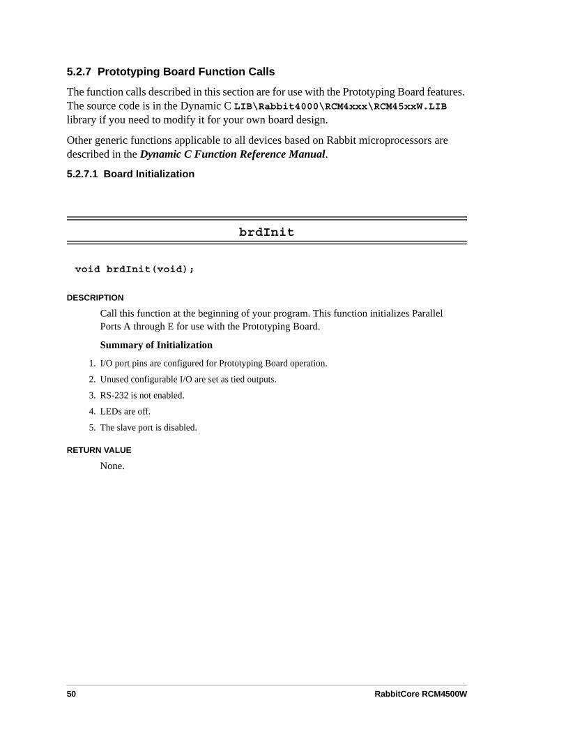
50 RabbitCore RCM4500W
5.2.7 Prototyping Board Function Calls
The function calls described in this section are for use with the Prototyping Board features. The source code is in the Dynamic C LIB\Rabbit4000\RCM4xxx\RCM45xxW.LIB library if you need to modify it for your own board design.
Other generic functions applicable to all devices based on Rabbit microprocessors are described in the Dynamic C Function Reference Manual.
5.2.7.1 Board Initialization
brdInit
void brdInit(void);
DESCRIPTION
Call this function at the beginning of your program. This function initializes Parallel Ports A through E for use with the Prototyping Board.
Summary of Initialization
1. I/O port pins are configured for Prototyping Board operation.
2. Unused configurable I/O are set as tied outputs.
3. RS-232 is not enabled.
4. LEDs are off.
5. The slave port is disabled.
RETURN VALUE
None.

User’s Manual 51
5.2.7.2 Alerts
These function calls can be found in the Dynamic C LIB\Rabbit4000\RCM4xxx\RCM4xxx.LIB library.
timedAlert
void timedAlert(unsigned long timeout);
DESCRIPTION
Polls the real-time clock until a timeout occurs. The RCM4510W will be in a low-power mode during this time. Once the timeout occurs, this function call will enable the normal power source.
PARAMETER
timeout the duration of the timeout in seconds
RETURN VALUE
None.
SEE ALSO
brdInit
digInAlert
void digInAlert(int dataport, int portbit, int value, unsigned long timeout);
DESCRIPTION
Polls a digital input for a set value or until a timeout occurs. The RCM4510W will be in a low-power mode during this time. Once a timeout occurs or the correct byte is received, this function call will enable the normal power source and exit.
PARAMETERS
dataport the input port data register to poll (e.g., PADR)
portbit the input port bit (0–7) to poll
value the value of 0 or 1 to receive
timeout the duration of the timeout in seconds (enter 0 for no timeout)
RETURN VALUE
None.

52 RabbitCore RCM4500W
5.2.8 Auxiliary I/O Pins Function Calls
The function calls described in this section are for use with the pins on the auxiliary I/O header at J4. The source code is in the Dynamic C LIB\Rabbit4000\XBee\XBEE_API.LIB library if you need to modify it for your own board design.
The sample programs in the Dynamic C SAMPLES\XBee folder illustrate the use of the function calls.
zb_io_init
int zb_io_init(void);
DESCRIPTION
Initializes the I/O on the XBee RF module. The default behavior for each pin is pre-defined, but may be overridden before the #use XBEE_API.LIB statement or by calling the appropriate macro.
J4 Pin Dynamic C Name Functionality Default
Configuration State Pull-Up Mask Bit
1 DIO_00Analog Input or
Digital I/O Analog Input Not Applicable 4
2 DIO_01Analog Input or
Digital I/O Analog Input Not Applicable 3
3 DIO_02Analog Input or
Digital I/O Analog Input Not Applicable 2
4 DIO_03Analog Input or
Digital I/O Analog Input Not Applicable 1
6 DIO_12 Digital I/O Digital Input Pulled Up 30 kΩ 10
10 DIO_05 Digital I/O Digital Output Default High 8
11 DIO_04 Digital I/O Digital Output Default High 0
13 DIO_10 Digital I/O Digital Output Default Low 11
14 DIO_11 Digital I/O Digital Input Pulled Up 30 kΩ 12

User’s Manual 53
zb_io_init (cont’d)
The pins are configured as analog inputs or as digital I/O using the following macros as examples before #use XBEE_API.LIB.
#define DIO_00 XBEE_IO_CONF_ANAIN // bit 4#define DIO_01 XBEE_IO_CONF_ANAIN // bit 3#define DIO_02 XBEE_IO_CONF_ANAIN // bit 2#define DIO_03 XBEE_IO_CONF_ANAIN // bit 1#define DIO_12 XBEE_IO_CONF_DIGIN // bit 10#define DIO_05 XBEE_IO_CONF_DIGOUT_HIGH // bit 8#define DIO_04 XBEE_IO_CONF_DIGOUT_HIGH // bit 0#define DIO_10 XBEE_IO_CONF_DIGOUT_LOW // bit 11#define DIO_11 XBEE_IO_CONF_DIGIN // bit 12
NOTE: The mask order is different than for DIO_INPUTS. While all pins can be config-ured as either inputs or outputs, only DIO_00 – DIO_03 can be configured as analog inputs.
RETURN VALUE
0 — success.
≠0 — one of the error codes returned by zb_API_ATCmdResponse()

54 RabbitCore RCM4500W
5.2.8.1 Digital I/O
zb_dio_in
int zb_dio_in(int dio);
DESCRIPTION
Reads the logic state of a pin configured as a digital input pin. This value corresponds to the dio number.
PARAMETERS
dio the Dynamic C digital input pin number (0 – ZB_MAX_PIN, valid values are 0–5, 10–12) set up in zb_io_init().
NOTE: The pin number is not the same as the DIO_xx macros described in zb_io_init(), which are used to configure the function of the pin only.
RETURN VALUE
0 or 1 — logic state.
–EINVAL — error (pin not configured as a digital input).
zb_dio_out
int zb_dio_out(int dio, int value);
DESCRIPTION
Sets the digital output value.
PARAMETERS
dio the Dynamic C digital output pin number (0 – ZB_MAX_PIN, valid values are 0–5, 10–12) set up in zb_io_init().
value the logic level (0 or 1) the pin is set to.
NOTE: The pin number is not the same as the DIO_xx macros described in zb_io_init(), which are used to configure the function of the pin only.
RETURN VALUE
0 — success.
–EINVAL — error (pin not configured as a digital output).

User’s Manual 55
5.2.8.2 Analog Inputs
zb_adc_in
int zb_adc_in(int dio);
DESCRIPTION
Reads the analog input on the designated pin and return its 10-bit value. To convert the reading to millivolts perform the following calculation.
AD (mV) = (ADIO reading / 1023) × 1200 mV
PARAMETER
dio the Dynamic C analog input pin number (0–3) set up in zb_io_init().
NOTE: The pin number is not the same as the DIO_xx macros described in zb_io_init(), which are used to configure the function of the pin only.
RETURN VALUE
0–1023 — valid data.
–EINVAL — error (pin not configured as an analog input).

56 RabbitCore RCM4500W
5.3 Upgrading Dynamic CDynamic C patches that focus on bug fixes are available from time to time. Check the Web site www.rabbit.com/support/ for the latest patches, workarounds, and bug fixes.
5.3.1 Add-On Modules
Starting with Dynamic C version 10.40, Dynamic C includes the popular µC/OS-II real-time operating system, point-to-point protocol (PPP), FAT file system, RabbitWeb, and other select libraries. Rabbit also offers for purchase the Rabbit Embedded Security Pack featuring the Secure Sockets Layer (SSL) and a specific Advanced Encryption Standard (AES) library.
In addition to the Web-based technical support included at no extra charge, a one-year telephone-based technical support subscription is also available for purchase.
Visit our Web site at www.rabbit.com for further information and complete documentation.

User’s Manual 57
6. USING THE ZIGBEE FEATURES
6.1 Introduction to the ZigBee ProtocolThe ZigBee PRO specification was ratified in April, 2007, and covers high-level communi-cation protocols for small, low-power digital modems based on the IEEE 802.15.4 stan-dard for wireless personal area networks (WPANs). The XBee RF module used by the RCM4510W operates in the 2.4 GHz industrial, scientific, and medical (ISM) radio band in most jurisdictions worldwide.
The ZigBee protocol is ideal for embedded-system applications that are characterized by low data rates and low power consumption. A network of devices using the ZigBee proto-col works via a self-organizing mesh network that can be used for industrial control, embedded sensors, data collection, smoke and intruder warning, and building automation. The power consumption of the individual device could be met for a year or longer using the originally installed battery.
A ZigBee device can be set up in one of three ways.
• As a coordinator: The coordinator serves as the root of the network tree. Each network can only have one coordinator. The coordinator stores information about the network and provides the repository for security keys.
• As a router. Routers pass data from other devices.
• As an end device. End devices contain just enough functionality to talk to their parent node (either the coordinator or a router), and cannot relay data from other devices.
An Introduction to ZigBee provides background information on the ZigBee protocol, and is available on the CD and on our Web site.
The XBee RF module used by the RCM4510W (ZB) sup-ports using the RCM4510W RabbitCore module in a mesh network. RCM4510W modules are preconfigured with ZNet 2.5 or ZB router firmware — only ZB firmware sup-ports a mesh network. Coordinator and end-device firm-ware is included in the Dynamic C installation along with a sample program to allow you to download the firmware.
The firmware used with the XBee RF modules on the RCM4510W modules is based on the API command set.
Figure 12. Mesh Network

58 RabbitCore RCM4500W
6.1.1 ZNet vs. ZB Firmware
RCM4510W modules are preconfigured with ZNet 2.5 or ZB router firmware. The firm-ware preloaded at the factory is indicated with the model number and is reflected in differ-ent part numbers (see Table 1). Older RCM4510W modules shipped with ZNet firmware and do not have a sticker on their XBee RF module.
• ZNet 2.5 firmware is supported by Dynamic C v. 10.21 and later versions. (Preview versions of the RCM4510W will work with Dynamic C v. 10.11 and later.)
• ZB firmware is supported by Dynamic C v. 10.46 and later versions.
ZigBee networks developed around the two types of firmware are essentially different net-works that are not compatible with each other. It is possible to migrate an application devel-oped with ZNet 2.5 firmware to ZB firmware by installing the ZB firmware on the XBee RF module and recompiling the application using Dynamic C v. 10.46 or later versions.
Some macros prior to Dynamic C v. 10.46 have been deprecated, but will still function with Dynamic C v. 10.46 or later versions. You can expect to see warning messages in this case. The only way to avoid this situation is to disable warning messages (not recom-mended), or to replace the macros with the new ones. The table below lists some of the commonly used macros.
See Section 6.2.2 for additional information on macros that are specific to the two types of firmware.
Original Macro New Macro
ZIGBEE_COORDINATOR XBEE_ROLE NODE_TYPE_COORD
ZIGBEE_ROUTER XBEE_ROLE NODE_TYPE_ROUTER
ZIGBEE_ENDDEV XBEE_ROLE NODE_TYPE_ENDDEV

User’s Manual 59
6.2 ZigBee Sample ProgramsIn order to run the sample programs discussed in this chapter and elsewhere in this manual,
1. Your module must be plugged into the Prototyping Board as described in Chapter 2, “Getting Started.”
2. Dynamic C must be installed and running on your PC.
3. The programming cable must connect the programming header on the RCM4510W to your PC.
4. Power must be applied to the module through the Prototyping Board.
5. The Digi® XBee USB used as the ZigBee coordinator must be connected to an avail-able USB port on your PC if you are exercising the ZigBee protocol, or you need a second RCM4510W module if so instructed.
Refer to Chapter 2, “Getting Started,” if you need further information on these steps.
To run a sample program, open it with the File menu (if it is not still open), then compile and run it by pressing F9.
Each sample program has comments that describe the purpose and function of the pro-gram. Follow the instructions at the beginning of the sample program.
The sample programs in the Dynamic C SAMPLES\RCM4500W\XBee and SAMPLES\XBee folders illustrate the use of the XBee function calls.
6.2.1 Setting Up the Digi XBee USB Coordinator
1. Connect the Digi® XBee USB acting as a ZigBee coordinator to an available USB port on your PC or workstation. Your PC should recognize the new USB hardware.
2. Compile and run the XBEE_GPIO_SERVER.C sample program in the Dynamic C SAMPLES\RCM4500W\XBee folder.
3. Open the ZigBee Utility by double-clicking XBEE_GPIO_GUI.exe in the Dynamic C Utilities\XBee GPIO GUI folder — if you have problems launching the ZigBee Utility, install a .Net Framework by double-clicking dotnetfx.exe in the Dynamic C Utilities\dotnetfx folder. You may add a shortcut to the ZigBee Utility on your desktop.
4. Confirm the following hardware setup is displayed on the “PC Settings” tab.
• 115200 baud
• Hardware flow control
• 8 data bits
• No parity
• 1 stop bit

60 RabbitCore RCM4500W
Now select the COM port the Digi® XBee USB is connected to, and click the “Open Com Port” button. The message “Radio Found” is displayed to indicate that you selected the correct COM port. The ZigBee parameters (firmware version, operating channel, PAN ID) for the Digi® XBee USB will be displayed in the “Radio Parameters” box. Go to Control Panel > System > Hardware > Device Manager > Ports on your PC if you need help in identifying the USB COM port.
5. Any ZigBee devices discovered will be displayed in the “Devices Discovered” window to the right.
If the utility times out and no ZigBee devices are displayed, you will have to reconfig-ure the Digi® XBee USB and recompile the sample program once you make sure the RCM4510W is powered up. The timeout may occur if you are doing development simultaneously with more than one ZigBee coordinator. Appendix D explains the steps to reconfigure the Digi® XBee USB.
6. Select a device with your mouse pointer and click on the selected device to select that device. This device will now be displayed in the “Selected Device” area.
7. You are now ready to interface with the RCM4510W via the ZigBee protocol. Try ping-ing the selected device by clicking the “Send Ping” button.
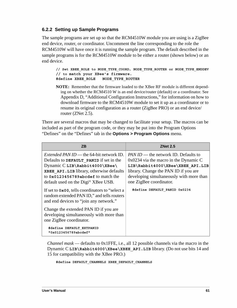
User’s Manual 61
6.2.2 Setting up Sample Programs
The sample programs are set up so that the RCM4510W module you are using is a ZigBee end device, router, or coordinator. Uncomment the line corresponding to the role the RCM4510W will have once it is running the sample program. The default described in the sample programs is for the RCM4510W module to be either a router (shown below) or an end device.
// Set XBEE_ROLE to NODE_TYPE_COORD, NODE_TYPE_ROUTER or NODE_TYPE_ENDDEV
// to match your XBee's firmware.#define XBEE_ROLE NODE_TYPE_ROUTER
NOTE: Remember that the firmware loaded to the XBee RF module is different depend-ing on whether the RCM4510 W is an end device/router (default) or a coordinator. See Appendix D, “Additional Configuration Instructions,” for information on how to download firmware to the RCM4510W module to set it up as a coordinator or to resume its original configuration as a router (ZigBee PRO) or an end device/router (ZNet 2.5).
There are several macros that may be changed to facilitate your setup. The macros can be included as part of the program code, or they may be put into the Program Options “Defines” on the “Defines” tab in the Options > Program Options menu.
Channel mask — defaults to 0x1FFE, i.e., all 12 possible channels via the macro in the Dynamic C LIB\Rabbit4000\XBee\XBEE_API.LIB library. (Do not use bits 14 and 15 for campatibility with the XBee PRO.)
#define DEFAULT_CHANNELS XBEE_DEFAULT_CHANNELS
ZB ZNet 2.5
Extended PAN ID — the 64-bit network ID. Defaults to DEFAULT_PANID if set in the Dynamic C LIB\Rabbit4000\XBee\XBEE_API.LIB library, otherwise defaults to 0x0123456789abcdef to match the default used on the Digi® XBee USB.
If set to 0x00, tells coordinators to “select a random extended PAN ID,” and tells routers and end devices to “join any network.”
Change the extended PAN ID if you are developing simultaneously with more than one ZigBee coordinator.
#define DEFAULT_EXTPANID "0x0123456789abcdef"
PAN ID — the network ID. Defaults to 0x0234 via the macro in the Dynamic C LIB\Rabbit4000\XBee\XBEE_API.LIB library. Change the PAN ID if you are developing simultaneously with more than one ZigBee coordinator.#define DEFAULT_PANID 0x0234

62 RabbitCore RCM4500W
Node ID — the ID of your particular node via the macro in the Dynamic C LIB\Rabbit4000\XBee\XBEE_API.LIB library. Each node should have a unique identifier of up to 20 printable characters.
• Defaults to RabbitXBee.
• Can be set to a global variable, or to a function that returns a pointer to a static buffer.
#define NODEID_STR "RabbitXBee"
The XBee sample programs in the Dynamic C SAMPLES\XBee folder illustrate the use of AT commands with the XBee RF module.
• AT_INTERACTIVE.C—This sample program shows how to set up and use AT commands with the XBee RF module.
The program will print out a list of AT commands in the Dynamic C STDIO window. You may type in either “ATxx” or just the “xx” part of the command.
• Use just the AT command to read any of the values.
• Use [AT]xx yyyy (where the y is an integer up to 32 bits) to set any of the “set or read” values. (Note that this works for NI, the node identifier, where the data will be a Node ID.string in quotes — [AT]NI "Node ID string” where the quotes contain the string data).
Note that you can also use hex notation by prefixing the parameter with 0x and using an even number of hex characters.
• Type “menu” to redisplay the menu of commands.
• Press F4 to exit and close the STDIO window.
• AT_RUNONCE.C—This sample program uses many of the most important and useful AT commands. Several commands can either set a parameter or read it. This sample program simply reads the parameters and displays the results.
Compile and run this sample program. The program will display the results in the Dynamic C STDIO window.

User’s Manual 63
The XBee sample programs in the Dynamic C SAMPLES\RCM4500W\XBee folder exercise the XBee function calls on the XBee RF module on the RCM4510W.
• SLEEPMODE.C—This sample program shows how to place the RCM4510W module in the “sleep” mode where most power is removed from the RCM4510W module. Power is restored once a message is received or after a specified time interval. This sample program demonstrates waking after a specified time interval.
Sleeping only works on end devices, so the XBEE_ROLE macro is set to NODE_TYPE_ENDDEV in this sample program. Because the XBee RF module turns the Rabbit proces-sor off and on, a serial terminal emulator is required once the program has been compiled.
1. Compile and run the sample program on the RCM4510W module.
2. Once the sample program is running, choose “Close Connection” from the in Dynamic C Run menu, and unplug the AC adapter supply power to the Prototyping Board.
3. Connect the DIAG connector instead of the PROG connector on the programming cable to the RCM4510 programming header.
4. Open the serial port in your serial terminal emulator such as TeraTerm or Hyperterminal to connect to the serial port at 57600 baud.
5. Plug the AC adapter back in to apply power to the Prototyping Board once again.
Once the XBee RF module on the RCM4510W completes its initialization (it joins the network), you will be prompted to enter a “sleep” time in milliseconds — enter the number followed by the Enter key. There will be a delay of a few seconds before the RCM4510W module powers off. When the RCM4510W module powers back up, it will begin running this program again from the beginning.
NOTE: This sample program does not demonstrate the saving state. State information may be saved in battery-backed RAM before the RCM4510W module is placed in the sleep mode.
64 RabbitCore RCM4500W
• SLEEPMODE2.C—This sample program shows how to place the RCM4510W module in the “sleep” mode where most power is removed from the RCM4510W module. Power is restored once a message is received or after a specified time interval. This sample program demonstrates waking after a specified time interval.
Sleeping only works on end devices, so the XBEE_ROLE macro is set to NODE_TYPE_ENDDEV in this sample program. Because the XBee RF module turns the Rabbit proces-sor off and on, a serial terminal emulator is required once the program has been compiled.
1. Compile and run the sample program on the RCM4510W module.
2. Once the sample program is running, choose “Close Connection” from the in Dynamic C Run menu, and unplug the AC adapter supply power to the Prototyping Board.
3. Connect the DIAG connector instead of the PROG connector on the programming cable to the RCM4510 programming header.
4. Open the serial port in your serial terminal emulator such as TeraTerm or Hyperterminal to connect to the serial port at 57600 baud.
5. Plug the AC adapter back in to apply power to the Prototyping Board once again.
Once the XBee RF module on the RCM4510W completes its initialization (it joins the network), you will be prompted to enter three values that control the XBee RF module's sleep mode — enter the values followed by the Enter key each time. Once you have entered these values via the serial terminal emulator, press any key to initiate the sleep mode. There will be a delay of a few seconds before the RCM4510W module powers off. When the RCM4510W module powers back up, it will begin running this program again from the beginning.
NOTE: This sample program does not demonstrate the saving state. State information may be saved in battery-backed RAM before the RCM4510W module is placed in the sleep mode.
• XBEE_GPIO_SERVER.C—This sample program shows how to set up and use endpoints and clusters. It is meant to be run with the Windows GUI client (installed in Dynamic C’s Utilities directory) and a Digi USB XBee coordinator or with the GPIO client sample program (SAMPLES/XBEE/XBEE_GPIO_CLIENT.C) running on an RCM4510W RabbitCore module or on a single-board computer with a separate XBee RF module.
Compile and run this sample program with the RCM4510W RabbitCore module installed on the Prototyping Board. Run the Windows GUI client (XBEE_GPIO_GUI.exe in the Dynamic C Utilities\XBee GPIO GUI folder) on your PC. Configure the GUI cli-ent to connect to the Digi USB XBee coordinator and scan for devices. Make sure the RCM4510W and the Digi USB XBee coordinator are configured with the same PAN ID or extended PAN ID.
If you run the XBEE_GPIO_CLIENT.C sample program on another board with an XBee RF module, set the PAN IDs to match between the client and the server sample programs.
Now select the GPIO server and use the GUI interface on the PC, or the command-line client on another XBee-equipped board to view the server's inputs and change its outputs. For example, you can toggle the LEDs on the Prototyping Board on/off.

User’s Manual 65
6.3 Using the Sleep ModeThe RCM4510W RabbitCore module has two components that are involved when the sleep mode is invoked — the XBee RF module and the Rabbit 4000 microprocessor.
End devices, unlike coordinators and routers, can enter a low-power sleep mode. This sleep mode is controlled by the XBee RF module, and fully powers down the Rabbit 4000 microprocessor for significant savings in power use.
The sleep mode can only be initiated while the RCM4510W is in the Run Mode (see Section 4.3.1 for more information on the Program Mode and the Run Mode).
Once the XBee RF module on the RCM4510W is operating in the sleep mode, it will peri-odically wake up and poll its parent router or coordinator to determine whether there is an incoming message. If one is found, the message will be received and the Rabbit 4000 microprocessor will be restarted. Otherwise the XBee RF module will return to sleep. Depending on how the sleep mode is configured, the XBee RF module may also restart the Rabbit 4000 microprocessor after a timeout has passed even if no message is received.
The sleep mode is controlled by the XBee RF module with a set of user-configurable parameters. Although a parameter can be set with an AT command, the recommended pro-cedure is to only initiate the sleep mode using either the zb_Rabbit_poweroff() or the xb_sleep() function call.
The most important parameters are ST, SP, and SN. Together they control the duration of sleep and wake times.
• ST is measured in milliseconds, and controls the amount of time the XBee RF module, and consequently the Rabbit microprocessor, will stay awake waiting for RF or serial data before going to sleep. If any data are received, the ST counter will be reset. The Rabbit 4000 microprocessor needs approximately two seconds to boot and reinitialize the XBee RF module, so the value of ST must be at least 2000.
• SP is measured in 0.01 second intervals and controls the length of sleep for the XBee RF module. The XBee RF module will operate in a low-power mode for the time spec-ified in SP, and then wake up briefly to poll its parent for a message. Depending on the value of SN, the XBee RF module may then either return to sleep or wake up the Rabbit 4000 microprocessor. There are several important considerations for SP.
- The ZigBee parent (coordinator or router) can buffer a message for only 30 seconds,so SP must be set to no more than 28 seconds.
- While SP is measured in 0.01 second intervals, it only has a 0.25 second resolution, and any value sent to the XBee RF module is rounded automatically.
- The overhead of polling for a message was tested internally and was found to be approximately 20 ms. Thus a hypothetical sleep with SN = 100 and SP = 100 will not wake the Rabbit microproces-sor until 102 seconds have elapsed (rather than the expected 100 seconds). The polling time may be sensitive to network conditions and firmware version, so you should perform your own testing if timing is critical.
• SN determines how many multiples of SP the radio will sleep before waking up if no message was otherwise received.

66 RabbitCore RCM4500W
Two additional parameters are described below for completeness.
• WH determines how long the XBee RF module will hold a message for the RCM4510W to receive. Like ST, this parameter must be set carefully to ensure no mes-sages are lost at startup. It is currently set to 3 seconds.
• SO is a conditional flag and determines whether the XBee RF module will wake the Rabbit 4000 microprocessor if SN and SP expire, or whether both parameters are reset to resume the sleep mode immediately.
There are several important ramifications and interactions with the operation of other function calls to consider when using the sleep mode.
• When the Rabbit 4000 microprocessor wakes up from sleep, both the RCM4510W and user application will fully restart. The user program will not resume from the point at which it went to sleep.
• User data should be initialized prior to calling xbee_init() to ensure that cluster functions or the default message handler process an incoming wake message correctly.
• When sleep is initiated, both the XBee RF module and the Rabbit 4000 microprocessor will remain awake for the time in ST before actually powering down the Rabbit 4000 microprocessor and entering a low-power mode. Any messages received during this time period will cause the counter to reset, and must be processed immediately or be lost.
• An end device is always preparing to sleep. Use xb_stayawake() to set ST to its maximum value and periodically send data to the XBee RF module to keep it awake. Blocking for long periods of time and failing to call xb_tick() for more than 30 seo-conds could result in the RCM4510W going to sleep unexpectedly.
The SLEEPMODE.C and SLEEPMODE2.C sample programs in the Dynamic C SAMPLES\RCM4500W\XBEE folder and the function documentation for zb_Rabbit_poweroff() and xb_sleep() provide more specific information regarding the implementation and use of the sleep mode.

User’s Manual 67
6.4 Dynamic C Function CallsFunction calls for use with the XBee RF modules are in the Dynamic C LIB\Rabbit4000\XBee\XBEE_API.LIB library. These ZigBee specific function calls are described in An Introduction to ZigBee, which is included in the online documentation set.
6.5 Where Do I Go From Here?NOTE: If you purchased your RCM4510W through a distributor or through a Rabbit
partner, contact the distributor or partner first for technical support.
If there are any problems at this point:
• Use the Dynamic C Help menu to get further assistance with Dynamic C.
• Check the Rabbit Technical Bulletin Board and forums at www.rabbit.com/support/bb/ and at www.rabbitcom/forums/.
• Use the Technical Support e-mail form at www.rabbit.com/support/.
If the sample programs ran fine, you are now ready to go on.
An Introduction to ZigBee provides background information on the ZigBee protocol, and is available on the CD and on our Web site.
Digi’s XBee® OEM RF Modules provides complete information for the XBee RF module used on the RCM4510W RabbitCore modules, provides background information on the ZigBee PRO protocol, and is available at ftp1.digi.com/support/documentation/90000976_a.pdf..

68 RabbitCore RCM4500W

User’s Manual 69
APPENDIX A. RCM4510WSPECIFICATIONS
Appendix A provides the specifications for the RCM4510W,and describes the conformal coating.
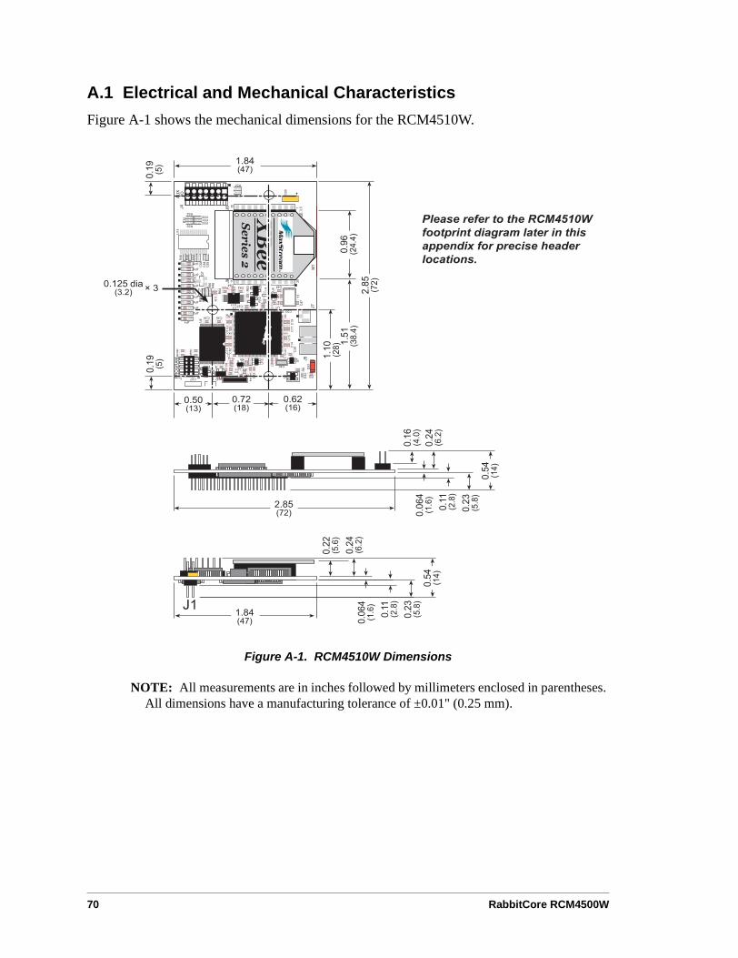
70 RabbitCore RCM4500W
A.1 Electrical and Mechanical CharacteristicsFigure A-1 shows the mechanical dimensions for the RCM4510W.
Figure A-1. RCM4510W Dimensions
NOTE: All measurements are in inches followed by millimeters enclosed in parentheses. All dimensions have a manufacturing tolerance of ±0.01" (0.25 mm).
&%!-%!!#*&-##7%!# -&! !8
>?
>?
>?
>?
>
?
>
?
>
?
>
?
>
?
>
?
>
?
>
?
>?
>?
>?
>?
@ 813>?
>?
>
?
>?
>?
>
?
>?
>
?
>
?

User’s Manual 71
It is recommended that you allow for an “exclusion zone” of 0.04" (1 mm) around the RCM4510W in all directions when the RCM4510W is incorporated into an assembly that includes other printed circuit boards. An “exclusion zone” of 0.08" (2 mm) is recom-mended below the RCM4510W when the RCM4510W is plugged into another assembly. Figure A-2 shows this “exclusion zone.”
Figure A-2. RCM4510W “Exclusion Zone”
NOTE: There is an antenna associated with the RCM4510W RabbitCore modules. The antenna is on the XBee RF modules for the standard versions of the RCM4510W, and is on the printed circuit board near the shielded modem below header J4. Do not use any RF-absorbing materials in these vicinities in order to realize the maximum range.
7 &!5!
>?
>
?
>?
>?
>?
>?
>
?
>?
%&
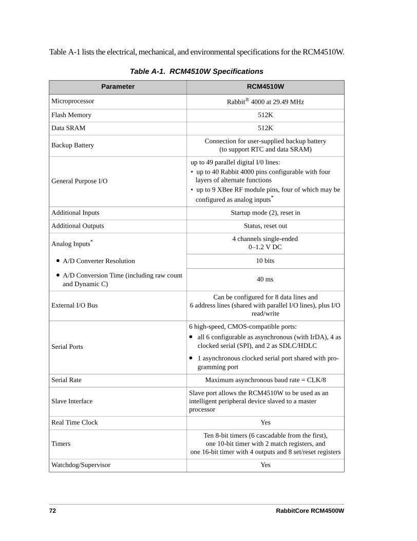
72 RabbitCore RCM4500W
Table A-1 lists the electrical, mechanical, and environmental specifications for the RCM4510W.
Table A-1. RCM4510W Specifications
Parameter RCM4510W
Microprocessor Rabbit® 4000 at 29.49 MHz
Flash Memory 512K
Data SRAM 512K
Backup Battery Connection for user-supplied backup battery(to support RTC and data SRAM)
General Purpose I/O
up to 49 parallel digital I/0 lines:• up to 40 Rabbit 4000 pins configurable with four
layers of alternate functions• up to 9 XBee RF module pins, four of which may be
configured as analog inputs*
Additional Inputs Startup mode (2), reset in
Additional Outputs Status, reset out
Analog Inputs* 4 channels single-ended0–1.2 V DC
• A/D Converter Resolution 10 bits
• A/D Conversion Time (including raw count and Dynamic C)
40 ms
External I/O BusCan be configured for 8 data lines and
6 address lines (shared with parallel I/O lines), plus I/O read/write
Serial Ports
6 high-speed, CMOS-compatible ports:• all 6 configurable as asynchronous (with IrDA), 4 as
clocked serial (SPI), and 2 as SDLC/HDLC
• 1 asynchronous clocked serial port shared with pro-gramming port
Serial Rate Maximum asynchronous baud rate = CLK/8
Slave InterfaceSlave port allows the RCM4510W to be used as an intelligent peripheral device slaved to a master processor
Real Time Clock Yes
TimersTen 8-bit timers (6 cascadable from the first),one 10-bit timer with 2 match registers, and
one 16-bit timer with 4 outputs and 8 set/reset registers
Watchdog/Supervisor Yes

User’s Manual 73
Pulse-Width Modulators4 channels synchronized PWM with 10-bit counter4 channels variable-phase or synchronized PWM with 16-bit counter
Input Capture 2-channel input capture can be used to time input signals from various port pins
Quadrature Decoder 2-channel quadrature decoder accepts inputsfrom external incremental encoder modules
Power with ZigBee® Modem(pins unloaded)
3.3 V.DC ±5%
150 mA @ 3.3 V while transmitting/receiving80 mA @ 3.3 V while not transmitting/receiving
<20 µA @ 3.3 V while asleep
Operating Temperature -40°C to +85°C
Humidity 5% to 95%, noncondensing
ConnectorsOne 2 × 7, 2 mm pitch IDC signal header
One 2 × 25, 1.27 mm pitch IDC signal headerOne 2 × 5, 1.27 mm pitch IDC programming header
Board Size with XBee RF module Installed 1.84" × 2.85" × 0.54"(47 mm × 72 mm × 14 mm)
XBee RF Module
RF Module Digi International XBee®
Compliance 802.15.4 standard (ZigBee compliant)
* These I/O pins from the XBee RF module are available on auxiliary I/O header J4.
Table A-1. RCM4510W Specifications (continued)
Parameter RCM4510W

74 RabbitCore RCM4500W
A.1.1 XBee RF Module
Table A-2 shows the XBee RF module specifications.
The XBee RF module that consists of discrete components on the preview versions of the RCM4510W module has the same specifications.
Table A-2. XBee RF Module Specifications
Parameter Specification
RF Module Digi International XBee®
Compliance 802.15.4 standard (ZigBee compliant)
Frequency ISM 2.4 GHz
Performance
Indoor Range 100 ft (30 m)
Outdoor Line-of-Sight Range 300 ft (90 m)
Transmit Power Output 1 mW (0 dBm)
RF Data Rate 250,000 bps
Receiver Sensitivity -92 dBm (1% PER)
Antenna Chip antenna
Supported Network Topologies
• Point-to-point
• Point-to-multipoint
• Peer-to-peer
• Mesh
Number of RF Channels 16 direct-sequence channels
Filtration Options
• PAN ID
• Channel
• Source/destination addresses
Power (typical)Transmit 40 mA @ 3.3 V DC ±5%
Idle/Receive 40 mA @ 3.3 V DC ±5%

User’s Manual 75
A.1.2 Headers
The RCM4510W uses a header at J1 for physical connection to other boards. J1 is a 2 × 25 SMT header with a 1.27 mm pin spacing. J2, the programming port, is a 2 × 5 header with a 1.27 mm pin spacing. Header J4 supplies auxiliary I/O supported by the XBee RF mod-ule, and is a 2 × 7 SMT header with a 2 mm pin spacing
Figure A-3 shows the layout of another board for the RCM4510W to be plugged into. These reference design values are relative to one of the mounting holes.
Figure A-3. User Board Footprint for RCM4510W
%&))-5/12-
>?
>?
>? +A
>?
>?
>?
>?
+A>?
>?
>?
>?
>?
>?
>?
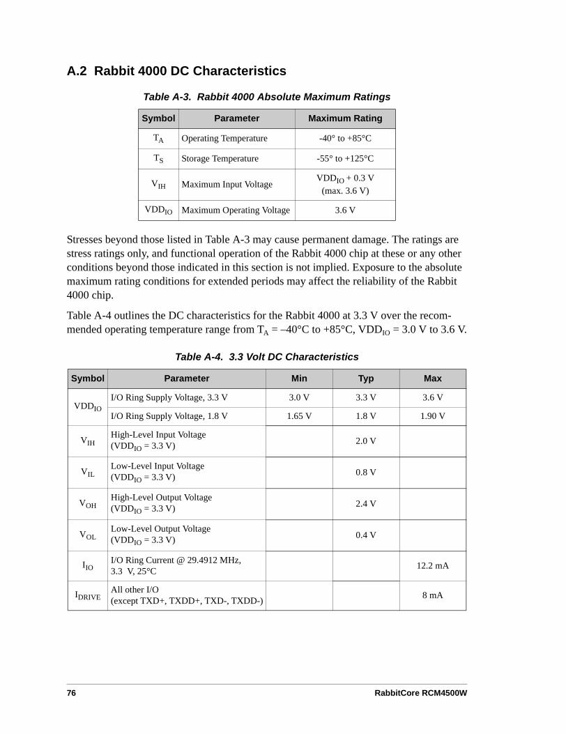
76 RabbitCore RCM4500W
A.2 Rabbit 4000 DC Characteristics
Stresses beyond those listed in Table A-3 may cause permanent damage. The ratings are stress ratings only, and functional operation of the Rabbit 4000 chip at these or any other conditions beyond those indicated in this section is not implied. Exposure to the absolute maximum rating conditions for extended periods may affect the reliability of the Rabbit 4000 chip.
Table A-4 outlines the DC characteristics for the Rabbit 4000 at 3.3 V over the recom-mended operating temperature range from TA = –40°C to +85°C, VDDIO = 3.0 V to 3.6 V.
Table A-3. Rabbit 4000 Absolute Maximum Ratings
Symbol Parameter Maximum Rating
TA Operating Temperature -40° to +85°C
TS Storage Temperature -55° to +125°C
VIH Maximum Input VoltageVDDIO + 0.3 V
(max. 3.6 V)
VDDIO Maximum Operating Voltage 3.6 V
Table A-4. 3.3 Volt DC Characteristics
Symbol Parameter Min Typ Max
VDDIOI/O Ring Supply Voltage, 3.3 V 3.0 V 3.3 V 3.6 V
I/O Ring Supply Voltage, 1.8 V 1.65 V 1.8 V 1.90 V
VIHHigh-Level Input Voltage(VDDIO = 3.3 V) 2.0 V
VILLow-Level Input Voltage(VDDIO = 3.3 V) 0.8 V
VOHHigh-Level Output Voltage(VDDIO = 3.3 V) 2.4 V
VOLLow-Level Output Voltage(VDDIO = 3.3 V) 0.4 V
IIOI/O Ring Current @ 29.4912 MHz, 3.3 V, 25°C 12.2 mA
IDRIVEAll other I/O(except TXD+, TXDD+, TXD-, TXDD-) 8 mA
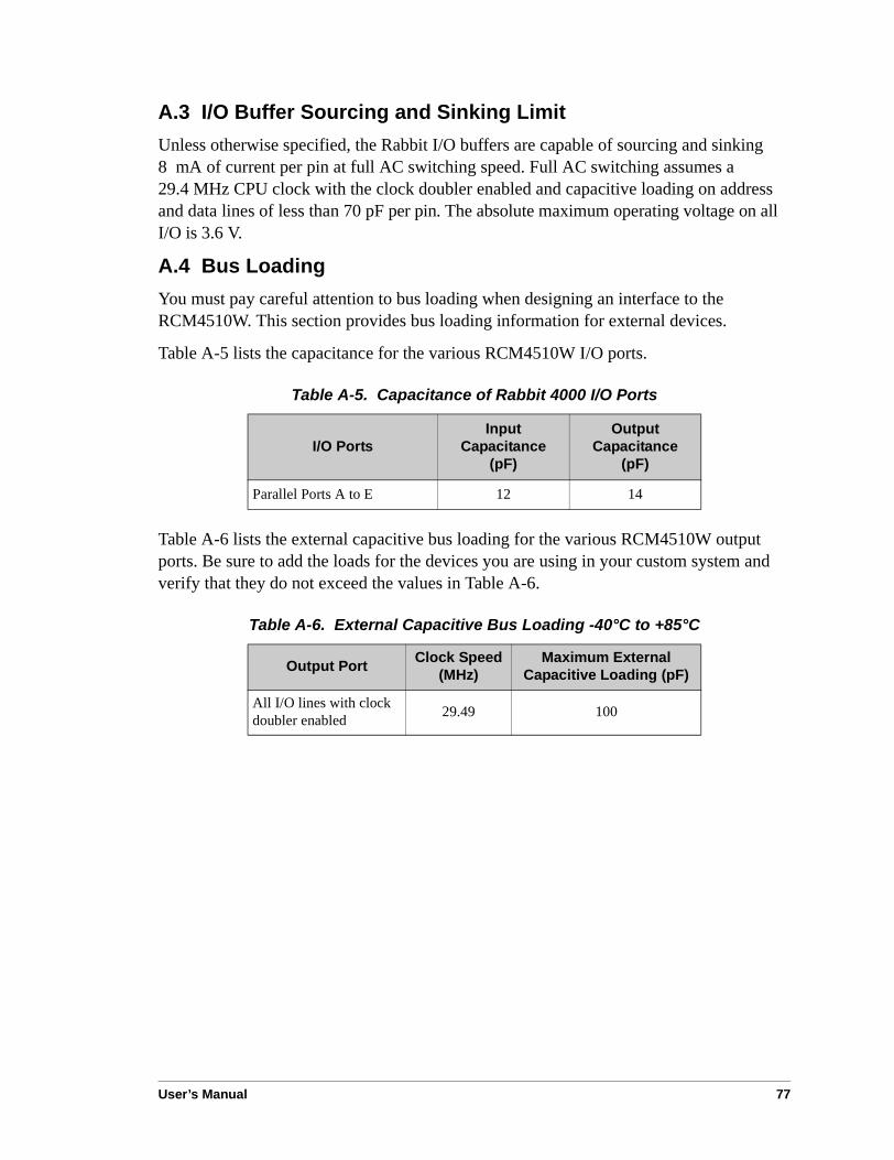
User’s Manual 77
A.3 I/O Buffer Sourcing and Sinking LimitUnless otherwise specified, the Rabbit I/O buffers are capable of sourcing and sinking 8 mA of current per pin at full AC switching speed. Full AC switching assumes a 29.4 MHz CPU clock with the clock doubler enabled and capacitive loading on address and data lines of less than 70 pF per pin. The absolute maximum operating voltage on all I/O is 3.6 V.
A.4 Bus LoadingYou must pay careful attention to bus loading when designing an interface to the RCM4510W. This section provides bus loading information for external devices.
Table A-5 lists the capacitance for the various RCM4510W I/O ports.
Table A-6 lists the external capacitive bus loading for the various RCM4510W output ports. Be sure to add the loads for the devices you are using in your custom system and verify that they do not exceed the values in Table A-6.
Table A-5. Capacitance of Rabbit 4000 I/O Ports
I/O PortsInput
Capacitance(pF)
Output Capacitance
(pF)
Parallel Ports A to E 12 14
Table A-6. External Capacitive Bus Loading -40°C to +85°C
Output Port Clock Speed (MHz)
Maximum External Capacitive Loading (pF)
All I/O lines with clock doubler enabled 29.49 100

78 RabbitCore RCM4500W
Figure A-4 shows a typical timing diagram for the Rabbit 4000 microprocessor external I/O read and write cycles.
Figure A-4. External I/O Read and Write Cycles—No Extra Wait States
NOTE: /IOCSx can be programmed to be active low (default) or active high.
38/
38/
7&94!7,6
:
BCD
7&94!7,6
:
BCD
E
E
"&#
9
%
"&#
BCD
+'-65
F),8
9
9
9
9
"&#
9
9
"&#
BCD
9 9
9
%
9
9
%
"&# "&#
GH! !GH
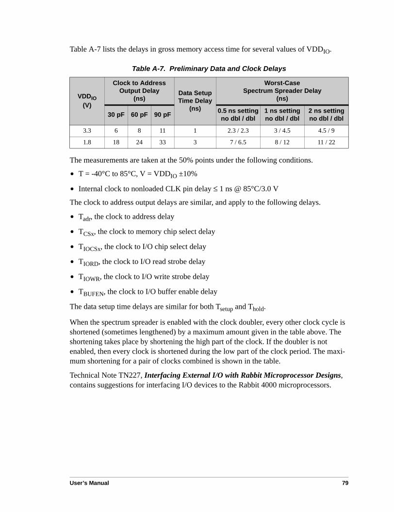
User’s Manual 79
Table A-7 lists the delays in gross memory access time for several values of VDDIO.
The measurements are taken at the 50% points under the following conditions.
• T = -40°C to 85°C, V = VDDIO ±10%
• Internal clock to nonloaded CLK pin delay ≤ 1 ns @ 85°C/3.0 V
The clock to address output delays are similar, and apply to the following delays.
• Tadr, the clock to address delay
• TCSx, the clock to memory chip select delay
• TIOCSx, the clock to I/O chip select delay
• TIORD, the clock to I/O read strobe delay
• TIOWR, the clock to I/O write strobe delay
• TBUFEN, the clock to I/O buffer enable delay
The data setup time delays are similar for both Tsetup and Thold.
When the spectrum spreader is enabled with the clock doubler, every other clock cycle is shortened (sometimes lengthened) by a maximum amount given in the table above. The shortening takes place by shortening the high part of the clock. If the doubler is not enabled, then every clock is shortened during the low part of the clock period. The maxi-mum shortening for a pair of clocks combined is shown in the table.
Technical Note TN227, Interfacing External I/O with Rabbit Microprocessor Designs, contains suggestions for interfacing I/O devices to the Rabbit 4000 microprocessors.
Table A-7. Preliminary Data and Clock Delays
VDDIO(V)
Clock to Address Output Delay
(ns)Data Setup Time Delay
(ns)
Worst-Case Spectrum Spreader Delay
(ns)
30 pF 60 pF 90 pF 0.5 ns settingno dbl / dbl
1 ns settingno dbl / dbl
2 ns settingno dbl / dbl
3.3 6 8 11 1 2.3 / 2.3 3 / 4.5 4.5 / 9
1.8 18 24 33 3 7 / 6.5 8 / 12 11 / 22

80 RabbitCore RCM4500W
A.5 Conformal CoatingThe areas around the 32 kHz real-time clock crystal oscillator have had the Dow Corning silicone-based 1-2620 conformal coating applied. The conformally coated area is shown in Figure A-5. The conformal coating protects these high-impedance circuits from the effects of moisture and contaminants over time.
Figure A-5. RCM4510W Areas Receiving Conformal Coating
Any components in the conformally coated area may be replaced using standard soldering procedures for surface-mounted components. A new conformal coating should then be applied to offer continuing protection against the effects of moisture and contaminants.
NOTE: For more information on conformal coatings, refer to Rabbit’s Technical Note TN303, Conformal Coatings, which is included with the online documentation.
)2I)/(3,,J .)3-'83/'3
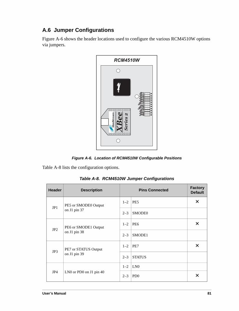
User’s Manual 81
A.6 Jumper ConfigurationsFigure A-6 shows the header locations used to configure the various RCM4510W options via jumpers.
Figure A-6. Location of RCM4510W Configurable Positions
Table A-8 lists the configuration options.
Table A-8. RCM4510W Jumper Configurations
Header Description Pins Connected Factory Default
JP1 PE5 or SMODE0 Outputon J1 pin 37
1–2 PE5 ×2–3 SMODE0
JP2 PE6 or SMODE1 Outputon J1 pin 38
1–2 PE6 ×2–3 SMODE1
JP3 PE7 or STATUS Outputon J1 pin 39
1–2 PE7 ×2–3 STATUS
JP4 LN0 or PD0 on J1 pin 401–2 LN0
2–3 PD0 ×

82 RabbitCore RCM4500W
NOTE: The jumper connections are made using 0 Ω surface-mounted resistors.
JP5 LN2 or PD2 on J1 pin 421–2 LN2
2–3 PD2 ×
JP6 LN4 or PD4 on J1 pin 441–2 LN4
2–3 PD4 ×
JP7 LN6 or PD6 on J1 pin 461–2 LN6
2–3 PD6 ×
JP8 LN7 or PD7 on J1 pin 471–2 LN7
2–3 PD7 ×
JP9 LN5 or PD5 on J1 pin 451–2 LN5
2–3 PD5 ×
JP10 LN3 or PD3 on J1 pin 431–2 LN3
2–3 PD3 ×
JP11 LN1 or PD1 on J2 pin 411–2 LN1
2–3 PD1 ×
Table A-8. RCM4510W Jumper Configurations (continued)
Header Description Pins Connected Factory Default

User’s Manual 83
APPENDIX B. PROTOTYPING BOARD
Appendix B describes the features and accessories of the Proto-typing Board, and explains the use of the Prototyping Board todemonstrate the RCM4510W and to build prototypes of yourown circuits. The Prototyping Board has power-supply connec-tions and also provides some basic I/O peripherals (RS-232,LEDs, and switches), as well as a prototyping area for moreadvanced hardware development.

84 RabbitCore RCM4500W
B.1 IntroductionThe Prototyping Board included in the Development Kit makes it easy to connect an RCM4510W module to a power supply and a PC workstation for development. It also pro-vides some basic I/O peripherals (RS-232, LEDs, and switches), as well as a prototyping area for more advanced hardware development.
For the most basic level of evaluation and development, the Prototyping Board can be used without modification.
As you progress to more sophisticated experimentation and hardware development, modifications and additions can be made to the board without modifying the RCM4510W module.
The Prototyping Board is shown below in Figure B-1, with its main features identified.
Figure B-1. Prototyping Board
!
"
##
!
!
$
%
!"#
"
"
"
"
#
#
#
#
!#&
"
"
"
"
#
#
#
#
!
!
!
#&
)E'/#
'+'-E1-.F
+'/#+
!0 !0 328 "6+'+
%)86,'
#9-'2+1)2 G'38'/+'/
E1-.F'+
/)-)-J5127/'3
6//'2-='3+6/'('2-
G'38'/+
F/)67F=G),'/)-)-J5127 /'3
23,)7
)E'/256-
"3.K65"3--'/J
=G'38'/
%)86,'
)22'.-)/
%-328)II)62-127
/)-)-J5127/'3

User’s Manual 85
B.1.1 Prototyping Board Features
• Power Connection—A a 3-pin header is provided for connection to the power supply. Note that the 3-pin header is symmetrical, with both outer pins connected to ground and the center pin connected to the raw V+ input. The cable of the AC adapter provided with the North American version of the Development Kit is terminated with a header plug that connects to the 3-pin header in either orientation. The header plug leading to bare leads provided for overseas customers can be connected to the 3-pin header in either orientation.
Users providing their own power supply should ensure that it delivers 8–24 V DC at 8 W. The voltage regulators will get warm while in use.
• Regulated Power Supply—The raw DC voltage provided at the 3-pin header is routed to a 5 V switching voltage regulator, then to a separate 3.3 V linear regulator. The regulators provide stable power to the RCM4510W module and the Prototyping Board.
• Power LED—The power LED lights whenever power is connected to the Prototyping Board.
• Reset Switch—A momentary-contact, normally open switch is connected directly to the RCM4510W’s /RESET_IN pin. Pressing the switch forces a hardware reset of the system.
• I/O Switches and LEDs—Two momentary-contact, normally open switches are con-nected to the PB4 and PB5 pins of the RCM4510W module and may be read as inputs by sample applications.
Two LEDs are connected to the PB2 and PB3 pins of the RCM4510W module, and may be driven as output indicators by sample applications.
• Prototyping Area—A generous prototyping area has been provided for the installation of through-hole components. +3.3 V, +5 V, and Ground buses run around the edge of this area. Several areas for surface-mount devices are also available. (Note that there are SMT device pads on both top and bottom of the Prototyping Board.) Each SMT pad is connected to a hole designed to accept a 30 AWG solid wire.
• Module Extension Header—The complete pin set of the RCM4510W module is duplicated at header J2. Developers can solder wires directly into the appropriate holes, or, for more flexible development, a 2 × 25 header strip with a 0.1" pitch can be sol-dered into place. See Figure B-4 for the header pinouts.
NOTE: The same Prototyping Board can be used for several series of RabbitCore mod-ules, and so the signals at J2 depend on the signals available on the specific RabbitCore module.

86 RabbitCore RCM4500W
• Analog Inputs Header—The analog signals from the RabbitCore module are pre-sented at header J3 on the Prototyping Board. These analog signals are connected via attenuator/filter circuits on the Prototyping Board to the corresponding analog inputs on the RCM4510W module.
NOTE: No analog signals are available on the Prototyping Board with the RCM4510W RabbitCore module installed since no analog signals are present on the RCM4510W’s header J1. The auxiliary I/O on the RCM4510W’s header J4 cannot be used with the Prototyping Board without modifying the Prototyping Board.
• RS-232—Two 3-wire or one 5-wire RS-232 serial ports are available on the Prototyp-ing Board at header J4. A 10-pin 0.1" pitch header strip installed at J4 allows you to connect a ribbon cable that leads to a standard DE-9 serial connector.
• Current Measurement Option—You may cut the trace below header JP1 on the bottom side of the Prototyping Board and install a 1 × 2 header strip from the Develop-ment Kit to allow you to use an ammeter across the pins to measure the current drawn from the +5 V supply. Similarly, you may cut the trace below header JP2 on the bottom side of the Prototyping Board and install a 1 × 2 header strip from the Development Kit to allow you to use an ammeter across the pins to measure the current drawn from the +3.3 V supply.
• Backup Battery—A 2032 lithium-ion battery rated at 3.0 V, 220 mA·h, provides battery backup for the RCM4510W SRAM and real-time clock.
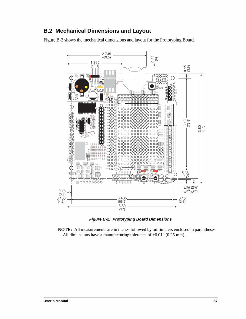
User’s Manual 87
B.2 Mechanical Dimensions and LayoutFigure B-2 shows the mechanical dimensions and layout for the Prototyping Board.
Figure B-2. Prototyping Board Dimensions
NOTE: All measurements are in inches followed by millimeters enclosed in parentheses. All dimensions have a manufacturing tolerance of ±0.01" (0.25 mm).
!
"
##
!
!
$
%
!"#
"
"
"
"
#
#
#
#
!#&
"
"
"
"
#
#
#
#
!
!
!
#&
>?
>?
>?
>?
>?
>?
>
?
>
?
>?
>
?
>?
>
?
>?
>?

88 RabbitCore RCM4500W
Table B-1 lists the electrical, mechanical, and environmental specifications for the Proto-typing Board.
B.3 Power SupplyThe RCM4510W requires a regulated 3.0 V – 3.6 V DC power source to operate. Depend-ing on the amount of current required by the application, different regulators can be used to supply this voltage.
The Prototyping Board has an onboard +5 V switching power regulator from which a +3.3 V linear regulator draws its supply. Thus both +5 V and +3.3 V are available on the Prototyping Board.
The Prototyping Board itself is protected against reverse polarity by a Shottky diode at D2 as shown in Figure B-3.
Figure B-3. Prototyping Board Power Supply
Table B-1. Prototyping Board Specifications
Parameter Specification
Board Size 3.80" × 3.80" × 0.48" (97 mm × 97 mm × 12 mm)
Operating Temperature 0°C to +70°C
Humidity 5% to 95%, noncondensing
Input Voltage 8 V to 24 V DC
Maximum Current Draw(including user-added circuits)
800 mA max. for +3.3 V supply,1 A total +3.3 V and +5 V combined
Prototyping Area 1.3" × 2.0" (33 mm × 50 mm) throughhole, 0.1" spacing, additional space for SMT components
Connectors
One 2 × 25 header socket, 1.27 mm pitch, to accept RCM4510WOne 1 × 3 IDC header for power-supply connectionOne 2 × 5 IDC RS-232 header, 0.1" pitchTwo unstuffed header locations for analog and RCM4510W signals25 unstuffed 2-pin header locations for optional configurations
# %##
%#
L&
!
L& L&
!
LG
"
% G %# #
L&

User’s Manual 89
B.4 Using the Prototyping BoardThe Prototyping Board is actually both a demonstration board and a prototyping board. As a demonstration board, it can be used to demonstrate the functionality of the RCM4510W right out of the box without any modifications to either board.
The Prototyping Board comes with the basic components necessary to demonstrate the operation of the RCM4510W. Two LEDs (DS2 and DS3) are connected to PB2 and PB3, and two switches (S2 and S3) are connected to PB4 and PB5 to demonstrate the interface to the Rabbit 4000 microprocessor. Reset switch S1 is the hardware reset for the RCM4510W.
The Prototyping Board provides the user with RCM4510W connection points brought out conveniently to labeled points at header J2 on the Prototyping Board. Although header J2 is unstuffed, a 2 × 25 header is included in the bag of parts. RS-232 signals (Serial Ports C and D) are available on header J4. A header strip at J4 allows you to connect a ribbon cable, and a ribbon cable to DB9 connector is included with the Development Kit. The pinouts for these locations are shown in Figure B-4.
Figure B-4. Prototyping Board Pinout
Although analog signals are shown for labeled points at header location J3 on the Prototyping Board, the analog signals on the RCM4510W are associated with the XBee RF module. These analog signals are not brought out to the Prototyping Board.
/
/0
/:
!$
%!"$#
"""" ####
!#&
$"""" #### !
!
!
#&
&
20:0
&!#
99
9 9
/
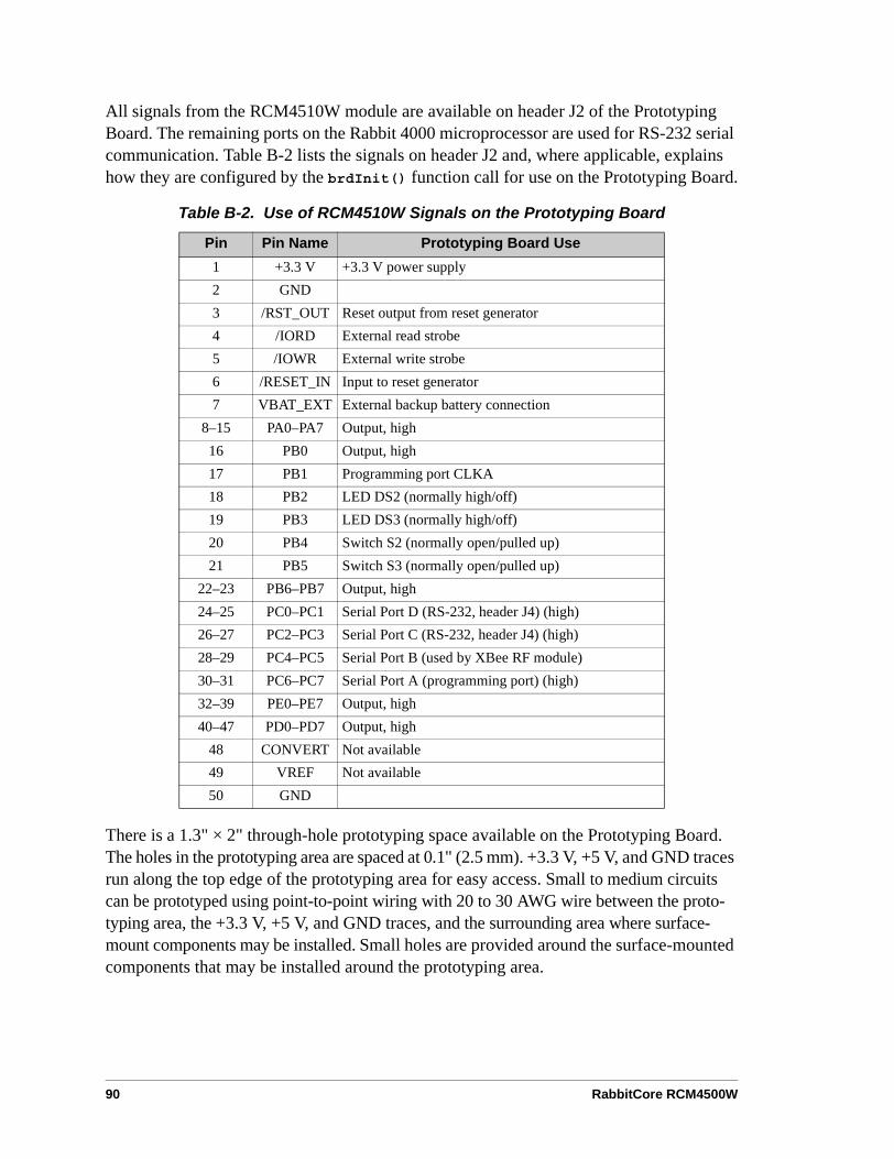
90 RabbitCore RCM4500W
All signals from the RCM4510W module are available on header J2 of the Prototyping Board. The remaining ports on the Rabbit 4000 microprocessor are used for RS-232 serial communication. Table B-2 lists the signals on header J2 and, where applicable, explains how they are configured by the brdInit() function call for use on the Prototyping Board.
There is a 1.3" × 2" through-hole prototyping space available on the Prototyping Board. The holes in the prototyping area are spaced at 0.1" (2.5 mm). +3.3 V, +5 V, and GND traces run along the top edge of the prototyping area for easy access. Small to medium circuits can be prototyped using point-to-point wiring with 20 to 30 AWG wire between the proto-typing area, the +3.3 V, +5 V, and GND traces, and the surrounding area where surface-mount components may be installed. Small holes are provided around the surface-mounted components that may be installed around the prototyping area.
Table B-2. Use of RCM4510W Signals on the Prototyping Board
Pin Pin Name Prototyping Board Use1 +3.3 V +3.3 V power supply2 GND3 /RST_OUT Reset output from reset generator4 /IORD External read strobe5 /IOWR External write strobe6 /RESET_IN Input to reset generator7 VBAT_EXT External backup battery connection
8–15 PA0–PA7 Output, high16 PB0 Output, high17 PB1 Programming port CLKA18 PB2 LED DS2 (normally high/off)19 PB3 LED DS3 (normally high/off)20 PB4 Switch S2 (normally open/pulled up)21 PB5 Switch S3 (normally open/pulled up)
22–23 PB6–PB7 Output, high24–25 PC0–PC1 Serial Port D (RS-232, header J4) (high)26–27 PC2–PC3 Serial Port C (RS-232, header J4) (high)28–29 PC4–PC5 Serial Port B (used by XBee RF module)30–31 PC6–PC7 Serial Port A (programming port) (high)32–39 PE0–PE7 Output, high40–47 PD0–PD7 Output, high
48 CONVERT Not available49 VREF Not available50 GND

User’s Manual 91
B.4.1 Adding Other Components
There are pads for 28-pin TSSOP devices, 16-pin SOIC devices, and 6-pin SOT devices that can be used for surface-mount prototyping with these devices. There are also pads that can be used for SMT resistors and capacitors in an 0805 SMT package. Each component has every one of its pin pads connected to a hole in which a 30 AWG wire can be soldered (standard wire wrap wire can be soldered in for point-to-point wiring on the Prototyping Board). Because the traces are very thin, carefully determine which set of holes is con-nected to which surface-mount pad.
B.4.2 Measuring Current Draw
The Prototyping Board has a current-measurement feature available at header locations JP1 and JP2 for the +5 V and +3.3 V supplies respectively. To measure current, you will have to cut the trace on the bottom side of the Prototyping Board corresponding to the power supply or power supplies whose current draw you will be measuring. Header loca-tions JP1 and JP2 are shown in Figure B-5. Then install a 1 × 2 header strip from the Development Kit on the top side of the Prototyping Board at the header location(s) whose trace(s) you cut. The header strip(s) will allow you to use an ammeter across their pins to measure the current drawn from that supply. Once you are done measuring the current, place a jumper across the header pins to resume normal operation.
Figure B-5. Prototyping Board Current-Measurement Option
NOTE: Once you have cut the trace below header location JP1 or JP2, you must either be using the ammeter or have a jumper in place in order for power to be delivered to the Prototyping Board.
!
$!!*
> !?)/
> !?
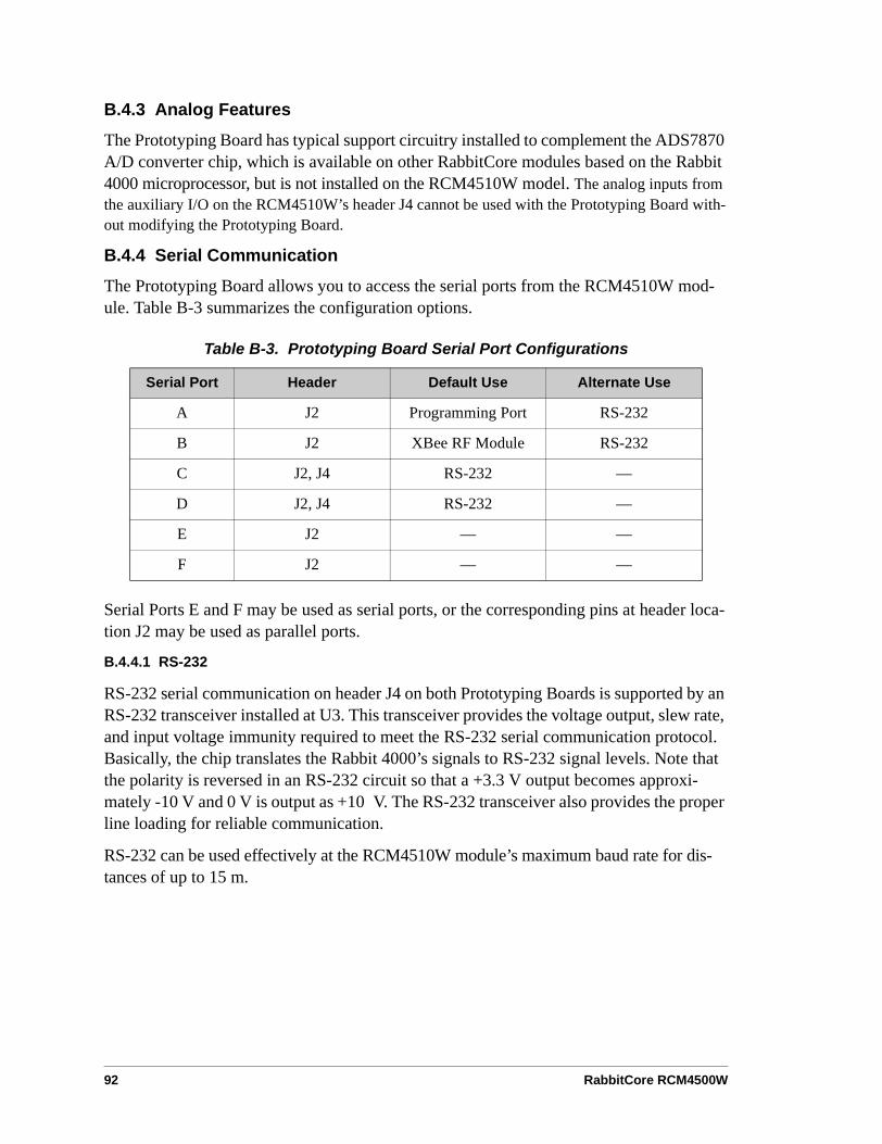
92 RabbitCore RCM4500W
B.4.3 Analog Features
The Prototyping Board has typical support circuitry installed to complement the ADS7870 A/D converter chip, which is available on other RabbitCore modules based on the Rabbit 4000 microprocessor, but is not installed on the RCM4510W model. The analog inputs from the auxiliary I/O on the RCM4510W’s header J4 cannot be used with the Prototyping Board with-out modifying the Prototyping Board.
B.4.4 Serial Communication
The Prototyping Board allows you to access the serial ports from the RCM4510W mod-ule. Table B-3 summarizes the configuration options.
Serial Ports E and F may be used as serial ports, or the corresponding pins at header loca-tion J2 may be used as parallel ports.
B.4.4.1 RS-232
RS-232 serial communication on header J4 on both Prototyping Boards is supported by an RS-232 transceiver installed at U3. This transceiver provides the voltage output, slew rate, and input voltage immunity required to meet the RS-232 serial communication protocol. Basically, the chip translates the Rabbit 4000’s signals to RS-232 signal levels. Note that the polarity is reversed in an RS-232 circuit so that a +3.3 V output becomes approxi-mately -10 V and 0 V is output as +10 V. The RS-232 transceiver also provides the proper line loading for reliable communication.
RS-232 can be used effectively at the RCM4510W module’s maximum baud rate for dis-tances of up to 15 m.
Table B-3. Prototyping Board Serial Port Configurations
Serial Port Header Default Use Alternate Use
A J2 Programming Port RS-232
B J2 XBee RF Module RS-232
C J2, J4 RS-232 —
D J2, J4 RS-232 —
E J2 — —
F J2 — —

User’s Manual 93
RS-232 flow control on an RS-232 port is initiated in software using the serXflowcon-trolOn function call from RS232.LIB, where X is the serial port (C or D). The locations of the flow control lines are specified using a set of five macros.
SERX_RTS_PORT—Data register for the parallel port that the RTS line is on (e.g., PCDR).
SERA_RTS_SHADOW—Shadow register for the RTS line's parallel port (e.g., PCDRShadow).
SERA_RTS_BIT—The bit number for the RTS line.
SERA_CTS_PORT—Data register for the parallel port that the CTS line is on (e.g., PCDRShadow).
SERA_CTS_BIT—The bit number for the CTS line.
Standard 3-wire RS-232 communication using Serial Ports C and D is illustrated in the following sample code.
#define CINBUFSIZE 15 // set size of circular buffers in bytes#define COUTBUFSIZE 15
#define DINBUFSIZE 15#define DOUTBUFSIZE 15
#define MYBAUD 115200 // set baud rate#endif
main() serCopen(_MYBAUD); // open Serial Ports C and D serDopen(_MYBAUD); serCwrFlush(); // flush their input and transmit buffers serCrdFlush(); serDwrFlush(); serDrdFlush(); serCclose(_MYBAUD); // close Serial Ports C and D serDclose(_MYBAUD);

94 RabbitCore RCM4500W
B.5 Prototyping Board Jumper ConfigurationsFigure B-6 shows the header locations used to configure the various Prototyping Board options via jumpers.
Figure B-6. Location of Configurable Jumpers on Prototyping Board
Table B-4 lists the configuration options using either jumpers or 0 Ω surface-mount resistors.
Table B-4. RCM4510W Prototyping Board Jumper Configurations
Header Description Pins Connected Factory Default
JP1 +5 V Current Measurement 1–2 Via trace or jumper Connected
JP2 +3.3 V Current Measurement 1–2 Via trace or jumper Connected
JP3JP4 PC0/TxD/LED DS2
JP31–2 TxD on header J4 ×JP41–2 PC0 to LED DS2
n.c. PC0 available on header J2

User’s Manual 95
JP5JP6 PC1/RxD/Switch S2
JP51–2 RxD on header J4 ×JP61–2 PC1 to Switch S2
n.c. PC1 available on header J2
JP7JP8 PC2/TxC/LED DS3
JP71–2 TxC on header J4 ×JP61–2 PC2 to LED DS3
n.c. PC2 available on header J2
JP9JP10 PC3/RxC/Switch S3
JP91–2 PC3 to Switch S3
JP101–2 RxC on header J4 ×n.c. PC3 available on header J2
JP11 LN0 buffer/filter to RCM4510W 1–2 Connected
JP12 PB2/LED DS21–2 Connected: PB2 to LED DS2 ×n.c. PB2 available on header J2
JP13 LN1 buffer/filter to RCM4510W 1–2 Connected
JP14 PB3/LED DS31–2 Connected: PB3 to LED DS3 ×n.c. PB3 available on header J2
JP15 LN2 buffer/filter to RCM4510W 1–2 Connected
JP16 PB4/Switch S21–2 Connected: PB4 to Switch S2 ×n.c. PB4 available on header J2
JP17 LN3 buffer/filter to RCM4510W 1–2 Connected
JP18 PB5/Switch S31–2 Connected: PB5 to Switch S3 ×n.c. PB5 available on header J2
JP19 LN4 buffer/filter to RCM4510W 1–2 Connected
Table B-4. RCM4510W Prototyping Board Jumper Configurations (continued)
Header Description Pins Connected Factory Default

96 RabbitCore RCM4500W
NOTE: Jumper connections JP3–JP10, JP12, JP14, JP16, JP18, JP23, and JP24 are made using 0 Ω surface-mounted resistors. Jumper connections JP11, JP13, JP15, JP17, and JP19–JP22 are made using 470 Ω surface-mounted resistors.
JP20 LN5 buffer/filter to RCM4510W 1–2 Connected
JP21 LN6 buffer/filter to RCM4510W 1–2 Connected
JP22 LN7 buffer/filter to RCM4510W 1–2 Connected
JP23 LN4_IN–LN6_IN1–2 Tied to analog ground ×2–3 Tied to VREF
JP24 LN0_IN–LN3_IN1–2 Tied to analog ground ×2–3 Tied to VREF
JP25 Thermistor Location 1–2 n.c.
Table B-4. RCM4510W Prototyping Board Jumper Configurations (continued)
Header Description Pins Connected Factory Default

User’s Manual 97
APPENDIX C. POWER SUPPLY
Appendix C provides information on the current requirements ofthe RCM4510W, and includes some background on the chipselect circuit used in power management.
C.1 Power SuppliesThe RCM4510W requires a regulated 3.3 V DC ±5% power source. The RabbitCore design presumes that the voltage regulator is on the user board, and that the power is made available to the RCM4510W board through header J1.
An RCM4510W with no loading at the outputs operating at 29.48 MHz typically draws 80 mA, and may draw up to 150 mA while the XBee RF module is transmitting or receiving.
C.1.1 Battery Backup
The RCM4510W does not have a battery, but there is provision for a customer-supplied battery to back up the data SRAM and keep the internal Rabbit 4000 real-time clock running.
Header J1, shown in Figure C-1, allows access to the external battery. This header makes it possible to connect an external 3 V power supply. This allows the SRAM and the inter-nal Rabbit 4000 real-time clock to retain data with the RCM4510W powered down.
Figure C-1. External Battery Connections at Header J1
A lithium battery with a nominal voltage of 3 V and a minimum capacity of 165 mA·h is recommended. A lithium battery is strongly recommended because of its nearly constant nominal voltage over most of its life.
!"$#
#9-'/23,"3--'/J
/
!$

98 RabbitCore RCM4500W
The drain on the battery by the RCM4510W is typically 7.5 µA when no other power is supplied. If a 165 mA·h battery is used, the battery can last about 2.5 years:
The actual battery life in your application will depend on the current drawn by components not on the RCM4510W and on the storage capacity of the battery. The RCM4510W does not drain the battery while it is powered up normally.
Cycle the main power off/on after you install a backup battery for the first time, and when-ever you replace the battery. This step will minimize the current drawn by the real-time clock oscillator circuit from the backup battery should the RCM4510W experience a loss of main power.
NOTE: Remember to cycle the main power off/on any time the RCM4510W is removed from the Prototyping Board or motherboard since that is where the backup battery would be located.
Rabbit’s Technical Note TN235, External 32.768 kHz Oscillator Circuits, provides addi-tional information about the current draw by the real-time clock oscillator circuit.
C.1.2 Battery-Backup Circuit
Figure C-2 shows the battery-backup circuit.
Figure C-2. RCM4510W Backup Battery Circuit
The battery-backup circuit serves three purposes:
• It reduces the battery voltage to the SRAM and to the real-time clock, thereby limiting the current consumed by the real-time clock and lengthening the battery life.
• It ensures that current can flow only out of the battery to prevent charging the battery.
• A voltage, VOSC, is supplied to U11, which keeps the 32.768 kHz oscillator working when the voltage begins to drop.
C.1.3 Reset Generator
The RCM4510W uses a reset generator to reset the Rabbit 4000 microprocessor when the voltage drops below the voltage necessary for reliable operation. The reset occurs between
165 mA·h7.5 µA
------------------------ 2.5 years.=
!
K
!"=#
'(
K
!
2&
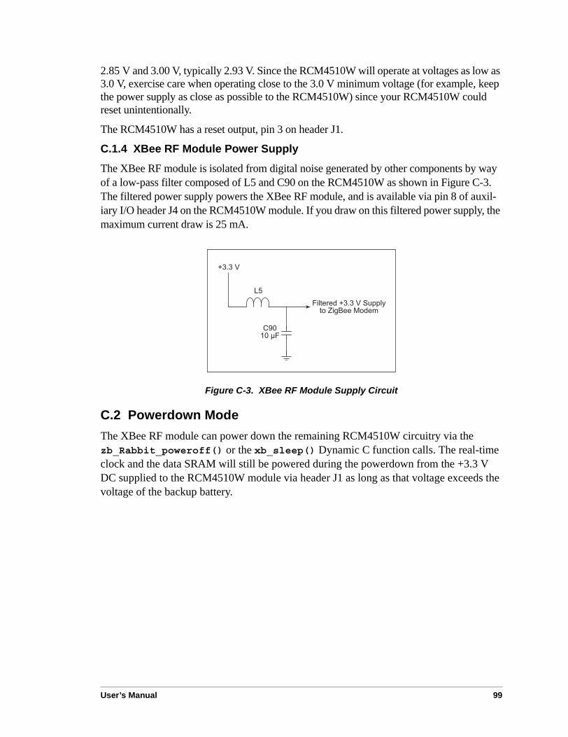
User’s Manual 99
2.85 V and 3.00 V, typically 2.93 V. Since the RCM4510W will operate at voltages as low as 3.0 V, exercise care when operating close to the 3.0 V minimum voltage (for example, keep the power supply as close as possible to the RCM4510W) since your RCM4510W could reset unintentionally.
The RCM4510W has a reset output, pin 3 on header J1.
C.1.4 XBee RF Module Power Supply
The XBee RF module is isolated from digital noise generated by other components by way of a low-pass filter composed of L5 and C90 on the RCM4510W as shown in Figure C-3. The filtered power supply powers the XBee RF module, and is available via pin 8 of auxil-iary I/O header J4 on the RCM4510W module. If you draw on this filtered power supply, the maximum current draw is 25 mA.
Figure C-3. XBee RF Module Supply Circuit
C.2 Powerdown ModeThe XBee RF module can power down the remaining RCM4510W circuitry via the zb_Rabbit_poweroff() or the xb_sleep() Dynamic C function calls. The real-time clock and the data SRAM will still be powered during the powerdown from the +3.3 V DC supplied to the RCM4510W module via header J1 as long as that voltage exceeds the voltage of the backup battery.
!
L&
&1,-'/'8 ! 655,J-) H17"'' )8'(

100 RabbitCore RCM4500W

User’s Manual 101
APPENDIX D. ADDITIONALCONFIGURATION INSTRUCTIONS
Appendix D provides information on how to find the latest firm-ware for the XBee RF module and the Digi® XBee USB used asthe ZigBee coordinator, and how to install the firmware.
D.1 XBee RF Module Firmware DownloadsBy default, the RCM4510W is shipped from the factory with firmware to operate as either a router or as an end device in a mesh network. You will need to run the MODEMFWLOAD.C sample program in the Dynamic C SAMPLES\RCM4500W\XBee folder to download the firmware needed to operate the RCM4510W as a coordinator.
NOTE: You can verify the firmware version by running the AT_INTERACTIVE.C sam-ple program in the Dynamic C SAMPLES\XBEE folder and by entering the command ATVR <Enter> to get the version number displayed in the Dynamic C STDIO window.
CAUTION: Different firmware versions are likely to interact with the Dynamic C librar-ies in different ways. Rabbit has tested the firmware associated with a particular version of Dynamic C for correct operation, and only this version is included on the Dynamic C CD-ROM — do not use any other firmware versions with that version of Dynamic C.
Once you have successfully loaded the firmware, compile and run another sample program to make sure the MODEMFWLOAD.C sample program does not inadvertently reload (or partially reload) the firmware.
If you are uploading firmware because you upgraded to a more recent Dynamic C release, remember to recompile your applications using the new version of Dynamic C once you have uploaded the new firmware.
D.1.1 Dynamic C v. 10.44 and Later
Encrypted libraries have been created within Dynamic C for the firmware. The three ZigBee PRO libraries are in the LIB\Rabbit4000\XBee\XBee_Firmware\ZigBee folder.
• A Dynamic C library of the type XB24-ZB_21….LIB is used for a coordinator RCM4510W.
• A Dynamic C library of the type XB24-ZB_23….LIB is used for a router RCM4510W.
• A Dynamic C library of the type XB24-ZB_29….LIB is used for an end-device RCM4510W.
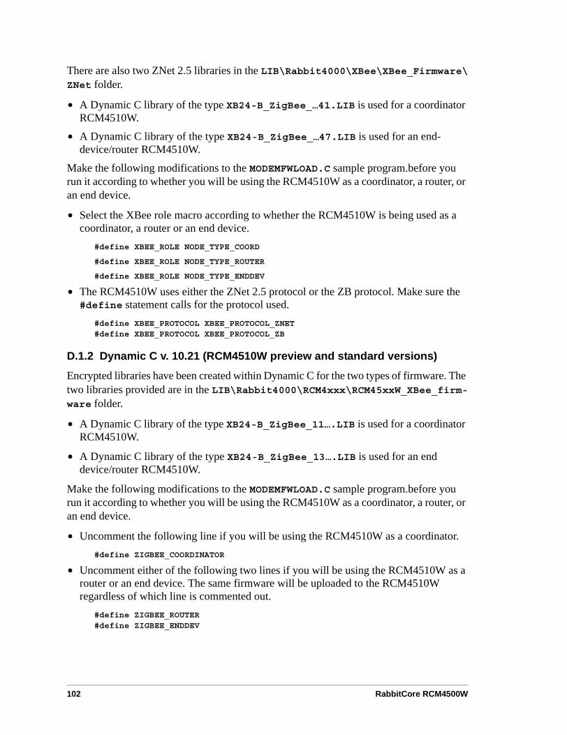
102 RabbitCore RCM4500W
There are also two ZNet 2.5 libraries in the LIB\Rabbit4000\XBee\XBee_Firmware\ZNet folder.
• A Dynamic C library of the type XB24-B_ZigBee_…41.LIB is used for a coordinator RCM4510W.
• A Dynamic C library of the type XB24-B_ZigBee_…47.LIB is used for an end-device/router RCM4510W.
Make the following modifications to the MODEMFWLOAD.C sample program.before you run it according to whether you will be using the RCM4510W as a coordinator, a router, or an end device.
• Select the XBee role macro according to whether the RCM4510W is being used as a coordinator, a router or an end device.
#define XBEE_ROLE NODE_TYPE_COORD
#define XBEE_ROLE NODE_TYPE_ROUTER
#define XBEE_ROLE NODE_TYPE_ENDDEV
• The RCM4510W uses either the ZNet 2.5 protocol or the ZB protocol. Make sure the #define statement calls for the protocol used.
#define XBEE_PROTOCOL XBEE_PROTOCOL_ZNET#define XBEE_PROTOCOL XBEE_PROTOCOL_ZB
D.1.2 Dynamic C v. 10.21 (RCM4510W preview and standard versions)
Encrypted libraries have been created within Dynamic C for the two types of firmware. The two libraries provided are in the LIB\Rabbit4000\RCM4xxx\RCM45xxW_XBee_firm-ware folder.
• A Dynamic C library of the type XB24-B_ZigBee_11….LIB is used for a coordinator RCM4510W.
• A Dynamic C library of the type XB24-B_ZigBee_13….LIB is used for an end device/router RCM4510W.
Make the following modifications to the MODEMFWLOAD.C sample program.before you run it according to whether you will be using the RCM4510W as a coordinator, a router, or an end device.
• Uncomment the following line if you will be using the RCM4510W as a coordinator.#define ZIGBEE_COORDINATOR
• Uncomment either of the following two lines if you will be using the RCM4510W as a router or an end device. The same firmware will be uploaded to the RCM4510W regardless of which line is commented out.
#define ZIGBEE_ROUTER#define ZIGBEE_ENDDEV

User’s Manual 103
D.1.3 Dynamic C v. 10.11 (RCM4510W preview version only)
The coordinator and end-device/router firmware is provided in the Dynamic C SAMPLES\RCM4500W\MODEMFW folder.
• Firmware of the type XB24-B_ZigBee_11….ebl is used for a coordinator RCM4510W.
• Firmware of the type XB24-B_ZigBee_13….ebl is used for an end device/router RCM4510W.
When you use the bootloader function, you will have to provide a file read function that supplies the binary image in record sizes specified by the xmodem protocol. The read func-tion will have the following prototype.
char *fileread(int recordNumber, int recordSize)
The function will return the address of a buffer containing the data. A NULL return signifies the end of the file.
Before you compile and run this sample program, modify the ximport statement to point to the binary image file you will be downloading.
#ximport "MODEMFW/Coordinator/XB24-B_ZigBee_1118.ebl" zb_ebl_file
In this example, the XB24-B_ZigBee_1118.ebl file is in the Dynamic C SAMPLES\RCM4500W\MODEMFW\Coordinator folder. If you downloaded a firmware update to another location on your hard drive, you would change the directory path accordingly as in the following example.
#ximport "/temp/XB24-B_ZigBee_1118.ebl" zb_ebl_file
To see the details of what is happening while the sample program runs, you should #define the following.
#define ZB_VERBOSE#define XMODEM_DEBUG
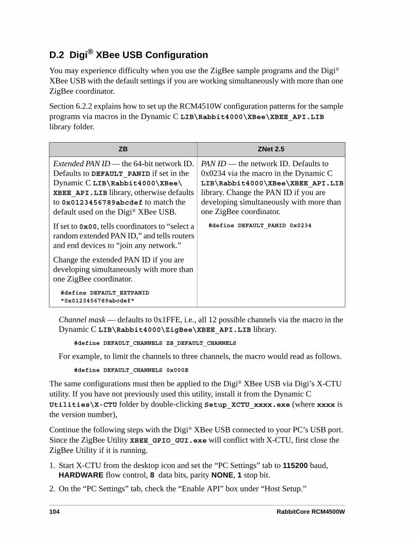
104 RabbitCore RCM4500W
D.2 Digi® XBee USB ConfigurationYou may experience difficulty when you use the ZigBee sample programs and the Digi® XBee USB with the default settings if you are working simultaneously with more than one ZigBee coordinator.
Section 6.2.2 explains how to set up the RCM4510W configuration patterns for the sample programs via macros in the Dynamic C LIB\Rabbit4000\XBee\XBEE_API.LIB library folder.
Channel mask — defaults to 0x1FFE, i.e., all 12 possible channels via the macro in the Dynamic C LIB\Rabbit4000\ZigBee\XBEE_API.LIB library.
#define DEFAULT_CHANNELS ZB_DEFAULT_CHANNELS
For example, to limit the channels to three channels, the macro would read as follows.#define DEFAULT_CHANNELS 0x000E
The same configurations must then be applied to the Digi® XBee USB via Digi’s X-CTU utility. If you have not previously used this utility, install it from the Dynamic C Utilities\X-CTU folder by double-clicking Setup_XCTU_xxxx.exe (where xxxx is the version number),
Continue the following steps with the Digi® XBee USB connected to your PC’s USB port. Since the ZigBee Utility XBEE_GPIO_GUI.exe will conflict with X-CTU, first close the ZigBee Utility if it is running.
1. Start X-CTU from the desktop icon and set the “PC Settings” tab to 115200 baud, HARDWARE flow control, 8 data bits, parity NONE, 1 stop bit.
2. On the “PC Settings” tab, check the “Enable API” box under “Host Setup.”
ZB ZNet 2.5
Extended PAN ID — the 64-bit network ID. Defaults to DEFAULT_PANID if set in the Dynamic C LIB\Rabbit4000\XBee\XBEE_API.LIB library, otherwise defaults to 0x0123456789abcdef to match the default used on the Digi® XBee USB.
If set to 0x00, tells coordinators to “select a random extended PAN ID,” and tells routers and end devices to “join any network.”
Change the extended PAN ID if you are developing simultaneously with more than one ZigBee coordinator.
#define DEFAULT_EXTPANID "0x0123456789abcdef"
PAN ID — the network ID. Defaults to 0x0234 via the macro in the Dynamic C LIB\Rabbit4000\XBee\XBEE_API.LIB library. Change the PAN ID if you are developing simultaneously with more than one ZigBee coordinator.#define DEFAULT_PANID 0x0234

User’s Manual 105
3. On the “PC Settings” tab, select the “USB Serial Port” corresponding to the USB serial port the Digi® XBee USB is connected to and click “Test/Query.” You should see a response showing the Modem Type (XB 24-B) and the firmware version. Click OK.
Note that several USB serial ports could be listed. If you select a serial port without the Digi® XBee USB connected, the X-CTU response to “Test/Query.” will be “communi-cation with modem … OK,” but the modem type will be unknown, and the firmware version will be blank.
If you a get a message that X-CTU is unable to open the COM port, verify that you selected the COM port with the “USB Serial Port,” then try unplugging the Digi® XBee USB from the USB slot and plugging it back in. Now click “Test/Query” again.
4. Under the “Modem Configuration” tab click the “Read” button. X-CTU will now display the networking and I/O parameters for the Digi® XBee USB being used as the ZigBee coordinator.
Modem: XBEE XB24-ZB
Function Set: ZIGBEE COORDINATOR API (do not select other settings)
Version: the version of the firmware included with the version of Dynamic C you are using (should be of the type 21…)
5. Now set the networking parameters in your project defines or in the sample program to match the parameters in the Dynamic C LIB\Rabbit4000\XBee\XBEE_API.LIB library.
6. Now set the networking parameters in your project defines or in the sample program to match the parameters in the Dynamic C LIB\Rabbit4000\XBee\XBEE_API.LIB library.
Networking
(D) CH - Operating Channel — this is the operating channel you could see when you ran the AT_INTERACTIVE.C sample program in the Dynamic C SAMPLES\XBEE folder by enter-ing the command ATCH <Enter>. This channel information cannot be changed from the X-CTU utility.
(0123456789ABCDEF) ID - Extended Pan ID — set the new extended PAN ID that follows 0x to match the DEFAULT_EXTPANID macro.
(1FFE) SC - Scan Channels - set the new value for the channels to scan, E, for example, to match the new setting in the macro.
#define DEFAULT_CHANNELS 0x000E
7. Finish by clicking the “Write” button.
We are including a profile file (XBee-USB ZB defaults.pro) in the Utilities/X-CTU folder to load a Digi® XBee USB with default settings. Once the Digi® XBee USB is con-nected to an available USB port on your PC, start the X-CTU utility. Click the “Load” button in the Profile section, navigate to the .pro file, and it will set all of the defaults. Then click the “Write” button to write the settings to the Digi® XBee USB.

106 RabbitCore RCM4500W
D.2.1 Additional Reference Information
Check Digi’s Web site for the latest information and documentation on the XBee RF module, the X-CTU utility, and the Digi® XBee USB. Note that the XBee® and the XBee PRO® RF modules are presently not compatible with the XBeeRF module used with the RCM4510W, but the general documentation about ZigBee and the use of AT commands for the XBee® and the XBee PRO® RF modules is relevant.
D.2.2 Update Digi® XBee USB Firmware
The firmware version used by the Digi® XBee USB must correspond to the firmware version installed on the RCM4510W. If you have updated the RCM4510W firmware (or you have a need to re-install the firmware on the Digi® XBee USB), the corresponding firmware for the Digi® XBee USB is in the Dynamic C Utilities\X-CTU\MODEMFW folder.
• Remember to record the extended PAN ID, NI, and other parameters you are using.• Firmware of the type XB24-ZB_21….zip is used for the Digi® XBee USB coordinator.
CAUTION: Different firmware versions are likely to interact with the Dynamic C libraries in different ways. Rabbit has tested the firmware associated with a particular version of Dynamic C for correct operation, and only this version is included on the Dynamic C CD-ROM — do not use any other firmware versions with that version of Dynamic C.
1. Start X-CTU from the desktop icon and set the “PC Settings” tab to 9600 baud, HARD-WARE flow control, 8 data bits, parity NONE, 1 stop bit.
2. On the “PC Settings” tab, check the “Enable API” box under “Host Setup.”
3. On the “PC Settings” tab, select the “USB Serial Port” and click “Test/Query.” You should see a response showing the Modem Type (XB 24 B) and the firmware version. Click OK.
Note that several USB serial ports could be listed. If you select a serial port without the Digi® XBee USB connected, the X-CTU response to “Test/Query.” will be “communi-cation with modem … OK,” but the modem type will be unknown, and the firmware version will be blank.
If you a get a message that X-CTU is unable to open the COM port, verify that you selected the COM port with the “USB Serial Port,” then try unplugging the Digi® XBee USB from the USB slot and plugging it back in. Now click “Test/Query” again.
4. Under the “Modem Configuration” tab click the “Read” button. X-CTU will now dis-play the networking and I/O parameters for the Digi® XBee USB.
Modem: XBEE XB24-ZB
Function Set: ZIGBEE COORDINATOR API (do not select other settings)
Version: the version of the firmware included with the version of Dynamic C you are using
5. Click the “Read” button, select XB24-B as the Modem type; select ZIGBEE COORDI-NATOR API as the Function Set, and 21… as the Version, then click “Write.”
6. When the process is complete set the PANID, NI, and other parameters to the values you were using before the firmware was upgraded.
User’s Manual 107
INDEX
Aadditional information
online documentation .......... 7analog inputs
function callszb_adc_in() .................... 55
Bbattery backup
battery life ......................... 98circuit ................................ 98external battery connec-
tions .............................. 97real-time clock .................. 98reset generator ................... 98use of battery-backed SRAM
....................................... 48board initialization
function calls ..................... 50brdInit() ......................... 50
bus loading ............................ 77
Cclock doubler ........................ 42cloning .................................. 48
include firmware upgrade in cloned application ......... 49
configurationDigi® XBee USB (ZigBee
coordinator) ................ 104conformal coating ................. 80
DDevelopment Kit ..................... 5
AC adapter .......................... 5Getting Started instructions 5programming cable ............. 5
Digi® XBee USB (ZigBee coor-dinator)
configuration ................... 104uploading new firmware . 106
digital I/O .............................. 26function calls ..................... 47
digInAlert() ................... 51timedAlert() ................... 51zb_dio_in() .................... 54zb_dio_out() .................. 54zb_io_init() .................... 52
I/O buffer sourcing and sink-ing limits ....................... 77
memory interface .............. 33SMODE0 .................... 33, 36SMODE1 .................... 33, 36
dimensionsPrototyping Board ............. 87RCM4510W ...................... 70
Dynamic C .............. 6, 9, 14, 45add-on modules ............. 9, 56
installation ....................... 9battery-backed SRAM ...... 48libraries
RCM45xxW.LIB .......... 50protected variables ............ 48Rabbit Embedded Security
Pack .......................... 6, 56sample programs ............... 18standard features
debugging ...................... 46telephone-based technical
support ...................... 6, 56upgrades and patches ........ 56version compatibility .......... 6
Eexclusion zone ...................... 71external I/O bus .................... 33
Ffeatures .................................... 2
Prototyping Boards ..... 84, 85
firmware downloadDigi® XBee USB ........... 106
firmware updates ......... 106via cloned application ....... 49XBee RF module ............ 101
coordinator vs. end device/router ................ 102, 103
firmware updates . 101, 106flash memory addresses
user blocks ........................ 43
Hhardware connections
install RCM4510W on Proto-typing Board ................. 11
power supply ..................... 13programming cable ........... 12
II/O buffer sourcing and sinking
limits ............................. 77
Jjumper configurations
Prototyping Board ............. 94JP1 (+5 V current measure-
ment) .......................... 94JP1 (LN0 buffer/filter to
RCM4510W) .............. 95JP12 (PB2/LED DS2) ... 95JP13 (LN1 buffer/filter to
RCM4510W) .............. 95JP14 (PB3/LED DS3) ... 95JP15 (LN2 buffer/filter to
RCM4510W) .............. 95JP16 (PB4/Switch S2) ... 95JP17 (LN3 buffer/filter to
RCM4510W) .............. 95JP18 (PB5/Switch S2) ... 95
108 RabbitCore RCM4500W
jumper configurationsPrototyping Board (continued)
JP19 (LN4 buffer/filter to RCM4510W) ..............95
JP2 (+ 3.3 V current mea-surement) ....................94
JP20 (LN5 buffer/filter to RCM4510W) ..............96
JP21 (LN6 buffer/filter to RCM4510W) ..............96
JP22 (LN7 buffer/filter to RCM4510W) ..............96
JP23 (analog inputs LN4–LN6 configuration) .....96
JP24 (analog inputs LN0–LN3 configuration) .....96
JP3–JP4 (PC0/TxD/LED DS2) ............................94
JP5–JP6 (PC1/RxD/Switch S2) ...............................95
JP7–JP8 (PC2/TxC/LED DS3) ............................95
JP9–JP10 (PC3/RxC/Switch S3) ..................95
RCM4510W ......................81JP1 (LN0 or PD0 on J1) 81JP10 (PE5 or SMODE0
output on J1) ...............81JP11 (PE6 or SMODE1
output on J1) ...............81JP12 (PE7 or STATUS
output on J1) ...............81JP2 (LN2 or PD2 on J1) 82JP2 (LN6 or PD6 on J1) 82JP4 (LN7 or PD7 on J1) 82JP5 (LN5 or PD5 on J1) 82JP6 (LN4 or PD4 on J1) 82JP7 (LN3 or PD3 on J1) 82JP9 (LN1 or PD1 on J1) 82jumper locations ............81
Oonchip-encryption RAM
how to use ..........................19options .....................................7
Mesh Network Add-On Kit .7
Ppinout
Prototyping Board .............89RCM4510W
alternate configurations .28RCM4510W headers .........26
power supplies+3.3 V ................................97battery backup ...................97
Program Mode .......................37switching modes ................37
programming cablePROG connector ...............37RCM4510W connections ..12
programming port .................36Prototyping Board .................84
access to RCM4510W analog inputs .............................86
adding components ............91dimensions .........................87expansion area ...................85features ........................84, 85jumper configurations .......94jumper locations ................94mounting RCM4510W ......11pinout .................................89power supply .....................88prototyping area ................90specifications .....................88use of Rabbit 4000 signals 90
RRabbit 4000
spectrum spreader time delays .......................................79
Rabbit subsystems .................27RCM4510W
mounting on Prototyping Board .............................11
real-time clockbattery backup ...................98
Run Mode ..............................37switching modes ................37
Ssample programs .............18, 59
getting to know the RCM4510WCONTROLLED.C .........18FLASHLED1.C .............18FLASHLED2.C .............18TAMPERDETECTION.C
.....................................19TOGGLESWITCH.C ....19
PONG.C ............................14real-time clock
RTC_TEST.C ................23SETRTCKB.C ...............23
sample programs (continued)serial communication
FLOWCONTROL.C .....20IOCONFIG_
SWITCHECHO.C ......22PARITY.C .....................20SERDMA.C ...................20SIMPLE3WIRE.C .........21SIMPLE5WIRE.C .........21SWITCHCHAR.C .........21
sleep mode .........................66USERBLOCK_CLEAR.C 47USERBLOCK_INFO.C ....47XBee RF module
AT_INTERACTIVE.C ...............15, 62, 101, 105
AT_RUNONCE.C .........62MODEMFWLOAD.C
...........................101, 102SLEEPMODE.C ............63SLEEPMODE2.C ..........64XBEE_GPIO_SERVER.C
...............................59, 64ZigBee setup ......................59
serial communication ............34function calls .....................47Prototyping Board
RS-232 ...........................92software
PACKET.LIB ................47RS232.LIB .....................47
serial ports .............................34programming port ..............36receive line not pulled up ..35Serial Port B (XBee RF
module) .........................34Serial Port E
configuration informa-tion ........................22, 34
Serial Port Fconfiguration informa-
tion ........................22, 34sleep mode .............................65
sample programs ...............66ST setting ..........................65xb_sleep() ....................65, 66xb_tick() ............................66zb_Rabbit_poweroff() .......66

User’s Manual 109
software ................................... 6external I/O bus ........... 33, 47I/O drivers ......................... 47libraries
RCM45xxW.LIB .......... 52serial communication drivers
....................................... 47version compatibility .......... 6ZigBee drivers ................... 49
specificationsbus loading ........................ 77digital I/O buffer sourcing and
sinking limits ................ 77exclusion zone ................... 71header footprint ................. 75Prototyping Board ............. 88Rabbit 4000 DC characteris-
tics ................................. 76Rabbit 4000 timing diagram
....................................... 78RCM4510W ...................... 69
dimensions .................... 70electrical, mechanical, and
environmental ............. 72relative pin 1 locations ...... 75XBee RF module .............. 74
spectrum spreader ................. 79settings .............................. 42
subsystemsdigital inputs and outputs .. 26
switching modes ................... 37
Ttechnical support ................... 16
Uuser block
determining size ................ 47function calls ..................... 47
readUserBlock() ............ 43writeUserBlock() ........... 43
reserved area for calibration constants ....................... 47
XXBee firmware ....................... 6
upgrading to ZB ................ 58ZB ................................. 6, 58Znet 2.5 ......................... 6, 58Znet 2.5 vs. ZB ................. 58
XBee RF moduleadditional resources .......... 67firmware download ......... 101function calls
xb_sleep() ...................... 99zb_Rabbit_poweroff() ... 99
ZZigBee
software libraries .............. 49ZigBee protocol
coordinator ........................ 57end device ......................... 57introduction ....................... 57mesh network .................... 57router ................................. 57

110 RabbitCore RCM4500W

User’s Manual 111
SCHEMATICS
090-0242 RCM4500W Schematic (preview version)www.rabbit.com/documentation/schemat/090-0242.pdf
090-0246 RCM4500W Schematic (standard release)www.rabbit.com/documentation/schemat/090-0246.pdf
090-0230 Prototyping Board Schematicwww.rabbit.com/documentation/schemat/090-0230.pdf
090-0128 Programming Cable Schematicwww.rabbit.com/documentation/schemat/090-0128.pdf
090-0252 USB Programming Cable Schematicwww.rabbit.com/documentation/schemat/090-0252.pdf
You may use the URL information provided above to access the latest schematics directly.


Mouser Electronics
Authorized Distributor
Click to View Pricing, Inventory, Delivery & Lifecycle Information: Rabbit Semiconductor:
101-1272


