User manual - Instramedinstramed.com.br/languages/eng/assets/cardiomax-user-manual-eng.pdf · User...
167
User manual Cardioverter/Biphasic Defibrillator Monitor
Transcript of User manual - Instramedinstramed.com.br/languages/eng/assets/cardiomax-user-manual-eng.pdf · User...

User manual
Cardioverter/Biphasic Defibrillator Monitor

Instramed Indústria Médico Hospitalar Ltda.Industrial unity:
Rua Beco José Paris, 339 – Pavilhão 19 Postal code: 91140-310 Porto Alegre – RS, Brasil Phone/fax number: (51) 3073 8200 E-mail: [email protected] Website: www.instramed.com.br
European representative:Obelis S.A.
Bd. Général Wahis 53, 1030, Brussels - Belgium Phone. : + 32.2.732.59.54 Fax : + 32.2.732.60.03
E-mail : [email protected]
ATTENTION: Instramed assumes no responsibility for any damage caused to individuals or property brought by failure to use this product in accordance with the information, recommendations and warnings presented in the user manual, alterations made in the device, attempts of repair not provided by authorized technical assistance centers, operation by unqualified personnel, use of defective device or use of accessories and parts not supplied by the manufacturer.
For information about warranty or technical assistance, please contact Instramed’s technical support.Copyright © 2015 Instramed. The CardioMax, Instramed and its respective logos are trademarks of Instramed Indústria Médico Hospitalar Ltda. The internal software of this product is Instramed’s intellectual property, being protected under international copyright laws. It is provided exclusively to be used with this present device, identified by the serial number, and may not be, in whole or in part, evaluated, recompiled or altered in any way.
cardiomax-user-manual-eng-r10.1-2016-03-04
ANVISA 10242950009
II
Manufacturer
ATTENTION: Observe the battery charge maintenance instructions
First use:Before using the CardioMax for the first time, the equipment must receive a full battery charge. In order to do this, the equipment needs to be connected to an electric current for at least eight hours.
Occasional use:Even when disconnected (stand-by), the CardioMax executes internal routines checking the status of the equipment. In spite of this procedure entailing a low power consumption, the battery charge may be consumed.
Therefore, whenever the device has not been connected to an electric current for more than 20 days, it is advisable to execute a full battery charge. If this procedure is not performed, there is a risk of draining the battery and consequently being unable to use the CardioMax in its portable configuration (not connected to the electric current).
StorageThe battery must be removed from the equipment in case it is stored or not used.
Replacement:Every battery has a determined lifetime, which is the possible quantity of full charge and discharge cycles, without loss of performance (check out the specifications of the battery in chapter 15). When the appliance has a drop in performance of the battery, with low autonomy, request a new unit from Instramed technical assistance.
The battery can be replaced following the procedures described on the chapter “Care and maintenance”.
The battery’s lifetime is at least 500 cycles (full charges and discharges).
III
Battery use
Included Items:When opening the package, please check whether all items below are present:
• The CardioMax Monitor Cardioverter/Biphasic Defibrillator
• Instruction Manual
• 3-pin Professional Power cable
• Grounding and potential equalization auxiliary cable
• Removable battery
• USB Cable
• External defibrillation pads - adult and child
• 5-lead ECG cable
When the NIBP optional parameter is present:
• Adult armband
• Armband extensor
When the Oximetry optional parameter is present:
• Oximetry sensor
• Oxymetry sensor extensor
When the Printer optional parameter is present:
• Paper bobbin for the printer
When the CO2 optional parameter is present:
• Sampling line
When the Pacemaker/AED parameter is present:
• MP trunk cable
• Multifunction adhesive pads
• Soft DEA installation CD
IV
Package contents

V
Replacement parts
You can call Instramed for replacements of consumable items, parts and accessories.
Consult Instramed for prices.
Shipping may apply.
To request pieces and services please contact Instramed.

VI
Index
Introduction 18Purpose and application ........................................................................................... 18Characteristics .......................................................................................................... 18Optional items ........................................................................................................... 19About the Manual ..................................................................................................... 19
Safety information 20Warnings .................................................................................................................. 20Adverse effects ......................................................................................................... 21Classification and symbols ....................................................................................... 22Standards ................................................................................................................. 23Device care ............................................................................................................... 24Connection to other equipment ................................................................................ 24Grounding ................................................................................................................. 24Electromagnetic compatibility ................................................................................... 24Disposing of the device ............................................................................................ 25
The equipment 26Front panel ............................................................................................................... 26Screen ...................................................................................................................... 27e-Jog Control ............................................................................................................ 27Selector switch ......................................................................................................... 27Quick access buttons ............................................................................................... 28Power and battery charging indications .................................................................... 28Side view .................................................................................................................. 29

VII
User manual | Index
VII
1 - SpO2 connector .............................................................................................. 292 - USB connector ............................................................................................... 293 - NIBP connector .............................................................................................. 294 - ECG connector ............................................................................................... 295 - Printer ............................................................................................................. 296 - Connector for defibrillation electrodes (pads) ................................................ 307 - Capnography exhaust connector ................................................................... 308 - Capnography connector ................................................................................. 30
Rear panel ................................................................................................................ 311 - Pads ............................................................................................................... 312 - Removable battery ......................................................................................... 313 - Identification tags ........................................................................................... 314 - Ventilation ....................................................................................................... 31
Rear connectors ....................................................................................................... 321 - 3-pin power connector .................................................................................... 322 - External DC socket ........................................................................................ 323 - Grounding and potential equalizer ................................................................. 324 - RS-232 output ................................................................................................ 32
Screen and operation 33Turning and operating .............................................................................................. 33
1 - Selector switch ............................................................................................... 332 - Defibrillator mode ........................................................................................... 333 - Auto Seq. mode .............................................................................................. 344 - Monitor mode ................................................................................................. 345 - Turns equipment off ....................................................................................... 34

VIII
User manual | Index
VIII
6 - AED mode ...................................................................................................... 347 - Pacemaker mode ........................................................................................... 34
Operating the e-Jog Control ..................................................................................... 35Startup screen .......................................................................................................... 36Parameters visualization screen ............................................................................... 37Access icons for events and configuration functions ................................................ 38Monitor mode screen – variation A (ECG and SpO2 present) ................................... 39Monitor mode Screen – variation B (ECG, SpO2, and NIBP present) ...................... 40Monitor mode screen – variation C (all parameters present) ................................... 41Pacemaker mode screen .......................................................................................... 42AED mode screen .................................................................................................... 43Defibrillator mode - variation A (ECG, SpO2 and NIBP present) ............................... 44Defibrillator mode - variation B (ECG, SPO2 and EtCO2 present) ............................ 45Configuration menu .................................................................................................. 46
1 - ECG/ST .......................................................................................................... 462 - SpO2 .............................................................................................................. 463 - NIBP ............................................................................................................... 474 - CO2 ................................................................................................................ 475 - Defibrillator mode ........................................................................................... 476 - RESP ............................................................................................................. 477 - Functional test ................................................................................................ 47
Configuration menu .................................................................................................. 481 - Physiological Alarm ........................................................................................ 482 - Technical Alarm .............................................................................................. 482 - Time and date ................................................................................................ 493 - General setup ................................................................................................. 49

IX
User manual | Index
IX
4 - Printer ............................................................................................................. 505 - Events ............................................................................................................ 506 - Waveforms ..................................................................................................... 50
Alarms and limits 52Physiological Alarm .................................................................................................. 52Technical Alarm ........................................................................................................ 52Bad contact ............................................................................................................... 54Battery charge level: ................................................................................................. 55Silence/disarm alarm ................................................................................................ 57Suspend Alarm ......................................................................................................... 57Configuration of alarm limits ..................................................................................... 57Auto set .................................................................................................................... 58Silence ...................................................................................................................... 58Turn audio alarm ON/OFF ........................................................................................ 59Minimum/maximum limit ........................................................................................... 59Technical alarms settings ......................................................................................... 60Alarm Test ................................................................................................................. 60
Defibrillator mode 61Physics principle used .............................................................................................. 61Use criteria ............................................................................................................... 62Qualified users .......................................................................................................... 62External pads use ..................................................................................................... 63About shock delivery ................................................................................................ 65Child pads use .......................................................................................................... 66Using multifunction pads .......................................................................................... 67

X
User manual | Index
X
Defibrillation .............................................................................................................. 68Synchronism - Synchronized discharge - Cardioversion .......................................... 69Disarm key ................................................................................................................ 70Defibrillation display .................................................................................................. 70
1 - Synchronism .................................................................................................. 702 - Elapsed time .................................................................................................. 703 - Defibrillation electrode type ............................................................................ 704 - Number of shocks .......................................................................................... 715 - Selected and charged energy ........................................................................ 71
Charge Auto-Sequencing mode (Auto Seq) ............................................................. 72Defibrillation setup .................................................................................................... 73
1 - Internal discharge time ................................................................................... 732 - Sudden Death Prevention (SDP) ................................................................... 733 - Charge Auto-Sequencing ............................................................................... 734 - Back/Exit ........................................................................................................ 74
Functional test .......................................................................................................... 74Result screens for functional tests ............................................................................ 75
AED mode 76Introduction ............................................................................................................... 76Characteristics .......................................................................................................... 76Physics principle used .............................................................................................. 77Use criteria ............................................................................................................... 78Qualified users .......................................................................................................... 78Operation .................................................................................................................. 79Applying CPR ........................................................................................................... 83

XI
User manual | Index
XI
Using the CardioMax on children under 8 years old ................................................. 85
Pacemaker mode 86Physics principle used .............................................................................................. 86Warnings .................................................................................................................. 86Fixed mode ............................................................................................................... 87Demand mode (synchronous) .................................................................................. 87Operating in pacemaker mode ................................................................................. 88Starting stimulation ................................................................................................... 89Fixed stimulation ....................................................................................................... 89Under demand stimulation ........................................................................................ 90Defibrillation .............................................................................................................. 90
Monitor mode - ECG 91Physics principle used .............................................................................................. 91Warnings .................................................................................................................. 91Monitoring ECG ........................................................................................................ 92Leads ........................................................................................................................ 93Color patterns ........................................................................................................... 93Operating in monitor mode - ECG ............................................................................ 94ECG Setup ............................................................................................................... 95
1 - ECG response ................................................................................................ 952 - ECG cable ...................................................................................................... 953 - Detect pacemaker .......................................................................................... 964 - ST segment .................................................................................................... 965 - Sensitivity ....................................................................................................... 966 - Frequency bandwidth selection ...................................................................... 96

XII
User manual | Index
XII
7 - Mains supply filter .......................................................................................... 968 - Alarm .............................................................................................................. 969 - Back/Exit ........................................................................................................ 96
Monitor mode - ST segment 97Physical principle used ............................................................................................. 97Characterization of ST elevation .............................................................................. 98ST levels detection ................................................................................................... 99ST segment configuration ......................................................................................... 99
NIPB monitoring 100Physics principle used ............................................................................................ 100Warnings ................................................................................................................ 100Monitoring Non-Invasive Pressure ......................................................................... 101Measurement modes .............................................................................................. 102NIBP numeric indicator ........................................................................................... 103NIBP setup ............................................................................................................. 103
1 - Manual measurement .................................................................................. 1042 - NIBP ON/OFF .............................................................................................. 1043 - Automatic measurement .............................................................................. 1044 - Initial pressure .............................................................................................. 1045 - Alarm ............................................................................................................ 1046 - Back/Exit ...................................................................................................... 104
Monitor mode - SpO2 105Physics principle used ............................................................................................ 105Factors which affect the SpO2 measurement’s precision ....................................... 106

XIII
User manual | Index
XIII
Sensor selection ..................................................................................................... 106Operating in monitor mode - SpO2 ........................................................................ 107SpO2 setup ............................................................................................................ 108
1 - SpO2 response ............................................................................................. 1082 - Alarm ............................................................................................................ 1083 - Back/Exit ...................................................................................................... 108
Monitor mode - Capnography 109Physics principle used ............................................................................................ 109Warnings ................................................................................................................ 109Capnography monitoring ........................................................................................ 110EtCO2 numeric indicator ......................................................................................... 112EtCO2 setup ............................................................................................................ 113
1 - CO2 ON/OFF ................................................................................................ 1132 - Units ............................................................................................................. 1133 - Scale ............................................................................................................ 1134 - Calibration .................................................................................................... 1145 - EtCO2 alarm ................................................................................................. 1146 - Back/Exit ...................................................................................................... 114
Monitor mode - Respiration 115Physics principle used ............................................................................................ 115Warnings ................................................................................................................ 115Respiration monitoring ............................................................................................ 116Respiration numeric indicator ................................................................................. 117Respiration setup .................................................................................................... 118
1 - Respiration monitoring On/Off ...................................................................... 118

XIV
User manual | Index
XIV
2 - Respiratory frequency .................................................................................. 1183 - Apnea alarm ................................................................................................. 1184 - Respiration sensitivity .................................................................................. 1185 - Back/Exit ...................................................................................................... 119
Event and data storage 120Data storage ........................................................................................................... 120Events stored .......................................................................................................... 120Viewing and managing events ................................................................................ 121
1 - Patient .......................................................................................................... 1222 - Print list ........................................................................................................ 1223 - Delete memory/used memory ...................................................................... 1224 - New patient .................................................................................................. 1235 - Events list ..................................................................................................... 1236 - Printing icon ................................................................................................. 123
Printing 124General ................................................................................................................... 124Instant printing ........................................................................................................ 124Continuous printing ................................................................................................. 125Stop printing ........................................................................................................... 125Configurations ........................................................................................................ 126
1 - Alarm printing ............................................................................................... 1262 - Shock printing .............................................................................................. 1263 - Paper size .................................................................................................... 1274 - Electrocardiograph function ......................................................................... 127

XV
User manual | Index
XV
5 - Number of leads ........................................................................................... 1276 - Back/Exit ...................................................................................................... 127
PC connection 128Introduction ............................................................................................................. 128Requirements ......................................................................................................... 128Soft DEA Installation ............................................................................................... 129Connecting the CardioMax to a PC ........................................................................ 129Startup Screen ........................................................................................................ 130
1 - Graphic display button ................................................................................. 130Graphic display screen ........................................................................................... 131
1 - Download ..................................................................................................... 1312 -Open ............................................................................................................. 1313 - Print .............................................................................................................. 1324 - PDF .............................................................................................................. 1325 - Amplitude selection ...................................................................................... 1326 - Time frame ................................................................................................... 1327 - Time frame scroll .......................................................................................... 1328 - Amplitude scroll ............................................................................................ 1329 - Event viewer window .................................................................................... 132
Settings ................................................................................................................... 133Changing languages ............................................................................................... 134Other buttons .......................................................................................................... 134
1- Back .............................................................................................................. 1342- Exit ................................................................................................................ 135
Care and maintenance 136

XVI
User manual | Index
XVI
Preventive maintenance ......................................................................................... 136Corrective maintenance .......................................................................................... 136Cleaning and disinfection ....................................................................................... 136Sterilization ............................................................................................................. 137Removable battery replacement ............................................................................. 138Thermal paper replacement ................................................................................... 139Returning components ........................................................................................... 140Repairs ................................................................................................................... 140Precautions, Restrictions and Warnings ................................................................. 141
1 - ECG ............................................................................................................. 1412 - SpO2 ............................................................................................................ 1413 - Electromagnetic compatibility ....................................................................... 141
Electromagnetic emissions ..................................................................................... 142Electromagnetic immunity - General ...................................................................... 143Electromagnetic immunity - Equipment with life support functions ................................. 144
Troubleshooting 147
Accessories 148Basic ....................................................................................................................... 148Defibrillator ............................................................................................................. 148ECG ........................................................................................................................ 148NIBP ....................................................................................................................... 148SpO2 ...................................................................................................................... 148Pacemaker ............................................................................................................. 149List of optional accessories .................................................................................... 149

XVII
User manual | Index
XVII
Specifications and safety 150General specifications ............................................................................................ 150Environmental specifications .................................................................................. 151Defibrillator ............................................................................................................. 152AED mode .............................................................................................................. 153ECG analysis algorithm .......................................................................................... 154Pacemaker ............................................................................................................. 160ECG ........................................................................................................................ 161NIBP - Non-Invasive Arterial Pressure ................................................................... 163SpO2 ...................................................................................................................... 163Printer ..................................................................................................................... 164Respiration ............................................................................................................. 164Capnography .......................................................................................................... 165
Warranty Certificate 166

Introduction 1Purpose and application
The CardioMax uses electrical defibrillation and cardioversion therapy to reverse ventricular fibrillation arrhythmia or ventricular tachycardia without a pulse in adult and pediatric patients. Cardioversion of arrhythmias is also used when necessary.
In the external pacemaker mode, the CardioMax uses monophasic electrical stimulation in order to reproduce or regulate the cardiac rhythm.
The equipment is also used for monitoring vital signs in adult, pediatric and natal patients.
The ECG/Monitor mode shows the ECG signal and the heart rate value on the screen.
The NIBP/Monitor mode indicates the blood pressure value measured by a Non-Invasive method on the screen.
The SpO2/Monitor mode measures the oxygen saturation of blood by a Non-Invasive method.
The EtCO2/Monitor mode presents the partial pressure of exhaled CO2 at the end of expiration as well as inhaled value.
The RESP/Monitor mode displays the respiratory rate measured by ECG electrodes or by the capnograph.
CharacteristicsThe CardioMax is a modern, practical, lightweight and compact device that can be used in emergency situations and transported within hospitals or in ambulances.
The CardioMax offers the following parameters and/or characteristics (some parameters are optional):
• Exhaled carbon dioxide (CO2) monitoring
• Respiratory rate monitoring (RESP)
• ECG and cardiac frequency monitoring
• Functional artery oxygen saturation monitoring (SpO2)
• Non-Invasive pacemaker
• Pressure monitoring (Non-Invasive method - NIBP)
• Biphasic Defibrillator
• Automatic defibrillator mode (AED)
18

User manual | Introduction
19
• Sudden Death Prevention Mode (SDP)
• Charge Auto-Sequencing mode (CAS)
• Printer
• Removable Battery
Optional itemsThis manual refers to all of CardioMax’s functions, however, some of them are optional and may not be present in your equipment. The icon beside will appear next to the text, whenever an optional characteristic is mentioned.
WARNING: the CardioMax must be used by qualified professionals on patients who need defibrillation therapy or as a complement in assessing the patient’s physiological conditions. It must be accompanied by constant analysis of the patient’s clinical status and symptoms.
About the ManualThis guide explains the functioning of the CardioMax defibrillator/monitor series , alerting the user to possible safety risks. This manual is part of the CardioMax and must be kept for further reference.
The information contained in this manual belongs to Instramed and cannot be copied fully, or in part, without expressed written consent.
Instramed has the right to make any changes to improve this guide as well as the product without prior notice.

Safety information 2ATTENTION
The following factors can cause ECG misinterpretation
• Wrongly placed pads.
• Patient’s movements.
• Pacemaker (it may lessen the precision of the cardiac arrest detector).
• Radio frequency interference, including mobile phones.
• Excessive hair or wet skin in the application area of the electrodes.
• Pieces of clothing between skin and pads.
WarningsIMPORTANT: This device must only be operated by qualified technical personnel. Before using, read the manual attentively.
WARNING: risk of explosion if the equipment is operated in the presence of flammable liquids or gases.
ELECTRICAL SHOCK Hazard: NEVER OPEN THE DEVICE. Each and every repair must be performed by Instramed’s authorized technical centers.
WARNING: THE PATIENT MUST BE PLACED ON NON CONDUCTIVE SURFACES. DO NOT USE WET OR METALLIC SURFACES AND, IF NECESSARY, DRY THE CHEST BEFORE APPLYING THE SHOCK.
WARNING: DO NOT TOUCH THE PATIENT, THE EQUIPMENT, THE ACCESSORIES NOR ANY METALLIC OR CONDUCTIVE SURFACE WHICH IS IN CONTACT WITH THE PATIENT DURING THE DEFIBRILLATION.
WARNING: THE PATIENT MUST BE COMPLETELY STILL DURING THE CARDIAC RHYTHM ANALYSIS PHASE (AED MODE). DO NOT GIVE CARDIAC MASSAGE AT THIS POINT.
ATTENTION: Do not use CardioMax or its accessories in the presence of MRI equipment.
This equipment was projected to offer resistance to electromagnetic interferences. However, the functioning of this device can be affected in the present of strong sources of electromagnetic-interference or radio-frequency, such as mobile phones, communicator radios, etc.
If the precision of measurements seems to be incorrect, first check the vital signs of the patient and then check the functioning of the CardioMax.
20

User manual | Safety information
21
WARNING: always check the general state of the equipment, the battery and the accessories before using it.
Before installing the equipment verify if there are any abnormalities or damage caused by mishandling during transportation.
NOTICE: The CardioMax must only be used as a complement to assess the patient’s physiological conditions. It must be accompanied by constant analysis of the patient’s clinical status and symptoms.
WARNING: The use of the CardioMax is restricted to one patient at a time.
NOTICE: The applied parts (electrodes, sensors, armbands, etc.) are protected against defibrillation discharge; during discharge there may be baseline variation.
WARNING: When the CardioMax is operated in monitor mode, it can be used with other electromedical equipment simultaneously connected to the patient, provided that the other equipment are in compliance with the safety standards.
WARNING: The conductive parts of the electrodes and connectors associated with the applied parts, including the neutral electrode, must not come into contact with other conductive parts, including the ground wire.
NOTICE: Avoid connecting the patient to several items of equipment at the same time. The limits of current leakage may be exceeded.
NOTICE: The applied parts intended to come into contact with the patient have been evaluated and comply with the directives and principles of ISO 10993-1.
NOTICE: When removing the equipment from its package, carefully verify if there is any abnormality or visible damage in the device or its accessories, caused by impact or mishandling during transportation. In case of irregularities, please contact Instramed.
NOTICE: Disposable accessories and any other components must be disposed of according to the norms of hospital waste disposal.
Adverse effectsSuperficial burns may occur on the patient’s skin in the area in contact with the electrodes. To minimize the effect of the disposable paddles, apply them directly after removal from the protection envelope and attach them firmly to the patient’s skin.
The skin must be dry, or electric current leakage may occur, increasing the burn’s area and reducing the efficiency of the treatment.

User manual | Safety information
22
Classification and symbolsSymbol Standard Description
IEC TR 60878 Defibrillation proof insulated CF type equipment
IEC TR 60878 Attention: only use as per the instructions of this manual
IEC TR 60878 Careful: dangerous high electric voltage
IEC TR 60878 Terminal for equalization of potential
IEC TR 60878 Terminal for general ground
- Disconnects the equipment
IEC TR 60878 Alternate current
IEC TR 60878 Direct current
IEC TR 60878 Non-ionizing radiation
IEC TR 60878 Input and output connection
ISO 780 Maintain this side upwards
ISO 780 Fragile equipment
ISO 780 Maximum stacking of 4 units
ISO 780 Maintain protected from the rain
ISO 7000 ISO 780 Minimum and maximum temperature
ISO 7000 Minimum and maximum atmospheric pressure
ISO 7000 Minimum and maximum relative humidity
IEC TR 60878 Recyclable paper
Directive 2002/96/CE Remains of electrical and electronic equipment - separate disposal from other objects
Directive 93/42/EEC Mark of compliance with European Community
EN 980 Manufacturer
EN 980 Manufacturing date
EN 980 European representative
EN 980 Serial number
User manual | Safety information
23
StandardsThe CardioMax was designed according to safety and performance standards, such as:
• NBR IEC 60601-1:2010 (IEC 60601-1:1995), Medical Electric Equipment – Part 1- General Requirements for Safety.
• NBR IEC 60601-1-2:2006 (IEC 60601-1-2:2004), Medical Electric Equipment – Part 1-2 Requirements for Safety - Collateral standard: Electromagnetic Compatibility - Requirements and Tests.
• IEC 60601-1-2:2007, Medical Electric Equipment – Part 1- 2: General rules for basic safety requirements and essential development – Collateral standard: Electromagnetic Compatibility – Requirements and Tests.
• NBRIEC60601-1-4:2004 (IEC60601-1-4:1999) Medical Electric Equipment – Part 1-4: General Requirements for Safety - Collateral standard: Programmable electrical medical systems.
• NBR IEC 60601-2-4:2005 (IEC 60601-2-4:2002), Medical Electric Equipment Part 2 - Particular Requirements for the Safety of Cardiac Defibrillators.
• NBR IEC 60601-2-25:2001 (IEC 60601-2-25:1999), Medical Electric Equipment - Part 2 - Particular Requirements for the Safety of Electrocardiographs.
• NBR IEC 60601-2-27:1997 (IEC 60601-2-27:1994), Medical Electric Equipment - Part 2 - Particular Requirements for the Safety of Electrocardiogram Monitoring Equipment.
• IEC 60601-2-27:2005, Medical Electric Equipment Part 2-27: Particular Requirements for Safety, including essential development of Electrocardiographic Monitoring Equipment.
• NBR IEC 60601-2-30:1997 (IEC60601-2-30:1995) Medical Electric Equipment - Part 2-30 – Particular Requirements for the Safety of Automatic and Cyclic Monitoring of Indirect Blood Pressure (Non-Invasive) Equipment.
• IEC 60601-2-30:1999 Medical Electric Equipment - Part 2-30 – Particular Requirements for the Safety of Automatic Cycling Non-Invasive Blood Pressure Monitoring Equipment.
• NBR IEC 60601-2-49:2003 (IEC 60601-2-49:2001), Electrical Medical Equipment Part 2 Particular Requirements for the of Multiparametric Patient Monitoring equipment.
• ANSI/AAMI EC13:2002: Cardiac monitors, heart rate alarms and alarms.
• NBR IEC/CISPR11:1995, Electromagnetic Compatibility: Radiated and Conducted.
• NBR ISO9919:1997 (ISO9919:1992) Pulse Oximeter for Medical Use -

User manual | Safety information
24
Requirements.
• ISO 9919:2005 Medical Electrical Equipment – Particular Requirements for the Safety and Essential Development of Pulse Oximeters for Medical Use.
Device care• Do not place the equipment where it may fall on the patient. Do not lift the
equipment by its cables or connections.
• Place cables connected to the patient in order to restrict the possibility of strangulation.
• Keep the defibrillator in a dry environment, avoiding places that allow liquids to spill over the monitor. Do not use the defibrillator if it is wet or excessively humid.
• Always keep the equipment and its accessories clean and well maintained.
• If you suspect a fall or external damage, do not use the equipment.
Connection to other equipmentWhen connecting the CardioMax to any device, ensure that the equipment is operating correctly before clinical use. The equipment or accessories connected to the device must be certified according to the IEC 950 standard for data processing equipment or according to the IEC 60601-1-1 for medical equipment.
GroundingGROUNDING IS ESSENTIAL TO PROTECT THE OPERATOR AND PATIENT AGAINST ELECTRICAL DISCHARGE ACCIDENTS. IN THE ABSENCE OF ADEQUATE GROUNDING, DANGEROUS CURRENTS MAY CIRCULATE FROM THE EQUIPMENT BOX IF THERE IS AN INTERNAL ELECTRICAL DEFECT. GROUNDING MUST BE PERFORMED ACCORDING TO ABNT NORMS FOR ELECTRICAL INSTALLATIONS (NBR 13534/1995). In addition to the power cable with a plug and 3-pin connector, there is a cable with a “banana” pin on one side and an “alligator” clip on the other, for potential equalization. The potential equalization must be done when the patient is connected to the monitor and directly, or indirectly to another device (for instance, monitoring a child in an incubator). This interconnection should be made with the potential equalization connector and general grounding in the rear panel.
Electromagnetic compatibilityThe installation of the CardioMax requires special precautions concerning Electromagnetic Compatibility in compliance with the information contained in this manual (see the chapter Care and maintenance).

User manual | Safety information
25
Disposing of the deviceAvoid contamination of the environment, humans, or other equipment by making sure to properly sterilize and decontaminate the equipment before disposing of it.
Refer to local regulations for the proper disposal of trash in your area. For countries that follow European Guidelines, refer to 2002/96/CE.
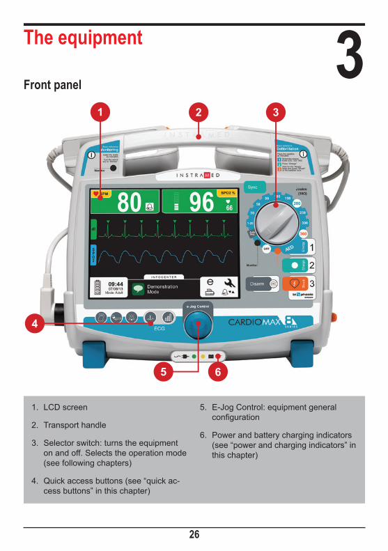
The equipment 3Front panel
26
1. LCD screen
2. Transport handle
3. Selector switch: turns the equipment on and off. Selects the operation mode (see following chapters)
4. Quick access buttons (see “quick ac-cess buttons” in this chapter)
5. E-Jog Control: equipment general configuration
6. Power and battery charging indicators (see “power and charging indicators” in this chapter)
1
4
5
2 3
6

User manual | The equipment
27
ScreenThe LCD screen displays graphic and numeric information used in ECG and SpO2, defibrillation and others. For more information about the configurations and screen information, see the “Screen and operation” section.
e-Jog ControlThe e-Jog Control is used to access all of the CardioMax's functions, such as set alarms, define information displayed on the screen, alter parameters, etc.
ROTATE: rotating allows the user to select or change information and navigate all menus. It operates similarly to a computer mouse.
PRESS: works similarly to the enter button on a computer, confirming the selection.
Selector switch
Monitor
Ene
rgy
OFF
Seq.Auto
Pacemaker
Scale from 1 to 360 Joules: allows the user to select the desired energy charge.
Monitor mode: used to monitor ECG, SpO2, NIBP, EtCO2 and RESP parameters, as in a multiparametric monitor.
Pacemaker mode (*): enables external pacemaker.
Off: turns off the equipment.
AED Position: enables external automatic defibrillator mode.
Auto Seq Mode: enables charge auto-sequencing.
NOTE: The equipment does not defibrillate in pacemaker and monitor modes. The pacemaker will only work in pacemaker mode.
(*) Check your equipment’s configuration. This item is optional and may not be present in all commercialized equipment.

User manual | The equipment
28
Quick access buttons
Power and battery charging indications1. Power Connected: when the LED is on, it indicates that the equipment is connected to a power source or an external battery.
2. Battery Charging: when the LED is on, it indicates that the battery is charging.
Fast Lead Change: enables quick access to change ECG leads.
Fast Sensitivity Change: enables quick change of ECG sensitivity.
Print: press once to print a quick report. For continuous printing, simply press the button for 3 seconds. For further information, see the “Printing” section.
Alarm silence: press the button quickly to deactivate ALL sound
alarms for a previously programmed period of time. Press for 3 seconds to deactivate ALL sound alarms for an INDETERMINATE period. For more information, see the “Alarms and limits” section.
NIBP (when available): starts or suspends the functionality of the Non-Invasive Blood Pressure Measurement. When the NIBP (optional) parameter is not present in the device, this button has no function.
OBS: When the equipment is connected to an electric current, the LEDs will light up indicating the beginning of charging, even if the CardioMax is inoperative.
1 2

User manual | The equipment
29
Side view
1 - SpO2 connectorBCI standard oximetry connector. Adult and child oximetry sensors.
2 - USB connectorUSB connector for access to data stored by the AED mode. It can be plugged directly to a Windows PC.
3 - NIBP connectorConnector for direct use with the armband.
4 - ECG connectorConnector for ECG cables. Depending on the parameters present in the equipment, it may be available in the following settings:
• 3 or 5-wire - AAMI standard. Protected against defibrillation.
• 10-wire (optional) - allows up to 12 simultaneous leads. This connector substitutes the standard connector and is not compatible with the 3 or 5-wire cables.
5 - PrinterPrinter for thermosensitive paper. It prints electrocardiograms and events. For more information view the “Printing” chapter.
1 2 3 45
6 7 8
User manual | The equipment
30
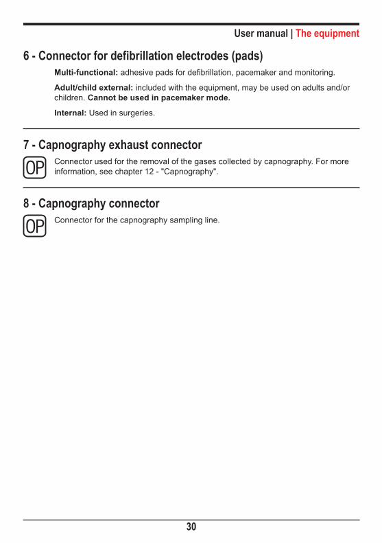
6 - Connector for defibrillation electrodes (pads)Multi-functional: adhesive pads for defibrillation, pacemaker and monitoring.
Adult/child external: included with the equipment, may be used on adults and/or children. Cannot be used in pacemaker mode.
Internal: Used in surgeries.
7 - Capnography exhaust connectorConnector used for the removal of the gases collected by capnography. For more information, see chapter 12 - "Capnography".
8 - Capnography connectorConnector for the capnography sampling line.

User manual | The equipment
31
Rear panel
1 - PadsThe pads accompanying the CardioMax must be placed on top of the equipment and must be properly connected to the adult adapter.
2 - Removable batteryThe battery can be easily replaced by simply pressing both side tabs one against the other. The battery will unlock and automatically detach itself from the equipment. NOTE: Do not remove the battery when the equipment is operating in battery mode. Connect it to an electric current first.
3 - Identification tagsThe identification tags have important information about the product, such as the model, serial number and manufacturer information. This information may be requested if technical assistance is needed. Therefore, do not remove or damage the identification tags.
4 - VentilationDo not block ventilation slots. Keep the equipment positioned in order to facilitate airflow. These slots are raised to reduce the accidental entry of liquids, as well as to prevent against spills or drips.
1
2
3
4

User manual | The equipment
32
Rear connectors
1 - 3-pin power connectorInput of 100 to 265 VAC, with central pin for grounding. 5A fuse (20mm 20AG F5A GLASS FUSE).
2 - External DC socketFor battery connection or external DC source connection in a range of 11 to 16 VDC.
3 - Grounding and potential equalizerPotential equalization and general grounding connector.
4 - RS-232 outputCable socket for updating software (reserved for authorized technical personnel).
2
1
3
4

Screen and operation 4Turning and operating
Use selector switch (1) for turning CardioMax on and off. When turning on, the operator must immediately select an operation mode (defibrillator, monitor or pacemaker).
1 - Selector switchTurn clockwise or counter-clockwise to select the operation mode. On "Off" position the equipment is turned off.
2 - Defibrillator modeEnables to set the time of the automated internal discharge of the energy stored in the device.
Monitor
Ene
rgy
OFF
Seq.Auto
Pacemaker
1
2
4
56
7
3
33

User manual | Screen and operation
34
3 - Auto Seq. modeIn this mode, it is possible to deliver shocks in a sequence of energy levels preset by the user. (See the “Defibrillator mode” chapter).
4 - Monitor modeUsed to monitor the patient's ECG, SpO2, NIBP, EtCO2 and RESP. In this position the CardioMax works as a multiparametric monitor.
ECG and SpO2 limit alarms continue operating. ECG and SpO2 messages are enabled.
5 - Turns equipment offIn this position, the CardioMax is turned off. After the device is turned off, only the circuit that charges the battery remains in operation. (This is indicated by a green LED in the base of the equipment’s front).
6 - AED modeEnables the Automated External Defibrillator (AED).
In this situation, the CardioMax is capable of assessing, through sophisticated sensors, the patient’s state, consider the clinical variables and apply, automatically, the most indicated shock therapy. At the same time, the device guides the user by verbal commands and screen indications which can be warnings, instructions or status messages.
The CardioMax’s Automated External Defibrillator will only function if the multifunctional pads (adhesive) are connected to the equipment.
7 - Pacemaker modeEnables the external pacemaker.
The external pacemaker will only work if the multifunction pads (adhesives) are connected to the equipment.

User manual | Screen and operation
35
Operating the e-Jog ControlTo access the configuration menus and equipment operation use the rotating e-Jog Control as indicated below:
STEP 1 ROTATE: Rotate the button to the desired item observing the highlighted icons on the equipment screen.
STEP 2 PRESS: Press to select the highlighted item. The menu for the chosen function will appear.
STEP 3 ROTATE: Rotate the button to the corresponding value desired in the selected item's menu.
STEP 4 PRESS: Press to confirm the new selected value.
User manual | Screen and operation
36
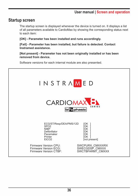
Startup screenThe startup screen is displayed whenever the device is turned on. It displays a list of all parameters available to CardioMax by showing the corresponding status next to each item:
[OK] - Parameter has been installed and runs accordingly.
[Fail] - Parameter has been installed, but failure is detected. Contact Instramed assistance.
[Not present] - Parameter has not been originally installed or has been removed from device.
Software versions for each internal module are also presented.
ECG/ST/Resp/DEA/PMS/12DSPO2NIBPDefibrillatorPacemakerPrinterEtCO2
[OK ][OK ][OK ][OK ][OK ][OK ][not present]
Firmware Version CPU:Firmware Version ECG:Firmware Version CTBF:
SWCPURX_CMXXXRXSWECGDSP_CMXXXSWCTBFARM7_CMXXX

User manual | Screen and operation
37
ECG
100BPM SPO2 %
ON DEMAND
35100mAPPM
09:4407/10/04 Shock OK
I N F O C E N T E R
100Parameters visualization screen
1. Graph area for oximetry, ECG and EtCO2 waveforms. Also used for con-figurations.
2. Time, date, battery and mode status.
3. ECG: ECG measurements and ECG alarms.
4. Pacemaker or defibrillation modes: area for the defibrillation or pacemaker modes.
5. Infocenter: Information on the equip-ment and its operation. This is how the device communicates with the user.
6. SpO2 : Oximetry measurements and oximetry alarms.
7. Access icons for event and configu-ration functions: check it on the next page.
1 2 3 4 5 6 7

User manual | Screen and operation
38
1. Events menu: views events stored in the CardioMax.
2. Configuration menu: enables the configuration of all the parameters of the equip-ment. See the “Configuration menu” in this chapter.
3. Alarms menu shortcut: configures ECG and SpO2 alarms.
4. Printer menu shortcut: prints and configures the printing parameters.
The equipment screen will display different segments and parameters according to the mode defined using the selector switch. See examples on the following pictures.
Access icons for events and configuration functions
1
4 3
2

User manual | Screen and operation
39
Monitor mode screen – variation A (ECG and SpO2 present)
09:4407/10/12
I N F O C E N T E R
BPM SPO2 %80 96 66
dII
SPO2
Mode: Adult
1 2 3 4 5 6
1. ECG: ECG measurements and ECG alarms.
2. Time, date, battery and mode status.
3. Graph area for oximetry, ECG and EtCO2 waveforms. Also used for con-figurations.
4. Infocenter: information on the equip-ment and its operation. This is how the device communicates with the user.
5. SpO2: oximetry measurements and oximetry alarms.
6. Access icons for event and configura-tion functions.

User manual | Screen and operation
40
Monitor mode Screen – variation B (ECG, SpO2, and NIBP present)
1. ECG: ECG measurements and ECG alarms.
2. NIBP: measurement values for systol-ic, diastolic and mean Non-Invasive Blood Pressure.
3. SpO2: Oximetry measurements and oximetry alarms.
4. Graph area for oximetry, ECG and
EtCO2 waveforms. Also used for con-figurations.
5. Time, date, battery and mode status.
6. Infocenter: information on the equip-ment and its operation. This is how the device communicates with the user.
7. Access icons for event and configura-tion functions.
09:4407/10/12
I N F O C E N T E R
BPM 80dII
SPO2
Mode: Adult
NIBPmmHg
( 73)104/157 98
1 2 3
4
5 76

User manual | Screen and operation
41
Monitor mode screen – variation C (all parameters present)
1. ECG: ECG measurements and ECG alarms.
2. RESP: respiration measurements and respiration alarms.
3. EtCO2: EtCO2 measurements and alarms.
4. NIBP: measurement values for systol-ic, diastolic and mean Non-Invasive Blood Pressure.
5. SpO2: oximetry measurements and oximetry alarms.
6. Graph area for oximetry, ECG and EtCO2 waveforms. Also used for con-figurations.
7. ST: ST segment values and measure-ments and ST segment alarms.
8. Time, date, battery and mode status.
9. Infocenter: information on the equip-ment and its operation. This is how the device communicates with the user.
10. Access icons for event and configura-tion functions.
17:0011/12/12
I N F O C E N T E R
BPM
80dII
SPO2
EtCO2
Mode: Adult
98ETCO2
0.2 Ins
mmHg
ST(mm)
1.0
NIBPmmHg
( 73)104/ 57
RESP
rpm162 3 4 5
6 7
8 109
1

User manual | Screen and operation
42
Pacemaker mode screen
1. ECG: ECG measurements and ECG alarms.
2. Time, date, battery and mode status.
3. Graph area for oximetry, ECG and EtCO2 waveforms. Also used for con-figurations.
4. Infocenter: information on the equip-ment and its operation. This is how the device communicates with the user.
5. Information on the pacemaker mode.
6. NIBP: measurement values for systol-ic, diastolic and mean Non-Invasive Blood Pressure.
7. SpO2: Oximetry measurements and oximetry alarms.
8. Access icons for event and configura-tion functions.
PPM mA
180 200
Mode: Adult
ON DEMAND
07/10/12
745 leads NIBP
mmHg
( 73)104/ 57 98
dII
SPO2
PM ONMode: Dem
1 2 3 4 5 7 86

User manual | Screen and operation
43
AED mode screen
1. ECG: ECG measurements and ECG alarms.
2. Time, date, battery and mode status.
3. Graph area for oximetry, ECG and EtCO2 waveforms. Also used for con-figurations.
4. Visual representation of the instruction given by the CardioMax to the user when in AED mode.
5. Transcription of the instruction given by the CardioMax to the user when in AED mode.
5 leads
07/10/12
Pads
AED
Don’t touch the patientAnalyzing the rhythm
Child padsMode: Neo
1 2 3 4 5
User manual | Screen and operation
44
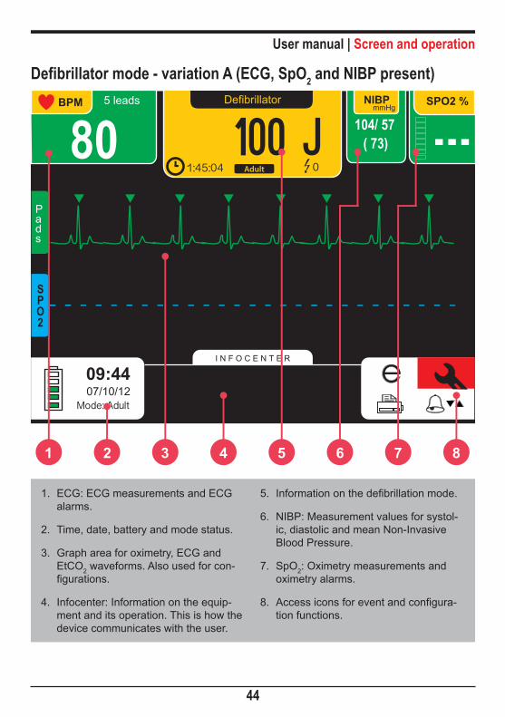
Defibrillator mode - variation A (ECG, SpO2 and NIBP present)
1. ECG: ECG measurements and ECG alarms.
2. Time, date, battery and mode status.
3. Graph area for oximetry, ECG and EtCO2 waveforms. Also used for con-figurations.
4. Infocenter: Information on the equip-ment and its operation. This is how the device communicates with the user.
5. Information on the defibrillation mode.
6. NIBP: Measurement values for systol-ic, diastolic and mean Non-Invasive Blood Pressure.
7. SpO2: Oximetry measurements and oximetry alarms.
8. Access icons for event and configura-tion functions.
Defibrillator
100 J1:45:04 Adult 0
Mode: Adult07/10/12
5 leads
80NIBP
mmHg
( 73)104/ 57
Pads
SPO2
1 2 3 4 5 7 86

User manual | Screen and operation
45
1. ECG: ECG measurements and ECG alarms.
2. EtCO2: EtCO2 measurements and alarms.
3. Time, date, battery and mode status.
4. Graph area for oximetry, ECG and EtCO2 waveforms. Also used for con-figurations.
5. Information on the defibrillation mode.
6. Infocenter: Information on the equip-ment and its operation. This is how the device communicates with the user.
7. SpO2: Oximetry measurements and oximetry alarms.
8. Access icons for event and configura-tion functions.
Defibrillator mode - variation B (ECG, SPO2 and EtCO2 present)
17:0011/12/12
I N F O C E N T E R
dII
SPO2
EtCO2
Mode: Adult
98Defibrillator
100 J2:30 Adult 0
EtCO2mmHg
rpm60 5.028
0.2
1 2 3 4 6 7 85
User manual | Screen and operation
46
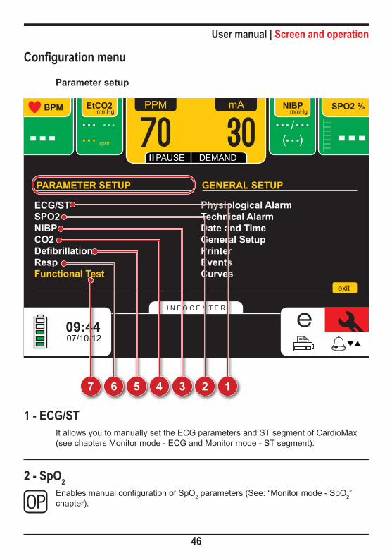
Configuration menu
Parameter setup
1 - ECG/STIt allows you to manually set the ECG parameters and ST segment of CardioMax (see chapters Monitor mode - ECG and Monitor mode - ST segment).
2 - SpO2 Enables manual configuration of SpO2 parameters (See: “Monitor mode - SpO2” chapter).
ECG/STSPO2NIBPCO2
Functional TestRespDefibrillation
Physiological AlarmTechnical Alarm
exit
Date and TimeGeneral SetupPrinter
CurvesEvents
07/10/12
EtCO2mmHg
rpm
NIBPmmHg
/( )
PPM mA
70 30PAUSE DEMAND
PARAMETER SETUP GENERAL SETUP
7 56 4 3 2 1

User manual | Screen and operation
47
3 - NIBPEnables manual configuration of NIBP parameters (See: “Monitor mode - NIBP” chapter).
4 - CO2 Enables manual configuration of CO2 parameters (See: “Monitor mode - capnography” chapter).
5 - Defibrillator modeEnables to set the time of the automated internal discharge of the energy stored in the CardioMax (See the “Defibrillator mode” chapter).
6 - RESPEnables manual configuration of RESP parameters (See the “Monitor mode – respiration” chapter).
7 - Functional testEnables to perform the CardioMax’s functional test (See the “Defibrillator mode”chapter).

User manual | Screen and operation
48
1 - Physiological AlarmIt allows you to set the alarm for each of the parameters (see section Alarms and Limits).
2 - Technical AlarmIt allows you to turn on or off different technical alarms (see section Alarms and Limits).
Configuration menu
General setup
ECG/STSPO2NIBPCO2
Functional TestRespDefibrillation
Physiological AlarmTechnical Alarm
exit
Date and TimeGeneral SetupPrinter
CurvesEvents
07/10/12
EtCO2mmHg
rpm
NIBPmmHg
/( )
PPM mA
70 30PAUSE DEMAND
PARAMETER SETUP GENERAL SETUP
7 56 4 3 2 1

User manual | Screen and operation
49
2 - Time and date
The “Time and date” menu adjusts the CardioMax’s calendar and time. You can opt for international or North-American standards of date and time. It is very important to keep time and date well adjusted because this information will appear on all printed reports.
You can adjust the time and the date using the e-Jog Control.
3 - General setup
The “General setup” menu allows you to configure four items and perform two actions.
GENERAL SETUP
BIP Volume Off 10Alarm Volume 1 10Defibrillator Volume 1 10Language Port SpanMode Neo AdultCardiac Freq. SpO2 AutoRestore original setup
[Off ][1 ][1 ][Port ][Adult ][ECG ]
exitback
TIME AND DATE SETUP
Date: 08 / 02 / 07Time: 08 : 45
exitback

User manual | Screen and operation
50
BEEP Volume - turns off or adjusts BEEP volume (BEEP is the audio indication of QRS).
Alarm Volume - alarm volume adjustment.
Defibrillator Volume - adjusts the volume of the defibrillator's audio information (charge, charge ready, shock disarmed and shock delivered).
Language - choose the language in which menus will be displayed.
Mode - enables to select Non-Invasive pressure monitoring in adult, pediatric or neona-tal patients. In neonatal mode, the armband’s initial pressure is limited to 60mmHg and in pediatric mode, the armband’s initial pressure is limited to 140mmHg.
Cardiac Frequency - enables to select the heart rate by the SpO2 sensor, ECG elec-trodes or automatic mode. In the automatic mode, priority is given to ECG elec-trodes.
Restores original setup - restores original factory settings.
4 - PrinterPrint and configure printing parameters (See the “Printing” chapter).
5 - EventsView and manage events saved in the CardioMax (See the “Events” chapter).
6 - WaveformsIn this menu, you may select which waveform will be presented on the screen (ECG, SpO2, EtCO2 or RESP waveforms) or you may view up to 3 waveforms (the EtCO2 and RESP waveforms cannot be shown at the same time). It is also possible to select the waveform scan speed. The possible speeds are 12,5mm/s, 25,0mm/s e 50,0mm/s for ECG and SpO2 and 6,25mm/s, 12,5mm/s and 25,0mm/s for EtCO2 and RESP waveforms.
OBS: if all waveforms are disabled simultaneously, the CardioMax will automatically select the “DII” lead. The EtCO2 curve will only be enabled if the module is on.
See the picture on the next page.

User manual | Screen and operation
51
.WAVEFORMS SETUP
exitback
Waveform 1 Off Pads[dII ]
Waveform 3 Off EtCO2[Off ]Waveform 2 Off SPO2[Off ]
ECG/SPO2 speed 12,5 50,0[25,0 ]12-lead ECG Off On[Off ]Initial derivation - Monitor dII Pads[dII ]Initial derivation - Def dII Pads[Pads ]

Alarms and limits 5The CardioMax has audio and visual indications of physiological and technical alarm conditions.
Physiological AlarmThere are two ways to enable the physiological alarm indications:
Asistoly - the CardioMax cannot detect valid heartbeats for over 4 seconds.
Violation of MAXIMUM or MINIMUM limits - When the Oximetry, ECG, NIBP, EtCO2 or RESP maximum or minimum alarm limits are not within the equipment's preset range.
Physiological alarm visual indications will be given in either mode, but the audio indications will only be given when the equipment is in the monitoring mode.
FEATURES:• ECG, SpO2, NIBP, EtCO2 or RESP (defibrillator mode): white, numerical value of
2 cm x 2 cm
• ECG, SpO2, NIBP, EtCO2 or RESP (monitor mode): white, numerical value of 3 cm x 1.8 cm
• Alarm indicator: blinking bell sine, numerical value of 7 mm x 7 mm
• Visual frequency: 2Hz
• Sound frequency: 440Hz at intervals of 150ms
Technical AlarmSound and visual signals indicate that the CardioMax is not able to accurately monitor the patient's status. The technical alarm indications are shown in the Infocenter area. See below a detailed list:
ECG or RESP - Loose Electrode: loose ECG electrode, poor contact between electrode and skin, or broken ECG conductor.
SpO2 - No finger on sensor: sensor connected to the device, but cannot detect the patient’s finger.
SpO2 - Searching for signal: monitor searching for valid SpO2 signal.
SpO2 - Disconnected sensor: the SpO2 sensor or extension is disconnected or badly placed.
52

User manual | Alarms and limits
53
SpO2 - Artifact: muscular spasm detected.
SpO2 - Weak signal: the CardioMax cannot identify the signal. Weak signal means the patient probably has low perfusion.
SpO2 - Lost pulse: no beats for more than 4 seconds.
Printer - Printer without paper: printer out of paper.
Printer - Printer door open: printer door is not properly closed.
NIBP - Excessive pressure: the armband’s maximum pressure has been exceeded.
NIBP - Armband problems: the armband has been wrongly placed or has a leak in its measurement circuit.
NIBP - Weak signal: pulse too weak for NIBP measurements. Check the armband’s position and tightening.
NIBP - Excessive movement: there is noise due to the patient’s moving.
NIBP - Long measurement: the pressure measurement is too long and possibly inaccurate.
EtCO2 - No Filterline: the capnography sampling line is not connected.
EtCO2 - Occlusion: there is no airflow in the EtCO2 sensor. Change the sampling line (Filterline).
EtCO2 - Starting sensor: the EtCO2 module is heating up its internal sensors (this occurs during the beginning of capnography and lasts about 15 seconds).
RESP - Apnea alarm: the alarm will emit a sound when a suspension of breathing is detected (apnea) in the specified times of 5, 10, 15, 20, 25, 30, 35 or 40 seconds (set in Menu > RESP > Apnea Alarm).
NOTE: These indications will only be enabled when the CardioMax is in monitoring mode.
Sound signals are emitted at intervals of 6 seconds whenever there is a technical alarm situation.

User manual | Alarms and limits
54
In addition to the technical alarm conditions indicated in the Infocenter, there are two other situations that may occur:
Bad contactInforms when the patient's impedance measurement does not satisfy the necessary shock delivery conditions. This information is presented in the Infocenter.
Bad Contact
Connect Multifunctional Paddles07/10/12

User manual | Alarms and limits
55
Battery charge level:
Indication Battery status* Device operating conditions
100% charged Enables approximately 3 hours of monitoring if the battery has been inserted.
80% charged Enables approximately 2 hours and 50 minutes of monitoring.
60% charged Enables approximately 1 hour and 40 minutes of monitoring.
40% charged Enables approximately 1 hour and 10 minutes of monitoring.
20% charged Enables approximately 40 minutes of monitoring.
*battery status when the AC power supply cable is not connected.

User manual | Alarms and limits
56
ECG
ON DEMAND
09:4407/10/12
I N F O C E N T E R
100BPM pad
100SPO2 %
35100mAPPM
Low battery
OK
CardioMax will turn off shortlyWarning
Connect Multifunctional Paddles
See the indication for low battery above:
1 - Five white battery bars. 2 - Dialogue box shows: “low battery”.
When you see these indications on screen, this means the equipment will turn off shortly.
1 2

User manual | Alarms and limits
57
Silence/disarm alarmWhen pressing the ALARM SILENCE button with a FAST touch (shorter than 3 seconds) ALL alarm audio indications will be silenced for a period of time predetermined by the operator.
Your visual indication is the “Alarm Silenced” icon in all parameters.
Suspend AlarmWhen pressing the ALARM SILENCE button with a LONG touch (longer than 3 seconds) ALL alarm audio indications are silenced for an INDETERMINATE period of time.
Your visual indication is the “Alarm Disarmed” icon in all parameters.
IMPORTANT: No audio alarm will emit a sound when the alarm is disarmed.
Configuration of alarm limitsWhenever the CardioMax is started, it returns to the last limits and configurations set by the user.
To alter alarm limits, the user must select the ALARM menu.
User manual | Alarms and limits
58
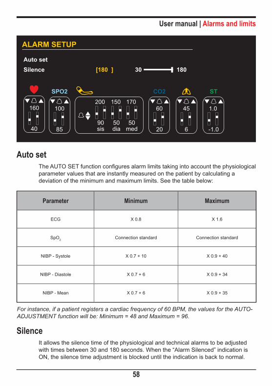
Auto setThe AUTO SET function configures alarm limits taking into account the physiological parameter values that are instantly measured on the patient by calculating a deviation of the minimum and maximum limits. See the table below:
Parameter Minimum Maximum
ECG X 0.8 X 1.6
SpO2 Connection standard Connection standard
NIBP - Systole X 0.7 + 10 X 0.9 + 40
NIBP - Diastole X 0.7 + 6 X 0.9 + 34
NIBP - Mean X 0.7 + 6 X 0.9 + 35
For instance, if a patient registers a cardiac frequency of 60 BPM, the values for the AUTO-ADJUSTMENT function will be: Minimum = 48 and Maximum = 96.
SilenceIt allows the silence time of the physiological and technical alarms to be adjusted with times between 30 and 180 seconds. When the “Alarm Silenced” indication is ON, the silence time adjustment is blocked until the indication is back to normal.
Auto setSilence 30 180[180 ]
ALARM SETUP
85
100
SPO2
20
60
CO2
6
45
-1.0
1.0
ST
90sis
200
50dia
150
50med
170
40
160
User manual | Alarms and limits
59
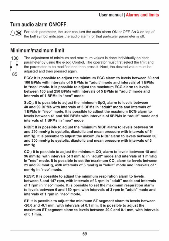
Turn audio alarm ON/OFFFor each parameter, the user can turn the audio alarm ON or OFF. An X on top of the bell symbol indicates the audio alarm for that particular parameter is off.
Minimum/maximum limitThe adjustment of minimum and maximum values is done individually on each parameter by using the e-Jog Control. The operator must first select the limit and the parameter to be modified and then press it. Next, the desired value must be adjusted and then pressed again.
ECG: It is possible to adjust the minimum ECG alarm to levels between 30 and 100 BPMs with intervals of 5 BPMs in “adult” mode and intervals of 1 BPMs in “neo” mode. It is possible to adjust the maximum ECG alarm to levels between 100 and 250 BPMs with intervals of 5 BPMs in “adult” mode and intervals of 1 BPMs in “neo” mode.
SpO2: It is possible to adjust the minimum SpO2 alarm to levels between 40 and 99 BPMs with intervals of 5 BPMs in “adult” mode and intervals of 1 BPMs in “neo” mode. It is possible to adjust the maximum ECG alarm to levels between 41 and 100 BPMs with intervals of 5BPMs in “adult” mode and intervals of 1 BPMs in “neo” mode.
NIBP: It is possible to adjust the minimum NIBP alarm to levels between 50 and 290 mmHg to systolic, diastolic and mean pressure with intervals of 5 mmHg. It is possible to adjust the maximum NIBP alarm to levels between 60 and 300 mmHg to systolic, diastolic and mean pressure with intervals of 5 mmHg.
CO2: It is possible to adjust the minimum CO2 alarm to levels between 18 and 96 mmHg, with intervals of 3 mmHg in "adult" mode and intervals of 1 mmHg in "neo" mode. It is possible to set the maximum CO2 alarm to levels between 21 and 99 mmHg, with intervals of 3 mmHg in "adult" mode and intervals of 1 mmHg in "neo" mode.
RESP: It is possible to adjust the minimum respiration alarm to levels between 3 and 147 rpm, with intervals of 3 rpm in "adult" mode and intervals of 1 rpm in "neo" mode. It is possible to set the maximum respiration alarm to levels between 6 and 150 rpm, with intervals of 3 rpm in "adult" mode and intervals of 1 rpm in "neo" mode.
ST: It is possible to adjust the minimum ST segment alarm to levels between -20.0 and -0.1 mm, with intervals of 0.1 mm. It is possible to adjust the maximum ST segment alarm to levels between 20.0 and 0.1 mm, with intervals of 0.1 mm.
85
100

User manual | Alarms and limits
60
Technical alarms settingsWhen turned on, CardioMax returns to the last limits and setting made by the user.
In order to change the active technical alarms, the user must access the "Settings> Technical alarm" menu.
Through the menu, it is possible to enable or disable the sound indications of technical alarms of ECG, SpO2, NIBP, EtCO2 and Printer. When the sound is enabled and there is a technical alarm situation in the parameter or the equipment, the equipment will send beeps at intervals of approximately 6 seconds.
TECHNICAL ALARMS SOUND
ECG Off On[Off ]SPO2 Off On[Off ]PANI Off On[Off ]EtCO2 Off On[Off ]PRINTER Off On[Off ]
Alarm TestTo carry out an alarm test, proceed as follows:
1 - Turn the equipment on without cables and with no sensors connected. A technical alarm indication (a text message in the Infocenter) must be displayed.
2 - Press the SILENCE ALARM button for 1 second and check if the “alarm disarmed” indication appears on the screen for all parameters.
Wait 60 seconds and the alarm will self-activate. The “alarm disarmed” indication will disappear from the screen and the sound alarm will return.
You can adjust the duration of the “alarm disarmed” function in the “Alarm – Silence” menu.
3 - Press the ALARM SILENCE button for 3 seconds. On the screen, you will see the permanent “alarm disarmed” indication.
The audio alarm parameters can be individually turned on and off in the alarm menu as well as in the individual parameter menus. The audio intensity of the alarm indications can be adjusted in the “Configuration - Alarm volume” menu.

Defibrillator mode 6Physics principle used
The biphasic cardiac defibrillator is an instrument that delivers energy previously stored in a capacitor to a patient. The defibrillation can be external (when the capacitor’s discharge is delivered through the patient’s thorax) or internal (applying the capacitor’s discharge directly to the heart with an open thorax and during surgical procedure).
The CardioMax uses biphasic shock technology, which is characterized by a current liberated in one direction and, after a brief period of time, reverted in the opposite direction.
During the defibrillation the myocardium is briefly depolarized by a strong positive and negative impulse of adjustable intensity (Truncated Exponential Biphasic Shock). These impulses are used to eliminate arterial, ventricular fibrillation, and ventricular disturbances.
WarningsThe CardioMax has a patient impedance meter that delivers shocks in 25 to 300 ohms impedances.
If a cable or conductor is suspected of being ruptured, avoid using the equipment due to possible risk to the operator.
Ensure that the defibrillation electrodes of the CardioMax are at an appropriate distance from other electrodes so that the power applied does not flow through these electrodes.
Disconnect all equipment devoid of protection against the discharge of defibrillators.
Ensure that the patient does not come into contact with any metallic parts.
61

User manual | Defibrillator mode
62
Use criteriaIn defibrillation mode, the CardioMax must only be used if the following circumstances, as a whole, are presented:
1 - Unconscious victim 2 - No breathing 3 - No pulse
Other important considerations regarding the use of the CardioMax:
1 - Not recommended for children under one year old. 2 - Pacemakers may affect the device’s efficiency. 3 - Medicines in adhesive form must be removed before starting defibrillation. 4 - Hypothermic patients may not respond well to defibrillation. 5 - Once the removal of the patient is started, the defibrillation must be interrupted.
Qualified usersShall be considered qualified users those who have a degree in Medicine.

User manual | Defibrillator mode
63
External pads use1 - Check if the pads are connected to the CardioMax. If they are not, connect the defibrillation cable to the pads socket located on the equipment’s side (as show in the image below).
2 - Take both pads from their base pulling them up and out.
3 - Apply the conductive material to the pads' electrodes.
4 - Place pads as shown in the image below:
AB
A - Sternum
B - Apex

User manual | Defibrillator mode
64
The electrodes must be placed in a position which will maximize the current that passes through the myocardium. The standard position is:
a) Electrode identified as “STERNUM” on the right second intercostal space, mid-clavicular line.
b) Electrode identified as “APEX” positioned on the left sixth intercostal space, midaxillary line.
ENSURE that the electrodes are away from each other. DO NOT apply paste or gel to the thorax between the pads or the current may follow a superficial route along the thorax wall and not reach the heart.
5 - Check contact with the patient
The STERNUM pad has a patient contact indicator.
The indicator goes from BAD contact (red flashing LED) to GOOD contact (at least one LED on).
Make sure to adjust the pressure and the pads' placement to optimize contact with the patient, so that AT LEAST ONE GREEN LED remains on.
GOOD BAD

User manual | Defibrillator mode
65
About shock deliveryAligning the pressure of the pads and the conductive material applied to the electrodes, different patient impedances are obtained.
The table below indicates the conditions in which the CardioMax offers or inhibits the delivery of energy.
Patient's impedance Shock Message on screen after
“Charge” key pressedValues indicated on bargraph
Short circuit Shock inhibited Bad contact All LEDs blinking
< 25 ohm Shock inhibited Bad contact All LEDs blinking
>25 ohm e < 300 ohm
Shock delivered and the waveform is adjusted according to the patient's impedance
No message LEDs lit up indicating contact level
> 300 ohm Shock inhibited Bad contact Only the red LED is blinking
Short - open Shock inhibited Bad contact Only the red LED is blinking
When all LEDs blink simultaneously the pads have a short circuit, and shock delivery will not be permitted.
When only the RED LED is blinking, shock delivery will not be allowed.

User manual | Defibrillator mode
66
Child pads use
1 - Fasten the lock in the front of the adult external pads.
2 - Pull the pads base forward to remove them.
3 - This exposes the smaller electrode for children.
1
2
3
The CardioMax will automatically identify that it is operating in pediatric mode. Energy is limited to 50 Joules in the pediatric mode.
Adult Child

User manual | Defibrillator mode
67
Using multifunction padsThe use of the multifunction pads (disposable) requires that the operator uses the adapter provided (extension cable) in order to connect them to the standard socket of the external pads, as described below:
1 - Connect the AED/pacemaker extension cable to the equipment.
2 - Connect the adhesive multifunction pads to the extension cable.
3 - Remove the multifunction pads’ protective film and apply them to the patient, using the same positions recommended for the external pads (Sternum and Apex)
ATTENTION: The pads are disposable and for single-use, cannot be reused under any circumstances.

User manual | Defibrillator mode
68
ATTENTION: After opening the wrapping, the pads should be used within 24 hours.
ATTENTION: In case of use for long periods, the pads should be replaced every 24 hours.
Defibrillation
Follow the steps 1-2-3:Step 1 - Select energy
Rotate the selection switch until you reach the energy desired. Energy options go from 1 to 360 Joules. In most cases, 200 Joules is recommended for adult use.
The CardioMax limits the energy to the internal pads to 50 Joules.
Step 2 - Charge
Monitor
Ene
rgy
OFF
Seq.Auto
Pacemaker
Press the “Charge” button (green) in the front panel or use the charge button in the external pads (orange).
While the CardioMax is charging, a sound will be emitted and the measurement of the charged energy will appear on the display.
The energy selected can be increased or decreased at any time just by rotating the selector switch to the new charge.
To cancel the shock press “Disarm”.
When the charge is complete, the device sends a sound signal and displays “Charge Ready” on the screen.

User manual | Defibrillator mode
69
Step 3 - Shock
After the “Charge Ready” warning, press the "Shock" 3 button (orange) in the front panel or use the two buttons (orange) in the external paddles.
It is only possible to defibrillate using the pad buttons with the adult/child external pads.
CAUTION: Make sure nobody is touching the patient! Tell passersby to stand clear of the patient!
The number of shocks and length of operation are indicated on the screen.
Synchronism - Synchronized discharge - Cardioversion
Remember: The function “Synchronized Shock” is disabled after the shock is delivered.
Monitor the patient with 3 or 5-leads ECG cables or with the defibrillation electrodes.
Press the “Sync” button in the front panel. Ensure that the synchronization marker is red and lined up with the 'R” wave and the “SYNC” indication is displayed next to the selected energy value.
Follow steps 1-2-3 for defibrillation.
IMPORTANT: Keep key 3 (shock) or the two shock pads’ buttons pressed until the next “R” wave is identified. The CardioMax will deliver the shock when the next “R” wave is identified.
IMPORTANT: If the CardioMax does not identify a valid QRS it will not deliver the shock!

User manual | Defibrillator mode
70
Disarm key
Disarm the stored charge. Charge may be disarmed at any time, whether the charge is ready or not.
Defibrillation display
1 - SynchronismIndicates if sync is on or off. When it is turned on, the symbol blinks indicating the function is activated.
2 - Elapsed timeIndicates how long the equipment has been used for. The marker returns to zero if the equipment is turned off.
3 - Defibrillation electrode typeShows which defibrillation electrode is connected to the equipment: ADULT (adult external pads), CHILD (child external pads), INTERNAL (internal pads) or ADHESIVE.
Defibrillator
Sync
1 2 3 4 5

User manual | Defibrillator mode
71
4 - Number of shocksShows number of shocks delivered. The counter is set to zero when the equipment is turned off.
5 - Selected and charged energyThe energy SELECTED by the user is shown in this display area in BLACK numbers.
During the equipment's charging cycle, the value of the energy that has already been stored is displayed in RED. When the charge is complete the numbers are displayed in RED and blink, indicating the equipment is ready and the shock can be delivered.

User manual | Defibrillator mode
72
Charge Auto-Sequencing mode (Auto Seq)
There are three sequential energy levels, being that, from the third shock on all subsequent shocks will use the same discharge value of the latter. The preset sequence will be interrupted in the following conditions:
• Equipment shutdown.
• Auto Seq mode exit.
• Reconfiguration of the Auto-Sequencing mode energy levels (available after the delivery of the third shock).
In case child or internal pads are used, the equipment will automatically limit the charge to 50 Joules.
Auto Sequencing
50 J100 J200 J
50:45 Adult 0
The energy to be charged is indicated in red.
Auto Sequencing
50 J100 J200 J
50:45 Adult 1
After shock delivery, the energy is updated with the next energy level.
Monitor
Ene
rgy
OFF
Seq.Auto
Pacemaker
In the Auto Seq mode, the shock energy levels will follow the order previously set by the user in: "Defibrillation > Auto Sequencing Charge” (See “Defibrillation setup” below.)

User manual | Defibrillator mode
73
Defibrillation setup
CHARGE AUTO-SEQUENCING
First ShockSecond ShockThird Shock
[50 ][100 ][200 ]
101010
360360360
DEFIBRILLATION SETUP
Internal discharge timeSudden Death Prev. OffOff On
back exit
1 2 3 4
1 - Internal discharge timeDetermines how long the equipment keeps the charge ready before discharging it internally.
2 - Sudden Death Prevention (SDP) Turn on or off the Sudden Death Prevention mode. When on adhesive pads or electrodes monitoring, the equipment sets off the alarm and shows “Shock Indicated” if ventricular fibrillation/ventricular tachycardia (VF/VT) is identified.
3 - Charge Auto-SequencingSets energy levels for the Auto Seq mode. The user can select energy levels of 10 to 360 Joules for the first, second and third shocks. Preset values are 150J for the first shock and 200 J for the next shocks.
In case child or internal pads are used, the equipment will automatically limit the charge to 50 Joules. When there is use of internal or child pads followed by the use of adult pads, the last configured values for adult pads will be recovered.
OP

User manual | Defibrillator mode
74
The charge and shock delivery processes are operated manually. After every delivery, the energy levels are updated.
4 - Back/Exit“BACK” to configuration menu or “EXIT” to go to the monitoring screen.
Functional testWARNING: The functional test must be executed daily in order to guarantee that the equipment is in working order and ready to use.
Put the Paddles on the supportSelect 100JPress CHARGEPress SHOCK
FUNCTIONAL TEST
exitback
X
Step 1Place pads on their base located on top of the equipment.
Step 2Select 100J of energy.
Step 3Press the “charge” key and wait until the equipment sends the charge ready signal.
Step 4Press the “shock” key.

User manual | Defibrillator mode
75
Result screens for functional tests
Remember: If CardioMax fails the functional test, contact technical support IMMEDIATELY.
NOTE: printouts of test results will only be available in the CardioMax units equipped with a thermal printer.
NOTE: the CardioMax indicates failure in the functional test when there is a failure in one of the 4 steps of the functional test or when the power delivered has an energy exceeding that allowed by health standards.
Put pads on the baseSelect 100JPress CHARGEPress SHOCK
Passed test!
FUNCTIONAL TEST
printOK
Functional testPassed test!
exitback
Put pads on the baseSelecit 100JPress CHARGEPress SHOCK
Failed test!
FUNCTIONAL TEST
printOK
Functional testFailed test!Contact technical support!
exitback
Equipment passed functional test
Equipment failed functional test

AED modeAutomatic External Defibrillator 7Introduction
Given the complexity of clinical variables involved, for many years only doctors and experienced paramedics could use defibrillators to reverse a cardiac arrest.
Nowadays, however, with the evolution of artificial intelligence (AI), the CardioMax, using its Neural Network Technology, is capable of assessing, via sophisticated sensors, the patient’s state, consider the clinical variables and deliver automatically the most indicated shock therapy.
This allows any individual with adequate training, to perform assistance to a victim in fibrillation process, facilitating and multiplying lifesaving possibilities
Characteristics• Artificial Intelligence: accurate diagnosis of the patient’s conditions, indicating
shock delivery or not.
• Safety safeguards: avoids accidental use, in cases in which shock treatment is not indicated or in healthy people.
• Voice orientation and screen indications.
• Internal recording of events.
• PC connection via USB.
• Connection software, data download and management via PC.
• Biphasic Shock.
• Automatic self-test.
• Use in hospital or extra-hospital environments including rescue emergency units.
76

User manual | AED mode
77
Physics principle usedThe biphasic cardiac defibrillator is an instrument that delivers energy previously stored in a capacitor to a patient. The defibrillation can be external (when the capacitor’s discharge is delivered through the patient’s thorax) or internal (applying the capacitor’s discharge directly to the heart with an open thorax and during surgical procedure).
The CardioMax uses biphasic shock technology, which is characterized by a current liberated in one direction and, after a brief period of time, reverted in the opposite direction.
During the defibrillation the myocardium is briefly depolarized by a strong positive and negative impulse of adjustable intensity (Truncated Exponential Biphasic Shock). These impulses are used to eliminate arterial, ventricular fibrillation, and ventricular disturbances.
WarningsThe CardioMax has a patient impedance meter that delivers shocks in 25 to 300 ohms impedances.
If a cable or conductor is suspected of being ruptured, avoid using the equipment due to possible risk to the operator.
Ensure that the defibrillation electrodes of the CardioMax are at an appropriate distance from other electrodes so that the power applied does not flow through these electrodes.
Disconnect all equipment devoid of protection against the discharge of defibrillators.
Ensure that the patient does not come into contact with any metallic parts.

User manual | AED mode
78
Use criteriaIn defibrillation mode, the CardioMax must only be used if the following circumstances, as a whole, are presented:
1 - Unconscious victim 2 - No breathing 3 - No pulse
Other important considerations regarding the use of the CardioMax:
1 - Not recommended for children under one year old 2 - Pacemakers may affect the device’s efficiency 3 - Medicines in adhesive form must be removed before starting defibrillation 4 - Hypothermic patients may not respond well to defibrillation 5 - Once the removal of the patient is started, the defibrillation must be interrupted
Qualified usersShall be considered qualified users those who have a degree in Medicine.

User manual | AED mode
79
OperationBefore starting the operation, call the emergency service.
Step 1 - Connect disposable pads to the CardioMax
If the disposable pads have not been connected to the CardioMax yet, attach the connector to the plug on the right side of the equipment.
After disposing of used pads, always leave a replacement pair already connected to the equipment, avoiding having to replace them at the mo-ment of the emergency.
ATTENTION: this device has electronic safeguards and will not operate in inadvisable situations.
Check patient’s condition. Only use the equipment if the patient is not breathing.
NOTE: When using child pads, the shock will be set in 50 Joules.

User manual | AED mode
80
Step 2 – Apply pads to patient
Remove pads from their wrapping and peel off the film protecting the adhesive.
Place pads on the patient according to the picture above, keeping adhesive area in contact with the skin.
This position allows the electric current to circulate from one pad to the other, thus reaching the whole thoracic cage.
ATTENTION: the area in contact with the pads must be dry.
he presence of too much hair in the contact area may affect scanning. In this case, shave hair.
ATTENTION: the pads must be applied directly over the skin. DO NOT place pads over clothes.
Sternum
Apex

User manual | AED mode
81
Step 3 - Select AED
Rotate the selector switch to the AED position.
The CardioMax will automatically enter cardiac rhythm analysis mode and will start giving vocal instructions clearly and pausedly, so that the user can perfectly understand them.
ATTENTION: the patient must be on a steady surface. Any movement during the process of clinical analysis will result in mistaken scans.
ATTENTION: the pads are disposable and can be used in only one patient at a time. Remember to always keep extra ones with the equipment. For replacements, please contact Instramed.
Monitor
Ene
rgy
OFF
Seq.Auto
Pacemaker
Analyzing cardiac rhythm...

User manual | AED mode
82
Step 4 - Deliver shock
If the need for shock is detected, the shock symbol will blink and the device will ask the user to press the shock button again.
Press “SHOCK” button again.
The shock will be delivered
ATTENTION: the user must not touch the patient or conductive surfaces in contact with him/her during shock delivery, under risk of suffering a powerful electric discharge.
NOTE: The energy delivered is pre-adjusted. The user cannot alter this protocol. For adult electrodes: 1st shock is 150 Joules and the following are 200 Joules; for child electrodes, all shocks are 50 Joules.
If clinical scans show that defibrillation is not recommended, the CardioMax will announce: “TREATMENT NOT RECOMMENDED”.
Check if there was no movement of the patient during the analysis. If so, restart the process. If not, remove pads and start the CPR (cardiopulmonary resuscitation) procedure. Details on the next section.
Press shock button!

User manual | AED mode
83
Step 5 - Start CPR
30X
2X
After the shock, start the CPR procedure.
CPR (cardiopulmonary resuscitation) is a technique which consists in mechanical stimulation of the lungs and heart. Through simple actions, it aims to maintain the oxygenation of the brain, avoiding irreversible damage.
Applying CPR
1) Lay the victim on his back on a hard flat surface.
2) Run your fingers from the center of the victim’s thorax, descending until finding a bone that comes to a tip in the middle of the chest (Sternum), right above the stomach.
3) Keep two fingers right below this point.
4) Place the palm of your other hand above the two fingers that indicate the base of the Sternum bone. This is the correct spot for the massage.
CONTINUES>
2 min

User manual | AED mode
84
5) Put one palm on top of the other, keeping your fingers curled up without touching the thorax. In small children, however, use only your fingers. Apply force according to the victim’s size.
6) Keep your arms stretched. Put pressure on the victim’s thorax, compressing the chest and then releasing it. Follow the BEEPS emitted by the CardioMax, which mark the rhythm of the compressions. Every 30 compressions, apply 2 mouth-to-mouth ventilations.
7) Performing mouth-to-mouth breathing:
• Place one hand on the back of the victim’s neck and lift it; place your other hand on the victim’s forehead and force the head back, in order to let the air through.
• Close the victim’s nostrils with the fingers which are on the forehead.
• Take a deep breath, and place your open mouth on the victim’s mouth (if it is a child, also cover the nose with your mouth).
• Force air inside the victim’s lungs, until the thorax inflates, as in normal breathing.
• Allow the person to release the air by removing your mouth.
8) At every interval to perform mouth-to-mouth breathing, check if the patient’s pulse is back.
The massage and ventilation cycle must be done for two minutes. If the patient’s pulse does not return, restart shock procedure with the CardioMax.
After the third complete CPR and shock cycle, chances of the patient’s resuscitation are very slim.
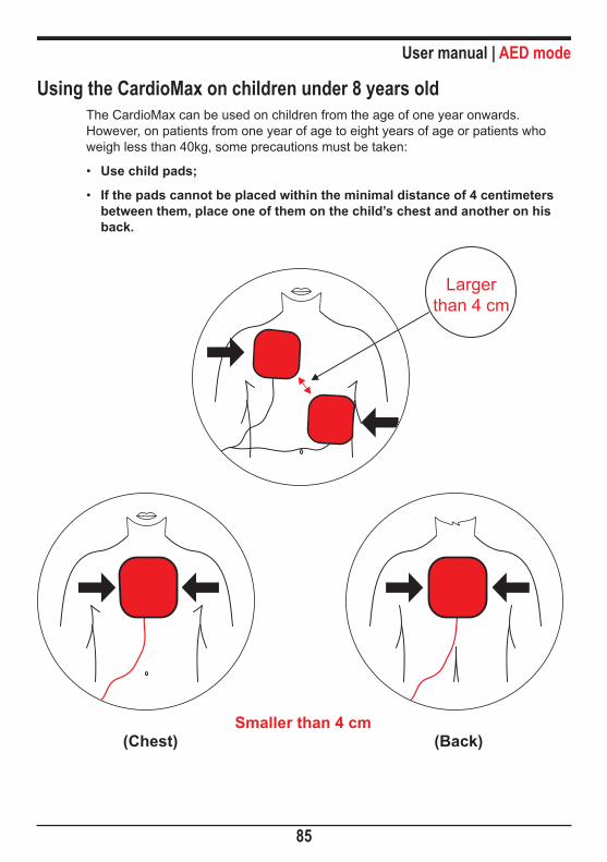
User manual | AED mode
85
Using the CardioMax on children under 8 years oldThe CardioMax can be used on children from the age of one year onwards. However, on patients from one year of age to eight years of age or patients who weigh less than 40kg, some precautions must be taken:
• Use child pads;
• If the pads cannot be placed within the minimal distance of 4 centimeters between them, place one of them on the child’s chest and another on his back.
(Chest) (Back)Smaller than 4 cm
Larger than 4 cm
Pacemaker mode 8Physics principle used
The external pacemaker applies a squared waveform of variable frequency and intensity to the heart in order to stimulate heartbeats. In a normal heart, the heart beats as follows: the sinoatrial node, located in the right atrium, stimulates the heart's contraction. It is controlled by the parasympathetic system that by freeing acetylcholine, performs a depressor effect while a sympathetic innervation, when stimulated, produces noradrenaline, which accelerates the rhythm. This potential is then propagated through the atrial myocardium and then reaches the second most important system center, the atrium-ventricular node, also located in the right atrium, which transmits the potential to the ventricles through the atrium-ventricular and its branches.
The pacemaker uses electrical stimulation to reproduce or regulate the heart's rhythm.
Its function is to supply pulses in order to stimulate the heart. These pulses have two characteristics that must be adjusted: The number of pulses per minute (PPM) and the strength of the current (mA). The pacemaker works in two modes: fixed or on demand (synchronous).
WarningsThe CardioMax has a patient impedance meter that delivers shocks in 25 to 300 ohms impedances.
If a cable or conductor is suspected of being ruptured, avoid using the equipment due to possible risk to the operator.
86

User manual | Pacemaker mode
87
Fixed modeIn this mode, the pacemaker does not consider the patient's heart frequency and applies the PPM number defined by the user.
Demand mode (synchronous)In this mode the CardioMax assesses the patient's heart rate, applying the PPM number selected in the panel only when the heart rate is lower than the PPM value indicated. It must be within at least 5 BPM (the security margin) for the pacemaker to work.
In this mode, the pacemaker uses the ECG signal captured by the electrodes (patient cable), synchronizing the pulses in order to prevent the heart’s vulnerable phase.
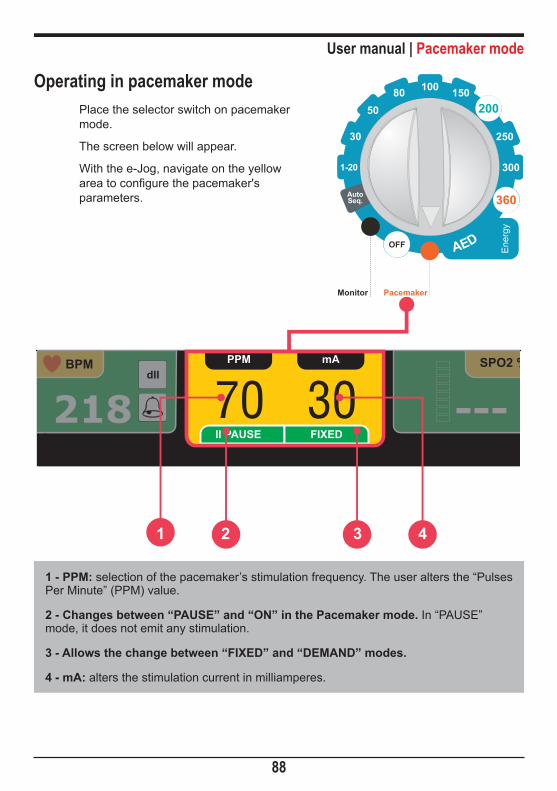
User manual | Pacemaker mode
88
Monitor
Ene
rgy
OFF
Seq.Auto
Pacemaker
Operating in pacemaker modePlace the selector switch on pacemaker mode.
The screen below will appear.
With the e-Jog, navigate on the yellow area to configure the pacemaker's parameters.
1 - PPM: selection of the pacemaker’s stimulation frequency. The user alters the “Pulses Per Minute” (PPM) value.
2 - Changes between “PAUSE” and “ON” in the Pacemaker mode. In “PAUSE” mode, it does not emit any stimulation.
3 - Allows the change between “FIXED” and “DEMAND” modes.
4 - mA: alters the stimulation current in milliamperes.
218BPM
dII
---SPO2 %
70PPM mA
30II PAUSE FIXED
1 2 3 4

User manual | Pacemaker mode
89
Starting stimulation1 - If it not yet connected, connect the adhesive pads cable to the CardioMax.
2 - Check if the multifunction adhesive pads package is intact and within the expiration date.
3 - Insert the adhesive pads connector into the equipment's extension cable.
4 - Put the adhesive pads on the patient according to package instructions.
5 - In case of demand mode stimulation, apply ECG monitoring electrodes.
Fixed stimulation1 - Rotate the dial to the pacemaker mode.
The pacemaker starts in PAUSE, without stimulation pulses.
The mode must be changed to FIXED.
2 - Select the leads for ECG viewing.
3 - With the e-Jog, adjust the initial current and frequency (PPM) values (see the previous page). The current value must be as low as possible.
4 - Go to “ON” with the e-Jog, in order to start stimulation. A message in the “Infocenter” will inform the pacemaker is active.
5 - Check if the pacemaker's pulse meter appears on the screen.
6 - Increase the stimulation current until the heart rate is captured. This is indicated by the presence of the QRS complex (Q, R and S waveforms) right after the pacemaker marker.

User manual | Pacemaker mode
90
Under demand stimulation1 - Rotate the selector switch to the pacemaker mode. The pacemaker starts in PAUSE, without stimulation pulses.
2 - Select the leads for viewing the ECG. Check if the “R” wave indicators mark every “R” wave present on the screen. If not change the derivation.
3 - Adjust the initial current values and frequency (PPM) with the e-jog. The current value must be as low as possible.
4 - With the e-Jog, go to “ON” to start stimulation. A message in the “Infocenter” will warn that the pacemaker is active.
5 - Check if the pacemaker's pulse meter appears on the screen.
6 - Increase the stimulation current until cardiac capture occurs. The capturing is indicated by the presence of a QRS straight after the pacemaker marker.
NOTES:
There may be spontaneous beatings not related to the application of stim-ulation. If the patient's heart frequency is above the pulse's frequency, the stimulation pulses will not be applied and the stimulation markers will not appear.
Stimulation will not start if there is a problem with the multifunction (ad-hesive) paddles or contact with the patient.
The stimulated pulses will be applied in the asynchronous mode if there is a connection problem with the ECG monitoring electrodes or if the Car-dioMax does not identify a valid QRS.
DefibrillationIf defibrillation is necessary, turn the switch to defibrillation mode. The CardioMax automatically inhibits the pacemaker's stimulation pulse.

Monitor mode - ECG 9Physics principle used
ECG is the measurement of electrical potential generated by the depolarization and re-polarization of heart cells, generating the bioelectrical impulse responsible for the heart's contraction. Heart impulses are detectable on the body surface by applying electrodes. Each electrode's potential is amplified and processed by the heart monitor, displayed on the screen and then used to calculate the heart's frequency (BPM).
The heart cycle period is the elapsed time from any point in the ECG cycle to the corresponding point in the next cycle. For example, the interval “R-R” is the time between two successive “R” waves. Using this measurement, it is possible to determine the beats per minute (BPM).
WarningsUse only original Instramed cables and conductors. Other ECG cables may impede defibrillation or not work correctly.
If you suspect a cable or conductor is ruptured, avoid its use due to possible risk to operator.
If the patient has a pacemaker, do not rely solely on the equipment alarms. Keep the patient under observation.
The cardiac frequency measurement can be affected in the presence of a transcutaneous pacemaker.
The ECG electrodes are disposable and single-use and cannot be reused under any circumstances.
91

User manual | Monitor mode - ECG
92
Monitoring ECG1 - Connect the ECG cable into the ECG socket in the equipment's side panel.
2 - Select the electrodes to be used on the patient. Use only one kind or brand of electrode. The electrodes must follow AAMI standards for electrode performance.
3 - Prepare the application area according to the manufacturer instructions.
4 - Apply the electrodes according to the images below, following the color pattern on the table on the following page.
5 - Connect the patient's ECG cable to the electrodes.
RRA
LLA
FLL
RRA
LLA
FLL
NRL
CV1 V2
V3V4 V5 V6
3-wire cable 5-wire cable
(3 leads) (7-12 leads)
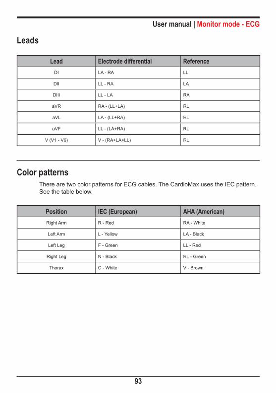
User manual | Monitor mode - ECG
93
Leads
Lead Electrode differential ReferenceDI LA - RA LL
DII LL - RA LA
DIII LL - LA RA
aVR RA - (LL+LA) RL
aVL LA - (LL+RA) RL
aVF LL - (LA+RA) RL
V (V1 - V6) V - (RA+LA+LL) RL
Color patternsThere are two color patterns for ECG cables. The CardioMax uses the IEC pattern. See the table below.
Position IEC (European) AHA (American)Right Arm R - Red RA - White
Left Arm L - Yellow LA - Black
Left Leg F - Green LL - Red
Right Leg N - Black RL - Green
Thorax C - White V - Brown
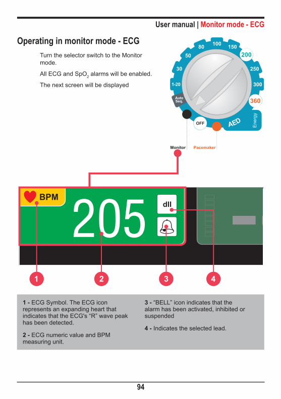
User manual | Monitor mode - ECG
94
Monitor
Ene
rgy
OFF
Seq.Auto
Pacemaker
Operating in monitor mode - ECGTurn the selector switch to the Monitor mode.
All ECG and SpO2 alarms will be enabled.
The next screen will be displayed
205BPM
dII --1 2 3 4
1 - ECG Symbol. The ECG icon represents an expanding heart that indicates that the ECG's “R” wave peak has been detected.
2 - ECG numeric value and BPM measuring unit.
3 - “BELL” icon indicates that the alarm has been activated, inhibited or suspended
4 - Indicates the selected lead.

User manual | Monitor mode - ECG
95
ECG Setup
WAVEFORM
ECG Response Lenta Fast[Normal ]
ECG Cable 3-wire 10-wire[5-wire ]
Detect Pacemaker Off On[Off ]
ST Segment Off On[Off ]
Sensitivity 5 40[20 ]
Frequency bandwith Diag Monitor[Monitor ]
Mains supply filter Desl Lig[On ]
-1.0
1.0
40
160
ECG ST
ECG SETUP
back exit
1
5
4
7
2
6
3
8
9
1 - ECG responseSelect the ECG numeric update response. You can select from “SLOW, “NORMAL” and “FAST” responses.
NORMAL: used for most patients, this mode uses 16 beats to define the average.
FAST: used when the operator needs faster responses. It is affected by the patient's movements, using 8 beats to define the average.
SLOW: less affected by the patient's movements. However, you must pay attention to the slow response of the heart rate variation. This mode uses 32 beats to define the average.
2 - ECG cableIt allows selecting the ECG monitoring by cable with 3 lead, 5-lead or 10-lead.
Using the 3-wire ECG cable in the SDP (Sudden Death Prevention) makes it functional only in the DII lead.
User manual | Monitor mode - ECG
96
3 - Detect pacemakerEnables to turn the pacemaker detection mode on or off. When on, the equipment indicates on the screen the pacemaker’s pulse moment. Detect pacemaker mode must only be used on patients with pacemaker.
4 - ST segmentIt allows turning on or off the ST segment monitoring. When turned on, the device indicates on the screen the measured value for the ST segment. See "Monitor mode - ST segment" chapter.
5 - SensitivitySelect the ECG amplification gain. You can select from 5, 10, 15, 20, 30 or 40 mm/mV.
6 - Frequency bandwidth selectionFilter selection for power interference. “Diag” or “Monitor”.
7 - Mains supply filterEnables to turn filter on or off to reduce mains supply interference with the ECG signal.
8 - Alarm“BELL” icon which indicates sound alarm “ON” or “OFF”. Configuration of “MINIMUM” and “MAXIMUM” alarm limits.
9 - Back/Exit“Back” to Configuration menu and “Exit” to monitoring screen.

Monitor mode - ST segment 10Physical principle used
The ST segment monitoring is used to diagnose occurrences of acute myocardial infarction.
The acute myocardial infarction is a necrosis process of a part of the cardiac muscle that occurs by the interruption of blood flow in the coronary arteries. Early diagnosis is key factor in reducing mortality and possible consequences for the patient.
One of the most accurate ways to this diagnosis is the identification of abnormalities in ST elevation, identifiable through electrocardiographic evaluation (ECG).
When an ST elevation greater than 2 mm is detected, the patient may be suffering from acute phase of a myocardial infarction.
When an ST segment depression greater than 2 mm is detected, the patient may be suffering a myocardial ischemia (undernutrition of a certain part of myocardial).
Unevenness of up to ± 2 mm is common and normal in healthy patients.
97

User manual | Monitor mode - ST segment
98
Characterization of ST elevationThe waves recorded in the ECG are identified by points ranging from P to T, as shown in figure 1.
The ST segment begins at the point that the QRS set ends, showing upward curve in a normal situation.
The indication of possible acute myocardial infarction is an obvious decrease in the ST segment, represented by the reduction or reversal of concavity in this region of the curve (other figures).
ST
T
ST elevation
ST
T
ST
T
ST depression ST depression
PQ
R
S
T
Time (1s)
Miliv
olts
0
1
2
-1
-2
Normal ST segment(Fig. 1)

User manual | Monitor mode - ST segment
99
ST levels detectionCardioMax has internal algorithms for measuring ST levels. It will be measured up to 3 segments ST, in accordance with the derivation present on the screen.
The values of the segments will be displayed at the end of each curve, as shown below.
09:4407/10/12
I N F O C E N T E R
BPM SPO2 %80 96 66
dI
dII
dIII
Mode: Adult
ST(mm)
1.0
2.0
0.5
ST segment configurationThe display of the ST segment can be turned on or off in the "ECG Settings" (see section "ECG Settings" on page 95).
ATTENTION: the ST segment values cannot be displayed when the deriva-tion "paddles" is selected or when ECG monitoring mode with 12-lead (optional) is enabled.

NIPB monitoring 11Physics principle used
CardioMax uses oscillometric mode to calculate Non-Invasive blood pressure. A armband is used to convey arterial pressure changes caused by blood flow. The armband is insuflated to a pressure higher than systolic pressure in order to occlude blood flow in extremities. Gradually, armband pressure is reduced generating little pulses or oscillations.
Mean pressure is the lowest pressure in the armband, in which detected oscillation peaks have higher amplitude. Systolic pressure occurs when oscillation increases quickly and diastolic pressure occurs when oscillation decreases in the same intensity. As a characteristic of oscillometric mode, mean pressure is the most precise one.
WarningsIf you suspect a cable or conductor is ruptured, avoid using the equipment due to possible risk to the operator.
The armband must not be applied on the same limb or extremity where the SpO2 sensor is. When inflating the armband, SpO2 monitoring may be affected.
Do not place armband on limb or extremity which is being used for intravenous infusion, or in any area where circulation is compromised.
The CardioMax shows the results of the last NIBP measurement until a new measurement is obtained. If the patient’s conditions change between measurements, the monitor will not detect it.
Patient’s excessive movements may cause imprecise measurements.
During NIBP monitoring, avoid compression or restriction of the pressure tubes.
The NIBP connection is protected against defibrillation discharges. It is not necessary to remove the armband from the patient or disconnect it in case of defibrillation.
In case the equipment is accidentally wet, dry it with a clean cloth.
100

User manual | NIPB monitoring
101
Monitoring Non-Invasive Pressure1 - Connect the extremity of the extension hose to the equipment’s front panel.
2 - Measure the limb in which the armband will be applied to and select an adequate type. See the chart below.
3 - Place the armband according to the “Placing the armband” item.
4 - Connect the armband to the extension hose.
5 - Select one of the measurement modes: manual, automatic or stat.
ARMBAND SELECTION:Armband Limb circumference (arm/leg)
Child 10 to 19 cm
Pediatric 18 to 26 cm
Adult 25 to 35 cm
Extra Large 33 to 47 cm
PLACING THE ARMBAND:1 - Select the measurement place. Choose a place with good blood circulation, without skin problems and in which armband use does not harm the patient. Because of convenience and because of the fact that standard values are based on this location, give preference to the upper arm.
2 - Check the armband’s appropriate size for the chosen area according to the previous chart. 3 - Make sure the limb is supported to guarantee that the armband is at the heart’s level. Due to the hydrostatic effect, placement above or below the heart’s level may cause incorrect measurements.
4 - Ensure the ARTERY Mark is above the brachial artery.
User manual | NIPB monitoring
102
Measurement modes1 - Manual: Instantaneous measurement of systolic, diastolic and mean pressure.
To activate the manual mode, press NIBP MANUAL MEASUREMENT in the front panel or in the NIBP Menu Setup, select the Manual Measurement item.
When pressing the NIBP MANUAL MEASUREMENT button while the mon-itor is exerting the NIBP measurement, it will immediately interrupt the measurement.
2 - Long-term automatic: Automatic measurements of systolic, diastolic and mean pressures. Measurements are automatically repeated during the time set by the operator.
To activate the automatic mode select the desired time in the Configuration Menu > NIBP. Interval between measurements can be selected to: 1, 2, 3, 4, 5, 10, 15, 30, 60, 90 minutes.
Interrupting NIBP measurements: To cancel an ongoing pressure mea-surement, press “NIBP MANUAL MEASUREMENT”, located in the equip-ment’s front panel. The CardioMax does not offer a short-term automatic measurement option.

User manual | NIPB monitoring
103
NIBP numeric indicator
120/80(100)10
mmHg
0
1
2
3
1 - Numeric values for systolic/diastolic and mean pressures.
2 - Number of measurements exerted
(used in automatic measurements).
3 - Time interval between measurements (used in automatic measurements).
NIBP setupUsing the e-Jog select the NIBP function in the setup menu to access the NIBP setup sub-menu.
Manual MeasurementNIBP On/Off Off On
Off 90Initial pressure 60 240
[Lig ] [Lig ][60 ]
NIBP SETUP
exitback
80
300
75
300
80
300
sys dia mean
5
Automatic Measurement
1 432 5 6
0
NIBP

User manual | NIPB monitoring
104
1 - Manual measurementStart a NIBP manual measurement.
2 - NIBP ON/OFFEnables or disables the CardioMax’s NIBP function.
3 - Automatic measurementStarts the NIBP automatic measurement mode. When selecting this function, a measurement is immediately exerted. Posterior measurements will be exerted in the time set by the user. Time can be selected to OFF,1, 2, 3, 4, 5, 10, 15, 30, 60, 90 minutes.
4 - Initial pressureSelect the initial pressure for the armband’s insufflation.
5 - Alarm“BELL” icon – indicates if the sound alarm is on or off. Sets the minimum and maximum alarm limits.
6 - Back/Exit“BACK” to configuration menu or “EXIT” to monitoring screen.

Monitor mode - SpO2 12Physics principle used
The CardioMax measures oxygen saturation on arterial blood by the passage of two light wavelengths through the body tissue, a red one and an infrared one which are detected by a photo-sensor.
The oximeter processes these signals, separating invariable parameters (thickness of tissue, skin color, light intensity and venous blood) from the variable parameters (arterial volume and SpO2) in order to identify pulse frequency and calculate oxygen saturation. Calculation of oxygen saturation is precise due to the fact that blood saturated with oxygen absorbs less red light than blood with less oxygen.
The CardioMax measures functional saturation, not detecting significant quantities of dysfunctional hemoglobins, such as carboxyhemoglobin or methemoglobin.
WarningsUse only original SpO2 sensors manufactured by Instramed. Other sensors may cause inadequate performance.
If you suspect a cable or conductor is ruptured, avoid using the equipment due to possible risk to the operator.
Before using the sensor carefully read instructions which accompany it.
Do not wet the SpO2 sensor.
When handling the SpO2 cable, be careful not to strangle the patient.
The SpO2 sensor should be repositioned every 4 hours, alternating its location.
Any condition that may restrict blood circulation, such as the armband of the arterial pressure device or extremes of systemic vascular resistance may affect the precision of the pulse frequency and SpO2 readings.
105

User manual | Monitor mode - SpO2
106
Factors which affect the SpO2 measurement’s precision• Incorrect use of the sensor.
• Anemia.
• Use of vasoactive drugs.
• Patient in shock or cardiac arrest.
• Significant number of dysfunctional hemoglobins.
• Intravascular contrasts such as indocyanine green and methylene blue.
• Arterial occlusion next to the sensor.
Sensor selectionChoose an appropriate sensor in the chart below. Check the instructions which accompany the sensor for application instructions.
Patient Place Description
Adult/ Pediatric Finger (hand)
Finger or toe (hand or foot)
12556: Sensor, adult. Ref: 3044
12475: Sensor, “Y” universal. Ref: 3043
Child Finger or foot 12475: Sensor, “Y” universal. Ref: 3043

User manual | Monitor mode - SpO2
107
Monitor
Ene
rgy
OFF
Seq.Auto
Pacemaker
Operating in monitor mode - SpO2
Select the selector switch to Monitor mode.
All ECG and SpO2 alarms will be enabled.
The following screen will be displayed.
1 - “BELL” icon displaying “alarm”, “inhibited alarm” or “suspended alarm” indications.
2 - Digital scale indicating pulse amplitude.
3 - SpO2 numeric value.
4 - Patient’s pulse frequency value, obtained by the oximetry sensor.
4321
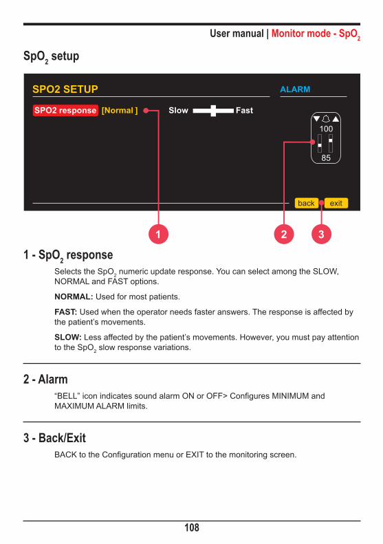
User manual | Monitor mode - SpO2
108
SPO2 response Slow Fast[Normal ]
SPO2 SETUP
exitback
85
100
ALARM
SpO2 setup
1 - SpO2 responseSelects the SpO2 numeric update response. You can select among the SLOW, NORMAL and FAST options.
NORMAL: Used for most patients.
FAST: Used when the operator needs faster answers. The response is affected by the patient’s movements.
SLOW: Less affected by the patient’s movements. However, you must pay attention to the SpO2 slow response variations.
2 - Alarm“BELL” icon indicates sound alarm ON or OFF> Configures MINIMUM and MAXIMUM ALARM limits.
3 - Back/ExitBACK to the Configuration menu or EXIT to the monitoring screen.
321
Monitor mode - Capnography 13Physics principle used
Capnography is a Non-Invasive measurement usually presented by a graph of expiratory CO2 plotted against time.
The Microstream method is used in intubated or non-intubated patients. A sample of the gas exhaled by the patient is collected by cannulas and sent to the Microstream chamber and sensor inside the CardioMax. CO2 measurement is based on the characteristics of laser absorption by CO2 molecules.
Capnography consists of measuring and registering the carbon dioxide released at the end of expiration (EtCO2). The capnograph is an EtCO2 analyzer which displays its concentration or partial pressure both digitally and in graph record. The main information given by the capnograph are the exhaled CO2 partial pressure at the end of expiration, respiratory frequency and the capnogram.
WarningsNever cut or bend the EtCO2 sample line. The use of folded or cut sample line can damage the equipment and prevent proper operation of the module.
The EtCO2 sample line is disposable and single-use and cannot be reused under any circumstances.
109

User manual | Monitor mode - Capnography
110
Capnography monitoringTo start the EtCO2 measurement, navigate through the “Configuration Menu – CO2” – and set the “CO2 – On/Off” item to ON.
Right after the start, the EtCO2 module performs a procedure called “au-to-zero”, which is necessary for the proper functioning of the equipment. During this procedure, no measurements are exerted.
The CardioMax can monitor EtCO2 in intubated or non-intubated patients. To do so, you just need to change the following accessories.
Connect the following accessories:
• Intubated patient: sampling line and “T” connector.
• Non-intubated patient: sampling line and nasal cannula.
Nonintubated patient Intubated patient
Sampling line Sampling line
"T" connector

User manual | Monitor mode - Capnography
111
Sampling lineThe sampling line collects a sample of the gas released by the patient.
In intubated patients the sampling line is directly connected into the circuit via the “T” connector.
In non-intubated patients the sampling line is connected to the cannula and positioned on the patient.
“T” connectorConnects the sampling line into the main ventilation circuit.
The sampling lines are disposable and non-washable.
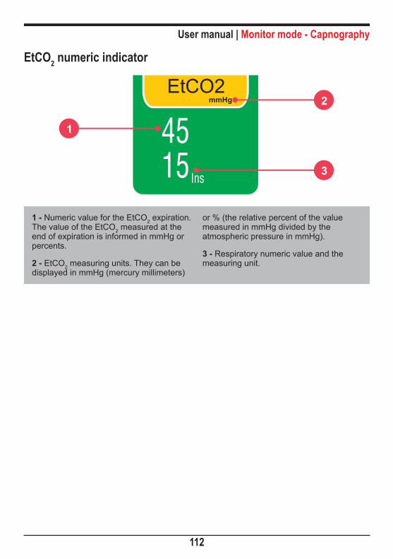
User manual | Monitor mode - Capnography
112
EtCO2 numeric indicator
1
2
3
1 - Numeric value for the EtCO2 expiration. The value of the EtCO2 measured at the end of expiration is informed in mmHg or percents.
2 - EtCO2 measuring units. They can be displayed in mmHg (mercury millimeters)
or % (the relative percent of the value measured in mmHg divided by the atmospheric pressure in mmHg).
3 - Respiratory numeric value and the measuring unit.

User manual | Monitor mode - Capnography
113
EtCO2 setupUsing the e-Jog select the EtCO2 function in the setup menu to access the EtCO2 setup sub-menu.
1 - CO2 ON/OFFTurns the CO2 module on or off. When on, the sampling pump is also operating. The numeric values, graphs and CO2 alarms will be activated.
2 - UnitsSelects the measuring units of the CO2 values. They can be displayed in mmHg (mercury millimeters) or % (the relative percent of the value measured in mmHg divided by the atmospheric pressure in mmHg).
3 - ScaleAlters the CO2 gain graph on the screen.
OnmmHg100
CO2 On/OffUnits
CALIBRATION
[On ] Off [mmH ] %
Scale [ 40 ] 40
Calibration
EtCO2 SETUP
21
60
RESP EtCO2
exitback
1 2 3 4 5 6

User manual | Monitor mode - Capnography
114
4 - CalibrationThe equipment is calibrated using a known gas sample, thus configuring its measuring curve.
IMPORTANT: Calibration must be performed when the equipment shows a message requiring this procedure during initialization. Calibration must be performed by QUALIFIED TECHNICAL PERSONNEL.
5 - EtCO2 alarm“BELL” icon – indicates if the sound alarm is on or off. Sets the minimum and maximum alarm limits.
Is it possible to adjust the EtCO2 minimum alarm to levels between 18 and 96 mmHg, with a 3 mmHg interval when in “Adult” mode and a 1 mmHg interval when in “Neo” mode. It is possible to adjust the EtCO2 maximum alarm to levels between 21 and 99 mmHg, with a 3 mmHg interval when in “Adult” mode and a 1 mmHg interval when in “Neo” mode.
6 - Back/Exit“BACK” to Configuration menu or “EXIT” to monitoring screen.
Monitor mode - Respiration 14Physics principle used
The respiration waveform is generated by the measurement of the patient’s bioimpedance. By means of a high frequency signal, which is applied to two electrodes (RA and LA), the thoracic impedance variation caused by the effort of breathing is detected and displayed on the monitor, in graph and numeric forms.
WarningsIf you suspect a cable or conductor is ruptured, avoid using them.
The respiratory rhythm must be used to detect apnea.
Patient’s excessive movements may cause imprecise measurements.
115

User manual | Monitor mode - Respiration
116
Respiration monitoringThe breathing signal is obtained by ECG electrodes. For more information o connections see the “ECG monitoring” chapter.
In order to improve breathing performance, you can change the position of the ECG electrodes, opting for alternative places. You must reposition RA and LA in a way so that they are applied bellow the nipples, as shown in the picture below:
RRA
LLA
FLL
WARNING: When repositioning the electrodes, the ECG waveform and amplitude may change.
WARNING: Only the respiration numeric value is obtained by the CO2 module. The waveform is not.
Capnography: The monitor can also show the respiratory frequency cal-culated by the Capnography module. In order to this, set the function in the Configuration Menu (Menu>RESP>RESP Freq).

User manual | Monitor mode - Respiration
117
Respiration numeric indicator
RESP
rpm
ap161
2
3
4
1 - Respiration symbol.
2 - Apnea alarm – displayed when breathing suspension is detected.
3 - Respiration numeric value.
4 - Measuring unit (respirations per minute).
Yellow indicators show that the respiratory frequency is originated via ECG cable, blue indicators show that the respiratory frequency is originated via capnography.
If the EtCO2 and respiration are on in the defibrillator and pacemaker modes, the respiration numeric indicator will be shown in the EtCO2 window, with the same color indications (check picture below).
EtCO2mmHg
rpm
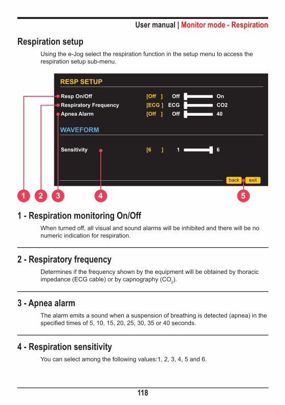
User manual | Monitor mode - Respiration
118
Respiration setupUsing the e-Jog select the respiration function in the setup menu to access the respiration setup sub-menu.
WAVEFORM
Sensitivity [6 ] 1 6
RESP SETUP
Resp On/OffRespiratory FrequencyApnea Alarm
[Off ][ECG ][Off ]
OffECG
Off
OnCO240
back exit
1 2 3 4 5
1 - Respiration monitoring On/OffWhen turned off, all visual and sound alarms will be inhibited and there will be no numeric indication for respiration.
2 - Respiratory frequencyDetermines if the frequency shown by the equipment will be obtained by thoracic impedance (ECG cable) or by capnography (CO2).
3 - Apnea alarmThe alarm emits a sound when a suspension of breathing is detected (apnea) in the specified times of 5, 10, 15, 20, 25, 30, 35 or 40 seconds.
4 - Respiration sensitivityYou can select among the following values:1, 2, 3, 4, 5 and 6.

User manual | Monitor mode - Respiration
119
5 - Back/Exit“BACK” to Configuration menu or “EXIT” to monitoring screen.

Event and data storage 15Data storage
The CardioMax creates an event list for each patient observing the following criteria:
Automatically - a new patient is identified every time the equipment is turned on.
Manually - via the events setup menu.
The quantity of events the equipment can store will vary according to how long each patient has used the equipment and the type of therapy used. The CardioMax has a 2 Mb memory.
The last two hours of continuous ECG will be stored in the equipment’s memory.
ATTENTION: Whenever the internal memory capacity reaches its limits, events prior to 100 will be replaced with new information.
Events storedThe CardioMax stores date, time, heart frequency and saturation of the following events:
• Pads change
• Charge values
• Number of shocks
• Turn equipment on/off
• Loose electrode/bad contact in the pads
• Failure in module initialization
• Functional test stimulation
• Synchronism
• Operation mode (monitor,
pacemaker, monitoring)
• Stimulation - pacemaker on/off
• “Silent alarm” key activation
• Shock failure
• Internal discharge
• Physiological alarm activation
• “Event setting” key activation
• Printing
• Low battery/equipment turning off
• Pacemaker stimulus change
120

User manual | Event and data storage
121
100 100PLAY DEMANDA
35100
09:44I N F O C E N T E R
Time EventsPatient3
NewPatient
ClearMemory
0%
PrintList
sairvoltar
100DEMANDA
35
T E R
View ExitEventsEndotracheal AccessIntravenous AccessAdrenaline/EpinephrineLidocaineAtrophineMorphineNitroglycerinAspirin
Choque Aplicado
T E R
Applied
New patientChange pads - AdultCardioMax offCardioMax onChange pads - AdultCardioMax offCardioMax onChange pads - AdultEndotracheal access
back exit
Viewing and managing events
Event setting works on defibrillator, monitor and pacemaker mode and allows you to manually mark the following items:
Events, Endotracheal Access, Intravenous Access, Adrenaline/Epinephrine, Lidocaine, Atrophine, Morphine, Nitroglycerin and Aspirin.
To view, manage and print stored events use the e-Jog control to select the “e” icon in the main screen’s configuration menu.
Also use the e-jog to navigate through events and available settings.
Visualizing events is also possible by accessing the Events option in the configuration menu.

User manual | Event and data storage
122
12:32 CardioMax desligado12:35 CardioMax ligado12:35 Troca de pas - Adulto13:02 CardioMax desligado13:02 CardioMax ligado13:02 Troca de pas - Adulto13:02 Acesso Endotraquial
100 100PLAY DEMANDA
35100
09:44I N F O C E N T E R
Time EventsPatient3
NewPatient
ClearMemory
0%
PrintList
sairvoltar
New patientChange pads - AdultCardioMax offCardioMax onChange pads - AdultCardioMax offCardioMax onChange pads - AdultEndotracheal access
back exit
1 - PatientIndicates the number of the active patient and enables changing patients.
2 - Print listPrints a list of events associated with a specific patient, including related events and the moment when each event occurred.
3 - Delete memory/used memoryDeletes every event from the memory. It Indicates the percentage of memory that has already been used (2Mb limit).
NOTE: When 100% of the memory has been used, the contents of the event memory must be deleted.
1 2 3 4 5 6

User manual | Event and data storage
123
4 - New patientCreates a new patient and initiates a new table of events.
5 - Events listPresents the selected patient's events.
6 - Printing iconWhen present next to an event, this icon indicates that printing the ECG waveform associated with that event is available. 15 seconds of an ECG curve are stored for each event which displays this icon.
To print the curve, the table must be selected by browsing the table of events using the e-Jog Control. After selecting an event, quickly press the printing button in the front panel to print it.
15 seconds of the ECG wave related to the selected event will be printed, 5 seconds before the event and 10 seconds after the event.
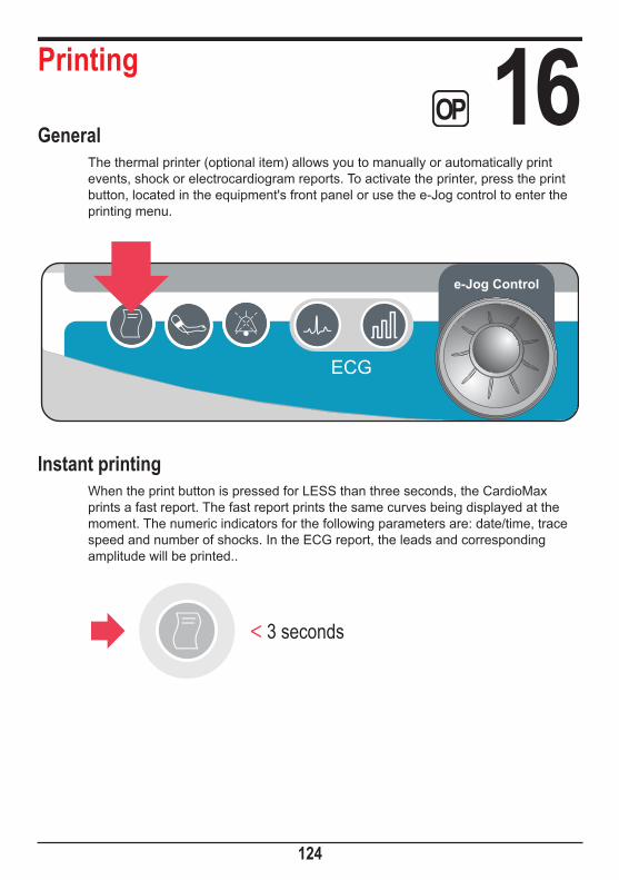
Printing 16General
The thermal printer (optional item) allows you to manually or automatically print events, shock or electrocardiogram reports. To activate the printer, press the print button, located in the equipment's front panel or use the e-Jog control to enter the printing menu.
e-Jog Control
Instant printingWhen the print button is pressed for LESS than three seconds, the CardioMax prints a fast report. The fast report prints the same curves being displayed at the moment. The numeric indicators for the following parameters are: date/time, trace speed and number of shocks. In the ECG report, the leads and corresponding amplitude will be printed..
3 seconds
124

User manual | Printing
125
ECG: SPO2:[171] bpm [100] %
10/25/04 18:19:51 25 mm/s 30 mm/mVdII
Shock: Time:3 05:17
5 cm
of p
aper
5 cm
(2 in
) pap
er
Quick printing (ECG)
Continuous printingWhen the print button is pressed for MORE than three seconds, the CardioMax prints a continuous report for an indeterminate period of time or until printing is interrupted. The data in the continuous report is identical to the data in the quick printing. See the instructions below for more information on use.
Stop printingTo interrupt continuous printing or instant printing, press the print key again.
3 seconds
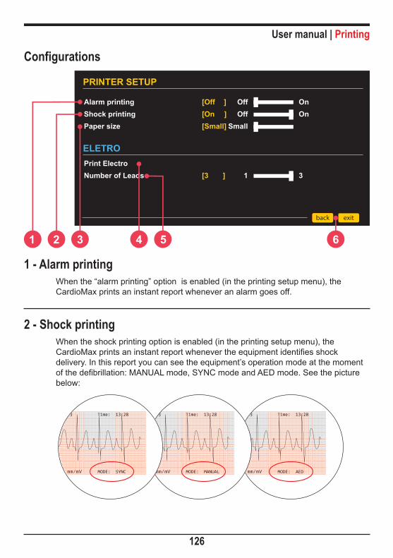
User manual | Printing
126
Configurations
ELETROPrint ElectroNumber of Leads
[3 ] 1 3
PRINTER SETUP
Alarm printingShock printingPaper size
[Off ][On ][Small]
OffOff
Small
OnOn
back exit
1 2 3 4 65
1 - Alarm printingWhen the “alarm printing” option is enabled (in the printing setup menu), the CardioMax prints an instant report whenever an alarm goes off.
2 - Shock printingWhen the shock printing option is enabled (in the printing setup menu), the CardioMax prints an instant report whenever the equipment identifies shock delivery. In this report you can see the equipment’s operation mode at the moment of the defibrillation: MANUAL mode, SYNC mode and AED mode. See the picture below:

User manual | Printing
127
3 - Paper sizeInforms the equipment of the paper size be used for printing:
Large = 30 m length
Medium = 23 m length
Small = 14 cm length
4 - Electrocardiograph functionTo print a 7-lead electrocardiogram use the print Electro function, in the printing setup menu. When this function is selected, the equipment begins monitoring and printing the leads, starting by the DI lead. At the end of printing, it returns to its normal monitoring mode.
5 - Number of leadsSelect the number of leads to be printed simultaneously, in the electrocardiograph function. The DI, DII, DIII, AVR, AVL, AVF and C leads will be printed sequentially, individually or in groups, in this same sequence, according to the defined value. The C lead is always printed individually. In case the ECG cable used is a 3-wire one, it is not possible to print more than one lead simultaneously.
6 - Back/Exit“Back” to configuration menu or “EXIT” to go to the monitoring screen.

PC connection 17Introduction
The CardioMax can be connected to a PC, allowing the user access to new functions as:
• View, save in external media or print list of the last 100 events.
• View, save in external media and print ECG activity of the last two hours.
• Change the operational configurations of the CardioMax (only for authorized technical personnel).
• Check and update firmware version of the equipment (only for authorized technical personnel).
RequirementsConnecting the CardioMax to a PC requires installation of the Soft DEA application in the computer to which a connection will be made. This software is in the CD which accompanies the equipment.
To install Soft DEA, observe the following requirements:
• Windows XP, Windows Vista or Windows 7 operating system
• CPU of 300 MHz or faster
• 02 GB free hard disk space
• Minimum 512 MB RAM (1 GB recommended)
• CD or DVD ROM reader unit
For physical connection to the PC:
• An available USB port
128

User manual | PC connection
129
Soft DEA Installation• Insert the program CD in the CD/DVD ROM drive.
• If the autorun does not start automatically, find the “softdeasetup.exe” file in the CD and double-click it.
• Follow the installation instructions which will show up on the screen.
Connecting the CardioMax to a PC• Connect the equipment only after installing Soft DEA.
• After the installation connect the device through the USB cable given.
• The location of the device drivers to be installed will be required. They can be found in this folder: C:\Program Files\Instramed\Soft DEA\DRIVERS.
• Start the Soft DEA application.
• On the language selection screen, choose among Spanish, English or Portuguese. You only have to select a language the first time you start the software.
• Start the list of events and ECG waveform display following the steps in the next section..

User manual | PC connection
130
Startup Screen
1
1 - Graphic display buttonClick this button to display the ECG waveforms and event list stored on the device. The displayed interval corresponds to the user-defined time frame (see item 7 on page 128 of this manual).
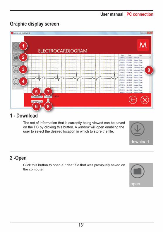
User manual | PC connection
131
Graphic display screen
1
2
3
4
5 7
6 8
9
1 - DownloadThe set of information that is currently being viewed can be saved on the PC by clicking this button. A window will open enabling the user to select the desired location in which to store the file.
2 -OpenClick this button to open a ".dea" file that was previously saved on the computer.
download
open

User manual | PC connection
132
3 - PrintClick this button to print the set of information that is currently displayed on the screen. Use the printer driver dialog box to set printing options.
4 - PDFClick this button to generate a file showing the set of information that is currently displayed on the screen in pdf format. The user must select the desired directory in which to save the file.
5 - Amplitude selectionAllows the user to vary the ECG amplitude from 0.5 mV to 3.0 mV.
6 - Time frameAllows the ECG to be viewed in time frames from 1 second to 60 seconds.
7 - Time frame scrollAllows the ECG to be viewed throughout its time scale.
8 - Amplitude scrollAllows the ECG to be viewed throughout its amplitude scale.
9 - Event viewer windowAfter downloading the information contained in the CardioMax memory, the list of events stored by the device will be displayed in this area in chronological order. Double click on an event to view it on the main screen.
Definition of events displayed in AED mode:
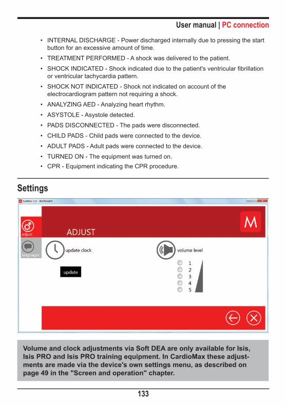
User manual | PC connection
133
• INTERNAL DISCHARGE - Power discharged internally due to pressing the start button for an excessive amount of time.
• TREATMENT PERFORMED - A shock was delivered to the patient.
• SHOCK INDICATED - Shock indicated due to the patient's ventricular fibrillation or ventricular tachycardia pattern.
• SHOCK NOT INDICATED - Shock not indicated on account of the electrocardiogram pattern not requiring a shock.
• ANALYZING AED - Analyzing heart rhythm.
• ASYSTOLE - Asystole detected.
• PADS DISCONNECTED - The pads were disconnected.
• CHILD PADS - Child pads were connected to the device.
• ADULT PADS - Adult pads were connected to the device.
• TURNED ON - The equipment was turned on.• CPR - Equipment indicating the CPR procedure.
Settings
Volume and clock adjustments via Soft DEA are only available for Isis, Isis PRO and Isis PRO training equipment. In CardioMax these adjust-ments are made via the device's own settings menu, as described on page 49 in the "Screen and operation" chapter.
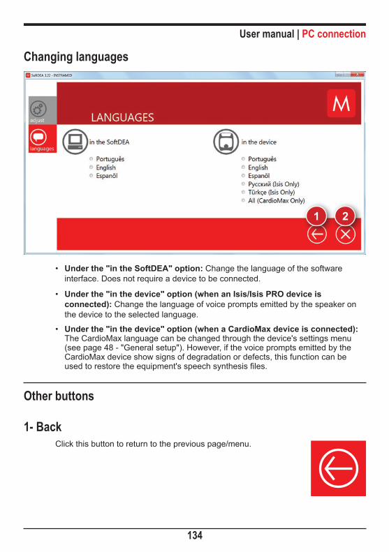
User manual | PC connection
134
Changing languages
•
1 2
Under the "in the SoftDEA" option: Change the language of the software interface. Does not require a device to be connected.
• Under the "in the device" option (when an Isis/Isis PRO device is connected): Change the language of voice prompts emitted by the speaker on the device to the selected language.
• Under the "in the device" option (when a CardioMax device is connected): The CardioMax language can be changed through the device's settings menu (see page 48 - "General setup"). However, if the voice prompts emitted by the CardioMax device show signs of degradation or defects, this function can be used to restore the equipment's speech synthesis files.
Other buttons
1- BackClick this button to return to the previous page/menu.

User manual | PC connection
135
2- ExitClick this button to close Soft DEA 3.

Care and maintenance 18Preventive maintenance
Instramed recommends that the CardioMax be examined by a qualified technician ev-ery 12 months. We recommend that you contact the manufacturer for more information about qualified and trained personnel in your area to perform preventive maintenance.
It is recommended that periodic inspections be performed on the equipment's power supply charger, cables and connectors in order to determine possible isolation or internal conductor ruptures.
Functional tests must be performed at the beginning of every work shift.
Corrective maintenanceIf the equipment needs repair, this can only be done by Instramed or its authorized representative, otherwise this Warranty certificate may no longer be valid.
No internal parts are to be fixed by the user.
Cleaning and disinfectionInstramed recommends cleaning and disinfecting the equipment and its accessories every three months, or shorter periods whenever excessive dirt or contamination is noticed.
Equipment:• Remove the equipment from the electric current before cleaning it.
• Wipe the external part of the equipment with a cloth dampened with water and neutral soap or isopropyl alcohol.
Armlet:• Clean with water and dry cloth.
• When cleaning in a washing machine *, remove the rubber cuff and place in the machine just the armlet. Use detergent and a maximum temperature of 54°C.
ATTENTION: Never let water in the pipe during washing clamp.
* Armlets that do not have a detachable rubber cuff should not be cleaned in the washing machine.
136

User manual | Care and maintenance
137
Accessories:• Use a cloth dampened with isopropyl alcohol.
• Rub the surface for about 10 minutes.
SterilizationInstramed recommends that the set of internal pads and their adult electrodes be sterilized using the “cold sterilization” method, making the right use of chemical ETO (ethylene oxide) ensuring quality control of sterilization process and handling by specialized professionals. However, the connector of the internal pad set (which is connected to the equipment) should not be immersed with the entire length of this accessory.
ATTENTION: NEVER sterilize any parts of the equipment or its accesso-ries using “dry heat sterilization”, such as when using an autoclave. This will damage the mechanical structure and compromise functioning.
Removable batteryEven when disconnected (stand-by), the CardioMax executes internal routines checking the status of the equipment. In spite of this procedure entailing a low power consumption, the battery charge may be consumed. Therefore, whenever the device has not been connected to an electric current for more than 20 days, it is advisable to execute a full battery charge. If this procedure is not performed, there is a risk of draining the battery and consequently being unable to use the Cardio-Max in its portable configuration (not connected to the electric current). To recharge the battery, connect the monitor to To charge the battery, connect the monitor to an AC power source (110 or 220V outlet) or a DC power source.
There are no restrictions or limitations for using the CardioMax while its battery is being recharged by an AC source or DC External source.
Every battery has a determined lifetime, which is the possible quantity of full charge and discharge cycles, without loss of performance (see battery specifications in chapter 8). If the equipment presents a loss in battery performance, please request a new set to Instramed's technical assistance. To request pieces and services, please contact Instramed at +55 (51) 3073-8200
The battery’s lifetime is at least 500 cycles (full charges and discharges).

User manual | Care and maintenance
138
Removable battery replacementThe battery will automatically detach itself from the equipment as shown in the picture below.
1 - Press the side tabs to unlock the removable battery.
2 - Manually remove the battery from the equipment.
3 - Correctly position the new battery, as shown in the picture below.
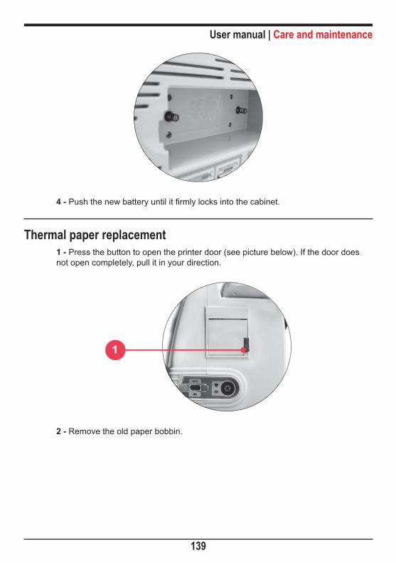
User manual | Care and maintenance
139
4 - Push the new battery until it firmly locks into the cabinet.
Thermal paper replacement1 - Press the button to open the printer door (see picture below). If the door does not open completely, pull it in your direction.
1
2 - Remove the old paper bobbin.

User manual | Care and maintenance
140
3 - Place the new bobbin between side clasps. The bobbin must be positioned as shown in the picture above, with the thermal-sensitive side (measurements in milli-meters) facing up.
4 - Unroll about 10 cm of paper.
5 - Align paper with the printer door.
6 - Close the printer door. The printer is ready for use.
Returning componentsIf CardioMax must be returned for repair, call Instramed for shipping instructions. To facilitate assistance be prepared to provide the equipment's series number.
If possible, use the original equipment’s packaging. If this is not possible, use an equivalent box that provides adequate protection for the monitor.
RepairsPlease contact Instramed at +55 (51) 30738200 or at [email protected] or [email protected] in case of repairs or further doubts.
In order to help us assist you, please be ready to inform the equipment’s serial num-ber.
In case you send us the equipment for repairs, try to use its original packaging. If it is not possible, use proper packaging and protect the monitor well.

User manual | Care and maintenance
141
Precautions, Restrictions and WarningsThe CardioMax is a device built according to NBR and IEC standards and therefore offers total safety for patient and operator. However, all safety precautions de-scribed below must be followed.
The monitor's operation can be affected by the presence of electromagnetic power sources, such as electrosurgical equipment and computer tomography (CT).
1 - ECG1 - To guarantee protection against the effects of a defibrillation, use only the patient cable that accompanies the equipment.
2 - If the monitor is used simultaneously with an electric scalpel, position the ECG electrodes as far as possible from the RF current route, between the surgical field and the neutral card. Do not use needle type ECG electrode during surgical procedures.
2 - SpO2 1 - The device’s operation may be affected by the presence of strong sources of electromagnetic energy, such as electrosurgical equipment or computed tomog-raphy equipment (CT). Operation may also be harmed by the presence of strong lights. If it is necessary, protect the area of the sensor (using, for example, a surgi-cal towel).
2 - Any dyes injected into the blood stream, such as methylene blue, indocaine green, indigo carmine and fluorescein, may affect the SpO2 reading precision. The presence of dyshemoglobin, such as carboxyhemoglobin (in consequence of carbon monoxide poisoning) or methemoglobin (in consequence of sulfonamide’s treatment) may affect the SpO2 reading precision.
3 - Electromagnetic compatibilityWarning:Installing the CardioMax requires special precautions concerning electromag-netic compatibility according to the information contained in this manual.
Mobile and portable RF communications equipment, such as mobile phones, can affect the CardioMax’s functioning.
Maximum length of accessories cables - in compliance with electromagnetic compatibility requirements:

User manual | Care and maintenance
142
ECG cable 5 leads (code 7900-5) 2.5m
Set of external defibrillation pads (code 79001) 2.5m
SpO2 finger sensor cable (code 12556) + SpO2 finger cable extensor (code21176) 2.5m
Pacemaker cable (code 79023) 2.5mWARNING:
Using cables, transducers and accessories different from the ones specified above, except for the ones sold by Instramed as replacement pieces, may result in emission increase or immunity decrease of the equipment.
The CardioMax must not be used too close to or piled over other equipment.
When the equipment is used in a surgical procedure simultaneously with an electric scalpel, there is a risk of burnouts if a defect in the connection of the neutral electrode of the high frequency equipment matches a defect in the CardioMax's ECG socket. This type of accident will only occur when the defects occur simultaneously, as the CardioMax's ECG socket is electrically protected against risks of burnouts, being completely insulated.
Electromagnetic emissions
Directives and manufacturer declaration - electromagnetic emissions
The CardioMax is intended for use in the specific electromagnetic environment below. The customer or user of the defibrillator is advised to ensure that it is used in such an environment.
Tests Compliance Electromagnetic environment - directives
RF Emissions ABNT NBR IEC CISPR11 Group 1
The CardioMax only uses RF power for its internal functions. Nevertheless, its RF emissions are very low and are not likely to cause any interference in nearby electronic equipment.
RF Emissions ABNT NBR IEC CISPR11 Class B
The CardioMax is suited for use in any establishment. This includes residential establishments and those directly connected to the public network of distribution of low voltage electricity which supply domestic use buildings.
Harmonics emissions IEC 61000-3-2 Class A
Voltage fluctuations/\flicker emissionsIEC 61000-3-3 Complies
NOTE: It is of paramount importance that the true efficacy of the RF shielding and the true attenuation of the RF filter of the shielded location are checked to ensure that they meet or exceed the minimum values specified.

User manual | Care and maintenance
143
Directives and declaration of the manufacturer - electromagnetic emissions
The CardioMax is intended to be used in the specific electromagnetic environment below. The user or customer of the defibrillator should ensure that it is used in such an environment.
Immunity Test Test Level - ABNTNBR IEC 60601 Compliance Level Electromagnetic Environment -
Directives
Electrostatic discharge (ESD) IEC 61000-4-2
± 6 kV contact
± 8 kV air
± 6 kV contact
± 8 kV air
Floors should be made of wood, concrete or tiles. If floors are covered with synthetic material, the relative humidity should be at least 30%.
Electrical fast transient/Burst IEC61000-4-4
± 2 kV for power supply lines
± 1 kV for input/output lines
± 2 kV for power supply lines
± 1 kV for input/output lines
The quality of the power supply should be that of a typical commercial or hospital environment.
Surge IEC 61000-4-5
± 1 kV differential mode (phase - phase)
± 2 kV common mode (phase - ground)
± 1 kV differential mode (phase - phase)
± 2 kV common mode (phase - ground)
The quality of the power supply should be that of a typical commercial or hospital environment.
Voltage dips, short interruptions, and voltage variations on power supply input lines IEC 61000-4-11
< 5% UT( > 95% dip in UT) for 0.5 cycle40% UT(60% dip in UT) for 5 cycles70% UT(30% dip in UT) for 25 cycles< 5% UT(> 95% dip in UT) for cycle of 5 seconds
< 5% UT( > 95% dip in UT) for 0.5 cycle40% UT(60% dip in UT) for 5 cycles70% UT(30% dip in UT) for 25 cycles< 5% UT(> 95% dip in UT) for cycle of 5 seconds
The quality of the power supply should be that of a typical commercial or hospital environment. If the user of the defibrillator requires continued operation during power interruption, it is advisable that the CardioMax is supplied by an uninterrupted power source or a battery.
Power frequency (50/60 Hz) magnetic field IEC 61000-4-8
3 A/m 3 A/m
Power frequency magnetic fields should be at characteristic levels of a typical commercial or hospital environment.
NOTE UT is the ac mains voltage prior to application of the test level.
Electromagnetic immunity - General
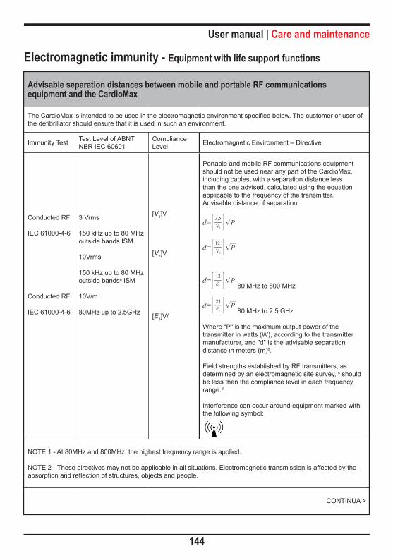
User manual | Care and maintenance
144
Electromagnetic immunity - Equipment with life support functions
Advisable separation distances between mobile and portable RF communications equipment and the CardioMax
The CardioMax is intended to be used in the electromagnetic environment specified below. The customer or user of the defibrillator should ensure that it is used in such an environment.
Immunity Test Test Level of ABNT NBR IEC 60601
Compliance Level Electromagnetic Environment – Directive
Conducted RF
IEC 61000-4-6
Conducted RF
IEC 61000-4-6
3 Vrms
150 kHz up to 80 MHz outside bands ISM
10Vrms
150 kHz up to 80 MHz outside bandsa ISM
10V/m
80MHz up to 2.5GHz
[V1]V
[V2]V
[E1]V/
Portable and mobile RF communications equipment should not be used near any part of the CardioMax, including cables, with a separation distance less than the one advised, calculated using the equation applicable to the frequency of the transmitter.Advisable distance of separation:
80 MHz to 800 MHz
80 MHz to 2.5 GHz
Where "P" is the maximum output power of the transmitter in watts (W), according to the transmitter manufacturer, and "d" is the advisable separation distance in meters (m)b.
Field strengths established by RF transmitters, as determined by an electromagnetic site survey, c should be less than the compliance level in each frequency range.d
Interference can occur around equipment marked withthe following symbol:
NOTE 1 - At 80MHz and 800MHz, the highest frequency range is applied.
NOTE 2 - These directives may not be applicable in all situations. Electromagnetic transmission is affected by the absorption and reflection of structures, objects and people.
CONTINUA >

User manual | Care and maintenance
145
a ISM bands (industrial, medical and scientific) between 150kHz and 80MHz are 6,765MHz to 6.795MHz; 13.553Mhz to 13.567MHz; 26.957MHz to 27.283MHz; and 40.66MHz to 40.70MHz.
b The compliance levels in the ISM frequency bands between 150kHz and 80MHz and in the frequency range between 80MHz and 2.5GHz are intended to reduce the likelihood of mobile and portable communications equipment causing interference if inadvertently brought into the patient areas. Therefore, an additional factor of 10/3 is used in calculating the advisable separation distance for transmitters in these frequency ranges.
c Field strengths established by fixed transmitters, such as base stations for radio, telephones (cell phone/wireless) mobile land radios, amateur radio, AM and FM radio broadcast and TV broadcast cannot be predicted theoretically with any accuracy. In order to evaluate the electromagnetic environment due to fixed RF transmitters, it is advisable to consider an electromagnetic site survey. If the measured field strength in the site where the CardioMax is used exceeds the level of RF compliance used above, the CardioMax should be observed to check if operation is normal. If abnormal performance is observed, additional procedures may be required, such as reorienting or repositioning the CardioMax.
d Over the frequency range 150kHz to 80MHz, the field intensity should be less than [V1]V/m.

User manual | Care and maintenance
146
Electromagnetic immunity - Equipment with life support functions
Advisable separation distances between mobile and portable RF communications equipment and the CardioMaxThe CardioMax is intended for use in an electromagnetic environment in which radiated RF disturbances are controlled. The customer or user of the defibrillator can help to prevent electromagnetic interference by maintaining a minimum distance between the mobile and portable RF communications equipment (transmitters) and the CardioMax as recommended below, according to the maximum output power of the communication equipment.
Maximum output power of the transmitter
W
Distance of separation according to the frequency of the transmitter (m)
150 kHz to 80 MHz outside ISM bands
150 kHz to 80 MHz outside ISM bands
80 MHz to 800 MHz 800 MHz to 2.5 GHz
0,01 0,35 1,2 0,12 0,230,1 1,1 3,8 0,38 0,731 3,5 12 1,2 2,310 11 38 3,8 7,3100 35 120 12 23
For transmitters with a maximum output power not listed above, the advisable separation distance "d" in meters (m) can be determined by using the equation applicable to the frequency of the transmitter, where "P is the maximum output power of the transmitter in watts (W) according to the transmitter manufacturer.
NOTE 1 - At 80MHz and 800MHz, the separation distance for the highest frequency range is applied.
NOTE 2 - The ISM (industrial, medical and scientific) frequency bands between 150kHz and 80MHz are 6.765MHz to 6.795MHz; 13.553 MHz to 13.567MHz; 26.957MHz to 27.283MHz; and 40.66MHz to 40.70MHz.
NOTE 3 - An additional factor of 10/3 is used in calculating the advisable separation distance for transmitters in the ISM frequency bands between 150kHz and 80MHz and in the frequency range 80MHz to 2.5GHz to reduce the likelihood of interference that mobile/portable communications equipment could cause if taken inadvertently to patient areas.
NOTE 4 - These directives may not be applicable in all situation. Electromagnetic transmission is affected by the absorption and reflection of structures, objects and people.

Troubleshooting 19
147
Symptom Probable cause Probable solution
The CardioMax does not turn on There is no electricity - Check connections: the CardioMax/Power Cable/Plug.
Does not select energy > 50J Adult pads identification - Check if is adult pads are connected to the equipment and if adult electrodes are properly connected.
Does not deliver shock Impedance measuring - Check the graph bar for the patient’s impedance indication.
Does not capture ECG via electrodes Lead selection - Select a lead other than the “pads” lead.
No tracing Unstable since last shutdown - Restore initial configuration.
Low battery autonomy Defective battery - Turn off battery.
No QRS audio indication BEEP volume - Turn on BEEP’s volume in the configuration menu.
No alarm sound indications Operation mode - Alarm indications are only active in the monitor mode
No SpO2 curve SpO2 curve turned off - Turn on SpO2 curve in Waveform Setup.
Pacemaker does not start Multifunction/Adhesive pads
- Check if multifunction pads are connected;- Check if there is a “bad contact” message;- Check gel in multifunction pads.
Does not print No paper in the printer - Check if there is paper in the printer;- Check if paper is positioned properly.
Printer makes noises and does not print Too much paper on roll - Change roll’s size.

Accessories 20Accessories accompanying the equipment:
BasicQuantity Description Code
01 Power cable (3 pins) 5550
01 Auxiliary cable for grounding and potential equalization 5495
01 Removable battery 79008
01 User manual 22619
DefibrillatorQuantity Description Code
01 A set of adult/child external defibrillation pads 79001
ECGQuantity Description Code
01 5-lead ECG cable 79005
NIBPQuantity Description Code
01 Adult armband 18562
01 Armband extensor 12432
SpO2
Quantity Description Code01 Oximetry sensor 12556
01 Oximetry sensor extensor 21176
148

User manual | Accessories
149
Pacemaker
Quantity Description Code01 Trunk cable 79023
01 Multifunctional pads 20637
List of optional accessories
Description CodeInternal defibrillation electrode - adult 72532
Internal defibrillation electrode - child 72524
Cable for internal electrodes - adult and child 79013
Y 3043 type oximetry sensor 12475
Y 3043 type oximetry sensor holder 13218
Cable for external DC connection 70319
EtCO2 sample line 20363
ECG electrodes (100 units set) - children 23897
ECG electrodes (100 units set) - adult 21669
Thermal printer paper 10766
EtCO2 set, including: 79032
• Tracheal sample line - adult 22686
• Tracheal sample line - children 22687
• Nasal sample line - adult 22688
Specifications and safety 21
150
General specificationsDimension with pads: 30.0 cm (L)
21.5 cm (P)28.0 cm (A)
Weight: Device - 5.15 kg (11.35 lbs)NiMH battery - 1.10 kg (2.43 lbs) Li-Ion battery - 0.60 kg (1.32 lbs) External pads - 0.85 kg (1.87 lbs) Complete set (NiMH battery) - 7.10 kg (15.66 lbs) (except NIBP).Complete set (Li-Ion battery) - 6.60 kg (15.66 lbs) (except NIBP).
Power: AC: 100 to 240 VAC, 50/60 HzDC external: 11 to 16 VDC
Removable rechargeable battery: Type: NiMH, 14.4V DC 4.5 A/h
Life: 3 hours (fully charged battery), without the printer or a minimum of 140 shocks at 360 joules or a minimum of 200 shocks at 200 joules.Time to fully charge the battery (when fully depleted): 8 hours
Optional battery* Type: Li-Ion, 14.8 VDC 4.4 A/hLife: 3 hours (fully charged battery) in monitor mode, without printer, or a minimum of 140 shocks at 360 Joules or a minimum of 200 shocks at 200 joules.Time to fully charge the battery (when fully depleted): 8 hours.
* Consult availability
Maximum consumption: AC: 400WBattery 15A
Fuse: 5A power supply
Battery storage: Storing the battery for a long period of time in temperatures higher than 40° C will reduce its capacity and lifetime.

User manual | Specifications and safety
151
Memory: Capacity: 2 MbytesPatients stored: >150 patientsECG: recording of 2 continuous hours of the ECG curve (when the AED mode is on).Storage: 15 seconds of ECG when in shock, physiological alarm and panel events.
RTC - Real Time Check (available when equipped with Li-lon optional battery): Defibrillation self-test, battery level, connected pads, power
source connection check. Check is performed 3 times which are set in advance. This information is wirelessly transmitted to a PC with RTC System software installed and within range of the network.
Protection Index: IPX1
Classification: Class ICF Type
Functioning mode: Continuous operation
Screen: Size: 128.2 mm x 170.9 mmDiagonal: 8.4 inchesType: color LCD TFTResolution: 640 x 480 pixels (VGA)
Scan Speed: 12.5, 25 and 50 mm/s
Environmental specificationsTemperature: Operational: 0 to 50ºC
Storage: -20 to 50ºC
Humidity: Operational: 10 to 95% RH, without condensationStorage: 10 to 95% RH, without condensation
WARNING: If the CardioMax is used outside these conditions, 15 through 30 minutes will be required to stabilize the system so that functioning failures do not occur.

User manual | Specifications and safety
152
DefibrillatorWaveform: Biphasic truncated exponential. Wave shaped parameters
adjusted according to the patient's impedance.
Shock application: By means of multifunction pads or external adult/child pads.
Scales for adult/external defibrillation: 1, 2, 3, 4, 5, 6, 7, 8, 9, 10, 20, 30,50, 80, 100, 150, 200,
250, 300 and 360 Joules. Maximum energy limited to 50J in internal or child pads.
Charge Auto-Sequencing: When enabled, it charges power previously set by the user for the first, second and third shocks, with no need to manually adjust the selector.
Commands: On/off, charge, shock, sync key
Energy selection: Selector switch in front panel
Charge command: Button in front panel, buttons in external pads
Shock command: Button in front panel, buttons in external pads
Synchronized command: Sync key in front panel
Charge Indicators: Audio indication of equipment being charged, audio indication of charge completed, LED on external pads and charge level indicated on display.
Maximum charge time in maximum energy: < 6s with 90% to 100% of the minimum specified voltage
< 6s with a full charge< 13s from equipment initialization
External pads size: Adult = 10.3 cm x 8.5 cm (contact area = 81.9 cm²)Children = 4.5 cm x 4 cm (contact area = 18 cm²)
Cardioversion: <60 ms after the QRS peak
Maximum output voltage: 2000V

User manual | Specifications and safety
153
Maximum output electric current: 70A (25 Ω)
AED modeWaveform: Truncated exponential biphasic pulse. Waveform
parameters adjusted according to the patient’s impedance.
Shock delivery: By means of multifunction adhesive paddles.
Defibrillation scales: Adult: 150 and 200JChild: 50J
Adult/children’s selection: Automatic due to the size of the pads.
Charge command: Automatic after identifying an arrhythmia.
Shock command: Frontal panel button, "shock".
Maximum charge time (with 100% of the minimum specified voltage): 200J: < 6s
150J: < 4s50J: < 2s
Maximum time from rhythm analysis beginning to discharge readiness: 20 s
Maximum time from beginning of defibrillator operation to discharge readiness in maximum energy: 30 s
The rhythm detector and recognizer does not continue analyzing ECG after a shockable rhythm is detected.
Size of adhesive pads: Adult = area: 82 cm2
Child = area: 30 cm2
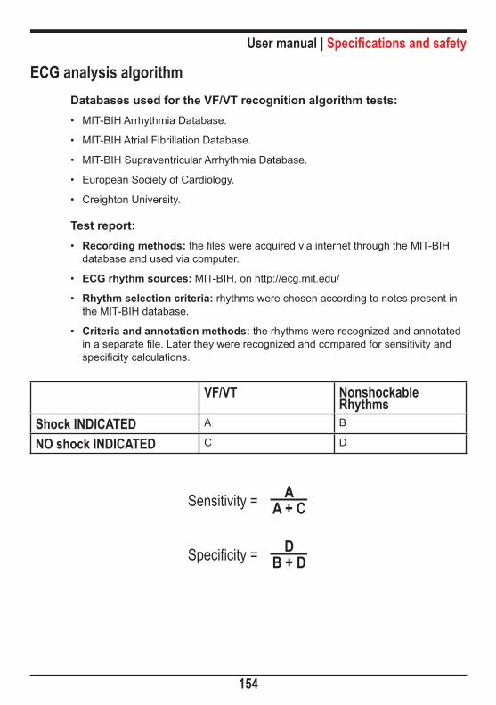
User manual | Specifications and safety
154
ECG analysis algorithmDatabases used for the VF/VT recognition algorithm tests:• MIT-BIH Arrhythmia Database.
• MIT-BIH Atrial Fibrillation Database.
• MIT-BIH Supraventricular Arrhythmia Database.
• European Society of Cardiology.
• Creighton University.
Test report:• Recording methods: the files were acquired via internet through the MIT-BIH
database and used via computer.
• ECG rhythm sources: MIT-BIH, on http://ecg.mit.edu/
• Rhythm selection criteria: rhythms were chosen according to notes present in the MIT-BIH database.
• Criteria and annotation methods: the rhythms were recognized and annotated in a separate file. Later they were recognized and compared for sensitivity and specificity calculations.
VF/VT Nonshockable Rhythms
Shock INDICATED A B
NO shock INDICATED C D
Sensitivity = AA + C
Specificity = DB + D

User manual | Specifications and safety
155
Sensitivity is the equipment’s percent ability to correctly identify a shockable rhythm.
Specificity is the equipment’s percent ability to correctly identify a nonshockable rhythm
A = True positive
B = False positive
C = False negative
D = True negative
A true positive (A) is the equipment’s ability, in measurement units, to correctly identify a shockable rhythm.
A false positive (B) is the equipment’s ability, in measurement units, to wrongly recognize a shockable rhythm.
A false negative (C) is the equipment’s ability, in measurement units, to wrongly recognize a nonshockable rhythm.
A true positive (D) is the equipment’s ability, in measurement units, to correctly recognize a nonshockable rhythm.
Values measured with the AED using the specified database:
VF/VT Nonshockable Rhythms
Shock INDICATED 329 23
NO shock INDICATED 10 454
Sensitivity = 97.05%
Specificity = 95,18%

User manual | Specifications and safety
156
Types of Arrhythmia analyzed:
Nonshockable:
• Sinus Rhythm/ Sinus Tachycardia/ Sinus Bradycardia;
• Atrial Tachycardia;
• Atrial Fibrillation;
• Atrial Flutter;
• Supraventricular Tachyarrhythmia;
• Normal Rhythm with Extrasystoles;
• Sinus Rhythm with Pacemaker;
• Asystole.
Shockable:
• Ventricular Tachycardia with several QRS amplitudes and widenings.
• Ventricular Fibrillation with several amplitudes.
Rhythm Classes SpecificationsShock - VF The CardioMax meets IEC 60601-2-4 requirements
for sensitivity > 90%.Shock - VT The CardioMax meets IEC 60601-2-4 requirements
for sensitivity > 75%.Nonshockable rhythms. The CardioMax meets IEC 60601-2-4 requirements
for specificity > 95%.
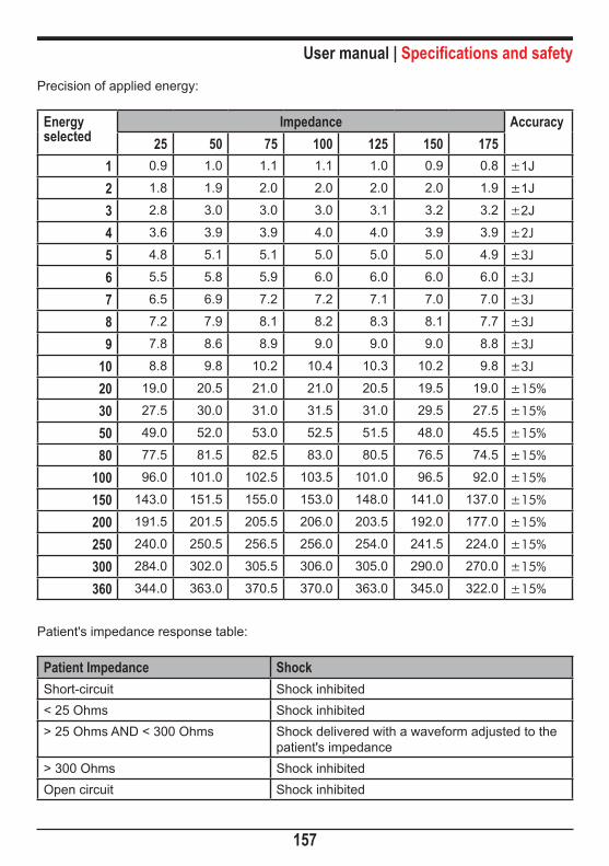
User manual | Specifications and safety
157
Precision of applied energy:
Energy selected
Impedance Accuracy25 50 75 100 125 150 175
1 0.9 1.0 1.1 1.1 1.0 0.9 0.8 ±1J
2 1.8 1.9 2.0 2.0 2.0 2.0 1.9 ±1J
3 2.8 3.0 3.0 3.0 3.1 3.2 3.2 ±2J
4 3.6 3.9 3.9 4.0 4.0 3.9 3.9 ±2J
5 4.8 5.1 5.1 5.0 5.0 5.0 4.9 ±3J
6 5.5 5.8 5.9 6.0 6.0 6.0 6.0 ±3J
7 6.5 6.9 7.2 7.2 7.1 7.0 7.0 ±3J
8 7.2 7.9 8.1 8.2 8.3 8.1 7.7 ±3J
9 7.8 8.6 8.9 9.0 9.0 9.0 8.8 ±3J
10 8.8 9.8 10.2 10.4 10.3 10.2 9.8 ±3J
20 19.0 20.5 21.0 21.0 20.5 19.5 19.0 ±15%
30 27.5 30.0 31.0 31.5 31.0 29.5 27.5 ±15%
50 49.0 52.0 53.0 52.5 51.5 48.0 45.5 ±15%
80 77.5 81.5 82.5 83.0 80.5 76.5 74.5 ±15%
100 96.0 101.0 102.5 103.5 101.0 96.5 92.0 ±15%
150 143.0 151.5 155.0 153.0 148.0 141.0 137.0 ±15%
200 191.5 201.5 205.5 206.0 203.5 192.0 177.0 ±15%
250 240.0 250.5 256.5 256.0 254.0 241.5 224.0 ±15%
300 284.0 302.0 305.5 306.0 305.0 290.0 270.0 ±15%
360 344.0 363.0 370.5 370.0 363.0 345.0 322.0 ±15%
Patient's impedance response table:
Patient Impedance ShockShort-circuit Shock inhibited< 25 Ohms Shock inhibited> 25 Ohms AND < 300 Ohms Shock delivered with a waveform adjusted to the
patient's impedance> 300 Ohms Shock inhibitedOpen circuit Shock inhibited

User manual | Specifications and safety
158
Values on the Y axis refer to voltage (volts) and values on the X axis refer to time (milliseconds)..
360J of energy at 25R impedance.
360J of energy at 50R impedance.
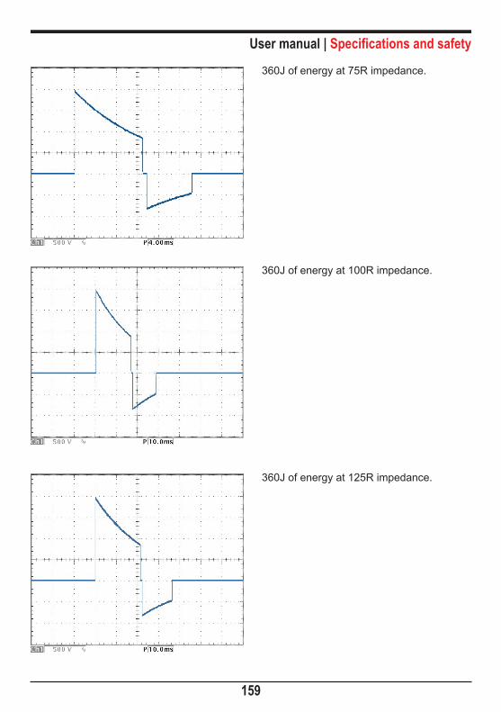
User manual | Specifications and safety
159
360J of energy at 75R impedance.
360J of energy at 100R impedance.
360J of energy at 125R impedance.

User manual | Specifications and safety
160
360J of energy at 150R impedance.
360J of energy at 175R impedance.
PacemakerWave form: Single-phase rectangular pulse.
Modes: Demand or fixed
Amplitude: Between 5 mA to 200 mA (resolution of 5 mA), precision 10%.
Pulse width: 20 ms (± 1ms)
Frequency: Between 30 ppm to 180 ppm (increments of 5 ppm), precision ± 2%.
User manual | Specifications and safety
161
Refractory period: 340 ms (between 30 to 80 ppm), 240 ms (between 90 to 180 ppm).
Maximum output voltage: 350 V
ECGInput: 3 or 5 lead ECG cable
10 lead ECG cable (optional)External padsMultifunctional pads
Supports up to 12 simultaneous derivations when equipped with optional cable
Electrode error: NO ELECTRODES and a trace line will appear on the display if there is a disconnected cable or electrode.
Low ECG amplitude or saturated ECG signal:
The “Searching for ECG Signal” message will appear on the screen or printer (electrocardiograph mode) when the ECG 10mm/mV amplitude is less than 2.4 mm peak-to peak (or sensitivity proportional).
Multifunction pads error: If an adhesive pad is disconnected, a trace line will appear on the display.
Range:
Precision:
15 to 350 BPM
± 1 BPM of 15 to 350 BPM
Rejection in common mode: Higher than 90 dB, measurement in compliance with the AAMI standards for heart monitors (EC 13).
Sensitivity: 5, 10, 15, 20, 30 e 40 mm/mV
CA line filter: 60 Hz or 50 Hz
ECG response frequency: Diagnostic mode (0.05 - 100 Hz)Monitor mode (1 - 40 Hz)
User manual | Specifications and safety
162
Patient isolation’s (defibrillation proof): ECG: CF type
SpO2: CF type
Physiological alarm: Alarm not lockedMinimum level (30-100)Maximum level (100-250)Visual indicationSound indicationSuspend sound indication functionSilence sound indication function
Technical alarm: Alarm not lockedVisual indicationSound indicationSuspend sound indication functionSilence sound indication function
Time to re-establish the ECG baseline after defibrillation: ≤ 3 seconds
ECG amplifiers impedance input: 4,7 Mohms (Mega ohms)
Pacemaker rejection stimulus: Pacemaker stimuli with widths between 0.1ms and 2ms
and amplitude between ± 2mV and ± 700mV are rejected in the counting of heartbeats. Concerning the overshoot, it complies with method A of the AAMI EC13:2002 standard.
Maximum amplitude of the T wave:
It meets the minimum recommended value of 1.2mV for the T wave amplitude rejection.
Accuracy of cardiac frequency in irregular rhythms:
It complies with the AAMI standard for ventricular bigeminy (FC = 40 bpm), slow alternating ventricular bigeminy (FC = 30 bpm); fast alternating ventricular bigeminy (FC = 120 bpm); bidirectional systoles (FC = 45 bpm).
Cardiac frequency response time:
80 to 120 bpm: maximum of 7 seconds80 to 40 bpm: maximum of 11 seconds

User manual | Specifications and safety
163
Tachycardia alarm time: 206 bpm (1 mV): 5 seconds206 bpm (0.5 mV): 5 seconds206 bpm (2 mV): 5 seconds195 bpm (2 mV): 5 seconds195 bpm (1 mV): 5 seconds195 bpm (4 mV): 5 seconds
NIBP - Non-Invasive Arterial PressureTechnique: Oscillometric
Adult range: Systolic: 40 to 260 mmHgMean: 26 to 220 mmHgDiastolic: 20 to 200 mmHg
Pediatric range: Systolic: 40 to 160 mmHgMean: 26 to 133 mmHgDiastolic: 20 to 120 mmHg
Neonatal range: Systolic: 40 to 130 mmHgMean: 26 to 110 mmHgDiastolic: 20 to 100 mmHg
Overpressure limit per software: Adult: 290 mmHg max
Neonatal: 145 mmHg max
Resolution:
Manual mode:
Automatic mode:
1 mmHg
One measurement
1, 2, 3, 4, 5, 10, 15, 30, 60 and 90 minutes
STAT mode: Maximum of consecutive measurements in 5 minutes.
SpO2 SpO2 range:
Pulse range:
0 to 100 %
30 to 250 BPM

User manual | Specifications and safety
164
SpO2's precision:
Pulse precision:
Scan:
± 2 % (70 to 100%). ± 3 % (50 a 69%)
± 2 BPM
12.5, 25 e 50 mm/s
Physiological alarm: Alarm not locked.Minimum level (40-95)Maximum level (45-100)Visual indicationSound indicationSuspend sound indication functionSilence sound indication function
Technical Alarm: Alarm not lockedVisual indicationSound indicationSuspend sound indication functionSilence sound indication function
PrinterType:
Weight:
Speed:
Paper size:
Thermal
0.4 Kg
12.5, 25 or 50 mm/s - 5% accuracy
48 mm (width)30 m (length)
RespirationTechnique: Transthoracic impedance
Range:
Precision:
3 to 150 breaths per minute
± 3 breaths per minute

User manual | Specifications and safety
165
Sensitivity: 1, 2, 3, 4, 5 and 6 X
Electrodes: RA-LA
Scans: 6.25, 12.5 and 25 mm/s
CapnographyWeight: 160 gr.
CO2 measurement interval:
Precision:
0 - 99 mmHg
± 2 mmHg (0 - 38 mmHg) ± 5% + 0.08% for each 1mmHg above 38 mmHg (39 – 99mmHg)
Calibration: 2 points
Start: 10 seconds to start the CO2 curve. Less than a minute for full functioning.
Consumption: 1.5 W
Format: Graphic
Memory: 72 hours - Non-volatile
Data Interval: 25 seconds
Graph format: A graph per vital sign.

22
166
Warranty Certificate
Instramed Indústria Médico Hospitalar Ltda. warrants the equipment described in this Certificate for 12 (twelve) months, starting from the delivery date. This warranty covers manufacturing or material defects that prevents proper functioning according to the specifications stated herein, as long as the conditions presented in this Certificate are respected.
During the warranty period, Instramed Indústria Médico Hospitalar Ltda. or its representative will repair or replace defective parts, at no expense to the equipment’s owner.
This warranty will no longer be valid if any damage occurs due to accident, natural disaster, improper connection to a power source, use distinct from that described in the User manual, or irregular working conditions.
Any attempt to violate, adjust or repair this equipment by individuals not authorized by Instramed Indústria Médico Hospitalar Ltda. will automatically invalidate this warranty. This also applies in case of alterations made to this contract, the fiscal receipt, or to the equipment’s serial number.
Instramed Indústria Médico Hospitalar Ltda. is not responsible for the improper use of this equipment, by people who are not familiar with its function or the techniques recommend for its proper use.
EQUIPMENT : ______________________________________________________
SERIAL NUMBER: __________________________________________________
PURCHASE DATE: __________________________________________________
FISCAL RECEIPT NUMBER: __________________________________________

www.instramed.com.br+55 (51) 3073 8200
Biphasic Monitor Defibrillator