User Manual UNO-3200G Series 電腦 -...
50
User Manual UNO-3200G Series 電腦 Intel® 6th Gen. Core TM i Processors Embedded Automation PC, with 2 or 4 PCIe/ PCI Extension Slots
Transcript of User Manual UNO-3200G Series 電腦 -...
User Manual
UNO-3200G Series 電腦
Intel® 6th Gen. CoreTM i Processors EmbeddedAutomation PC, with 2 or 4 PCIe/PCI Extension Slots
CopyrightThe documentation and the software included with this product are copyrighted 2017by Advantech Co., Ltd. All rights are reserved. Advantech Co., Ltd. reserves the rightto make improvements in the products described in this manual at any time withoutnotice. No part of this manual may be reproduced, copied, translated or transmittedin any form or by any means without the prior written permission of Advantech Co.,Ltd. Information provided in this manual is intended to be accurate and reliable. How-ever, Advantech Co., Ltd. assumes no responsibility for its use, nor for any infringe-ments of the rights of third parties, which may result from its use.
AcknowledgementsIntel® is trademarks of Intel Corporation.
Microsoft Windows and MS-DOS are registered trademarks of Microsoft Corp.
C&T is a trademark of Chips and Technologies, Inc.
All other product names or trademarks are properties of their respective owners.
Support
For more information on this and other Advantech products, please visit our websites
at: http://www.advantech.com
For technical support and service, please visit our support website at:
http://support.advantech.com/
This manual applies to the below model which is abbreviated as UNO-3200G seriesproducts in this article.
*Model number:
UNO-3283G
UNO-3285G
PN: 2003U32001 Edition 2
Printed in Taiwan March 2017
UNO-3200G Series User Manual ii
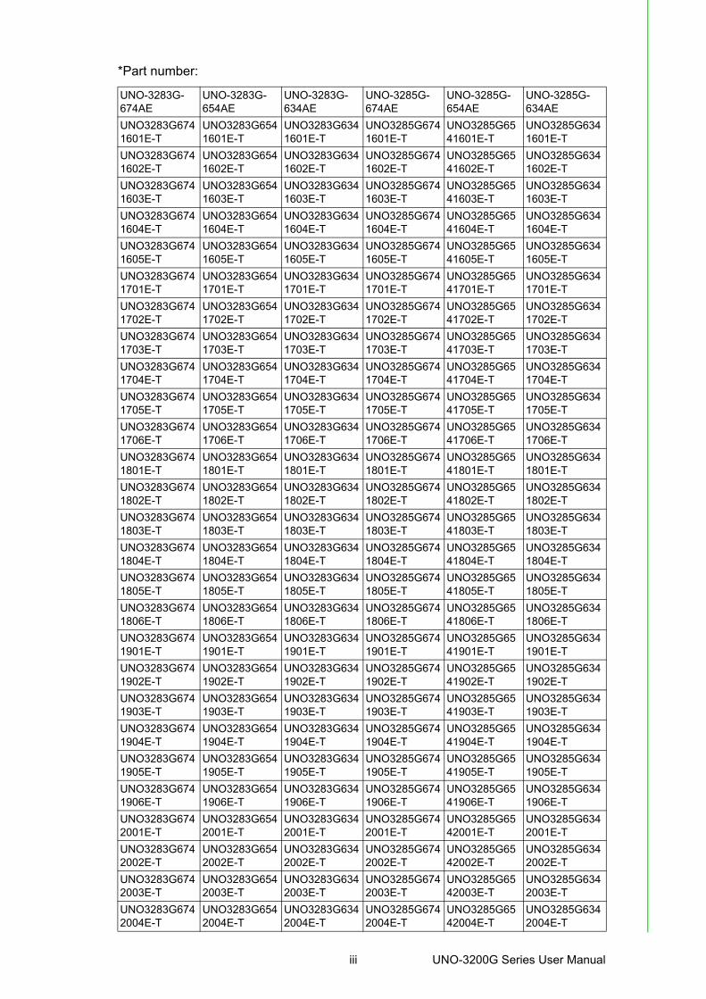
*Part number:
UNO-3283G-674AE
UNO-3283G-654AE
UNO-3283G-634AE
UNO-3285G-674AE
UNO-3285G-654AE
UNO-3285G-634AE
UNO3283G6741601E-T
UNO3283G6541601E-T
UNO3283G6341601E-T
UNO3285G6741601E-T
UNO3285G6541601E-T
UNO3285G6341601E-T
UNO3283G6741602E-T
UNO3283G6541602E-T
UNO3283G6341602E-T
UNO3285G6741602E-T
UNO3285G6541602E-T
UNO3285G6341602E-T
UNO3283G6741603E-T
UNO3283G6541603E-T
UNO3283G6341603E-T
UNO3285G6741603E-T
UNO3285G6541603E-T
UNO3285G6341603E-T
UNO3283G6741604E-T
UNO3283G6541604E-T
UNO3283G6341604E-T
UNO3285G6741604E-T
UNO3285G6541604E-T
UNO3285G6341604E-T
UNO3283G6741605E-T
UNO3283G6541605E-T
UNO3283G6341605E-T
UNO3285G6741605E-T
UNO3285G6541605E-T
UNO3285G6341605E-T
UNO3283G6741701E-T
UNO3283G6541701E-T
UNO3283G6341701E-T
UNO3285G6741701E-T
UNO3285G6541701E-T
UNO3285G6341701E-T
UNO3283G6741702E-T
UNO3283G6541702E-T
UNO3283G6341702E-T
UNO3285G6741702E-T
UNO3285G6541702E-T
UNO3285G6341702E-T
UNO3283G6741703E-T
UNO3283G6541703E-T
UNO3283G6341703E-T
UNO3285G6741703E-T
UNO3285G6541703E-T
UNO3285G6341703E-T
UNO3283G6741704E-T
UNO3283G6541704E-T
UNO3283G6341704E-T
UNO3285G6741704E-T
UNO3285G6541704E-T
UNO3285G6341704E-T
UNO3283G6741705E-T
UNO3283G6541705E-T
UNO3283G6341705E-T
UNO3285G6741705E-T
UNO3285G6541705E-T
UNO3285G6341705E-T
UNO3283G6741706E-T
UNO3283G6541706E-T
UNO3283G6341706E-T
UNO3285G6741706E-T
UNO3285G6541706E-T
UNO3285G6341706E-T
UNO3283G6741801E-T
UNO3283G6541801E-T
UNO3283G6341801E-T
UNO3285G6741801E-T
UNO3285G6541801E-T
UNO3285G6341801E-T
UNO3283G6741802E-T
UNO3283G6541802E-T
UNO3283G6341802E-T
UNO3285G6741802E-T
UNO3285G6541802E-T
UNO3285G6341802E-T
UNO3283G6741803E-T
UNO3283G6541803E-T
UNO3283G6341803E-T
UNO3285G6741803E-T
UNO3285G6541803E-T
UNO3285G6341803E-T
UNO3283G6741804E-T
UNO3283G6541804E-T
UNO3283G6341804E-T
UNO3285G6741804E-T
UNO3285G6541804E-T
UNO3285G6341804E-T
UNO3283G6741805E-T
UNO3283G6541805E-T
UNO3283G6341805E-T
UNO3285G6741805E-T
UNO3285G6541805E-T
UNO3285G6341805E-T
UNO3283G6741806E-T
UNO3283G6541806E-T
UNO3283G6341806E-T
UNO3285G6741806E-T
UNO3285G6541806E-T
UNO3285G6341806E-T
UNO3283G6741901E-T
UNO3283G6541901E-T
UNO3283G6341901E-T
UNO3285G6741901E-T
UNO3285G6541901E-T
UNO3285G6341901E-T
UNO3283G6741902E-T
UNO3283G6541902E-T
UNO3283G6341902E-T
UNO3285G6741902E-T
UNO3285G6541902E-T
UNO3285G6341902E-T
UNO3283G6741903E-T
UNO3283G6541903E-T
UNO3283G6341903E-T
UNO3285G6741903E-T
UNO3285G6541903E-T
UNO3285G6341903E-T
UNO3283G6741904E-T
UNO3283G6541904E-T
UNO3283G6341904E-T
UNO3285G6741904E-T
UNO3285G6541904E-T
UNO3285G6341904E-T
UNO3283G6741905E-T
UNO3283G6541905E-T
UNO3283G6341905E-T
UNO3285G6741905E-T
UNO3285G6541905E-T
UNO3285G6341905E-T
UNO3283G6741906E-T
UNO3283G6541906E-T
UNO3283G6341906E-T
UNO3285G6741906E-T
UNO3285G6541906E-T
UNO3285G6341906E-T
UNO3283G6742001E-T
UNO3283G6542001E-T
UNO3283G6342001E-T
UNO3285G6742001E-T
UNO3285G6542001E-T
UNO3285G6342001E-T
UNO3283G6742002E-T
UNO3283G6542002E-T
UNO3283G6342002E-T
UNO3285G6742002E-T
UNO3285G6542002E-T
UNO3285G6342002E-T
UNO3283G6742003E-T
UNO3283G6542003E-T
UNO3283G6342003E-T
UNO3285G6742003E-T
UNO3285G6542003E-T
UNO3285G6342003E-T
UNO3283G6742004E-T
UNO3283G6542004E-T
UNO3283G6342004E-T
UNO3285G6742004E-T
UNO3285G6542004E-T
UNO3285G6342004E-T
iii UNO-3200G Series User Manual
Product Warranty (2 years)Advantech warrants to you, the original purchaser, that each of its products will befree from defects in materials and workmanship for two years from the date of pur-chase.
This warranty does not apply to any products which have been repaired or altered bypersons other than repair personnel authorized by Advantech, or which have beensubject to misuse, abuse, accident or improper installation. Advantech assumes noliability under the terms of this warranty as a consequence of such events.
Because of Advantech’s high quality-control standards and rigorous testing, most ofour customers never need to use our repair service. If an Advantech product is defec-tive, it will be repaired or replaced at no charge during the warranty period. For out-of-warranty repairs, you will be billed according to the cost of replacement materials,service time and freight. Please consult your dealer for more details.
If you think you have a defective product, follow these steps:
1. Collect all the information about the problem encountered. (For example, CPU speed, Advantech products used, other hardware and software used, etc.) Note anything abnormal and list any onscreen messages you get when the problem occurs.
2. Call your dealer and describe the problem. Please have your manual, product, and any helpful information readily available.
3. If your product is diagnosed as defective, obtain an RMA (return merchandize authorization) number from your dealer. This allows us to process your return more quickly.
4. Carefully pack the defective product, a fully-completed Repair and Replacement Order Card and a photocopy proof of purchase date (such as your sales receipt) in a shippable container. A product returned without proof of the purchase date is not eligible for warranty service.
5. Write the RMA number visibly on the outside of the package and ship it prepaid to your dealer.
Declaration of Conformity
CE
This product has passed the CE test for environmental specifications when shieldedcables are used for external wiring. We recommend the use of shielded cables. Thiskind of cable is available from Advantech. Please contact your local supplier forordering information.
FCC Class A
Note: This equipment has been tested and found to comply with the limits for a ClassA digital device, pursuant to part 15 of the FCC Rules. These limits are designed toprovide reasonable protection against harmful interference when the equipment isoperated in a commercial environment. This equipment generates, uses, and canradiate radio frequency energy and, if not installed and used in accordance with theinstruction manual, may cause harmful interference to radio communications. Opera-tion of this equipment in a residential area is likely to cause harmful interference inwhich case the user will be required to correct the interference at his own expense.
警告使用者:這是甲類資訊產品,在居住的環境中使用時, 可能會造成射頻干擾,在這種情況下,使用者會被要求採取某些適當對策。
UNO-3200G Series User Manual iv
Technical Support and Assistance1. Visit the Advantech web site at http://support.advantech.com where you can
find the latest information about the product.2. Contact your distributor, sales representative, or Advantech's customer service
center for technical support if you need additional assistance. Please have the following information ready before you call:– Product name and serial number– Description of your peripheral attachments– Description of your software (operating system, version, application software,
etc.)– A complete description of the problem– The exact wording of any error messages
Safety Precaution - Static ElectricityFollow these simple precautions to protect yourself from harm and the products fromdamage.
To avoid electrical shock, always disconnect the power from your PC chassis before you work on it. Don't touch any components on the CPU card or other cards while the PC is on.
Disconnect power before making any configuration changes. The sudden rush of power as you connect a jumper or install a card may damage sensitive elec-tronic components.
v UNO-3200G Series User Manual
Safety Instructions1. Read these safety instructions carefully.2. Keep this User Manual for later reference.3. Disconnect this equipment from any AC outlet before cleaning. Use a damp
cloth. Do not use liquid or spray detergents for cleaning.4. For plug-in equipment, the power outlet socket must be located near the equip-
ment and must be easily accessible.5. Keep this equipment away from humidity.6. Put this equipment on a reliable surface during installation. Dropping it or letting
it fall may cause damage.7. The openings on the enclosure are for air convection. Protect the equipment
from overheating. DO NOT COVER THE OPENINGS.8. Make sure the voltage of the power source is correct before connecting the
equipment to the power outlet.9. Position the power cord so that people cannot step on it. Do not place anything
over the power cord.10. All cautions and warnings on the equipment should be noted.11. If the equipment is not used for a long time, disconnect it from the power source
to avoid damage by transient overvoltage.12. Never pour any liquid into an opening. This may cause fire or electrical shock.13. Never open the equipment. For safety reasons, the equipment should be
opened only by qualified service personnel.14. If one of the following situations arises, get the equipment checked by service
personnel: The power cord or plug is damaged. Liquid has penetrated into the equipment. The equipment has been exposed to moisture. The equipment does not work well, or you cannot get it to work according to the
user's manual. The equipment has been dropped and damaged. The equipment has obvious signs of breakage.15. DO NOT LEAVE THIS EQUIPMENT IN AN ENVIRONMENT WHERE THE
STORAGE TEMPERATURE MAY GO BELOW -20° C (-4° F) OR ABOVE 60° C (140° F). THIS COULD DAMAGE THE EQUIPMENT. THE EQUIPMENT SHOULD BE IN A CONTROLLED ENVIRONMENT.
16. CAUTION: DANGER OF EXPLOSION IF BATTERY IS INCORRECTLY REPLACED. REPLACE ONLY WITH THE SAME OR EQUIVALENT TYPE RECOMMENDED BY THE MANUFACTURER, DISCARD USED BATTERIES ACCORDING TO THE MANUFACTURER'S INSTRUCTIONS.
17. The sound pressure level at the operator's position according to IEC 704-1:1982 is no more than 70 dB (A).
DISCLAIMER: This set of instructions is given according to IEC 704-1. Advantechdisclaims all responsibility for the accuracy of any statements contained herein.
UNO-3200G Series User Manual vi
安全指示1. 請仔細閱讀此安全操作說明。
2. 請妥善保存此用戶手冊供日後參考。
3. 用濕抹布清洗設備前,請確認拔除電源線。請勿使用液體或去污噴霧劑清洗設備。
4. 對於使用電源線的設備,設備周圍必須有容易接觸到的電源插座。
5. 請勿在潮濕環境中試用設備。
6. 請在安裝前確保設備放置在可靠的平面上,意外摔落可能會導致設備損壞。
7. 設備機殼的開孔適用於空氣對,從而防止設備過熱。請勿覆蓋開孔。
8. 當您連接設備到電源插座前,請確認電源插座的電壓符合要求。
9. 請將電源線佈置在人們不易絆倒的位置,請勿在電源線上覆蓋任何雜物。
10. 請注意設備上所有的警告標示。
11. 如果長時間不使用設備,請拔除與電源插座的連結,避免設備被超標的電壓波動損壞。
12. 請勿讓任何液體流入通風口,以免引起火灾或短路。
13. 請勿自行打開設備。為了確保您的安全,請透過經認證的工程師來打開設備。
14. 如遇下列情况,請由專業人員維修:
電源線或插頭損壞;
設備內部有液體流入;
設備曾暴露在過度潮濕環境中使用;
設備無法正常工作,或您無法透過用戶手冊來正常工作;
設備摔落或損壞;
設備有明顯外觀損;
15. 請勿將設備放置在超出建議溫度範圍的環境,即不要低於 ‐20 ℃ (‐4 ℉)或高於 60℃ (140 ℉),否則可能會造成設備損壞。
16. 注意:若電池更換不正確,將有爆炸危險。因此,只可以使用製造商推薦的同一種或者同等型號的電池進行替換。請按照製造商的指示處理舊電池。
17. 本產品於國內裝置使用時,其電源僅限使用機架電源模組所提供直流電源輸入,不得使用交流電源及附加其他電源轉換裝置提供電源,其電源輸入電壓及電流請依說明書規定使用。
18. 根據 IEC 704‐1:1982 規定,操作員所在位置音量不可高於 70 分貝。
19. 限制區域:請勿將設備安裝於限制區域使用。
20. 免責聲明:請安全訓示符合 IEC 704‐1 要求。研華公司對其內容之準確性不承擔任何法律責任。
vii UNO-3200G Series User Manual
RoHS Claim
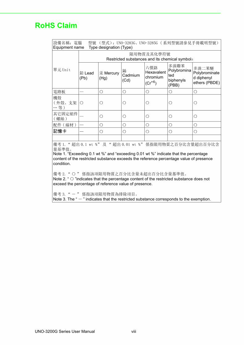
設備名稱:電腦 型號 (型式):UNO-3283G、UNO-3285G ( 系列型號請參見手冊載明型號)Equipment name Type designation (Type)
單元 Unit
限用物質及其化學符號Restricted substances and its chemical symbols
鉛 Lead(Pb)
汞 Mercury(Hg)
鎘Cadmium(Cd)
六價鉻Hexavalent chromium
(Cr+6)
多溴聯苯Polybrominated biphenyls(PBB)
多溴二苯醚Polybrominated diphenyl ethers (PBDE)
電路板 — ○ ○ ○ ○ ○
機殼( 外殼、支架… 等 )
○ ○ ○ ○ ○ ○
其它固定組件 ( 螺絲 )
— ○ ○ ○ ○ ○
配件 ( 線材 ) — ○ ○ ○ ○ ○
記憶卡 — ○ ○ ○ ○ ○
備考 1.“ 超出 0.1 wt %” 及 “ 超出 0.01 wt %” 係指限用物質之百分比含量超出百分比含量基準值。Note 1. “Exceeding 0.1 wt %” and “exceeding 0.01 wt %” indicate that the percentage content of the restricted substance exceeds the reference percentage value of presence condition.
備考 2.“ ○ ” 係指該項限用物質之百分比含量未超出百分比含量基準值。Note 2. “ ○ ”indicates that the percentage content of the restricted substance does not exceed the percentage of reference value of presence.
備考 3.“ - ” 係指該項限用物質為排除項目。Note 3. The “ - ” indicates that the restricted substance corresponds to the exemption.
UNO-3200G Series User Manual viii
Contents
Chapter 1 Overview...............................................11.1 Introduction ............................................................................................... 21.2 Hardware Specifications ........................................................................... 2
1.2.1 General ......................................................................................... 21.3 System Hardware...................................................................................... 3
1.3.1 I/O Interfaces ................................................................................ 31.3.2 Environment.................................................................................. 41.3.3 Expansion Board (Optional).......................................................... 4
1.4 Safety Precautions .................................................................................... 41.5 Chassis Dimensions.................................................................................. 5
Figure 1.1 UNO-3283G Dimensions............................................ 5Figure 1.2 UNO-3285G Dimensions............................................ 5
1.6 Accessories............................................................................................... 6
Chapter 2 Hardware Functionality.......................72.1 Introduction ............................................................................................... 8
Figure 2.1 UNO-3283G Front View ............................................. 8Figure 2.2 UNO-3285G Front View ............................................. 8
2.2 Serial Interface (COM1/COM2)................................................................. 9Figure 2.3 Serial Interface (COM1, COM2) ................................. 9
2.2.1 RS-232/422/485 Interface (COM1 & COM2) ................................ 92.2.2 To switch the internal SW1/SW2/SW3 according to the placement
10Figure 2.4 COM setting.............................................................. 10Figure 2.5 COM1 RS422 Rx termination (pin1-pin2)................. 10Figure 2.6 COM2 RS422 Rx termination (pin3-pin4)................. 11
2.3 LAN: Ethernet Connector ........................................................................ 112.4 Power Connector .................................................................................... 112.5 USB Connector ....................................................................................... 112.6 Display Connector................................................................................... 112.7 RTC Battery ............................................................................................ 122.8 Power Button/Power Management ......................................................... 12
2.8.1 Power mode switch..................................................................... 12Figure 2.7 AT/ATX Adjustment .................................................. 12
2.9 PCI Express Mini Card Socket................................................................ 13Figure 2.8 PCIE mini card sockets placement........................... 13
2.9.1 iDoor Expansion Slot .................................................................. 132.10 PCIe/PCI Slot .......................................................................................... 132.11 SATA HDD/SSD Drive ............................................................................ 14
Figure 2.9 SATA Mode Selection .............................................. 14Figure 2.10Detecting a RAID configuration ................................ 14Figure 2.11Creating a RAID Volume .......................................... 15
2.12 Audio Jack............................................................................................... 152.13 LED Indicators......................................................................................... 15
Chapter 3 Initial Setup ........................................173.1 Connecting Power................................................................................... 18
Figure 3.1 Power Connector...................................................... 183.2 Inserting an iDoor Module ....................................................................... 183.3 Installing a Hard Disk .............................................................................. 203.4 Installing an Interface Card or CFast Card.............................................. 21
ix UNO-3200G Series User Manual
3.5 Mounting UNO-3200G Series ................................................................. 22Figure 3.2 Stand Mount ............................................................. 22Figure 3.3 Enclosure Mount ...................................................... 22Figure 3.4 Wall Mount (01) ........................................................ 23Figure 3.5 Wall Mount (02) ........................................................ 23
Appendix A System Settings and Pin Assignments25
A.1 System I/O Address and Interrupt Assignment....................................... 26Table A.1: Interrupt Assignments .............................................. 26
A.2 Board Connectors and Switches............................................................. 27Figure A.1 Bottom view of System Board .................................. 27
A.3 Function of connectors & switches ......................................................... 28Table A.2: Connectors on System board................................... 28
A.4 Audio (Pin header) .................................................................................. 29Table A.3: CN9 Audio ................................................................ 29
A.5 COM1/COM2 .......................................................................................... 30Table A.4: COM POER Pin Definition........................................ 30
A.6 COM3/COM4 .......................................................................................... 30Table A.5: RS-232 Serial Port Pin Assignments........................ 30
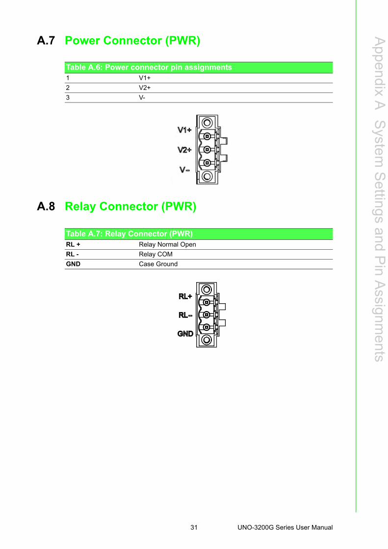
A.7 Power Connector (PWR) ........................................................................ 31Table A.6: Power connector pin assignments ........................... 31
A.8 Relay Connector (PWR) ......................................................................... 31Table A.7: Relay Connector (PWR)........................................... 31
A.9 SW7 Power Switch ................................................................................. 32Table A.8: SW4 Power Switch................................................... 32
A.10 CN19/CN20 Mini PCIE............................................................................ 33Table A.9: CN19/CN20 Mini PCIE ............................................. 33
A.11 CN19 mSATA ......................................................................................... 35Table A.10:CN19 mSATA........................................................... 35
A.12 VO1 reserve for power output, the voltage is same as power input ....... 37Table A.11:VO1 reserve for power output, the voltage is same as
power input............................................................... 37A.13 CN1 Internal 12V power for PCI/PCIe .................................................... 38
Table A.12:CN1 Internal 12V power for PCI/PCIe...................... 38
UNO-3200G Series User Manual x
Chapter 1
1 OverviewThis chapter provides an overviewof UNO-3200G series' specifica-tions.
Sections include:
Introduction
Hardware specification
Safety precautions
Chassis dimensions
Accessories
1.1 IntroductionHigh performing UNO-3200G models are configured with high-performance IntelGen.6 Core i, which offers users maximum flexibility, two displays, six USB 3.0 ports,two mPCIe sockets, and expansion via PCIe/PCI slots and iDoor expansion, iDoortechnology supports automation feature extensions such as industry Fieldbus com-munication, POE, COM & Digital I/O. The UNO-3200G has a variety of convenientdesigns, captive thumb screws, dual hot-Swappable HDD/SSD slots, and exchange-able RTC battery that can facilitate maintenance work, and preventing unstable con-ditions like power drops.
1.2 Hardware Specifications
1.2.1 General Certification:
– CE, FCC, UL, CCC, BSMI Dimensions (W×D×H):
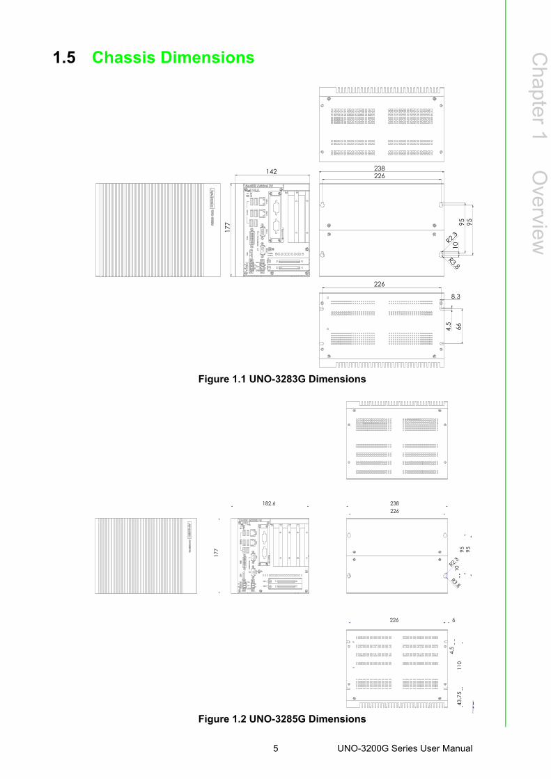
– UNO-3283G: 142 x 238 x 177 mm (5.6'' x 9.3'' x 6.9'') – UNO-3285G: 182 x 238 x 177 mm (7.2" x 9.3" x 6.9")
Mounting: Wall mount, Stand mount, Enclosure mount Power Consumption: 30 W (Typical, no card added) Power Requirements: 10Vdc-36Vdc, support AT/ATX power mode BIOS AT
simulation mode (support system reboot automatically after power recovery) Weight: 4.5 kg OS Support: Windows7/8, WES7, Win10 Enterprise LTSB, AdvLinuxTu System Design: Fanless
UNO-3200G Series User Manual 2
Chapter 1
Overview
1.3 System Hardware CPU:
– UNO-3283G-674AE: Intel Core® i7-6822EQ (8M Cache, 2.0GHz)– UNO-3283G-654AE: Intel Core® i5-6442EQ (6M Cache, 1.9GHz)– UNO-3283G-634AE: Intel Core® i3-6102E (3M Cache, 1.9GHz)– UNO-3285G-674AE: Intel Core® i7-6822EQ (8M Cache, 2.0GHz)– UNO-3285G-654AE: Intel Core® i5-6442EQ (6M Cache, 1.9GHz)– UNO-3285G-634AE: Intel Core® i3-6102E (3M Cache, 1.9GHz)
Memory: 8G DDR4 built-in Indicators: LEDs for Power, Battery, HDD, COM (Tx/Rx) Storage: 2 × 2.5" SATA HDD/SSD bays, support 9.5mm height & SATA Gen3.0,
1 x mSATA slot, 1 x CFast slot Watchdog Timer: 256 levels time interval, programmable from 0 to 255 sec Expansion Slots:
– UNO-3283G: 2 Full-size mPCIe, 1 x PCIex16, 1 x PCI (Optional by project: 2 x PCIex8 or 2 x PCI)
– UNO-3285G: 2 Full-size mPCIe, 2 x PCIex8, 2 x PCI (Optional by project: 4 x PCI)
PCIE max speed is 5 GB; PCI max speed is 66MHz; system can provide typical 10W for each PCI/PCIE slot, Max 20W for single slot condition:
Each PCI/PCIE slot can support below power rail:
1.3.1 I/O Interfaces Serial Ports: 2 x RS-232/422/485, DB9, auto flow control, 50 ~ 115.2 kbps LAN Ports: 2 x RJ45, 10/100/1000 Mbps IEEE 802.3u 1000Base-T Fast Ether-
net USB Ports: 6 x USB 3.0 Ports Displays: 1 x HDMI, supports 1920 x 1080 @ 24 Hz 24 bpp; 1 x DVI-I, supports
1920 x 1080 @ 60 Hz 24 bpp & 2 independent displays Power Connector: 1 x 3 pin, terminal block
Model Slot1 Power Slot2 Power Slot3 Power Slot4 PowerTotal Power Limitation
UNO-3283G
Typical 10W, Max 20W
Typical 10W, Max 20W
N/A N/AMax <40W (Note1)
UNO-3285G
Typical 10W, Max 20W
Typical 10W, Max 20W
Typical 10W, Max 20W
Typical 10W, Max 20W
Max <40W (Note1)
Slot type A: 3.3V B: 5V C: 12V D:-12V Note
PCI slottypical 3.03AMax 6.06A
typical 2AMax 4A
typical 0.83AMax 1.66A
Max 0.5AA+B+C+D, total power<20W
PCIE slottypical 3.03AMax 6.06A
typical 2AMax 4A
typical 0.83AMax 1.66A
N/AA+B+C, total power<20W
Note! Total power consumption combined on PCI and PCIe slots should be less than 40 Watt.
3 UNO-3200G Series User Manual
1.3.2 Environment Relative Humidity: 95% @40°C (Non-condensing) Operating Temperature: -20 ~ 60°C (-4 ~ 140°F) @ 5 ~ 85% RH with 0.7m/s airflow (Safety certification: -20 ~ 45°C (-4 ~ 113°F) )
Storage Temperature: - 40 ~ 85°C (-104 ~ 185°F) Shock Protection:
– IEC 60068-2-27– 50 G, half sine, 11 ms
Vibration Protection:– IEC 60068-2-64 (Random 1 Oct./min, 1hr/axis.)– 1.5 Grms @ 5 ~ 500 Hz with HDD– 4Grms @ 5 ~ 500 Hz with SSD
1.3.3 Expansion Board (Optional) UNO-3283G:
– 1x PCIex16, 1 x PCI slots– 2x PCIex8 slots– 2x PCI slots
UNO-3285G:– 2x PCIex8, 2x PCI slots– 4x PCI slots.
1.4 Safety PrecautionsThe following sections tell how to make each connection. In most cases, you will sim-
ply need to connect a standard cable.
Warning! Always disconnect the power cord from your chassis whenever you are working on it. Do not connect while the power is on. A sudden rush of power can damage sensitive electronic components. Only experienced electronics personnel should open the chassis.
Caution! Always ground yourself to remove any static electric charge before touching UNO-3200G series. Modern electronic devices are very sensi-tive to static electric charges. Use a grounding wrist strap at all times. Place all electronic components on a static-dissipative surface or in a static-shielded bag.
UNO-3200G Series User Manual 4
Chapter 1
Overview
1.5 Chassis Dimensions
Figure 1.1 UNO-3283G Dimensions
Figure 1.2 UNO-3285G Dimensions
142
177
226
9510
238
9566
226
177
226
9510
238
95110
226 6
DITO
5 UNO-3200G Series User Manual
1.6 AccessoriesPlease refer to the below accessories list for UNO-3200G series.
2 × 3-pin plug-in block for power wiring & relay control 1 × Warranty card 1 × UNO series driver &utility DVD-ROM 1 × DVI- VGA connector 2 x Wall mount kit 12 x M3*5L screws for fastening wall mount kit and HDD/SSD 4 x screws for fastening mPCIe modules English Quick Start Guide Simplified Chinese manual
UNO-3200G Series User Manual 6
Chapter 2
2 Hardware FunctionalityThis chapter shows how to setup UNO-3200G series' hardware functions, including connecting peripherals, setting switches and indicators.Sections include:
Peripherals
RS-232/422/485 Interface
LAN / Ethernet Connector
Power Connector
Mini PCIe Socket
Audio Connector
USB Connector
DVI-I/HDMI Display Connector
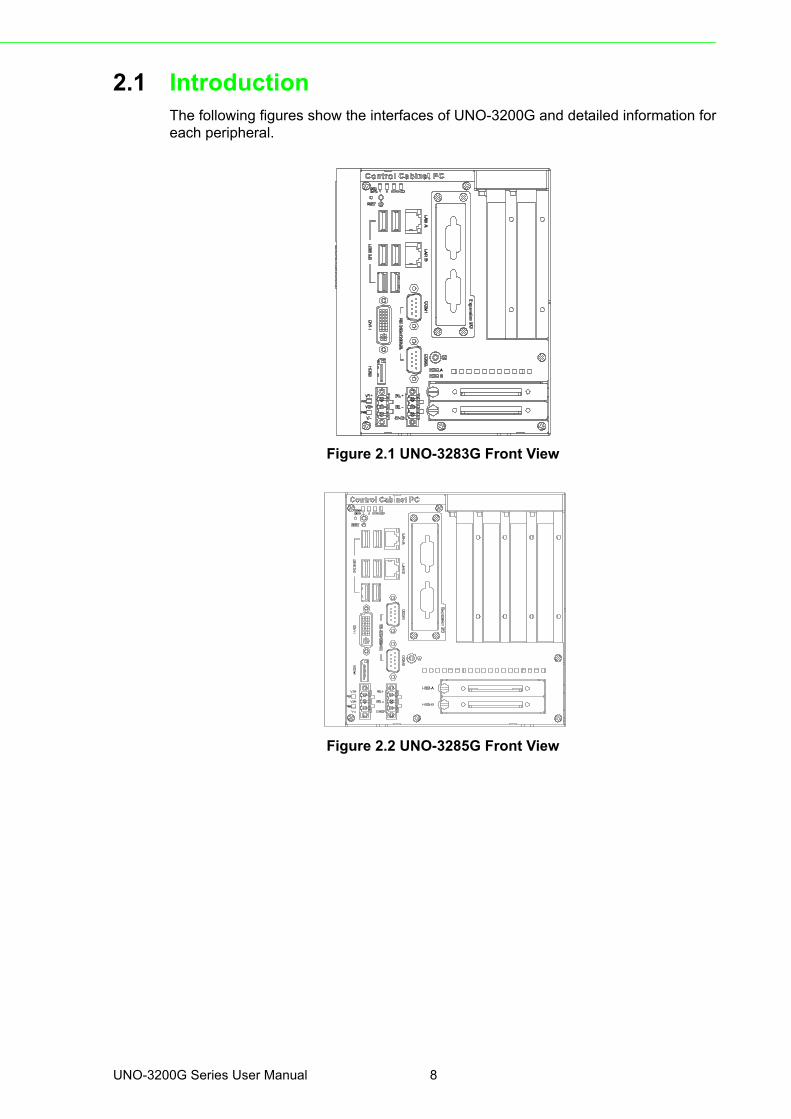
2.1 IntroductionThe following figures show the interfaces of UNO-3200G and detailed information foreach peripheral.
Figure 2.1 UNO-3283G Front View
Figure 2.2 UNO-3285G Front View
UNO-3200G Series User Manual 8
Chapter 2
Hardw
areF
unctionality
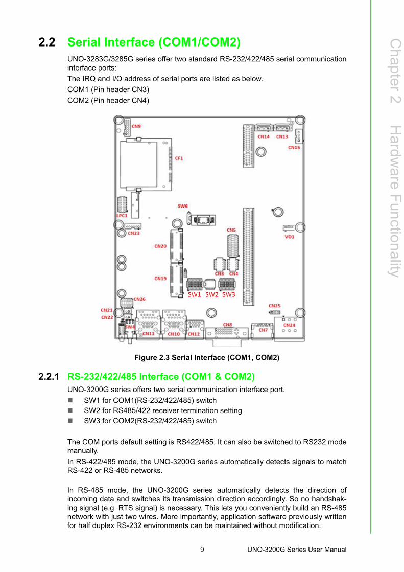
2.2 Serial Interface (COM1/COM2)UNO-3283G/3285G series offer two standard RS-232/422/485 serial communicationinterface ports:
The IRQ and I/O address of serial ports are listed as below.
COM1 (Pin header CN3)
COM2 (Pin header CN4)
Figure 2.3 Serial Interface (COM1, COM2)
2.2.1 RS-232/422/485 Interface (COM1 & COM2)UNO-3200G series offers two serial communication interface port.
SW1 for COM1(RS-232/422/485) switch SW2 for RS485/422 receiver termination setting SW3 for COM2(RS-232/422/485) switch
The COM ports default setting is RS422/485. It can also be switched to RS232 modemanually.
In RS-422/485 mode, the UNO-3200G series automatically detects signals to matchRS-422 or RS-485 networks.
In RS-485 mode, the UNO-3200G series automatically detects the direction ofincoming data and switches its transmission direction accordingly. So no handshak-ing signal (e.g. RTS signal) is necessary. This lets you conveniently build an RS-485network with just two wires. More importantly, application software previously writtenfor half duplex RS-232 environments can be maintained without modification.
9 UNO-3200G Series User Manual
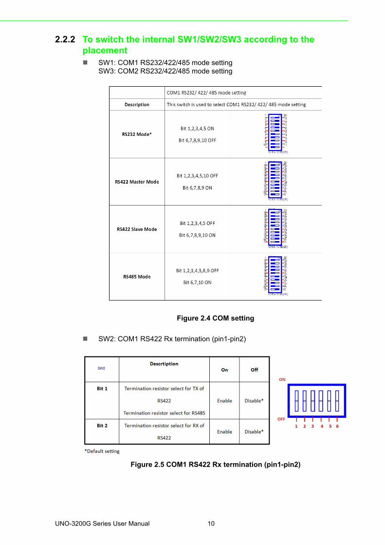
2.2.2 To switch the internal SW1/SW2/SW3 according to the placement SW1: COM1 RS232/422/485 mode setting
SW3: COM2 RS232/422/485 mode setting
Figure 2.4 COM setting
SW2: COM1 RS422 Rx termination (pin1-pin2)
Figure 2.5 COM1 RS422 Rx termination (pin1-pin2)
UNO-3200G Series User Manual 10
Chapter 2
Hardw
areF
unctionality
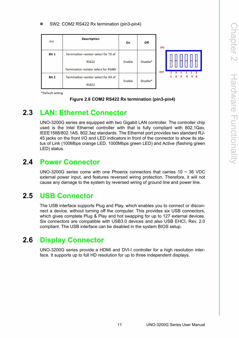
SW2: COM2 RS422 Rx termination (pin3-pin4)
Figure 2.6 COM2 RS422 Rx termination (pin3-pin4)
2.3 LAN: Ethernet Connector UNO-3200G series are equipped with two Gigabit LAN controller. The controller chipused is the Intel Ethernet controller with that is fully compliant with 802.1Qav,IEEE1588/802.1AS, 802.3az standards. The Ethernet port provides two standard RJ-45 jacks on the front I/O and LED indicators in front of the connector to show its sta-tus of Link (100Mbps orange LED, 1000Mbps green LED) and Active (flashing greenLED) status.
2.4 Power Connector UNO-3200G series come with one Phoenix connectors that carries 10 ~ 36 VDCexternal power input, and features reversed wiring protection. Therefore, it will notcause any damage to the system by reversed wiring of ground line and power line.
2.5 USB Connector The USB interface supports Plug and Play, which enables you to connect or discon-nect a device, without turning off the computer. This provides six USB connectors,which gives complete Plug & Play and hot swapping for up to 127 external devices.Six connectors are compatible with USB3.0 devices and also USB EHCI, Rev. 2.0compliant. The USB interface can be disabled in the system BIOS setup.
2.6 Display ConnectorUNO-3200G series provide a HDMI and DVI-I controller for a high resolution inter-face. It supports up to full HD resolution for up to three independent displays.
11 UNO-3200G Series User Manual
2.7 RTC Battery The RTC Battery to ensure the setting in BIOS and system clock can be kept, evenwith power disconnected for a short time.
Type: BR2032 (Using CR2032 is NOT recommended) Output Voltage: 3 VDC
2.8 Power Button/Power Management Press the “PWR” button to power on or power off (ATX type). This product supportsthe ACPI (Advanced Configuration and Power Interface). As well as power on/off, itsupports multiple suspend modes, such as Power on Suspend (S1), Suspend toRAM (S3), and Suspend to Disk (S4).
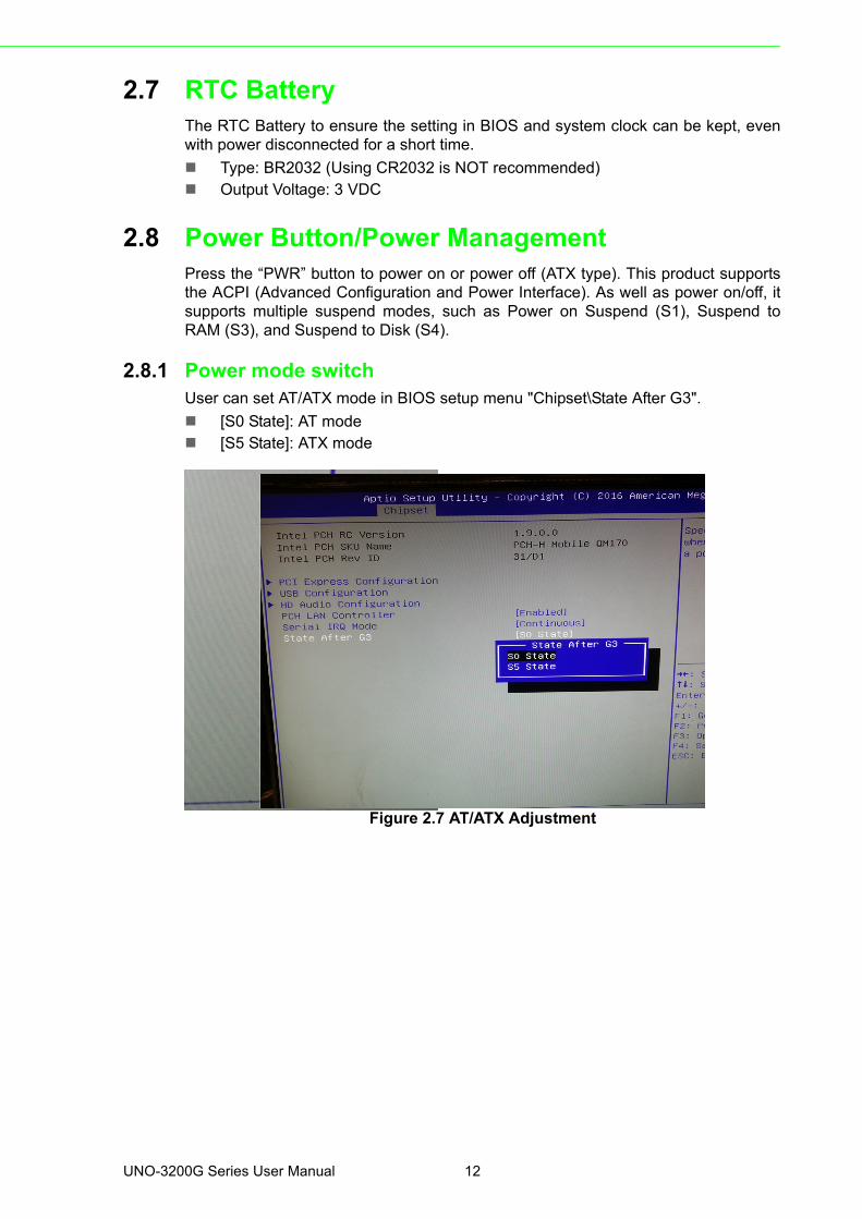
2.8.1 Power mode switchUser can set AT/ATX mode in BIOS setup menu "Chipset\State After G3".
[S0 State]: AT mode [S5 State]: ATX mode
Figure 2.7 AT/ATX Adjustment
UNO-3200G Series User Manual 12
Chapter 2
Hardw
areF
unctionality
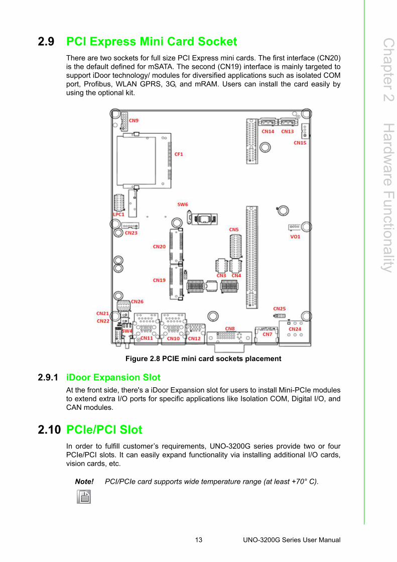
2.9 PCI Express Mini Card SocketThere are two sockets for full size PCI Express mini cards. The first interface (CN20)is the default defined for mSATA. The second (CN19) interface is mainly targeted tosupport iDoor technology/ modules for diversified applications such as isolated COMport, Profibus, WLAN GPRS, 3G, and mRAM. Users can install the card easily byusing the optional kit.
Figure 2.8 PCIE mini card sockets placement
2.9.1 iDoor Expansion SlotAt the front side, there's a iDoor Expansion slot for users to install Mini-PCIe modulesto extend extra I/O ports for specific applications like Isolation COM, Digital I/O, andCAN modules.
2.10 PCIe/PCI SlotIn order to fulfill customer’s requirements, UNO-3200G series provide two or fourPCIe/PCI slots. It can easily expand functionality via installing additional I/O cards,vision cards, etc.
Note! PCI/PCIe card supports wide temperature range (at least +70° C).
13 UNO-3200G Series User Manual
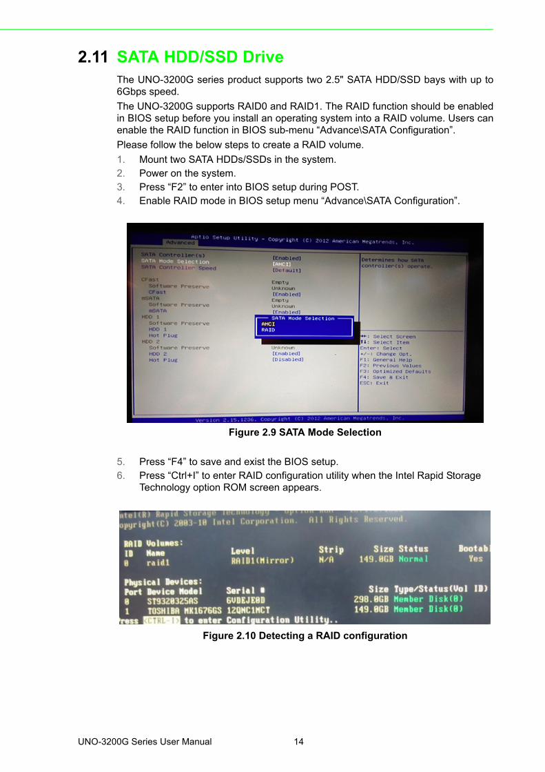
2.11 SATA HDD/SSD DriveThe UNO-3200G series product supports two 2.5" SATA HDD/SSD bays with up to6Gbps speed.
The UNO-3200G supports RAID0 and RAID1. The RAID function should be enabledin BIOS setup before you install an operating system into a RAID volume. Users canenable the RAID function in BIOS sub-menu “Advance\SATA Configuration”.
Please follow the below steps to create a RAID volume.
1. Mount two SATA HDDs/SSDs in the system.2. Power on the system.3. Press “F2” to enter into BIOS setup during POST.4. Enable RAID mode in BIOS setup menu “Advance\SATA Configuration”.
Figure 2.9 SATA Mode Selection
5. Press “F4” to save and exist the BIOS setup.6. Press “Ctrl+I” to enter RAID configuration utility when the Intel Rapid Storage
Technology option ROM screen appears.
Figure 2.10 Detecting a RAID configuration
UNO-3200G Series User Manual 14
Chapter 2
Hardw
areF
unctionality
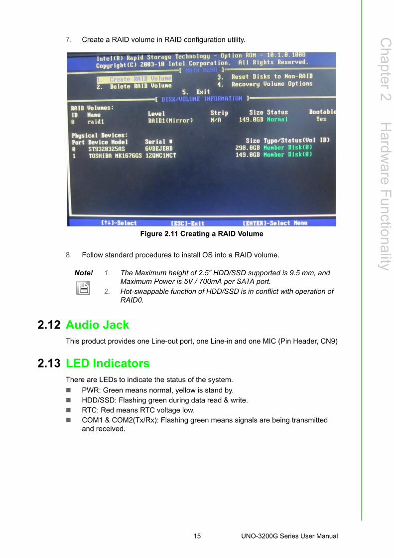
7. Create a RAID volume in RAID configuration utility.
Figure 2.11 Creating a RAID Volume
8. Follow standard procedures to install OS into a RAID volume.
2.12 Audio JackThis product provides one Line-out port, one Line-in and one MIC (Pin Header, CN9)
2.13 LED IndicatorsThere are LEDs to indicate the status of the system.
PWR: Green means normal, yellow is stand by. HDD/SSD: Flashing green during data read & write. RTC: Red means RTC voltage low. COM1 & COM2(Tx/Rx): Flashing green means signals are being transmitted
and received.
Note! 1. The Maximum height of 2.5" HDD/SSD supported is 9.5 mm, and Maximum Power is 5V / 700mA per SATA port.
2. Hot-swappable function of HDD/SSD is in conflict with operation of RAID0.
15 UNO-3200G Series User Manual

UNO-3200G Series User Manual 16
Chapter 3
3 Initial SetupThis chapter introduces how toinitialize UNO-3200G series.
Sections include:
Chassis Grounding
Connecting Power
Connecting a Hard Disk
BIOS Setup and System Assign-ments
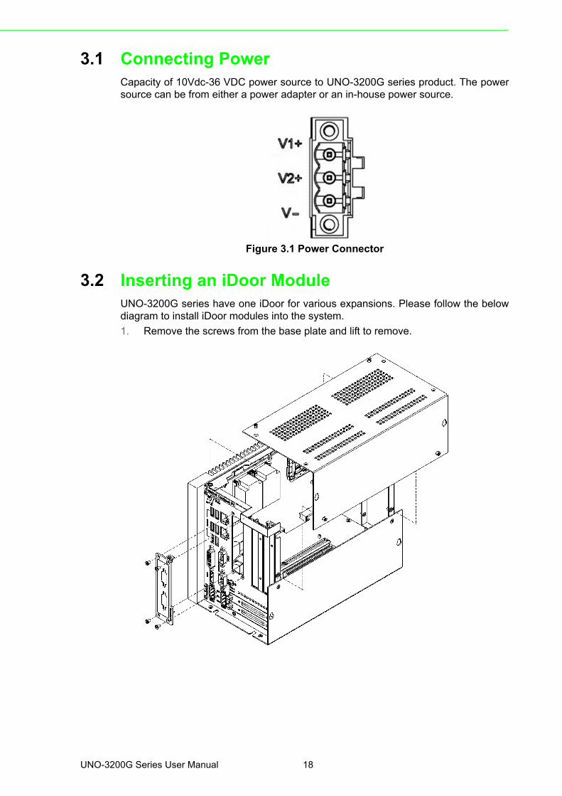
3.1 Connecting PowerCapacity of 10Vdc-36 VDC power source to UNO-3200G series product. The powersource can be from either a power adapter or an in-house power source.
Figure 3.1 Power Connector
3.2 Inserting an iDoor ModuleUNO-3200G series have one iDoor for various expansions. Please follow the belowdiagram to install iDoor modules into the system.
1. Remove the screws from the base plate and lift to remove.
UNO-3200G Series User Manual 18
Chapter 3
Initial Setup
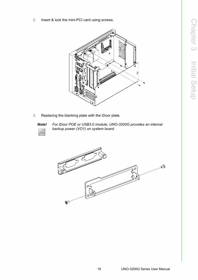
2. Insert & lock the mini-PCI card using screws.
3. Replacing the blanking plate with the iDoor plate.
Note! For iDoor POE or USB3.0 module, UNO-3200G provides an internal backup power (VO1) on system board.
19 UNO-3200G Series User Manual
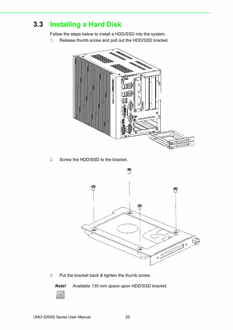
3.3 Installing a Hard DiskFollow the steps below to install a HDD/SSD into the system.
1. Release thumb screw and pull out the HDD/SSD bracket.
2. Screw the HDD/SSD to the bracket.
3. Put the bracket back & tighten the thumb screw.
Note! Available 130 mm space upon HDD/SSD bracket.
UNO-3200G Series User Manual 20
Chapter 3
Initial Setup
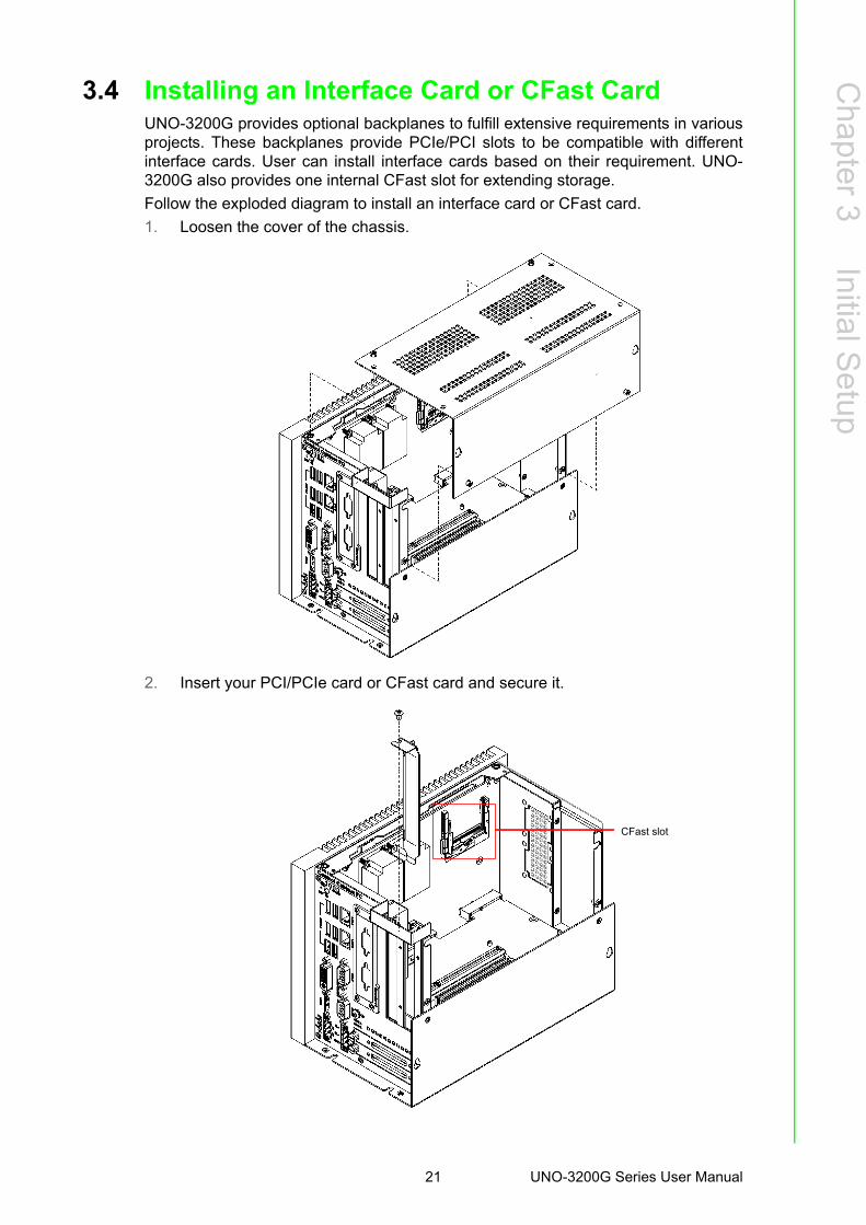
3.4 Installing an Interface Card or CFast CardUNO-3200G provides optional backplanes to fulfill extensive requirements in variousprojects. These backplanes provide PCIe/PCI slots to be compatible with differentinterface cards. User can install interface cards based on their requirement. UNO-3200G also provides one internal CFast slot for extending storage.
Follow the exploded diagram to install an interface card or CFast card.
1. Loosen the cover of the chassis.
2. Insert your PCI/PCIe card or CFast card and secure it.
CFast slot
21 UNO-3200G Series User Manual
3. Assemble the cover of the chassis.
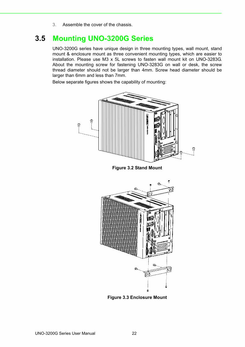
3.5 Mounting UNO-3200G SeriesUNO-3200G series have unique design in three mounting types, wall mount, standmount & enclosure mount as three convenient mounting types, which are easier toinstallation. Please use M3 x 5L screws to fasten wall mount kit on UNO-3283G.About the mounting screw for fastening UNO-3283G on wall or desk, the screwthread diameter should not be larger than 4mm. Screw head diameter should belarger than 6mm and less than 7mm.
Below separate figures shows the capability of mounting:
Figure 3.2 Stand Mount
Figure 3.3 Enclosure Mount
UNO-3200G Series User Manual 22
Chapter 3
Initial Setup
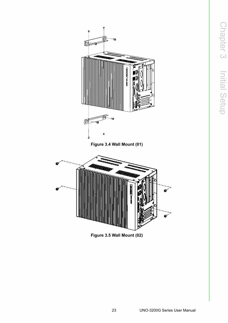
Figure 3.4 Wall Mount (01)
Figure 3.5 Wall Mount (02)
23 UNO-3200G Series User Manual

UNO-3200G Series User Manual 24
Appendix A
A System Settings and Pin Assignments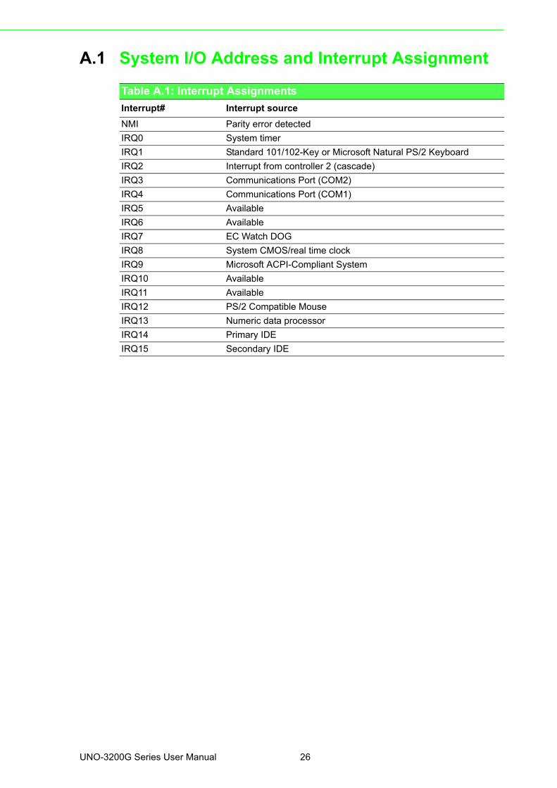
A.1 System I/O Address and Interrupt Assignment
Table A.1: Interrupt Assignments
Interrupt# Interrupt source
NMI Parity error detected
IRQ0 System timer
IRQ1 Standard 101/102-Key or Microsoft Natural PS/2 Keyboard
IRQ2 Interrupt from controller 2 (cascade)
IRQ3 Communications Port (COM2)
IRQ4 Communications Port (COM1)
IRQ5 Available
IRQ6 Available
IRQ7 EC Watch DOG
IRQ8 System CMOS/real time clock
IRQ9 Microsoft ACPI-Compliant System
IRQ10 Available
IRQ11 Available
IRQ12 PS/2 Compatible Mouse
IRQ13 Numeric data processor
IRQ14 Primary IDE
IRQ15 Secondary IDE
UNO-3200G Series User Manual 26
Appendix A
System
Settings
andP
inA
ssignments
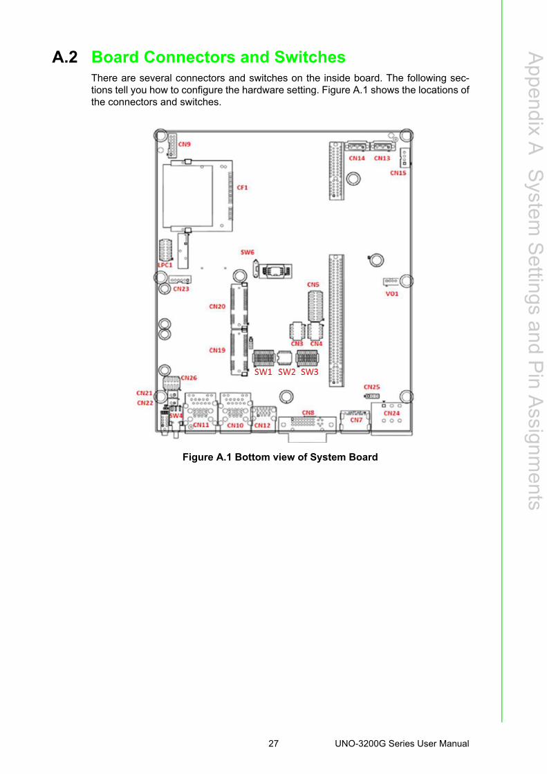
A.2 Board Connectors and Switches There are several connectors and switches on the inside board. The following sec-tions tell you how to configure the hardware setting. Figure A.1 shows the locations ofthe connectors and switches.
Figure A.1 Bottom view of System Board
27 UNO-3200G Series User Manual
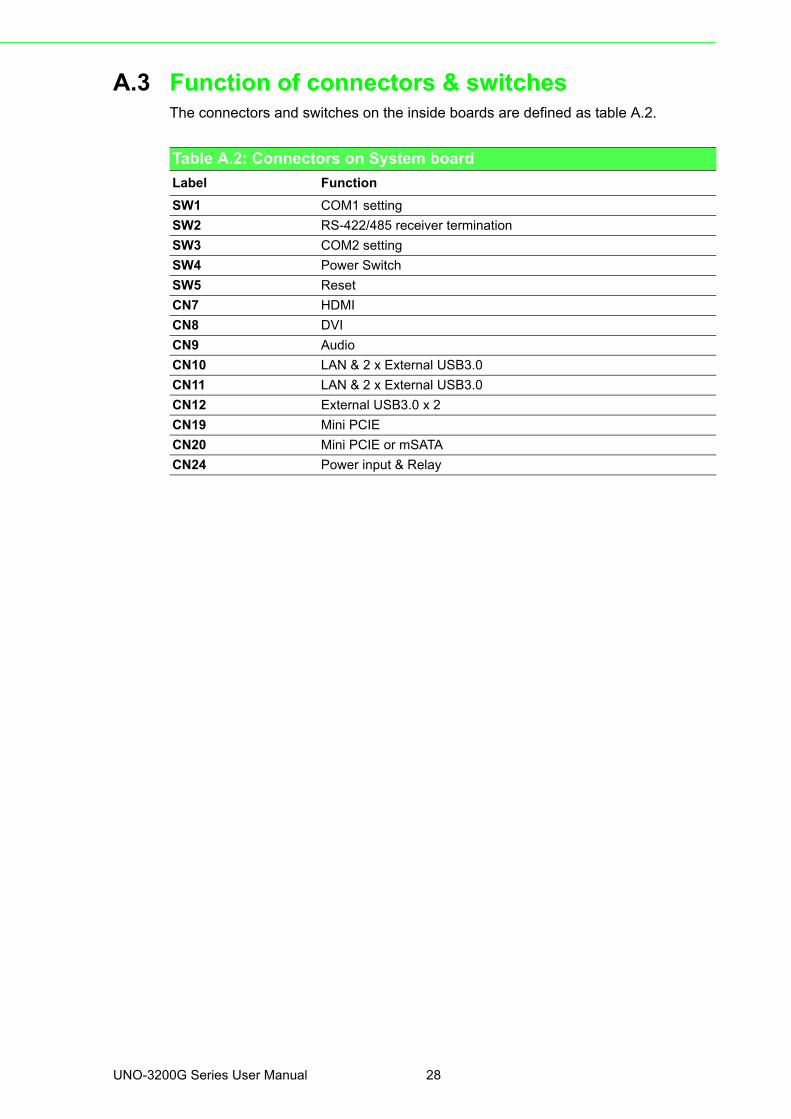
A.3 Function of connectors & switchesThe connectors and switches on the inside boards are defined as table A.2.
Table A.2: Connectors on System board
Label Function
SW1 COM1 setting
SW2 RS-422/485 receiver termination
SW3 COM2 setting
SW4 Power Switch
SW5 Reset
CN7 HDMI
CN8 DVI
CN9 Audio
CN10 LAN & 2 x External USB3.0
CN11 LAN & 2 x External USB3.0
CN12 External USB3.0 x 2
CN19 Mini PCIE
CN20 Mini PCIE or mSATA
CN24 Power input & Relay
UNO-3200G Series User Manual 28
Appendix A
System
Settings
andP
inA
ssignments
A.4 Audio (Pin header)
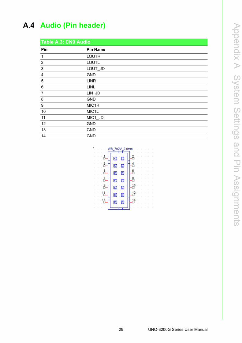
Table A.3: CN9 Audio
Pin Pin Name
1 LOUTR
2 LOUTL
3 LOUT_JD
4 GND
5 LINR
6 LINL
7 LIN_JD
8 GND
9 MIC1R
10 MIC1L
11 MIC1_JD
12 GND
13 GND
14 GND
29 UNO-3200G Series User Manual
A.5 COM1/COM2
A.6 COM3/COM4
Table A.4: COM POER Pin Definition
Connector Function
Pin RS232 RS422 RS485
1 DCD 422_TXD- 485_Data-
2 RXD 422_TXD+ 485_Data+
3 TXD 422_RXD+
4 DTR 422_RXD-
5 GND GND
6 DSR
7 RTS
8 CTS
9 RIC
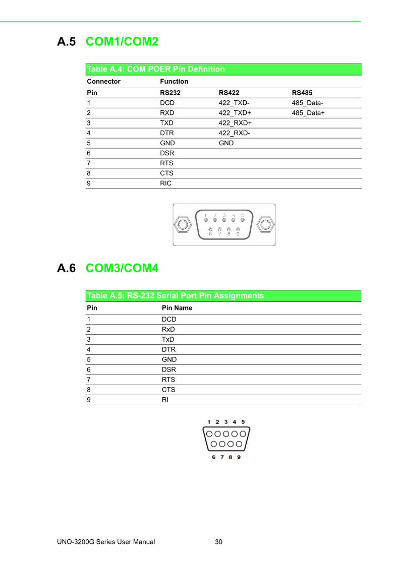
Table A.5: RS-232 Serial Port Pin Assignments
Pin Pin Name
1 DCD
2 RxD
3 TxD
4 DTR
5 GND
6 DSR
7 RTS
8 CTS
9 RI
UNO-3200G Series User Manual 30
Appendix A
System
Settings
andP
inA
ssignments
A.7 Power Connector (PWR)
A.8 Relay Connector (PWR)
Table A.6: Power connector pin assignments1 V1+
2 V2+
3 V-
Table A.7: Relay Connector (PWR)RL + Relay Normal Open
RL - Relay COM
GND Case Ground
31 UNO-3200G Series User Manual
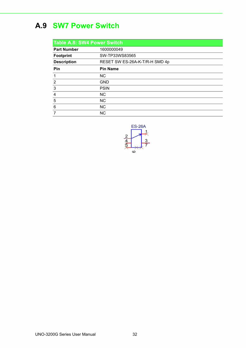
A.9 SW7 Power Switch
Table A.8: SW4 Power Switch Part Number 1600000049
Footprint SW-TP33WS83565
Description RESET SW ES-26A-K-T/R-H SMD 4p
Pin Pin Name
1 NC
2 GND
3 PSIN
4 NC
5 NC
6 NC
7 NC
UNO-3200G Series User Manual 32
Appendix A
System
Settings
andP
inA
ssignments
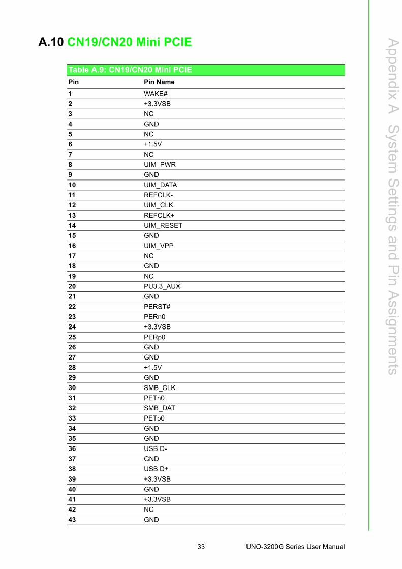
A.10 CN19/CN20 Mini PCIE
Table A.9: CN19/CN20 Mini PCIE
Pin Pin Name
1 WAKE#
2 +3.3VSB
3 NC
4 GND
5 NC
6 +1.5V
7 NC
8 UIM_PWR
9 GND
10 UIM_DATA
11 REFCLK-
12 UIM_CLK
13 REFCLK+
14 UIM_RESET
15 GND
16 UIM_VPP
17 NC
18 GND
19 NC
20 PU3.3_AUX
21 GND
22 PERST#
23 PERn0
24 +3.3VSB
25 PERp0
26 GND
27 GND
28 +1.5V
29 GND
30 SMB_CLK
31 PETn0
32 SMB_DAT
33 PETp0
34 GND
35 GND
36 USB D-
37 GND
38 USB D+
39 +3.3VSB
40 GND
41 +3.3VSB
42 NC
43 GND
33 UNO-3200G Series User Manual
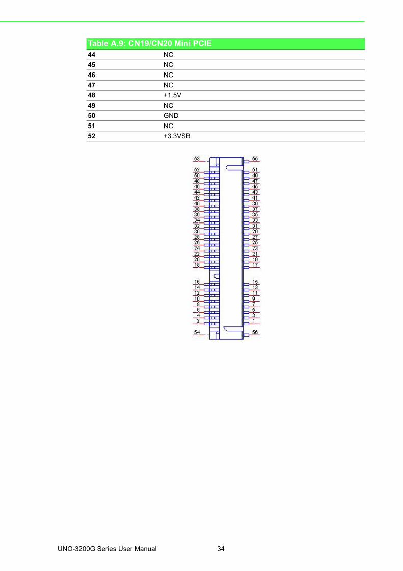
44 NC
45 NC
46 NC
47 NC
48 +1.5V
49 NC
50 GND
51 NC
52 +3.3VSB
Table A.9: CN19/CN20 Mini PCIE
UNO-3200G Series User Manual 34
Appendix A
System
Settings
andP
inA
ssignments
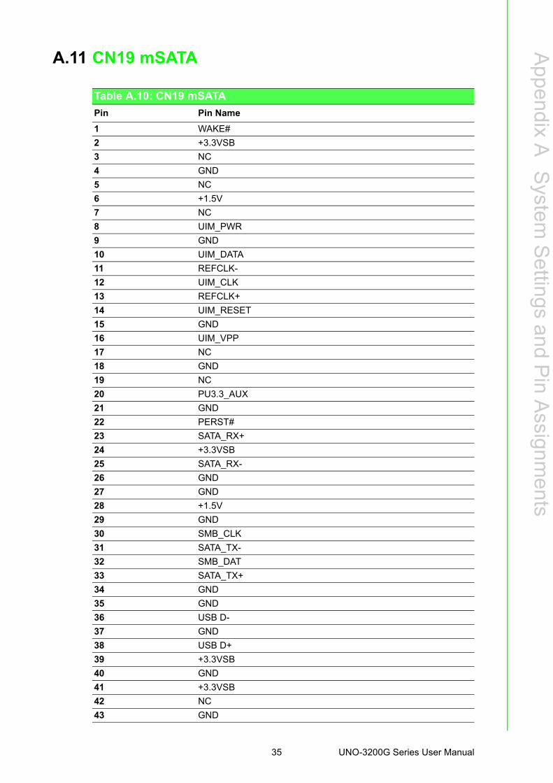
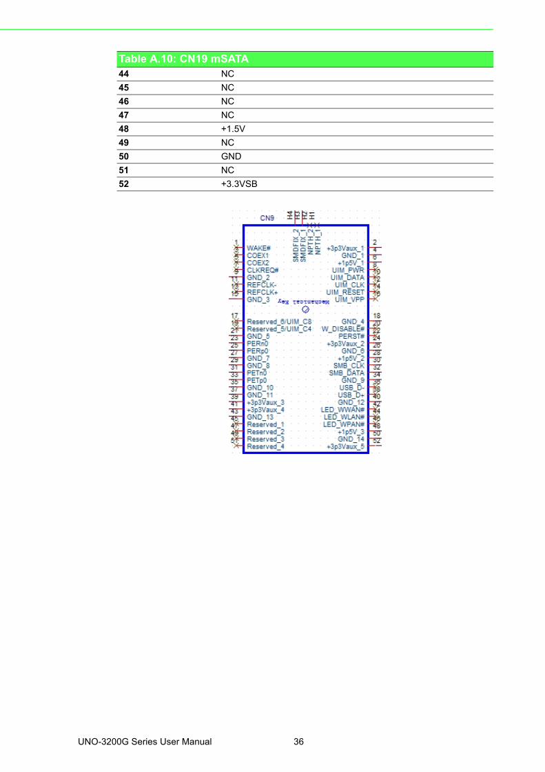
A.11 CN19 mSATA
Table A.10: CN19 mSATA
Pin Pin Name
1 WAKE#
2 +3.3VSB
3 NC
4 GND
5 NC
6 +1.5V
7 NC
8 UIM_PWR
9 GND
10 UIM_DATA
11 REFCLK-
12 UIM_CLK
13 REFCLK+
14 UIM_RESET
15 GND
16 UIM_VPP
17 NC
18 GND
19 NC
20 PU3.3_AUX
21 GND
22 PERST#
23 SATA_RX+
24 +3.3VSB
25 SATA_RX-
26 GND
27 GND
28 +1.5V
29 GND
30 SMB_CLK
31 SATA_TX-
32 SMB_DAT
33 SATA_TX+
34 GND
35 GND
36 USB D-
37 GND
38 USB D+
39 +3.3VSB
40 GND
41 +3.3VSB
42 NC
43 GND
35 UNO-3200G Series User Manual
44 NC
45 NC
46 NC
47 NC
48 +1.5V
49 NC
50 GND
51 NC
52 +3.3VSB
Table A.10: CN19 mSATA
UNO-3200G Series User Manual 36
Appendix A
System
Settings
andP
inA
ssignments
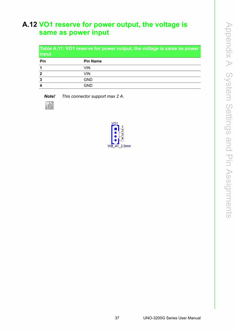
A.12 VO1 reserve for power output, the voltage is same as power input
Table A.11: VO1 reserve for power output, the voltage is same as power input
Pin Pin Name
1 VIN
2 VIN
3 GND
4 GND
Note! This connector support max 2 A.
37 UNO-3200G Series User Manual
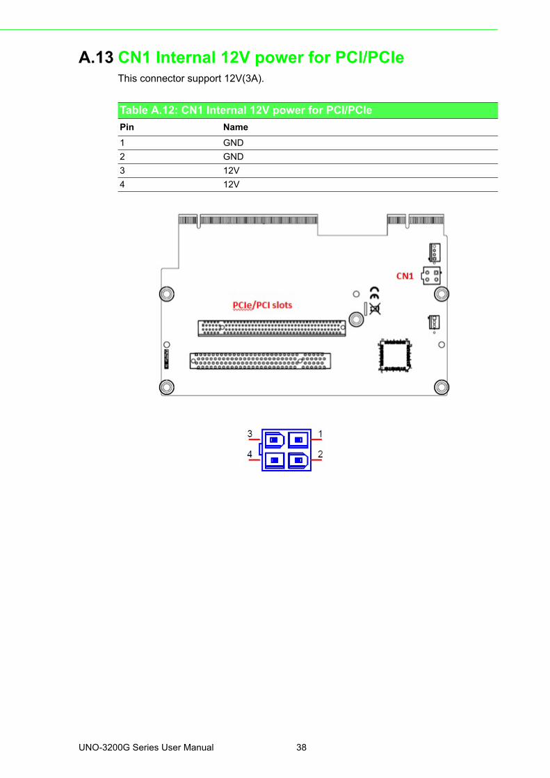
A.13 CN1 Internal 12V power for PCI/PCIe This connector support 12V(3A).
Table A.12: CN1 Internal 12V power for PCI/PCIe
Pin Name
1 GND
2 GND
3 12V
4 12V
UNO-3200G Series User Manual 38
Appendix A
System
Settings
andP
inA
ssignments
39 UNO-3200G Series User Manual

www.advantech.comPlease verify specifications before quoting. This guide is intended for referencepurposes only.All product specifications are subject to change without notice.No part of this publication may be reproduced in any form or by any means,electronic, photocopying, recording or otherwise, without prior written permis-sion of the publisher.All brand and product names are trademarks or registered trademarks of theirrespective companies.© Advantech Co., Ltd. 2017
![Everio Controller - JVCzip」並儲存在電腦桌面上。 4 用滑鼠右鍵按一下「EverioController.zip」並選擇 [解壓 縮全部] 以解壓縮檔案。 安裝 1 啟動電腦上的](https://static.fdocuments.us/doc/165x107/5f1058117e708231d448a4ea/everio-controller-jvc-zipoeeeoee-4-ceeoeoeeveriocontrollerzipe.jpg)