USER MANUAL - · PDF fileUSER MANUAL LONGO Programmable Controller ... iv. LONGO Programmable...
57
USER MANUAL LONGO Programmable Controller LPC Manager Version 4 SMARTEH d.o.o. / Poljubinj 114 / 5220 Tolmin / Slovenia / Tel.: +386 (0)5 388 44 00 / e-mail: [email protected] / www.smarteh.si
Transcript of USER MANUAL - · PDF fileUSER MANUAL LONGO Programmable Controller ... iv. LONGO Programmable...
USER MANUAL
LONGO Programmable ControllerLPC Manager
Version 4
SMARTEH d.o.o. / Poljubinj 114 / 5220 Tolmin / Slovenia / Tel.: +386 (0)5 388 44 00 / e-mail: [email protected] / www.smarteh.si
LONGO Programmable Controller LPC Manager
Written by SMARTEH d.o.o.Copyright © 2010-2016, SMARTEH d.o.o.
User manualDocument Version: 4January, 2016
i
LONGO Programmable Controller LPC Manager
LONGO Programmable Controller LPC Manager
1 ABOUT THIS DOCUMENT......................................................................1
1.1 Who Should Read This Document....................................................11.2 Terminology.............................................................................2
1.2.1 LPC Family products based terminology.................................21.2.2 LPC Manager based terminology..........................................31.2.3 Conventions used in this document......................................3
2 LPC MANAGER SOFTWARE....................................................................4
2.1 Introduction.............................................................................42.2 LPC Manager editor....................................................................52.3 Main menu..............................................................................5
2.3.1 File.............................................................................52.3.2 Edit............................................................................62.3.3 Display.........................................................................62.3.4 Help............................................................................6
2.4 Toolbars.................................................................................72.5 Project window.......................................................................10
2.5.1 Topology.....................................................................10Build - Transfer procedure......................................................102.5.2 Project (program structure window)...................................11Add new (DataTypes, Functions, Function Blocks, Programs andResources)..........................................................................11Right-click menu (Project name)...............................................11Right-click menu (DataTypes, Functions, Function Blocks, Programs andResources)..........................................................................11Right-click menu (Function, Function block and Program).................12Double-click (Project name, DataTypes, Functions, Function Blocks,Programs and Resources)........................................................122.5.3 Project (instances window)..............................................132.5.4 Editor workspace...........................................................13
2.6 Library..................................................................................14BLOCK PROPERTIES...............................................................142.6.1 Standard function blocks.................................................15SR....................................................................................15RS....................................................................................15SEMA.................................................................................16R TRIG...............................................................................16
ii
LONGO Programmable Controller LPC Manager
F TRIG...............................................................................16CTU CTU_DINT, CTU_LINT, CTU_UDINT, CTU_ULINT............17CTD CTD_DINT, CTD_LINT, CTD_UDINT, CTD_ULINT............17CTUD CTUD_DINT, CTUD_LINT, CTUD_UDINT, CTUD_ULINT....18TP....................................................................................19TON..................................................................................20TOF..................................................................................202.6.2 Additional function block.................................................21RTC..................................................................................21INTEGRAL...........................................................................21DERIVATIVE.........................................................................21PID...................................................................................22RAMP................................................................................22HYSTERESIS.........................................................................222.6.3 Type conversion............................................................23TYPE[A]_TO_TYPE[B].............................................................232.6.4 Numerical...................................................................24ABS..................................................................................24SQRT.................................................................................24LN....................................................................................24LOG..................................................................................24EXP..................................................................................24SIN...................................................................................24COS..................................................................................25TAN..................................................................................25ASIN.................................................................................25ACOS................................................................................25ATAN................................................................................252.6.5 Arithmetic...................................................................26ADD..................................................................................26MUL..................................................................................26SUB..................................................................................26DIV...................................................................................26MOD.................................................................................27EXPT.................................................................................27MOVE................................................................................272.6.6 Time..........................................................................28ADD..................................................................................28ADD_TIME...........................................................................28ADD..................................................................................28ADD_TOD_TIME....................................................................28ADD..................................................................................29ADD_DT_TIME......................................................................29MUL..................................................................................29
iii
LONGO Programmable Controller LPC Manager
MULTIME............................................................................29SUB_TIME...........................................................................29SUB..................................................................................29SUB..................................................................................29SUB_DATE_DATE...................................................................30SUB..................................................................................30SUB_TOD_TIME.....................................................................30SUB..................................................................................30SUB_TOD_TOD.....................................................................30SUB..................................................................................30SUB_DT_TIME......................................................................30SUB..................................................................................31SUB_DT_TIME......................................................................31DIV...................................................................................31DIVTIME.............................................................................312.6.7 Bit-shift......................................................................32SHL..................................................................................32SHR..................................................................................32ROR..................................................................................32ROL..................................................................................322.6.8 Bitwise.......................................................................33AND..................................................................................33OR...................................................................................33XOR..................................................................................33NOT..................................................................................332.6.9 Selection....................................................................34SEL...................................................................................34MAX..................................................................................34MIN..................................................................................34LIMIT................................................................................35MUX..................................................................................352.6.10 Comparison................................................................36GT...................................................................................36GE....................................................................................36EQ....................................................................................36LT....................................................................................37LE....................................................................................37NE....................................................................................372.6.11 Character string...........................................................38LEN..................................................................................38LEFT.................................................................................38RIGHT...............................................................................38MID...................................................................................38CONCAT.............................................................................39
iv
LONGO Programmable Controller LPC Manager
CONCAT_DAT_TOD................................................................39INSERT..............................................................................39DELETE..............................................................................39REPLACE............................................................................39FIND.................................................................................402.6.12 Native POUs...............................................................40LOGGER.............................................................................402.6.13 LPC POUs...................................................................41DEW_POINT.........................................................................41GET_RETAIN_DATA................................................................41SET_RETAIN_DATA................................................................41FIND_RETAIN_DATA...............................................................42PID_A................................................................................422.6.14 User-defined POUs........................................................43
2.7 Debugger...............................................................................432.8 Search..................................................................................442.9 Console.................................................................................442.10 PLC Log...............................................................................44
3 PROGRAMMING LANGUAGES................................................................45
3.1 IL - Instruction List...................................................................453.2 ST - Structured Text.................................................................463.3 FBD - Function Block Diagram......................................................483.4 LD - Ladder Diagram.................................................................493.5 SFC - Sequential Function Chart...................................................50
APPENDIX A – ERROR REPORTING............................................................51
APPENDIX B – DOCUMENT HISTORY..........................................................52
v
LONGO Programmable Controller LPC Manager
1 ABOUT THIS DOCUMENT
LPC Manager user manual describes how to use application LPC Manager.
1.1 Who Should Read This DocumentIf you are new to the LPC Manager software and want to get started with it or upgrading fromprevious versions then You should read this document.
In order to properly understand this document, it is necessary to understand at least basics of theLPC hardware. For this it is highly recommended to view LPC Getting Started video (installed withLPC Smarteh IDE setup) or to go through the proper training to a certified SMARTEH d.o.o. trainer.On this short course you will learn all the basics and have the opportunity to become a certifiedSMARTEH d.o.o. integrator. Not only you will get a head start, but you will also become a part of thegrowing group of LPC users, get a chance to ask direct questions to experts, get contacts with otherintegrators and companies all over the world...
NOTE: Since LPC Manager is based on IEC 61131-3 international standard, please refer to PLC(programming logic controllers) programming languages International Standard IEC 61131-3 for moredetailed information.
For more information, call +386 5 388 44 00 or e-mail to [email protected] and reserve your ticket forthe LPC certificate training:
1
LONGO Programmable Controller LPC Manager
1.2 TerminologyThroughout this manual, various phrases are used. Here is a description of some of them.
1.2.1 LPC Family products based terminology
LONGO™
... is a family of products (hardware and software) and is a trademark of SMARTEH d.o.o.
LPC™
... Longo Programming Controller and is a trademark of SMARTEH d.o.o.
IDE
… is a integrated development environment.
LPC-2 Programming Controller
... is a family of hardware modules (MCU module, I/O modules and other modules).
LPC Smarteh IDE, LPC Manager
... are members of LPC family software.
2
LONGO Programmable Controller LPC Manager
1.2.2 LPC Manager based terminology
Beremiz
… is a free software framework for automation (http://www.beremiz.org)
IEC 61131-3
… is an international standard for programmable controllers, programmable languages
PLC
… Programmable Logic Controller
MCU
… Main Control Unit
POU
… Program Organization Unit
Programming Languages
IL … Instruction List
ST … Structured Text
LD … Ladder Diagram
FBD … Function Block Diagram
SFC … Sequential Function Chart
True
… Logical 1, on, active, high state
False
… Logical 0, off, not active, low state
1.2.3 Conventions used in this document
Items appearing in this document are sometimes given a special appearance to set them apart fromthe regular text. Here's how they look:
ItalicUsed for marking important keywords.
NEW:Used to mark sections which changed most from previous versions.
3
LONGO Programmable Controller LPC Manager
2 LPC MANAGER SOFTWARE
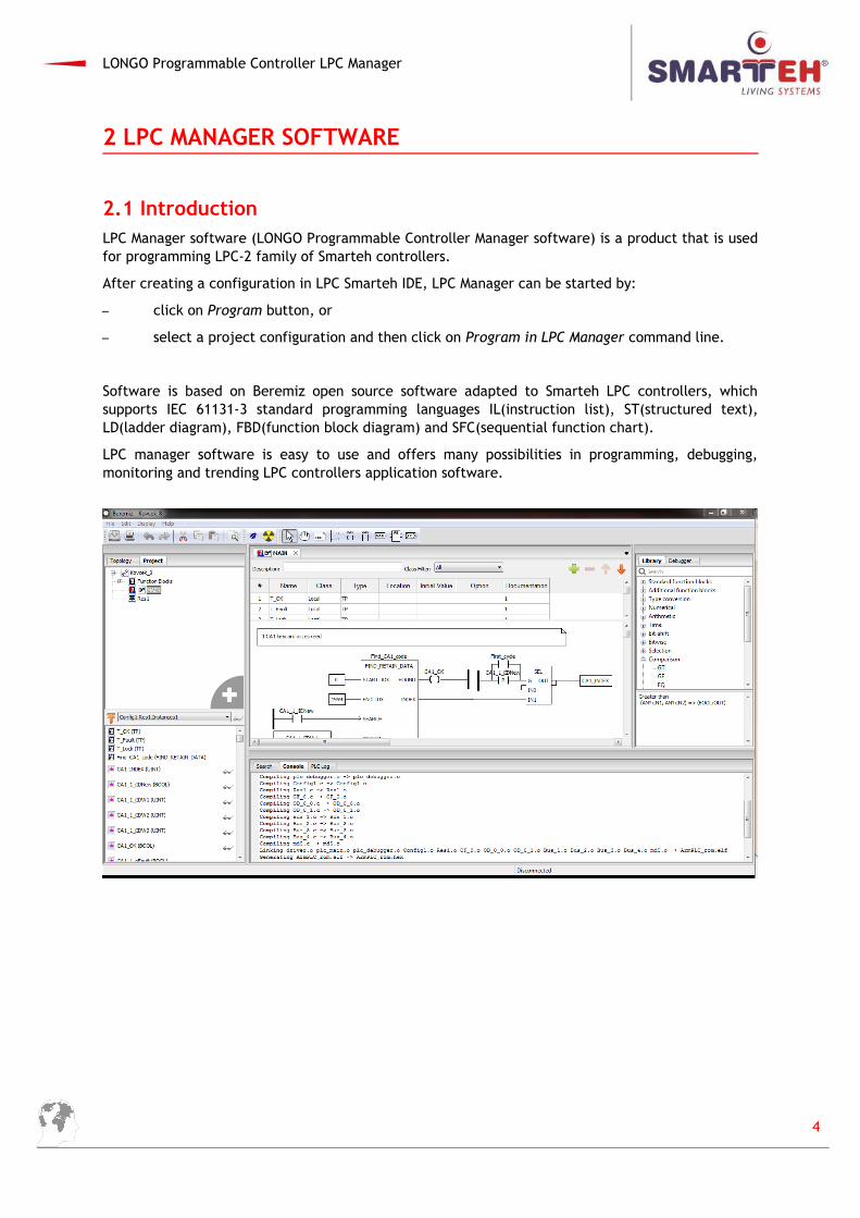
2.1 IntroductionLPC Manager software (LONGO Programmable Controller Manager software) is a product that is usedfor programming LPC-2 family of Smarteh controllers.
After creating a configuration in LPC Smarteh IDE, LPC Manager can be started by:
– click on Program button, or
– select a project configuration and then click on Program in LPC Manager command line.
Software is based on Beremiz open source software adapted to Smarteh LPC controllers, whichsupports IEC 61131-3 standard programming languages IL(instruction list), ST(structured text),LD(ladder diagram), FBD(function block diagram) and SFC(sequential function chart).
LPC manager software is easy to use and offers many possibilities in programming, debugging,monitoring and trending LPC controllers application software.
4
LONGO Programmable Controller LPC Manager
2.2 LPC Manager editorLPC Manager software consists of:
Main menu: File, Edit, Display, Help
Tool bars: Save, Print, Undo, Redo, Cut, Copy, Paste, Search in Project; Simulate, Debug; Select and object, Move the view, Create a new comment, Create a new variable,
Create a new block, Create a new connection
Topology and Project window
Variables and Editor workspace window
Search, Console and PLC Log window
Library and Debugging window
2.3 Main menuIn main menu you can find options
File, Edit, Display, and Help
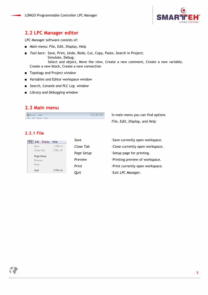
2.3.1 File
Save -Save currently open workspace.
Close Tab -Close currently open workspace.
Page Setup -Setup page for printing.
Preview -Printing preview of workspace.
Print -Print currently open workspace.
Quit -Exit LPC Manager.
5
LONGO Programmable Controller LPC Manager
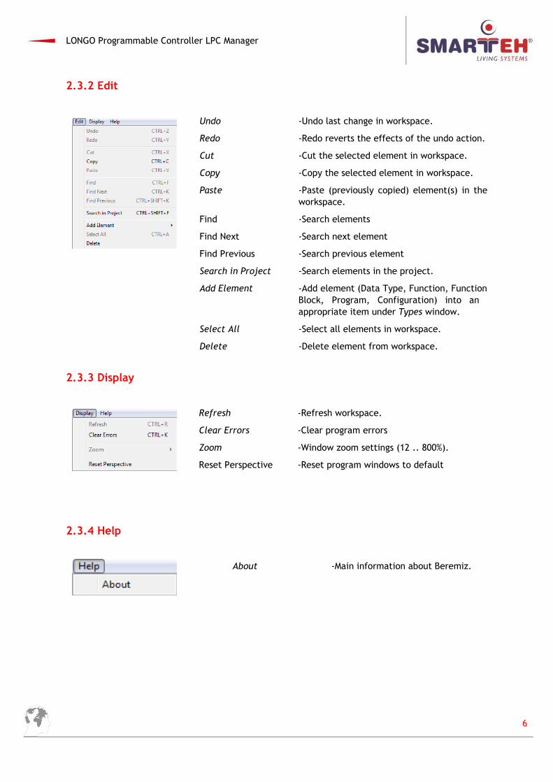
2.3.2 Edit
Undo -Undo last change in workspace.
Redo -Redo reverts the effects of the undo action.
Cut -Cut the selected element in workspace.
Copy -Copy the selected element in workspace.
Paste -Paste (previously copied) element(s) in theworkspace.
Find -Search elements
Find Next -Search next element
Find Previous -Search previous element
Search in Project -Search elements in the project.
Add Element -Add element (Data Type, Function, FunctionBlock, Program, Configuration) into an appropriate item under Types window.
Select All -Select all elements in workspace.
Delete -Delete element from workspace.
2.3.3 Display
Refresh -Refresh workspace.
Clear Errors -Clear program errors
Zoom -Window zoom settings (12 .. 800%).
Reset Perspective -Reset program windows to default
2.3.4 Help
About -Main information about Beremiz.
6
LONGO Programmable Controller LPC Manager
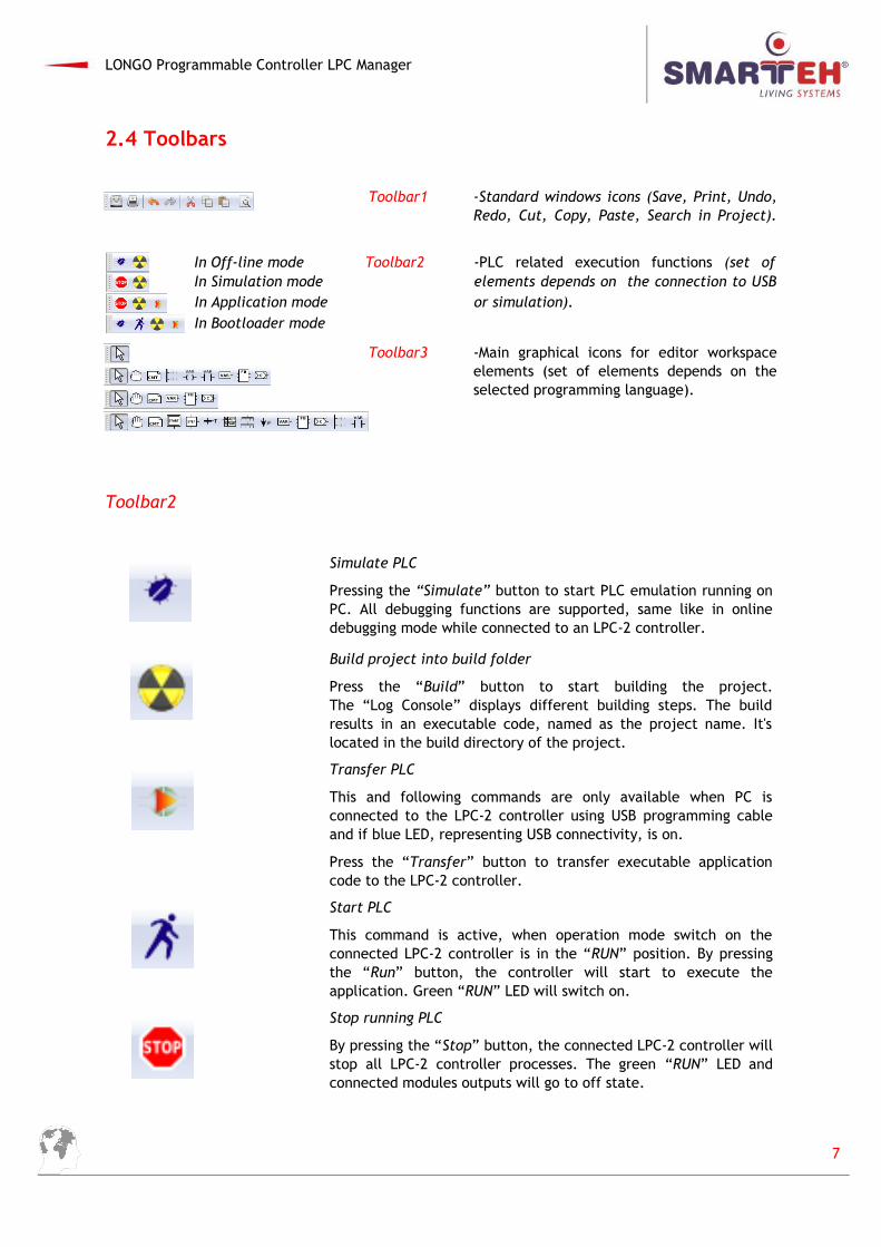
2.4 Toolbars
Toolbar1 -Standard windows icons (Save, Print, Undo,Redo, Cut, Copy, Paste, Search in Project).
In Off-line mode Toolbar2 -PLC related execution functions (set of In Simulation mode elements depends on the connection to USB
In Application mode or simulation). In Bootloader mode
Toolbar3 -Main graphical icons for editor workspaceelements (set of elements depends on theselected programming language).
Toolbar2
Simulate PLC
Pressing the “Simulate” button to start PLC emulation running onPC. All debugging functions are supported, same like in onlinedebugging mode while connected to an LPC-2 controller.
Build project into build folder
Press the “Build” button to start building the project.The “Log Console” displays different building steps. The buildresults in an executable code, named as the project name. It'slocated in the build directory of the project.
Transfer PLC
This and following commands are only available when PC isconnected to the LPC-2 controller using USB programming cableand if blue LED, representing USB connectivity, is on.
Press the “Transfer” button to transfer executable applicationcode to the LPC-2 controller.
Start PLC
This command is active, when operation mode switch on theconnected LPC-2 controller is in the “RUN” position. By pressingthe “Run” button, the controller will start to execute theapplication. Green “RUN” LED will switch on.
Stop running PLC
By pressing the “Stop” button, the connected LPC-2 controller willstop all LPC-2 controller processes. The green “RUN” LED andconnected modules outputs will go to off state.
7
LONGO Programmable Controller LPC Manager
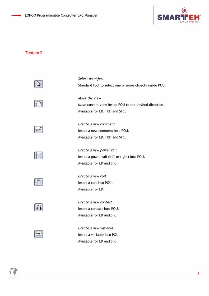
Toolbar3
Select an object
Standard tool to select one or more objects inside POU.
Move the view
Move current view inside POU to the desired direction.
Available for LD, FBD and SFC.
Create a new comment
Insert a new comment into POU.
Available for LD, FBD and SFC.
Create a new power rail
Insert a power rail (left or right) into POU.
Available for LD and SFC.
Create a new coil
Insert a coil into POU.
Available for LD.
Create a new contact
Insert a contact into POU.
Available for LD and SFC.
Create a new variable
Insert a variable into POU.
Available for LD and SFC.
8
LONGO Programmable Controller LPC Manager
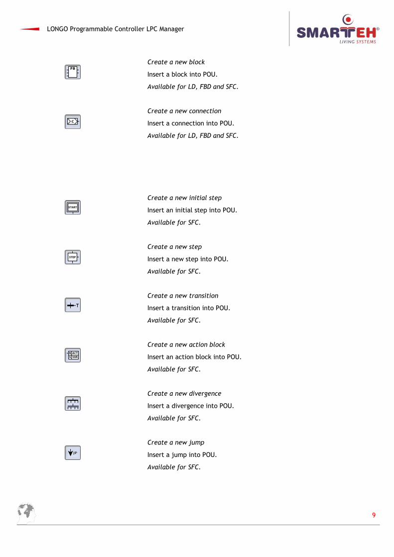
Create a new block
Insert a block into POU.
Available for LD, FBD and SFC.
Create a new connection
Insert a connection into POU.
Available for LD, FBD and SFC.
Create a new initial step
Insert an initial step into POU.
Available for SFC.
Create a new step
Insert a new step into POU.
Available for SFC.
Create a new transition
Insert a transition into POU.
Available for SFC.
Create a new action block
Insert an action block into POU.
Available for SFC.
Create a new divergence
Insert a divergence into POU.
Available for SFC.
Create a new jump
Insert a jump into POU.
Available for SFC.
9
LONGO Programmable Controller LPC Manager
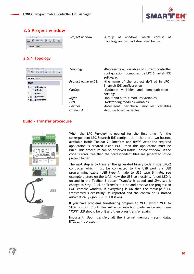
2.5 Project windowProject window -Group of windows which consist of
Topology and Project described below.
2.5.1 Topology
Topology -Represents all variables of current controllerconfiguration, composed by LPC Smarteh IDEsoftware.
Project name (MC8) -the name of the project defined in LPC Smarteh IDE configuration
CanOpen -CANopen variables and communication settings.
Right -Input and output modules variables.Left -Networking modules variables.Devices -Intelligent peripheral modules variablesOn Board -MCU on board variables.
Build - Transfer procedure
When the LPC Manager is opened for the first time (for thecorrespondent LPC Smarteh IDE configuration) there are two buttonsavailable inside Toolbar 2: Simulate and Build. After the requiredapplication is created inside POU, then this application must bebuilt. This procedure can be observed inside Console window. If thecode is error free then the correspondent files are generated insideproject folder.
The next step is to transfer the generated binary code inside LPC-2controller which must be connected to the USB port via USBprogramming cable (USB type A male to USB type B male, seeexample picture on the left). Now the USB connectivity (blue) LED ison and in the Toolbar 2 button Transfer is added and Simulate ischange to Stop. Click on Transfer button and observe the progress inLOG console window. If everything is OK then the message “PLCtransferred successfully” is reported and the controller is startedautomatically (green RUN LED is on).
If you have problems transferring program to MCU, switch MCU toSTOP position (Controller will enter into bootloader mode and green“RUN” LED should be off) and then press transfer again.
Important: Upon transfer, all the internal memory (retain data,RTC, ...) is erased.
10
LONGO Programmable Controller LPC Manager
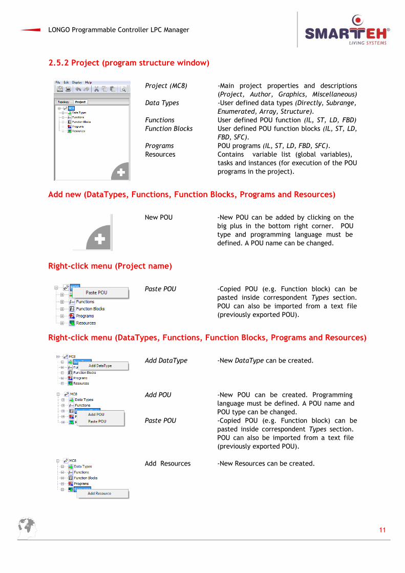
2.5.2 Project (program structure window)
Project (MC8) -Main project properties and descriptions(Project, Author, Graphics, Miscellaneous)
Data Types -User defined data types (Directly, Subrange,Enumerated, Array, Structure).
Functions User defined POU function (IL, ST, LD, FBD)Function Blocks User defined POU function blocks (IL, ST, LD,
FBD, SFC).Programs POU programs (IL, ST, LD, FBD, SFC).Resources Contains variable list (global variables),
tasks and instances (for execution of the POUprograms in the project).
Add new (DataTypes, Functions, Function Blocks, Programs and Resources)
New POU -New POU can be added by clicking on the big plus in the bottom right corner. POU type and programming language must be defined. A POU name can be changed.
Right-click menu (Project name)
Paste POU -Copied POU (e.g. Function block) can bepasted inside correspondent Types section.POU can also be imported from a text file(previously exported POU).
Right-click menu (DataTypes, Functions, Function Blocks, Programs and Resources)
Add DataType -New DataType can be created.
Add POU -New POU can be created. Programming language must be defined. A POU name and POU type can be changed.
Paste POU -Copied POU (e.g. Function block) can bepasted inside correspondent Types section. POU can also be imported from a text file (previously exported POU).
Add Resources -New Resources can be created.
11
LONGO Programmable Controller LPC Manager
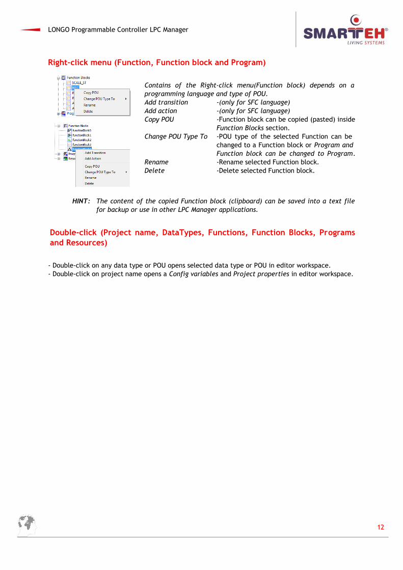
Right-click menu (Function, Function block and Program)
Contains of the Right-click menu(Function block) depends on aprogramming language and type of POU. Add transition -(only for SFC language)Add action -(only for SFC language)Copy POU -Function block can be copied (pasted) inside
Function Blocks section. Change POU Type To -POU type of the selected Function can be
changed to a Function block or Program and Function block can be changed to Program.
Rename -Rename selected Function block.Delete -Delete selected Function block.
HINT: The content of the copied Function block (clipboard) can be saved into a text filefor backup or use in other LPC Manager applications.
Double-click (Project name, DataTypes, Functions, Function Blocks, Programsand Resources)
- Double-click on any data type or POU opens selected data type or POU in editor workspace. - Double-click on project name opens a Config variables and Project properties in editor workspace.
12
LONGO Programmable Controller LPC Manager
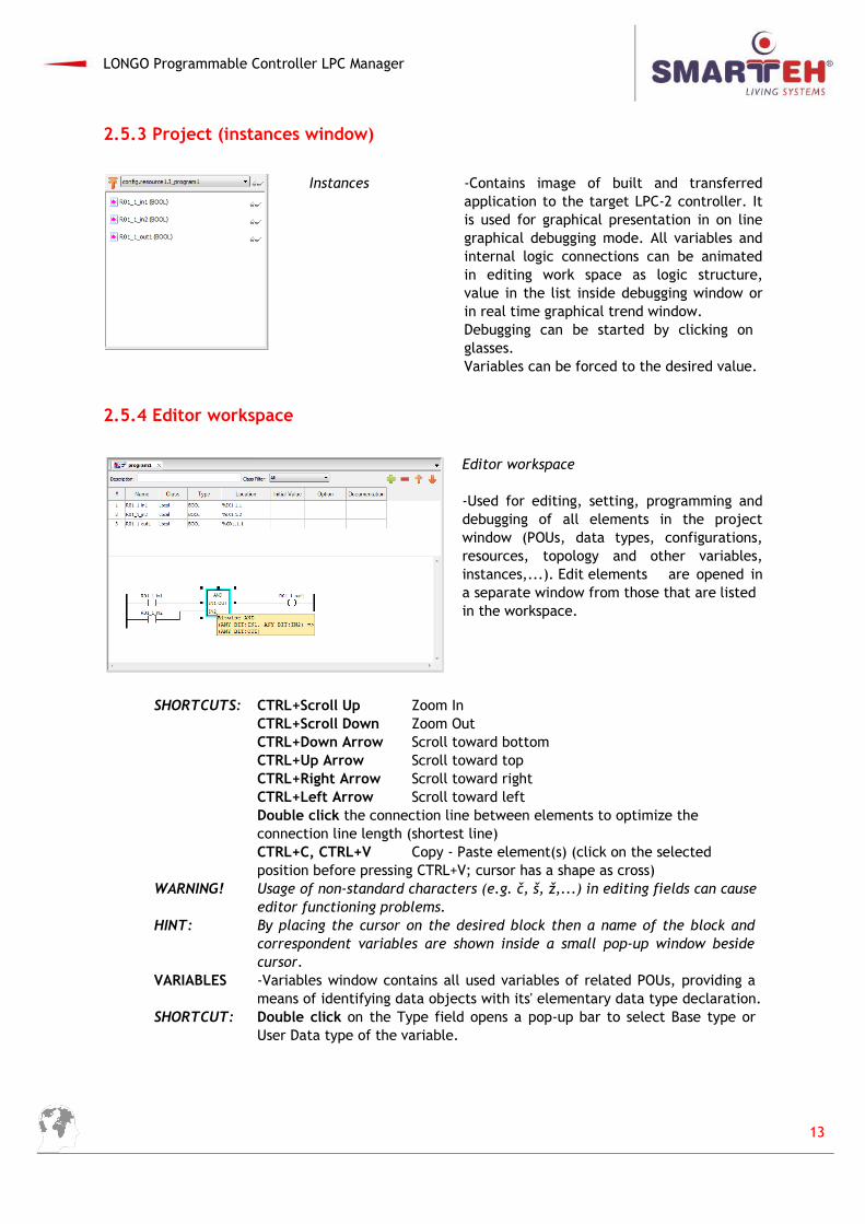
2.5.3 Project (instances window)
Instances -Contains image of built and transferredapplication to the target LPC-2 controller. Itis used for graphical presentation in on linegraphical debugging mode. All variables andinternal logic connections can be animatedin editing work space as logic structure,value in the list inside debugging window orin real time graphical trend window. Debugging can be started by clicking on glasses.Variables can be forced to the desired value.
2.5.4 Editor workspace
Editor workspace
-Used for editing, setting, programming anddebugging of all elements in the projectwindow (POUs, data types, configurations,resources, topology and other variables,instances,...). Edit elements are opened ina separate window from those that are listedin the workspace.
SHORTCUTS: CTRL+Scroll Up Zoom InCTRL+Scroll Down Zoom OutCTRL+Down Arrow Scroll toward bottomCTRL+Up Arrow Scroll toward topCTRL+Right Arrow Scroll toward rightCTRL+Left Arrow Scroll toward leftDouble click the connection line between elements to optimize theconnection line length (shortest line)CTRL+C, CTRL+V Copy - Paste element(s) (click on the selected position before pressing CTRL+V; cursor has a shape as cross)
WARNING! Usage of non-standard characters (e.g. č, š, ž,...) in editing fields can cause editor functioning problems.
HINT: By placing the cursor on the desired block then a name of the block and correspondent variables are shown inside a small pop-up window beside cursor.
VARIABLES -Variables window contains all used variables of related POUs, providing a means of identifying data objects with its' elementary data type declaration.
SHORTCUT: Double click on the Type field opens a pop-up bar to select Base type or User Data type of the variable.
13
LONGO Programmable Controller LPC Manager
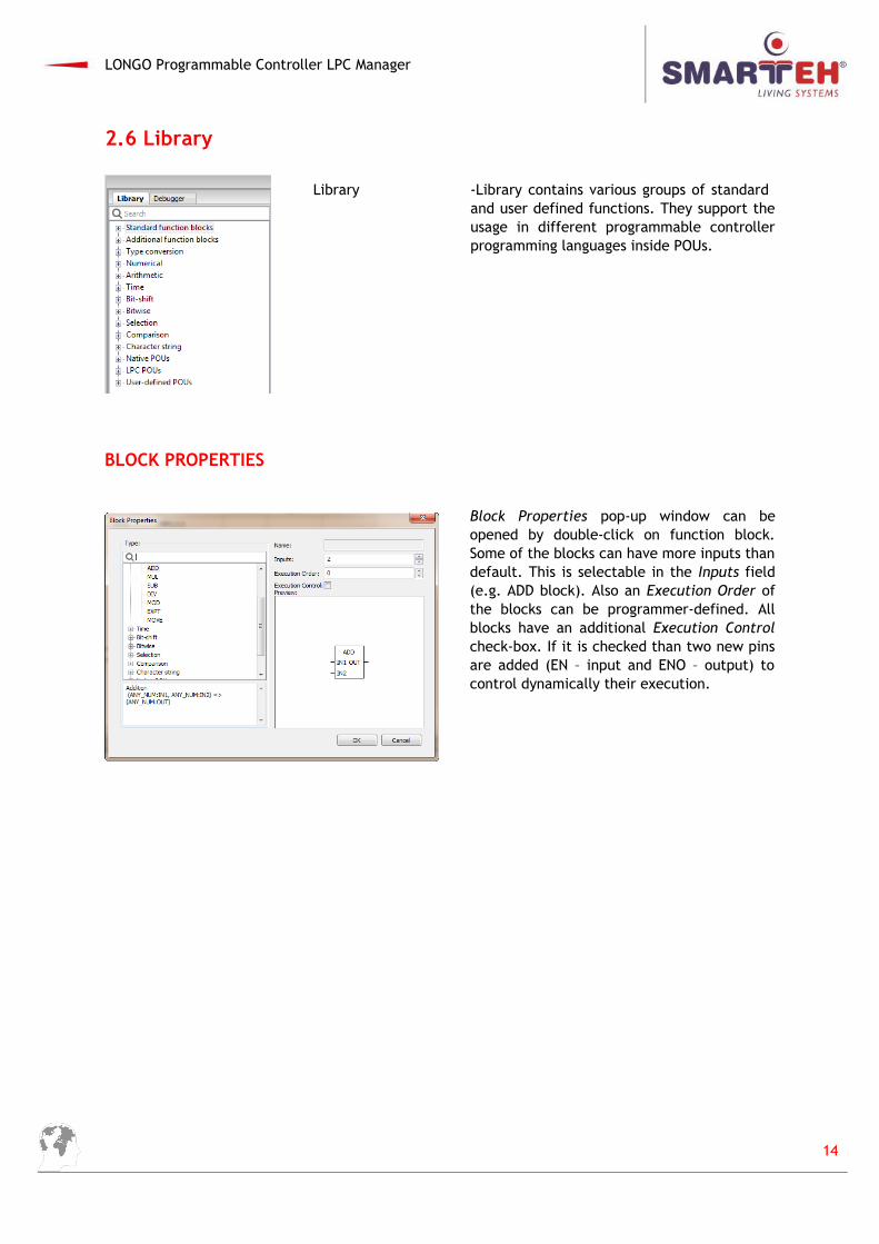
2.6 Library
Library -Library contains various groups of standard and user defined functions. They support theusage in different programmable controllerprogramming languages inside POUs.
BLOCK PROPERTIES
Block Properties pop-up window can beopened by double-click on function block.Some of the blocks can have more inputs thandefault. This is selectable in the Inputs field(e.g. ADD block). Also an Execution Order ofthe blocks can be programmer-defined. Allblocks have an additional Execution Controlcheck-box. If it is checked than two new pinsare added (EN – input and ENO – output) tocontrol dynamically their execution.
14
LONGO Programmable Controller LPC Manager
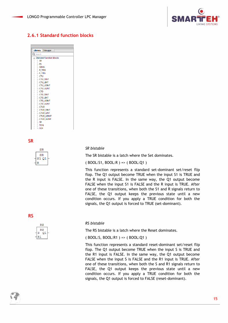
2.6.1 Standard function blocks
SR
SR bistable
The SR bistable is a latch where the Set dominates.
( BOOL:S1, BOOL:R ) => ( BOOL:Q1 )
This function represents a standard set-dominant set/reset flipflop. The Q1 output become TRUE when the input S1 is TRUE andthe R input is FALSE. In the same way, the Q1 output becomeFALSE when the input S1 is FALSE and the R input is TRUE. Afterone of these transitions, when both the S1 and R signals return toFALSE, the Q1 output keeps the previous state until a newcondition occurs. If you apply a TRUE condition for both thesignals, the Q1 output is forced to TRUE (set-dominant).
RS
RS bistable
The RS bistable is a latch where the Reset dominates.
( BOOL:S, BOOL:R1 ) => ( BOOL:Q1 )
This function represents a standard reset-dominant set/reset flipflop. The Q1 output become TRUE when the input S is TRUE andthe R1 input is FALSE. In the same way, the Q1 output becomeFALSE when the input S is FALSE and the R1 input is TRUE. Afterone of these transitions, when both the S and R1 signals return toFALSE, the Q1 output keeps the previous state until a newcondition occurs. If you apply a TRUE condition for both thesignals, the Q1 output is forced to FALSE (reset-dominant).
15
LONGO Programmable Controller LPC Manager
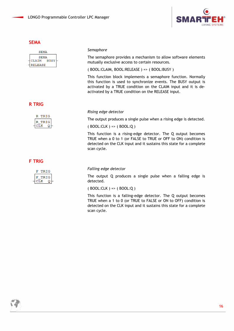
SEMA
Semaphore
The semaphore provides a mechanism to allow software elementsmutually exclusive access to certain resources.
( BOOL:CLAIM, BOOL:RELEASE ) => ( BOOL:BUSY )
This function block implements a semaphore function. Normallythis function is used to synchronize events. The BUSY output isactivated by a TRUE condition on the CLAIM input and it is de-activated by a TRUE condition on the RELEASE input.
R TRIG
Rising edge detector
The output produces a single pulse when a rising edge is detected.
( BOOL:CLK ) => ( BOOL:Q )
This function is a rising-edge detector. The Q output becomesTRUE when a 0 to 1 (or FALSE to TRUE or OFF to ON) condition isdetected on the CLK input and it sustains this state for a completescan cycle.
F TRIG
Falling edge detector
The output Q produces a single pulse when a falling edge isdetected.
( BOOL:CLK ) => ( BOOL:Q )
This function is a falling-edge detector. The Q output becomesTRUE when a 1 to 0 (or TRUE to FALSE or ON to OFF) condition isdetected on the CLK input and it sustains this state for a completescan cycle.
16
LONGO Programmable Controller LPC Manager
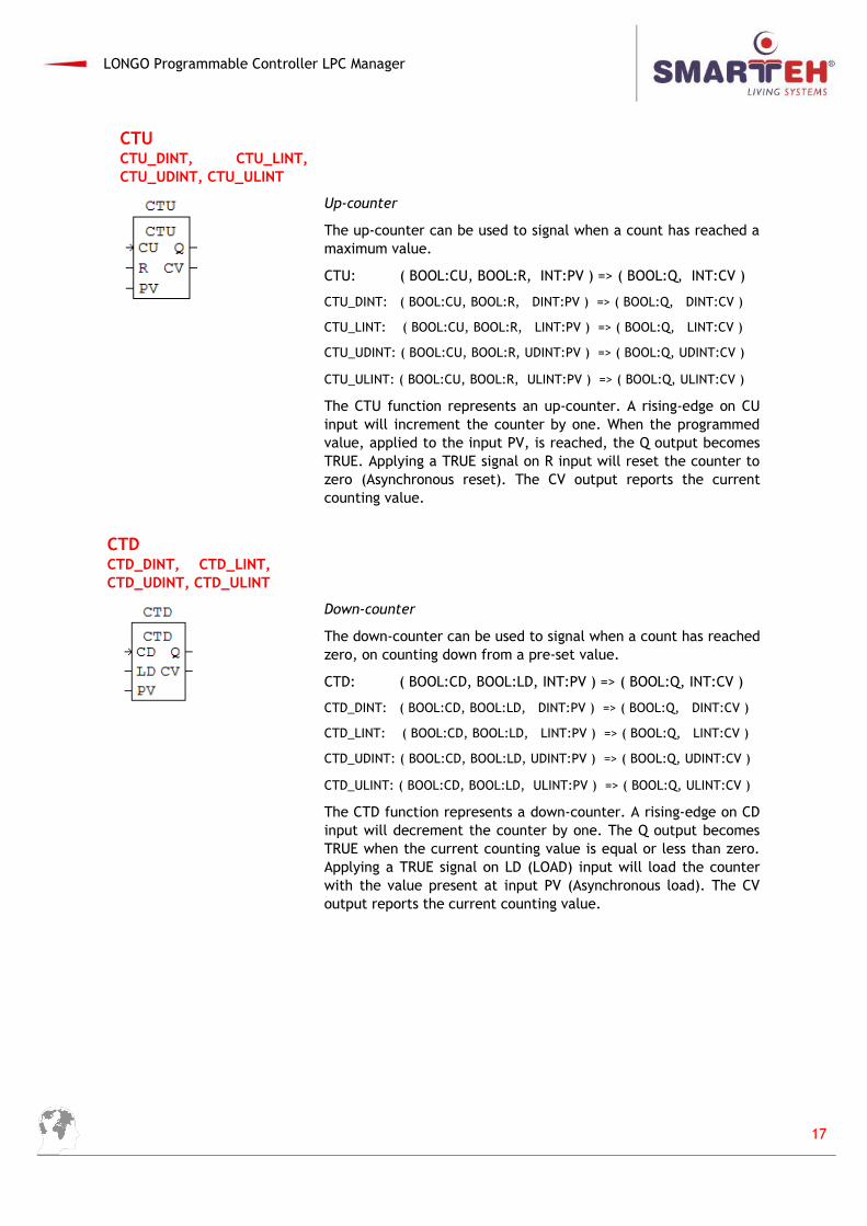
CTUCTU_DINT, CTU_LINT,CTU_UDINT, CTU_ULINT
Up-counter
The up-counter can be used to signal when a count has reached amaximum value.
CTU: ( BOOL:CU, BOOL:R, INT:PV ) => ( BOOL:Q, INT:CV )
CTU_DINT: ( BOOL:CU, BOOL:R, DINT:PV ) => ( BOOL:Q, DINT:CV )
CTU_LINT: ( BOOL:CU, BOOL:R, LINT:PV ) => ( BOOL:Q, LINT:CV )
CTU_UDINT: ( BOOL:CU, BOOL:R, UDINT:PV ) => ( BOOL:Q, UDINT:CV )
CTU_ULINT: ( BOOL:CU, BOOL:R, ULINT:PV ) => ( BOOL:Q, ULINT:CV )
The CTU function represents an up-counter. A rising-edge on CUinput will increment the counter by one. When the programmedvalue, applied to the input PV, is reached, the Q output becomesTRUE. Applying a TRUE signal on R input will reset the counter tozero (Asynchronous reset). The CV output reports the currentcounting value.
CTDCTD_DINT, CTD_LINT,CTD_UDINT, CTD_ULINT
Down-counter
The down-counter can be used to signal when a count has reachedzero, on counting down from a pre-set value.
CTD: ( BOOL:CD, BOOL:LD, INT:PV ) => ( BOOL:Q, INT:CV )
CTD_DINT: ( BOOL:CD, BOOL:LD, DINT:PV ) => ( BOOL:Q, DINT:CV )
CTD_LINT: ( BOOL:CD, BOOL:LD, LINT:PV ) => ( BOOL:Q, LINT:CV )
CTD_UDINT: ( BOOL:CD, BOOL:LD, UDINT:PV ) => ( BOOL:Q, UDINT:CV )
CTD_ULINT: ( BOOL:CD, BOOL:LD, ULINT:PV ) => ( BOOL:Q, ULINT:CV )
The CTD function represents a down-counter. A rising-edge on CDinput will decrement the counter by one. The Q output becomesTRUE when the current counting value is equal or less than zero.Applying a TRUE signal on LD (LOAD) input will load the counterwith the value present at input PV (Asynchronous load). The CVoutput reports the current counting value.
17
LONGO Programmable Controller LPC Manager
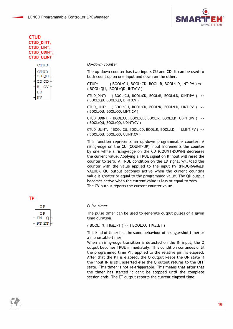
CTUDCTUD_DINT,CTUD_LINT,CTUD_UDINT,CTUD_ULINT
Up-down counter
The up-down counter has two inputs CU and CD. It can be used toboth count up on one input and down on the other.
CTUD: ( BOOL:CU, BOOL:CD, BOOL:R, BOOL:LD, INT:PV ) => ( BOOL:QU, BOOL:QD, INT:CV )
CTUD_DINT: ( BOOL:CU, BOOL:CD, BOOL:R, BOOL:LD, DINT:PV ) =>( BOOL:QU, BOOL:QD, DINT:CV )
CTUD_LINT: ( BOOL:CU, BOOL:CD, BOOL:R, BOOL:LD, LINT:PV ) =>( BOOL:QU, BOOL:QD, LINT:CV )
CTUD_UDINT: ( BOOL:CU, BOOL:CD, BOOL:R, BOOL:LD, UDINT:PV ) =>( BOOL:QU, BOOL:QD, UDINT:CV )
CTUD_ULINT: ( BOOL:CU, BOOL:CD, BOOL:R, BOOL:LD, ULINT:PV ) =>( BOOL:QU, BOOL:QD, ULINT:CV )
This function represents an up-down programmable counter. Arising-edge on the CU (COUNT-UP) input increments the counterby one while a rising-edge on the CD (COUNT-DOWN) decreasesthe current value. Applying a TRUE signal on R input will reset thecounter to zero. A TRUE condition on the LD signal will load thecounter with the value applied to the input PV (PROGRAMMEDVALUE). QU output becomes active when the current countingvalue is greater or equal to the programmed value. The QD outputbecomes active when the current value is less or equal to zero.The CV output reports the current counter value.
TP
Pulse timer
The pulse timer can be used to generate output pulses of a giventime duration.
( BOOL:IN, TIME:PT ) => ( BOOL:Q, TIME:ET )
This kind of timer has the same behaviour of a single-shot timer ora monostable timer.When a rising-edge transition is detected on the IN input, the Qoutput becomes TRUE immediately. This condition continues untilthe programmed time PT, applied to the relative pin, is elapsed.After that the PT is elapsed, the Q output keeps the ON state ifthe input IN is still asserted else the Q output returns to the OFFstate. This timer is not re-triggerable. This means that after thatthe timer has started it can't be stopped until the completesession ends. The ET output reports the current elapsed time.
18
LONGO Programmable Controller LPC Manager
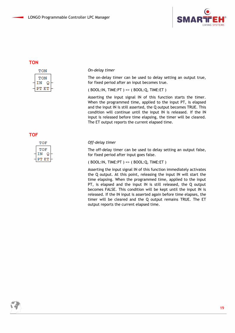
TON
On-delay timer
The on-delay timer can be used to delay setting an output true,for fixed period after an input becomes true.
( BOOL:IN, TIME:PT ) => ( BOOL:Q, TIME:ET )
Asserting the input signal IN of this function starts the timer.When the programmed time, applied to the input PT, is elapsedand the input IN is still asserted, the Q output becomes TRUE. Thiscondition will continue until the input IN is released. If the INinput is released before time elapsing, the timer will be cleared.The ET output reports the current elapsed time.
TOF
Off-delay timer
The off-delay timer can be used to delay setting an output false,for fixed period after input goes false.
( BOOL:IN, TIME:PT ) => ( BOOL:Q, TIME:ET )
Asserting the input signal IN of this function immediately activatesthe Q output. At this point, releasing the input IN will start thetime elapsing. When the programmed time, applied to the inputPT, is elapsed and the input IN is still released, the Q outputbecomes FALSE. This condition will be kept until the input IN isreleased. If the IN input is asserted again before time elapses, thetimer will be cleared and the Q output remains TRUE. The EToutput reports the current elapsed time.
19
LONGO Programmable Controller LPC Manager
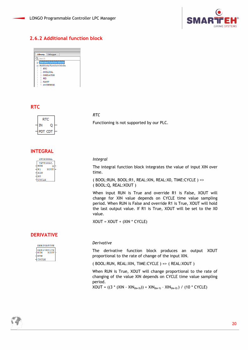
2.6.2 Additional function block
RTC
RTC
Functioning is not supported by our PLC.
INTEGRAL
Integral
The integral function block integrates the value of input XIN overtime.
( BOOL:RUN, BOOL:R1, REAL:XIN, REAL:X0, TIME:CYCLE ) => ( BOOL:Q, REAL:XOUT )
When input RUN is True and override R1 is False, XOUT willchange for XIN value depends on CYCLE time value samplingperiod. When RUN is False and override R1 is True, XOUT will holdthe last output value. If R1 is True, XOUT will be set to the X0value.
XOUT = XOUT + (XIN * CYCLE)
DERIVATIVE
Derivative
The derivative function block produces an output XOUTproportional to the rate of change of the input XIN.
( BOOL:RUN, REAL:XIN, TIME:CYCLE ) => ( REAL:XOUT )
When RUN is True, XOUT will change proportional to the rate ofchanging of the value XIN depends on CYCLE time value samplingperiod.XOUT = ((3 * (XIN - XIN(to-3))) + XIN(to-1) – XIN(to-2) ) / (10 * CYCLE)
20
LONGO Programmable Controller LPC Manager
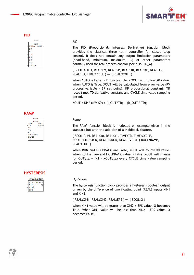
PID
PID
The PID (Proportional, Integral, Derivative) function blockprovides the classical three term controller for closed loopcontrol. It does not contain any output limitation parameters(dead-band, minimum, maximum, …) or other parametersnormally used for real process control (see also PID_A).
( BOOL:AUTO, REAL:PV, REAL:SP, REAL:X0, REAL:KP, REAL:TR, REAL:TD, TIME:CYCLE ) => ( REAL:XOUT )
When AUTO is False, PID function block XOUT will follow X0 value.When AUTO is True, XOUT will be calculated from error value (PVprocess variable – SP set point), KP proportional constant, TRreset time, TD derivative constant and CYCLE time value samplingperiod.
XOUT = KP * ((PV-SP) + (I_OUT/TR) + (D_OUT * TD))
RAMP
Ramp
The RAMP function block is modelled on example given in thestandard but with the addition of a 'Holdback' feature.
( BOOL:RUN, REAL:X0, REAL:X1, TIME:TR, TIME:CYCLE, BOOL:HOLDBACK, REAL:ERROR, REAL:PV ) => ( BOOL:RAMP, REAL:XOUT )
When RUN and HOLDBACK are False, XOUT will follow X0 value.When RUN is True and HOLDBACK value is False, XOUT will changefor OUT(to-1) + (X1 – XOUT(to-1)) every CYCLE time value samplingperiod.
HYSTERESIS
Hysteresis
The hysteresis function block provides a hysteresis boolean outputdriven by the difference of two floating point (REAL) inputs XIN1and XIN2.
( REAL:XIN1, REAL:XIN2, REAL:EPS ) => ( BOOL:Q )
When XIN1 value will be grater than XIN2 + EPS value, Q becomesTrue. When XIN1 value will be less than XIN2 - EPS value, Qbecomes False.
21
LONGO Programmable Controller LPC Manager
2.6.3 Type conversion
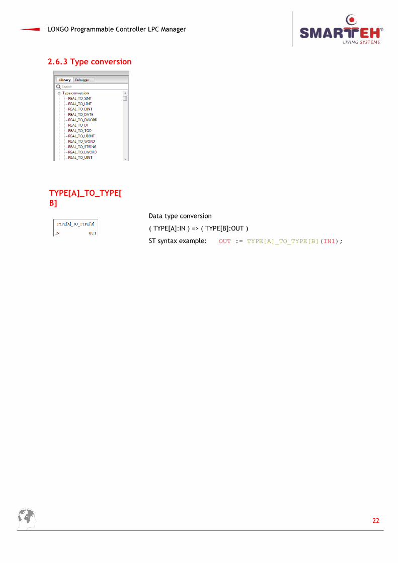
TYPE[A]_TO_TYPE[B]
Data type conversion
( TYPE[A]:IN ) => ( TYPE[B]:OUT )
ST syntax example: OUT := TYPE[A]_TO_TYPE[B](IN1);
22
LONGO Programmable Controller LPC Manager
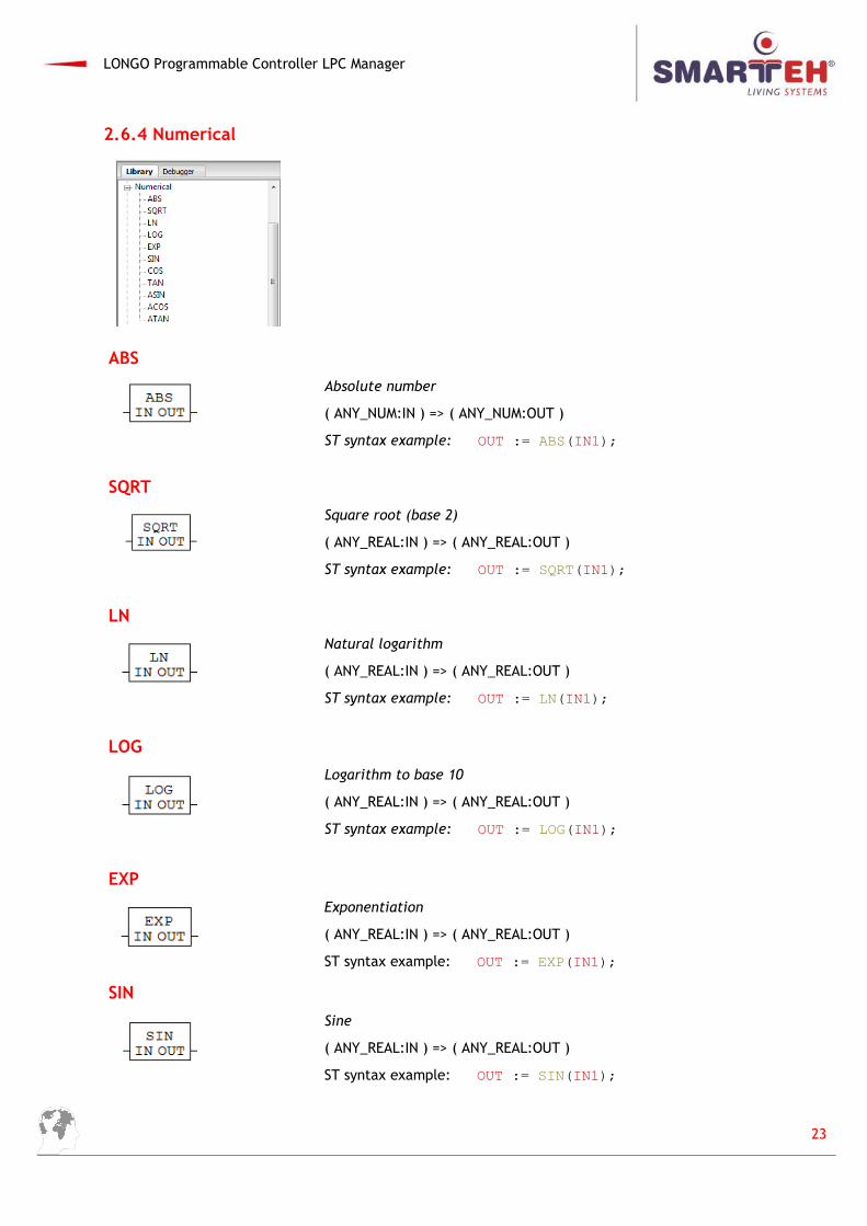
2.6.4 Numerical
ABS
Absolute number
( ANY_NUM:IN ) => ( ANY_NUM:OUT )
ST syntax example: OUT := ABS(IN1);
SQRT
Square root (base 2)
( ANY_REAL:IN ) => ( ANY_REAL:OUT )
ST syntax example: OUT := SQRT(IN1);
LN
Natural logarithm
( ANY_REAL:IN ) => ( ANY_REAL:OUT )
ST syntax example: OUT := LN(IN1);
LOG
Logarithm to base 10
( ANY_REAL:IN ) => ( ANY_REAL:OUT )
ST syntax example: OUT := LOG(IN1);
EXP
Exponentiation
( ANY_REAL:IN ) => ( ANY_REAL:OUT )
ST syntax example: OUT := EXP(IN1);
SIN
Sine
( ANY_REAL:IN ) => ( ANY_REAL:OUT )
ST syntax example: OUT := SIN(IN1);
23
LONGO Programmable Controller LPC Manager
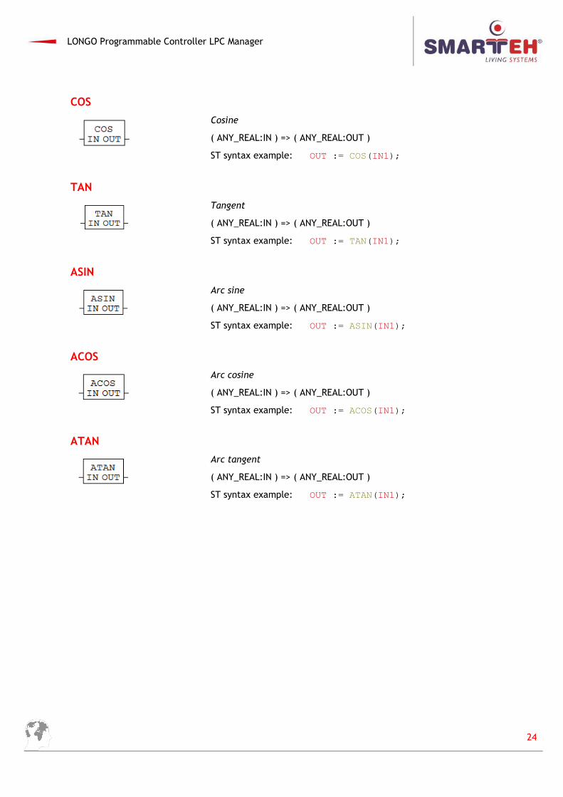
COS
Cosine
( ANY_REAL:IN ) => ( ANY_REAL:OUT )
ST syntax example: OUT := COS(IN1);
TAN
Tangent
( ANY_REAL:IN ) => ( ANY_REAL:OUT )
ST syntax example: OUT := TAN(IN1);
ASIN
Arc sine
( ANY_REAL:IN ) => ( ANY_REAL:OUT )
ST syntax example: OUT := ASIN(IN1);
ACOS
Arc cosine
( ANY_REAL:IN ) => ( ANY_REAL:OUT )
ST syntax example: OUT := ACOS(IN1);
ATAN
Arc tangent
( ANY_REAL:IN ) => ( ANY_REAL:OUT )
ST syntax example: OUT := ATAN(IN1);
24
LONGO Programmable Controller LPC Manager
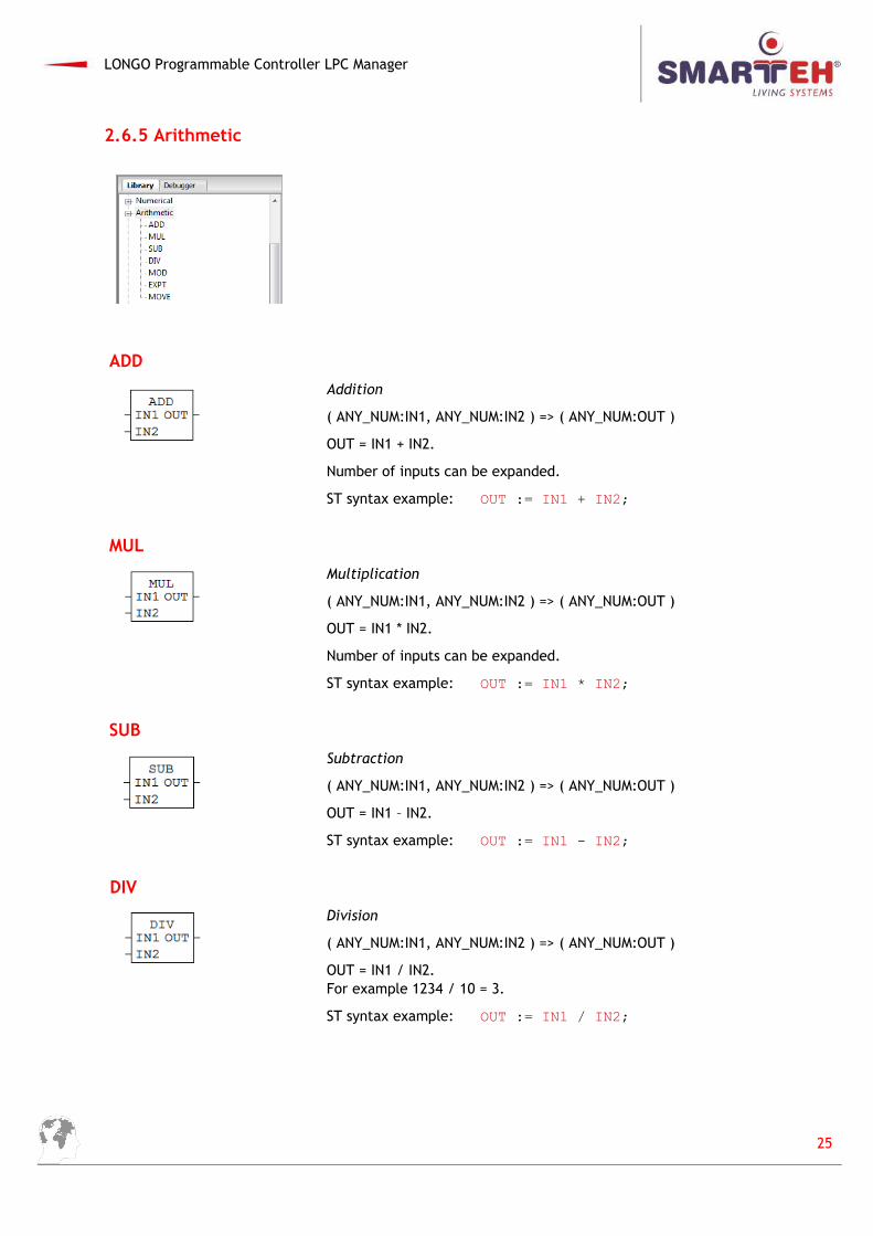
2.6.5 Arithmetic
ADD
Addition
( ANY_NUM:IN1, ANY_NUM:IN2 ) => ( ANY_NUM:OUT )
OUT = IN1 + IN2.
Number of inputs can be expanded.
ST syntax example: OUT := IN1 + IN2;
MUL
Multiplication
( ANY_NUM:IN1, ANY_NUM:IN2 ) => ( ANY_NUM:OUT )
OUT = IN1 * IN2.
Number of inputs can be expanded.
ST syntax example: OUT := IN1 * IN2;
SUB
Subtraction
( ANY_NUM:IN1, ANY_NUM:IN2 ) => ( ANY_NUM:OUT )
OUT = IN1 – IN2.
ST syntax example: OUT := IN1 - IN2;
DIV
Division
( ANY_NUM:IN1, ANY_NUM:IN2 ) => ( ANY_NUM:OUT )
OUT = IN1 / IN2. For example 1234 / 10 = 3.
ST syntax example: OUT := IN1 / IN2;
25
LONGO Programmable Controller LPC Manager
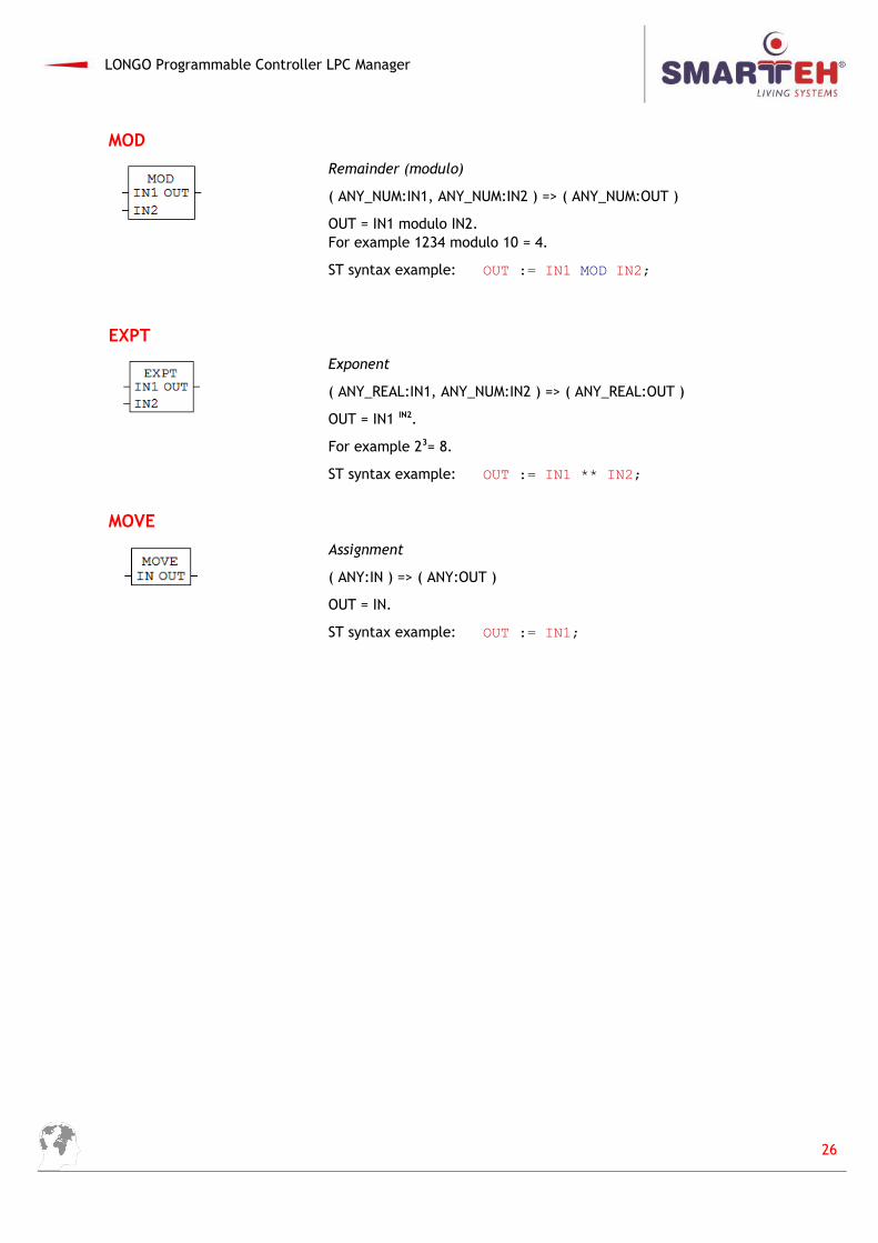
MOD
Remainder (modulo)
( ANY_NUM:IN1, ANY_NUM:IN2 ) => ( ANY_NUM:OUT )
OUT = IN1 modulo IN2. For example 1234 modulo 10 = 4.
ST syntax example: OUT := IN1 MOD IN2;
EXPT
Exponent
( ANY_REAL:IN1, ANY_NUM:IN2 ) => ( ANY_REAL:OUT )
OUT = IN1 IN2.
For example 23= 8.
ST syntax example: OUT := IN1 ** IN2;
MOVE
Assignment
( ANY:IN ) => ( ANY:OUT )
OUT = IN.
ST syntax example: OUT := IN1;
26
LONGO Programmable Controller LPC Manager
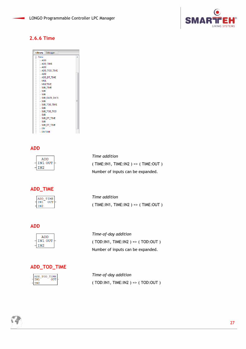
2.6.6 Time
ADD
Time addition
( TIME:IN1, TIME:IN2 ) => ( TIME:OUT )
Number of inputs can be expanded.
ADD_TIME
Time addition
( TIME:IN1, TIME:IN2 ) => ( TIME:OUT )
ADD
Time-of-day addition
( TOD:IN1, TIME:IN2 ) => ( TOD:OUT )
Number of inputs can be expanded.
ADD_TOD_TIME
Time-of-day addition
( TOD:IN1, TIME:IN2 ) => ( TOD:OUT )
27
LONGO Programmable Controller LPC Manager
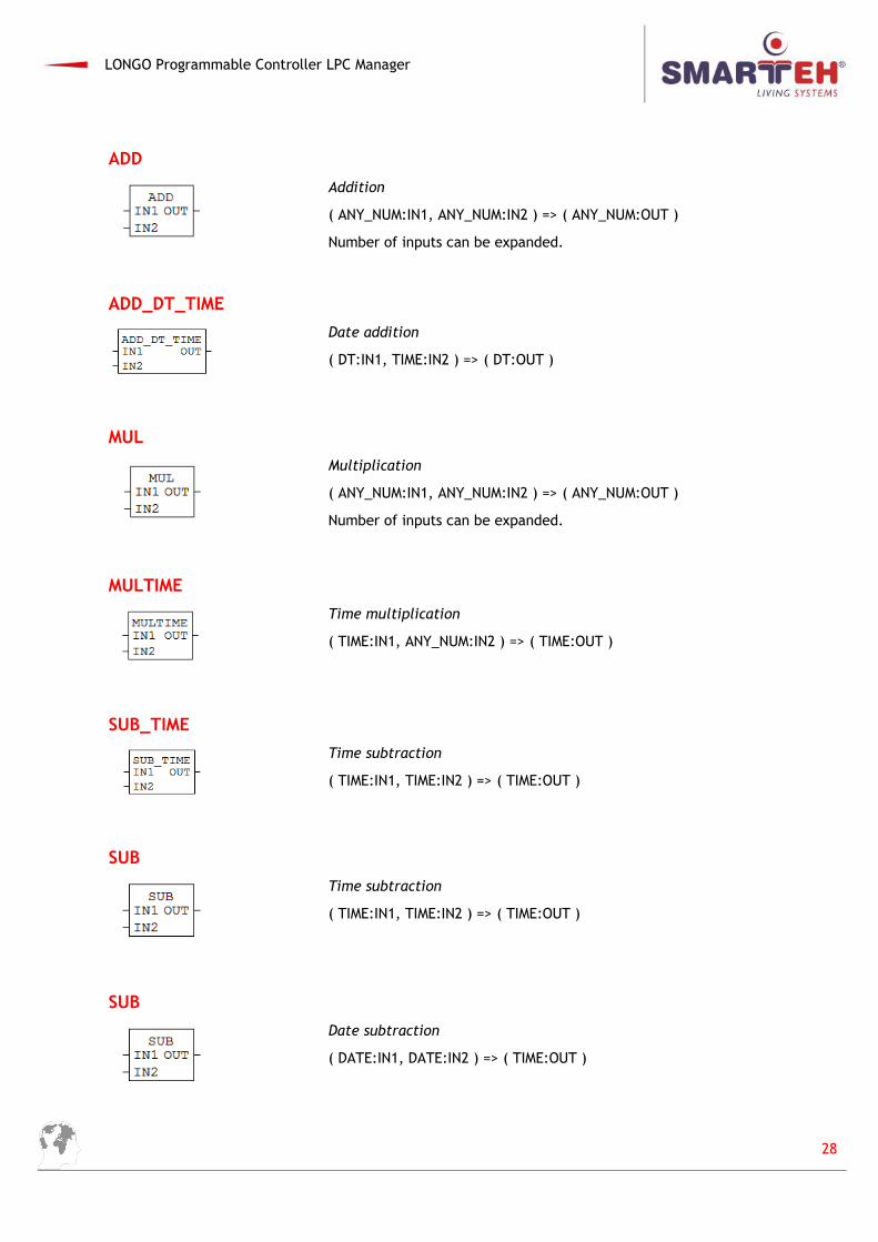
ADD
Addition
( ANY_NUM:IN1, ANY_NUM:IN2 ) => ( ANY_NUM:OUT )
Number of inputs can be expanded.
ADD_DT_TIME
Date addition
( DT:IN1, TIME:IN2 ) => ( DT:OUT )
MUL
Multiplication
( ANY_NUM:IN1, ANY_NUM:IN2 ) => ( ANY_NUM:OUT )
Number of inputs can be expanded.
MULTIME
Time multiplication
( TIME:IN1, ANY_NUM:IN2 ) => ( TIME:OUT )
SUB_TIME
Time subtraction
( TIME:IN1, TIME:IN2 ) => ( TIME:OUT )
SUB
Time subtraction
( TIME:IN1, TIME:IN2 ) => ( TIME:OUT )
SUB
Date subtraction
( DATE:IN1, DATE:IN2 ) => ( TIME:OUT )
28
LONGO Programmable Controller LPC Manager
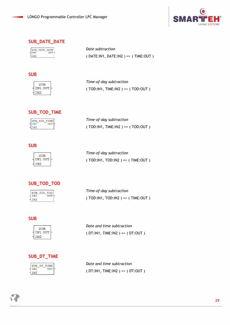
SUB_DATE_DATE
Date subtraction
( DATE:IN1, DATE:IN2 ) => ( TIME:OUT )
SUB
Time-of-day subtraction
( TOD:IN1, TIME:IN2 ) => ( TOD:OUT )
SUB_TOD_TIME
Time-of-day subtraction
( TOD:IN1, TIME:IN2 ) => ( TOD:OUT )
SUB
Time-of-day subtraction
( TOD:IN1, TOD:IN2 ) => ( TIME:OUT )
SUB_TOD_TOD
Time-of-day subtraction
( TOD:IN1, TOD:IN2 ) => ( TIME:OUT )
SUB
Date and time subtraction
( DT:IN1, TIME:IN2 ) => ( DT:OUT )
SUB_DT_TIME
Date and time subtraction
( DT:IN1, TIME:IN2 ) => ( DT:OUT )
29
LONGO Programmable Controller LPC Manager
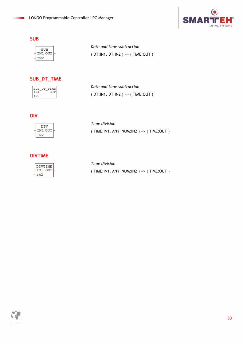
SUB
Date and time subtraction
( DT:IN1, DT:IN2 ) => ( TIME:OUT )
SUB_DT_TIME
Date and time subtraction
( DT:IN1, DT:IN2 ) => ( TIME:OUT )
DIV
Time division
( TIME:IN1, ANY_NUM:IN2 ) => ( TIME:OUT )
DIVTIME
Time division
( TIME:IN1, ANY_NUM:IN2 ) => ( TIME:OUT )
30
LONGO Programmable Controller LPC Manager
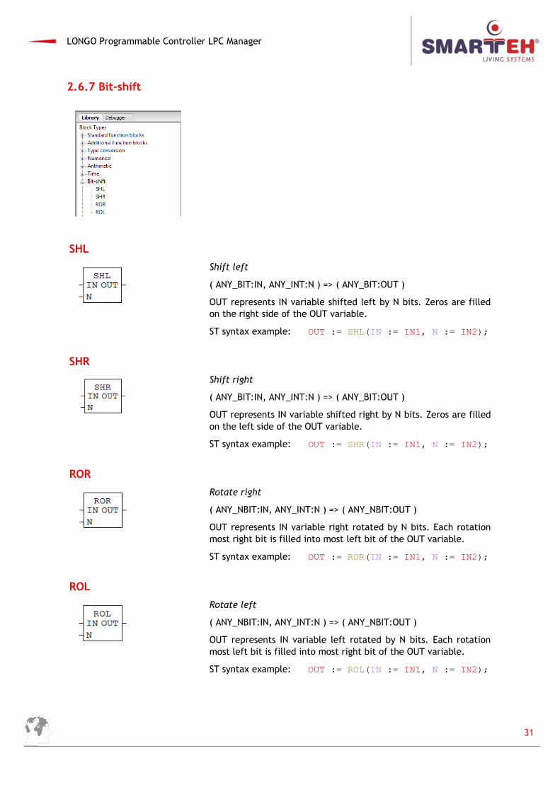
2.6.7 Bit-shift
SHL
Shift left
( ANY_BIT:IN, ANY_INT:N ) => ( ANY_BIT:OUT )
OUT represents IN variable shifted left by N bits. Zeros are filledon the right side of the OUT variable.
ST syntax example: OUT := SHL(IN := IN1, N := IN2);
SHR
Shift right
( ANY_BIT:IN, ANY_INT:N ) => ( ANY_BIT:OUT )
OUT represents IN variable shifted right by N bits. Zeros are filledon the left side of the OUT variable.
ST syntax example: OUT := SHR(IN := IN1, N := IN2);
ROR
Rotate right
( ANY_NBIT:IN, ANY_INT:N ) => ( ANY_NBIT:OUT )
OUT represents IN variable right rotated by N bits. Each rotationmost right bit is filled into most left bit of the OUT variable.
ST syntax example: OUT := ROR(IN := IN1, N := IN2);
ROL
Rotate left
( ANY_NBIT:IN, ANY_INT:N ) => ( ANY_NBIT:OUT )
OUT represents IN variable left rotated by N bits. Each rotationmost left bit is filled into most right bit of the OUT variable.
ST syntax example: OUT := ROL(IN := IN1, N := IN2);
31
LONGO Programmable Controller LPC Manager
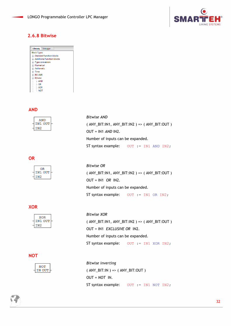
2.6.8 Bitwise
AND
Bitwise AND
( ANY_BIT:IN1, ANY_BIT:IN2 ) => ( ANY_BIT:OUT )
OUT = IN1 AND IN2.
Number of inputs can be expanded.
ST syntax example: OUT := IN1 AND IN2;
OR
Bitwise OR
( ANY_BIT:IN1, ANY_BIT:IN2 ) => ( ANY_BIT:OUT )
OUT = IN1 OR IN2.
Number of inputs can be expanded.
ST syntax example: OUT := IN1 OR IN2;
XOR
Bitwise XOR
( ANY_BIT:IN1, ANY_BIT:IN2 ) => ( ANY_BIT:OUT )
OUT = IN1 EXCLUSIVE OR IN2.
Number of inputs can be expanded.
ST syntax example: OUT := IN1 XOR IN2;
NOT
Bitwise inverting
( ANY_BIT:IN ) => ( ANY_BIT:OUT )
OUT = NOT IN.
ST syntax example: OUT := IN1 NOT IN2;
32
LONGO Programmable Controller LPC Manager
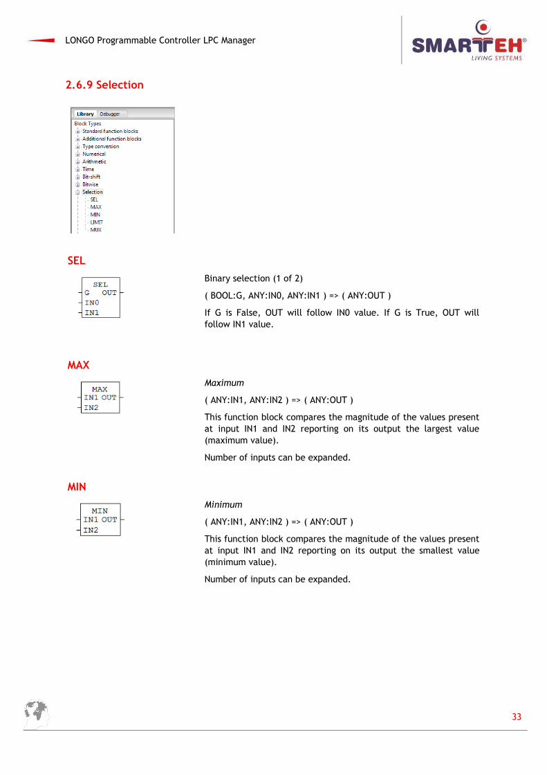
2.6.9 Selection
SEL
Binary selection (1 of 2)
( BOOL:G, ANY:IN0, ANY:IN1 ) => ( ANY:OUT )
If G is False, OUT will follow IN0 value. If G is True, OUT willfollow IN1 value.
MAX
Maximum
( ANY:IN1, ANY:IN2 ) => ( ANY:OUT )
This function block compares the magnitude of the values presentat input IN1 and IN2 reporting on its output the largest value(maximum value).
Number of inputs can be expanded.
MIN
Minimum
( ANY:IN1, ANY:IN2 ) => ( ANY:OUT )
This function block compares the magnitude of the values presentat input IN1 and IN2 reporting on its output the smallest value(minimum value).
Number of inputs can be expanded.
33
LONGO Programmable Controller LPC Manager
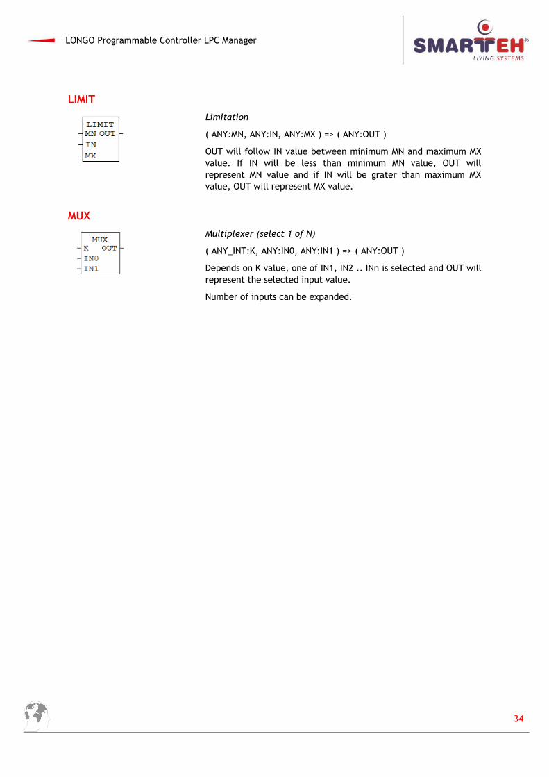
LIMIT
Limitation
( ANY:MN, ANY:IN, ANY:MX ) => ( ANY:OUT )
OUT will follow IN value between minimum MN and maximum MXvalue. If IN will be less than minimum MN value, OUT willrepresent MN value and if IN will be grater than maximum MXvalue, OUT will represent MX value.
MUX
Multiplexer (select 1 of N)
( ANY_INT:K, ANY:IN0, ANY:IN1 ) => ( ANY:OUT )
Depends on K value, one of IN1, IN2 .. INn is selected and OUT willrepresent the selected input value.
Number of inputs can be expanded.
34
LONGO Programmable Controller LPC Manager
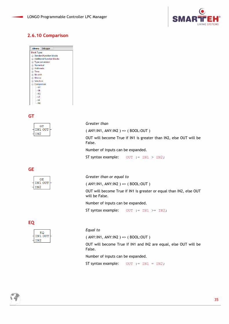
2.6.10 Comparison
GT
Greater than
( ANY:IN1, ANY:IN2 ) => ( BOOL:OUT )
OUT will become True if IN1 is greater than IN2, else OUT will beFalse.
Number of inputs can be expanded.
ST syntax example: OUT := IN1 > IN2;
GE
Greater than or equal to
( ANY:IN1, ANY:IN2 ) => ( BOOL:OUT )
OUT will become True if IN1 is greater or equal than IN2, else OUTwill be False.
Number of inputs can be expanded.
ST syntax example: OUT := IN1 >= IN2;
EQ
Equal to
( ANY:IN1, ANY:IN2 ) => ( BOOL:OUT )
OUT will become True if IN1 and IN2 are equal, else OUT will beFalse.
Number of inputs can be expanded.
ST syntax example: OUT := IN1 = IN2;
35
LONGO Programmable Controller LPC Manager
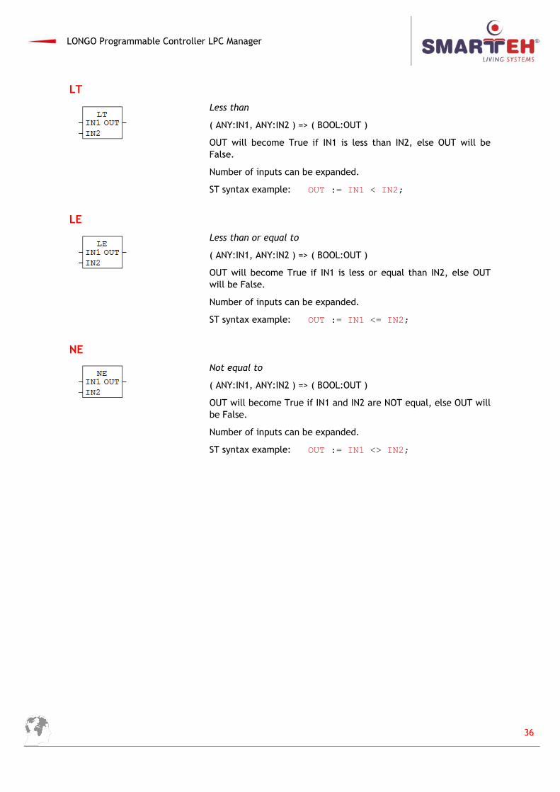
LT
Less than
( ANY:IN1, ANY:IN2 ) => ( BOOL:OUT )
OUT will become True if IN1 is less than IN2, else OUT will beFalse.
Number of inputs can be expanded.
ST syntax example: OUT := IN1 < IN2;
LE
Less than or equal to
( ANY:IN1, ANY:IN2 ) => ( BOOL:OUT )
OUT will become True if IN1 is less or equal than IN2, else OUTwill be False.
Number of inputs can be expanded.
ST syntax example: OUT := IN1 <= IN2;
NE
Not equal to
( ANY:IN1, ANY:IN2 ) => ( BOOL:OUT )
OUT will become True if IN1 and IN2 are NOT equal, else OUT willbe False.
Number of inputs can be expanded.
ST syntax example: OUT := IN1 <> IN2;
36
LONGO Programmable Controller LPC Manager
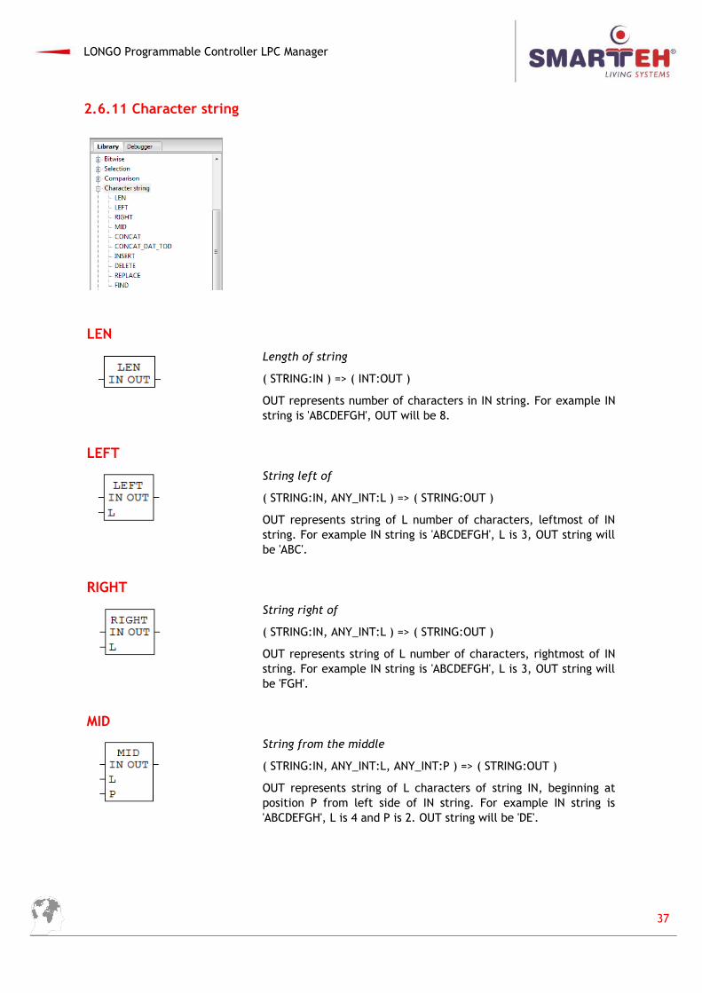
2.6.11 Character string
LEN
Length of string
( STRING:IN ) => ( INT:OUT )
OUT represents number of characters in IN string. For example INstring is 'ABCDEFGH', OUT will be 8.
LEFT
String left of
( STRING:IN, ANY_INT:L ) => ( STRING:OUT )
OUT represents string of L number of characters, leftmost of INstring. For example IN string is 'ABCDEFGH', L is 3, OUT string willbe 'ABC'.
RIGHT
String right of
( STRING:IN, ANY_INT:L ) => ( STRING:OUT )
OUT represents string of L number of characters, rightmost of INstring. For example IN string is 'ABCDEFGH', L is 3, OUT string willbe 'FGH'.
MID
String from the middle
( STRING:IN, ANY_INT:L, ANY_INT:P ) => ( STRING:OUT )
OUT represents string of L characters of string IN, beginning atposition P from left side of IN string. For example IN string is'ABCDEFGH', L is 4 and P is 2. OUT string will be 'DE'.
37
LONGO Programmable Controller LPC Manager
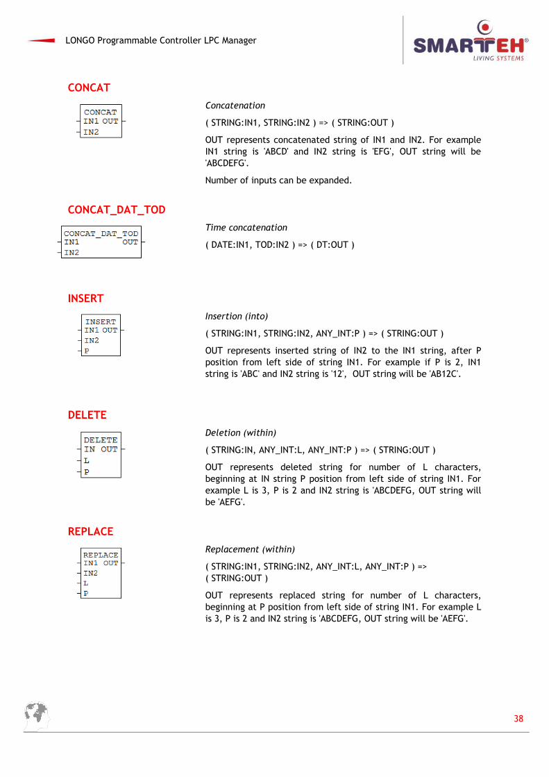
CONCAT
Concatenation
( STRING:IN1, STRING:IN2 ) => ( STRING:OUT )
OUT represents concatenated string of IN1 and IN2. For exampleIN1 string is 'ABCD' and IN2 string is 'EFG', OUT string will be'ABCDEFG'.
Number of inputs can be expanded.
CONCAT_DAT_TOD
Time concatenation
( DATE:IN1, TOD:IN2 ) => ( DT:OUT )
INSERT
Insertion (into)
( STRING:IN1, STRING:IN2, ANY_INT:P ) => ( STRING:OUT )
OUT represents inserted string of IN2 to the IN1 string, after Pposition from left side of string IN1. For example if P is 2, IN1string is 'ABC' and IN2 string is '12', OUT string will be 'AB12C'.
DELETE
Deletion (within)
( STRING:IN, ANY_INT:L, ANY_INT:P ) => ( STRING:OUT )
OUT represents deleted string for number of L characters,beginning at IN string P position from left side of string IN1. Forexample L is 3, P is 2 and IN2 string is 'ABCDEFG, OUT string willbe 'AEFG'.
REPLACE
Replacement (within)
( STRING:IN1, STRING:IN2, ANY_INT:L, ANY_INT:P ) => ( STRING:OUT )
OUT represents replaced string for number of L characters,beginning at P position from left side of string IN1. For example Lis 3, P is 2 and IN2 string is 'ABCDEFG, OUT string will be 'AEFG'.
38
LONGO Programmable Controller LPC Manager
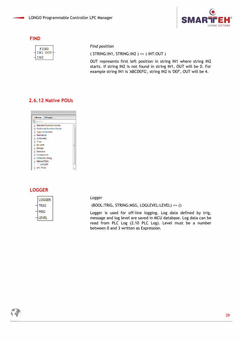
FIND
Find position
( STRING:IN1, STRING:IN2 ) => ( INT:OUT )
OUT represents first left position in string IN1 where string IN2starts. If string IN2 is not found in string IN1, OUT will be 0. Forexample string IN1 is 'ABCDEFG', string IN2 is 'DEF', OUT will be 4.
2.6.12 Native POUs
LOGGER
Logger
(BOOL:TRIG, STRING:MSG, LOGLEVEL:LEVEL) => ()
Logger is used for off-line logging. Log data defined by trig,message and log level are saved in MCU database. Log data can beread from PLC Log (2.10 PLC Log). Level must be a numberbetween 0 and 3 written as Expression.
39
LONGO Programmable Controller LPC Manager
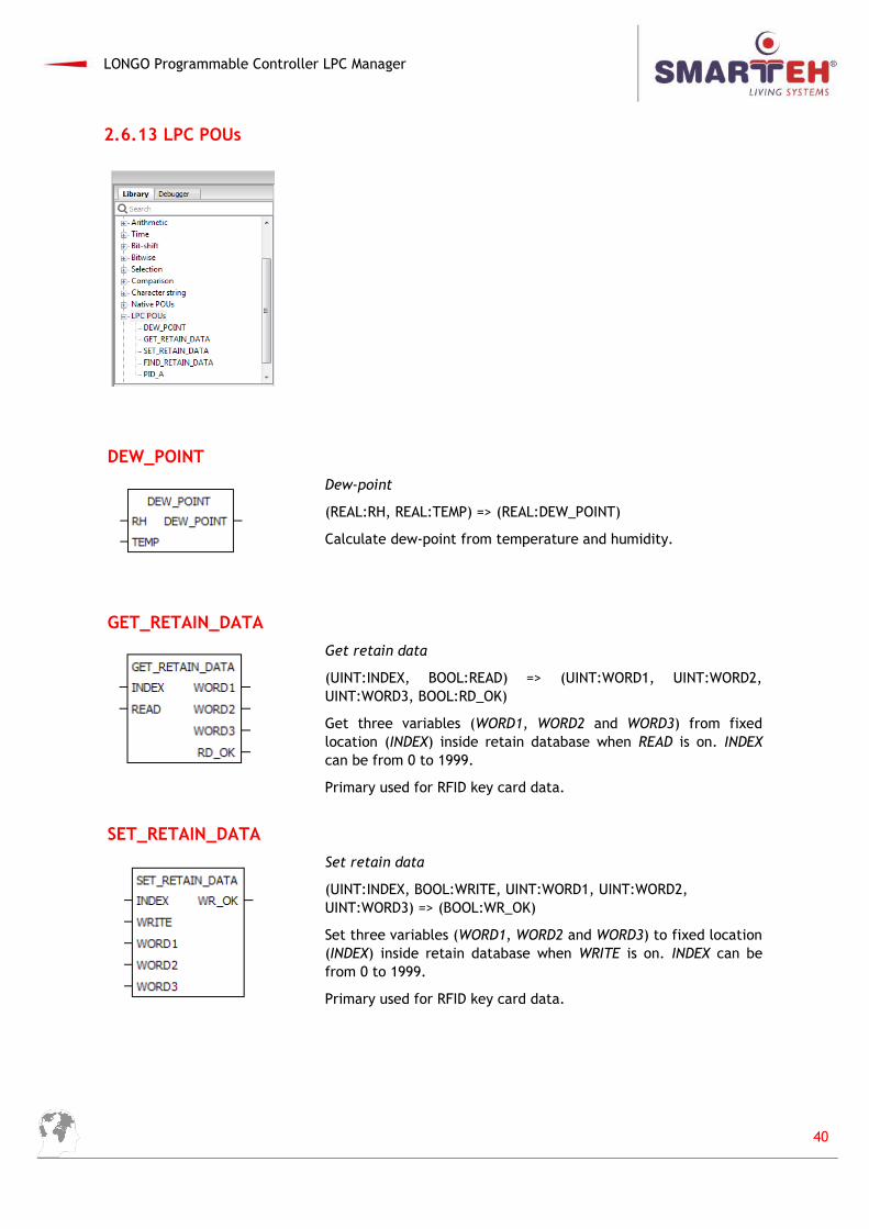
2.6.13 LPC POUs
DEW_POINT
Dew-point
(REAL:RH, REAL:TEMP) => (REAL:DEW_POINT)
Calculate dew-point from temperature and humidity.
GET_RETAIN_DATA
Get retain data
(UINT:INDEX, BOOL:READ) => (UINT:WORD1, UINT:WORD2,UINT:WORD3, BOOL:RD_OK)
Get three variables (WORD1, WORD2 and WORD3) from fixedlocation (INDEX) inside retain database when READ is on. INDEXcan be from 0 to 1999.
Primary used for RFID key card data.
SET_RETAIN_DATA
Set retain data
(UINT:INDEX, BOOL:WRITE, UINT:WORD1, UINT:WORD2, UINT:WORD3) => (BOOL:WR_OK)
Set three variables (WORD1, WORD2 and WORD3) to fixed location(INDEX) inside retain database when WRITE is on. INDEX can befrom 0 to 1999.
Primary used for RFID key card data.
40
LONGO Programmable Controller LPC Manager
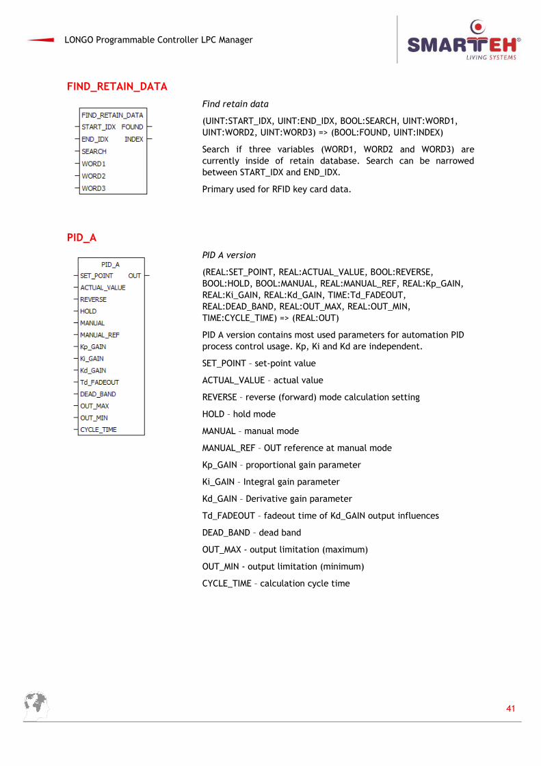
FIND_RETAIN_DATA
Find retain data
(UINT:START_IDX, UINT:END_IDX, BOOL:SEARCH, UINT:WORD1, UINT:WORD2, UINT:WORD3) => (BOOL:FOUND, UINT:INDEX)
Search if three variables (WORD1, WORD2 and WORD3) arecurrently inside of retain database. Search can be narrowedbetween START_IDX and END_IDX.
Primary used for RFID key card data.
PID_A
PID A version
(REAL:SET_POINT, REAL:ACTUAL_VALUE, BOOL:REVERSE, BOOL:HOLD, BOOL:MANUAL, REAL:MANUAL_REF, REAL:Kp_GAIN, REAL:Ki_GAIN, REAL:Kd_GAIN, TIME:Td_FADEOUT, REAL:DEAD_BAND, REAL:OUT_MAX, REAL:OUT_MIN, TIME:CYCLE_TIME) => (REAL:OUT)
PID A version contains most used parameters for automation PID process control usage. Kp, Ki and Kd are independent.
SET_POINT – set-point value
ACTUAL_VALUE – actual value
REVERSE – reverse (forward) mode calculation setting
HOLD – hold mode
MANUAL – manual mode
MANUAL_REF – OUT reference at manual mode
Kp_GAIN – proportional gain parameter
Ki_GAIN – Integral gain parameter
Kd_GAIN – Derivative gain parameter
Td_FADEOUT – fadeout time of Kd_GAIN output influences
DEAD_BAND – dead band
OUT_MAX - output limitation (maximum)
OUT_MIN - output limitation (minimum)
CYCLE_TIME – calculation cycle time
41
LONGO Programmable Controller LPC Manager
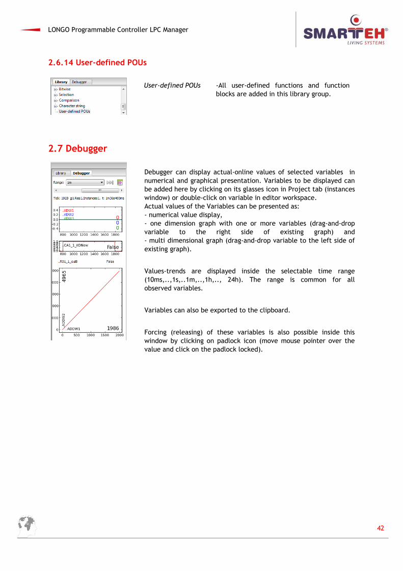
2.6.14 User-defined POUs
User-defined POUs -All user-defined functions and function blocks are added in this library group.
2.7 Debugger
Debugger can display actual-online values of selected variables innumerical and graphical presentation. Variables to be displayed canbe added here by clicking on its glasses icon in Project tab (instanceswindow) or double-click on variable in editor workspace. Actual values of the Variables can be presented as: - numerical value display, - one dimension graph with one or more variables (drag-and-dropvariable to the right side of existing graph) and- multi dimensional graph (drag-and-drop variable to the left side ofexisting graph).
Values-trends are displayed inside the selectable time range(10ms,..,1s,..1m,..,1h,.., 24h). The range is common for allobserved variables.
Variables can also be exported to the clipboard.
Forcing (releasing) of these variables is also possible inside thiswindow by clicking on padlock icon (move mouse pointer over thevalue and click on the padlock locked).
42
LONGO Programmable Controller LPC Manager
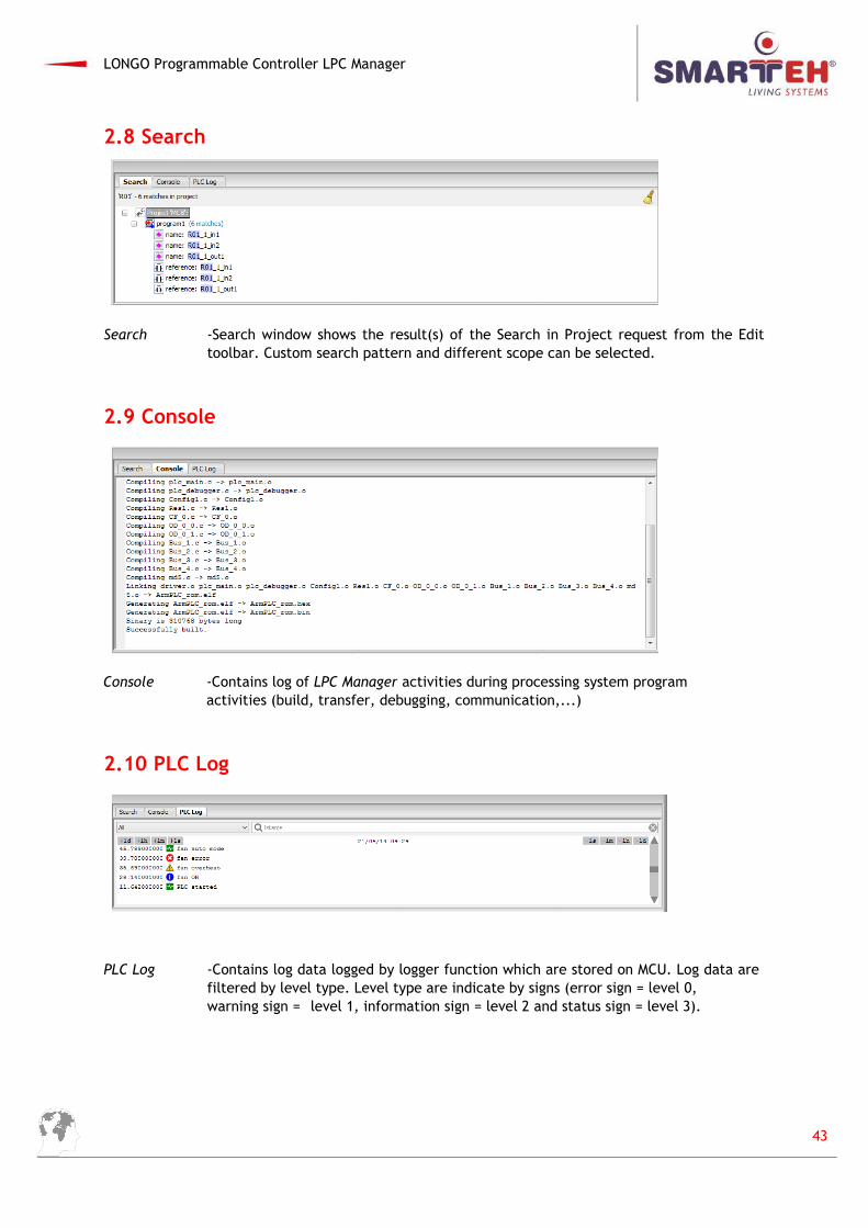
2.8 Search
Search -Search window shows the result(s) of the Search in Project request from the Edittoolbar. Custom search pattern and different scope can be selected.
2.9 Console
Console -Contains log of LPC Manager activities during processing system programactivities (build, transfer, debugging, communication,...)
2.10 PLC Log
PLC Log -Contains log data logged by logger function which are stored on MCU. Log data are filtered by level type. Level type are indicate by signs (error sign = level 0, warning sign = level 1, information sign = level 2 and status sign = level 3).
43
LONGO Programmable Controller LPC Manager
3 PROGRAMMING LANGUAGES
LPC Manager is based on PLC (programmable logic controller) programming languages InternationalStandard IEC 61131-3.
Following types of PLC programming languages can be used:
Textual:
- IL Instruction List
- ST Structured Text
Graphic:
- FBD Function Block Diagram
- LD Ladder Diagram
- SFC Sequential Function Chart
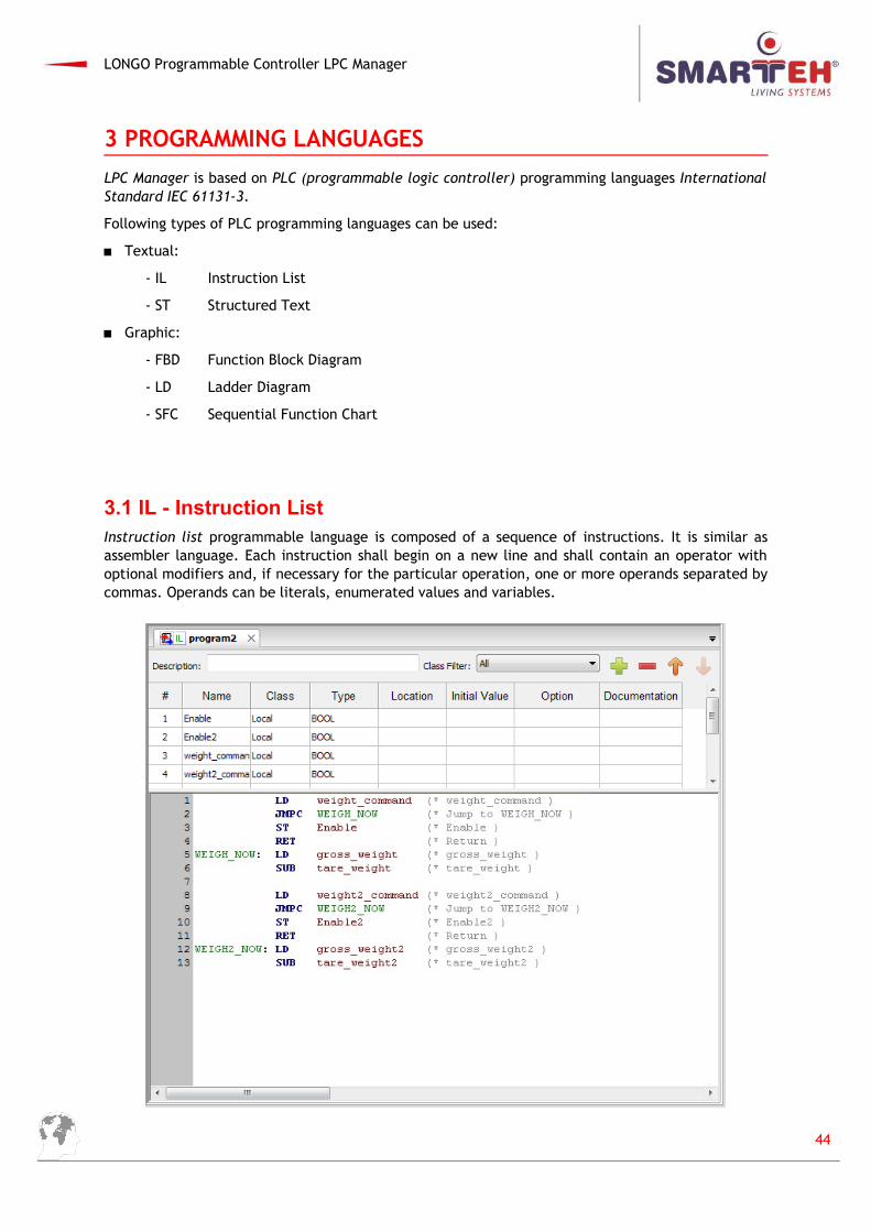
3.1 IL - Instruction ListInstruction list programmable language is composed of a sequence of instructions. It is similar asassembler language. Each instruction shall begin on a new line and shall contain an operator withoptional modifiers and, if necessary for the particular operation, one or more operands separated bycommas. Operands can be literals, enumerated values and variables.
44
LONGO Programmable Controller LPC Manager
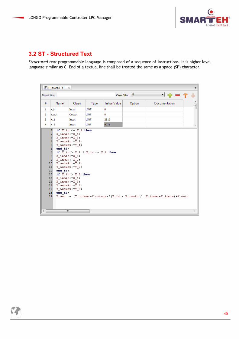
3.2 ST - Structured TextStructured text programmable language is composed of a sequence of instructions. It is higher levellanguage similar as C. End of a textual line shall be treated the same as a space (SP) character.
45
LONGO Programmable Controller LPC Manager
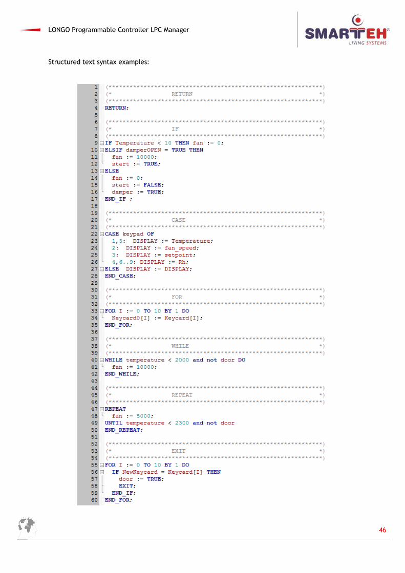
Structured text syntax examples:
46
LONGO Programmable Controller LPC Manager
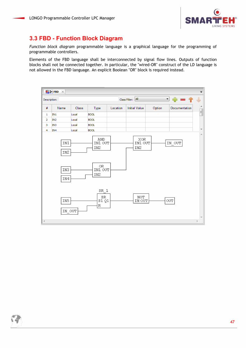
3.3 FBD - Function Block DiagramFunction block diagram programmable language is a graphical language for the programming ofprogrammable controllers.
Elements of the FBD language shall be interconnected by signal flow lines. Outputs of functionblocks shall not be connected together. In particular, the "wired-OR" construct of the LD language isnot allowed in the FBD language. An explicit Boolean "OR" block is required instead.
47
LONGO Programmable Controller LPC Manager
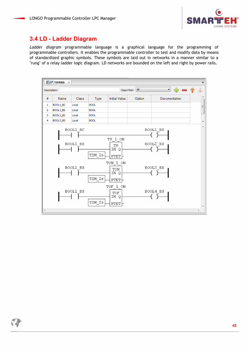
3.4 LD - Ladder DiagramLadder diagram programmable language is a graphical language for the programming ofprogrammable controllers. It enables the programmable controller to test and modify data by meansof standardized graphic symbols. These symbols are laid out in networks in a manner similar to a"rung" of a relay ladder logic diagram. LD networks are bounded on the left and right by power rails.
48
LONGO Programmable Controller LPC Manager
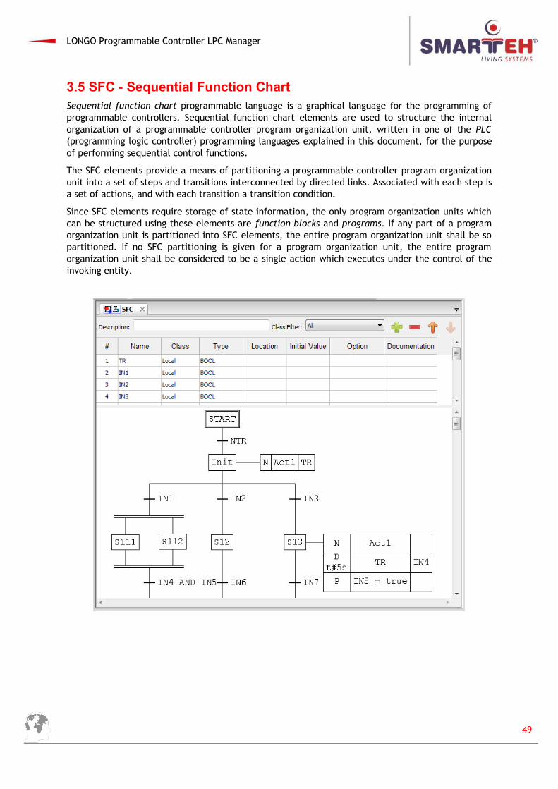
3.5 SFC - Sequential Function ChartSequential function chart programmable language is a graphical language for the programming ofprogrammable controllers. Sequential function chart elements are used to structure the internalorganization of a programmable controller program organization unit, written in one of the PLC(programming logic controller) programming languages explained in this document, for the purposeof performing sequential control functions.
The SFC elements provide a means of partitioning a programmable controller program organizationunit into a set of steps and transitions interconnected by directed links. Associated with each step isa set of actions, and with each transition a transition condition.
Since SFC elements require storage of state information, the only program organization units whichcan be structured using these elements are function blocks and programs. If any part of a programorganization unit is partitioned into SFC elements, the entire program organization unit shall be sopartitioned. If no SFC partitioning is given for a program organization unit, the entire programorganization unit shall be considered to be a single action which executes under the control of theinvoking entity.
49
LONGO Programmable Controller LPC Manager
APPENDIX A – ERROR REPORTING
If you think you found a bug in our software or you have an idea of what can be improved or added,you are most welcome to share your thoughts with us ([email protected]). We will consider thepossibilities and try to include them in our next release.
You should contact your vendor with the description. The following information should be included:
Software version.
Detailed description of the bug or idea.
If possible, steps that will recreate the problem (if bug is being reported).
Your contact information (e-mail, phone, fax).
In case we need more information we may need to contact you before we can determine the exactsolution. And remember: the only software without a need for maintenance is the software notbeing used!
50
LONGO Programmable Controller LPC Manager
APPENDIX B – DOCUMENT HISTORY
The following table describes all the changes to the document.
Date V. Description
30.09.2011 - The preliminary version, issues as LPC Manager User Manual.
30.01.2012 001 First release.
30.06.2012 002 Changes from previous version.
25.05.2014 003 Change according new release of LPC Composer 5.0.1.32
22.01.2016 004 Change according new release of LPC Smarteh IDE 5.1.4.2
51