
USER MANUAL - Malux
185
1 USER MANUAL RUT955 LTE Router
Transcript of USER MANUAL - Malux

1
USER MANUAL RUT955 LTE Router

2
Legal notice
Copyright © 2015 TELTONIKA Ltd. All rights reserved. Reproduction, transfer, distribution or storage of part
or all of the contents in this document in any form without the prior written permission of TELTONIKA Ltd is
prohibited. The manufacturer reserves the right to modify the product and manual for the purpose of technical
improvement without prior notice.
Other product and company names mentioned herein may be trademarks or trade names of their respective
owners.
Attention
Before using the device we strongly recommend reading this user manual first.
Do not rip open the device. Do not touch the device if the device block is broken.
All wireless devices for data transferring may be susceptible to interference, which could
affect performance.
The device is not water-resistant. Keep it dry.
Device is powered by low voltage +9V DC power adaptor.
Please do not scratch the device. Scratched device is not fully protected.

3
Table of Contents
Legal notice .............................................................................................................................................................. 2
Attention.................................................................................................................................................................. 2
SAFETY INFORMATION ............................................................................................................................................ 9
Device connection ............................................................................................................................................. 10
1 Introduction ................................................................................................................................................. 11
2 Specifications ............................................................................................................................................... 11
2.1 Ethernet ................................................................................................................................................... 11
2.2 Wi-Fi ......................................................................................................................................................... 11
2.3 Hardware ................................................................................................................................................. 11
2.4 Electrical, Mechanical & Environmental .................................................................................................. 12
2.5 Applications ............................................................................................................................................. 12
3 Setting up your router ................................................................................................................................. 13
3.1 Installation ............................................................................................................................................... 13
3.1.1 Front Panel and Back Panel ............................................................................................................. 13
3.1.2 Connection status LED indication .................................................................................................... 13
3.1.3 Hardware installation ...................................................................................................................... 14
3.2 Logging in ................................................................................................................................................. 15
4 Operation Modes ......................................................................................................................................... 18
5 Powering Options ........................................................................................................................................ 19
5.1 Powering the device from higher voltage................................................................................................ 19
6 Status ........................................................................................................................................................... 20
6.1 Overview .................................................................................................................................................. 20
6.2 System Information ................................................................................................................................. 20
6.3 Network Information ............................................................................................................................... 22
6.4 Device information .................................................................................................................................. 30
6.5 Services .................................................................................................................................................... 32
1.1 Routes ...................................................................................................................................................... 32
6.5.1 ARP ................................................................................................................................................... 32
6.5.2 Active IP-Routes ............................................................................................................................... 33
4
6.5.3 Active IPv6-Routes ........................................................................................................................... 33
6.6 Graphs ...................................................................................................................................................... 33
6.6.1 Mobile Signal Strength ..................................................................................................................... 33
6.6.2 Realtime Load .................................................................................................................................. 34
6.6.3 Realtime Traffic ................................................................................................................................ 35
6.6.4 Realtime Wireless ............................................................................................................................ 36
6.6.5 Realtime Connections ...................................................................................................................... 37
6.7 Mobile Traffic ........................................................................................................................................... 38
6.8 Speed Test ................................................................................................................................................ 38
6.9 Events Log ................................................................................................................................................ 39
6.9.1 All Events .......................................................................................................................................... 39
6.9.2 System Events .................................................................................................................................. 40
6.9.3 Network Events ................................................................................................................................ 41
6.9.4 Events Reporting .............................................................................................................................. 42
6.9.5 Reporting Configuration .................................................................................................................. 43
7 Network ....................................................................................................................................................... 46
7.1 Mobile ...................................................................................................................................................... 46
7.1.1 General ............................................................................................................................................. 46
7.1.2 SIM Management ............................................................................................................................ 49
7.1.3 Network Operators .......................................................................................................................... 50
7.1.4 Mobile Data Limit............................................................................................................................. 51
7.1.5 SIM Idle protection .......................................................................................................................... 52
7.2 WAN ......................................................................................................................................................... 53
7.2.1 Operation Mode .............................................................................................................................. 53
7.2.2 Common configuration .................................................................................................................... 54
7.3 LAN ....................................................................................................................................................... 60
7.3.1 Configuration ................................................................................................................................... 60
7.3.2 DHCP Server ..................................................................................................................................... 61
7.4 Wireless ................................................................................................................................................... 63
7.5 VLAN......................................................................................................................................................... 66
7.5.1 VLAN Networks ................................................................................................................................ 66
7.5.2 LAN Networks .................................................................................................................................. 68
7.6 Firewall ..................................................................................................................................................... 68
7.6.1 General Settings ............................................................................................................................... 68
7.6.2 DMZ .................................................................................................................................................. 69
5
7.6.3 Port Forwarding ............................................................................................................................... 69
7.6.4 Traffic Rules...................................................................................................................................... 72
7.6.5 Custom Rules ................................................................................................................................... 76
7.6.6 DDOS Prevention ............................................................................................................................. 76
7.6.7 Port Scan Prevention ....................................................................................................................... 79
7.7 Routing ..................................................................................................................................................... 79
7.7.1 Static Routes .................................................................................................................................... 79
7.7.2 Dynamic Routes ............................................................................................................................... 80
7.8 Load Balancing ......................................................................................................................................... 84
8 Remote monitoring and administration ...................................................................................................... 84
9 Services ........................................................................................................................................................ 86
9.1 VRRP ......................................................................................................................................................... 86
9.1.1 VRRP LAN Configuration Settings .................................................................................................... 86
9.1.2 Check Internet connection ............................................................................................................... 87
9.2 TR-069 ...................................................................................................................................................... 87
9.2.1 TR-069 Parameters Configuration ................................................................................................... 87
9.3 Web filter ................................................................................................................................................. 88
9.3.1 Site blocking ..................................................................................................................................... 88
9.3.2 Proxy Based Content Blocker ........................................................................................................... 88
9.4 NTP ........................................................................................................................................................... 89
9.5 RS232/RS485 ............................................................................................................................................ 91
9.5.1 RS232 ............................................................................................................................................... 91
9.5.2 RS485 ............................................................................................................................................... 93
9.5.3 Modes of different serial types in RS232 and RS485 ....................................................................... 96
9.6 VPN ........................................................................................................................................................ 100
9.6.1 OpenVPN ........................................................................................................................................ 100
9.6.2 IPSec ............................................................................................................................................... 103
9.6.3 GRE Tunnel ..................................................................................................................................... 106
9.6.4 PPTP ............................................................................................................................................... 108
9.6.5 L2TP ................................................................................................................................................ 109
9.7 Dynamic DNS .......................................................................................................................................... 109
9.8 SMS Utilities ........................................................................................................................................... 111
9.8.1 SMS Utilities ................................................................................................................................... 111
9.8.2 Call Utilities .................................................................................................................................... 118
9.8.3 User Groups ................................................................................................................................... 119
6
9.8.4 SMS Management .......................................................................................................................... 119
9.8.5 Remote Configuration .................................................................................................................... 121
9.8.6 Statistics ......................................................................................................................................... 124
9.9 SNMP ..................................................................................................................................................... 124
9.9.1 SNMP Settings ................................................................................................................................ 125
9.9.2 TRAP Settings ................................................................................................................................. 126
9.10 SMS Gateway ..................................................................................................................................... 126
9.10.1 Post/Get Configuration ................................................................................................................. 126
9.10.2 Email to SMS .................................................................................................................................. 128
9.10.3 Scheduled Messages ..................................................................................................................... 129
9.10.4 Auto Reply Configuration .............................................................................................................. 129
9.10.5 SMS Forwarding............................................................................................................................. 130
9.10.6 SMPP .............................................................................................................................................. 133
9.11 GPS ..................................................................................................................................................... 133
9.11.1 GPS ................................................................................................................................................. 133
9.11.2 GPS Settings ................................................................................................................................... 134
9.11.3 GPS Mode ...................................................................................................................................... 134
9.11.4 GPS I/O .......................................................................................................................................... 135
9.11.5 GPS Geofencing ............................................................................................................................. 136
9.12 Hotspot .............................................................................................................................................. 137
9.12.1 General settings ............................................................................................................................. 137
9.12.2 Internet Access Restriction Settings .............................................................................................. 139
9.12.3 Logging........................................................................................................................................... 140
9.12.4 Landing Page .................................................................................................................................. 141
9.12.5 Radius server configuration ........................................................................................................... 143
9.12.6 Statistics ......................................................................................................................................... 144
9.13 CLI....................................................................................................................................................... 144
9.14 Auto Reboot ....................................................................................................................................... 145
9.14.1 Ping Reboot ................................................................................................................................... 145
9.14.2 Periodic Reboot ............................................................................................................................. 146
9.15 UPNP .................................................................................................................................................. 146
9.15.1 General Settings ............................................................................................................................ 146
9.15.2 Advanced Settings ......................................................................................................................... 146
9.15.3 UPnP ACLs ...................................................................................................................................... 147
9.15.4 Active UPnP Redirects ................................................................................................................... 147
7
9.16 QoS ..................................................................................................................................................... 147
9.17 Network Shares .................................................................................................................................. 148
9.17.1 Mounted File Systems ................................................................................................................... 148
9.17.2 Samba ............................................................................................................................................ 149
9.17.3 Samba User .................................................................................................................................... 149
9.18 Input/Output ...................................................................................................................................... 151
9.18.1 Status ............................................................................................................................................. 151
9.18.2 Input .............................................................................................................................................. 151
9.18.3 Output ........................................................................................................................................... 154
9.18.4 Input/Output hardware information............................................................................................. 157
9.19 MQTT ................................................................................................................................................. 163
9.20 Modbus TCP interface ........................................................................................................................ 168
10 System ........................................................................................................................................................ 169
10.1 Configuration Wizard ......................................................................................................................... 169
10.2 Profiles ............................................................................................................................................... 171
10.3 Administration ................................................................................................................................... 172
10.3.1 General .......................................................................................................................................... 172
10.3.2 Troubleshoot ................................................................................................................................. 173
10.3.3 Backup ........................................................................................................................................... 174
10.3.4 Diagnostics ..................................................................................................................................... 176
10.3.5 MAC Clone ..................................................................................................................................... 177
10.3.6 Overview ........................................................................................................................................ 177
10.3.7 Monitoring ..................................................................................................................................... 178
10.4 User scripts ........................................................................................................................................ 178
10.5 Restore point ..................................................................................................................................... 179
10.5.1 Restore point create ...................................................................................................................... 179
10.5.2 Restore point load ......................................................................................................................... 179
10.6 Firmware ............................................................................................................................................ 180
10.6.1 Firmware........................................................................................................................................ 180
10.6.2 FOTA .............................................................................................................................................. 181
10.7 Reboot ................................................................................................................................................ 181
11 Device Recovery ......................................................................................................................................... 181
11.1 Reset button ...................................................................................................................................... 182
11.2 Bootloader’s WebUI ........................................................................................................................... 182
12 Glossary:..................................................................................................................................................... 182

8
13 Changelog .................................................................................................................................................. 185
9
SAFETY INFORMATION
In this document you will be introduced on how to use a router safely. We suggest you to adhere to the
following recommendations in order to avoid personal injuries and or property damage.
You have to be familiar with the safety requirements before using the device!
To avoid burning and voltage caused traumas, of the personnel working with the device, please follow these
safety requirements.
The device is intended for supply from a Limited Power Source (LPS) that power consumption
should not exceed 15VA and current rating of overcurrent protective device should not exceed 2A.
The highest transient overvoltage in the output (secondary circuit) of used PSU shall not
exceed 36V peak.
The device can be used with the Personal Computer (first safety class) or Notebook (second
safety class). Associated equipment: PSU (power supply unit) (LPS) and personal computer (PC) shall
comply with the requirements of standard EN 60950-1.
Do not mount or service the device during a thunderstorm.
To avoid mechanical damages to the device it is recommended to transport it packed in a
damage-proof pack.
Protection in primary circuits of associated PC and PSU (LPS) against short circuits and earth
faults of associated PC shall be provided as part of the building installation.
To avoid mechanical damages to the device it is recommended to transport it packed in a damage-proof pack.
While using the device, it should be placed so, that its indicating LEDs would be visible as they inform in which working
mode the device is and if it has any working problems.
Protection against overcurrent, short circuiting and earth faults should be provided as a part of the building
installation.
Signal level of the device depends on the environment in which it is working. In case the device starts working insufficiently, please refer to qualified personnel in order to repair this product. We recommend forwarding it to a repair center or the manufacturer. There are no exchangeable parts inside the device.
10
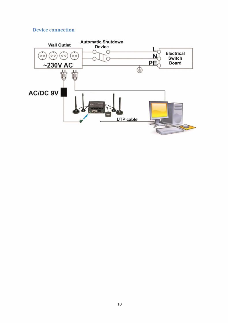
Device connection
11
1 Introduction
Thank you for purchasing a RUT955 LTE router! RUT955 is part of the RUT9xx series of compact mobile routers with high speed wireless and Ethernet
connections. This router is ideal for people who‘d like to share their internet on the go, as it is not restricted by a cumbersome
cable connection. Unrestricted, but not forgotten: the router still supports internet distribution via a broadband cable, simply plug it in to the wan port, set the router to a correct mode and you are ready to browse.
2 Specifications
2.1 Ethernet
IEEE 802.3, IEEE 802.3u standards
3 x LAN 10/100Mbps Ethernet ports
1 x WAN 10/100Mbps Ethernet port
Supports Auto MDI/MDIX
2.2 Wi-Fi
IEEE 802.11b/g/n WiFi standards
2x2 MIMO
AP and STA modes
64/128-bit WEP, WPA, WPA2, WPA&WPA2 encryption methods
2.401 – 2.495GHz Wi-Fi frequency range
20dBm max WiFi TX power
SSID stealth mode and access control based on MAC address
2.3 Hardware
High performance 560 MHz CPU with 128 Mbytes of DDR2 memory
2 pin industrial DC power socket
Attachable DIN rail adapter
4 pin industrial socket for 2/4 wire RS485
DB9 socket for full-featured RS232
USB A socket for external devices4 pin industrial socket for 2/4 wire RS485
Reset/restore to default button
2 x SMA for LTE , 2 x RP-SMA for WiFi antenna connectors
4 x Ethernet LEDs, 1 x Power LED
1 x bi-color connection status LED, 5 x connection strength LEDs
10 pin industrial socket for inputs/outputs:
- 0 - 3 V digital input
- 0 - 30 V digital galvanically isolated input
- 0 - 24 V analog input 30 V, 250 mA digital open collector output
- 40 V, 4 A SPST relay output
12
2.4 Electrical, Mechanical & Environmental
Dimensions (H x W x D) 80mm x 106mm x 46mm
Weight 250g
Power supply 100 – 240 VAC -> 9 VDC wall adapter
Input voltage range 9 – 30VDC
Power consumption < 7W
Operating temperature -40° to 75° C
Storage temperature -45° to 80° C
Operating humidity 10% to 90% Non-condensing
Storage humidity 5% to 95% Non-condensing
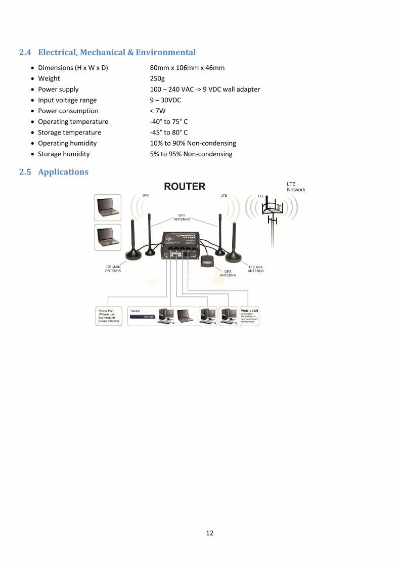
2.5 Applications

13
3 Setting up your router
3.1 Installation
After you unpack the box, follow the steps, documented below, in order to properly connect the device. For
better Wi-Fi performance, put the device in clearly visible spot, as obstacles such as walls and door hinder the signal.
1. First assemble your router by attaching the necessary antennas and inserting the SIM card.
2. To power up your router, please use the power adapter included in the box. (IMPORTANT: Using a different
power adapter can damage and void the warranty for this product.).
3. If you have a wired broadband connection you will also have to connect it to the WAN port of the router.
3.1.1 Front Panel and Back Panel
1,2,3 LAN Ethernet ports 1 LTEauxiliary antenna connector
4 WAN Ethernet port 2 GPS antenna connector
5,6,7 LAN LEDs 3 LTE main antenna connector
8 WAN LED 4 USB connector
9 RS485 connector 5,7 WiFi antenna connectors
10 Power socket 6 Reset button
11 RS232 connector
12 Inputs and outputs connector
13 Power LED
14 Connection LED
15 Signal strength LED
3.1.2 Connection status LED indication
Constant blinking (~ 2Hz) – router is turning on.
LED turned off – it has no 4G data connection
LED turned on – it has 4G data connection.
Explanation of connection status LED indication:
1. Green and red blinking alternatively ever 500 ms: no SIM or bad PIN;
2. Green, red and yellow blinking alternatively every 500 ms: connecting to GSM;
3. Red blinking every 1 sec: connected 2G, but no data session established;
4. Yellow blinking every 1 sec: connected 3G, no data session established;
5. Green blinking every 1 sec: connected 4G, no data session established;
Red lit and blinking rapidly while data is being transferred: connected 2G with data session;
Yellow lit and blinking rapidly while data is being transferred: connected 3G with data session;
Green lit and blinking rapidly while data is being transferred: connected 4G with data session;
14
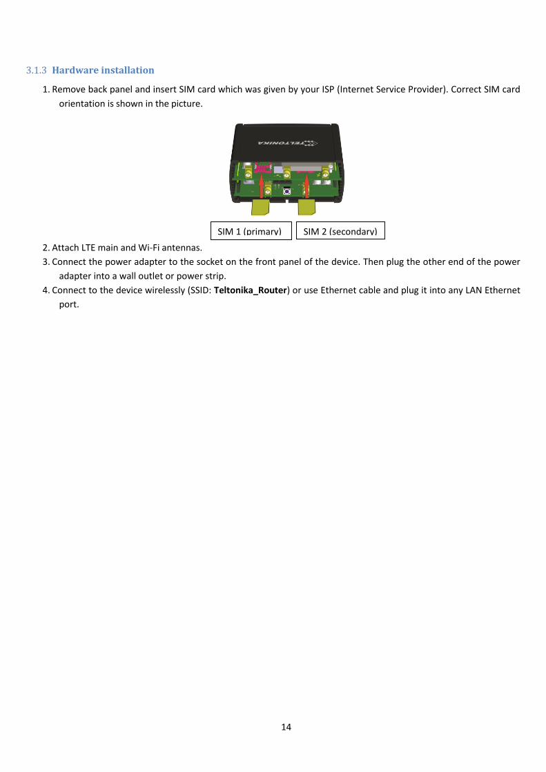
3.1.3 Hardware installation
1. Remove back panel and insert SIM card which was given by your ISP (Internet Service Provider). Correct SIM card
orientation is shown in the picture.
2. Attach LTE main and Wi-Fi antennas.
3. Connect the power adapter to the socket on the front panel of the device. Then plug the other end of the power
adapter into a wall outlet or power strip.
4. Connect to the device wirelessly (SSID: Teltonika_Router) or use Ethernet cable and plug it into any LAN Ethernet
port.
SIM 1 (primary) SIM 2 (secondary)
15
3.2 Logging in
After you’re complete with the setting up as described in the section above, you are ready to start logging into
your router and start configuring it. This example shows how to connect on Windows 7. On windows Vista: click Start ->
Control Panel -> Network and Sharing Centre -> Manage network Connections -> (Go to step 4). On Windows XP: Click
Start -> Settings -> Network Connections -> (see step 4). You wont’s see “Internet protocol version 4(TCP/IPv4)”, instead
you’ll have to select “TCP/IP Settings” and click options -> (Go to step 6)
We first must set up our network card so that it could properly communicate with the router.
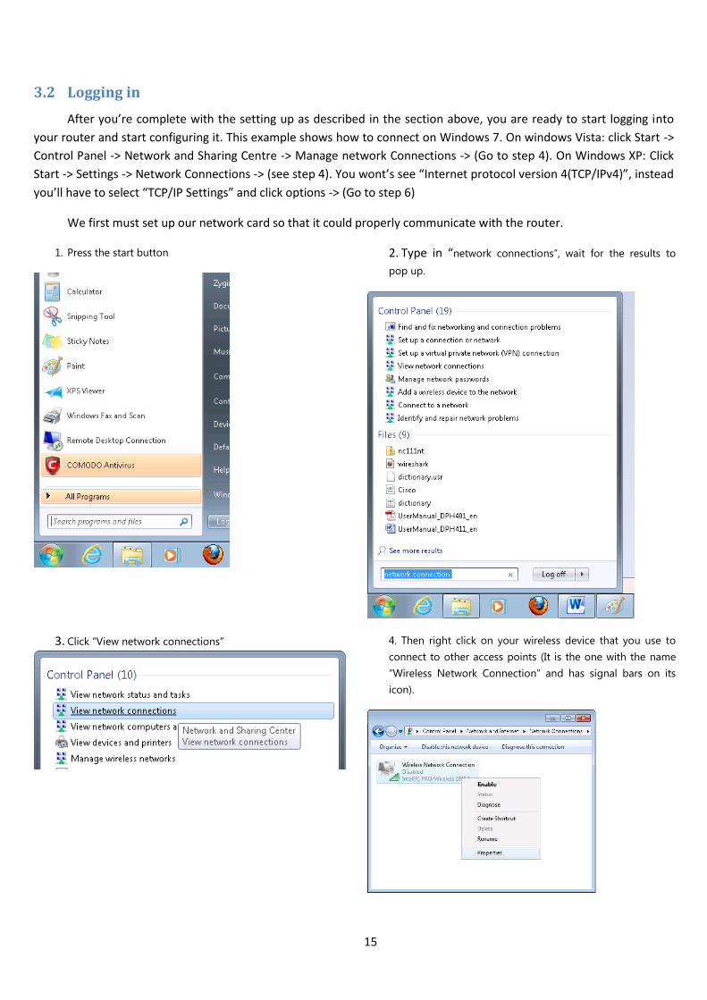
1. Press the start button
2. Type in “network connections”, wait for the results to
pop up.
3. Click “View network connections”
4. Then right click on your wireless device that you use to
connect to other access points (It is the one with the name
“Wireless Network Connection” and has signal bars on its
icon).

16
5. Select Internet Protocol Version 4 (TCP/IPv4) and then click
Properties
6. By default the router is going to have DHCP enabled,
which means that if you select “Obtain an IP address
automatically” and “Obtain DNS server address
automatically”, the router should lease you an IP and you
should be ready to login.
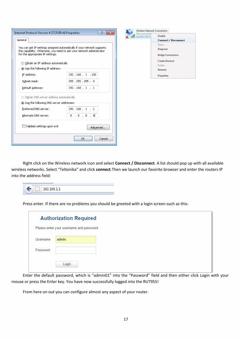
7. If you choose to configure manually here’s what you do:
First select an IP address. Due to the stock settings that your router has arrived in you can only enter an IP in the
form of 192.168.1.XXX , where XXX is a number in the range of 2-254 (192.168.1.2 , 192.168.1.254 , 192.168.1.155 and
so on… are valid; 192.168.1.0 , 192.168.1.1 , 192.168.1.255 , 192.168.1.699 and so on… are not). Next we enter the
subnet mask: this has to be “255.255.255.0”. Then we enter the default gateway: this has to be “192.168.1.1”. Finally we
enter primary and secondary DNS server IPs. One will suffice, though it is good to have a secondary one as well as it will
act as a backup if the first should fail. The DNS can be your routers IP (192.168.1.1), but it can also be some external DNS
server (like the one Google provides: 8.8.8.8).
17
Right click on the Wireless network icon and select Connect / Disconnect. A list should pop up with all available
wireless networks. Select “Teltonika” and click connect.Then we launch our favorite browser and enter the routers IP
into the address field:
Press enter. If there are no problems you should be greeted with a login screen such as this:
Enter the default password, which is “admin01” into the “Password” field and then either click Login with your
mouse or press the Enter key. You have now successfully logged into the RUT955!
From here on out you can configure almost any aspect of your router.
18
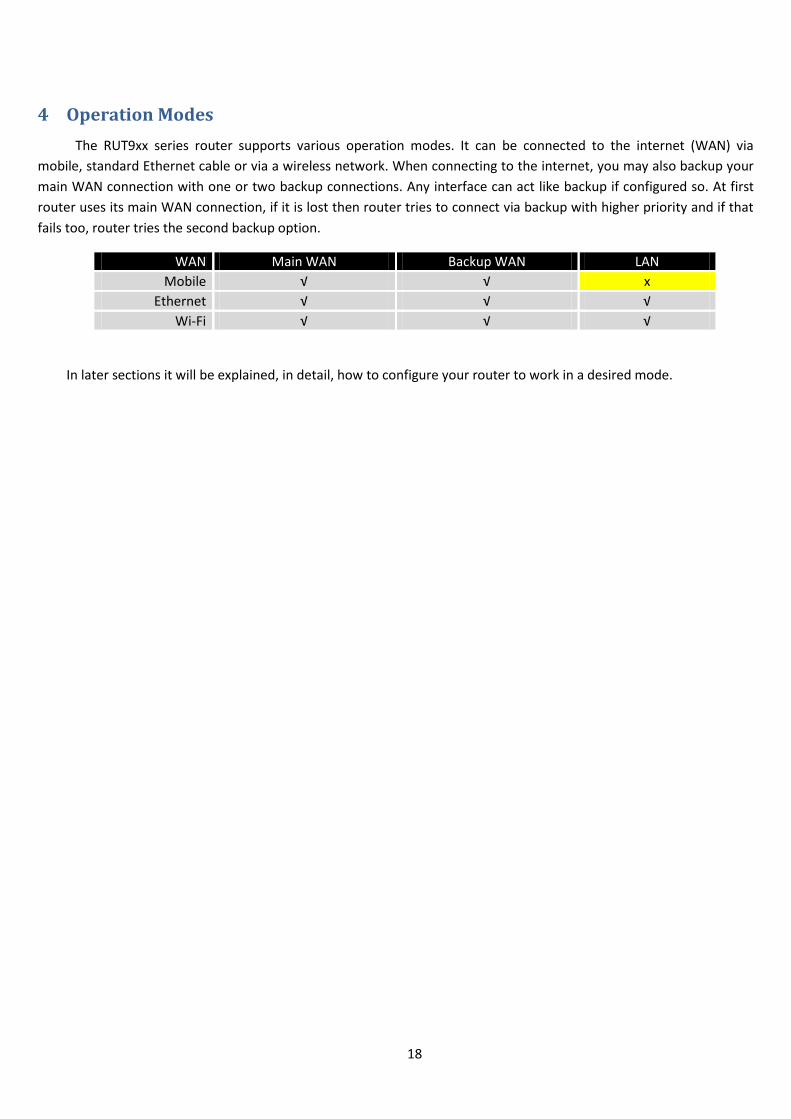
4 Operation Modes
The RUT9xx series router supports various operation modes. It can be connected to the internet (WAN) via
mobile, standard Ethernet cable or via a wireless network. When connecting to the internet, you may also backup your
main WAN connection with one or two backup connections. Any interface can act like backup if configured so. At first
router uses its main WAN connection, if it is lost then router tries to connect via backup with higher priority and if that
fails too, router tries the second backup option.
WAN Main WAN Backup WAN LAN
Mobile √ √ x
Ethernet √ √ √
Wi-Fi √ √ √
In later sections it will be explained, in detail, how to configure your router to work in a desired mode.

19
5 Powering Options
The RUT9xx router can be powered from power socket or over Ethernet port. Depending on your network
architecture you can use LAN 1 port to power the device.
RUT9xx can be powered from power socket and over Ethernet simultaneously. Power socket has higher priority
meaning that the device will draw power from power socket as long as it is available.
When RUT9xx is switching from one power source to the other it loses power for a fraction of the second and
may reboot. The device will function correctly after the reboot.
Though the device can be powered over Ethernet port it is not compliant with IEEE 802.3af-2003 standard.
Powering RUT9xx from IEEE 802.3af-2003 power supply will damage the device as it is not rated for input voltages of
PoE standard.
5.1 Powering the device from higher voltage
If you decide not to use our standard 9 VDC wall adapters and want to power the device from higher voltage (15 –
30 VDC) please make sure that you choose power supply of high quality. Some power supplies can produce voltage
peaks significantly higher than the declared output voltage, especially during connecting and disconnecting them.
While the device is designed to accept input voltage of up to 30 VDC peaks from high voltage power supplies can
harm the device. If you want to use high voltage power supplies it is recommended to also use additional safety
equipment to suppress voltage peaks from power supply.
20
6 Status
The status section contains various information, like current IP addresses of various network interfaces; the state
of the routers memory; firmware version; DHCP leases; associated wireless stations; graphs indicating load, traffic, etc.;
and much more.
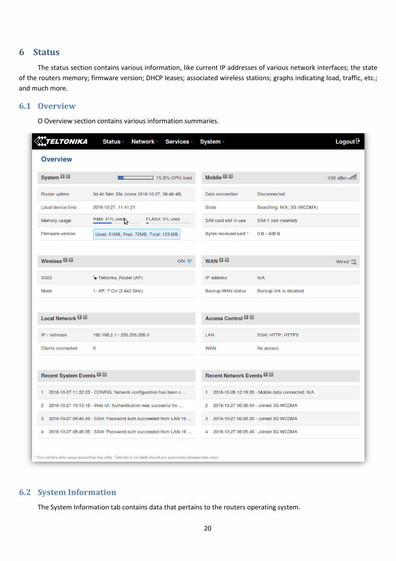
6.1 Overview
O Overview section contains various information summaries.
6.2 System Information
The System Information tab contains data that pertains to the routers operating system.

21
System explanation:
Field Name Sample value Explanation
1. Router Name RUT955 Name of the router (hostname of the routers system). Can be changed in System -> Administration.
2. Host name Teltonika-RUT955.com Indicates how router will be seen by other devices on the network. Can be changed in System -> Administration.
3. Router Model Teltonika RUT955 LTE Routers model.
4. Firmware Version
RUT9XX_R_00.02.376 Shows the version of the firmware that is currently loaded in the router. Newer versions might become available as new features are added. Use this field to decide whether you need a firmware upgrade or not.
5. Kernel Version 3.10.36 The version of the Linux kernel that is currently running on the router.
6. Local Time 2016-05-24, 11:02:39 Shows the current system time. Might differ from your computer, because the router synchronizes it's time with an NTP server.Format [year-month-day, hours:minutes:seconds].
7. Uptime 0d 0h 44m 1s (since 2016-05-24, 10:19:03)
Indicates how long it has been since the router booted up. Reboots will reset this timer to 0.Format *day’s hours minutes seconds (since year-month-day, hours: minutes: seconds)].
8. Load Average 1 min: 88%; 5 mins: 73%; 15 mins: 42%
Indicates how busy the router is. Let's examine some sample output: "1 min: 88%, 5 mins: 73%, 15 mins: 42%". The first number mean past minute and second number means that in the past minute there have been, on average, 88% processes running or waiting for a resource.
9. Temperature 34.9° C Device’s temperature
Memory explanation:
Field Name Sample Value Explanation
1. Free 84584 kB /126556 kB (66%) The amount of memory that is completely free. Should this rapidly decrease or get close to 0, it would indicate that the router is running out of memory, which could cause crashes and unexpected reboots.
22
2. Cached 14784 kB /126556 kB (11%) The size of the area of memory that is dedicated to storing frequently accessed data.
3. Buffered 5504 kB / 126556 kB (4%) The size of the area in which data is temporarily stored before moving it to another location.
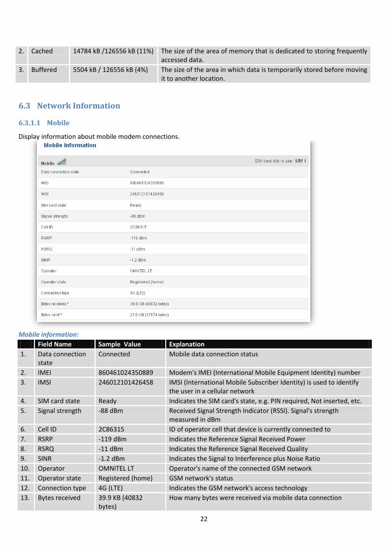
6.3 Network Information
6.3.1.1 Mobile
Display information about mobile modem connections.
Mobile information:
Field Name Sample Value Explanation
1. Data connection state
Connected Mobile data connection status
2. IMEI 860461024350889 Modem's IMEI (International Mobile Equipment Identity) number
3. IMSI 246012101426458 IMSI (International Mobile Subscriber Identity) is used to identify the user in a cellular network
4. SIM card state Ready Indicates the SIM card's state, e.g. PIN required, Not inserted, etc.
5. Signal strength -88 dBm Received Signal Strength Indicator (RSSI). Signal's strength measured in dBm
6. Cell ID 2C86315 ID of operator cell that device is currently connected to
7. RSRP -119 dBm Indicates the Reference Signal Received Power
8. RSRQ -11 dBm Indicates the Reference Signal Received Quality
9. SINR -1.2 dBm Indicates the Signal to Interference plus Noise Ratio
10. Operator OMNITEL LT Operator's name of the connected GSM network
11. Operator state Registered (home) GSM network's status
12. Connection type 4G (LTE) Indicates the GSM network's access technology
13. Bytes received 39.9 KB (40832 bytes)
How many bytes were received via mobile data connection
23
14. Bytes sent 27.0 KB (27674 bytes)
How many bytes were sent via mobile data connection
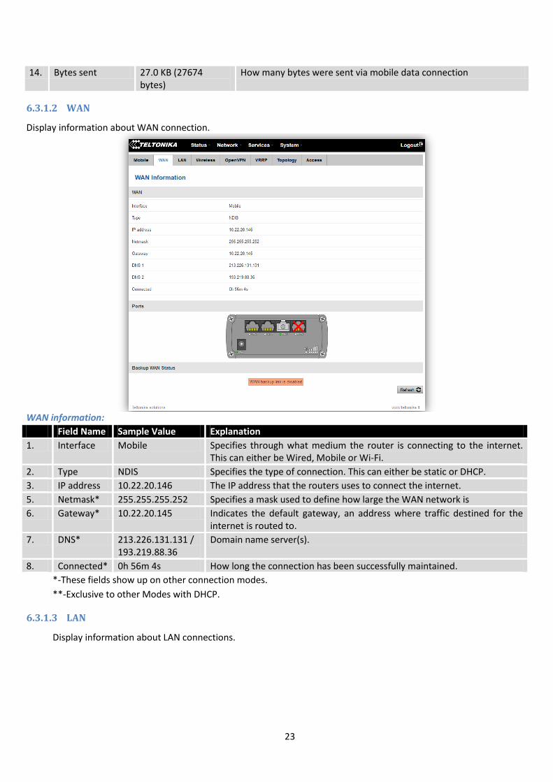
6.3.1.2 WAN
Display information about WAN connection.
WAN information:
Field Name Sample Value Explanation
1. Interface Mobile Specifies through what medium the router is connecting to the internet. This can either be Wired, Mobile or Wi-Fi.
2. Type NDIS Specifies the type of connection. This can either be static or DHCP.
3. IP address 10.22.20.146 The IP address that the routers uses to connect the internet.
5. Netmask* 255.255.255.252 Specifies a mask used to define how large the WAN network is
6. Gateway* 10.22.20.145 Indicates the default gateway, an address where traffic destined for the internet is routed to.
7. DNS* 213.226.131.131 / 193.219.88.36
Domain name server(s).
8. Connected* 0h 56m 4s How long the connection has been successfully maintained.
*-These fields show up on other connection modes.
**-Exclusive to other Modes with DHCP.
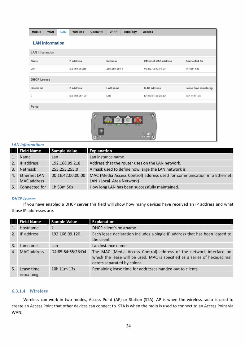
6.3.1.3 LAN
Display information about LAN connections.
24
LAN information:
Field Name Sample Value Explanation
1. Name Lan Lan instance name
2. IP address 192.168.99.218 Address that the router uses on the LAN network.
3. Netmask 255.255.255.0 A mask used to define how large the LAN network is
4. Ethernet LAN MAC address
00:1E:42:00:00:00 MAC (Media Access Control) address used for communication in a Ethernet LAN (Local Area Network)
5. Connected for 1h 53m 56s How long LAN has been successfully maintained.
DHCP Leases
If you have enabled a DHCP server this field will show how many devices have received an IP address and what
those IP addresses are.
Field Name Sample Value Explanation
1. Hostname ? DHCP client's hostname
2. IP address 192.168.99.120 Each lease declaration includes a single IP address that has been leased to the client
3. Lan name Lan Lan instance name
4. MAC address D4:85:64:65:2B:D4 The MAC (Media Access Control) address of the network interface on which the lease will be used. MAC is specified as a series of hexadecimal octets separated by colons
5. Lease time remaining
10h 11m 13s Remaining lease time for addresses handed out to clients
6.3.1.4 Wireless
Wireless can work in two modes, Access Point (AP) or Station (STA). AP is when the wireless radio is used to
create an Access Point that other devices can connect to. STA is when the radio is used to connect to an Access Point via
WAN.
25
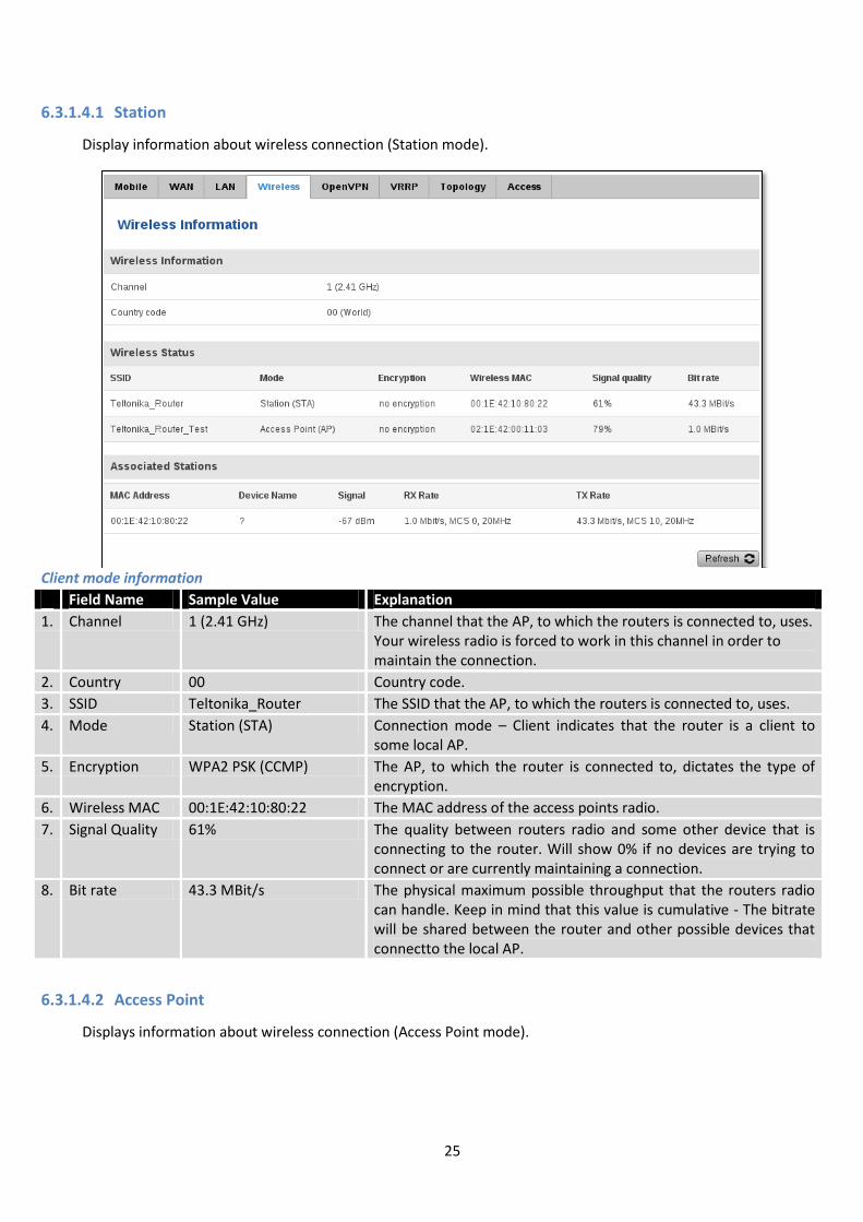
6.3.1.4.1 Station
Display information about wireless connection (Station mode).
Client mode information
Field Name Sample Value Explanation
1. Channel 1 (2.41 GHz) The channel that the AP, to which the routers is connected to, uses. Your wireless radio is forced to work in this channel in order to maintain the connection.
2. Country 00 Country code.
3. SSID Teltonika_Router The SSID that the AP, to which the routers is connected to, uses.
4. Mode Station (STA) Connection mode – Client indicates that the router is a client to some local AP.
5. Encryption WPA2 PSK (CCMP) The AP, to which the router is connected to, dictates the type of encryption.
6. Wireless MAC 00:1E:42:10:80:22 The MAC address of the access points radio.
7. Signal Quality 61% The quality between routers radio and some other device that is connecting to the router. Will show 0% if no devices are trying to connect or are currently maintaining a connection.
8. Bit rate 43.3 MBit/s The physical maximum possible throughput that the routers radio can handle. Keep in mind that this value is cumulative - The bitrate will be shared between the router and other possible devices that connectto the local AP.
6.3.1.4.2 Access Point
Displays information about wireless connection (Access Point mode).
26
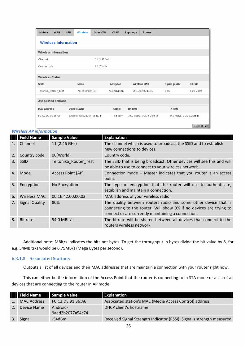
Wireless AP information
Field Name Sample Value Explanation
1. Channel 11 (2.46 GHz) The channel which is used to broadcast the SSID and to establish new connections to devices.
2. Country code 00(World) Country code.
3. SSID Teltonika_Router_Test The SSID that is being broadcast. Other devices will see this and will be able to use to connect to your wireless network.
4. Mode Access Point (AP) Connection mode – Master indicates that you router is an access point.
5. Encryption No Encryption The type of encryption that the router will use to authenticate, establish and maintain a connection.
6. Wireless MAC 00:1E:42:00:00:03 MAC address of your wireless radio.
7. Signal Quality 80% The quality between routers radio and some other device that is connecting to the router. Will show 0% if no devices are trying to connect or are currently maintaining a connection.
8. Bit rate 54.0 MBit/s The bitrate will be shared between all devices that connect to the routers wireless network.
Additional note: MBit/s indicates the bits not bytes. To get the throughput in bytes divide the bit value by 8, for
e.g. 54MBits/s would be 6.75MB/s (Mega Bytes per second).
6.3.1.5 Associated Stations
Outputs a list of all devices and their MAC addresses that are maintain a connection with your router right now.
This can either be the information of the Access Point that the router is connecting to in STA mode or a list of all
devices that are connecting to the router in AP mode:
Field Name Sample Value Explanation
1. MAC Address FC:C2:DE:91:36:A6 Associated station's MAC (Media Access Control) address
2. Device Name Android-9aed2b2077a54c74
DHCP client's hostname
3. Signal -54dBm Received Signal Strength Indicator (RSSI). Signal's strength measured
27
in dBm
4. RX Rate 24.0Mbit/s, MCS 0, 20MHz
The rate at which packets are received from associated station
5. TX Rate 54.0Mbit/s, MCS 0, 20MHz
The rate at which packets are sent to associated station
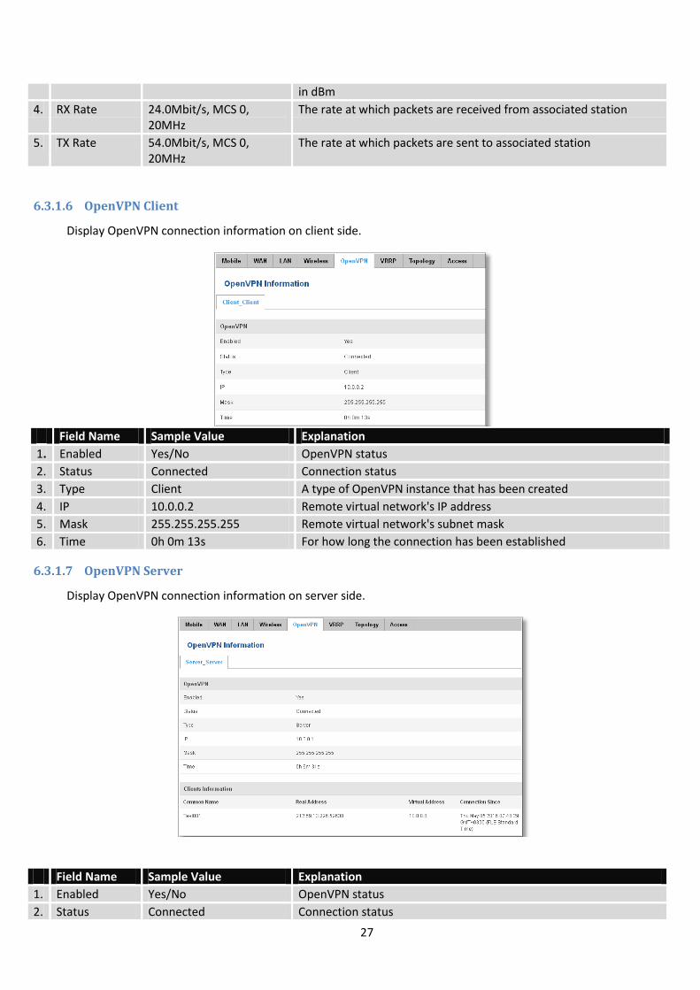
6.3.1.6 OpenVPN Client
Display OpenVPN connection information on client side.
Field Name Sample Value Explanation
1. Enabled Yes/No OpenVPN status
2. Status Connected Connection status
3. Type Client A type of OpenVPN instance that has been created
4. IP 10.0.0.2 Remote virtual network's IP address
5. Mask 255.255.255.255 Remote virtual network's subnet mask
6. Time 0h 0m 13s For how long the connection has been established
6.3.1.7 OpenVPN Server
Display OpenVPN connection information on server side.
Field Name Sample Value Explanation
1. Enabled Yes/No OpenVPN status
2. Status Connected Connection status
28
2. Type Server A type of OpenVPN instance that has been created
3. IP 10.0.0.1 Remote virtual network's IP address
4. Mask 255.255.255.255 Remote virtual network's subnet mask
5. Time 0h 3m 24s For how long the connection has been established
6.3.1.8 Clients information
It will show information, when router is configured as OpenVPN TLS server.
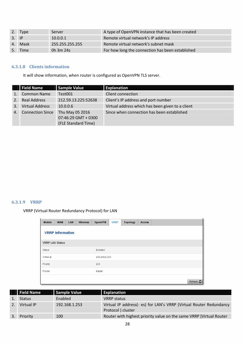
6.3.1.9 VRRP
VRRP (Virtual Router Redundancy Protocol) for LAN
Field Name Sample Value Explanation
1. Status Enabled VRRP status
2. Virtual IP 192.168.1.253 Virtual IP address(- es) for LAN’s VRRP (Virtual Router Redundancy Protocol ) cluster
3. Priority 100 Router with highest priority value on the same VRRP (Virtual Router
Field Name Sample Value Explanation
1. Common Name Test001 Client connection
2. Real Address 212.59.13.225:52638 Client’s IP address and port number
3. Virtual Address 10.0.0.6 Virtual address which has been given to a client
4. Connection Since Thu May 05 2016 07:46:29 GMT + 0300 (FLE Standard Time)
Since when connection has been established
29
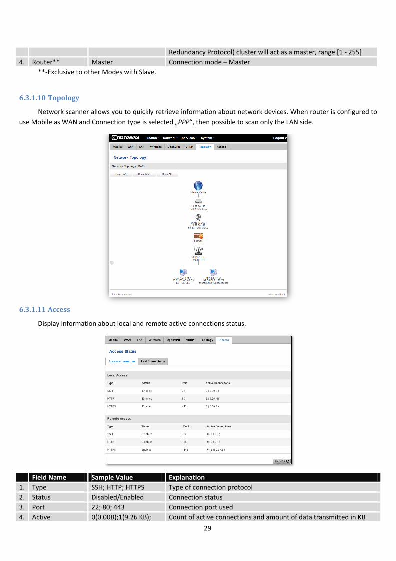
Redundancy Protocol) cluster will act as a master, range [1 - 255]
4. Router** Master Connection mode – Master
**-Exclusive to other Modes with Slave.
6.3.1.10 Topology
Network scanner allows you to quickly retrieve information about network devices. When router is configured to
use Mobile as WAN and Connection type is selected „PPP“, then possible to scan only the LAN side.
6.3.1.11 Access
Display information about local and remote active connections status.
Field Name Sample Value Explanation
1. Type SSH; HTTP; HTTPS Type of connection protocol
2. Status Disabled/Enabled Connection status
3. Port 22; 80; 443 Connection port used
4. Active 0(0.00B);1(9.26 KB); Count of active connections and amount of data transmitted in KB
30
Connections 6(558.12 KB)
**-Exclusive to other Modes with Slave.
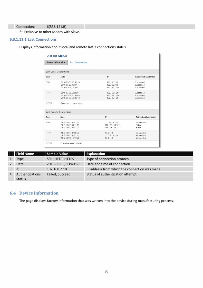
6.3.1.11.1 Last Connections
Displays information about local and remote last 3 connections status
Field Name Sample Value Explanation
1. Type SSH; HTTP; HTTPS Type of connection protocol
2. Date 2016-03-03, 13:40:59 Date and time of connection
3. IP 192.168.2.10 IP address from which the connection was made
4. Authentications Status
Failed; Succeed Status of authentication attempt
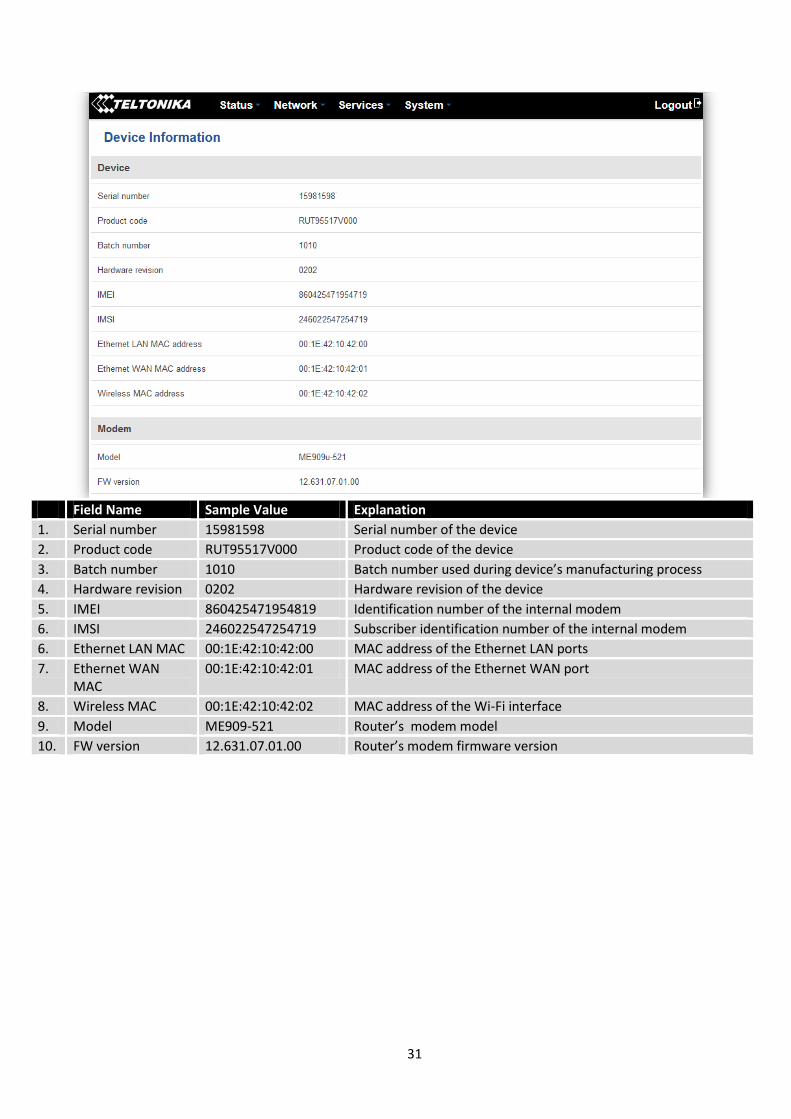
6.4 Device information
The page displays factory information that was written into the device during manufacturing process.
31
Field Name Sample Value Explanation
1. Serial number 15981598 Serial number of the device
2. Product code RUT95517V000 Product code of the device
3. Batch number 1010 Batch number used during device’s manufacturing process
4. Hardware revision 0202 Hardware revision of the device
5. IMEI 860425471954819 Identification number of the internal modem
6. IMSI 246022547254719 Subscriber identification number of the internal modem
6. Ethernet LAN MAC 00:1E:42:10:42:00 MAC address of the Ethernet LAN ports
7. Ethernet WAN MAC
00:1E:42:10:42:01 MAC address of the Ethernet WAN port
8. Wireless MAC 00:1E:42:10:42:02 MAC address of the Wi-Fi interface
9. Model ME909-521 Router’s modem model
10. FW version 12.631.07.01.00 Router’s modem firmware version
32
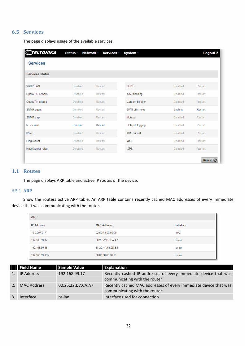
6.5 Services
The page displays usage of the available services.
1.1 Routes
The page displays ARP table and active IP routes of the device.
6.5.1 ARP
Show the routers active ARP table. An ARP table contains recently cached MAC addresses of every immediate
device that was communicating with the router.
Field Name Sample Value Explanation
1. IP Address 192.168.99.17 Recently cashed IP addresses of every immediate device that was communicating with the router
2. MAC Address 00:25:22:D7:CA:A7 Recently cached MAC addresses of every immediate device that was communicating with the router
3. Interface br-lan Interface used for connection
33
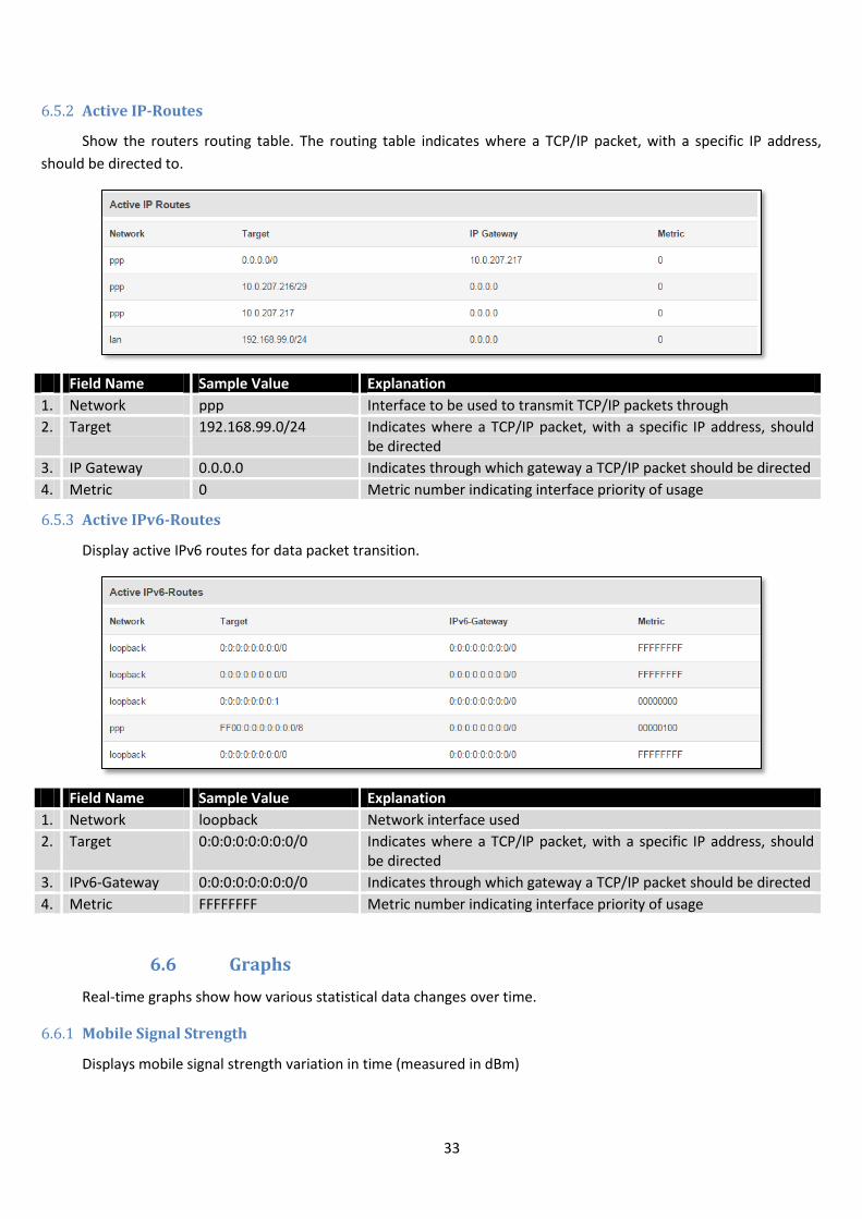
6.5.2 Active IP-Routes
Show the routers routing table. The routing table indicates where a TCP/IP packet, with a specific IP address,
should be directed to.
Field Name Sample Value Explanation
1. Network ppp Interface to be used to transmit TCP/IP packets through
2. Target 192.168.99.0/24 Indicates where a TCP/IP packet, with a specific IP address, should be directed
3. IP Gateway 0.0.0.0 Indicates through which gateway a TCP/IP packet should be directed
4. Metric 0 Metric number indicating interface priority of usage
6.5.3 Active IPv6-Routes
Display active IPv6 routes for data packet transition.
Field Name Sample Value Explanation
1. Network loopback Network interface used
2. Target 0:0:0:0:0:0:0:0/0 Indicates where a TCP/IP packet, with a specific IP address, should be directed
3. IPv6-Gateway 0:0:0:0:0:0:0:0/0 Indicates through which gateway a TCP/IP packet should be directed
4. Metric FFFFFFFF Metric number indicating interface priority of usage
6.6 Graphs
Real-time graphs show how various statistical data changes over time.
6.6.1 Mobile Signal Strength
Displays mobile signal strength variation in time (measured in dBm)

34
Field Name Sample Value Explanation
1. Connection type 3G (WCDMA) Type of mobile connection used
2. Signal -72 dBm Current signal strength value
3. Average -72.0 dBm Average signal strength value
4. Peak -72 dBm Peak signal strength value
6.6.2 Realtime Load
This tri-graph illustrates average CPU load values in real time. The graph consists out of three color coded graphs,
each one corresponding to the average CPU load over 1 (red), 5 (orange) and 15 (yellow) most recent minutes.
Field Name Sample Value Explanation
1. 1/5/15 Minutes Load
0.83 Time interval for load averaging, colour of the diagram
2. Average 0.86 Average CPU load value over time interval (1/5/15 Minute)
3. Peak 1.50 Peak CPU load value of the time interval
35
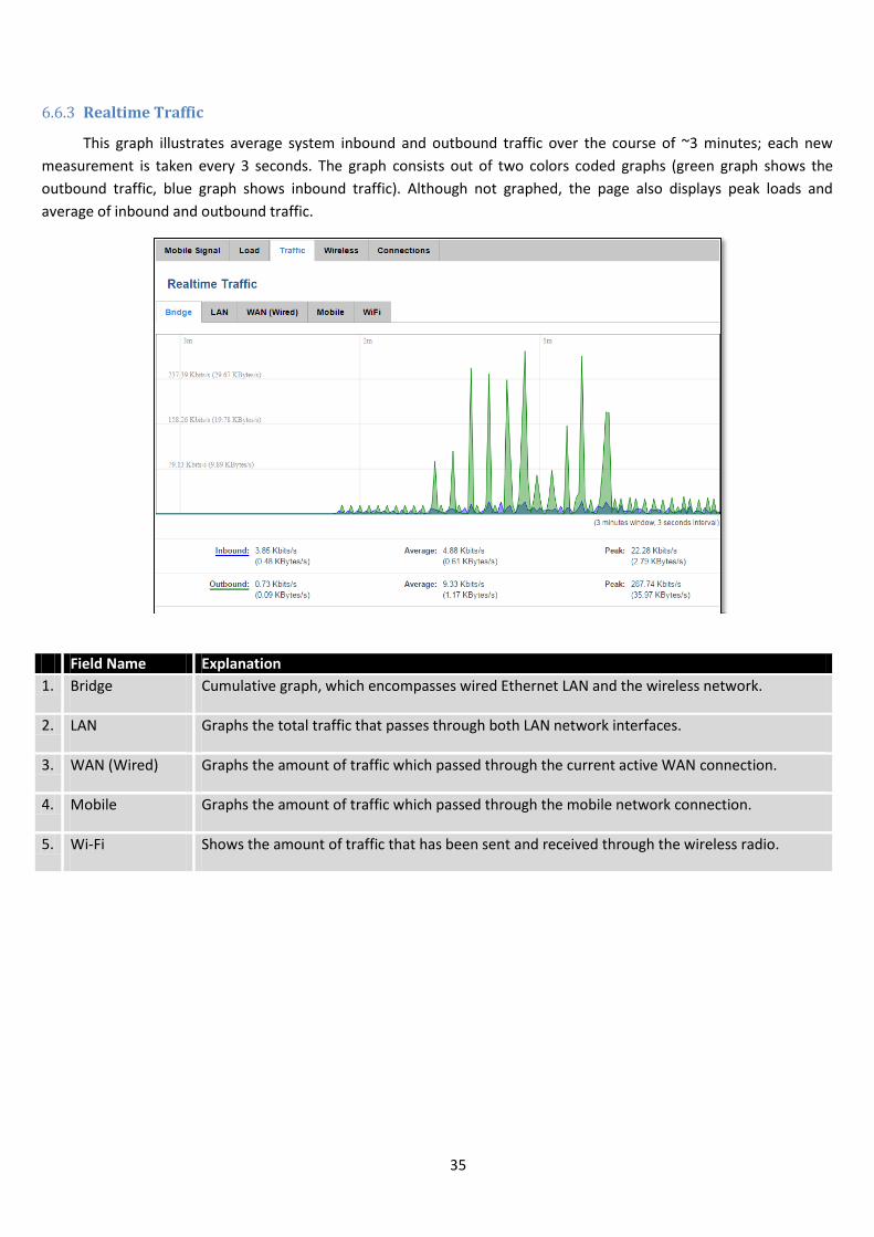
6.6.3 Realtime Traffic
This graph illustrates average system inbound and outbound traffic over the course of ~3 minutes; each new
measurement is taken every 3 seconds. The graph consists out of two colors coded graphs (green graph shows the
outbound traffic, blue graph shows inbound traffic). Although not graphed, the page also displays peak loads and
average of inbound and outbound traffic.
Field Name Explanation
1. Bridge Cumulative graph, which encompasses wired Ethernet LAN and the wireless network.
2. LAN Graphs the total traffic that passes through both LAN network interfaces.
3. WAN (Wired) Graphs the amount of traffic which passed through the current active WAN connection.
4. Mobile Graphs the amount of traffic which passed through the mobile network connection.
5. Wi-Fi Shows the amount of traffic that has been sent and received through the wireless radio.
36
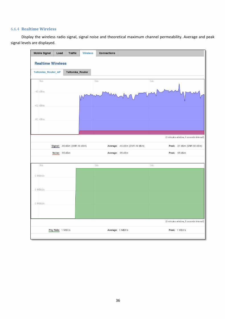
6.6.4 Realtime Wireless
Display the wireless radio signal, signal noise and theoretical maximum channel permeability. Average and peak
signal levels are displayed.

37
6.6.5 Realtime Connections
Displays currently active network connections with the information about network, protocol, source and
destination addresses, transfer speed.
38
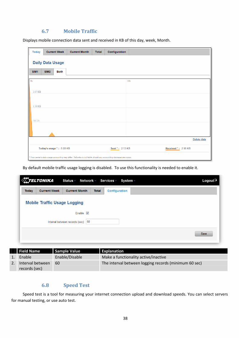
6.7 Mobile Traffic
Displays mobile connection data sent and received in KB of this day, week, Month.
By default mobile traffic usage logging is disabled. To use this functionality is needed to enable it.
Field Name Sample Value Explanation
1. Enable Enable/Disable Make a functionality active/inactive
2. Interval between records (sec)
60 The interval between logging records (minimum 60 sec)
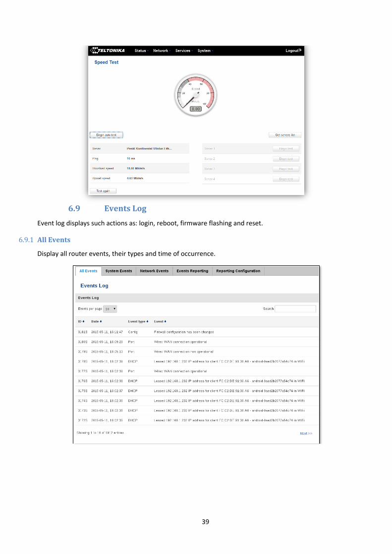
6.8 Speed Test
Speed test is a tool for measuring your internet connection upload and download speeds. You can select servers
for manual testing, or use auto test.
39
6.9 Events Log
Event log displays such actions as: login, reboot, firmware flashing and reset.
6.9.1 All Events
Display all router events, their types and time of occurrence.
40
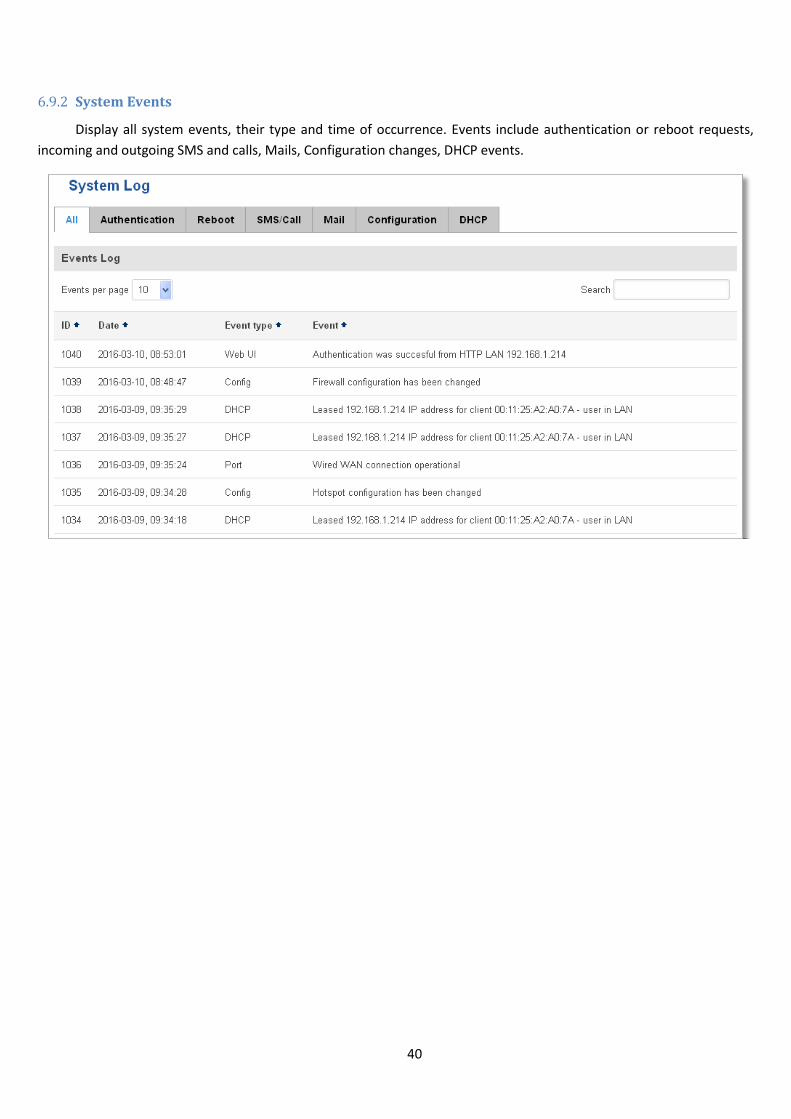
6.9.2 System Events
Display all system events, their type and time of occurrence. Events include authentication or reboot requests,
incoming and outgoing SMS and calls, Mails, Configuration changes, DHCP events.
41
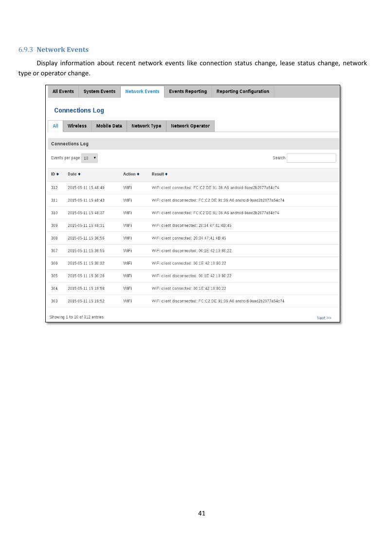
6.9.3 Network Events
Display information about recent network events like connection status change, lease status change, network
type or operator change.
42
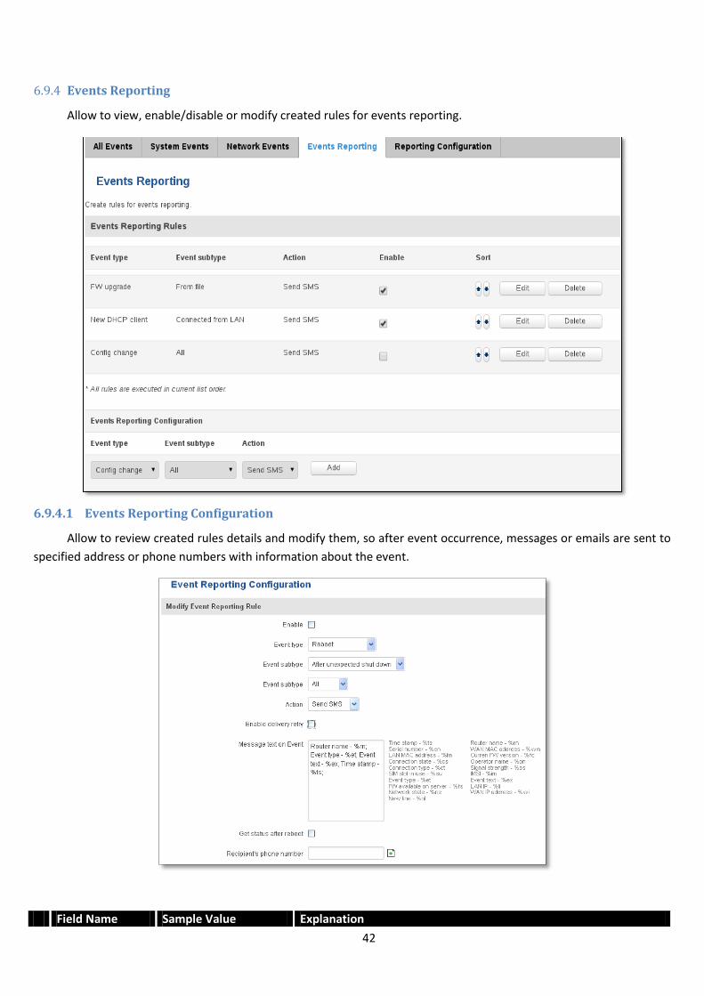
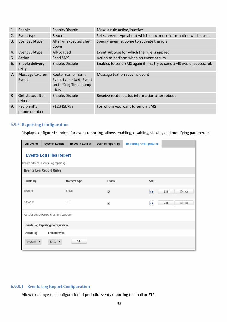
6.9.4 Events Reporting
Allow to view, enable/disable or modify created rules for events reporting.
6.9.4.1 Events Reporting Configuration
Allow to review created rules details and modify them, so after event occurrence, messages or emails are sent to
specified address or phone numbers with information about the event.
Field Name Sample Value Explanation
43
1. Enable Enable/Disable Make a rule active/inactive
2. Event type Reboot Select event type about which occurrence information will be sent
3. Event subtype After unexpected shut down
Specify event subtype to activate the rule
4. Event subtype All/Loaded Event subtype for which the rule is applied
5. Action Send SMS Action to perform when an event occurs
6. Enable delivery retry
Enable/Disable Enables to send SMS again if first try to send SMS was unsuccessful.
7. Message text on Event
Router name - %rn; Event type - %et; Event text - %ex; Time stamp - %ts;
Message text on specific event
8 Get status after reboot
Enable/Disable Receive router status information after reboot
9. Recipient‘s phone number
+123456789 For whom you want to send a SMS
6.9.5 Reporting Configuration
Displays configured services for event reporting, allows enabling, disabling, viewing and modifying parameters.
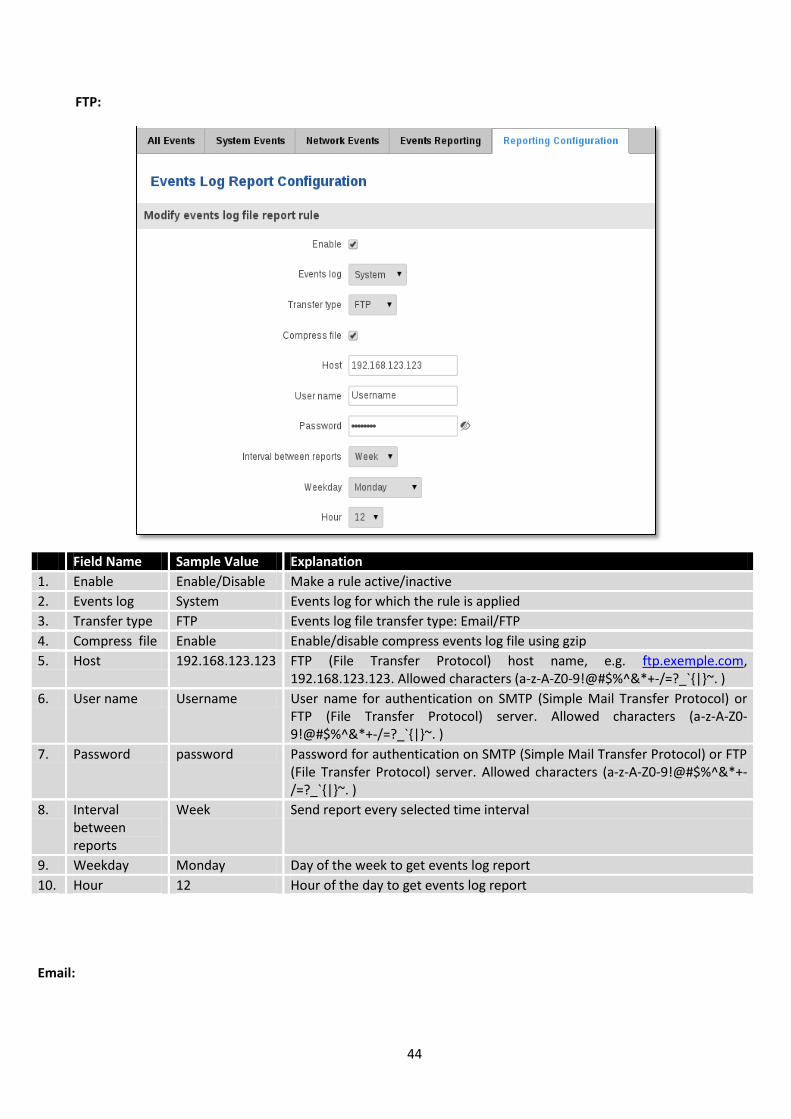
6.9.5.1 Events Log Report Configuration
Allow to change the configuration of periodic events reporting to email or FTP.
44
FTP:
Field Name Sample Value Explanation
1. Enable Enable/Disable Make a rule active/inactive
2. Events log System Events log for which the rule is applied
3. Transfer type FTP Events log file transfer type: Email/FTP
4. Compress file Enable Enable/disable compress events log file using gzip
5. Host 192.168.123.123 FTP (File Transfer Protocol) host name, e.g. ftp.exemple.com, 192.168.123.123. Allowed characters (a-z-A-Z0-9!@#$%^&*+-/=?_`|~. )
6. User name Username User name for authentication on SMTP (Simple Mail Transfer Protocol) or FTP (File Transfer Protocol) server. Allowed characters (a-z-A-Z0-9!@#$%^&*+-/=?_`|~. )
7. Password password Password for authentication on SMTP (Simple Mail Transfer Protocol) or FTP (File Transfer Protocol) server. Allowed characters (a-z-A-Z0-9!@#$%^&*+-/=?_`|~. )
8. Interval between reports
Week Send report every selected time interval
9. Weekday Monday Day of the week to get events log report
10. Hour 12 Hour of the day to get events log report
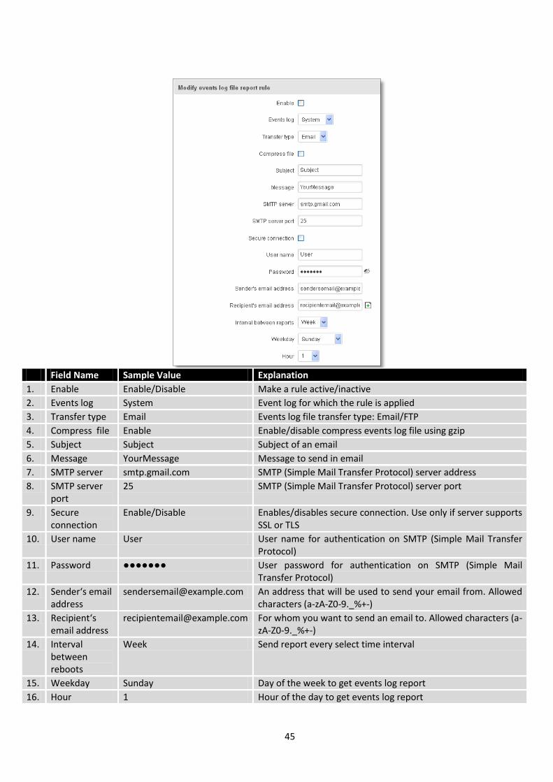
Email:
45
Field Name Sample Value Explanation
1. Enable Enable/Disable Make a rule active/inactive
2. Events log System Event log for which the rule is applied
3. Transfer type Email Events log file transfer type: Email/FTP
4. Compress file Enable Enable/disable compress events log file using gzip
5. Subject Subject Subject of an email
6. Message YourMessage Message to send in email
7. SMTP server smtp.gmail.com SMTP (Simple Mail Transfer Protocol) server address
8. SMTP server port
25 SMTP (Simple Mail Transfer Protocol) server port
9. Secure connection
Enable/Disable Enables/disables secure connection. Use only if server supports SSL or TLS
10. User name User User name for authentication on SMTP (Simple Mail Transfer Protocol)
11. Password User password for authentication on SMTP (Simple Mail Transfer Protocol)
12. Sender‘s email address
[email protected] An address that will be used to send your email from. Allowed characters (a-zA-Z0-9._%+-)
13. Recipient‘s email address
[email protected] For whom you want to send an email to. Allowed characters (a-zA-Z0-9._%+-)
14. Interval between reboots
Week Send report every select time interval
15. Weekday Sunday Day of the week to get events log report
16. Hour 1 Hour of the day to get events log report
46
7 Network
7.1 Mobile
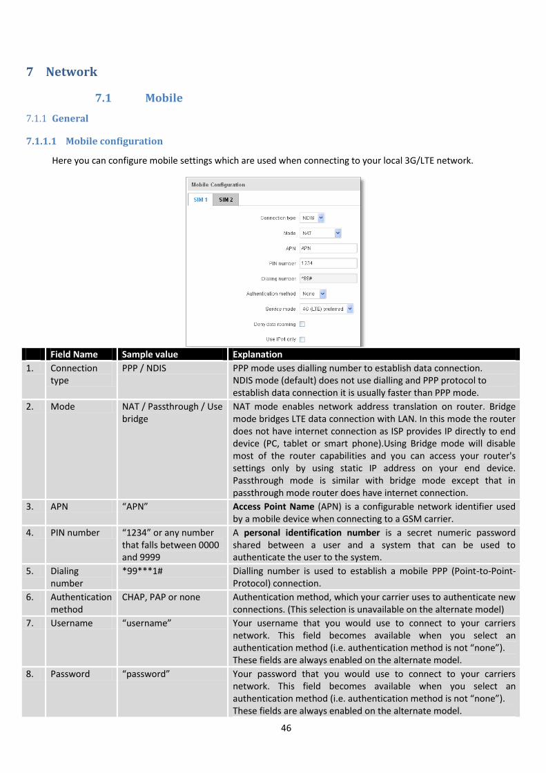
7.1.1 General
7.1.1.1 Mobile configuration
Here you can configure mobile settings which are used when connecting to your local 3G/LTE network.
Field Name Sample value Explanation
1. Connection type
PPP / NDIS PPP mode uses dialling number to establish data connection. NDIS mode (default) does not use dialling and PPP protocol to establish data connection it is usually faster than PPP mode.
2. Mode NAT / Passthrough / Use bridge
NAT mode enables network address translation on router. Bridge mode bridges LTE data connection with LAN. In this mode the router does not have internet connection as ISP provides IP directly to end device (PC, tablet or smart phone).Using Bridge mode will disable most of the router capabilities and you can access your router's settings only by using static IP address on your end device. Passthrough mode is similar with bridge mode except that in passthrough mode router does have internet connection.
3. APN “APN” Access Point Name (APN) is a configurable network identifier used by a mobile device when connecting to a GSM carrier.
4. PIN number “1234” or any number that falls between 0000 and 9999
A personal identification number is a secret numeric password shared between a user and a system that can be used to authenticate the user to the system.
5. Dialing number
*99***1# Dialling number is used to establish a mobile PPP (Point-to-Point-Protocol) connection.
6. Authentication method
CHAP, PAP or none Authentication method, which your carrier uses to authenticate new connections. (This selection is unavailable on the alternate model)
7. Username “username” Your username that you would use to connect to your carriers network. This field becomes available when you select an authentication method (i.e. authentication method is not “none”). These fields are always enabled on the alternate model.
8. Password “password” Your password that you would use to connect to your carriers network. This field becomes available when you select an authentication method (i.e. authentication method is not “none”). These fields are always enabled on the alternate model.
47
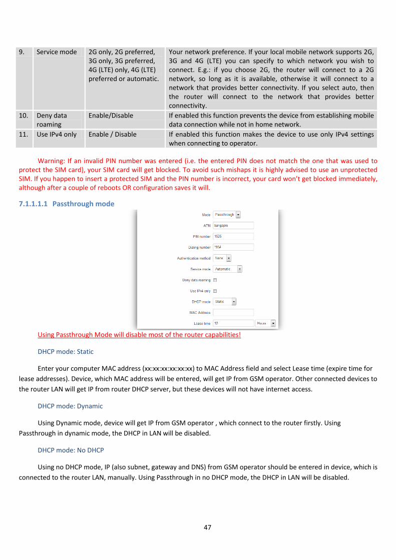
9. Service mode 2G only, 2G preferred, 3G only, 3G preferred, 4G (LTE) only, 4G (LTE) preferred or automatic.
Your network preference. If your local mobile network supports 2G, 3G and 4G (LTE) you can specify to which network you wish to connect. E.g.: if you choose 2G, the router will connect to a 2G network, so long as it is available, otherwise it will connect to a network that provides better connectivity. If you select auto, then the router will connect to the network that provides better connectivity.
10. Deny data roaming
Enable/Disable If enabled this function prevents the device from establishing mobile data connection while not in home network.
11. Use IPv4 only Enable / Disable If enabled this function makes the device to use only IPv4 settings when connecting to operator.
Warning: If an invalid PIN number was entered (i.e. the entered PIN does not match the one that was used to protect the SIM card), your SIM card will get blocked. To avoid such mishaps it is highly advised to use an unprotected SIM. If you happen to insert a protected SIM and the PIN number is incorrect, your card won’t get blocked immediately, although after a couple of reboots OR configuration saves it will.
7.1.1.1.1 Passthrough mode
Using Passthrough Mode will disable most of the router capabilities!
DHCP mode: Static
Enter your computer MAC address (xx:xx:xx:xx:xx:xx) to MAC Address field and select Lease time (expire time for
lease addresses). Device, which MAC address will be entered, will get IP from GSM operator. Other connected devices to
the router LAN will get IP from router DHCP server, but these devices will not have internet access.
DHCP mode: Dynamic
Using Dynamic mode, device will get IP from GSM operator , which connect to the router firstly. Using
Passthrough in dynamic mode, the DHCP in LAN will be disabled.
DHCP mode: No DHCP
Using no DHCP mode, IP (also subnet, gateway and DNS) from GSM operator should be entered in device, which is
connected to the router LAN, manually. Using Passthrough in no DHCP mode, the DHCP in LAN will be disabled.
48
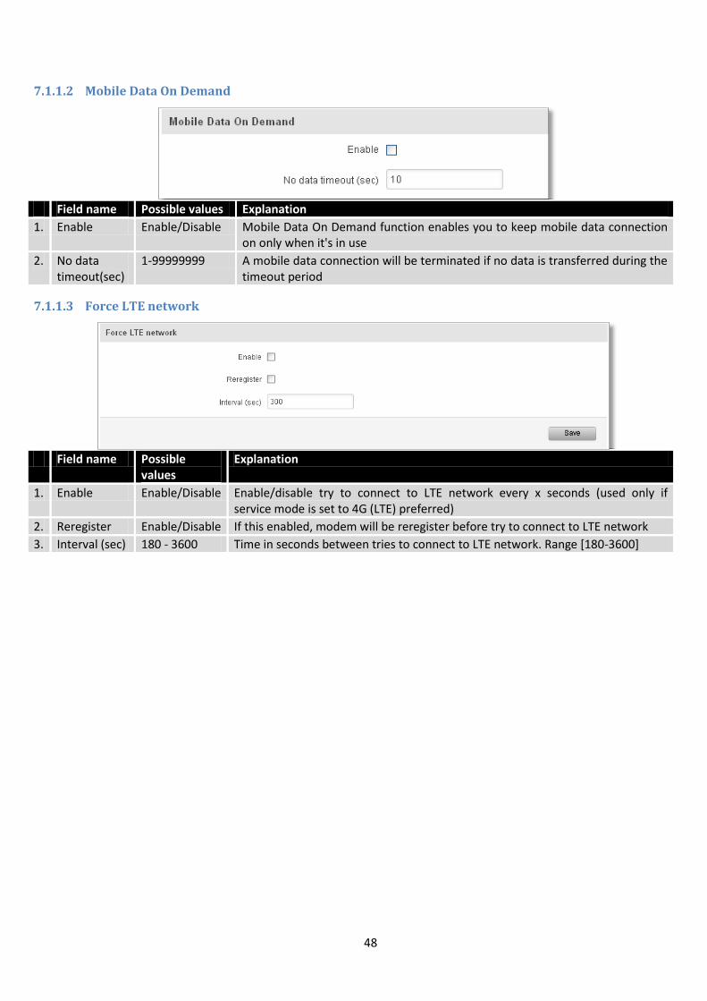
7.1.1.2 Mobile Data On Demand
Field name Possible values Explanation
1. Enable Enable/Disable Mobile Data On Demand function enables you to keep mobile data connection on only when it's in use
2. No data timeout(sec)
1-99999999 A mobile data connection will be terminated if no data is transferred during the timeout period
7.1.1.3 Force LTE network
Field name Possible
values Explanation
1. Enable Enable/Disable Enable/disable try to connect to LTE network every x seconds (used only if service mode is set to 4G (LTE) preferred)
2. Reregister Enable/Disable If this enabled, modem will be reregister before try to connect to LTE network
3. Interval (sec) 180 - 3600 Time in seconds between tries to connect to LTE network. Range [180-3600]
49
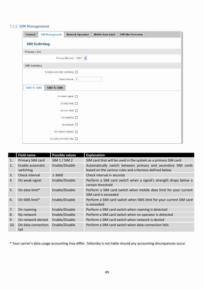
7.1.2 SIM Management
Field name Possible values Explanation
1. Primary SIM card SIM 1 / SIM 2 SIM card that will be used in the system as a primary SIM card
2. Enable automatic switching
Enable/Disable Automatically switch between primary and secondary SIM cards based on the various rules and criterions defined below
3. Check interval 1-3600 Check interval in seconds
4. On weak signal Enable/Disable Perform a SIM card switch when a signal's strength drops below a certain threshold
5. On data limit* Enable/Disable Perform a SIM card switch when mobile data limit for your current SIM card is exceeded
6. On SMS limit* Enable/Disable Perform a SIM card switch when SMS limit for your current SIM card is exceeded
7. On roaming Enable/Disable Perform a SIM card switch when roaming is detected
8. No network Enable/Disable Perform a SIM card switch when no operator is detected
9. On network denied Enable/Disable Perform a SIM card switch when network is denied
10. On data connection fail
Enable/Disable Perform a SIM card switch when data connection fails
* Your carrier's data usage accounting may differ. Teltonika is not liable should any accounting discrepancies occur.

50
7.1.3 Network Operators
7.1.3.1 Network Operators
This function lets you Scan, Select and enter manual Network Operator to which router should connect. Function
will provide great utility when router is in Roaming conditions. Operator is selected only for the active SIM card. In order
to specify operator for the other SIM card it must first be selected as primary SIM in “SIM Management”.
Note: after clicking Scan for operators’ button- You will lose current mobile connection! For changing network operator
status have to be available. There is manual connection to network operator, you have to fill numeric name, and it’s
have to be available.
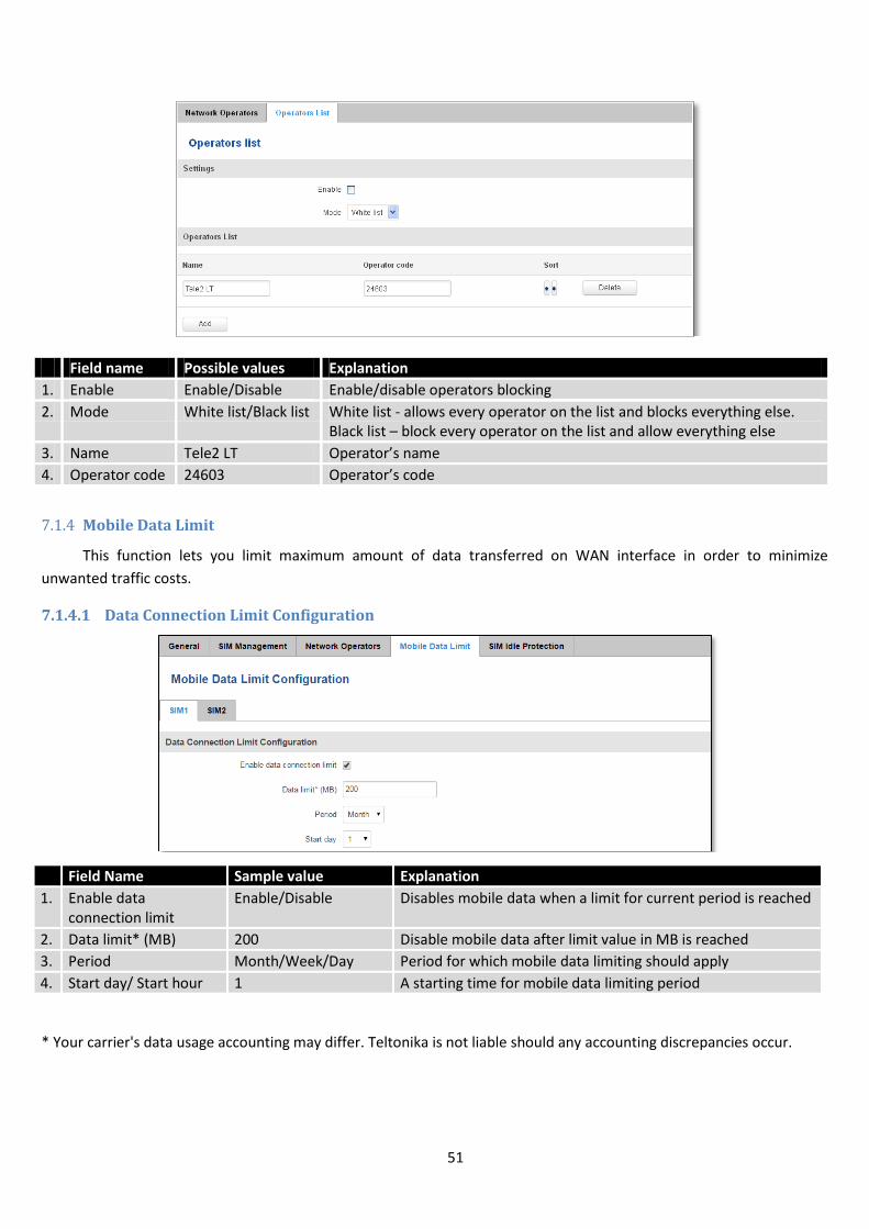
7.1.3.2 Operator List
This function lets to create white list/black list based on operator’s code.
Field Name Sample Value Explanation
1. SIM card in use SIM 1 / SIM 2 Shows current SIM card’s in use
2. Current operator OMNITEL LT Operator's name of the connected GSM network
51
Field name Possible values Explanation
1. Enable Enable/Disable Enable/disable operators blocking
2. Mode White list/Black list White list - allows every operator on the list and blocks everything else. Black list – block every operator on the list and allow everything else
3. Name Tele2 LT Operator’s name
4. Operator code 24603 Operator’s code
7.1.4 Mobile Data Limit
This function lets you limit maximum amount of data transferred on WAN interface in order to minimize
unwanted traffic costs.
7.1.4.1 Data Connection Limit Configuration
* Your carrier's data usage accounting may differ. Teltonika is not liable should any accounting discrepancies occur.
Field Name Sample value Explanation
1. Enable data connection limit
Enable/Disable Disables mobile data when a limit for current period is reached
2. Data limit* (MB) 200 Disable mobile data after limit value in MB is reached
3. Period Month/Week/Day Period for which mobile data limiting should apply
4. Start day/ Start hour 1 A starting time for mobile data limiting period
52
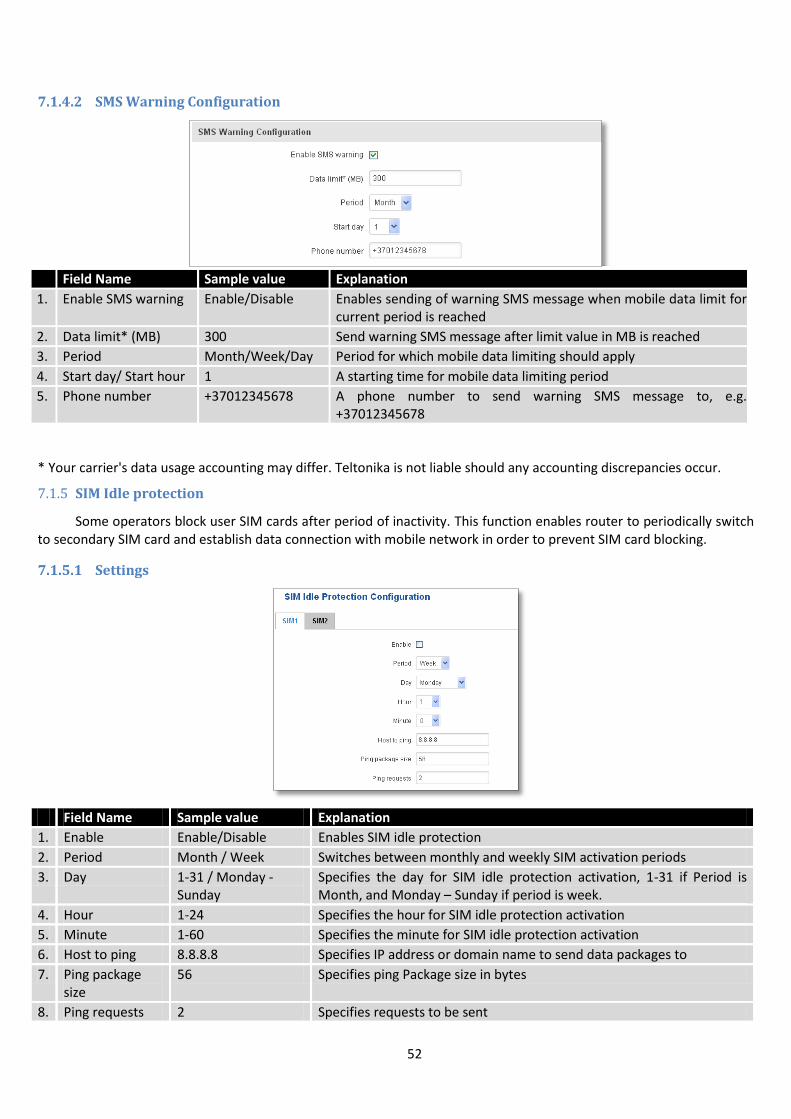
7.1.4.2 SMS Warning Configuration
* Your carrier's data usage accounting may differ. Teltonika is not liable should any accounting discrepancies occur.
7.1.5 SIM Idle protection
Some operators block user SIM cards after period of inactivity. This function enables router to periodically switch to secondary SIM card and establish data connection with mobile network in order to prevent SIM card blocking.
7.1.5.1 Settings
Field Name Sample value Explanation
1. Enable Enable/Disable Enables SIM idle protection
2. Period Month / Week Switches between monthly and weekly SIM activation periods
3. Day 1-31 / Monday - Sunday
Specifies the day for SIM idle protection activation, 1-31 if Period is Month, and Monday – Sunday if period is week.
4. Hour 1-24 Specifies the hour for SIM idle protection activation
5. Minute 1-60 Specifies the minute for SIM idle protection activation
6. Host to ping 8.8.8.8 Specifies IP address or domain name to send data packages to
7. Ping package size
56 Specifies ping Package size in bytes
8. Ping requests 2 Specifies requests to be sent
Field Name Sample value Explanation
1. Enable SMS warning Enable/Disable Enables sending of warning SMS message when mobile data limit for current period is reached
2. Data limit* (MB) 300 Send warning SMS message after limit value in MB is reached
3. Period Month/Week/Day Period for which mobile data limiting should apply
4. Start day/ Start hour 1 A starting time for mobile data limiting period
5. Phone number +37012345678 A phone number to send warning SMS message to, e.g. +37012345678
53
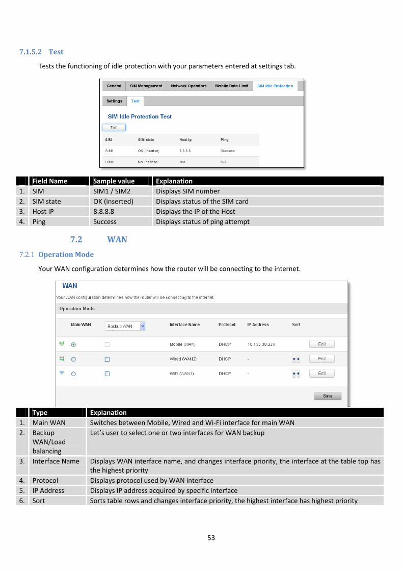
7.1.5.2 Test
Tests the functioning of idle protection with your parameters entered at settings tab.
Field Name Sample value Explanation
1. SIM SIM1 / SIM2 Displays SIM number
2. SIM state OK (inserted) Displays status of the SIM card
3. Host IP 8.8.8.8 Displays the IP of the Host
4. Ping Success Displays status of ping attempt
7.2 WAN
7.2.1 Operation Mode
Your WAN configuration determines how the router will be connecting to the internet.
Type Explanation
1. Main WAN Switches between Mobile, Wired and Wi-Fi interface for main WAN
2. Backup WAN/Load balancing
Let’s user to select one or two interfaces for WAN backup
3. Interface Name Displays WAN interface name, and changes interface priority, the interface at the table top has the highest priority
4. Protocol Displays protocol used by WAN interface
5. IP Address Displays IP address acquired by specific interface
6. Sort Sorts table rows and changes interface priority, the highest interface has highest priority
54
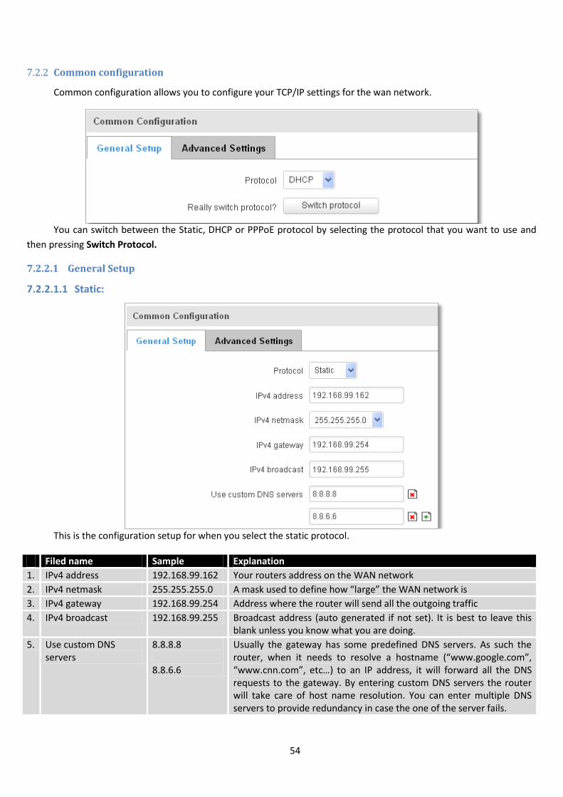
7.2.2 Common configuration
Common configuration allows you to configure your TCP/IP settings for the wan network.
You can switch between the Static, DHCP or PPPoE protocol by selecting the protocol that you want to use and
then pressing Switch Protocol.
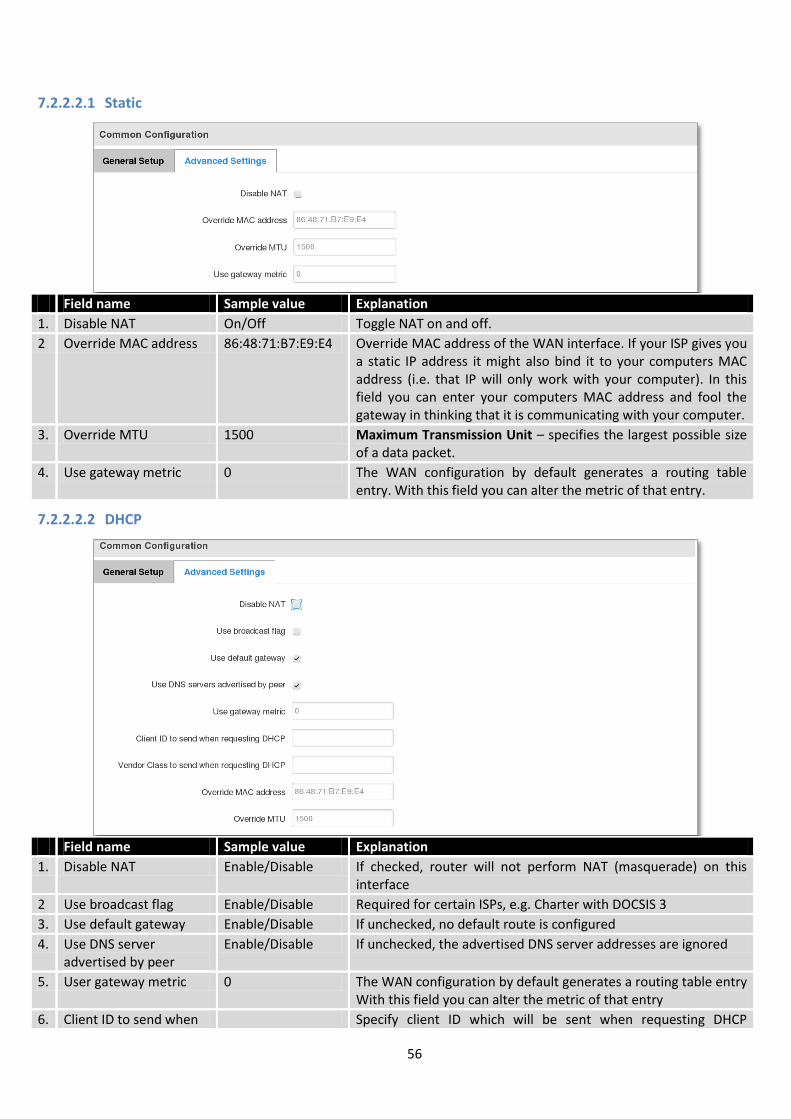
7.2.2.1 General Setup
7.2.2.1.1 Static:
This is the configuration setup for when you select the static protocol.
Filed name Sample Explanation
1. IPv4 address 192.168.99.162 Your routers address on the WAN network
2. IPv4 netmask 255.255.255.0 A mask used to define how “large” the WAN network is
3. IPv4 gateway 192.168.99.254 Address where the router will send all the outgoing traffic
4. IPv4 broadcast 192.168.99.255 Broadcast address (auto generated if not set). It is best to leave this blank unless you know what you are doing.
5. Use custom DNS servers
8.8.8.8 8.8.6.6
Usually the gateway has some predefined DNS servers. As such the router, when it needs to resolve a hostname (“www.google.com”, “www.cnn.com”, etc…) to an IP address, it will forward all the DNS requests to the gateway. By entering custom DNS servers the router will take care of host name resolution. You can enter multiple DNS servers to provide redundancy in case the one of the server fails.
55
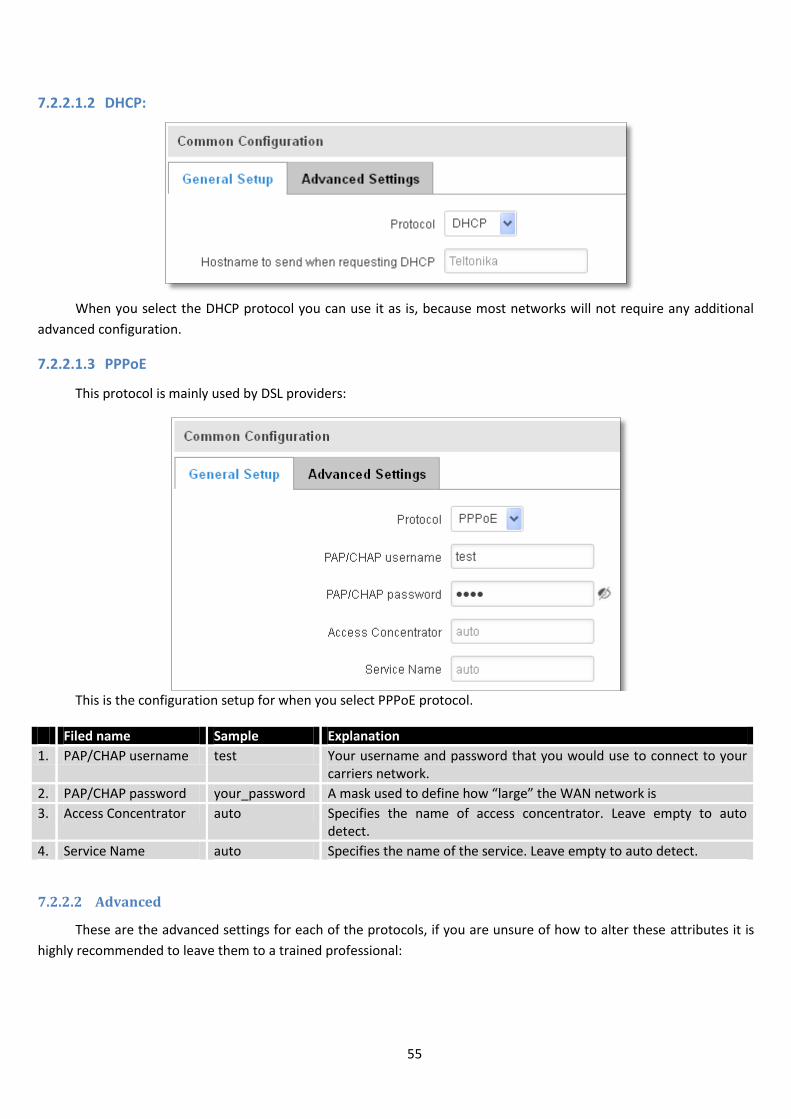
7.2.2.1.2 DHCP:
When you select the DHCP protocol you can use it as is, because most networks will not require any additional
advanced configuration.
7.2.2.1.3 PPPoE
This protocol is mainly used by DSL providers:
This is the configuration setup for when you select PPPoE protocol.
Filed name Sample Explanation
1. PAP/CHAP username test Your username and password that you would use to connect to your carriers network.
2. PAP/CHAP password your_password A mask used to define how “large” the WAN network is
3. Access Concentrator auto Specifies the name of access concentrator. Leave empty to auto detect.
4. Service Name auto Specifies the name of the service. Leave empty to auto detect.
7.2.2.2 Advanced
These are the advanced settings for each of the protocols, if you are unsure of how to alter these attributes it is
highly recommended to leave them to a trained professional:
56
7.2.2.2.1 Static
Field name Sample value Explanation
1. Disable NAT On/Off Toggle NAT on and off.
2 Override MAC address 86:48:71:B7:E9:E4 Override MAC address of the WAN interface. If your ISP gives you a static IP address it might also bind it to your computers MAC address (i.e. that IP will only work with your computer). In this field you can enter your computers MAC address and fool the gateway in thinking that it is communicating with your computer.
3. Override MTU 1500 Maximum Transmission Unit – specifies the largest possible size of a data packet.
4. Use gateway metric 0 The WAN configuration by default generates a routing table entry. With this field you can alter the metric of that entry.
7.2.2.2.2 DHCP
Field name Sample value Explanation
1. Disable NAT Enable/Disable If checked, router will not perform NAT (masquerade) on this interface
2 Use broadcast flag Enable/Disable Required for certain ISPs, e.g. Charter with DOCSIS 3
3. Use default gateway Enable/Disable If unchecked, no default route is configured
4. Use DNS server advertised by peer
Enable/Disable If unchecked, the advertised DNS server addresses are ignored
5. User gateway metric 0 The WAN configuration by default generates a routing table entry With this field you can alter the metric of that entry
6. Client ID to send when Specify client ID which will be sent when requesting DHCP
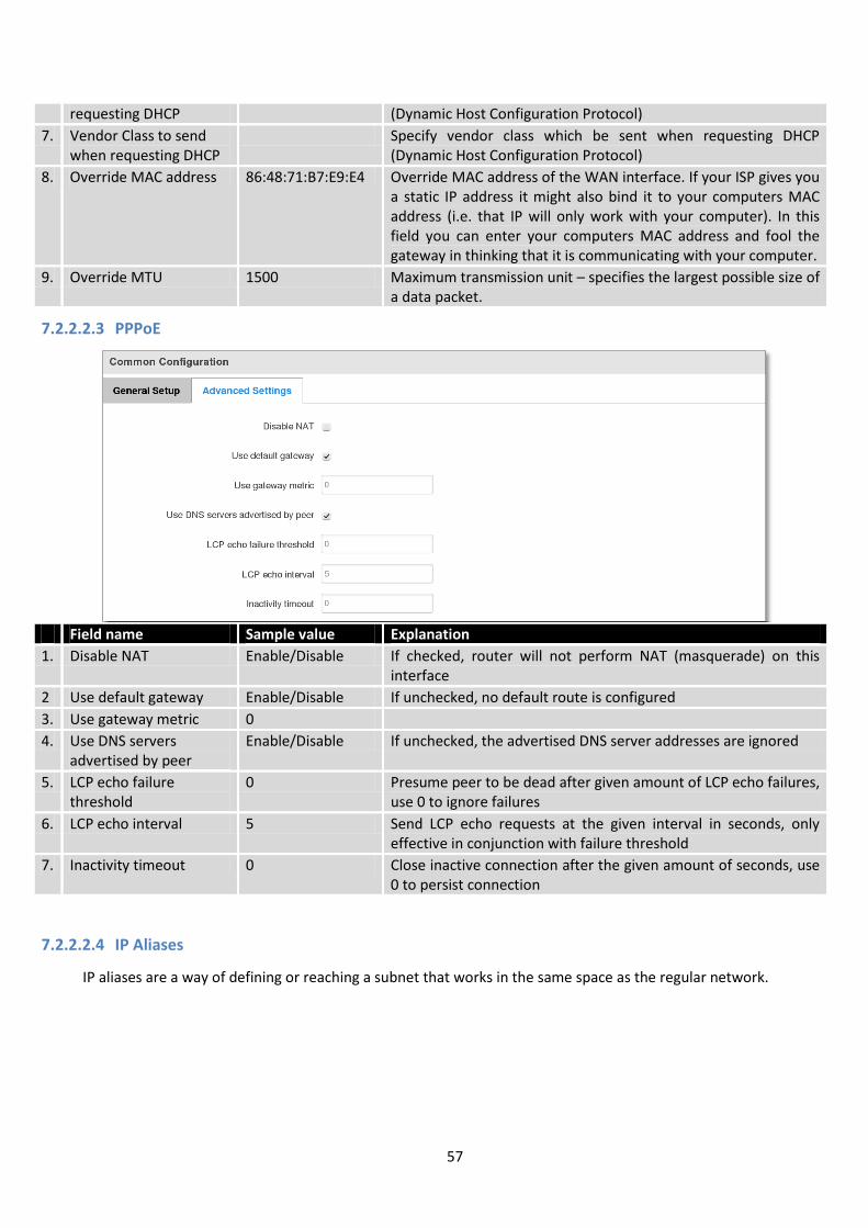
57
requesting DHCP (Dynamic Host Configuration Protocol)
7. Vendor Class to send when requesting DHCP
Specify vendor class which be sent when requesting DHCP (Dynamic Host Configuration Protocol)
8. Override MAC address 86:48:71:B7:E9:E4 Override MAC address of the WAN interface. If your ISP gives you a static IP address it might also bind it to your computers MAC address (i.e. that IP will only work with your computer). In this field you can enter your computers MAC address and fool the gateway in thinking that it is communicating with your computer.
9. Override MTU 1500 Maximum transmission unit – specifies the largest possible size of a data packet.
7.2.2.2.3 PPPoE
Field name Sample value Explanation
1. Disable NAT Enable/Disable If checked, router will not perform NAT (masquerade) on this interface
2 Use default gateway Enable/Disable If unchecked, no default route is configured
3. Use gateway metric 0
4. Use DNS servers advertised by peer
Enable/Disable If unchecked, the advertised DNS server addresses are ignored
5. LCP echo failure threshold
0 Presume peer to be dead after given amount of LCP echo failures, use 0 to ignore failures
6. LCP echo interval 5 Send LCP echo requests at the given interval in seconds, only effective in conjunction with failure threshold
7. Inactivity timeout 0 Close inactive connection after the given amount of seconds, use 0 to persist connection
7.2.2.2.4 IP Aliases
IP aliases are a way of defining or reaching a subnet that works in the same space as the regular network.
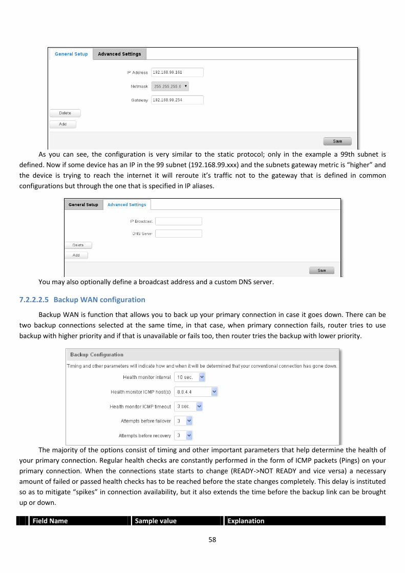
58
As you can see, the configuration is very similar to the static protocol; only in the example a 99th subnet is
defined. Now if some device has an IP in the 99 subnet (192.168.99.xxx) and the subnets gateway metric is “higher” and
the device is trying to reach the internet it will reroute it’s traffic not to the gateway that is defined in common
configurations but through the one that is specified in IP aliases.
You may also optionally define a broadcast address and a custom DNS server.
7.2.2.2.5 Backup WAN configuration
Backup WAN is function that allows you to back up your primary connection in case it goes down. There can be
two backup connections selected at the same time, in that case, when primary connection fails, router tries to use
backup with higher priority and if that is unavailable or fails too, then router tries the backup with lower priority.
The majority of the options consist of timing and other important parameters that help determine the health of
your primary connection. Regular health checks are constantly performed in the form of ICMP packets (Pings) on your
primary connection. When the connections state starts to change (READY->NOT READY and vice versa) a necessary
amount of failed or passed health checks has to be reached before the state changes completely. This delay is instituted
so as to mitigate “spikes” in connection availability, but it also extends the time before the backup link can be brought
up or down.
Field Name Sample value Explanation
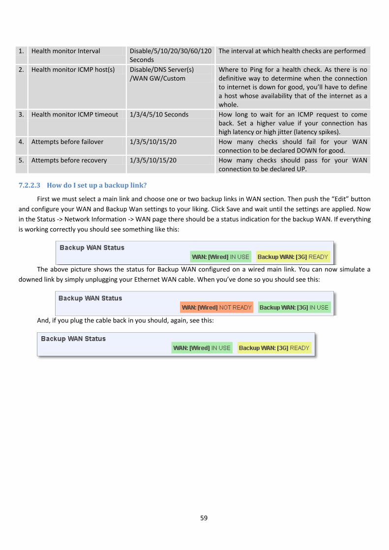
59
1. Health monitor Interval Disable/5/10/20/30/60/120 Seconds
The interval at which health checks are performed
2. Health monitor ICMP host(s) Disable/DNS Server(s) /WAN GW/Custom
Where to Ping for a health check. As there is no definitive way to determine when the connection to internet is down for good, you’ll have to define a host whose availability that of the internet as a whole.
3. Health monitor ICMP timeout 1/3/4/5/10 Seconds How long to wait for an ICMP request to come back. Set a higher value if your connection has high latency or high jitter (latency spikes).
4. Attempts before failover 1/3/5/10/15/20 How many checks should fail for your WAN connection to be declared DOWN for good.
5. Attempts before recovery 1/3/5/10/15/20 How many checks should pass for your WAN connection to be declared UP.
7.2.2.3 How do I set up a backup link?
First we must select a main link and choose one or two backup links in WAN section. Then push the “Edit” button
and configure your WAN and Backup Wan settings to your liking. Click Save and wait until the settings are applied. Now
in the Status -> Network Information -> WAN page there should be a status indication for the backup WAN. If everything
is working correctly you should see something like this:
The above picture shows the status for Backup WAN configured on a wired main link. You can now simulate a
downed link by simply unplugging your Ethernet WAN cable. When you’ve done so you should see this:
And, if you plug the cable back in you should, again, see this:
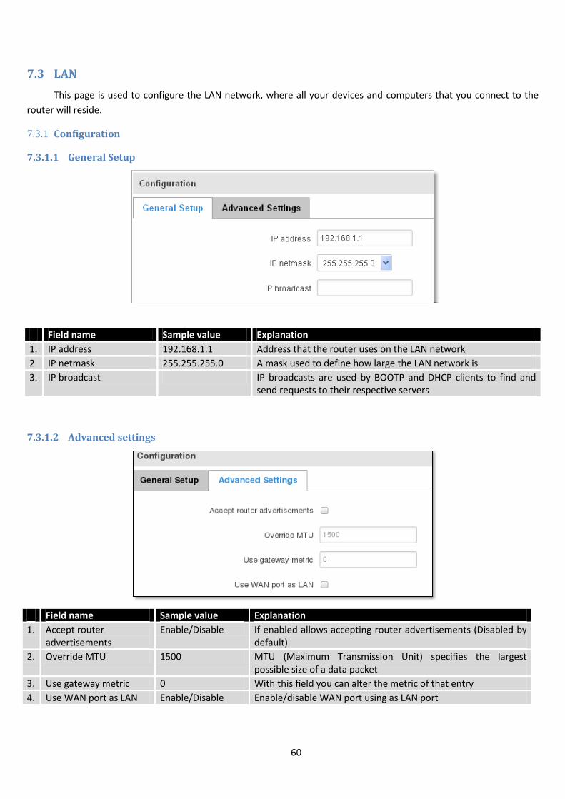
60
7.3 LAN
This page is used to configure the LAN network, where all your devices and computers that you connect to the
router will reside.
7.3.1 Configuration
7.3.1.1 General Setup
Field name Sample value Explanation
1. IP address 192.168.1.1 Address that the router uses on the LAN network
2 IP netmask 255.255.255.0 A mask used to define how large the LAN network is
3. IP broadcast IP broadcasts are used by BOOTP and DHCP clients to find and send requests to their respective servers
7.3.1.2 Advanced settings
Field name Sample value Explanation
1. Accept router advertisements
Enable/Disable If enabled allows accepting router advertisements (Disabled by default)
2. Override MTU 1500 MTU (Maximum Transmission Unit) specifies the largest possible size of a data packet
3. Use gateway metric 0 With this field you can alter the metric of that entry
4. Use WAN port as LAN Enable/Disable Enable/disable WAN port using as LAN port
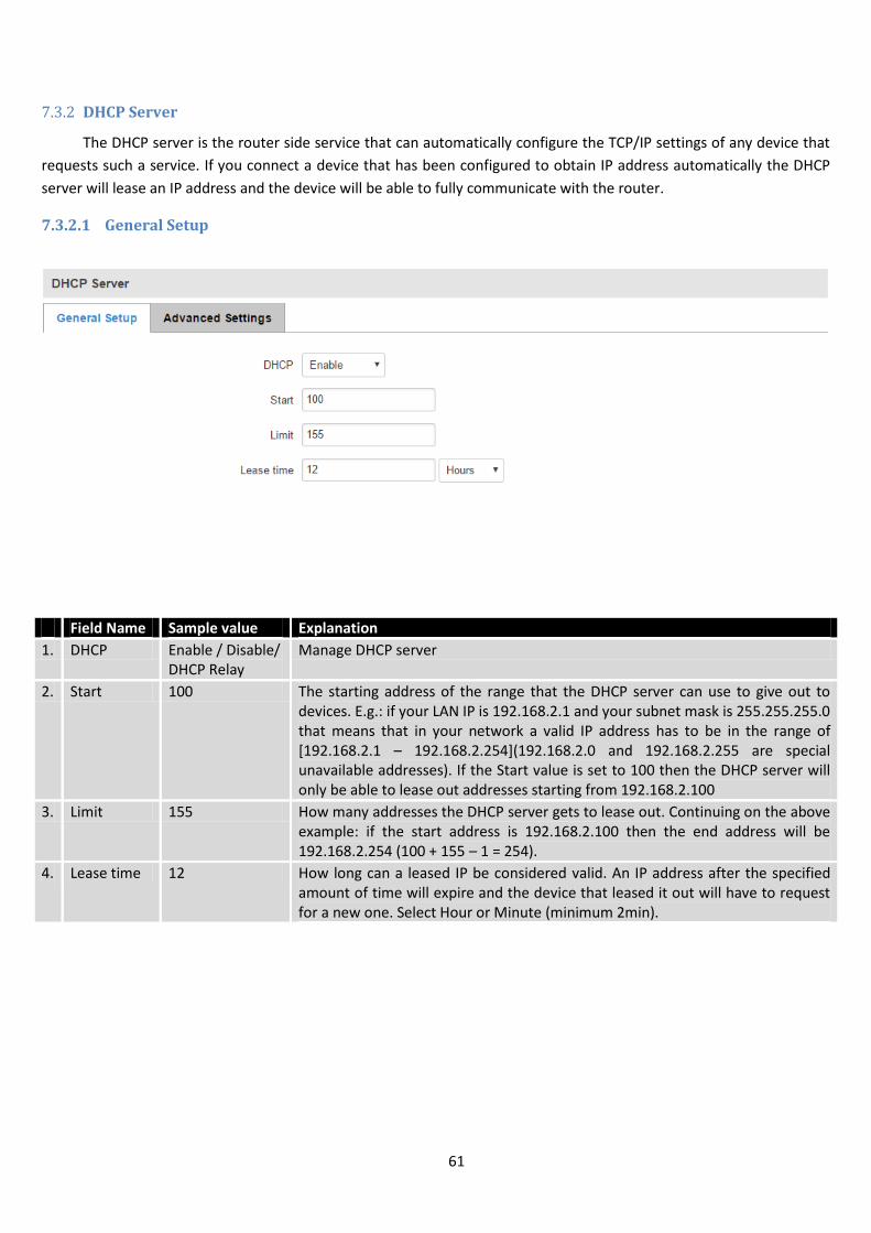
61
7.3.2 DHCP Server
The DHCP server is the router side service that can automatically configure the TCP/IP settings of any device that
requests such a service. If you connect a device that has been configured to obtain IP address automatically the DHCP
server will lease an IP address and the device will be able to fully communicate with the router.
7.3.2.1 General Setup
Field Name Sample value Explanation
1. DHCP Enable / Disable/ DHCP Relay
Manage DHCP server
2. Start 100 The starting address of the range that the DHCP server can use to give out to devices. E.g.: if your LAN IP is 192.168.2.1 and your subnet mask is 255.255.255.0 that means that in your network a valid IP address has to be in the range of [192.168.2.1 – 192.168.2.254](192.168.2.0 and 192.168.2.255 are special unavailable addresses). If the Start value is set to 100 then the DHCP server will only be able to lease out addresses starting from 192.168.2.100
3. Limit 155 How many addresses the DHCP server gets to lease out. Continuing on the above example: if the start address is 192.168.2.100 then the end address will be 192.168.2.254 (100 + 155 – 1 = 254).
4. Lease time 12 How long can a leased IP be considered valid. An IP address after the specified amount of time will expire and the device that leased it out will have to request for a new one. Select Hour or Minute (minimum 2min).

62
7.3.2.2 Advanced settings
You can also define some advanced options that specify how the DHCP server will operate on your LAN network.
7.3.2.3 Static Leases
This page is used to configure static IP leases.
7.3.2.4 IP Aliases
7.3.2.4.1 General Setup
IP aliases are the way of defining or reaching a subnet that works in the same space as the regular network.
Field Name Sample Value Explanation
1. Dynamic DHCP Checked/Unchecked Dynamically allocate client addresses, if set to 0 only clients present in the ethers files are served
2. Force Checked/Unchecked Forces DHCP serving even if another DHCP server is detected on the same network segment.
3. IP netmask You can override your LAN netmask here to make the DHCP server think it’s serving a larger or a smaller network than it actually is.
4. DHCP Options Additional options to be added for this DHCP server. For example with '26,1470' or 'option:mtu, 1470' you can assign an MTU per DHCP. Your client must accept MTU by DHCP for this to work.
Field Name Sample Value Explanation
1. Hostname Printer Name which will be linked with IP address.
2. MAC address 10:a5:d0:70:9c:72 (192.168.1.104) Device MAC address
3. IP address 192.168.1.104 Device IP address
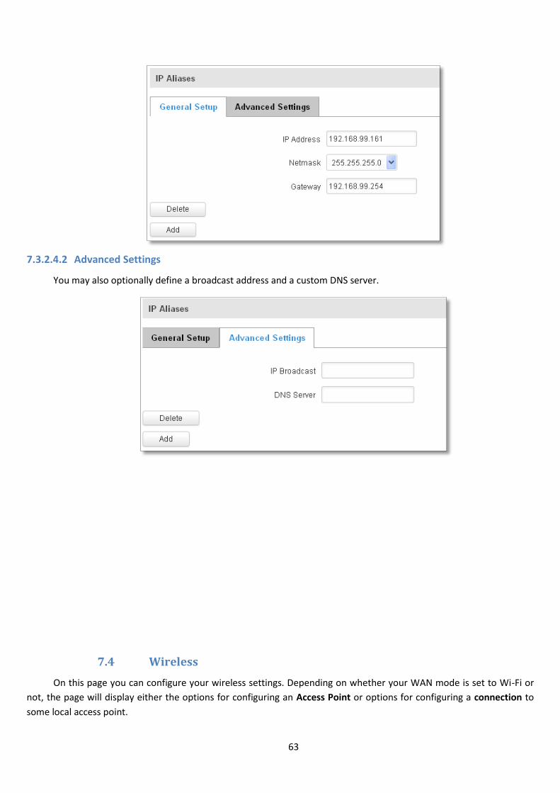
63
7.3.2.4.2 Advanced Settings
You may also optionally define a broadcast address and a custom DNS server.
7.4 Wireless
On this page you can configure your wireless settings. Depending on whether your WAN mode is set to Wi-Fi or
not, the page will display either the options for configuring an Access Point or options for configuring a connection to
some local access point.

64
Access Point:
Here you can see the Overview of the wireless configuration. It is divided into two main sections – device and
interface. One is dedicated to configuring hardware parameters other – software.
Here you can toggle the availability of the wireless radio and the physical channel frequency.
Important note: As seen in the picture you should always Save before toggling the radio on and off.
SSID – Your wireless networks identification string. This is the name of your Wi-Fi network. When other Wi-Fi
capable computers or devices scan the area for Wi-Fi networks they will see your network with this name.
Hide SSID – Will render your SSID hidden from other devices that try to scan the area.
Connect to WRP100 automatically – let Teltonika WRP100 wireless repeater connect to this router automatically.
7.4.1.1 Device
7.4.1.1.1 Advanced Settings
Here you can configure more advanced parameters:
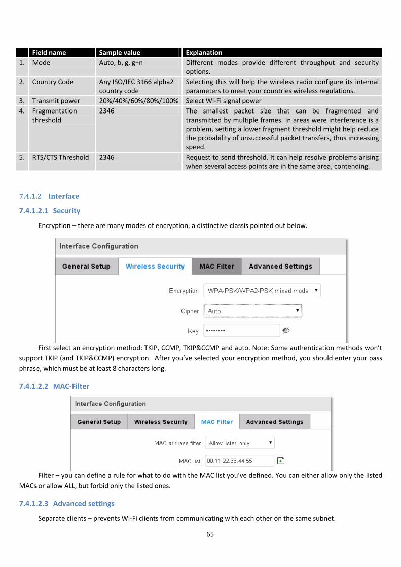
65
Field name Sample value Explanation
1. Mode Auto, b, g, g+n Different modes provide different throughput and security options.
2. Country Code Any ISO/IEC 3166 alpha2 country code
Selecting this will help the wireless radio configure its internal parameters to meet your countries wireless regulations.
3. Transmit power 20%/40%/60%/80%/100% Select Wi-Fi signal power
4. Fragmentation threshold
2346 The smallest packet size that can be fragmented and transmitted by multiple frames. In areas were interference is a problem, setting a lower fragment threshold might help reduce the probability of unsuccessful packet transfers, thus increasing speed.
5. RTS/CTS Threshold 2346 Request to send threshold. It can help resolve problems arising when several access points are in the same area, contending.
7.4.1.2 Interface
7.4.1.2.1 Security
Encryption – there are many modes of encryption, a distinctive classis pointed out below.
First select an encryption method: TKIP, CCMP, TKIP&CCMP and auto. Note: Some authentication methods won’t
support TKIP (and TKIP&CCMP) encryption. After you’ve selected your encryption method, you should enter your pass
phrase, which must be at least 8 characters long.
7.4.1.2.2 MAC-Filter
Filter – you can define a rule for what to do with the MAC list you’ve defined. You can either allow only the listed
MACs or allow ALL, but forbid only the listed ones.
7.4.1.2.3 Advanced settings
Separate clients – prevents Wi-Fi clients from communicating with each other on the same subnet.
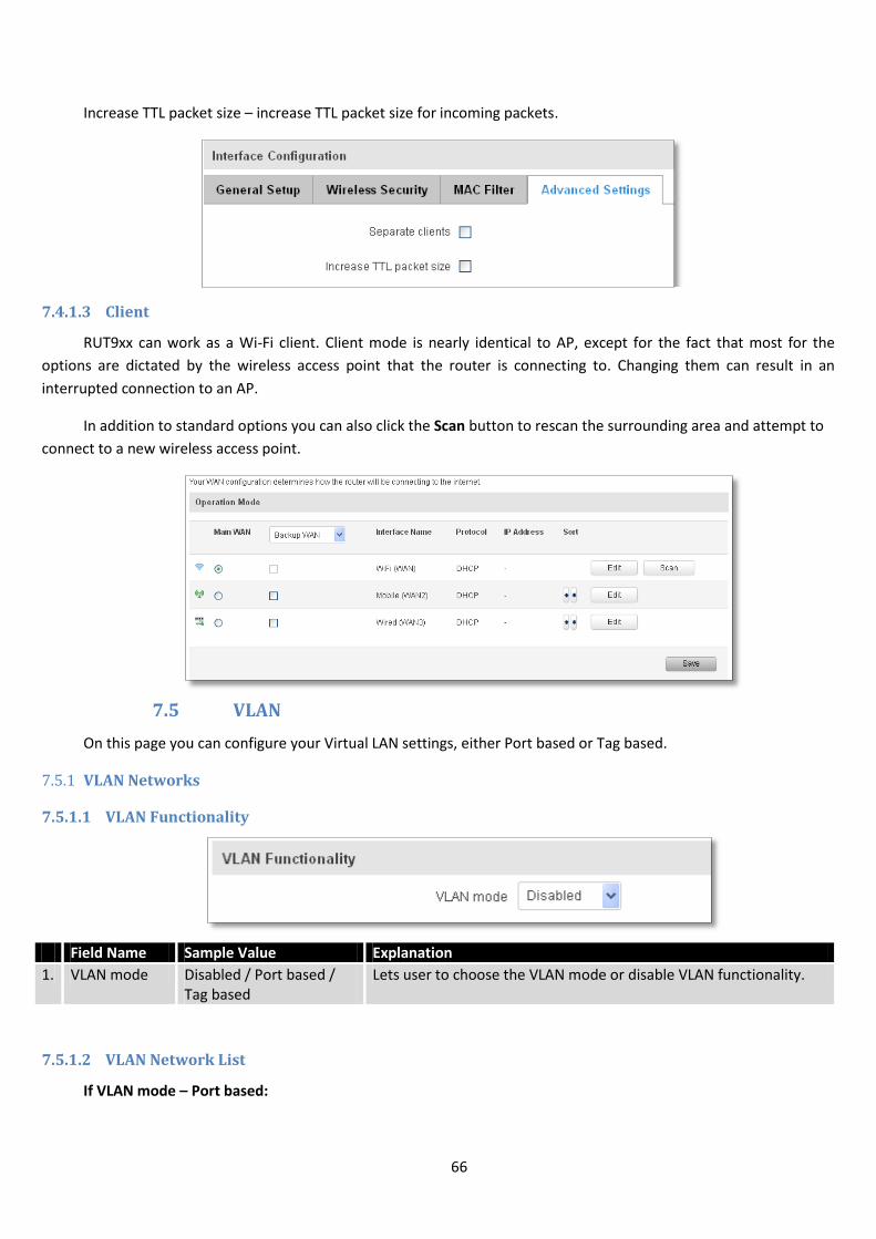
66
Increase TTL packet size – increase TTL packet size for incoming packets.
7.4.1.3 Client
RUT9xx can work as a Wi-Fi client. Client mode is nearly identical to AP, except for the fact that most for the
options are dictated by the wireless access point that the router is connecting to. Changing them can result in an
interrupted connection to an AP.
In addition to standard options you can also click the Scan button to rescan the surrounding area and attempt to
connect to a new wireless access point.
7.5 VLAN
On this page you can configure your Virtual LAN settings, either Port based or Tag based.
7.5.1 VLAN Networks
7.5.1.1 VLAN Functionality
Field Name Sample Value Explanation
1. VLAN mode Disabled / Port based / Tag based
Lets user to choose the VLAN mode or disable VLAN functionality.
7.5.1.2 VLAN Network List
If VLAN mode – Port based:
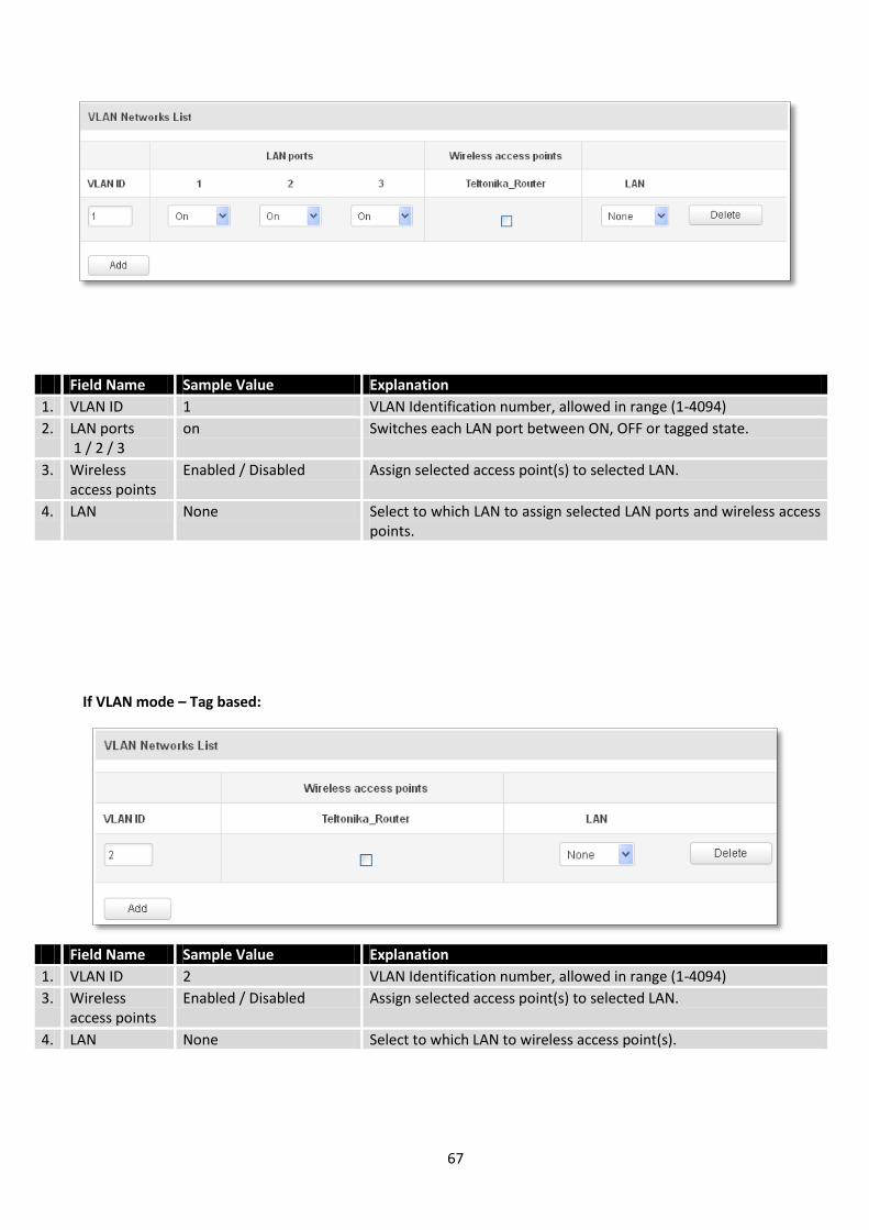
67
Field Name Sample Value Explanation
1. VLAN ID 1 VLAN Identification number, allowed in range (1-4094)
2. LAN ports 1 / 2 / 3
on Switches each LAN port between ON, OFF or tagged state.
3. Wireless access points
Enabled / Disabled Assign selected access point(s) to selected LAN.
4. LAN None Select to which LAN to assign selected LAN ports and wireless access points.
If VLAN mode – Tag based:
Field Name Sample Value Explanation
1. VLAN ID 2 VLAN Identification number, allowed in range (1-4094)
3. Wireless access points
Enabled / Disabled Assign selected access point(s) to selected LAN.
4. LAN None Select to which LAN to wireless access point(s).

68
7.5.2 LAN Networks
In this page you can create extra LAN networks, and assign them with LAN Ports and wireless access points. You
can get extra information on how to configure any of your LAN’s settings in section – 7.3 LAN
Field Name Sample Value Explanation
1. LAN name Lan Specifies new LAN name
2. Interface name
eth0 tap0 Specifies LAN interface name
7.6 Firewall
In this section we will look over the various firewall features that come with RUT9.
7.6.1 General Settings
The routers firewall is a standard Linux iptables package, which uses routing chains and policies to facilitate
control over inbound and outbound traffic.
Field Name Sample value Explanation
1. Drop Invalid packets
Checked/Unchecked A “Drop” action is performed on a packet that is determined to be invalid
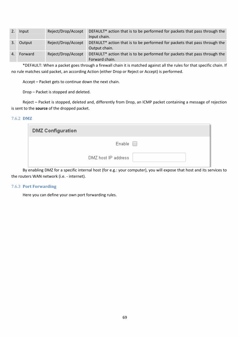
69
2. Input Reject/Drop/Accept DEFAULT* action that is to be performed for packets that pass through the Input chain.
3. Output Reject/Drop/Accept DEFAULT* action that is to be performed for packets that pass through the Output chain.
4. Forward Reject/Drop/Accept DEFAULT* action that is to be performed for packets that pass through the Forward chain.
*DEFAULT: When a packet goes through a firewall chain it is matched against all the rules for that specific chain. If
no rule matches said packet, an according Action (either Drop or Reject or Accept) is performed.
Accept – Packet gets to continue down the next chain.
Drop – Packet is stopped and deleted.
Reject – Packet is stopped, deleted and, differently from Drop, an ICMP packet containing a message of rejection
is sent to the source of the dropped packet.
7.6.2 DMZ
By enabling DMZ for a specific internal host (for e.g.: your computer), you will expose that host and its services to
the routers WAN network (i.e. - internet).
7.6.3 Port Forwarding
Here you can define your own port forwarding rules.
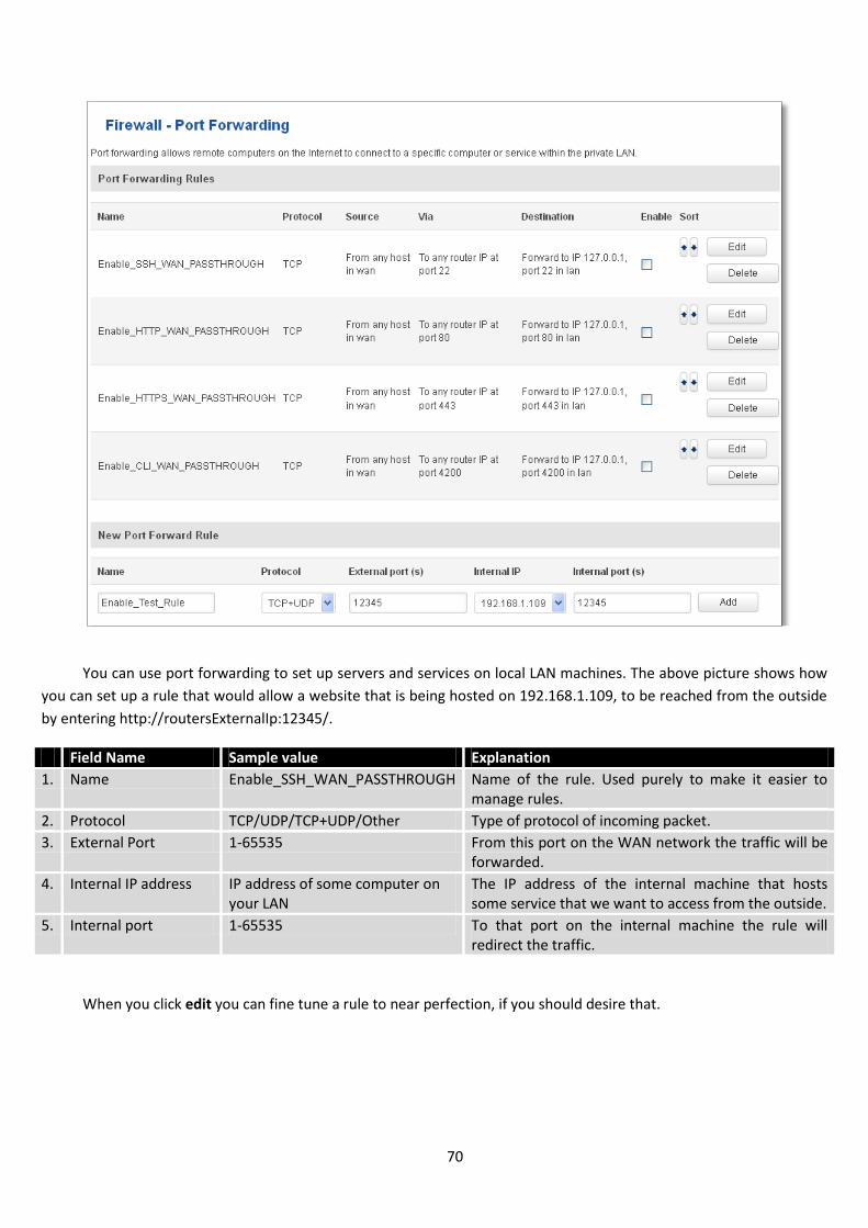
70
You can use port forwarding to set up servers and services on local LAN machines. The above picture shows how
you can set up a rule that would allow a website that is being hosted on 192.168.1.109, to be reached from the outside
by entering http://routersExternalIp:12345/.
Field Name Sample value Explanation
1. Name Enable_SSH_WAN_PASSTHROUGH Name of the rule. Used purely to make it easier to manage rules.
2. Protocol TCP/UDP/TCP+UDP/Other Type of protocol of incoming packet.
3. External Port 1-65535 From this port on the WAN network the traffic will be forwarded.
4. Internal IP address IP address of some computer on your LAN
The IP address of the internal machine that hosts some service that we want to access from the outside.
5. Internal port 1-65535 To that port on the internal machine the rule will redirect the traffic.
When you click edit you can fine tune a rule to near perfection, if you should desire that.
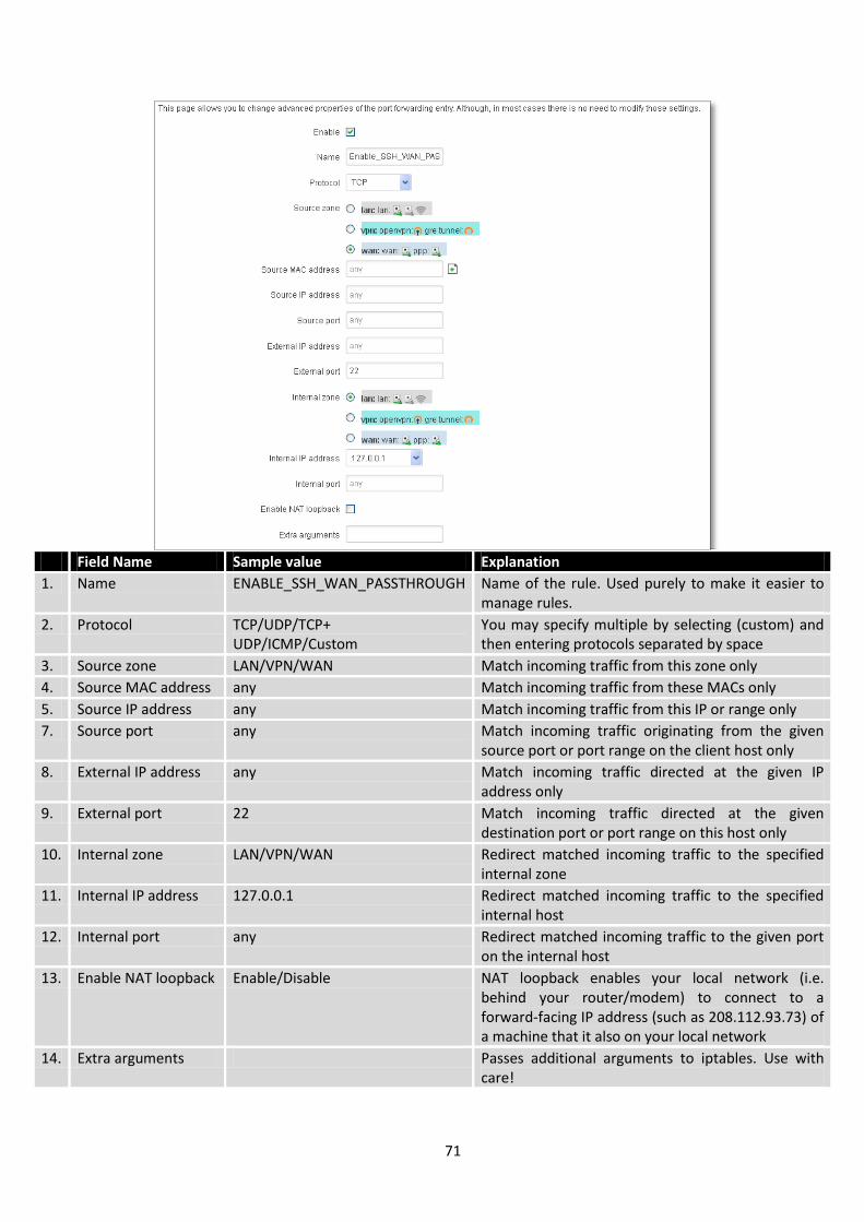
71
Field Name Sample value Explanation
1. Name ENABLE_SSH_WAN_PASSTHROUGH Name of the rule. Used purely to make it easier to manage rules.
2. Protocol TCP/UDP/TCP+ UDP/ICMP/Custom
You may specify multiple by selecting (custom) and then entering protocols separated by space
3. Source zone LAN/VPN/WAN Match incoming traffic from this zone only
4. Source MAC address any Match incoming traffic from these MACs only
5. Source IP address any Match incoming traffic from this IP or range only
7. Source port any Match incoming traffic originating from the given source port or port range on the client host only
8. External IP address any Match incoming traffic directed at the given IP address only
9. External port 22 Match incoming traffic directed at the given destination port or port range on this host only
10. Internal zone LAN/VPN/WAN Redirect matched incoming traffic to the specified internal zone
11. Internal IP address 127.0.0.1 Redirect matched incoming traffic to the specified internal host
12. Internal port any Redirect matched incoming traffic to the given port on the internal host
13. Enable NAT loopback Enable/Disable NAT loopback enables your local network (i.e. behind your router/modem) to connect to a forward-facing IP address (such as 208.112.93.73) of a machine that it also on your local network
14. Extra arguments Passes additional arguments to iptables. Use with care!
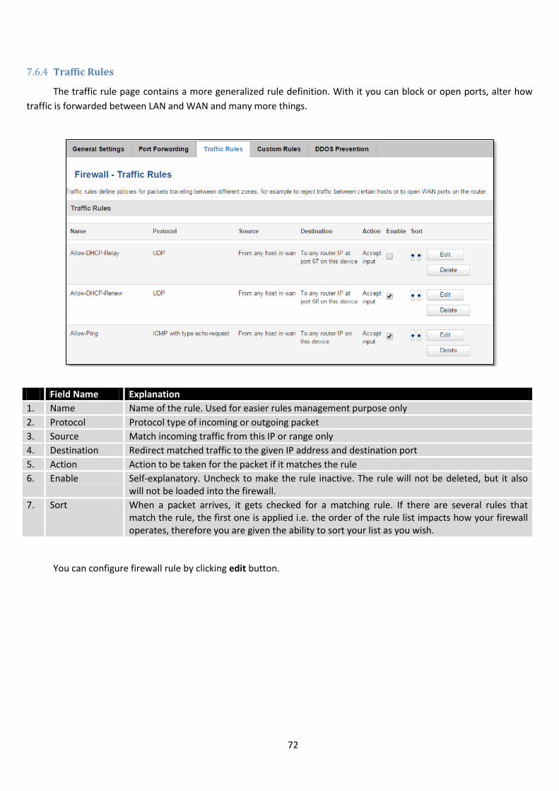
72
7.6.4 Traffic Rules
The traffic rule page contains a more generalized rule definition. With it you can block or open ports, alter how
traffic is forwarded between LAN and WAN and many more things.
Field Name Explanation
1. Name Name of the rule. Used for easier rules management purpose only
2. Protocol Protocol type of incoming or outgoing packet
3. Source Match incoming traffic from this IP or range only
4. Destination Redirect matched traffic to the given IP address and destination port
5. Action Action to be taken for the packet if it matches the rule
6. Enable Self-explanatory. Uncheck to make the rule inactive. The rule will not be deleted, but it also will not be loaded into the firewall.
7. Sort When a packet arrives, it gets checked for a matching rule. If there are several rules that match the rule, the first one is applied i.e. the order of the rule list impacts how your firewall operates, therefore you are given the ability to sort your list as you wish.
You can configure firewall rule by clicking edit button.
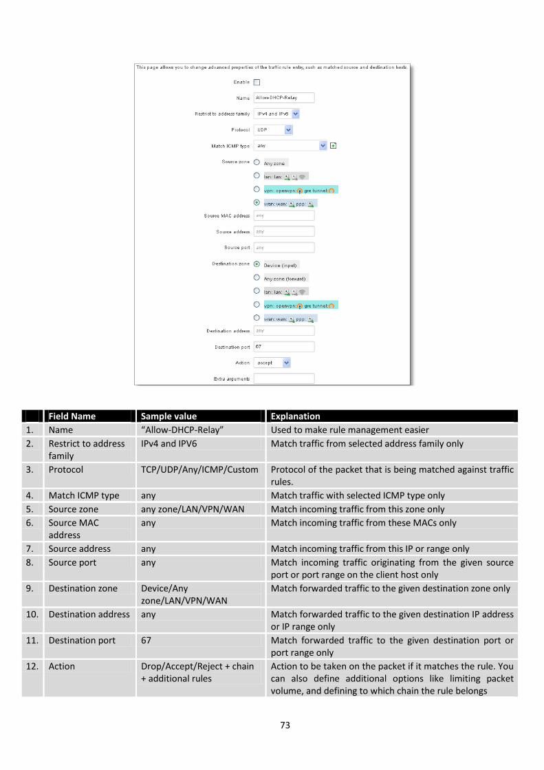
73
Field Name Sample value Explanation
1. Name “Allow-DHCP-Relay” Used to make rule management easier
2. Restrict to address family
IPv4 and IPV6 Match traffic from selected address family only
3. Protocol TCP/UDP/Any/ICMP/Custom Protocol of the packet that is being matched against traffic rules.
4. Match ICMP type any Match traffic with selected ICMP type only
5. Source zone any zone/LAN/VPN/WAN Match incoming traffic from this zone only
6. Source MAC address
any Match incoming traffic from these MACs only
7. Source address any Match incoming traffic from this IP or range only
8. Source port any Match incoming traffic originating from the given source port or port range on the client host only
9. Destination zone Device/Any zone/LAN/VPN/WAN
Match forwarded traffic to the given destination zone only
10. Destination address any Match forwarded traffic to the given destination IP address or IP range only
11. Destination port 67 Match forwarded traffic to the given destination port or port range only
12. Action Drop/Accept/Reject + chain + additional rules
Action to be taken on the packet if it matches the rule. You can also define additional options like limiting packet volume, and defining to which chain the rule belongs
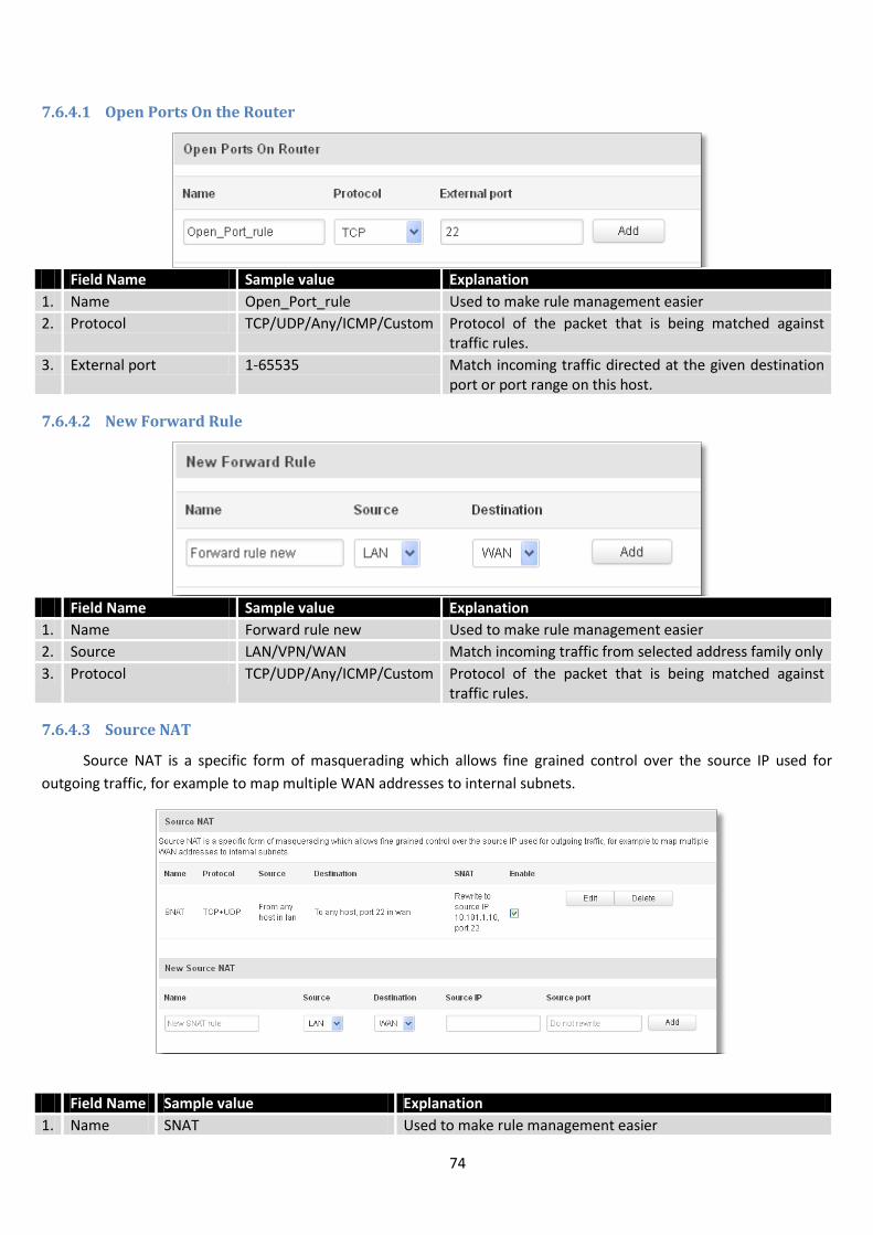
74
7.6.4.1 Open Ports On the Router
Field Name Sample value Explanation
1. Name Open_Port_rule Used to make rule management easier
2. Protocol TCP/UDP/Any/ICMP/Custom Protocol of the packet that is being matched against traffic rules.
3. External port 1-65535 Match incoming traffic directed at the given destination port or port range on this host.
7.6.4.2 New Forward Rule
Field Name Sample value Explanation
1. Name Forward rule new Used to make rule management easier
2. Source LAN/VPN/WAN Match incoming traffic from selected address family only
3. Protocol TCP/UDP/Any/ICMP/Custom Protocol of the packet that is being matched against traffic rules.
7.6.4.3 Source NAT
Source NAT is a specific form of masquerading which allows fine grained control over the source IP used for
outgoing traffic, for example to map multiple WAN addresses to internal subnets.
Field Name Sample value Explanation
1. Name SNAT Used to make rule management easier
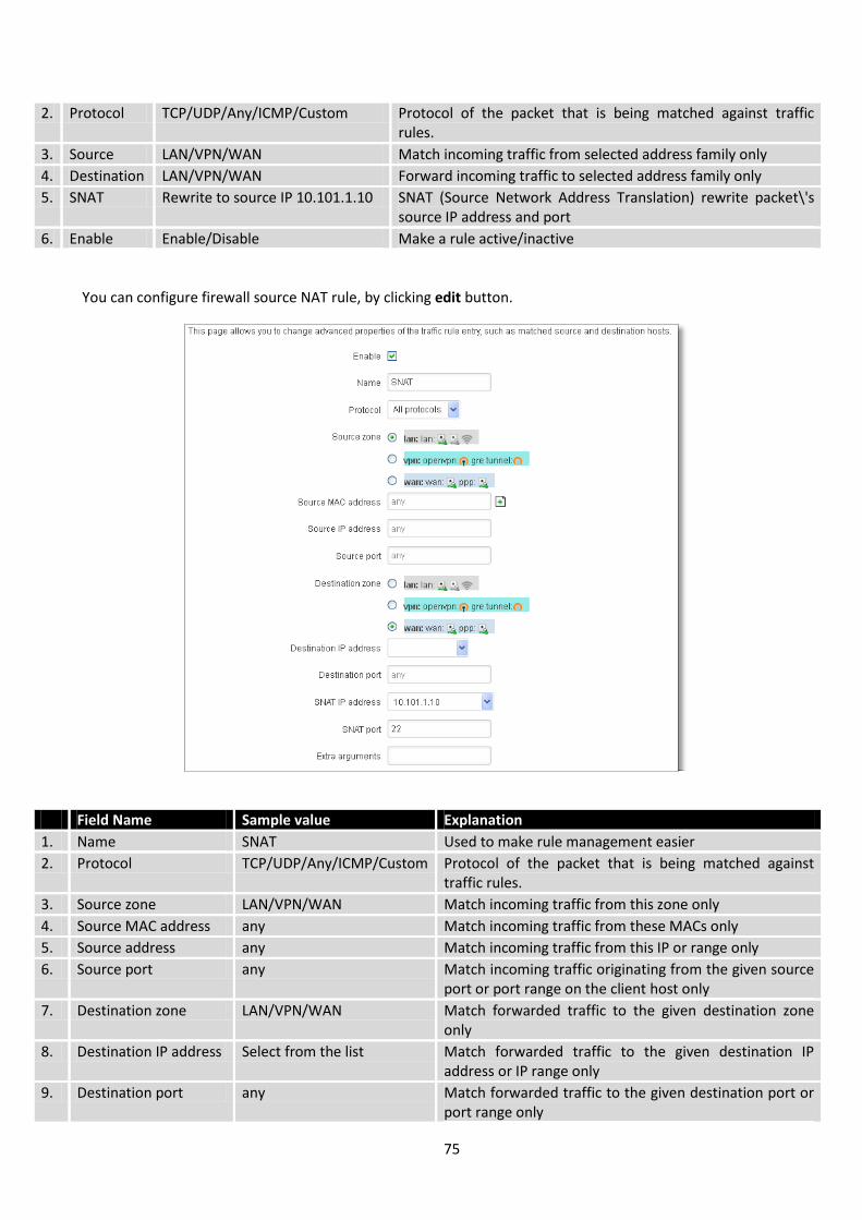
75
2. Protocol TCP/UDP/Any/ICMP/Custom Protocol of the packet that is being matched against traffic rules.
3. Source LAN/VPN/WAN Match incoming traffic from selected address family only
4. Destination LAN/VPN/WAN Forward incoming traffic to selected address family only
5. SNAT Rewrite to source IP 10.101.1.10 SNAT (Source Network Address Translation) rewrite packet\'s source IP address and port
6. Enable Enable/Disable Make a rule active/inactive
You can configure firewall source NAT rule, by clicking edit button.
Field Name Sample value Explanation
1. Name SNAT Used to make rule management easier
2. Protocol TCP/UDP/Any/ICMP/Custom Protocol of the packet that is being matched against traffic rules.
3. Source zone LAN/VPN/WAN Match incoming traffic from this zone only
4. Source MAC address any Match incoming traffic from these MACs only
5. Source address any Match incoming traffic from this IP or range only
6. Source port any Match incoming traffic originating from the given source port or port range on the client host only
7. Destination zone LAN/VPN/WAN Match forwarded traffic to the given destination zone only
8. Destination IP address Select from the list Match forwarded traffic to the given destination IP address or IP range only
9. Destination port any Match forwarded traffic to the given destination port or port range only
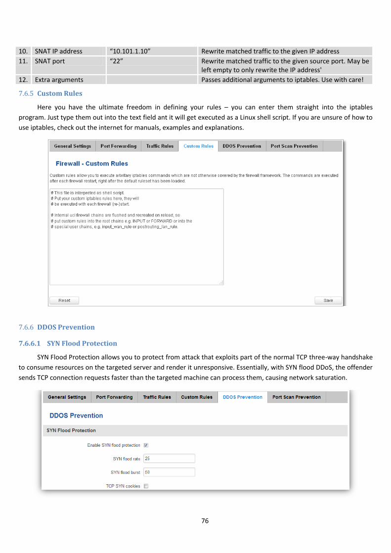
76
10. SNAT IP address “10.101.1.10” Rewrite matched traffic to the given IP address
11. SNAT port “22” Rewrite matched traffic to the given source port. May be left empty to only rewrite the IP address'
12. Extra arguments Passes additional arguments to iptables. Use with care!
7.6.5 Custom Rules
Here you have the ultimate freedom in defining your rules – you can enter them straight into the iptables
program. Just type them out into the text field ant it will get executed as a Linux shell script. If you are unsure of how to
use iptables, check out the internet for manuals, examples and explanations.
7.6.6 DDOS Prevention
7.6.6.1 SYN Flood Protection
SYN Flood Protection allows you to protect from attack that exploits part of the normal TCP three-way handshake
to consume resources on the targeted server and render it unresponsive. Essentially, with SYN flood DDoS, the offender
sends TCP connection requests faster than the targeted machine can process them, causing network saturation.
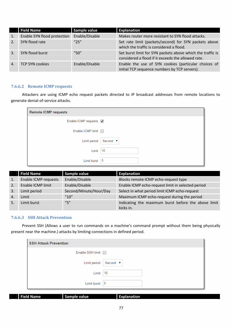
77
Field Name Sample value Explanation
1. Enable SYN flood protection Enable/Disable Makes router more resistant to SYN flood attacks.
2. SYN flood rate “25” Set rate limit (packets/second) for SYN packets above which the traffic is considered a flood.
3. SYN flood burst “50” Set burst limit for SYN packets above which the traffic is considered a flood if it exceeds the allowed rate.
4. TCP SYN cookies Enable/Disable Enable the use of SYN cookies (particular choices of initial TCP sequence numbers by TCP servers).
7.6.6.2 Remote ICMP requests
Attackers are using ICMP echo request packets directed to IP broadcast addresses from remote locations to
generate denial-of-service attacks.
Field Name Sample value Explanation
1. Enable ICMP requests Enable/Disable Blocks remote ICMP echo-request type
2. Enable ICMP limit Enable/Disable Enable ICMP echo-request limit in selected period
3. Limit period Second/Minute/Hour/Day Select in what period limit ICMP echo-request
4. Limit “10” Maximum ICMP echo-request during the period
5. Limit burst “5” Indicating the maximum burst before the above limit kicks in.
7.6.6.3 SSH Attack Prevention
Prevent SSH (Allows a user to run commands on a machine's command prompt without them being physically
present near the machine.) attacks by limiting connections in defined period.
Field Name Sample value Explanation
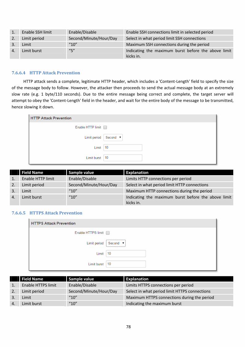
78
1. Enable SSH limit Enable/Disable Enable SSH connections limit in selected period
2. Limit period Second/Minute/Hour/Day Select in what period limit SSH connections
3. Limit “10” Maximum SSH connections during the period
4. Limit burst “5” Indicating the maximum burst before the above limit kicks in.
7.6.6.4 HTTP Attack Prevention
HTTP attack sends a complete, legitimate HTTP header, which includes a 'Content-Length' field to specify the size
of the message body to follow. However, the attacker then proceeds to send the actual message body at an extremely
slow rate (e.g. 1 byte/110 seconds). Due to the entire message being correct and complete, the target server will
attempt to obey the 'Content-Length' field in the header, and wait for the entire body of the message to be transmitted,
hence slowing it down.
Field Name Sample value Explanation
1. Enable HTTP limit Enable/Disable Limits HTTP connections per period
2. Limit period Second/Minute/Hour/Day Select in what period limit HTTP connections
3. Limit “10” Maximum HTTP connections during the period
4. Limit burst “10” Indicating the maximum burst before the above limit kicks in.
7.6.6.5 HTTPS Attack Prevention
Field Name Sample value Explanation
1. Enable HTTPS limit Enable/Disable Limits HTTPS connections per period
2. Limit period Second/Minute/Hour/Day Select in what period limit HTTPS connections
3. Limit “10” Maximum HTTPS connections during the period
4. Limit burst “10” Indicating the maximum burst
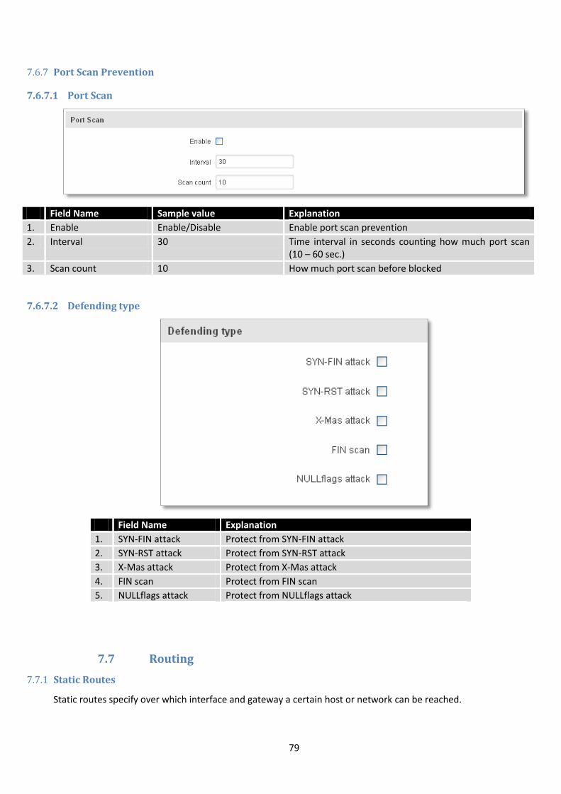
79
7.6.7 Port Scan Prevention
7.6.7.1 Port Scan
Field Name Sample value Explanation
1. Enable Enable/Disable Enable port scan prevention
2. Interval 30 Time interval in seconds counting how much port scan (10 – 60 sec.)
3. Scan count 10 How much port scan before blocked
7.6.7.2 Defending type
Field Name Explanation
1. SYN-FIN attack Protect from SYN-FIN attack
2. SYN-RST attack Protect from SYN-RST attack
3. X-Mas attack Protect from X-Mas attack
4. FIN scan Protect from FIN scan
5. NULLflags attack Protect from NULLflags attack
7.7 Routing
7.7.1 Static Routes
Static routes specify over which interface and gateway a certain host or network can be reached.
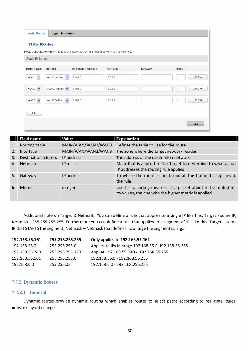
80
Field name Value Explanation
1. Routing table MAIN/WAN/WAN2/WAN3 Defines the table to use for the route
2. Interface MAIN/WAN/WAN2/WAN3 The zone where the target network resides
3. Destination address IP address The address of the destination network
4. Netmask IP mask Mask that is applied to the Target to determine to what actual IP addresses the routing rule applies
5. Gateway IP address To where the router should send all the traffic that applies to the rule
6. Metric integer Used as a sorting measure. If a packet about to be routed fits two rules, the one with the higher metric is applied.
Additional note on Target & Netmask: You can define a rule that applies to a single IP like this: Target - some IP;
Netmask - 255.255.255.255. Furthermore you can define a rule that applies to a segment of IPs like this: Target – some
IP that STARTS the segment; Netmask – Netmask that defines how large the segment is. E.g.:
192.168.55.161 255.255.255.255 Only applies to 192.168.55.161
192.168.55.0 255.255.255.0 Applies to IPs in range 192.168.55.0-192.168.55.255
192.168.55.240 255.255.255.240 Applies 192.168.55.240 - 192.168.55.255
192.168.55.161 255.255.255.0 192.168.55.0 - 192.168.55.255
192.168.0.0 255.255.0.0 192.168.0.0 - 192.168.255.255
7.7.2 Dynamic Routes
7.7.2.1 General
Dynamic routes provide dynamic routing which enables router to select paths according to real-time logical
network layout changes.
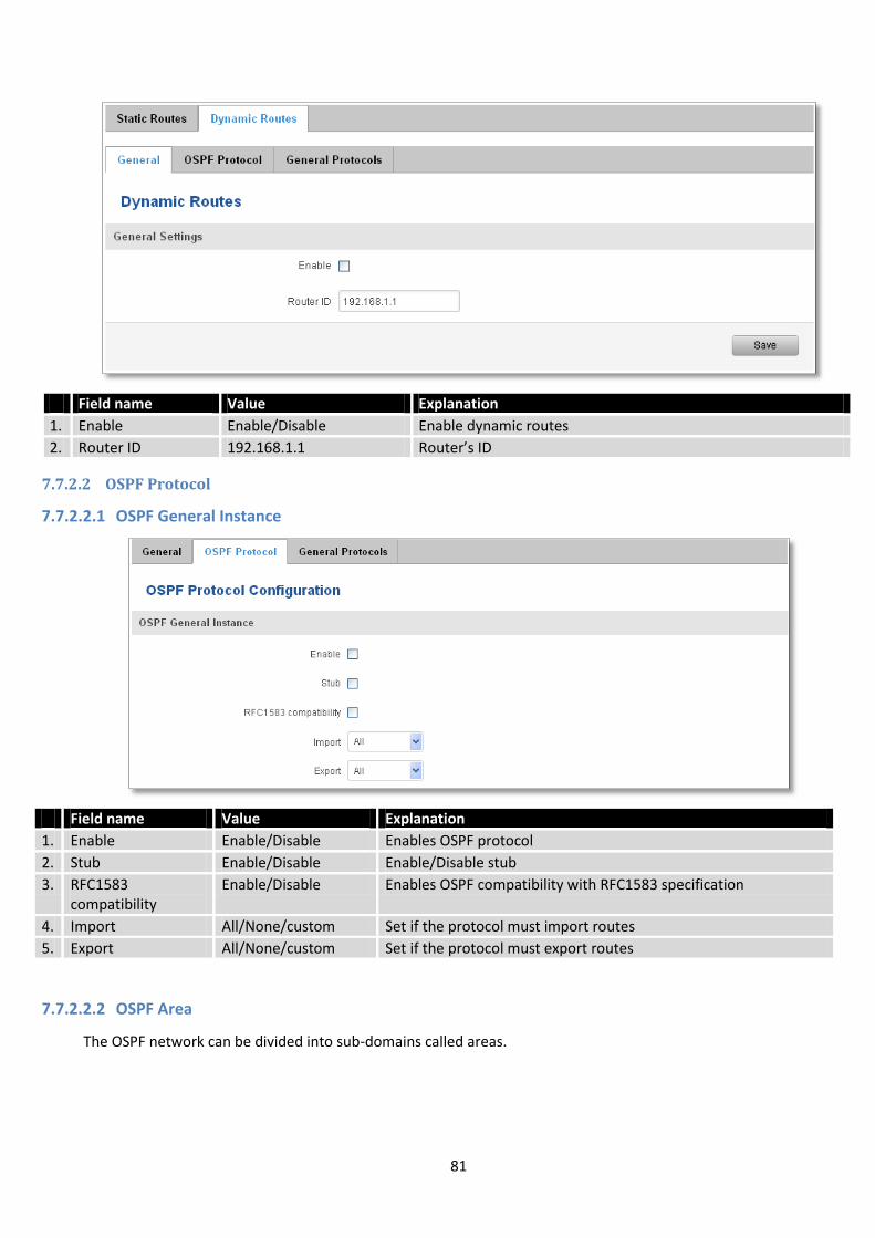
81
7.7.2.2 OSPF Protocol
7.7.2.2.1 OSPF General Instance
Field name Value Explanation
1. Enable Enable/Disable Enables OSPF protocol
2. Stub Enable/Disable Enable/Disable stub
3. RFC1583 compatibility
Enable/Disable Enables OSPF compatibility with RFC1583 specification
4. Import All/None/custom Set if the protocol must import routes
5. Export All/None/custom Set if the protocol must export routes
7.7.2.2.2 OSPF Area
The OSPF network can be divided into sub-domains called areas.
Field name Value Explanation
1. Enable Enable/Disable Enable dynamic routes
2. Router ID 192.168.1.1 Router’s ID
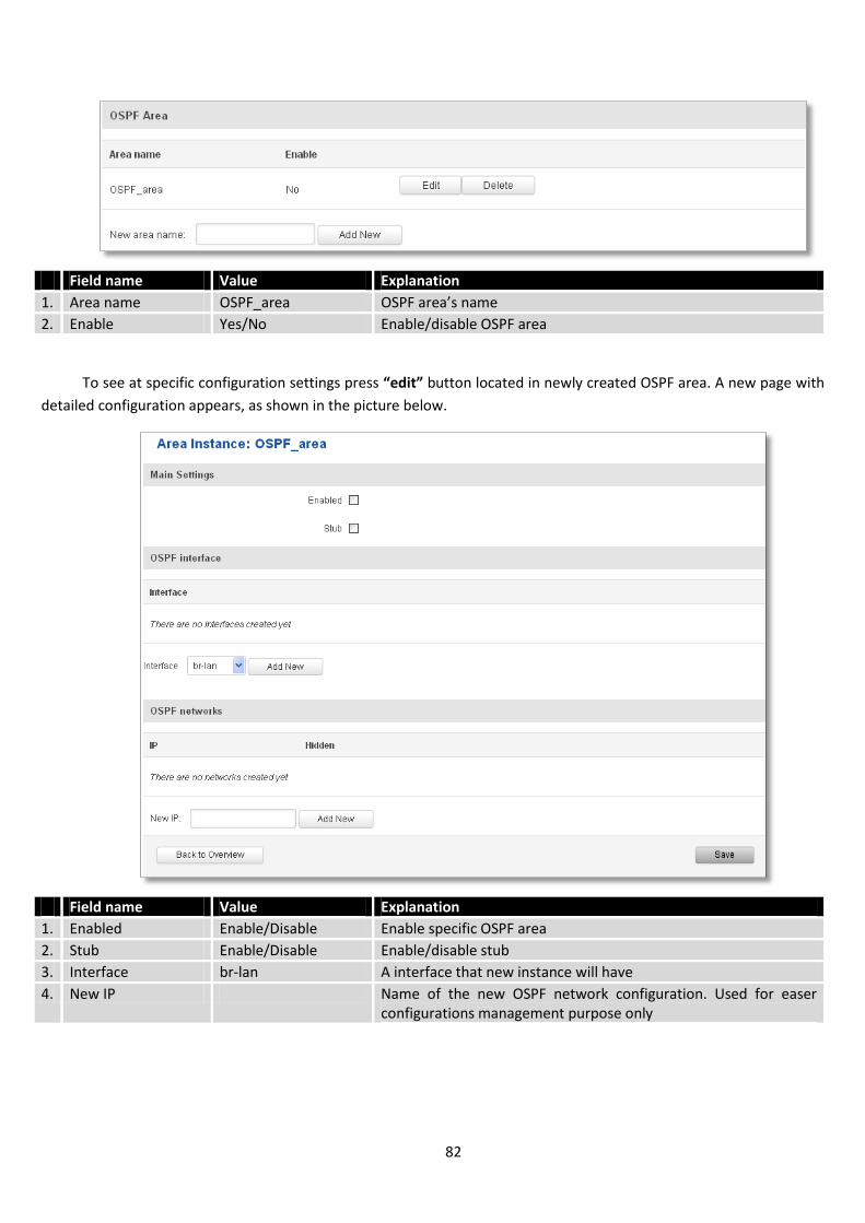
82
Field name Value Explanation
1. Area name OSPF_area OSPF area’s name
2. Enable Yes/No Enable/disable OSPF area
To see at specific configuration settings press “edit” button located in newly created OSPF area. A new page with
detailed configuration appears, as shown in the picture below.
Field name Value Explanation
1. Enabled Enable/Disable Enable specific OSPF area
2. Stub Enable/Disable Enable/disable stub
3. Interface br-lan A interface that new instance will have
4. New IP Name of the new OSPF network configuration. Used for easer configurations management purpose only
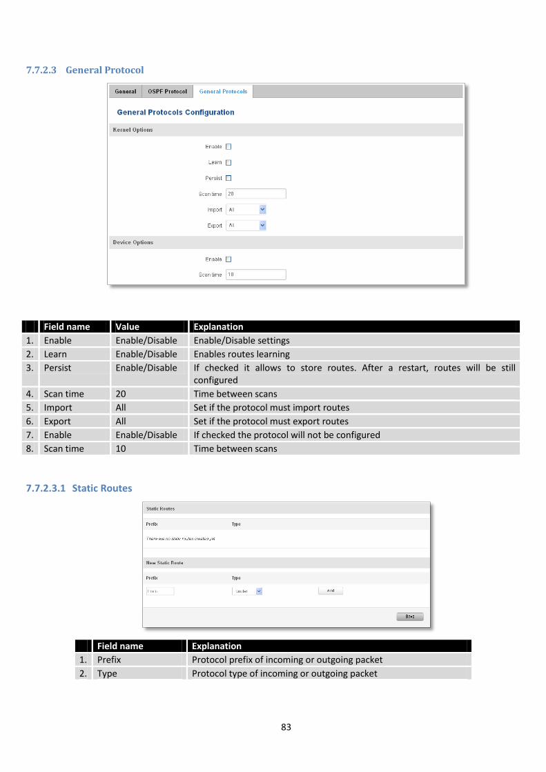
83
7.7.2.3 General Protocol
Field name Value Explanation
1. Enable Enable/Disable Enable/Disable settings
2. Learn Enable/Disable Enables routes learning
3. Persist Enable/Disable If checked it allows to store routes. After a restart, routes will be still configured
4. Scan time 20 Time between scans
5. Import All Set if the protocol must import routes
6. Export All Set if the protocol must export routes
7. Enable Enable/Disable If checked the protocol will not be configured
8. Scan time 10 Time between scans
7.7.2.3.1 Static Routes
Field name Explanation
1. Prefix Protocol prefix of incoming or outgoing packet
2. Type Protocol type of incoming or outgoing packet
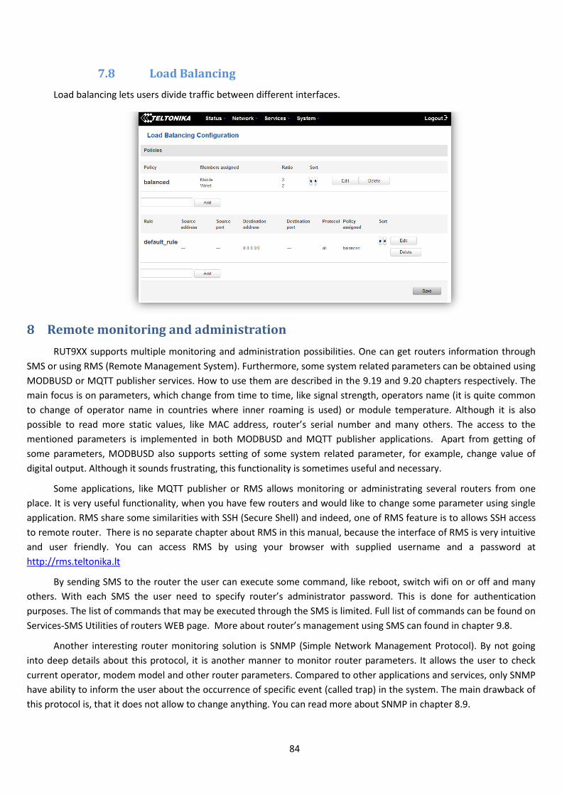
84
7.8 Load Balancing
Load balancing lets users divide traffic between different interfaces.
8 Remote monitoring and administration
RUT9XX supports multiple monitoring and administration possibilities. One can get routers information through
SMS or using RMS (Remote Management System). Furthermore, some system related parameters can be obtained using
MODBUSD or MQTT publisher services. How to use them are described in the 9.19 and 9.20 chapters respectively. The
main focus is on parameters, which change from time to time, like signal strength, operators name (it is quite common
to change of operator name in countries where inner roaming is used) or module temperature. Although it is also
possible to read more static values, like MAC address, router’s serial number and many others. The access to the
mentioned parameters is implemented in both MODBUSD and MQTT publisher applications. Apart from getting of
some parameters, MODBUSD also supports setting of some system related parameter, for example, change value of
digital output. Although it sounds frustrating, this functionality is sometimes useful and necessary.
Some applications, like MQTT publisher or RMS allows monitoring or administrating several routers from one
place. It is very useful functionality, when you have few routers and would like to change some parameter using single
application. RMS share some similarities with SSH (Secure Shell) and indeed, one of RMS feature is to allows SSH access
to remote router. There is no separate chapter about RMS in this manual, because the interface of RMS is very intuitive
and user friendly. You can access RMS by using your browser with supplied username and a password at
http://rms.teltonika.lt
By sending SMS to the router the user can execute some command, like reboot, switch wifi on or off and many
others. With each SMS the user need to specify router’s administrator password. This is done for authentication
purposes. The list of commands that may be executed through the SMS is limited. Full list of commands can be found on
Services-SMS Utilities of routers WEB page. More about router’s management using SMS can found in chapter 9.8.
Another interesting router monitoring solution is SNMP (Simple Network Management Protocol). By not going
into deep details about this protocol, it is another manner to monitor router parameters. It allows the user to check
current operator, modem model and other router parameters. Compared to other applications and services, only SNMP
have ability to inform the user about the occurrence of specific event (called trap) in the system. The main drawback of
this protocol is, that it does not allow to change anything. You can read more about SNMP in chapter 8.9.
85
Apart from services mentioned earlier, there is one service, which is used only for communication between router
and Android type device (phones, etc’). It is called json-rpc and allows to set or get various parameters of the system.
JSON-RPC can execute the same commands, like user through SSH. To sum up, this approach opens wide possibilities in
communication between router and Android. However, there is no separate topic about JSON-RPC in this manual,
because this type of communication is generally not for end-user use.
Each approach has its advantages and disadvantages. In some situations, maybe MQTT publisher works better
than MODBUSD, while in others, MODBUSD will be the better choice. The most versatile manner of system monitoring
and administration is through SSH. The SSH provides complete control of the router. The user can execute commands,
write shell scripts and do many other things. In such case, the user only needs application to connect router through
SSH. The most popular application used in Windows type operating systems is called Putty. If you try to connect to
router from Unix like operating system, you only need to execute ssh command with some arguments, like hostname
and username (in this case – root).
Sometimes the use of SSH is not necessary, so other more conservative services/applications are used. The
complete list of applications and services, which can be used for router administration and monitoring are given below.
It can be seen, that all applications, except MQTT publisher and SNMP supports setting/getting of some system related
parameter.
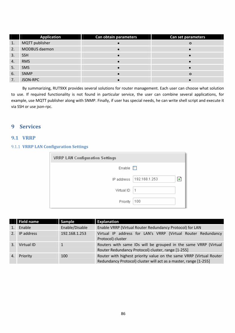
86
Application Can obtain parameters Can set parameters
1. MQTT publisher o
2. MODBUS daemon
3. SSH
4. RMS
5. SMS
6. SNMP o
7. JSON-RPC
By summarizing, RUT9XX provides several solutions for router management. Each user can choose what solution
to use. If required functionality is not found in particular service, the user can combine several applications, for
example, use MQTT publisher along with SNMP. Finally, if user has special needs, he can write shell script and execute it
via SSH or use json-rpc.
9 Services
9.1 VRRP
9.1.1 VRRP LAN Configuration Settings
Field name Sample Explanation
1. Enable Enable/Disable Enable VRRP (Virtual Router Redundancy Protocol) for LAN
2. IP address 192.168.1.253 Virtual IP address for LAN's VRRP (Virtual Router Redundancy Protocol) cluster
3. Virtual ID 1 Routers with same IDs will be grouped in the same VRRP (Virtual Router Redundancy Protocol) cluster, range [1-255]
4. Priority 100 Router with highest priority value on the same VRRP (Virtual Router Redundancy Protocol) cluster will act as a master, range [1-255]
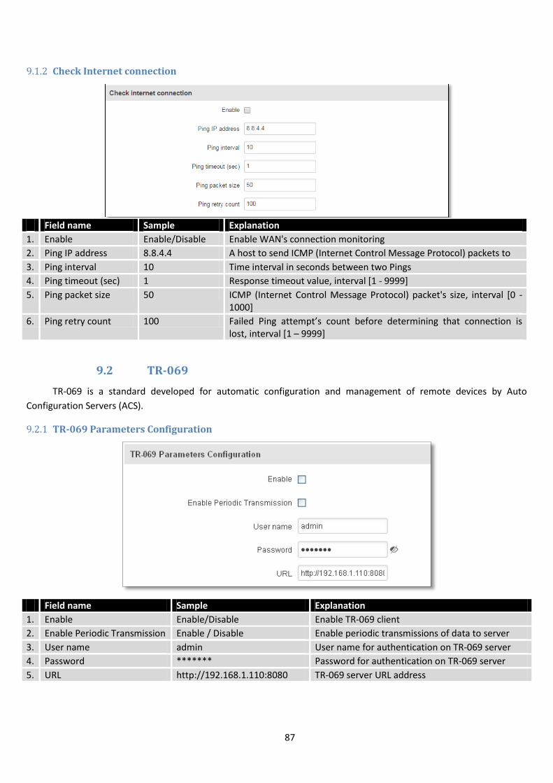
87
9.1.2 Check Internet connection
Field name Sample Explanation
1. Enable Enable/Disable Enable WAN's connection monitoring
2. Ping IP address 8.8.4.4 A host to send ICMP (Internet Control Message Protocol) packets to
3. Ping interval 10 Time interval in seconds between two Pings
4. Ping timeout (sec) 1 Response timeout value, interval [1 - 9999]
5. Ping packet size 50 ICMP (Internet Control Message Protocol) packet's size, interval [0 - 1000]
6. Ping retry count 100 Failed Ping attempt’s count before determining that connection is lost, interval [1 – 9999]
9.2 TR-069
TR-069 is a standard developed for automatic configuration and management of remote devices by Auto
Configuration Servers (ACS).
9.2.1 TR-069 Parameters Configuration
Field name Sample Explanation
1. Enable Enable/Disable Enable TR-069 client
2. Enable Periodic Transmission Enable / Disable Enable periodic transmissions of data to server
3. User name admin User name for authentication on TR-069 server
4. Password ******* Password for authentication on TR-069 server
5. URL http://192.168.1.110:8080 TR-069 server URL address
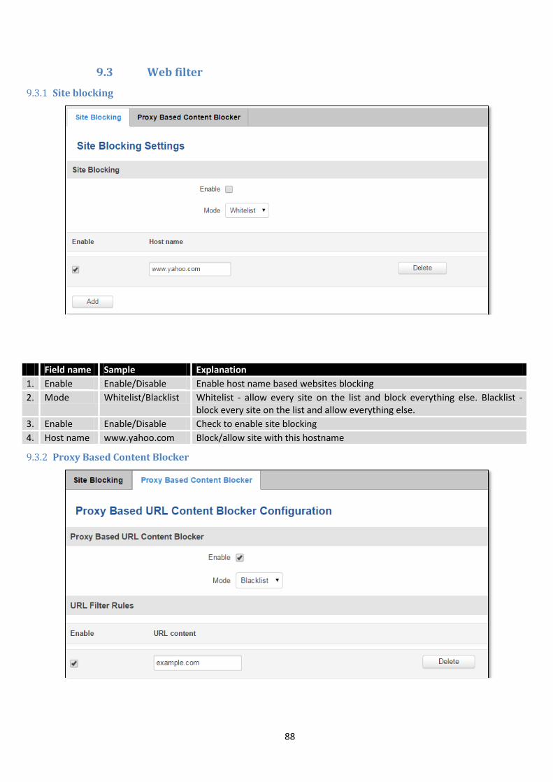
88
9.3 Web filter
9.3.1 Site blocking
Field name Sample Explanation
1. Enable Enable/Disable Enable host name based websites blocking
2. Mode Whitelist/Blacklist Whitelist - allow every site on the list and block everything else. Blacklist - block every site on the list and allow everything else.
3. Enable Enable/Disable Check to enable site blocking
4. Host name www.yahoo.com Block/allow site with this hostname
9.3.2 Proxy Based Content Blocker
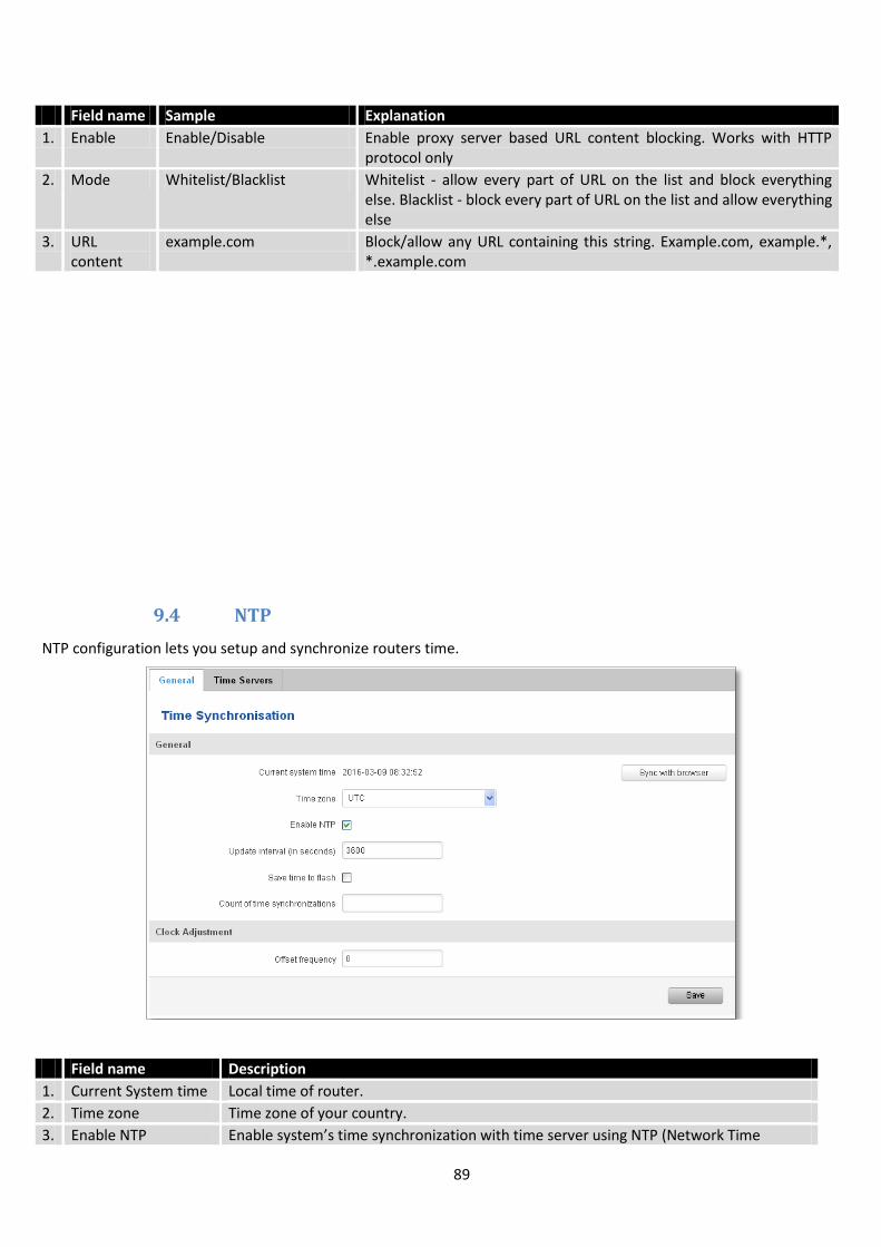
89
Field name Sample Explanation
1. Enable Enable/Disable Enable proxy server based URL content blocking. Works with HTTP protocol only
2. Mode Whitelist/Blacklist Whitelist - allow every part of URL on the list and block everything else. Blacklist - block every part of URL on the list and allow everything else
3. URL content
example.com Block/allow any URL containing this string. Example.com, example.*, *.example.com
9.4 NTP
NTP configuration lets you setup and synchronize routers time.
Field name Description
1. Current System time Local time of router.
2. Time zone Time zone of your country.
3. Enable NTP Enable system’s time synchronization with time server using NTP (Network Time

90
Protocol)
4. Update interval How often router updates systems time
5. Save time to flash Save last synchronized time to flash memory
6. Count of time synchronizations
Total amount of times that router will do the synchronization. Note: If left blank - the count will be infinite
7. Offset frequency Adjust the minor drift of the clock so that it will be more accurate
Note, that under Time Servers at least one server has to be present, otherwise NTP will not serve its purposes.

91
9.5 RS232/RS485
RS232 and RS485 functions are designed to utilize available serial interfaces of the router. Serial interfaces
provide possibility for legacy devices to gain access to IP networks.
9.5.1 RS232
Field name Sample Explanation
1. Enabled Enable/Disable Check the box to enable the serial port function.
2. Baud rate 300 / 115200 Select the communication speed of the serial interface.
3. Data bits 5 - 8 Specifies how many bits will be used for character
4. Parity None / Odd / Even Select the parity bit setting used for error detection during data transfer.
5. Stop bits 1 / 2 Specifies how many stop bits will be used to detect the end of character
6. Flow control None / RTS- CTS / Xon-Xoff Specifies what kind of characters to use for flow control
7. Serial type Console / Over IP / Modem / Modbus Gateway
Specifies function of serial interface
8. Interface LAN/ WAN/ VPN Interface used for connection
9. Allow IP 192.168.1.102 Allow IP connecting to server
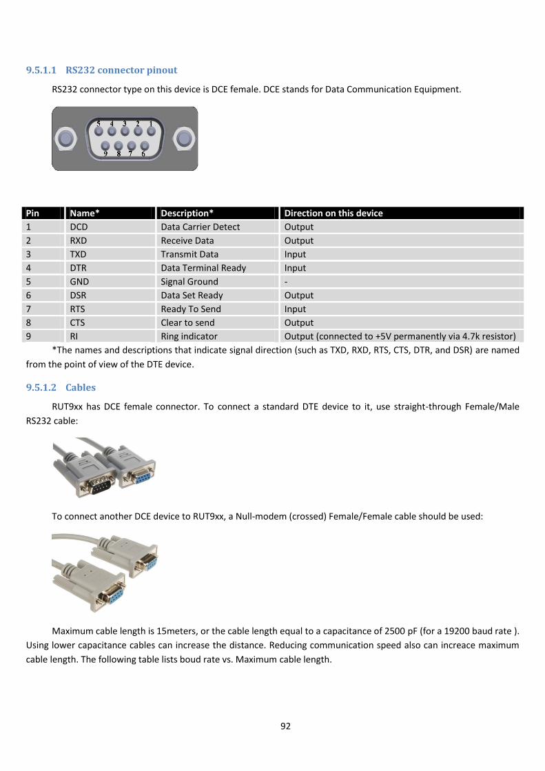
92
9.5.1.1 RS232 connector pinout
RS232 connector type on this device is DCE female. DCE stands for Data Communication Equipment.
Pin Name* Description* Direction on this device
1 DCD Data Carrier Detect Output
2 RXD Receive Data Output
3 TXD Transmit Data Input
4 DTR Data Terminal Ready Input
5 GND Signal Ground -
6 DSR Data Set Ready Output
7 RTS Ready To Send Input
8 CTS Clear to send Output
9 RI Ring indicator Output (connected to +5V permanently via 4.7k resistor)
*The names and descriptions that indicate signal direction (such as TXD, RXD, RTS, CTS, DTR, and DSR) are named
from the point of view of the DTE device.
9.5.1.2 Cables
RUT9xx has DCE female connector. To connect a standard DTE device to it, use straight-through Female/Male
RS232 cable:
To connect another DCE device to RUT9xx, a Null-modem (crossed) Female/Female cable should be used:
Maximum cable length is 15meters, or the cable length equal to a capacitance of 2500·pF (for a 19200 baud rate ).
Using lower capacitance cables can increase the distance. Reducing communication speed also can increace maximum
cable length. The following table lists boud rate vs. Maximum cable length.
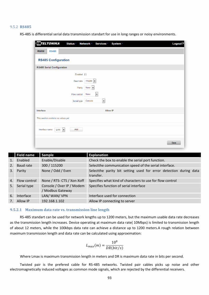
93
9.5.2 RS485
RS-485 is differential serial data transmission standart for use in long ranges or noisy environments.
Field name Sample Explanation
1. Enabled Enable/Disable Check the box to enable the serial port function.
2. Baud rate 300 / 115200 Selectthe communication speed of the serial interface.
3. Parity None / Odd / Even Selectthe parity bit setting used for error detection during data transfer.
4. Flow control None / RTS- CTS / Xon-Xoff Specifies what kind of characters to use for flow control
5. Serial type Console / Over IP / Modem / Modbus Gateway
Specifies function of serial interface
6. Interface LAN/ WAN/ VPN Interface used for connection
7. Allow IP 192.168.1.102 Allow IP connecting to server
9.5.2.1 Maximum data rate vs. transmission line length
RS-485 standart can be used for network lengths up to 1200 meters, but the maximum usable data rate decreases
as the transmission length increases. Device operating at maximum data rate( 10Mbps) is limited to transmission length
of about 12 meters, while the 100kbps data rate can achieve a distance up to 1200 meters.A rough relation between
maximum transmission length and data rate can be calculated using approximation:
( )
( ⁄ )
Where Lmax is maximum transmission length in meters and DR is maximum data rate in bits per second.
Twisted pair is the prefered cable for RS-485 networks. Twisted pair cables picks up noise and other electromagnetically induced voltages as common mode signals, which are rejected by the differential receivers.

94
9.5.2.2 Cable type
Recomended cable parameters:
Parameter Value
Cable Type 22-24 AWG, 2 – pair (used for full-duplex networks ) or 1-pair (used for half duplex networks). One addtitional wire for ground connection is needed.
Characteristic cable Impedance 120 Ω @ 1MHz
Capacitance (conductor to conductor) 36 pF/m
Propagation Velocity 78% (1.3 ns/ft)
9.5.2.3 RS485 connector pin-out
Name Description Type
D_P Driver positive signal Differential Output
D_N Driver negative signal Differential Output
R_P Receiver positive signal Differential input
R_N Receiver negative signal Differential input
Ground Device ground Differential Output
9.5.2.4 2-Wire and 4-Wire Networks
Below is an example of 4- wire network electrical connection. There are 3 devices shown in the example. One of the devices is master and other two- slaves. Termination resistors are placed at each cable end. Four-wire networks consists of one „master“ with its transmitter connected to each of the “slave” receivers on one twisted pair. The“slave” transmitters are all connected to the “master” receiver on a second twisted pair.
D_P R_P N/C
D_N R_N Ground
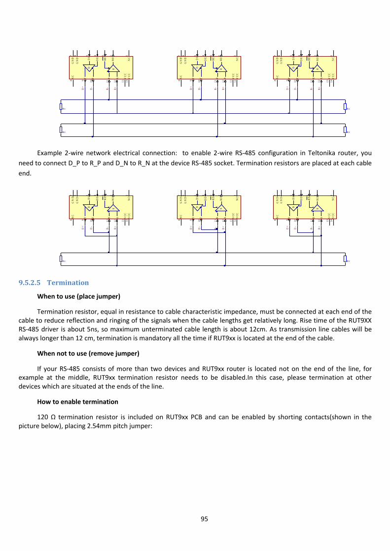
95
Example 2-wire network electrical connection: to enable 2-wire RS-485 configuration in Teltonika router, you
need to connect D_P to R_P and D_N to R_N at the device RS-485 socket. Termination resistors are placed at each cable
end.
9.5.2.5 Termination
When to use (place jumper)
Termination resistor, equal in resistance to cable characteristic impedance, must be connected at each end of the cable to reduce reflection and ringing of the signals when the cable lengths get relatively long. Rise time of the RUT9XX RS-485 driver is about 5ns, so maximum unterminated cable length is about 12cm. As transmission line cables will be always longer than 12 cm, termination is mandatory all the time if RUT9xx is located at the end of the cable.
When not to use (remove jumper)
If your RS-485 consists of more than two devices and RUT9xx router is located not on the end of the line, for example at the middle, RUT9xx termination resistor needs to be disabled.In this case, please termination at other devices which are situated at the ends of the line.
How to enable termination
120 Ω termination resistor is included on RUT9xx PCB and can be enabled by shorting contacts(shown in the picture below), placing 2.54mm pitch jumper:
VC
C1
3
RO
2
DI
5
GN
D6
Y9
Z1
0
B1
1
A1
2R
D
GN
D7
RE
3
DE
4
NC
1
NC
8
VC
C1
4
VC
C1
3
RO
2
DI
5
GN
D6
Y9
Z1
0
B1
1
A1
2R
D
GN
D7
RE
3
DE
4
NC
1
NC
8
VC
C1
4
VC
C1
3
RO
2
DI
5
GN
D6
Y9
Z1
0
B1
1
A1
2R
D
GN
D7
RE
3
DE
4
NC
1
NC
8
VC
C1
4
D+
D-
R-
R+
R t
R t
R t
R t
D+
D-
R-
R+
D+
D-
R-
R+
VC
C1
3
RO
2
DI
5
GN
D6
Y9
Z1
0
B1
1
A1
2R
D
GN
D7
RE
3
DE
4
NC
1
NC
8
VC
C1
4
VC
C1
3
RO
2
DI
5
GN
D6
Y9
Z1
0
B1
1
A1
2R
D
GN
D7
RE
3
DE
4
NC
1
NC
8
VC
C1
4
VC
C1
3
RO
2
DI
5
GN
D6
Y9
Z1
0
B1
1
A1
2R
D
GN
D7
RE
3
DE
4
NC
1
NC
8
VC
C1
4
D+
D-
R-
R+
R t R t
D+
D-
R-
R+
D+
D-
R-
R+
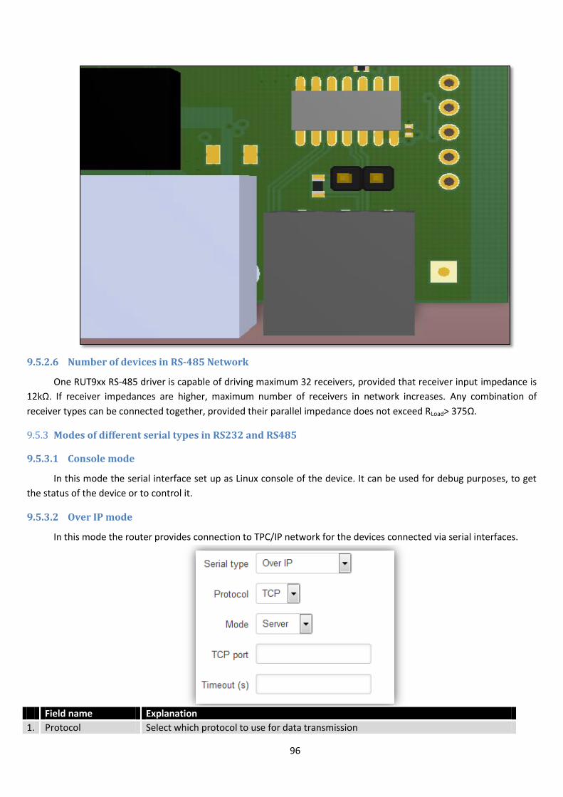
96
9.5.2.6 Number of devices in RS-485 Network
One RUT9xx RS-485 driver is capable of driving maximum 32 receivers, provided that receiver input impedance is
12kΩ. If receiver impedances are higher, maximum number of receivers in network increases. Any combination of
receiver types can be connected together, provided their parallel impedance does not exceed RLoad> 375Ω.
9.5.3 Modes of different serial types in RS232 and RS485
9.5.3.1 Console mode
In this mode the serial interface set up as Linux console of the device. It can be used for debug purposes, to get
the status of the device or to control it.
9.5.3.2 Over IP mode
In this mode the router provides connection to TPC/IP network for the devices connected via serial interfaces.
Field name Explanation
1. Protocol Select which protocol to use for data transmission
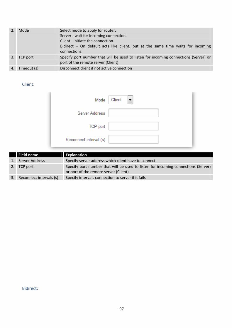
97
2. Mode Select mode to apply for router. Server - wait for incoming connection. Client - initiate the connection. Bidirect – On default acts like client, but at the same time waits for incoming connections.
3. TCP port Specify port number that will be used to listen for incoming connections (Server) or port of the remote server (Client)
4. Timeout (s) Disconnect client if not active connection
Client:
Field name Explanation
1. Server Address Specify server address which client have to connect
2. TCP port Specify port number that will be used to listen for incoming connections (Server) or port of the remote server (Client)
3. Reconnect intervals (s) Specify intervals connection to server if it fails
Bidirect:
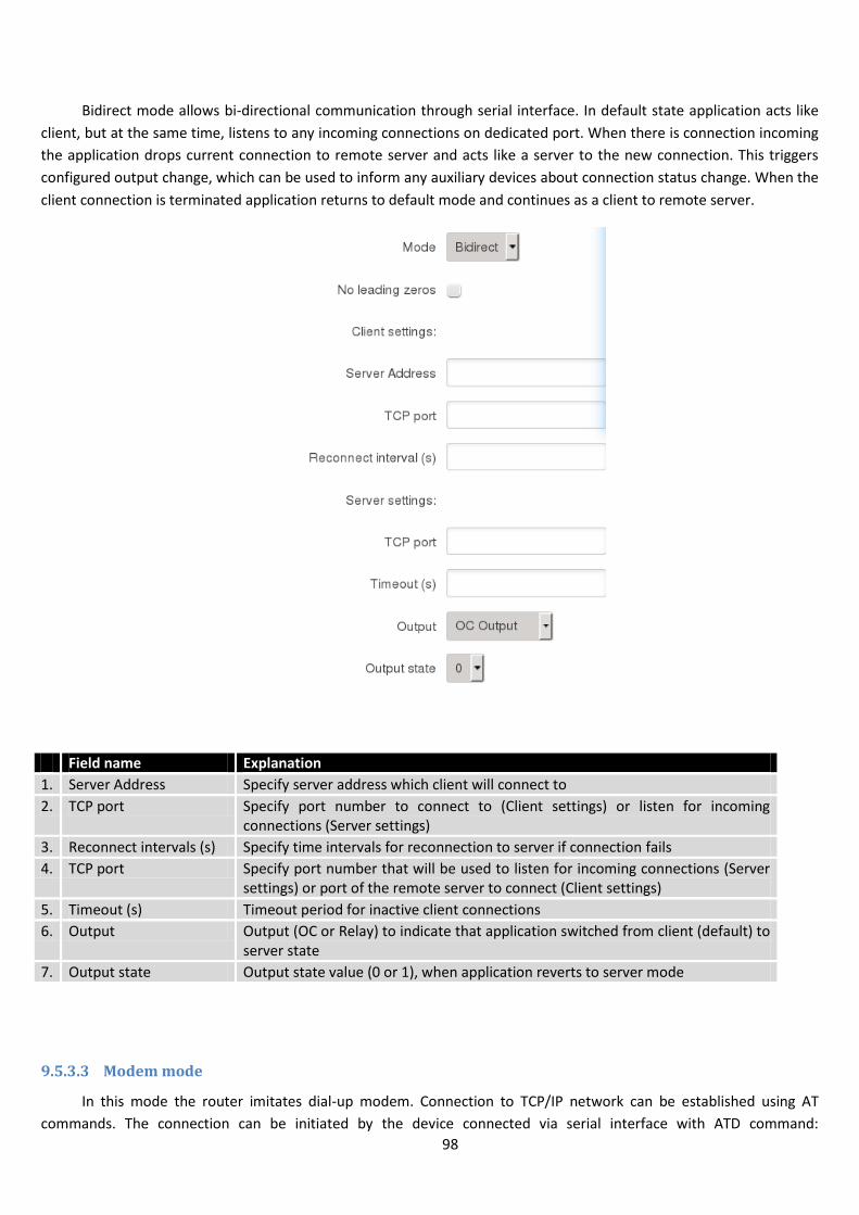
98
Bidirect mode allows bi-directional communication through serial interface. In default state application acts like
client, but at the same time, listens to any incoming connections on dedicated port. When there is connection incoming
the application drops current connection to remote server and acts like a server to the new connection. This triggers
configured output change, which can be used to inform any auxiliary devices about connection status change. When the
client connection is terminated application returns to default mode and continues as a client to remote server.
Field name Explanation
1. Server Address Specify server address which client will connect to
2. TCP port Specify port number to connect to (Client settings) or listen for incoming connections (Server settings)
3. Reconnect intervals (s) Specify time intervals for reconnection to server if connection fails
4. TCP port Specify port number that will be used to listen for incoming connections (Server settings) or port of the remote server to connect (Client settings)
5. Timeout (s) Timeout period for inactive client connections
6. Output Output (OC or Relay) to indicate that application switched from client (default) to server state
7. Output state Output state value (0 or 1), when application reverts to server mode
9.5.3.3 Modem mode
In this mode the router imitates dial-up modem. Connection to TCP/IP network can be established using AT
commands. The connection can be initiated by the device connected via serial interface with ATD command:
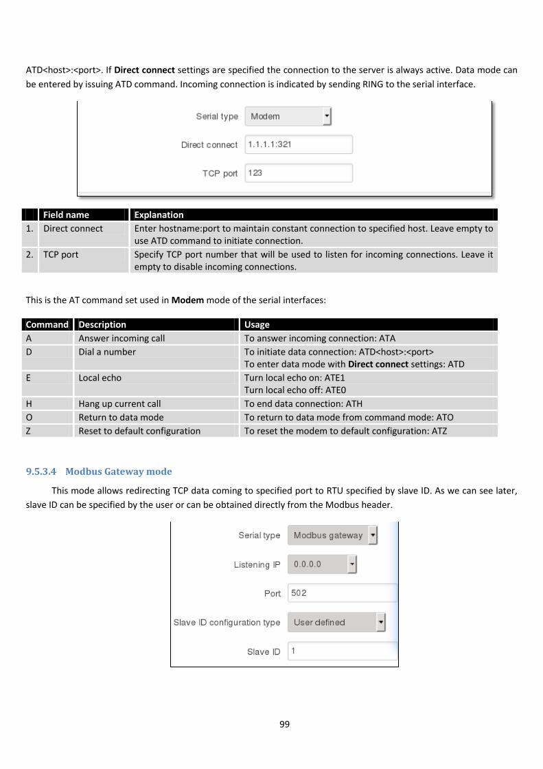
99
ATD<host>:<port>. If Direct connect settings are specified the connection to the server is always active. Data mode can
be entered by issuing ATD command. Incoming connection is indicated by sending RING to the serial interface.
Field name Explanation
1. Direct connect Enter hostname:port to maintain constant connection to specified host. Leave empty to use ATD command to initiate connection.
2. TCP port Specify TCP port number that will be used to listen for incoming connections. Leave it empty to disable incoming connections.
This is the AT command set used in Modem mode of the serial interfaces:
Command Description Usage
A Answer incoming call To answer incoming connection: ATA
D Dial a number To initiate data connection: ATD<host>:<port> To enter data mode with Direct connect settings: ATD
E Local echo Turn local echo on: ATE1 Turn local echo off: ATE0
H Hang up current call To end data connection: ATH
O Return to data mode To return to data mode from command mode: ATO
Z Reset to default configuration To reset the modem to default configuration: ATZ
9.5.3.4 Modbus Gateway mode
This mode allows redirecting TCP data coming to specified port to RTU specified by slave ID. As we can see later,
slave ID can be specified by the user or can be obtained directly from the Modbus header.
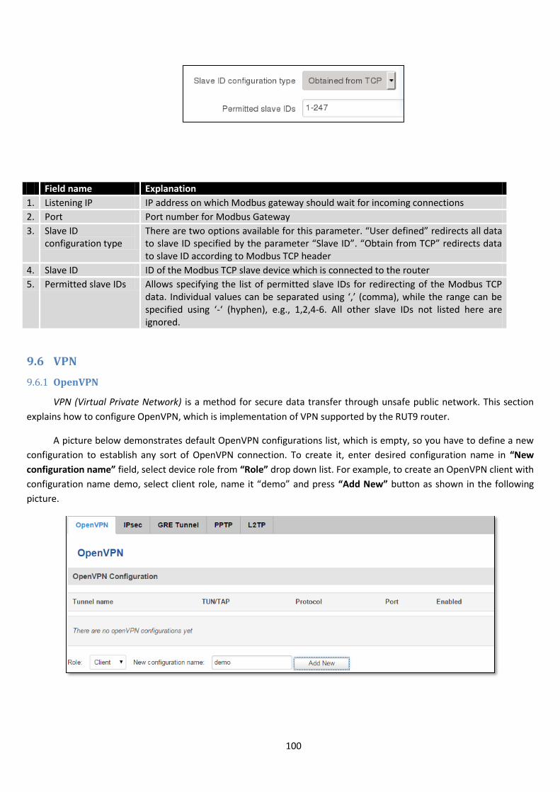
100
Field name Explanation
1. Listening IP IP address on which Modbus gateway should wait for incoming connections
2. Port Port number for Modbus Gateway
3. Slave ID configuration type
There are two options available for this parameter. “User defined” redirects all data to slave ID specified by the parameter “Slave ID”. “Obtain from TCP” redirects data to slave ID according to Modbus TCP header
4. Slave ID ID of the Modbus TCP slave device which is connected to the router
5. Permitted slave IDs Allows specifying the list of permitted slave IDs for redirecting of the Modbus TCP data. Individual values can be separated using ‘,’ (comma), while the range can be specified using ‘-‘ (hyphen), e.g., 1,2,4-6. All other slave IDs not listed here are ignored.
9.6 VPN
9.6.1 OpenVPN
VPN (Virtual Private Network) is a method for secure data transfer through unsafe public network. This section
explains how to configure OpenVPN, which is implementation of VPN supported by the RUT9 router.
A picture below demonstrates default OpenVPN configurations list, which is empty, so you have to define a new
configuration to establish any sort of OpenVPN connection. To create it, enter desired configuration name in “New
configuration name” field, select device role from “Role” drop down list. For example, to create an OpenVPN client with
configuration name demo, select client role, name it “demo” and press “Add New” button as shown in the following
picture.

101
To see at specific configuration settings press “edit” button located in newly created configuration entry. A new
page with detailed configuration appears, as shown in the picture below (TLS client example).
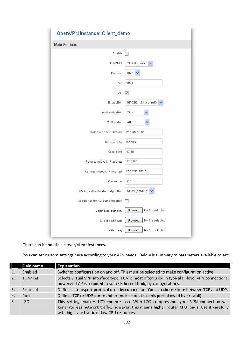
102
There can be multiple server/client instances.
You can set custom settings here according to your VPN needs. Below is summary of parameters available to set:
Field name Explanation
1. Enabled Switches configuration on and off. This must be selected to make configuration active.
2. TUN/TAP Selects virtual VPN interface type. TUN is most often used in typical IP-level VPN connections, however, TAP is required to some Ethernet bridging configurations.
3. Protocol Defines a transport protocol used by connection. You can choose here between TCP and UDP.
4. Port Defines TCP or UDP port number (make sure, that this port allowed by firewall).
5. LZO This setting enables LZO compression. With LZO compression, your VPN connection will generate less network traffic; however, this means higher router CPU loads. Use it carefully with high rate traffic or low CPU resources.
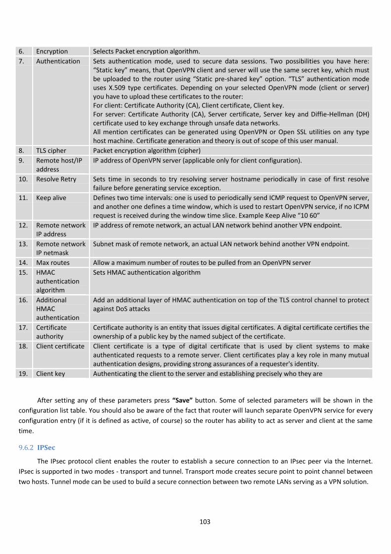
103
6. Encryption Selects Packet encryption algorithm.
7. Authentication Sets authentication mode, used to secure data sessions. Two possibilities you have here: “Static key” means, that OpenVPN client and server will use the same secret key, which must be uploaded to the router using “Static pre-shared key” option. “TLS” authentication mode uses X.509 type certificates. Depending on your selected OpenVPN mode (client or server) you have to upload these certificates to the router: For client: Certificate Authority (CA), Client certificate, Client key. For server: Certificate Authority (CA), Server certificate, Server key and Diffie-Hellman (DH) certificate used to key exchange through unsafe data networks. All mention certificates can be generated using OpenVPN or Open SSL utilities on any type host machine. Certificate generation and theory is out of scope of this user manual.
8. TLS cipher Packet encryption algorithm (cipher)
9. Remote host/IP address
IP address of OpenVPN server (applicable only for client configuration).
10. Resolve Retry Sets time in seconds to try resolving server hostname periodically in case of first resolve failure before generating service exception.
11. Keep alive Defines two time intervals: one is used to periodically send ICMP request to OpenVPN server, and another one defines a time window, which is used to restart OpenVPN service, if no ICPM request is received during the window time slice. Example Keep Alive “10 60”
12. Remote network IP address
IP address of remote network, an actual LAN network behind another VPN endpoint.
13. Remote network IP netmask
Subnet mask of remote network, an actual LAN network behind another VPN endpoint.
14. Max routes Allow a maximum number of routes to be pulled from an OpenVPN server
15. HMAC authentication algorithm
Sets HMAC authentication algorithm
16. Additional HMAC authentication
Add an additional layer of HMAC authentication on top of the TLS control channel to protect against DoS attacks
17. Certificate authority
Certificate authority is an entity that issues digital certificates. A digital certificate certifies the ownership of a public key by the named subject of the certificate.
18. Client certificate Client certificate is a type of digital certificate that is used by client systems to make authenticated requests to a remote server. Client certificates play a key role in many mutual authentication designs, providing strong assurances of a requester's identity.
19. Client key Authenticating the client to the server and establishing precisely who they are
After setting any of these parameters press “Save” button. Some of selected parameters will be shown in the
configuration list table. You should also be aware of the fact that router will launch separate OpenVPN service for every
configuration entry (if it is defined as active, of course) so the router has ability to act as server and client at the same
time.
9.6.2 IPSec
The IPsec protocol client enables the router to establish a secure connection to an IPsec peer via the Internet.
IPsec is supported in two modes - transport and tunnel. Transport mode creates secure point to point channel between
two hosts. Tunnel mode can be used to build a secure connection between two remote LANs serving as a VPN solution.
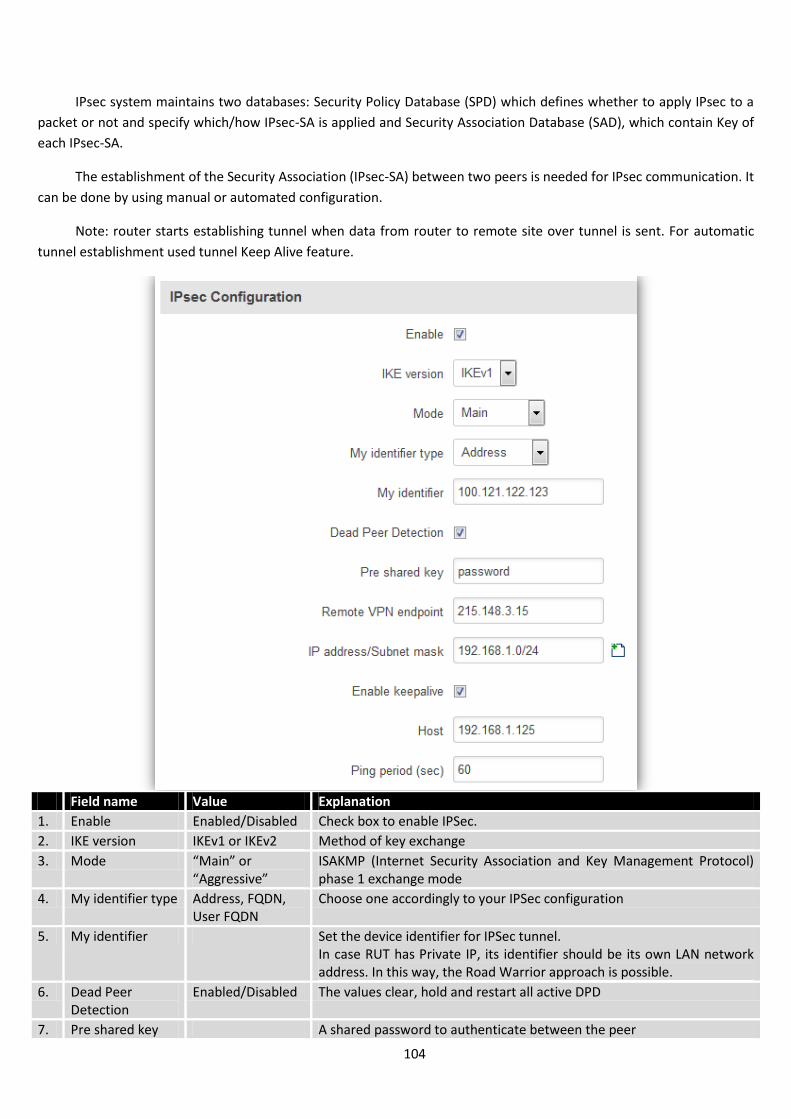
104
IPsec system maintains two databases: Security Policy Database (SPD) which defines whether to apply IPsec to a
packet or not and specify which/how IPsec-SA is applied and Security Association Database (SAD), which contain Key of
each IPsec-SA.
The establishment of the Security Association (IPsec-SA) between two peers is needed for IPsec communication. It
can be done by using manual or automated configuration.
Note: router starts establishing tunnel when data from router to remote site over tunnel is sent. For automatic
tunnel establishment used tunnel Keep Alive feature.
Field name Value Explanation
1. Enable Enabled/Disabled Check box to enable IPSec.
2. IKE version IKEv1 or IKEv2 Method of key exchange
3. Mode “Main” or “Aggressive”
ISAKMP (Internet Security Association and Key Management Protocol) phase 1 exchange mode
4. My identifier type Address, FQDN, User FQDN
Choose one accordingly to your IPSec configuration
5. My identifier Set the device identifier for IPSec tunnel. In case RUT has Private IP, its identifier should be its own LAN network address. In this way, the Road Warrior approach is possible.
6. Dead Peer Detection
Enabled/Disabled The values clear, hold and restart all active DPD
7. Pre shared key A shared password to authenticate between the peer
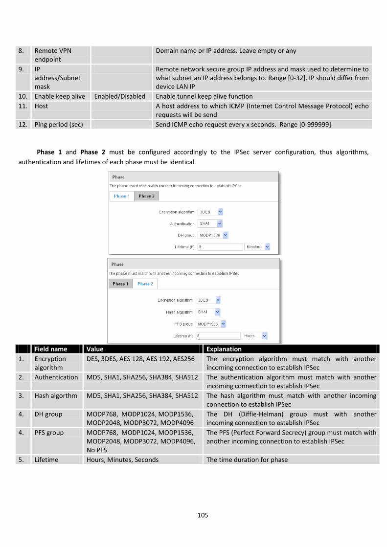
105
8. Remote VPN endpoint
Domain name or IP address. Leave empty or any
9. IP address/Subnet mask
Remote network secure group IP address and mask used to determine to what subnet an IP address belongs to. Range [0-32]. IP should differ from device LAN IP
10. Enable keep alive Enabled/Disabled Enable tunnel keep alive function
11. Host A host address to which ICMP (Internet Control Message Protocol) echo requests will be send
12. Ping period (sec) Send ICMP echo request every x seconds. Range [0-999999]
Phase 1 and Phase 2 must be configured accordingly to the IPSec server configuration, thus algorithms,
authentication and lifetimes of each phase must be identical.
Field name Value Explanation
1. Encryption algorithm
DES, 3DES, AES 128, AES 192, AES256 The encryption algorithm must match with another incoming connection to establish IPSec
2. Authentication MD5, SHA1, SHA256, SHA384, SHA512 The authentication algorithm must match with another incoming connection to establish IPSec
3. Hash algorthm MD5, SHA1, SHA256, SHA384, SHA512 The hash algorithm must match with another incoming connection to establish IPSec
4. DH group MODP768, MODP1024, MODP1536, MODP2048, MODP3072, MODP4096
The DH (Diffie-Helman) group must with another incoming connection to establish IPSec
4. PFS group MODP768, MODP1024, MODP1536, MODP2048, MODP3072, MODP4096, No PFS
The PFS (Perfect Forward Secrecy) group must match with another incoming connection to establish IPSec
5. Lifetime Hours, Minutes, Seconds The time duration for phase

106
9.6.3 GRE Tunnel
GRE (Generic Routing Encapsulation RFC2784) is a solution for tunneling RFC1812 private address-space traffic
over an intermediate TCP/IP network such as the Internet. GRE tunneling does not use encryption it simply encapsulates
data and sends it over the WAN.
In the example network diagram two distant networks LAN1 and LAN2 are connected.
To create GRE tunnel the user must know the following parameters:
1. Source and destination IP addresses.
2. Tunnel local IP address
3. Distant network IP address and Subnet mask.
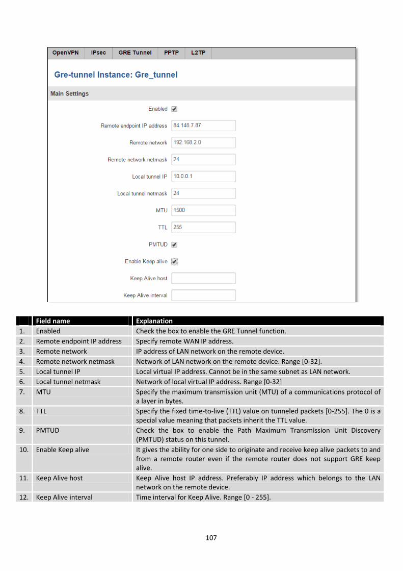
107
Field name Explanation
1. Enabled Check the box to enable the GRE Tunnel function.
2. Remote endpoint IP address Specify remote WAN IP address.
3. Remote network IP address of LAN network on the remote device.
4. Remote network netmask Network of LAN network on the remote device. Range [0-32].
5. Local tunnel IP Local virtual IP address. Cannot be in the same subnet as LAN network.
6. Local tunnel netmask Network of local virtual IP address. Range [0-32]
7. MTU Specify the maximum transmission unit (MTU) of a communications protocol of a layer in bytes.
8. TTL Specify the fixed time-to-live (TTL) value on tunneled packets [0-255]. The 0 is a special value meaning that packets inherit the TTL value.
9. PMTUD Check the box to enable the Path Maximum Transmission Unit Discovery (PMTUD) status on this tunnel.
10. Enable Keep alive It gives the ability for one side to originate and receive keep alive packets to and from a remote router even if the remote router does not support GRE keep alive.
11. Keep Alive host Keep Alive host IP address. Preferably IP address which belongs to the LAN network on the remote device.
12. Keep Alive interval Time interval for Keep Alive. Range [0 - 255].
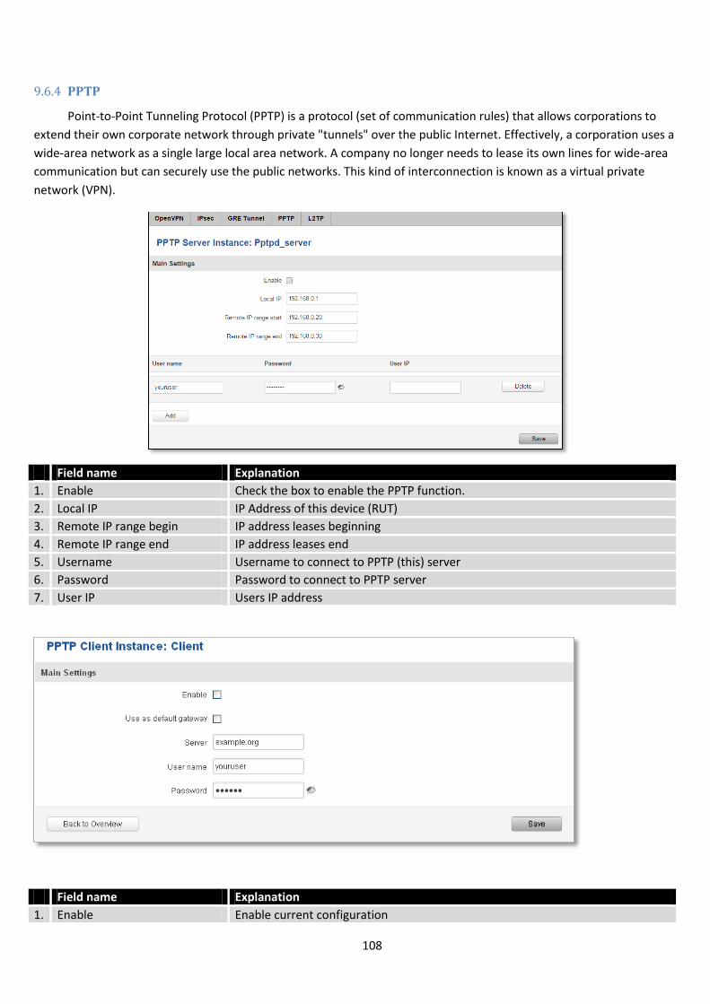
108
9.6.4 PPTP
Point-to-Point Tunneling Protocol (PPTP) is a protocol (set of communication rules) that allows corporations to
extend their own corporate network through private "tunnels" over the public Internet. Effectively, a corporation uses a
wide-area network as a single large local area network. A company no longer needs to lease its own lines for wide-area
communication but can securely use the public networks. This kind of interconnection is known as a virtual private
network (VPN).
Field name Explanation
1. Enable Check the box to enable the PPTP function.
2. Local IP IP Address of this device (RUT)
3. Remote IP range begin IP address leases beginning
4. Remote IP range end IP address leases end
5. Username Username to connect to PPTP (this) server
6. Password Password to connect to PPTP server
7. User IP Users IP address
Field name Explanation
1. Enable Enable current configuration
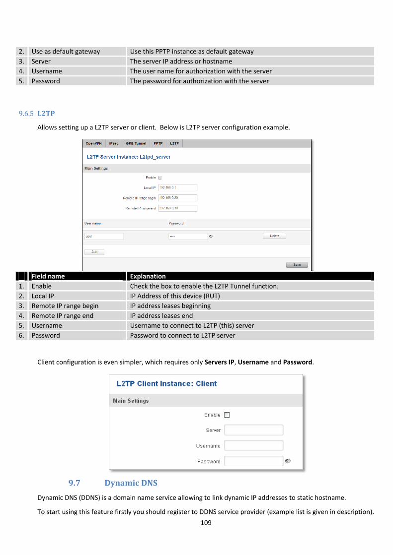
109
2. Use as default gateway Use this PPTP instance as default gateway
3. Server The server IP address or hostname
4. Username The user name for authorization with the server
5. Password The password for authorization with the server
9.6.5 L2TP
Allows setting up a L2TP server or client. Below is L2TP server configuration example.
Field name Explanation
1. Enable Check the box to enable the L2TP Tunnel function.
2. Local IP IP Address of this device (RUT)
3. Remote IP range begin IP address leases beginning
4. Remote IP range end IP address leases end
5. Username Username to connect to L2TP (this) server
6. Password Password to connect to L2TP server
Client configuration is even simpler, which requires only Servers IP, Username and Password.
9.7 Dynamic DNS
Dynamic DNS (DDNS) is a domain name service allowing to link dynamic IP addresses to static hostname.
To start using this feature firstly you should register to DDNS service provider (example list is given in description).

110
You are provided with add/delete buttons to manage and use different DDNS configurations at the same time!
You can configure many different DDNS Hostnames in the main DDNS Configuration section.
To edit your selected configuration, hit Edit.
Field name Value Explanation
1. Enable Enable/Disable Enables current DDNS configuration.
2. Status Timestamp of the last IP check or update.
3. Service 1. dydns.org 2. 3322.org 3. no-ip.com 4. easydns.com 5. zoneedit.com
Your dynamic DNS service provider selected from the list. In case your DDNS provider is not present from the ones provided, please feel free to use "custom" and add hostname of the update URL.
4. Hostname yourhost.example.org Domain name which will be linked with dynamic IP address.
5. Username your_username Name of the user account.
6. Password your_password Password of the user account.
7. IP Source Public Private Custom
This option allows you to select specific RUT interface, and then send the IP address of that interface to DDNS server. So if, for example, your RUT has Private IP (i.e. 10.140.56.57) on its WAN (3G interface), then you can send this exact IP to DDNS server by selecting "Private", or by selecting "Custom" and "WAN" interface. The DDNS server will then resolve hostname queries to this specific IP.
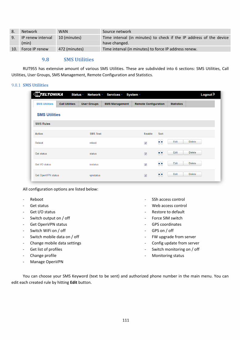
111
8. Network WAN Source network
9. IP renew interval (min)
10 (minutes) Time interval (in minutes) to check if the IP address of the device have changed.
10. Force IP renew 472 (minutes) Time interval (in minutes) to force IP address renew.
9.8 SMS Utilities
RUT955 has extensive amount of various SMS Utilities. These are subdivided into 6 sections: SMS Utilities, Call
Utilities, User Groups, SMS Management, Remote Configuration and Statistics.
9.8.1 SMS Utilities
All configuration options are listed below:
- Reboot
- Get status
- Get I/O status
- Switch output on / off
- Get OpenVPN status
- Switch WiFi on / off
- Switch mobile data on / off
- Change mobile data settings
- Get list of profiles
- Change profile
- Manage OpenVPN
- SSh access control
- Web access control
- Restore to default
- Force SIM switch
- GPS coordinates
- GPS on / off
- FW upgrade from server
- Config update from server
- Switch monitoring on / off
- Monitoring status
You can choose your SMS Keyword (text to be sent) and authorized phone number in the main menu. You can
edit each created rule by hitting Edit button.
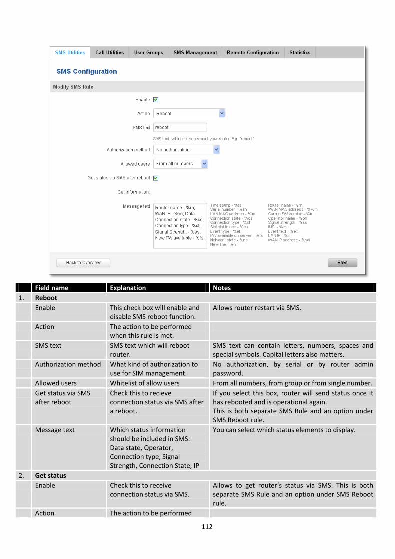
112
Field name Explanation Notes
1. Reboot
Enable This check box will enable and disable SMS reboot function.
Allows router restart via SMS.
Action The action to be performed when this rule is met.
SMS text SMS text which will reboot router.
SMS text can contain letters, numbers, spaces and special symbols. Capital letters also matters.
Authorization method What kind of authorization to use for SIM management.
No authorization, by serial or by router admin password.
Allowed users Whitelist of allow users From all numbers, from group or from single number.
Get status via SMS after reboot
Check this to recieve connection status via SMS after a reboot.
If you select this box, router will send status once it has rebooted and is operational again. This is both separate SMS Rule and an option under SMS Reboot rule.
Message text Which status information should be included in SMS: Data state, Operator, Connection type, Signal Strength, Connection State, IP
You can select which status elements to display.
2. Get status
Enable Check this to receive connection status via SMS.
Allows to get router‘s status via SMS. This is both separate SMS Rule and an option under SMS Reboot rule.
Action The action to be performed
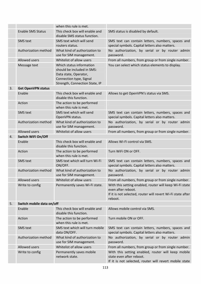
113
when this rule is met.
Enable SMS Status This check box will enable and disable SMS status function.
SMS status is disabled by default.
SMS text SMS text which will send routers status.
SMS text can contain letters, numbers, spaces and special symbols. Capital letters also matters.
Authorization method What kind of authorization to use for SIM management.
No authorization, by serial or by router admin password.
Allowed users Whitelist of allow users From all numbers, from group or from single number.
Message text Which status information should be included in SMS: Data state, Operator, Connection type, Signal Strength, Connection State, IP
You can select which status elements to display.
3. Get OpenVPN status
Enable This check box will enable and disable this function.
Allows to get OpenVPN‘s status via SMS.
Action The action to be performed when this rule is met.
SMS text SMS text which will send OpenVPN status.
SMS text can contain letters, numbers, spaces and special symbols. Capital letters also matters.
Authorization method What kind of authorization to use for SIM management.
No authorization, by serial or by router admin password.
Allowed users Whitelist of allow users From all numbers, from group or from single number.
4. Switch WiFi On/Off
Enable This check box will enable and disable this function.
Allows Wi-Fi control via SMS.
Action The action to be performed when this rule is met.
Turn WiFi ON or OFF.
SMS text SMS text which will turn Wi-Fi ON/OFF.
SMS text can contain letters, numbers, spaces and special symbols. Capital letters also matters.
Authorization method What kind of authorization to use for SIM management.
No authorization, by serial or by router admin password.
Allowed users Whitelist of allow users From all numbers, from group or from single number.
Write to config Permanently saves Wi-Fi state. With this setting enabled, router will keep Wi-Fi state even after reboot. If it is not selected, router will revert Wi-Fi state after reboot.
5. Switch mobile data on/off
Enable This check box will enable and disable this function.
Allows mobile control via SMS.
Action The action to be performed when this rule is met.
Turn mobile ON or OFF.
SMS text SMS text which will turn mobile data ON/OFF.
SMS text can contain letters, numbers, spaces and special symbols. Capital letters also matters.
Authorization method What kind of authorization to use for SIM management.
No authorization, by serial or by router admin password.
Allowed users Whitelist of allow users From all numbers, from group or from single number.
Write to config Permanently saves mobile network state.
With this setting enabled, router will keep mobile state even after reboot. If it is not selected, router will revert mobile state
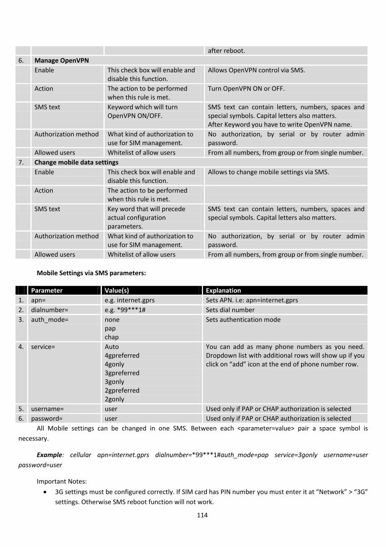
114
after reboot.
6. Manage OpenVPN
Enable This check box will enable and disable this function.
Allows OpenVPN control via SMS.
Action The action to be performed when this rule is met.
Turn OpenVPN ON or OFF.
SMS text Keyword which will turn OpenVPN ON/OFF.
SMS text can contain letters, numbers, spaces and special symbols. Capital letters also matters. After Keyword you have to write OpenVPN name.
Authorization method What kind of authorization to use for SIM management.
No authorization, by serial or by router admin password.
Allowed users Whitelist of allow users From all numbers, from group or from single number.
7. Change mobile data settings
Enable This check box will enable and disable this function.
Allows to change mobile settings via SMS.
Action The action to be performed when this rule is met.
SMS text Key word that will precede actual configuration parameters.
SMS text can contain letters, numbers, spaces and special symbols. Capital letters also matters.
Authorization method What kind of authorization to use for SIM management.
No authorization, by serial or by router admin password.
Allowed users Whitelist of allow users From all numbers, from group or from single number.
Mobile Settings via SMS parameters:
Parameter Value(s) Explanation
1. apn= e.g. internet.gprs Sets APN. i.e: apn=internet.gprs
2. dialnumber= e.g. *99***1# Sets dial number
3. auth_mode= none pap chap
Sets authentication mode
4. service= Auto 4gpreferred 4gonly 3gpreferred 3gonly 2gpreferred 2gonly
You can add as many phone numbers as you need. Dropdown list with additional rows will show up if you click on “add” icon at the end of phone number row.
5. username= user Used only if PAP or CHAP authorization is selected
6. password= user Used only if PAP or CHAP authorization is selected
All Mobile settings can be changed in one SMS. Between each <parameter=value> pair a space symbol is
necessary.
Example: cellular apn=internet.gprs dialnumber=*99***1#auth_mode=pap service=3gonly username=user
password=user
Important Notes:
3G settings must be configured correctly. If SIM card has PIN number you must enter it at “Network” > “3G”
settings. Otherwise SMS reboot function will not work.
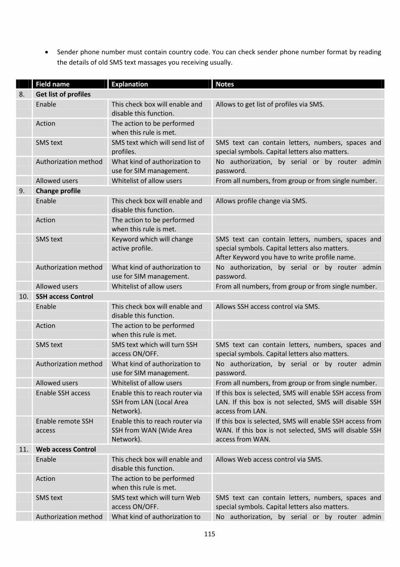
115
Sender phone number must contain country code. You can check sender phone number format by reading
the details of old SMS text massages you receiving usually.
Field name Explanation Notes
8. Get list of profiles
Enable This check box will enable and disable this function.
Allows to get list of profiles via SMS.
Action The action to be performed when this rule is met.
SMS text SMS text which will send list of profiles.
SMS text can contain letters, numbers, spaces and special symbols. Capital letters also matters.
Authorization method What kind of authorization to use for SIM management.
No authorization, by serial or by router admin password.
Allowed users Whitelist of allow users From all numbers, from group or from single number.
9. Change profile
Enable This check box will enable and disable this function.
Allows profile change via SMS.
Action The action to be performed when this rule is met.
SMS text Keyword which will change active profile.
SMS text can contain letters, numbers, spaces and special symbols. Capital letters also matters. After Keyword you have to write profile name.
Authorization method What kind of authorization to use for SIM management.
No authorization, by serial or by router admin password.
Allowed users Whitelist of allow users From all numbers, from group or from single number.
10. SSH access Control
Enable This check box will enable and disable this function.
Allows SSH access control via SMS.
Action The action to be performed when this rule is met.
SMS text SMS text which will turn SSH access ON/OFF.
SMS text can contain letters, numbers, spaces and special symbols. Capital letters also matters.
Authorization method What kind of authorization to use for SIM management.
No authorization, by serial or by router admin password.
Allowed users Whitelist of allow users From all numbers, from group or from single number.
Enable SSH access Enable this to reach router via SSH from LAN (Local Area Network).
If this box is selected, SMS will enable SSH access from LAN. If this box is not selected, SMS will disable SSH access from LAN.
Enable remote SSH access
Enable this to reach router via SSH from WAN (Wide Area Network).
If this box is selected, SMS will enable SSH access from WAN. If this box is not selected, SMS will disable SSH access from WAN.
11. Web access Control
Enable This check box will enable and disable this function.
Allows Web access control via SMS.
Action The action to be performed when this rule is met.
SMS text SMS text which will turn Web access ON/OFF.
SMS text can contain letters, numbers, spaces and special symbols. Capital letters also matters.
Authorization method What kind of authorization to No authorization, by serial or by router admin

116
use for SIM management. password.
Allowed users Whitelist of allow users From all numbers, from group or from single number.
Enable HTTP access Enable this to reach router via HTTP from LAN (Local Area Network).
If this box is selected, SMS will enable HTTP access from LAN. If this box is not selected, SMS will disable HTTP access from LAN.
Enable remote HTTP access
Enable this to reach router via HTTP from WAN (Wide Area Network).
If this box is selected, SMS will enable HTTP access from WAN. If this box is not selected, SMS will disable HTTP access from WAN.
Enable remote HTTPS access
Enable this to reach router via HTTPS from WAN (Wide Area Network).
If this box is selected, SMS will enable HTTPS access from WAN. If this box is not selected, SMS will disable HTTPS access from WAN.
12. Restore to default
Enable This check box will enable and disable this function.
Allows to restore router to default settings via SMS.
Action The action to be performed when this rule is met.
Router will reboot after this rule is executed.
SMS text SMS text which will turn Wi-Fi ON/OFF.
SMS text can contain letters, numbers, spaces and special symbols. Capital letters also matters.
Authorization method What kind of authorization to use for SIM management.
No authorization, by serial or by router admin password.
Allowed users Whitelist of allow users From all numbers, from group or from single number.
13. Force switch SIM
Enable This check box will enable and disable this function.
Allows SIM switch via SMS.
Action The action to be performed when this rule is met.
SMS text SMS text which will change active SIM card to another one.
SMS text can contain letters, numbers, spaces and special symbols. Capital letters also matters.
Authorization method What kind of authorization to use for SIM management.
No authorization, by serial or by router admin password.
Allowed users Whitelist of allow users From all numbers, from group or from single number.
Sender phone number Phone number of person who can receive router status via SMS message.
You can add as many phone numbers as you need. Dropdown list with additional rows will show up if you click on “add” icon at the end of phone number row.
14. Force FW upgrade from server
Enable This check box will enable and disable this function.
Allows to upgrade router‘s FW via SMS.
Action The action to be performed when this rule is met.
Router will reboot after this rule is executed.
SMS text SMS text which will force router to upgrade firmware from server.
SMS text can contain letters, numbers, spaces and special symbols. Capital letters also matters.
Authorization method What kind of authorization to use for SIM management.
No authorization, by serial or by router admin password.
Allowed users Whitelist of allow users From all numbers, from group or from single number.
15. Force Config update from server
Enable This check box will enable and disable this function.
Allows to upgrade router‘s Config via SMS.
Action The action to be performed when this rule is met.
Router will reboot after this rule is executed.
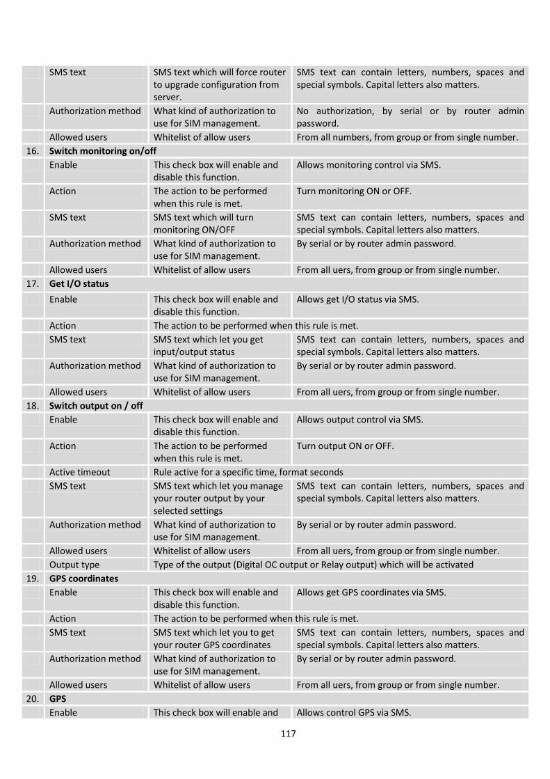
117
SMS text SMS text which will force router to upgrade configuration from server.
SMS text can contain letters, numbers, spaces and special symbols. Capital letters also matters.
Authorization method What kind of authorization to use for SIM management.
No authorization, by serial or by router admin password.
Allowed users Whitelist of allow users From all numbers, from group or from single number.
16. Switch monitoring on/off
Enable This check box will enable and disable this function.
Allows monitoring control via SMS.
Action The action to be performed when this rule is met.
Turn monitoring ON or OFF.
SMS text SMS text which will turn monitoring ON/OFF
SMS text can contain letters, numbers, spaces and special symbols. Capital letters also matters.
Authorization method What kind of authorization to use for SIM management.
By serial or by router admin password.
Allowed users Whitelist of allow users From all uers, from group or from single number.
17. Get I/O status
Enable This check box will enable and disable this function.
Allows get I/O status via SMS.
Action The action to be performed when this rule is met.
SMS text SMS text which let you get input/output status
SMS text can contain letters, numbers, spaces and special symbols. Capital letters also matters.
Authorization method What kind of authorization to use for SIM management.
By serial or by router admin password.
Allowed users Whitelist of allow users From all uers, from group or from single number.
18. Switch output on / off
Enable This check box will enable and disable this function.
Allows output control via SMS.
Action The action to be performed when this rule is met.
Turn output ON or OFF.
Active timeout Rule active for a specific time, format seconds
SMS text SMS text which let you manage your router output by your selected settings
SMS text can contain letters, numbers, spaces and special symbols. Capital letters also matters.
Authorization method What kind of authorization to use for SIM management.
By serial or by router admin password.
Allowed users Whitelist of allow users From all uers, from group or from single number.
Output type Type of the output (Digital OC output or Relay output) which will be activated
19. GPS coordinates
Enable This check box will enable and disable this function.
Allows get GPS coordinates via SMS.
Action The action to be performed when this rule is met.
SMS text SMS text which let you to get your router GPS coordinates
SMS text can contain letters, numbers, spaces and special symbols. Capital letters also matters.
Authorization method What kind of authorization to use for SIM management.
By serial or by router admin password.
Allowed users Whitelist of allow users From all uers, from group or from single number.
20. GPS
Enable This check box will enable and Allows control GPS via SMS.
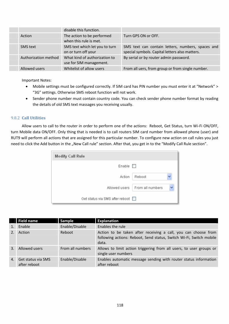
118
disable this function.
Action The action to be performed when this rule is met.
Turn GPS ON or OFF.
SMS text SMS text which let you to turn on or turn off your
SMS text can contain letters, numbers, spaces and special symbols. Capital letters also matters.
Authorization method What kind of authorization to use for SIM management.
By serial or by router admin password.
Allowed users Whitelist of allow users From all uers, from group or from single number.
Important Notes:
Mobile settings must be configured correctly. If SIM card has PIN number you must enter it at “Network” >
“3G” settings. Otherwise SMS reboot function will not work.
Sender phone number must contain country code. You can check sender phone number format by reading
the details of old SMS text massages you receiving usually.
9.8.2 Call Utilities
Allow users to call to the router in order to perform one of the actions: Reboot, Get Status, turn Wi-Fi ON/OFF,
turn Mobile data ON/OFF. Only thing that is needed is to call routers SIM card number from allowed phone (user) and
RUT9 will perform all actions that are assigned for this particular number. To configure new action on call rules you just
need to click the Add button in the „New Call rule” section. After that, you get in to the “Modify Call Rule section”.
Field name Sample Explanation
1. Enable Enable/Disable Enables the rule
2. Action Reboot Action to be taken after receiving a call, you can choose from following actions: Reboot, Send status, Switch Wi-Fi, Switch mobile data.
3. Allowed users From all numbers Allows to limit action triggering from all users, to user groups or single user numbers
4. Get status via SMS after reboot
Enable/Disable Enables automatic message sending with router status information after reboot
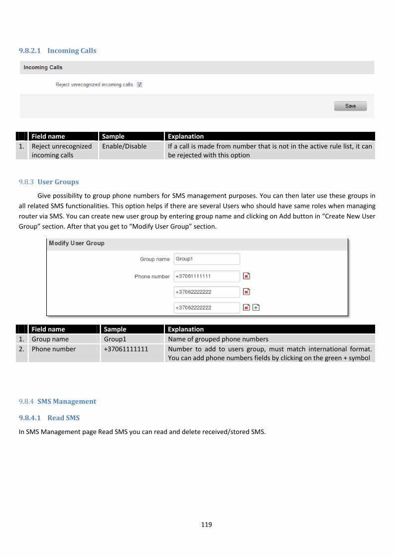
119
9.8.2.1 Incoming Calls
Field name Sample Explanation
1. Reject unrecognized incoming calls
Enable/Disable If a call is made from number that is not in the active rule list, it can be rejected with this option
9.8.3 User Groups
Give possibility to group phone numbers for SMS management purposes. You can then later use these groups in
all related SMS functionalities. This option helps if there are several Users who should have same roles when managing
router via SMS. You can create new user group by entering group name and clicking on Add button in “Create New User
Group” section. After that you get to “Modify User Group” section.
Field name Sample Explanation
1. Group name Group1 Name of grouped phone numbers
2. Phone number +37061111111 Number to add to users group, must match international format. You can add phone numbers fields by clicking on the green + symbol
9.8.4 SMS Management
9.8.4.1 Read SMS
In SMS Management page Read SMS you can read and delete received/stored SMS.
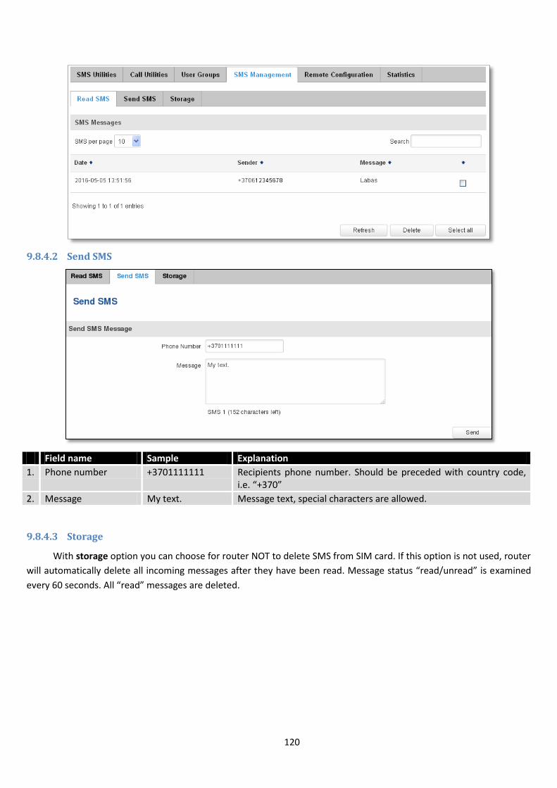
120
9.8.4.2 Send SMS
Field name Sample Explanation
1. Phone number +3701111111 Recipients phone number. Should be preceded with country code, i.e. “+370”
2. Message My text. Message text, special characters are allowed.
9.8.4.3 Storage
With storage option you can choose for router NOT to delete SMS from SIM card. If this option is not used, router
will automatically delete all incoming messages after they have been read. Message status “read/unread” is examined
every 60 seconds. All “read” messages are deleted.
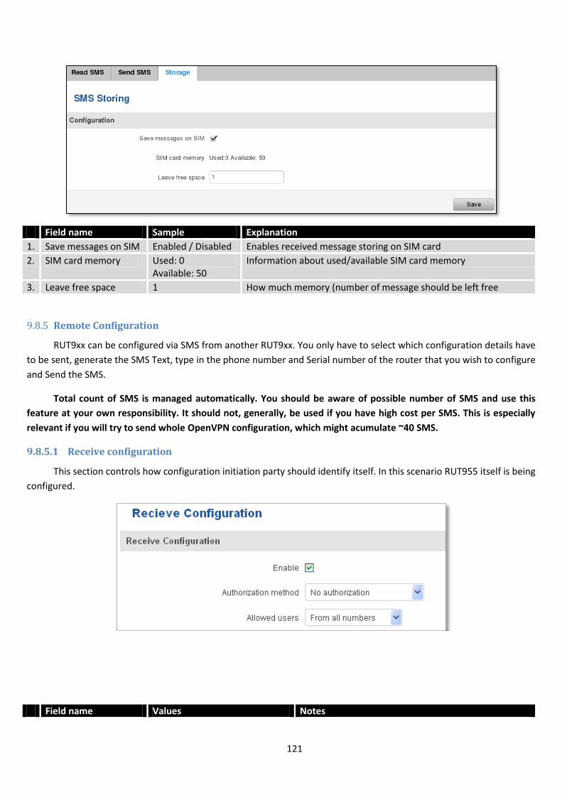
121
Field name Sample Explanation
1. Save messages on SIM Enabled / Disabled Enables received message storing on SIM card
2. SIM card memory Used: 0 Available: 50
Information about used/available SIM card memory
3. Leave free space 1 How much memory (number of message should be left free
9.8.5 Remote Configuration
RUT9xx can be configured via SMS from another RUT9xx. You only have to select which configuration details have
to be sent, generate the SMS Text, type in the phone number and Serial number of the router that you wish to configure
and Send the SMS.
Total count of SMS is managed automatically. You should be aware of possible number of SMS and use this
feature at your own responsibility. It should not, generally, be used if you have high cost per SMS. This is especially
relevant if you will try to send whole OpenVPN configuration, which might acumulate ~40 SMS.
9.8.5.1 Receive configuration
This section controls how configuration initiation party should identify itself. In this scenario RUT955 itself is being
configured.
Field name Values Notes
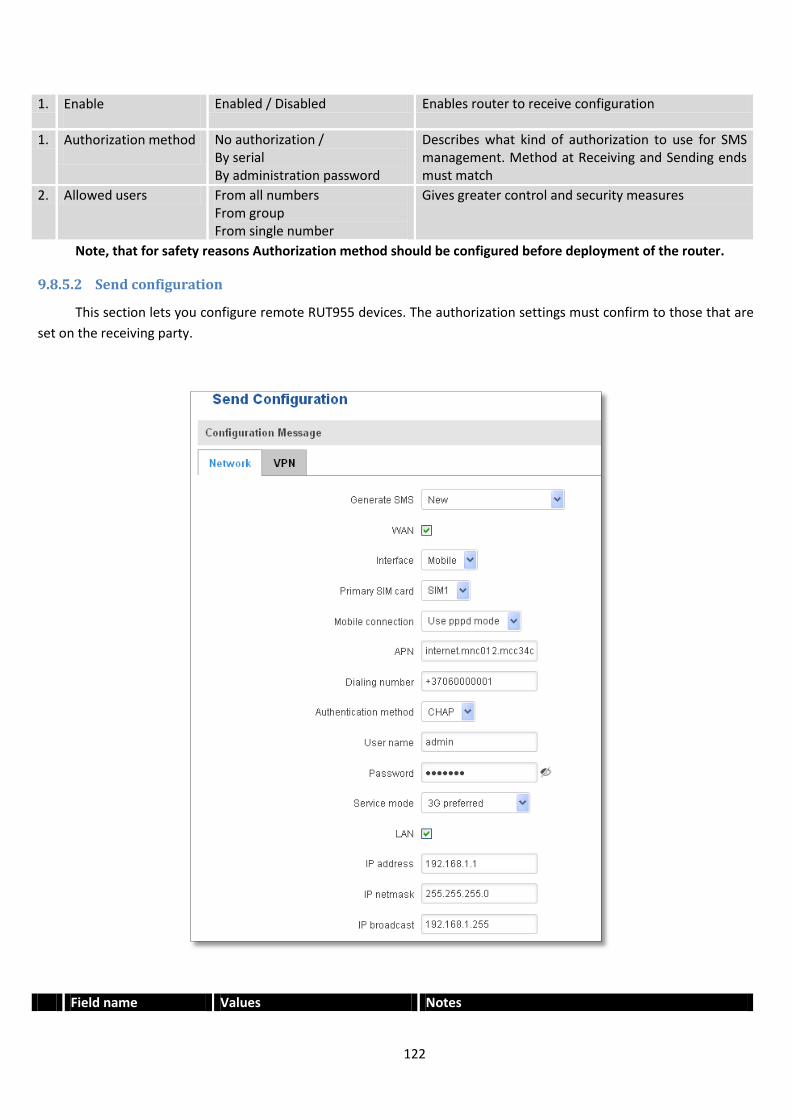
122
1. Enable Enabled / Disabled Enables router to receive configuration
1. Authorization method No authorization / By serial By administration password
Describes what kind of authorization to use for SMS management. Method at Receiving and Sending ends must match
2. Allowed users From all numbers From group From single number
Gives greater control and security measures
Note, that for safety reasons Authorization method should be configured before deployment of the router.
9.8.5.2 Send configuration
This section lets you configure remote RUT955 devices. The authorization settings must confirm to those that are
set on the receiving party.
Field name Values Notes
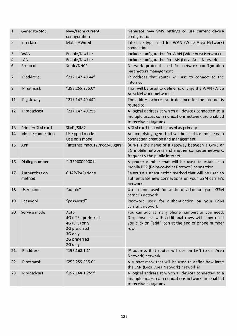
123
1. Generate SMS New/From current configuration
Generate new SMS settings or use current device configuration
2. Interface Mobile/Wired Interface type used for WAN (Wide Area Network) connection
3. WAN Enable/Disable Include configuration for WAN (Wide Area Network)
4. LAN Enable/Disable Include configuration for LAN (Local Area Network)
6. Protocol Static/DHCP Network protocol used for network configuration parameters management
7. IP address “217.147.40.44” IP address that router will use to connect to the internet
8. IP netmask “255.255.255.0” That will be used to define how large the WAN (Wide Area Network) network is
11. IP gateway “217.147.40.44” The address where traffic destined for the internet is routed to
12. IP broadcast “217.147.40.255” A logical address at which all devices connected to a multiple-access communications network are enabled to receive datagrams.
13. Primary SIM card SIM1/SIM2 A SIM card that will be used as primary
14. Mobile connection Use pppd mode Use ndis mode
An underlying agent that will be used for mobile data connection creation and management
15. APN “internet.mnc012.mcc345.gprs” (APN) is the name of a gateway between a GPRS or 3G mobile networks and another computer network, frequently the public Internet.
16. Dialing number “+37060000001” A phone number that will be used to establish a mobile PPP (Point-to-Point Protocol) connection
17. Authentication method
CHAP/PAP/None Select an authentication method that will be used to authenticate new connections on your GSM carrier's network
18. User name “admin” User name used for authentication on your GSM carrier's network
19. Password “password” Password used for authentication on your GSM carrier's network
20. Service mode Auto 4G (LTE ) preferred 4G (LTE) only 3G preferred 3G only 2G preferred 2G only
You can add as many phone numbers as you need. Dropdown list with additional rows will show up if you click on “add” icon at the end of phone number row.
21. IP address “192.168.1.1” IP address that router will use on LAN (Local Area Network) network
22. IP netmask “255.255.255.0” A subnet mask that will be used to define how large the LAN (Local Area Network) network is
23. IP broadcast “192.168.1.255” A logical address at which all devices connected to a multiple-access communications network are enabled to receive datagrams
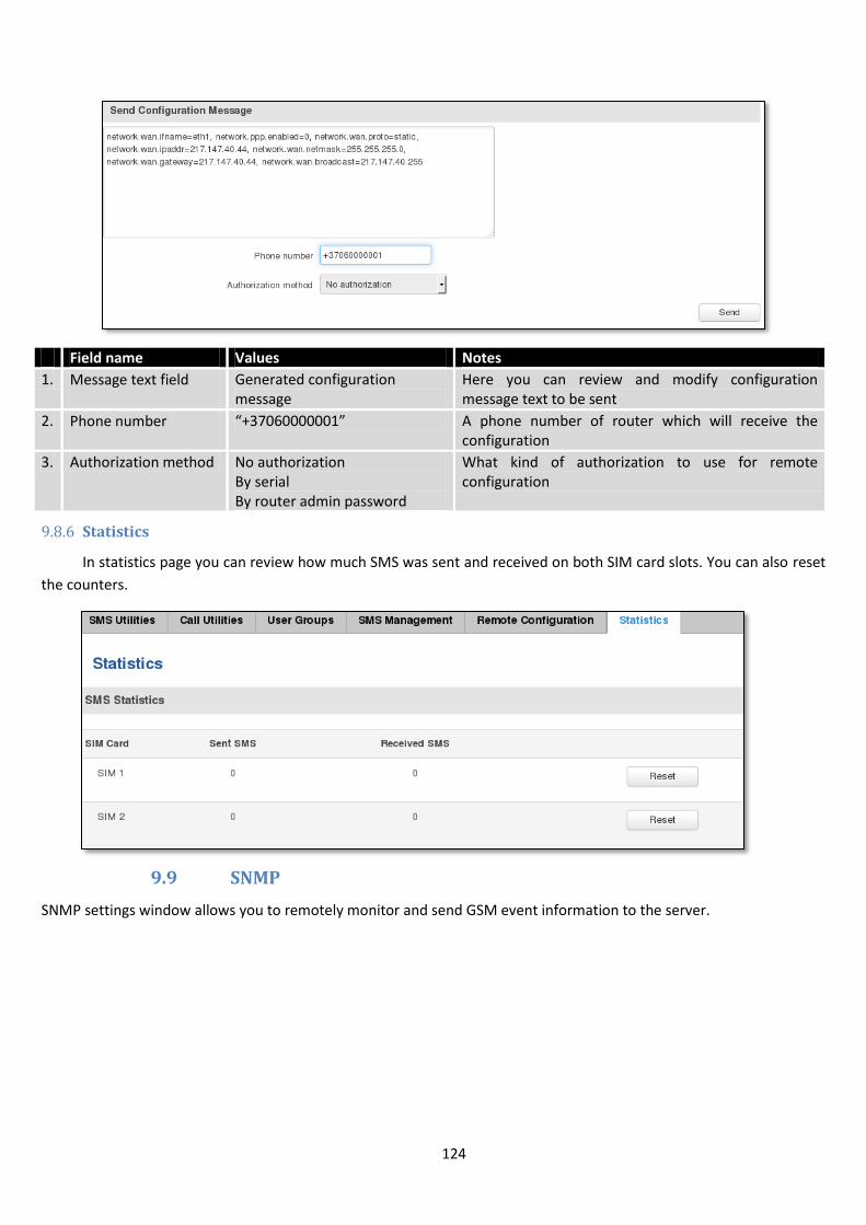
124
Field name Values Notes
1. Message text field Generated configuration message
Here you can review and modify configuration message text to be sent
2. Phone number “+37060000001” A phone number of router which will receive the configuration
3. Authorization method No authorization By serial By router admin password
What kind of authorization to use for remote configuration
9.8.6 Statistics
In statistics page you can review how much SMS was sent and received on both SIM card slots. You can also reset
the counters.
9.9 SNMP
SNMP settings window allows you to remotely monitor and send GSM event information to the server.
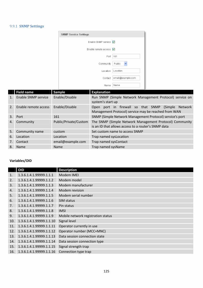
125
9.9.1 SNMP Settings
Field name Sample Explanation
1. Enable SNMP service Enable/Disable Run SNMP (Simple Network Management Protocol) service on system's start up
2. Enable remote access Enable/Disable Open port in firewall so that SNMP (Simple Network Management Protocol) service may be reached from WAN
3. Port 161 SNMP (Simple Network Management Protocol) service's port
4. Community Public/Private/Custom The SNMP (Simple Network Management Protocol) Community is an ID that allows access to a router's SNMP data
5. Community name custom Set custom name to access SNMP
6. Location Location Trap named sysLocation
7. Contact [email protected] Trap named sysContact
8. Name Name Trap named sysName
Variables/OID
OID Description
1. 1.3.6.1.4.1.99999.1.1.1 Modem IMEI
2. 1.3.6.1.4.1.99999.1.1.2 Modem model
3. 1.3.6.1.4.1.99999.1.1.3 Modem manufacturer
4. 1.3.6.1.4.1.99999.1.1.4 Modem revision
5. 1.3.6.1.4.1.99999.1.1.5 Modem serial number
6. 1.3.6.1.4.1.99999.1.1.6 SIM status
7. 1.3.6.1.4.1.99999.1.1.7 Pin status
8. 1.3.6.1.4.1.99999.1.1.8 IMSI
9. 1.3.6.1.4.1.99999.1.1.9 Mobile network registration status
10. 1.3.6.1.4.1.99999.1.1.10 Signal level
11. 1.3.6.1.4.1.99999.1.1.11 Operator currently in use
12. 1.3.6.1.4.1.99999.1.1.12 Operator number (MCC+MNC)
13. 1.3.6.1.4.1.99999.1.1.13 Data session connection state
14. 1.3.6.1.4.1.99999.1.1.14 Data session connection type
15. 1.3.6.1.4.1.99999.1.1.15 Signal strength trap
16. 1.3.6.1.4.1.99999.1.1.16 Connection type trap
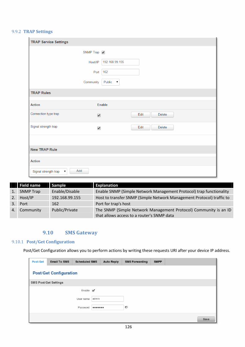
126
9.9.2 TRAP Settings
Field name Sample Explanation
1. SNMP Trap Enable/Disable Enable SNMP (Simple Network Management Protocol) trap functionality
2. Host/IP 192.168.99.155 Host to transfer SNMP (Simple Network Management Protocol) traffic to
3. Port 162 Port for trap's host
4. Community Public/Private The SNMP (Simple Network Management Protocol) Community is an ID that allows access to a router's SNMP data
9.10 SMS Gateway
9.10.1 Post/Get Configuration
Post/Get Configuration allows you to perform actions by writing these requests URI after your device IP address.
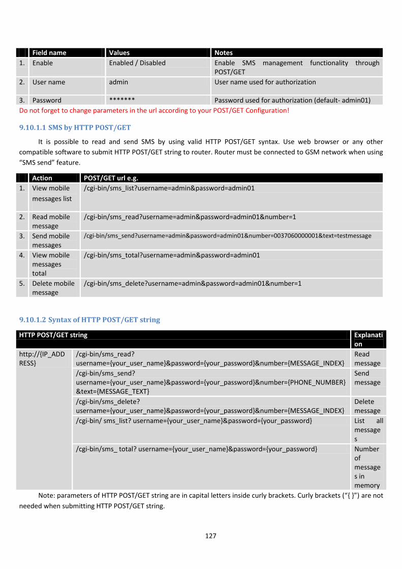
127
Field name Values Notes
1. Enable Enabled / Disabled Enable SMS management functionality through POST/GET
2. User name admin User name used for authorization
3. Password ******* Password used for authorization (default- admin01)
Do not forget to change parameters in the url according to your POST/GET Configuration!
9.10.1.1 SMS by HTTP POST/GET
It is possible to read and send SMS by using valid HTTP POST/GET syntax. Use web browser or any other
compatible software to submit HTTP POST/GET string to router. Router must be connected to GSM network when using
“SMS send” feature.
Action POST/GET url e.g.
1. View mobile
messages list
/cgi-bin/sms_list?username=admin&password=admin01
2. Read mobile message
/cgi-bin/sms_read?username=admin&password=admin01&number=1
3. Send mobile messages
/cgi-bin/sms_send?username=admin&password=admin01&number=0037060000001&text=testmessage
4. View mobile messages total
/cgi-bin/sms_total?username=admin&password=admin01
5. Delete mobile message
/cgi-bin/sms_delete?username=admin&password=admin01&number=1
9.10.1.2 Syntax of HTTP POST/GET string
HTTP POST/GET string Explanation
http://IP_ADDRESS
/cgi-bin/sms_read? username=your_user_name&password=your_password&number=MESSAGE_INDEX
Read message
/cgi-bin/sms_send? username=your_user_name&password=your_password&number=PHONE_NUMBER&text=MESSAGE_TEXT
Send message
/cgi-bin/sms_delete? username=your_user_name&password=your_password&number=MESSAGE_INDEX
Delete message
/cgi-bin/ sms_list? username=your_user_name&password=your_password List all messages
/cgi-bin/sms_ total? username=your_user_name&password=your_password Number of messages in memory
Note: parameters of HTTP POST/GET string are in capital letters inside curly brackets. Curly brackets (“ ”) are not
needed when submitting HTTP POST/GET string.
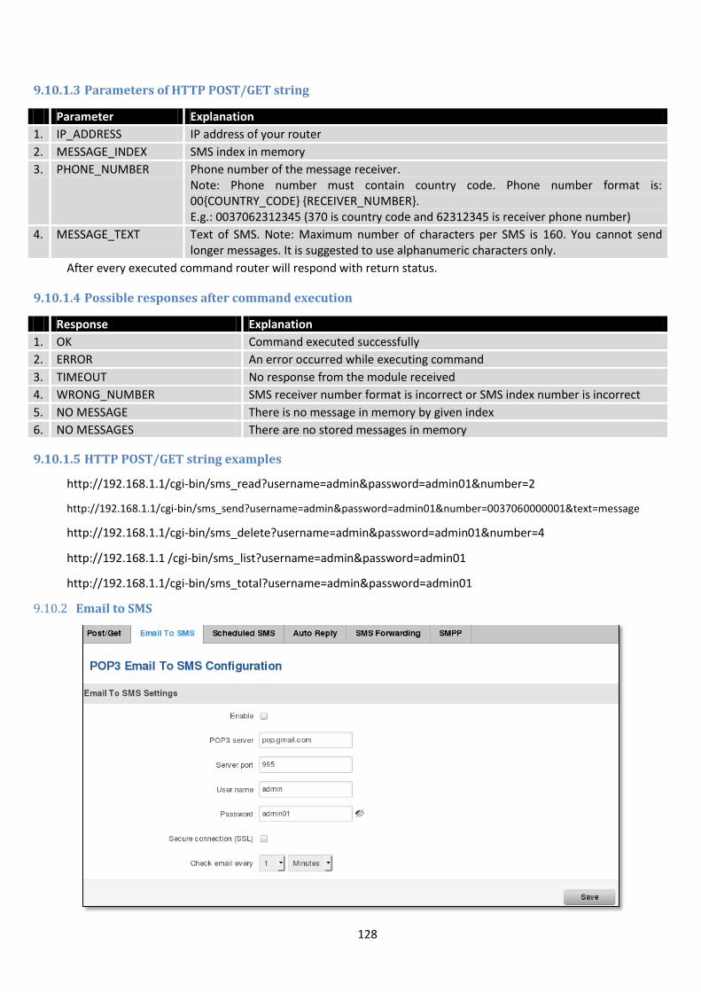
128
9.10.1.3 Parameters of HTTP POST/GET string
Parameter Explanation
1. IP_ADDRESS IP address of your router
2. MESSAGE_INDEX SMS index in memory
3. PHONE_NUMBER Phone number of the message receiver. Note: Phone number must contain country code. Phone number format is: 00COUNTRY_CODE RECEIVER_NUMBER. E.g.: 0037062312345 (370 is country code and 62312345 is receiver phone number)
4. MESSAGE_TEXT Text of SMS. Note: Maximum number of characters per SMS is 160. You cannot send longer messages. It is suggested to use alphanumeric characters only.
After every executed command router will respond with return status.
9.10.1.4 Possible responses after command execution
Response Explanation
1. OK Command executed successfully
2. ERROR An error occurred while executing command
3. TIMEOUT No response from the module received
4. WRONG_NUMBER SMS receiver number format is incorrect or SMS index number is incorrect
5. NO MESSAGE There is no message in memory by given index
6. NO MESSAGES There are no stored messages in memory
9.10.1.5 HTTP POST/GET string examples
http://192.168.1.1/cgi-bin/sms_read?username=admin&password=admin01&number=2
http://192.168.1.1/cgi-bin/sms_send?username=admin&password=admin01&number=0037060000001&text=message
http://192.168.1.1/cgi-bin/sms_delete?username=admin&password=admin01&number=4
http://192.168.1.1 /cgi-bin/sms_list?username=admin&password=admin01
http://192.168.1.1/cgi-bin/sms_total?username=admin&password=admin01
9.10.2 Email to SMS
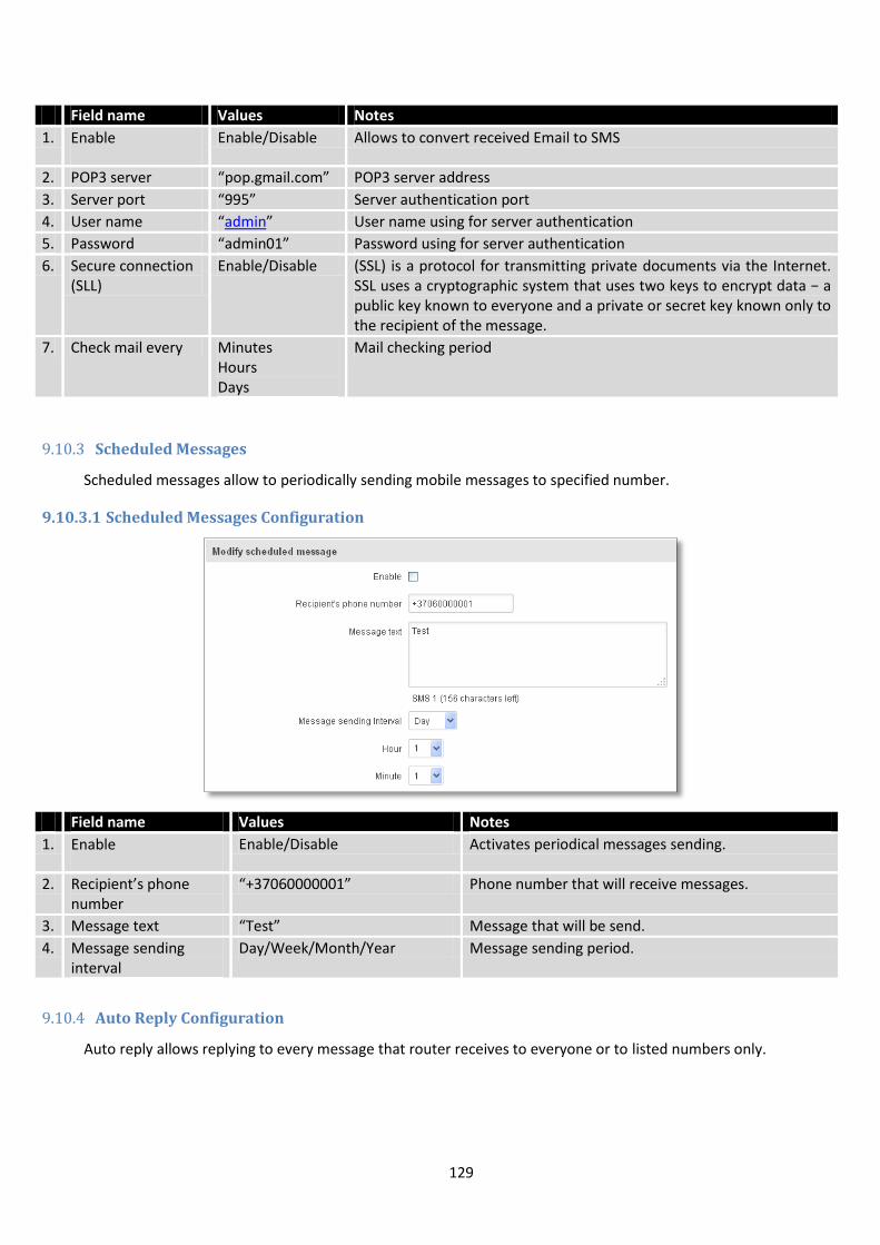
129
Field name Values Notes
1. Enable Enable/Disable Allows to convert received Email to SMS
2. POP3 server “pop.gmail.com” POP3 server address
3. Server port “995” Server authentication port
4. User name “admin” User name using for server authentication
5. Password “admin01” Password using for server authentication
6. Secure connection (SLL)
Enable/Disable (SSL) is a protocol for transmitting private documents via the Internet. SSL uses a cryptographic system that uses two keys to encrypt data − a public key known to everyone and a private or secret key known only to the recipient of the message.
7. Check mail every Minutes Hours Days
Mail checking period
9.10.3 Scheduled Messages
Scheduled messages allow to periodically sending mobile messages to specified number.
9.10.3.1 Scheduled Messages Configuration
Field name Values Notes
1. Enable Enable/Disable Activates periodical messages sending.
2. Recipient’s phone number
“+37060000001” Phone number that will receive messages.
3. Message text “Test” Message that will be send.
4. Message sending interval
Day/Week/Month/Year Message sending period.
9.10.4 Auto Reply Configuration
Auto reply allows replying to every message that router receives to everyone or to listed numbers only.
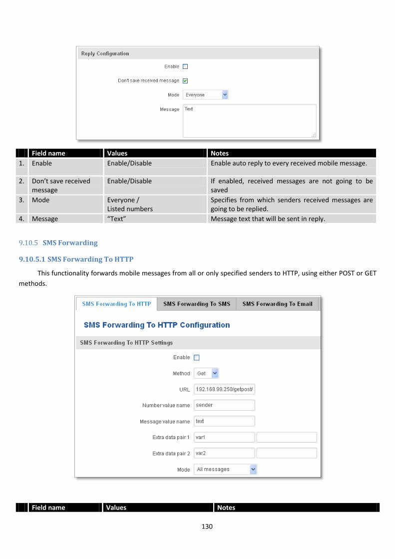
130
Field name Values Notes
1. Enable Enable/Disable Enable auto reply to every received mobile message.
2. Don’t save received message
Enable/Disable If enabled, received messages are not going to be saved
3. Mode Everyone / Listed numbers
Specifies from which senders received messages are going to be replied.
4. Message “Text” Message text that will be sent in reply.
9.10.5 SMS Forwarding
9.10.5.1 SMS Forwarding To HTTP
This functionality forwards mobile messages from all or only specified senders to HTTP, using either POST or GET
methods.
Field name Values Notes
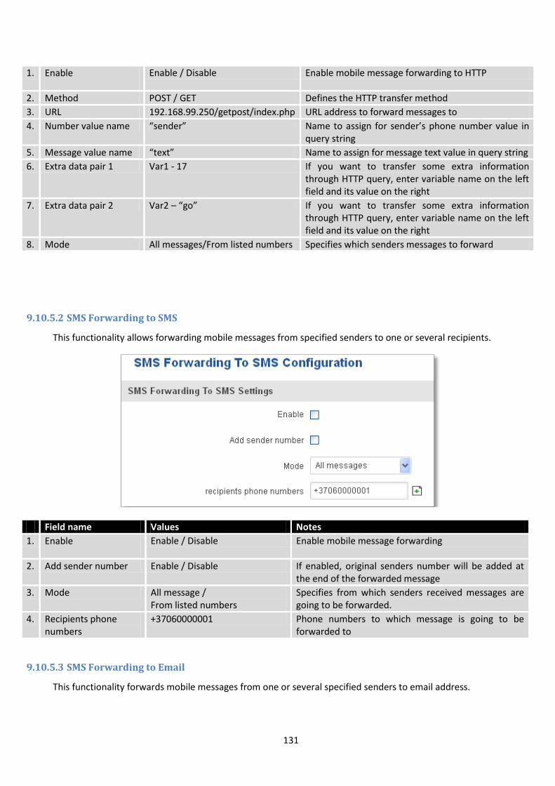
131
1. Enable Enable / Disable Enable mobile message forwarding to HTTP
2. Method POST / GET Defines the HTTP transfer method
3. URL 192.168.99.250/getpost/index.php URL address to forward messages to
4. Number value name “sender” Name to assign for sender’s phone number value in query string
5. Message value name “text” Name to assign for message text value in query string
6. Extra data pair 1 Var1 - 17 If you want to transfer some extra information through HTTP query, enter variable name on the left field and its value on the right
7. Extra data pair 2 Var2 – “go” If you want to transfer some extra information through HTTP query, enter variable name on the left field and its value on the right
8. Mode All messages/From listed numbers Specifies which senders messages to forward
9.10.5.2 SMS Forwarding to SMS
This functionality allows forwarding mobile messages from specified senders to one or several recipients.
Field name Values Notes
1. Enable Enable / Disable Enable mobile message forwarding
2. Add sender number Enable / Disable If enabled, original senders number will be added at the end of the forwarded message
3. Mode All message / From listed numbers
Specifies from which senders received messages are going to be forwarded.
4. Recipients phone numbers
+37060000001 Phone numbers to which message is going to be forwarded to
9.10.5.3 SMS Forwarding to Email
This functionality forwards mobile messages from one or several specified senders to email address.
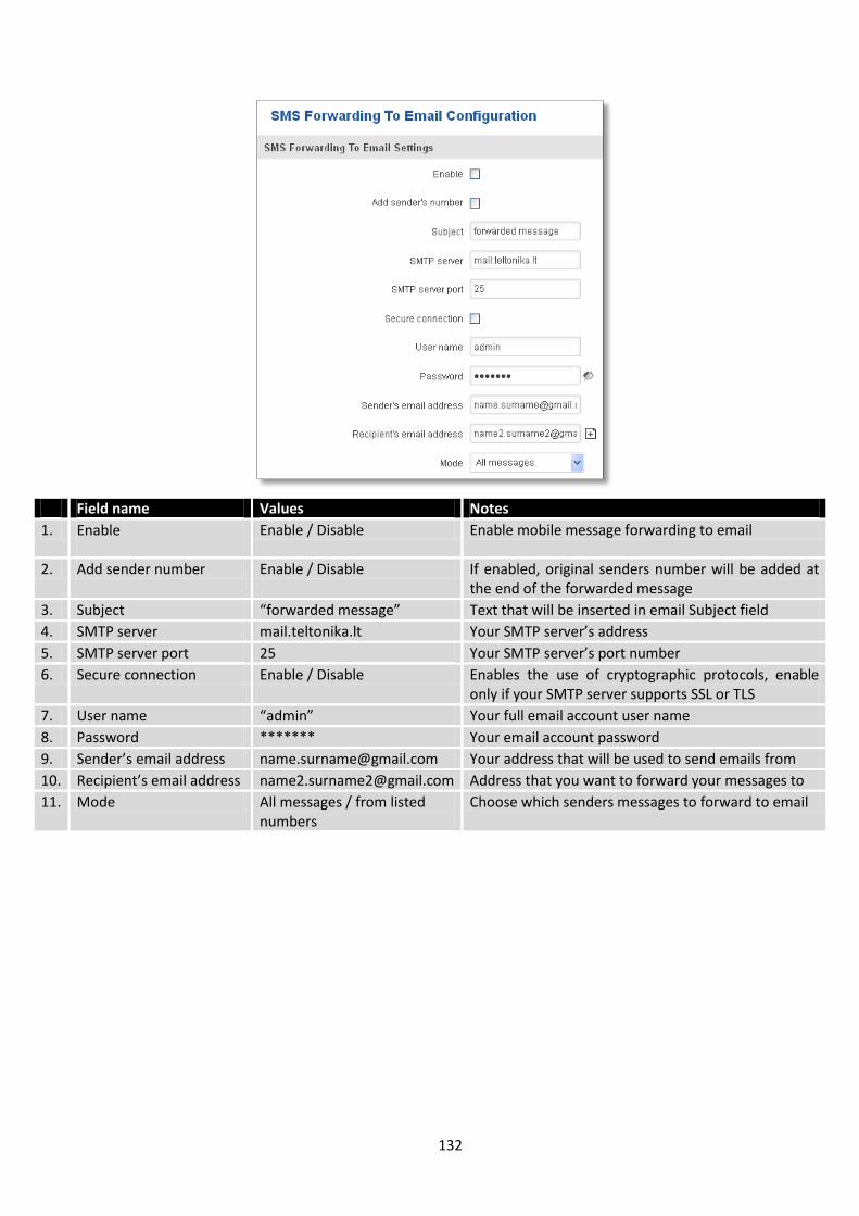
132
Field name Values Notes
1. Enable Enable / Disable Enable mobile message forwarding to email
2. Add sender number Enable / Disable If enabled, original senders number will be added at the end of the forwarded message
3. Subject “forwarded message” Text that will be inserted in email Subject field
4. SMTP server mail.teltonika.lt Your SMTP server’s address
5. SMTP server port 25 Your SMTP server’s port number
6. Secure connection Enable / Disable Enables the use of cryptographic protocols, enable only if your SMTP server supports SSL or TLS
7. User name “admin” Your full email account user name
8. Password ******* Your email account password
9. Sender’s email address [email protected] Your address that will be used to send emails from
10. Recipient’s email address [email protected] Address that you want to forward your messages to
11. Mode All messages / from listed numbers
Choose which senders messages to forward to email
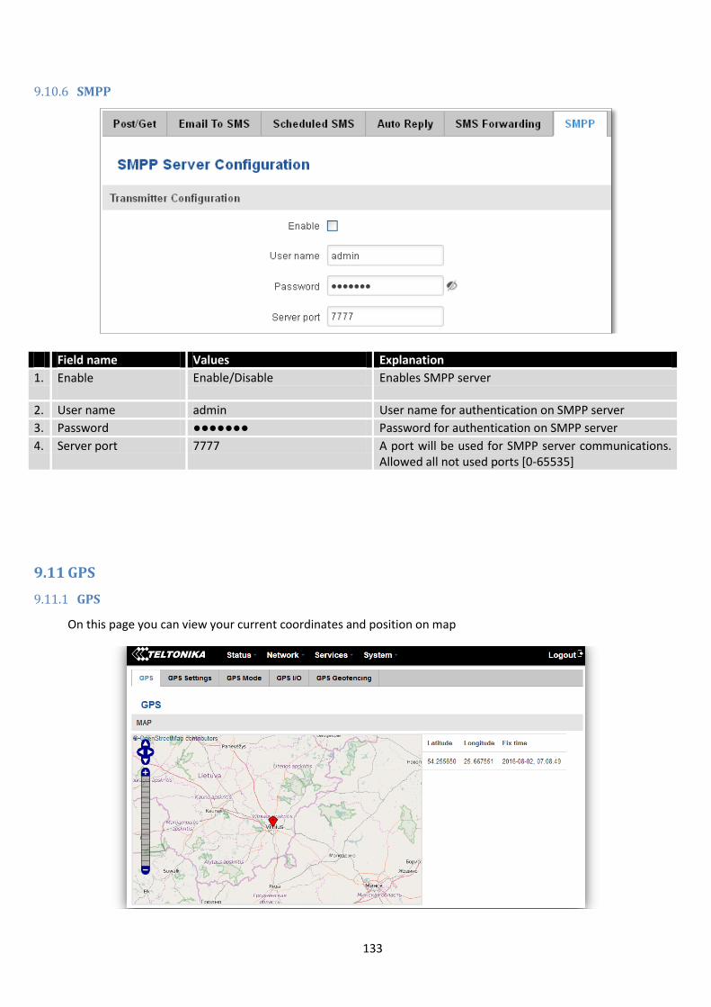
133
9.10.6 SMPP
Field name Values Explanation
1. Enable Enable/Disable Enables SMPP server
2. User name admin User name for authentication on SMPP server
3. Password Password for authentication on SMPP server
4. Server port 7777 A port will be used for SMPP server communications. Allowed all not used ports [0-65535]
9.11 GPS
9.11.1 GPS
On this page you can view your current coordinates and position on map

134
9.11.2 GPS Settings
This is the GPS parameters comfiguration page.
9.11.3 GPS Mode
Data sending
Field name Values Notes
1. Enable GPS service Enable / Disable By enabling it will start generate your location coordinates
2. Enable GPS Data to server Enable / Disable By enabling it will start generate your location coordinates and transfer them to specified server
3. Remote host / IP address 212.47.99.61 Server IP address or domain name to send coordinates to
4. Port 17050 Server port used for data transfer
5. Protocol TCP or UDP Protocol to be used for coordinates data transfer to server

135
Rules This table shows created GPS rules for data sending.
GPS Configuration GPS configuration section allows to save several different configurations for GPS data collection, active
configuration is automaticaly selected when configured conditions are met.
9.11.4 GPS I/O
Check Analog
Input Rules In this table shows created Input rules.
Field name Values Notes
1. Min period 5 Period (in seconds) for data collection
2. Min distance 200 Distance difference (in meters) between last registered and current coordinates to collect data (even if Min period have not passed yet)
3. Min angle 30 Minimal angle difference between last registered and current coordinates to collect data (even if Min period have not passed yet)
4. Min saved records 20 Minimal amount of coordinates registered, to send them to server immediately (even if Send period have not passed yet)
5. Send period 50 Period for sending collected data to server
Field name Values Notes
1. WAN Mobile/ Wired/ WiFi Interface which needs to be used to activate this configuration
2. Type Home/ Roaming/ Both Mobile connection state needed to activate this configuration
3. Digital Isolated Input Low logic level/ High logic level/ Both Input state needed to activate this configuration
Field name Values Notes
1. Interval (sec) 5 Interval to check analog input value
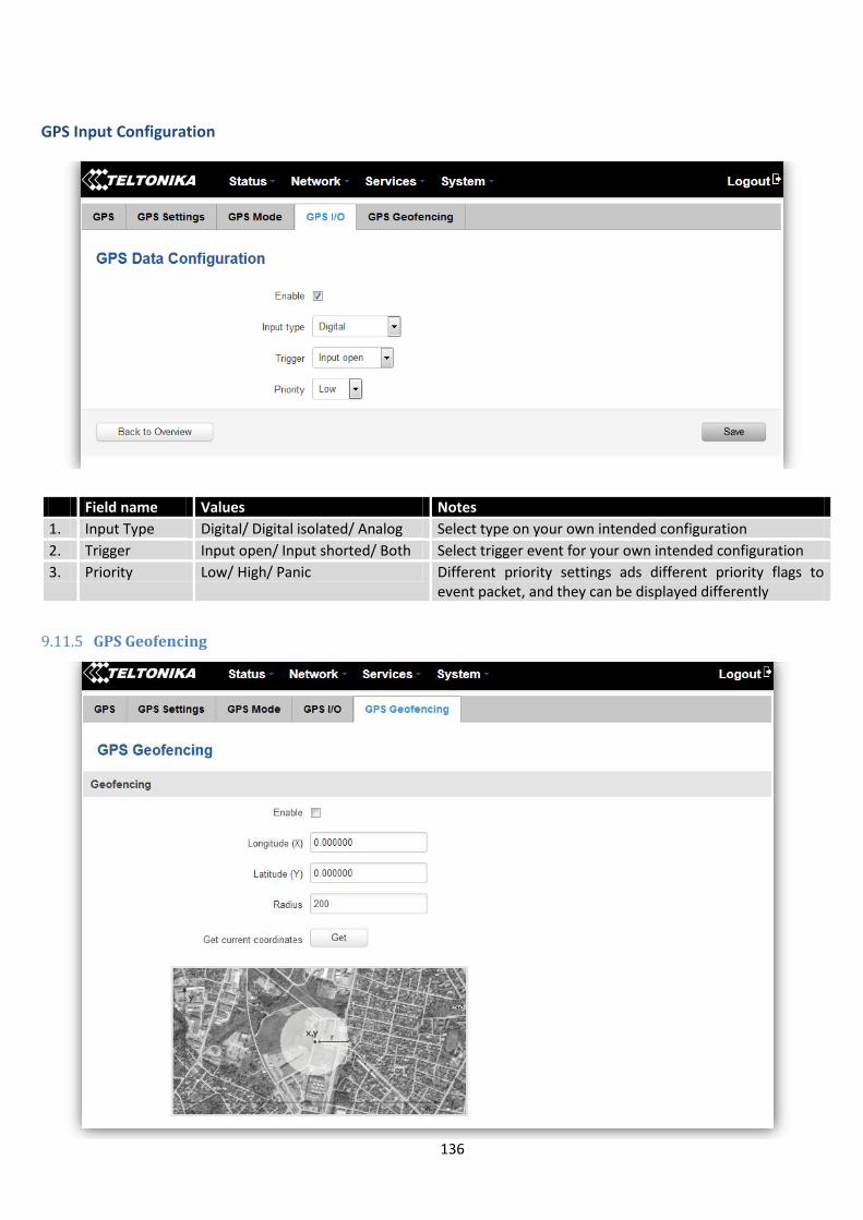
136
GPS Input Configuration
9.11.5 GPS Geofencing
Field name Values Notes
1. Input Type Digital/ Digital isolated/ Analog Select type on your own intended configuration
2. Trigger Input open/ Input shorted/ Both Select trigger event for your own intended configuration
3. Priority Low/ High/ Panic Different priority settings ads different priority flags to event packet, and they can be displayed differently
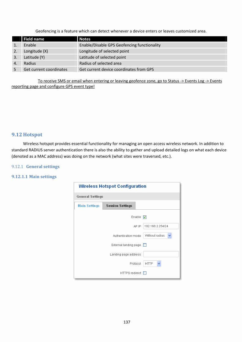
137
Geofencing is a feature which can detect whenever a device enters or leaves customized area.
To receive SMS or email when entering or leaving geofence zone, go to Status -> Events Log -> Events
reporting page and configure GPS event type!
9.12 Hotspot
Wireless hotspot provides essential functionality for managing an open access wireless network. In addition to
standard RADIUS server authentication there is also the ability to gather and upload detailed logs on what each device
(denoted as a MAC address) was doing on the network (what sites were traversed, etc.).
9.12.1 General settings
9.12.1.1 Main settings
Field name Notes
1. Enable Enable/Disable GPS Geofencing functionality
2. Longitude (X) Longitude of selected point
3. Latitude (Y) Latitude of selected point
4. Radius Radius of selected area
5 Get current coordinates Get current device coordinates from GPS
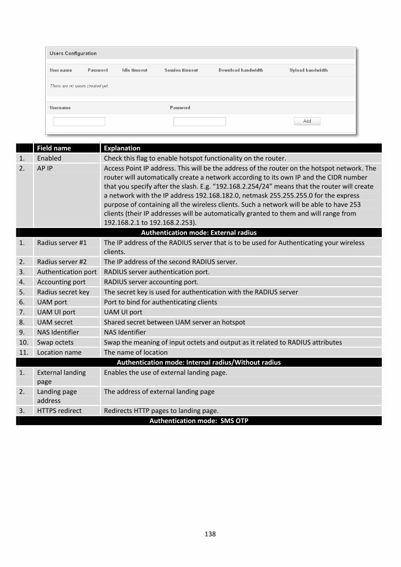
138
Field name Explanation
1. Enabled Check this flag to enable hotspot functionality on the router.
2. AP IP Access Point IP address. This will be the address of the router on the hotspot network. The router will automatically create a network according to its own IP and the CIDR number that you specify after the slash. E.g. “192.168.2.254/24” means that the router will create a network with the IP address 192.168.182.0, netmask 255.255.255.0 for the express purpose of containing all the wireless clients. Such a network will be able to have 253 clients (their IP addresses will be automatically granted to them and will range from 192.168.2.1 to 192.168.2.253).
Authentication mode: External radius
1. Radius server #1 The IP address of the RADIUS server that is to be used for Authenticating your wireless clients.
2. Radius server #2 The IP address of the second RADIUS server.
3. Authentication port RADIUS server authentication port.
4. Accounting port RADIUS server accounting port.
5. Radius secret key The secret key is used for authentication with the RADIUS server
6. UAM port Port to bind for authenticating clients
7. UAM UI port UAM UI port
8. UAM secret Shared secret between UAM server an hotspot
9. NAS Identifier NAS Identifier
10. Swap octets Swap the meaning of input octets and output as it related to RADIUS attributes
11. Location name The name of location
Authentication mode: Internal radius/Without radius
1. External landing page
Enables the use of external landing page.
2. Landing page address
The address of external landing page
3. HTTPS redirect Redirects HTTP pages to landing page.
Authentication mode: SMS OTP
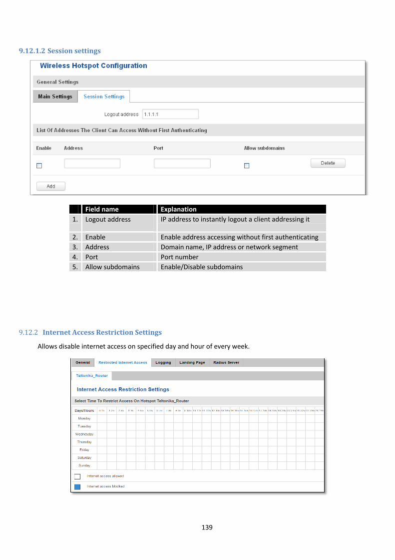
139
9.12.1.2 Session settings
Field name Explanation
1. Logout address IP address to instantly logout a client addressing it
2. Enable Enable address accessing without first authenticating
3. Address Domain name, IP address or network segment
4. Port Port number
5. Allow subdomains Enable/Disable subdomains
9.12.2 Internet Access Restriction Settings
Allows disable internet access on specified day and hour of every week.
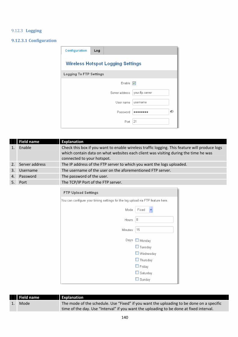
140
9.12.3 Logging
9.12.3.1 Configuration
Field name Explanation
1. Enable Check this box if you want to enable wireless traffic logging. This feature will produce logs which contain data on what websites each client was visiting during the time he was connected to your hotspot.
2. Server address The IP address of the FTP server to which you want the logs uploaded.
3. Username The username of the user on the aforementioned FTP server.
4. Password The password of the user.
5. Port The TCP/IP Port of the FTP server.
Field name Explanation
1. Mode The mode of the schedule. Use “Fixed” if you want the uploading to be done on a specific time of the day. Use “Interval” if you want the uploading to be done at fixed interval.
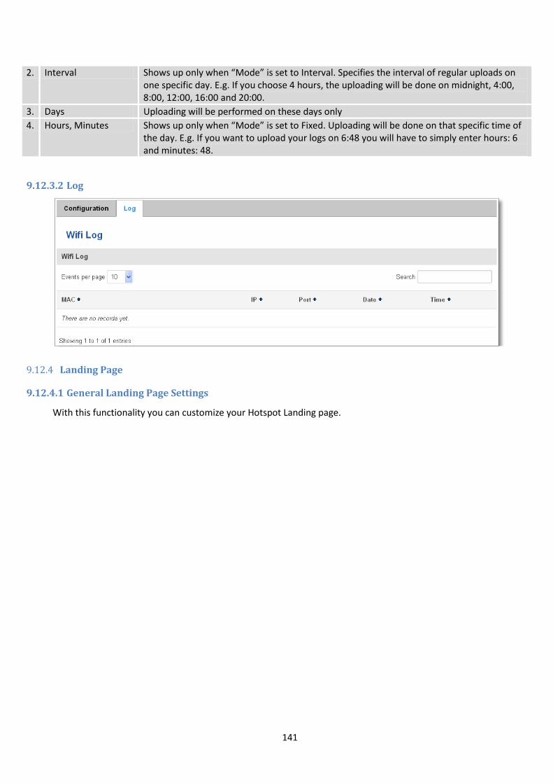
141
2. Interval Shows up only when “Mode” is set to Interval. Specifies the interval of regular uploads on one specific day. E.g. If you choose 4 hours, the uploading will be done on midnight, 4:00, 8:00, 12:00, 16:00 and 20:00.
3. Days Uploading will be performed on these days only
4. Hours, Minutes Shows up only when “Mode” is set to Fixed. Uploading will be done on that specific time of the day. E.g. If you want to upload your logs on 6:48 you will have to simply enter hours: 6 and minutes: 48.
9.12.3.2 Log
9.12.4 Landing Page
9.12.4.1 General Landing Page Settings
With this functionality you can customize your Hotspot Landing page.
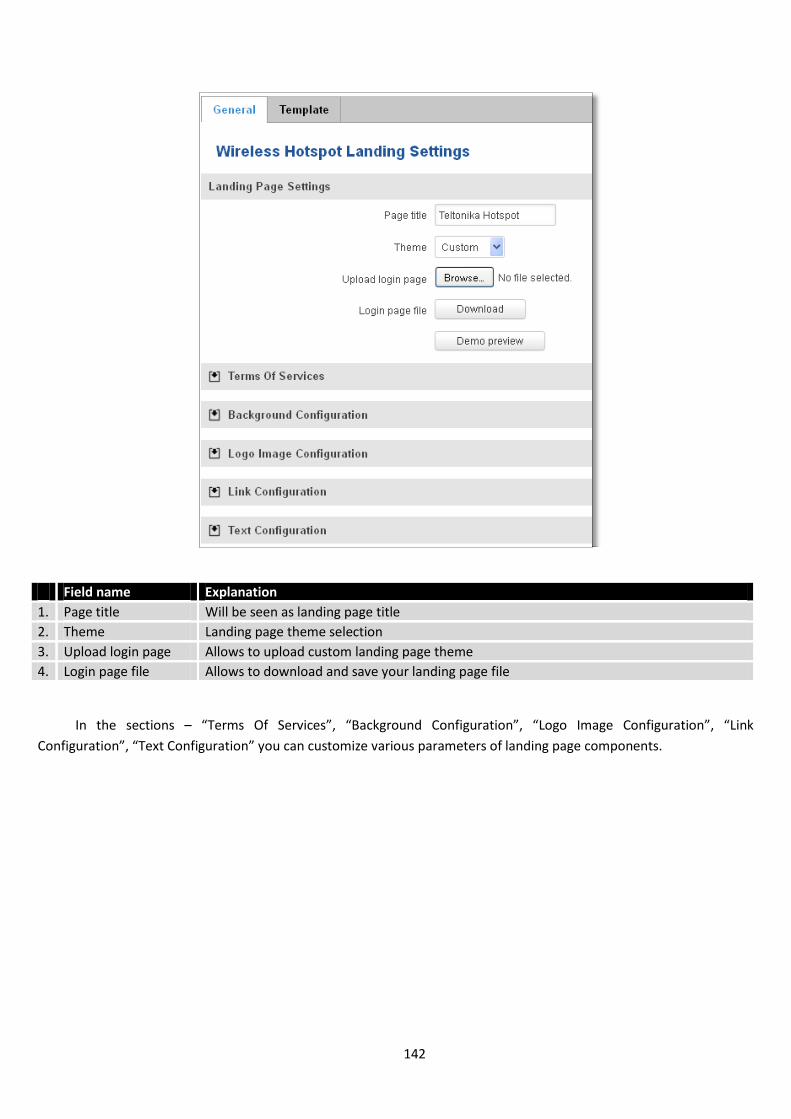
142
Field name Explanation
1. Page title Will be seen as landing page title
2. Theme Landing page theme selection
3. Upload login page Allows to upload custom landing page theme
4. Login page file Allows to download and save your landing page file
In the sections – “Terms Of Services”, “Background Configuration”, “Logo Image Configuration”, “Link
Configuration”, “Text Configuration” you can customize various parameters of landing page components.
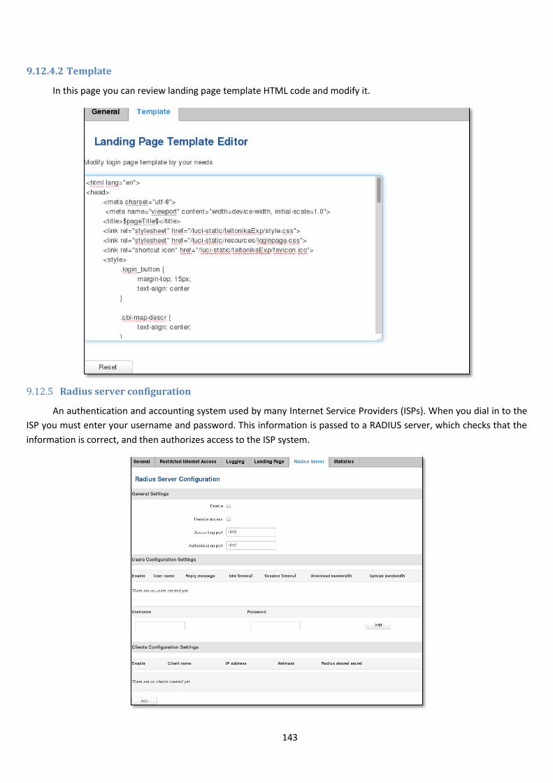
143
9.12.4.2 Template
In this page you can review landing page template HTML code and modify it.
9.12.5 Radius server configuration
An authentication and accounting system used by many Internet Service Providers (ISPs). When you dial in to the
ISP you must enter your username and password. This information is passed to a RADIUS server, which checks that the
information is correct, and then authorizes access to the ISP system.
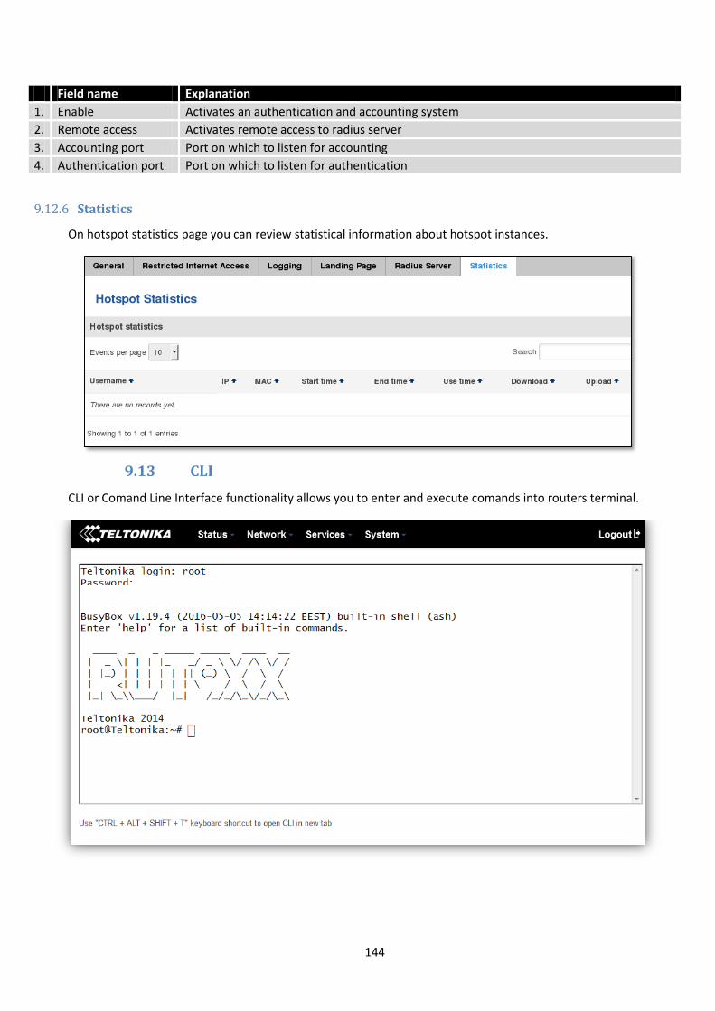
144
Field name Explanation
1. Enable Activates an authentication and accounting system
2. Remote access Activates remote access to radius server
3. Accounting port Port on which to listen for accounting
4. Authentication port Port on which to listen for authentication
9.12.6 Statistics
On hotspot statistics page you can review statistical information about hotspot instances.
9.13 CLI
CLI or Comand Line Interface functionality allows you to enter and execute comands into routers terminal.
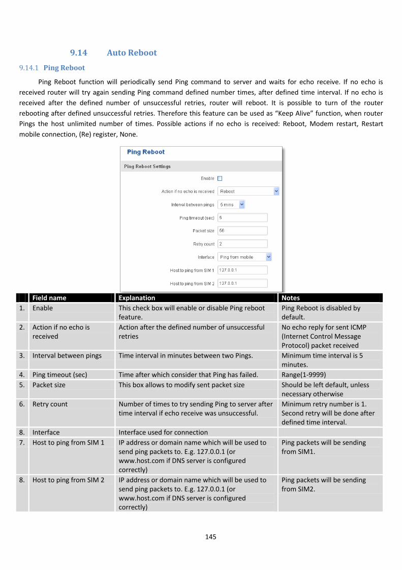
145
9.14 Auto Reboot
9.14.1 Ping Reboot
Ping Reboot function will periodically send Ping command to server and waits for echo receive. If no echo is
received router will try again sending Ping command defined number times, after defined time interval. If no echo is
received after the defined number of unsuccessful retries, router will reboot. It is possible to turn of the router
rebooting after defined unsuccessful retries. Therefore this feature can be used as “Keep Alive” function, when router
Pings the host unlimited number of times. Possible actions if no echo is received: Reboot, Modem restart, Restart
mobile connection, (Re) register, None.
Field name Explanation Notes
1. Enable This check box will enable or disable Ping reboot feature.
Ping Reboot is disabled by default.
2. Action if no echo is received
Action after the defined number of unsuccessful retries
No echo reply for sent ICMP (Internet Control Message Protocol) packet received
3. Interval between pings Time interval in minutes between two Pings. Minimum time interval is 5 minutes.
4. Ping timeout (sec) Time after which consider that Ping has failed. Range(1-9999)
5. Packet size This box allows to modify sent packet size Should be left default, unless necessary otherwise
6. Retry count Number of times to try sending Ping to server after time interval if echo receive was unsuccessful.
Minimum retry number is 1. Second retry will be done after defined time interval.
8. Interface Interface used for connection
7. Host to ping from SIM 1 IP address or domain name which will be used to send ping packets to. E.g. 127.0.0.1 (or www.host.com if DNS server is configured correctly)
Ping packets will be sending from SIM1.
8. Host to ping from SIM 2 IP address or domain name which will be used to send ping packets to. E.g. 127.0.0.1 (or www.host.com if DNS server is configured correctly)
Ping packets will be sending from SIM2.
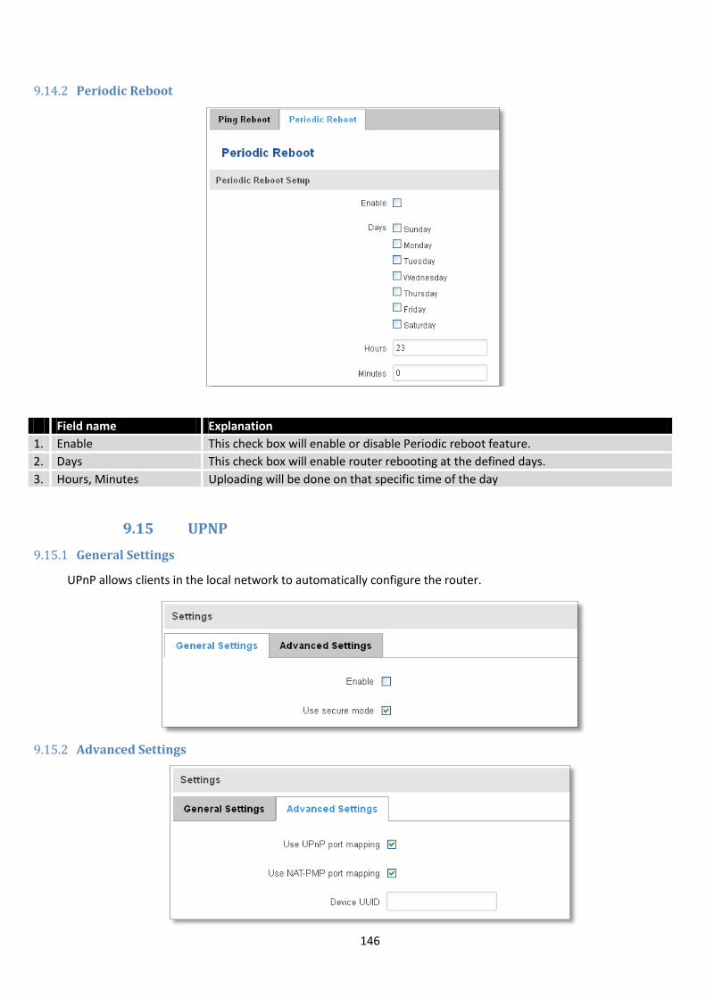
146
9.14.2 Periodic Reboot
Field name Explanation
1. Enable This check box will enable or disable Periodic reboot feature.
2. Days This check box will enable router rebooting at the defined days.
3. Hours, Minutes Uploading will be done on that specific time of the day
9.15 UPNP
9.15.1 General Settings
UPnP allows clients in the local network to automatically configure the router.
9.15.2 Advanced Settings
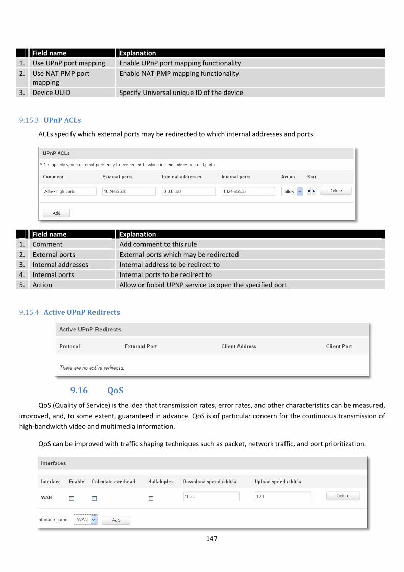
147
Field name Explanation
1. Use UPnP port mapping Enable UPnP port mapping functionality
2. Use NAT-PMP port mapping
Enable NAT-PMP mapping functionality
3. Device UUID Specify Universal unique ID of the device
9.15.3 UPnP ACLs
ACLs specify which external ports may be redirected to which internal addresses and ports.
Field name Explanation
1. Comment Add comment to this rule
2. External ports External ports which may be redirected
3. Internal addresses Internal address to be redirect to
4. Internal ports Internal ports to be redirect to
5. Action Allow or forbid UPNP service to open the specified port
9.15.4 Active UPnP Redirects
9.16 QoS
QoS (Quality of Service) is the idea that transmission rates, error rates, and other characteristics can be measured,
improved, and, to some extent, guaranteed in advance. QoS is of particular concern for the continuous transmission of
high-bandwidth video and multimedia information.
QoS can be improved with traffic shaping techniques such as packet, network traffic, and port prioritization.
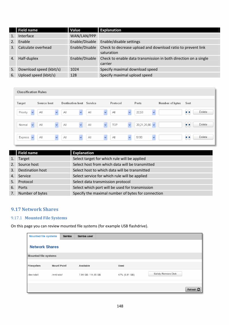
148
Field name Value Explanation
1. Interface WAN/LAN/PPP
2. Enable Enable/Disable Enable/disable settings
3. Calculate overhead Enable/Disable Check to decrease upload and download ratio to prevent link saturation
4. Half-duplex Enable/Disable Check to enable data transmission in both direction on a single carrier
5. Download speed (kbit/s) 1024 Specify maximal download speed
6. Upload speed (kbit/s) 128 Specify maximal upload speed
Field name Explanation
1. Target Select target for which rule will be applied
2. Source host Select host from which data will be transmitted
3. Destination host Select host to which data will be transmitted
4. Service Select service for which rule will be applied
5. Protocol Select data transmission protocol
6. Ports Select which port will be used for transmission
7. Number of bytes Specify the maximal number of bytes for connection
9.17 Network Shares
9.17.1 Mounted File Systems
On this page you can review mounted file systems (for example USB flashdrive).
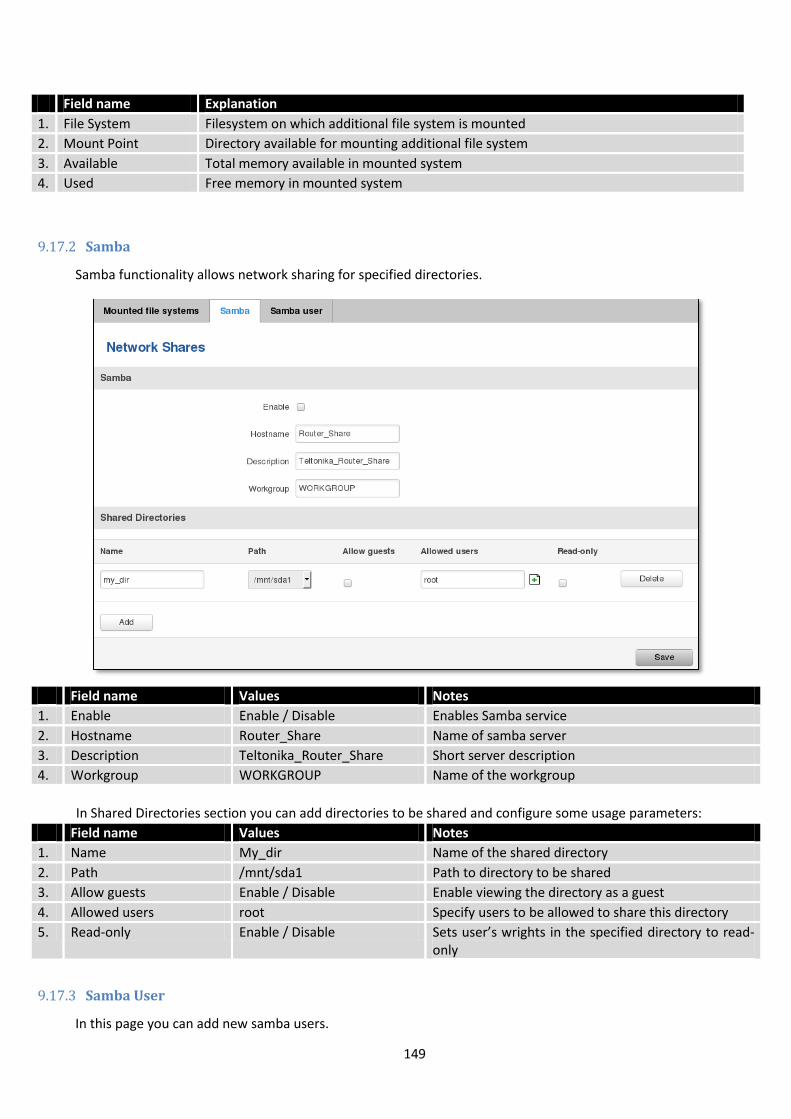
149
Field name Explanation
1. File System Filesystem on which additional file system is mounted
2. Mount Point Directory available for mounting additional file system
3. Available Total memory available in mounted system
4. Used Free memory in mounted system
9.17.2 Samba
Samba functionality allows network sharing for specified directories.
Field name Values Notes
1. Enable Enable / Disable Enables Samba service
2. Hostname Router_Share Name of samba server
3. Description Teltonika_Router_Share Short server description
4. Workgroup WORKGROUP Name of the workgroup
In Shared Directories section you can add directories to be shared and configure some usage parameters:
Field name Values Notes
1. Name My_dir Name of the shared directory
2. Path /mnt/sda1 Path to directory to be shared
3. Allow guests Enable / Disable Enable viewing the directory as a guest
4. Allowed users root Specify users to be allowed to share this directory
5. Read-only Enable / Disable Sets user’s wrights in the specified directory to read-only
9.17.3 Samba User
In this page you can add new samba users.
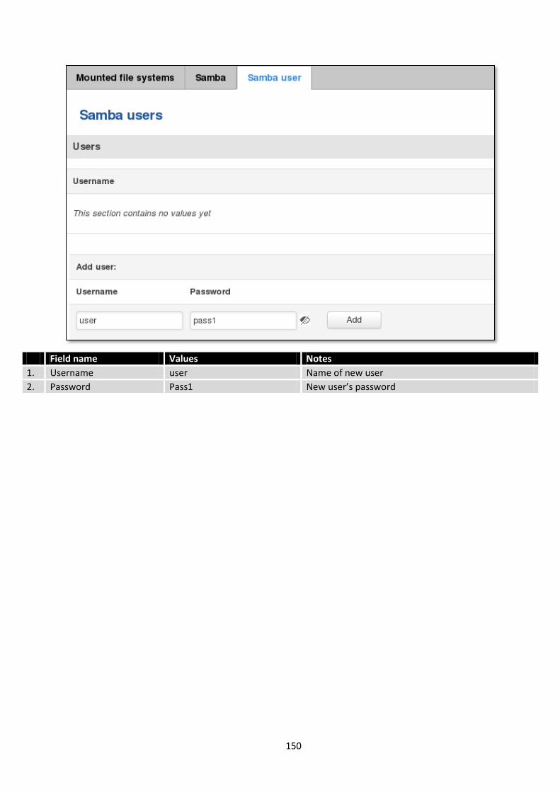
150
Field name Values Notes
1. Username user Name of new user
2. Password Pass1 New user’s password

151
9.18 Input/Output
9.18.1 Status
In this page you can review the current state of all router’s inputs and outputs.
9.18.2 Input
Allows you to set up input parameters and specify what actions should be taken after triggering event of any input. In check analog section you can change the analog input checking interval.
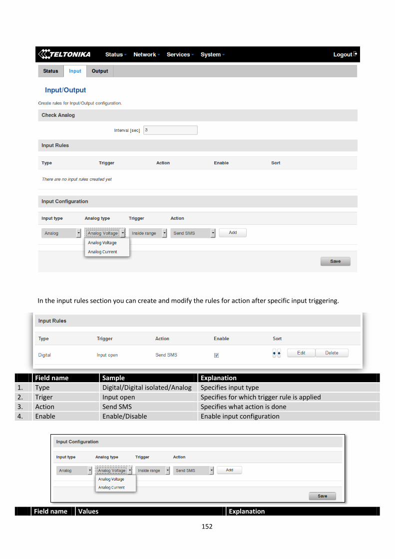
152
In the input rules section you can create and modify the rules for action after specific input triggering.
Field name Sample Explanation
1. Type Digital/Digital isolated/Analog Specifies input type
2. Triger Input open Specifies for which trigger rule is applied
3. Action Send SMS Specifies what action is done
4. Enable Enable/Disable Enable input configuration
Field name Values Explanation
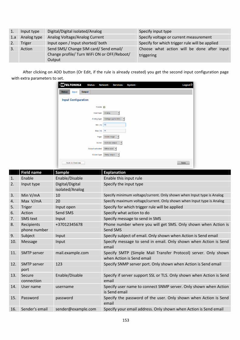
153
1. Input type Digital/Digital isolated/Analog Specify input type
1.a Analog type Analog Voltage/Analog Current Specify voltage or current measurement
2. Triger Input open / Input shorted/ both Specify for which trigger rule will be applied
3. Action Send SMS/ Change SIM card/ Send email/ Change profile/ Turn WiFi ON or OFF/Reboot/ Output
Choose what action will be done after input
triggering
After clicking on ADD button (Or Edit, if the rule is already created) you get the second input configuration page
with extra parameters to set.
Field name Sample Explanation
1. Enable Enable/Disable Enable this input rule
2. Input type Digital/Digital isolated/Analog
Specify the input type
3. Min V/mA 10 Specify minimum voltage/current. Only shown when Input type is Analog
4. Max V/mA 20 Specify maximum voltage/current. Only shown when Input type is Analog
5. Triger Input open Specify for which trigger rule will be applied
6. Action Send SMS Specify what action to do
7. SMS text Input Specify message to send in SMS
8. Recipients phone number
+37012345678 Phone number where you will get SMS. Only shown when Action is Send SMS
9. Subject Input Specify subject of email. Only shown when Action is Send email
10. Message Input Specify message to send in email. Only shown when Action is Send email
11. SMTP server mail.example.com Specify SMTP (Simple Mail Transfer Protocol) server. Only shown when Action is Send email
12. SMTP server port
123 Specify SNMP server port. Only shown when Action is Send email
13. Secure connection
Enable/Disable Specify if server support SSL or TLS. Only shown when Action is Send email
14. User name username Specify user name to connect SNMP server. Only shown when Action is Send email
15. Password password Specify the password of the user. Only shown when Action is Send email
16. Sender's email [email protected] Specify your email address. Only shown when Action is Send email
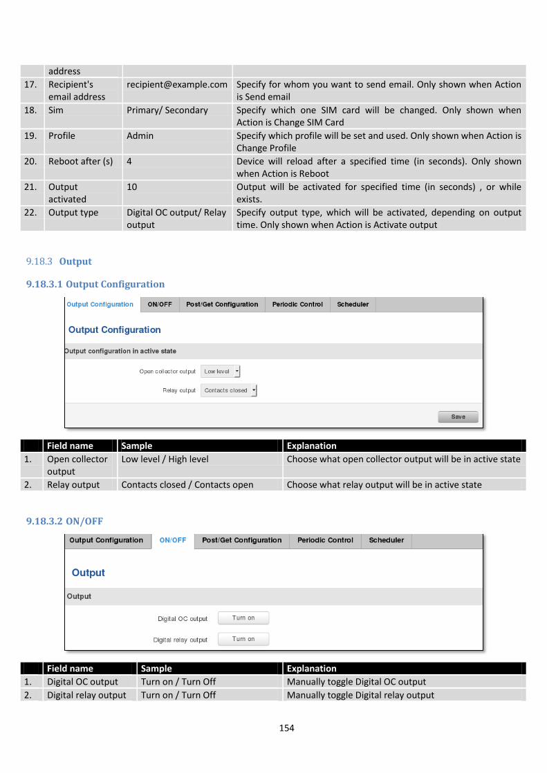
154
address
17. Recipient's email address
[email protected] Specify for whom you want to send email. Only shown when Action is Send email
18. Sim Primary/ Secondary Specify which one SIM card will be changed. Only shown when Action is Change SIM Card
19. Profile Admin Specify which profile will be set and used. Only shown when Action is Change Profile
20. Reboot after (s) 4 Device will reload after a specified time (in seconds). Only shown when Action is Reboot
21. Output activated
10 Output will be activated for specified time (in seconds) , or while exists.
22. Output type Digital OC output/ Relay output
Specify output type, which will be activated, depending on output time. Only shown when Action is Activate output
9.18.3 Output
9.18.3.1 Output Configuration
Field name Sample Explanation
1. Open collector output
Low level / High level Choose what open collector output will be in active state
2. Relay output Contacts closed / Contacts open Choose what relay output will be in active state
9.18.3.2 ON/OFF
Field name Sample Explanation
1. Digital OC output Turn on / Turn Off Manually toggle Digital OC output
2. Digital relay output Turn on / Turn Off Manually toggle Digital relay output
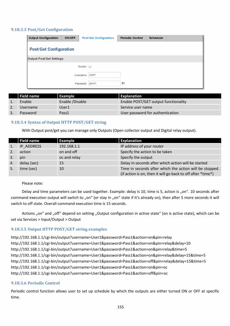
155
9.18.3.3 Post/Get Configuration
Field name Example Explanation
1. Enable Enable /Disable Enable POST/GET output functionality
2. Username User1 Service user name
3. Password Pass1 User password for authentication
9.18.3.4 Syntax of Output HTTP POST/GET string
With Output post/get you can manage only Outputs (Open collector output and Digital relay output).
Field name Example Explanation
1. IP_ADDRESS 192.168.1.1 IP address of your router
2. action on and off Specify the action to be taken
3. pin oc and relay Specify the output
4. delay (sec) 15 Delay in seconds after which action will be started
5. time (sec) 10 Time in seconds after which the action will be stopped. (if action is on, then it will go back to off after *time*)
Please note:
Delay and time parameters can be used together. Example: delay is 10, time is 5, action is „on“. 10 seconds after
command execution output will switch to „on“ (or stay in „on“ state if it‘s already on), then after 5 more seconds it will
switch to off state. Overall command execution time is 15 seconds.
Actions „on“ and „off“ depend on setting „Output configuration in active state“ (on is active state), which can be
set via Services > Input/Output > Output
9.18.3.5 Output HTTP POST/GET string examples
http://192.168.1.1/cgi-bin/output?username=User1&password=Pass1&action=on&pin=relay
http://192.168.1.1/cgi-bin/output?username=User1&password=Pass1&action=on&pin=relay&delay=10
http://192.168.1.1/cgi-bin/output?username=User1&password=Pass1&action=on&pin=relay&time=5
http://192.168.1.1/cgi-bin/output?username=User1&password=Pass1&action=on&pin=relay&delay=15&time=5
http://192.168.1.1/cgi-bin/output?username=User1&password=Pass1&action=off&pin=relay&delay=15&time=5
http://192.168.1.1/cgi-bin/output?username=User1&password=Pass1&action=on&pin=oc
http://192.168.1.1/cgi-bin/output?username=User1&password=Pass1&action=off&pin=oc
9.18.3.6 Periodic Control
Periodic control function allows user to set up schedule by which the outputs are either turned ON or OFF at specific
time.
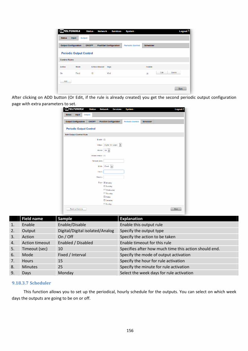
156
After clicking on ADD button (Or Edit, if the rule is already created) you get the second periodic output configuration
page with extra parameters to set.
Field name Sample Explanation
1. Enable Enable/Disable Enable this output rule
2. Output Digital/Digital isolated/Analog Specify the output type
3. Action On / Off Specify the action to be taken
4. Action timeout Enabled / Disabled Enable timeout for this rule
5. Timeout (sec) 10 Specifies after how much time this action should end.
6. Mode Fixed / Interval Specify the mode of output activation
7. Hours 15 Specify the hour for rule activation
8. Minutes 25 Specify the minute for rule activation
9. Days Monday Select the week days for rule activation
9.18.3.7 Scheduler
This function allows you to set up the periodical, hourly schedule for the outputs. You can select on which week
days the outputs are going to be on or off.
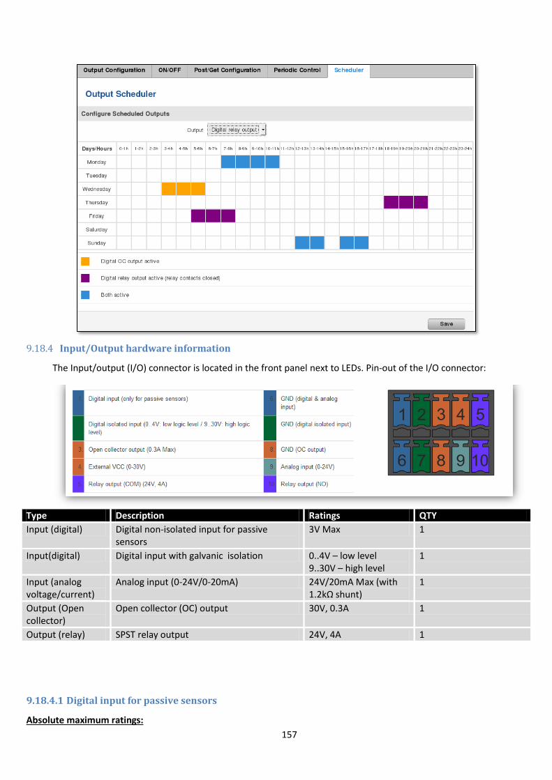
157
9.18.4 Input/Output hardware information
The Input/output (I/O) connector is located in the front panel next to LEDs. Pin-out of the I/O connector:
Type Description Ratings QTY
Input (digital) Digital non-isolated input for passive sensors
3V Max 1
Input(digital) Digital input with galvanic isolation 0..4V – low level 9..30V – high level
1
Input (analog voltage/current)
Analog input (0-24V/0-20mA) 24V/20mA Max (with 1.2kΩ shunt)
1
Output (Open collector)
Open collector (OC) output 30V, 0.3A 1
Output (relay) SPST relay output 24V, 4A 1
9.18.4.1 Digital input for passive sensors
Absolute maximum ratings:
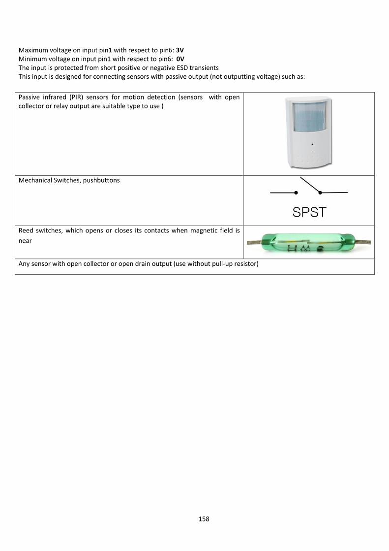
158
Maximum voltage on input pin1 with respect to pin6: 3V Minimum voltage on input pin1 with respect to pin6: 0V The input is protected from short positive or negative ESD transients This input is designed for connecting sensors with passive output (not outputting voltage) such as:
Passive infrared (PIR) sensors for motion detection (sensors with open collector or relay output are suitable type to use )
Mechanical Switches, pushbuttons
Reed switches, which opens or closes its contacts when magnetic field is
near
Any sensor with open collector or open drain output (use without pull-up resistor)
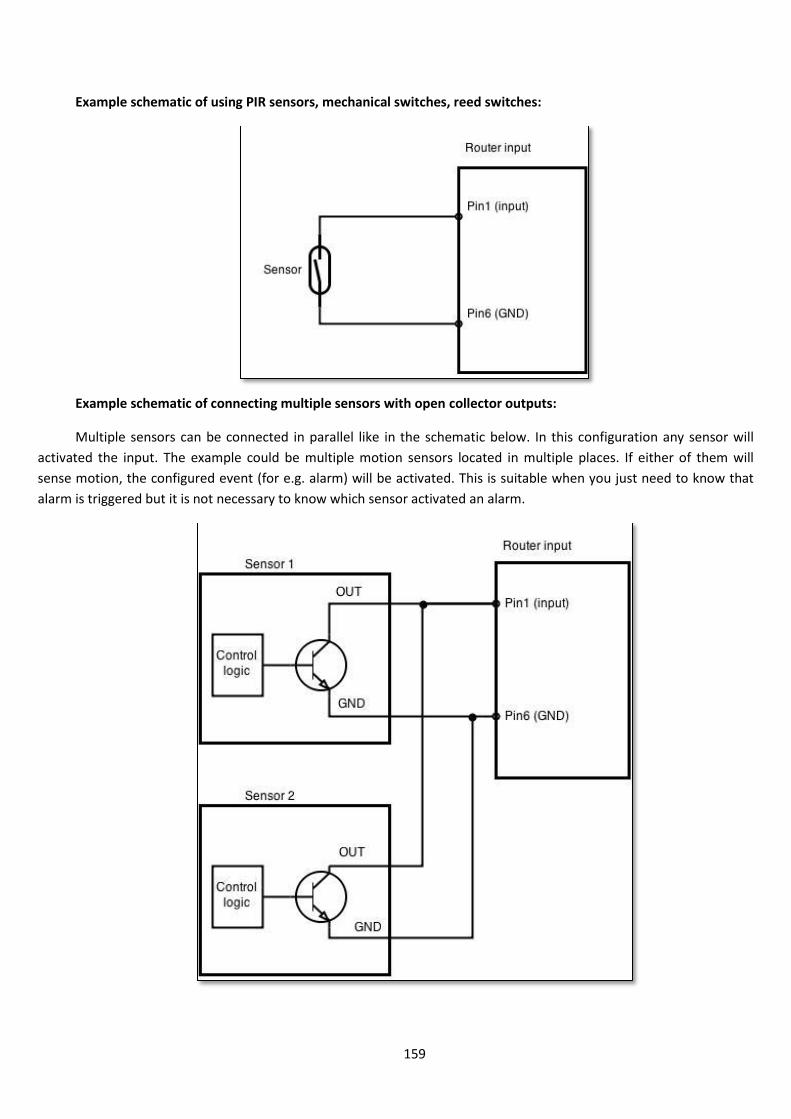
159
Example schematic of using PIR sensors, mechanical switches, reed switches:
Example schematic of connecting multiple sensors with open collector outputs:
Multiple sensors can be connected in parallel like in the schematic below. In this configuration any sensor will
activated the input. The example could be multiple motion sensors located in multiple places. If either of them will
sense motion, the configured event (for e.g. alarm) will be activated. This is suitable when you just need to know that
alarm is triggered but it is not necessary to know which sensor activated an alarm.

160
9.18.4.2 Digital galvanically isolated input
Sensors with push-pull output stage can be connected to this input. Example of such circuit is shown in the
picture below. The circuit uses optocoupler to isolate the input. In case of the failure at the input, the rest of the circuit
remains safe.
The signal source resistance should be less than 100Ω.
Input voltage levels:
Low level voltage: 0..+4V
High level voltage: +9..30V
Maximum ratings:
Maximum voltage that can be connected to pin2 with respect to pin7 is 30V. Do not exceed this voltage!
The input is protected from reverse voltage down to -200V.
9.18.4.3 Analog input
Analog input is designed to measure analog voltages in the range of 0-24V and convert it to digital domain. This
input can also be used to measure current up to 20mA.
Example of monitoring 12V battery voltage:
When Analog input type is „Analog Current“ a 1.2kΩ resistor shunt must be connected as shown below:

161
Input electrical characteristics:
Parameter Value
Maximum voltage 24V
Minimum voltage 0V
Resolution 5.859mV
Input low-pass filter cut-off frequency (-3dB) 10Hz
Input resistance (seen between I/O header pins 9 and 6 ) 131kΩ
Input accuracy:
Input voltage range, V Measurement error, %
0 <Vin≤ 1 <20
1 <Vin≤ 2 <10
2 <Vin≤ 5 <5
5 <Vin≤ 24 <3
9.18.4.4 Open collector output
This output can be used to drive external relay. In order for the output to work correctly, external voltage that is
connected to a relay also needs to be connected to I/O header pin 4. There is flyback diode located inside the device to
protect it from spikes occurring when inductive load (relay coil) is suddenly switched off, so connection of the external
diode is not necessary. The output is isolated from the rest of the circuitry using optocoupler. In case of the output
failure, the rest of the circuit will remain protected.
Maximum external DC voltage 30V
Maximum output sink current 0.3A
Example of driving a relay:
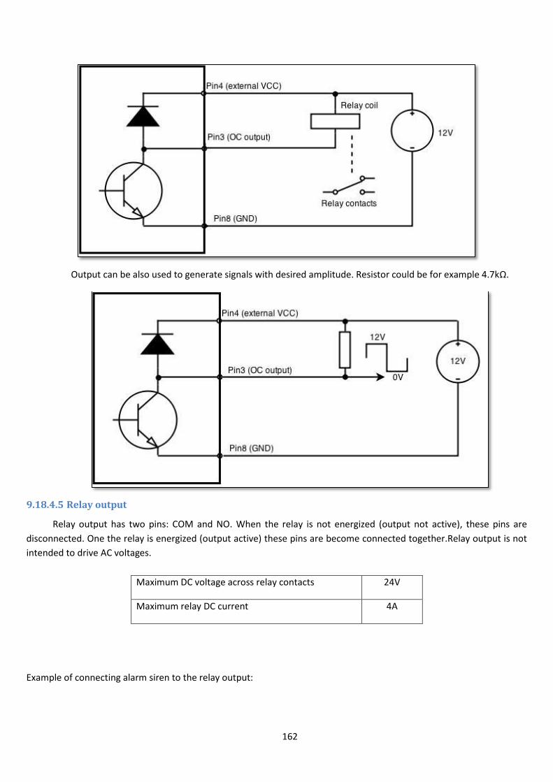
162
Output can be also used to generate signals with desired amplitude. Resistor could be for example 4.7kΩ.
9.18.4.5 Relay output
Relay output has two pins: COM and NO. When the relay is not energized (output not active), these pins are
disconnected. One the relay is energized (output active) these pins are become connected together.Relay output is not
intended to drive AC voltages.
Maximum DC voltage across relay contacts 24V
Maximum relay DC current 4A
Example of connecting alarm siren to the relay output:
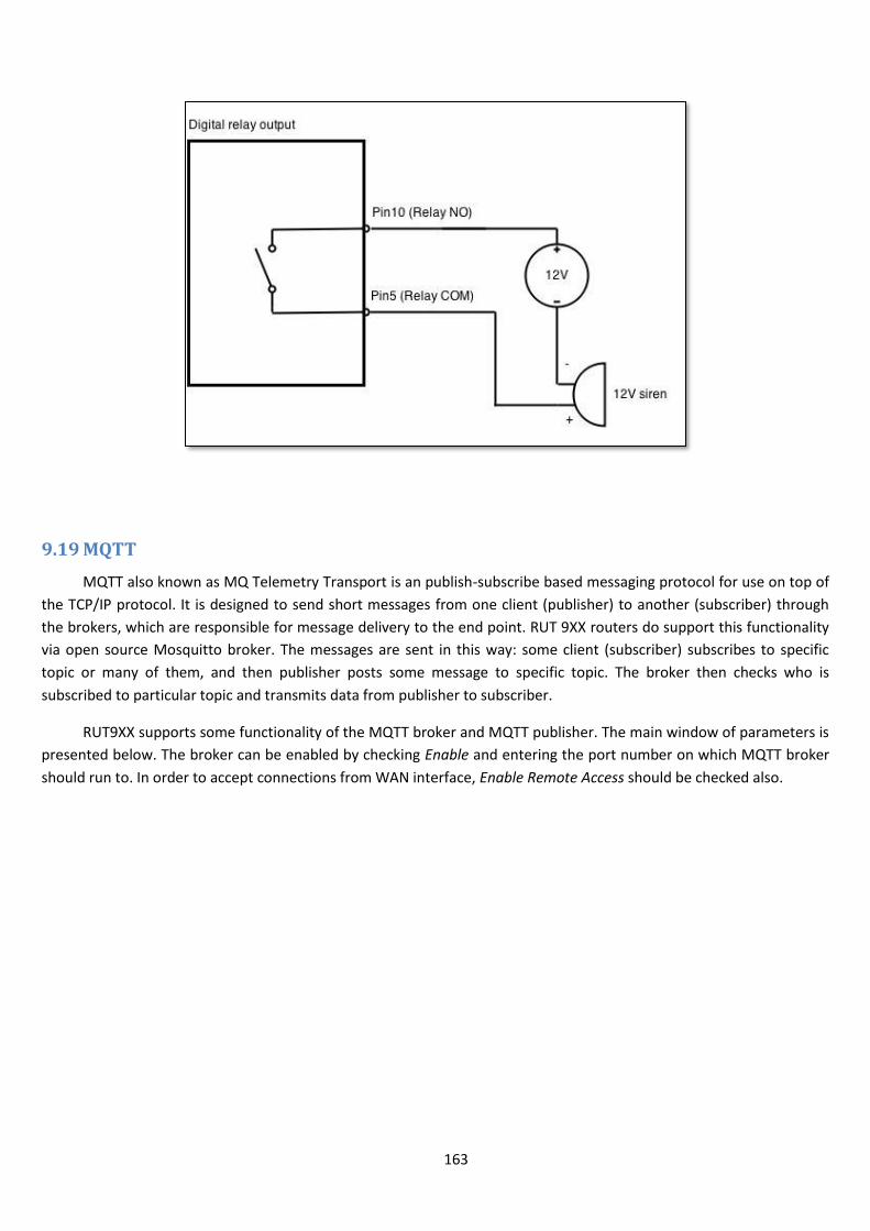
163
9.19 MQTT
MQTT also known as MQ Telemetry Transport is an publish-subscribe based messaging protocol for use on top of
the TCP/IP protocol. It is designed to send short messages from one client (publisher) to another (subscriber) through
the brokers, which are responsible for message delivery to the end point. RUT 9XX routers do support this functionality
via open source Mosquitto broker. The messages are sent in this way: some client (subscriber) subscribes to specific
topic or many of them, and then publisher posts some message to specific topic. The broker then checks who is
subscribed to particular topic and transmits data from publisher to subscriber.
RUT9XX supports some functionality of the MQTT broker and MQTT publisher. The main window of parameters is
presented below. The broker can be enabled by checking Enable and entering the port number on which MQTT broker
should run to. In order to accept connections from WAN interface, Enable Remote Access should be checked also.
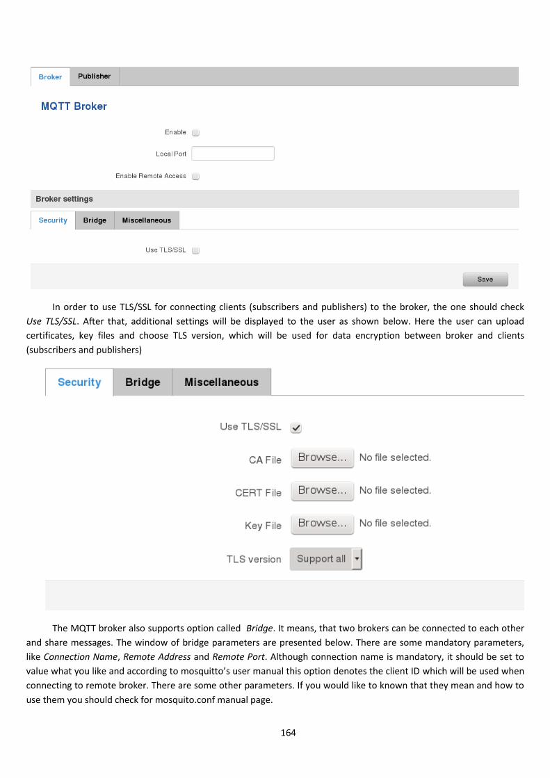
164
In order to use TLS/SSL for connecting clients (subscribers and publishers) to the broker, the one should check
Use TLS/SSL. After that, additional settings will be displayed to the user as shown below. Here the user can upload
certificates, key files and choose TLS version, which will be used for data encryption between broker and clients
(subscribers and publishers)
The MQTT broker also supports option called Bridge. It means, that two brokers can be connected to each other
and share messages. The window of bridge parameters are presented below. There are some mandatory parameters,
like Connection Name, Remote Address and Remote Port. Although connection name is mandatory, it should be set to
value what you like and according to mosquitto’s user manual this option denotes the client ID which will be used when
connecting to remote broker. There are some other parameters. If you would like to known that they mean and how to
use them you should check for mosquito.conf manual page.
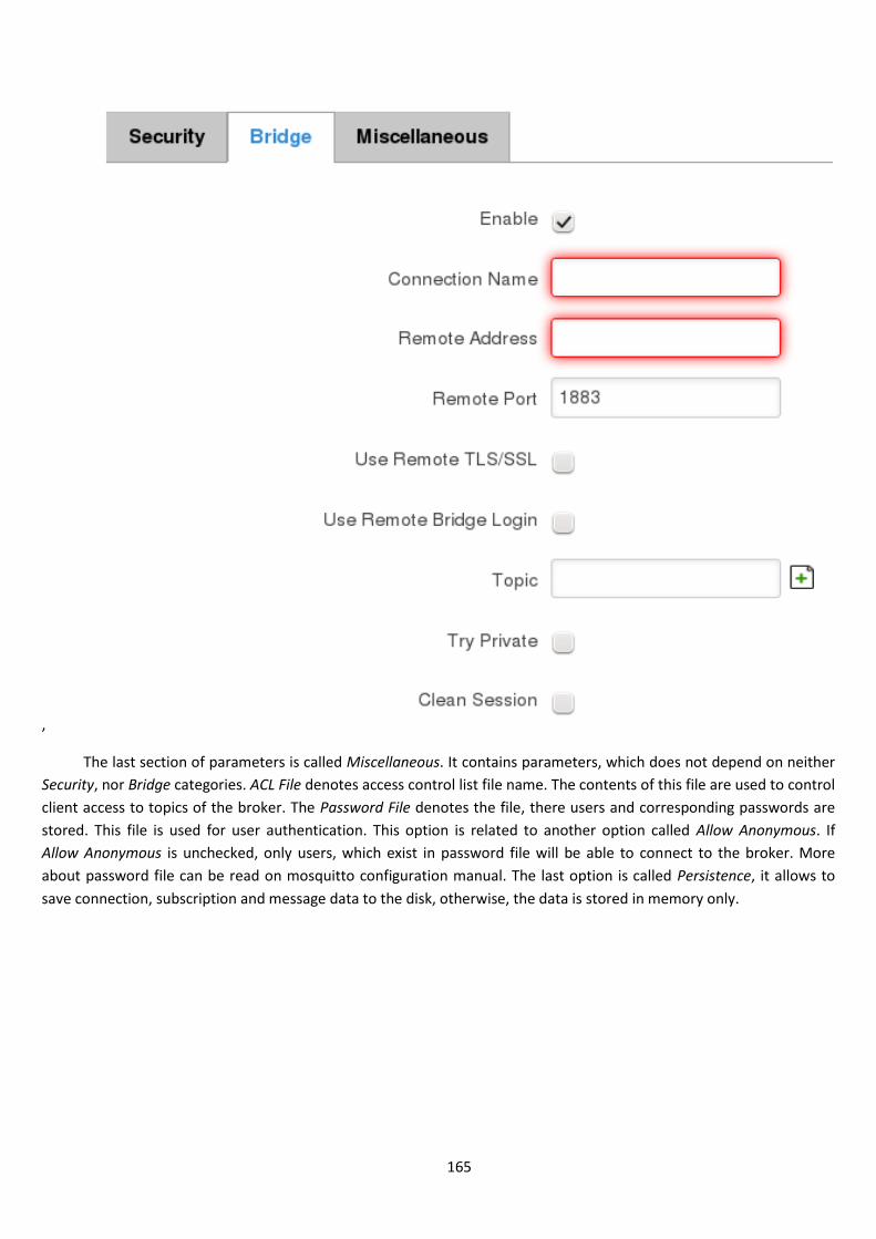
165
,
The last section of parameters is called Miscellaneous. It contains parameters, which does not depend on neither
Security, nor Bridge categories. ACL File denotes access control list file name. The contents of this file are used to control
client access to topics of the broker. The Password File denotes the file, there users and corresponding passwords are
stored. This file is used for user authentication. This option is related to another option called Allow Anonymous. If
Allow Anonymous is unchecked, only users, which exist in password file will be able to connect to the broker. More
about password file can be read on mosquitto configuration manual. The last option is called Persistence, it allows to
save connection, subscription and message data to the disk, otherwise, the data is stored in memory only.
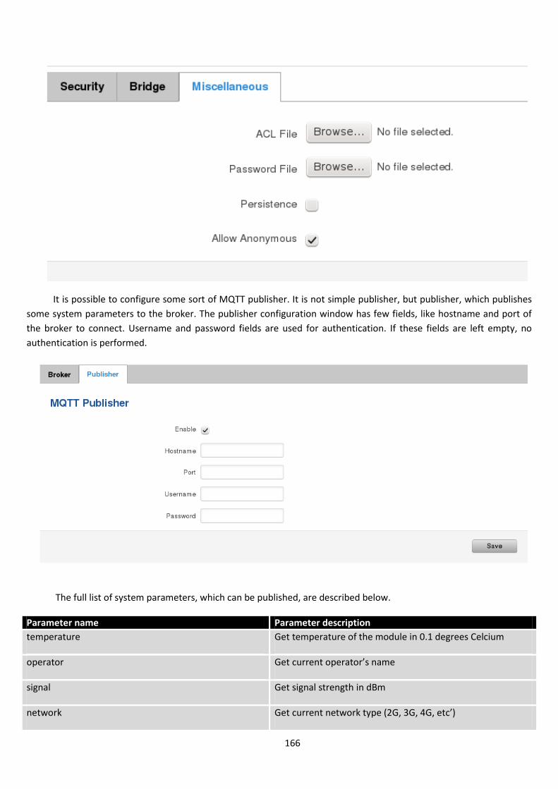
166
It is possible to configure some sort of MQTT publisher. It is not simple publisher, but publisher, which publishes
some system parameters to the broker. The publisher configuration window has few fields, like hostname and port of
the broker to connect. Username and password fields are used for authentication. If these fields are left empty, no
authentication is performed.
The full list of system parameters, which can be published, are described below.
Parameter name Parameter description
temperature Get temperature of the module in 0.1 degrees Celcium
operator Get current operator’s name
signal Get signal strength in dBm
network Get current network type (2G, 3G, 4G, etc’)
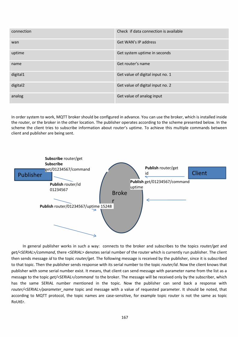
167
connection Check if data connection is available
wan Get WAN’s IP address
uptime Get system uptime in seconds
name Get router’s name
digital1 Get value of digital input no. 1
digital2 Get value of digital input no. 2
analog Get value of analog input
In order system to work, MQTT broker should be configured in advance. You can use the broker, which is installed inside the router, or the broker in the other location. The publisher operates according to the scheme presented below. In the scheme the client tries to subscribe information about router’s uptime. To achieve this multiple commands between client and publisher are being sent.
In general publisher works in such a way: connects to the broker and subscribes to the topics router/get and
get/<SERIAL>/command, there <SERIAL> denotes serial number of the router which is currently run publisher. The client
then sends message id to the topic router/get. The following message is received by the publisher, since it is subscribed
to that topic. Then the publisher sends response with its serial number to the topic router/id. Now the client knows that
publisher with some serial number exist. It means, that client can send message with parameter name from the list as a
message to the topic get/<SERIAL>/command to the broker. The message will be received only by the subscriber, which
has the same SERIAL number mentioned in the topic. Now the publisher can send back a response with
router/<SERIAL>/parameter_name topic and message with a value of requested parameter. It should be noted, that
according to MQTT protocol, the topic names are case-sensitive, for example topic router is not the same as topic
RoUtEr.
Publisher
Subscribe router/get Subscribe get/01234567/command Publish router/get
id
Publish router/id 01234567
Publish get/01234567/command uptime
Broker
Client
Publish router/01234567/uptime 15248
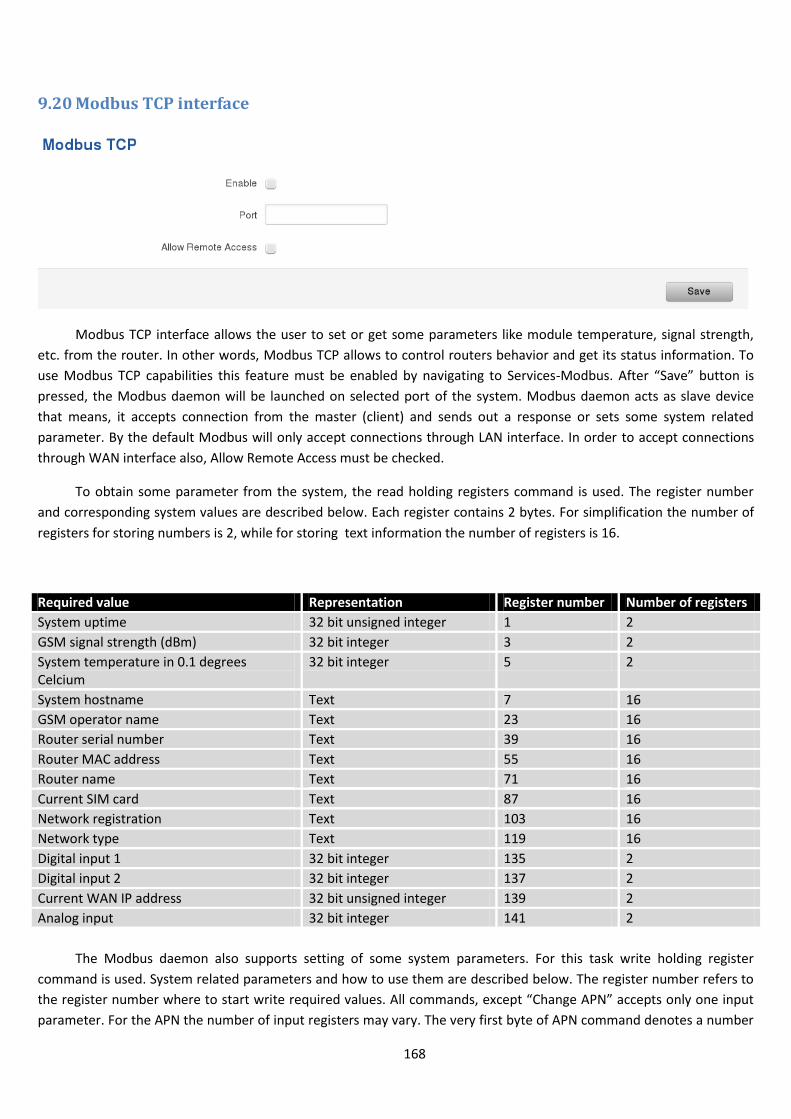
168
9.20 Modbus TCP interface
Modbus TCP interface allows the user to set or get some parameters like module temperature, signal strength,
etc. from the router. In other words, Modbus TCP allows to control routers behavior and get its status information. To
use Modbus TCP capabilities this feature must be enabled by navigating to Services-Modbus. After “Save” button is
pressed, the Modbus daemon will be launched on selected port of the system. Modbus daemon acts as slave device
that means, it accepts connection from the master (client) and sends out a response or sets some system related
parameter. By the default Modbus will only accept connections through LAN interface. In order to accept connections
through WAN interface also, Allow Remote Access must be checked.
To obtain some parameter from the system, the read holding registers command is used. The register number
and corresponding system values are described below. Each register contains 2 bytes. For simplification the number of
registers for storing numbers is 2, while for storing text information the number of registers is 16.
Required value Representation Register number Number of registers
System uptime 32 bit unsigned integer 1 2
GSM signal strength (dBm) 32 bit integer 3 2
System temperature in 0.1 degrees Celcium
32 bit integer 5 2
System hostname Text 7 16
GSM operator name Text 23 16
Router serial number Text 39 16
Router MAC address Text 55 16
Router name Text 71 16
Current SIM card Text 87 16
Network registration Text 103 16
Network type Text 119 16
Digital input 1 32 bit integer 135 2
Digital input 2 32 bit integer 137 2
Current WAN IP address 32 bit unsigned integer 139 2
Analog input 32 bit integer 141 2
The Modbus daemon also supports setting of some system parameters. For this task write holding register
command is used. System related parameters and how to use them are described below. The register number refers to
the register number where to start write required values. All commands, except “Change APN” accepts only one input
parameter. For the APN the number of input registers may vary. The very first byte of APN command denotes a number
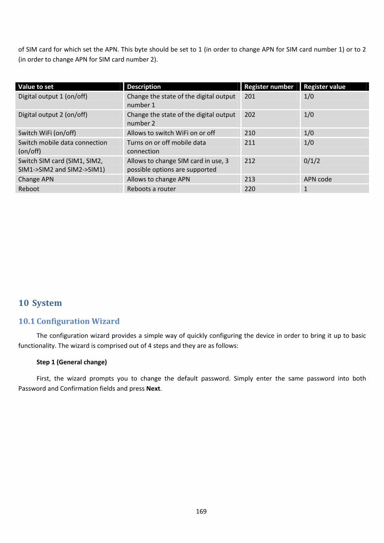
169
of SIM card for which set the APN. This byte should be set to 1 (in order to change APN for SIM card number 1) or to 2
(in order to change APN for SIM card number 2).
Value to set Description Register number Register value
Digital output 1 (on/off) Change the state of the digital output number 1
201 1/0
Digital output 2 (on/off) Change the state of the digital output number 2
202 1/0
Switch WiFi (on/off) Allows to switch WiFi on or off 210 1/0
Switch mobile data connection (on/off)
Turns on or off mobile data connection
211 1/0
Switch SIM card (SIM1, SIM2, SIM1->SIM2 and SIM2->SIM1)
Allows to change SIM card in use, 3 possible options are supported
212 0/1/2
Change APN Allows to change APN 213 APN code
Reboot Reboots a router 220 1
10 System
10.1 Configuration Wizard
The configuration wizard provides a simple way of quickly configuring the device in order to bring it up to basic
functionality. The wizard is comprised out of 4 steps and they are as follows:
Step 1 (General change)
First, the wizard prompts you to change the default password. Simply enter the same password into both
Password and Confirmation fields and press Next.
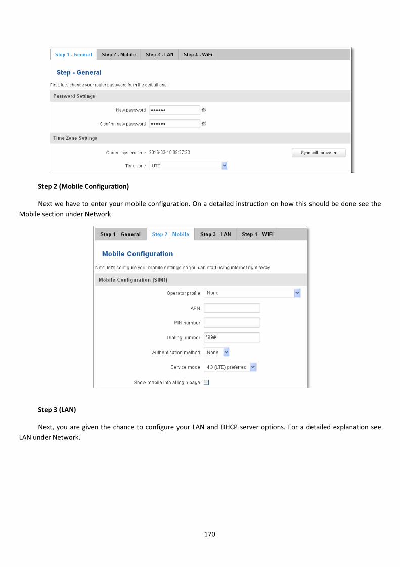
170
Step 2 (Mobile Configuration)
Next we have to enter your mobile configuration. On a detailed instruction on how this should be done see the
Mobile section under Network
Step 3 (LAN)
Next, you are given the chance to configure your LAN and DHCP server options. For a detailed explanation see
LAN under Network.
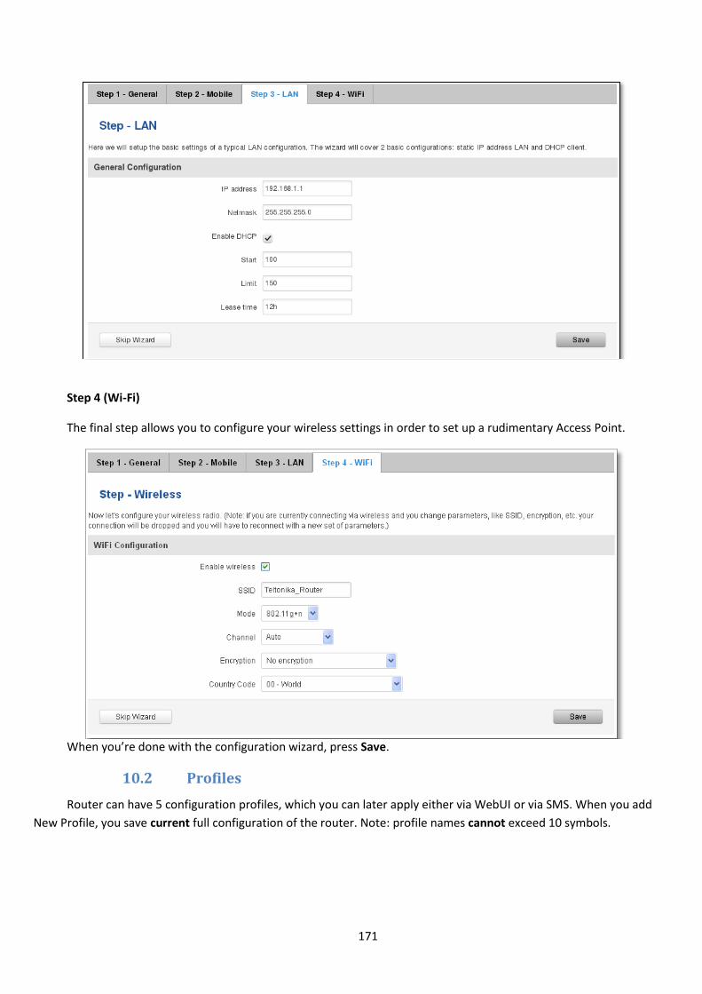
171
Step 4 (Wi-Fi)
The final step allows you to configure your wireless settings in order to set up a rudimentary Access Point.
When you’re done with the configuration wizard, press Save.
10.2 Profiles
Router can have 5 configuration profiles, which you can later apply either via WebUI or via SMS. When you add
New Profile, you save current full configuration of the router. Note: profile names cannot exceed 10 symbols.
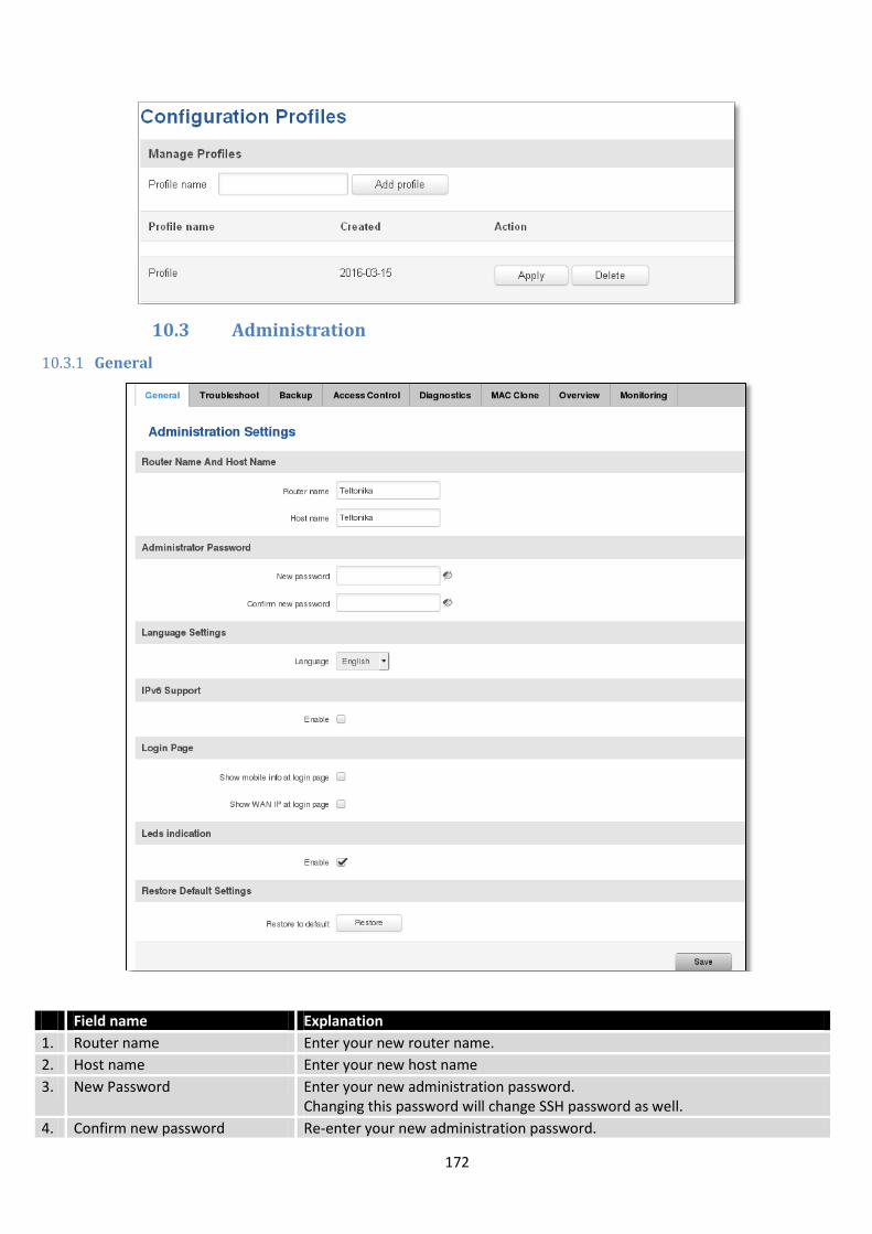
172
10.3 Administration
10.3.1 General
Field name Explanation
1. Router name Enter your new router name.
2. Host name Enter your new host name
3. New Password Enter your new administration password. Changing this password will change SSH password as well.
4. Confirm new password Re-enter your new administration password.
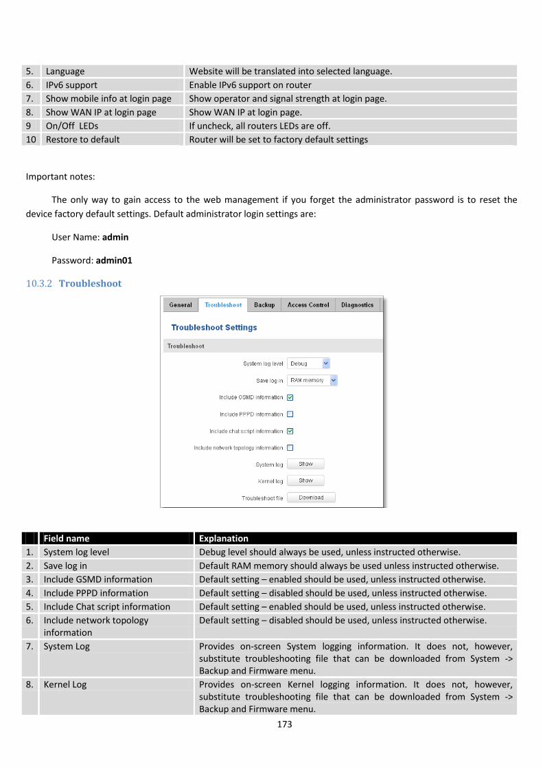
173
5. Language Website will be translated into selected language.
6. IPv6 support Enable IPv6 support on router
7. Show mobile info at login page Show operator and signal strength at login page.
8. Show WAN IP at login page Show WAN IP at login page.
9 On/Off LEDs If uncheck, all routers LEDs are off.
10 Restore to default Router will be set to factory default settings
Important notes:
The only way to gain access to the web management if you forget the administrator password is to reset the
device factory default settings. Default administrator login settings are:
User Name: admin
Password: admin01
10.3.2 Troubleshoot
Field name Explanation
1. System log level Debug level should always be used, unless instructed otherwise.
2. Save log in Default RAM memory should always be used unless instructed otherwise.
3. Include GSMD information Default setting – enabled should be used, unless instructed otherwise.
4. Include PPPD information Default setting – disabled should be used, unless instructed otherwise.
5. Include Chat script information Default setting – enabled should be used, unless instructed otherwise.
6. Include network topology information
Default setting – disabled should be used, unless instructed otherwise.
7. System Log Provides on-screen System logging information. It does not, however, substitute troubleshooting file that can be downloaded from System -> Backup and Firmware menu.
8. Kernel Log Provides on-screen Kernel logging information. It does not, however, substitute troubleshooting file that can be downloaded from System -> Backup and Firmware menu.

174
9. Troubleshoot file Downloadable archive, that contains full router configuration and all System log files.
10.3.3 Backup
Field name Explanation
1. Backup archive Download current router settings file to personal computer. This file can be loaded to other RUT955 with same Firmware version in order to quickly configure it.
2. Restore from backup Select, upload and restore router settings file from personal computer.
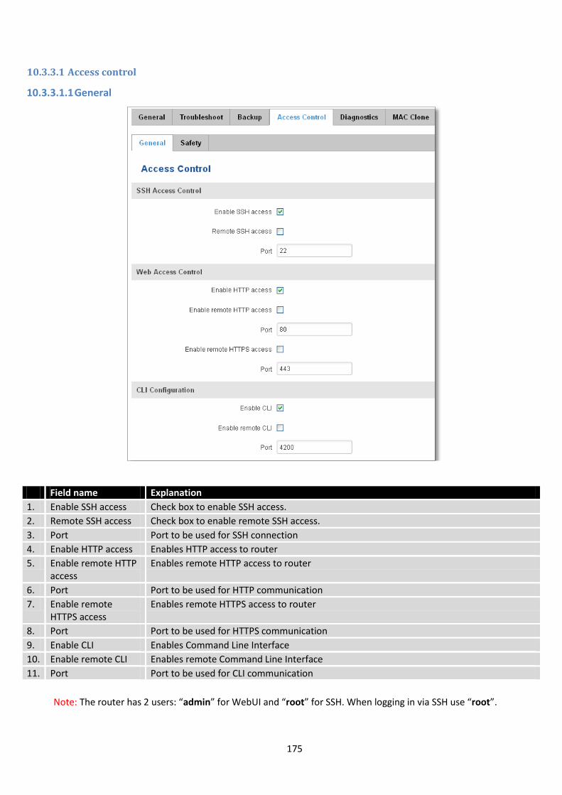
175
10.3.3.1 Access control
10.3.3.1.1 General
Field name Explanation
1. Enable SSH access Check box to enable SSH access.
2. Remote SSH access Check box to enable remote SSH access.
3. Port Port to be used for SSH connection
4. Enable HTTP access Enables HTTP access to router
5. Enable remote HTTP access
Enables remote HTTP access to router
6. Port Port to be used for HTTP communication
7. Enable remote HTTPS access
Enables remote HTTPS access to router
8. Port Port to be used for HTTPS communication
9. Enable CLI Enables Command Line Interface
10. Enable remote CLI Enables remote Command Line Interface
11. Port Port to be used for CLI communication
Note: The router has 2 users: “admin” for WebUI and “root” for SSH. When logging in via SSH use “root”.
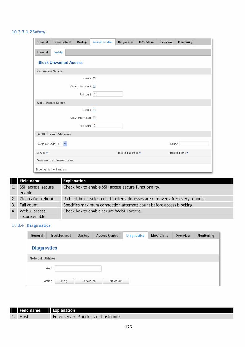
176
10.3.3.1.2 Safety
Field name Explanation
1. SSH access secure enable
Check box to enable SSH access secure functionality.
2. Clean after reboot If check box is selected – blocked addresses are removed after every reboot.
3. Fail count Specifies maximum connection attempts count before access blocking.
4. WebUI access secure enable
Check box to enable secure WebUI access.
10.3.4 Diagnostics
Field name Explanation
1. Host Enter server IP address or hostname.

177
2. Ping Utility used to test the reach ability of a host on an Internet IP network and to measure the round-trip time for messages sent from the originating host to a destination server. Server echo response will be shown after few seconds if server is accessible.
3. Traceroute Diagnostics tool for displaying the route (path) and measuring transit delays of packets across an
Internet IP network. Log containing route information will be shown after few seconds.
4. Nslookup Network administration command-line tool for querying the Domain Name System (DNS) to obtain domain name or IP address mapping or for any other specific DNS record. Log containing specified server DNS lookup information will be shown after few seconds.
10.3.5 MAC Clone
Field name Explanation
1. WAN MAC address Enter new WAN MAC address.
10.3.6 Overview
Select which information you want to get in Overview window (Status -> Overview).
Field name Explanation
1. Mobile Check box to show Mobile table in Overview page
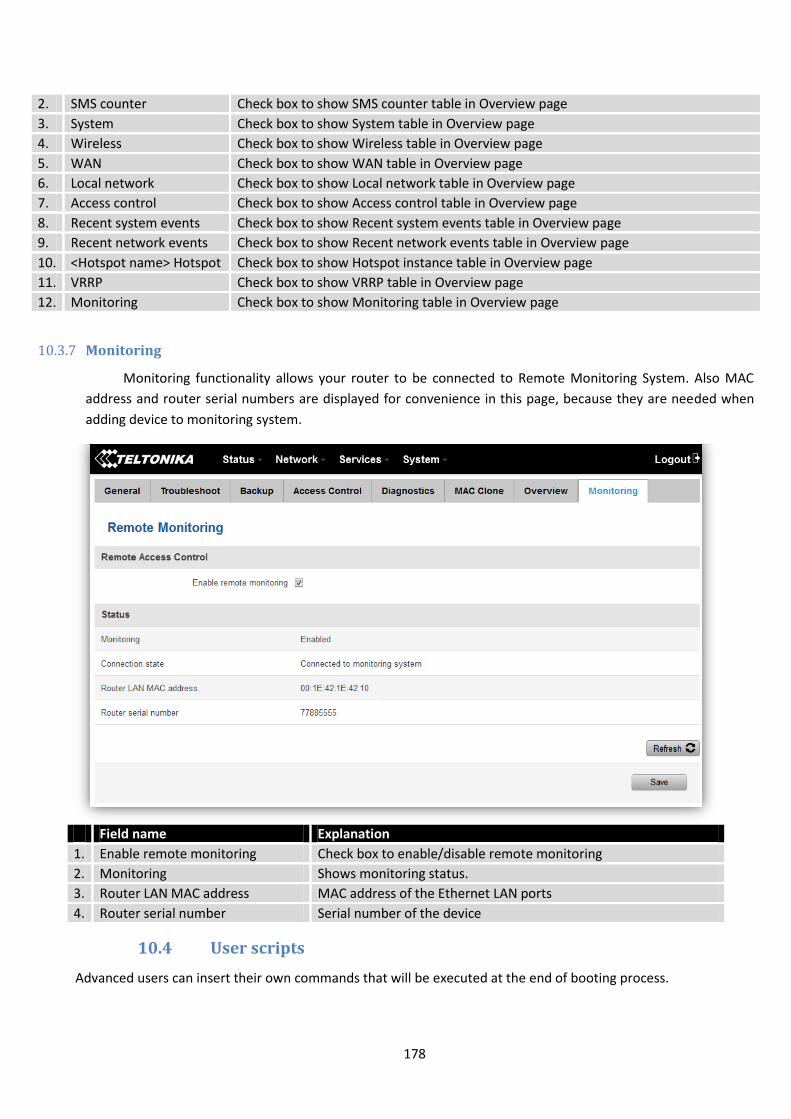
178
2. SMS counter Check box to show SMS counter table in Overview page
3. System Check box to show System table in Overview page
4. Wireless Check box to show Wireless table in Overview page
5. WAN Check box to show WAN table in Overview page
6. Local network Check box to show Local network table in Overview page
7. Access control Check box to show Access control table in Overview page
8. Recent system events Check box to show Recent system events table in Overview page
9. Recent network events Check box to show Recent network events table in Overview page
10. <Hotspot name> Hotspot Check box to show Hotspot instance table in Overview page
11. VRRP Check box to show VRRP table in Overview page
12. Monitoring Check box to show Monitoring table in Overview page
10.3.7 Monitoring
Monitoring functionality allows your router to be connected to Remote Monitoring System. Also MAC
address and router serial numbers are displayed for convenience in this page, because they are needed when
adding device to monitoring system.
Field name Explanation
1. Enable remote monitoring Check box to enable/disable remote monitoring
2. Monitoring Shows monitoring status.
3. Router LAN MAC address MAC address of the Ethernet LAN ports
4. Router serial number Serial number of the device
10.4 User scripts
Advanced users can insert their own commands that will be executed at the end of booting process.

179
In Script Management window is shown content of a file /etc/rc.local. This file is executed at the end of startup,
executing the line: sh /etc/rc.local In this script is needed to use sh (ash) commands. It should be noted, that this is
embedded device and sh functionality is not full.
10.5 Restore point
10.5.1 Restore point create
Allow to create firmware restore points with all custom configurations. You can download created restore points
to your computer.
10.5.2 Restore point load
Allow to restore configuration from previously saved restore point. You can upload restore point from your
computer.
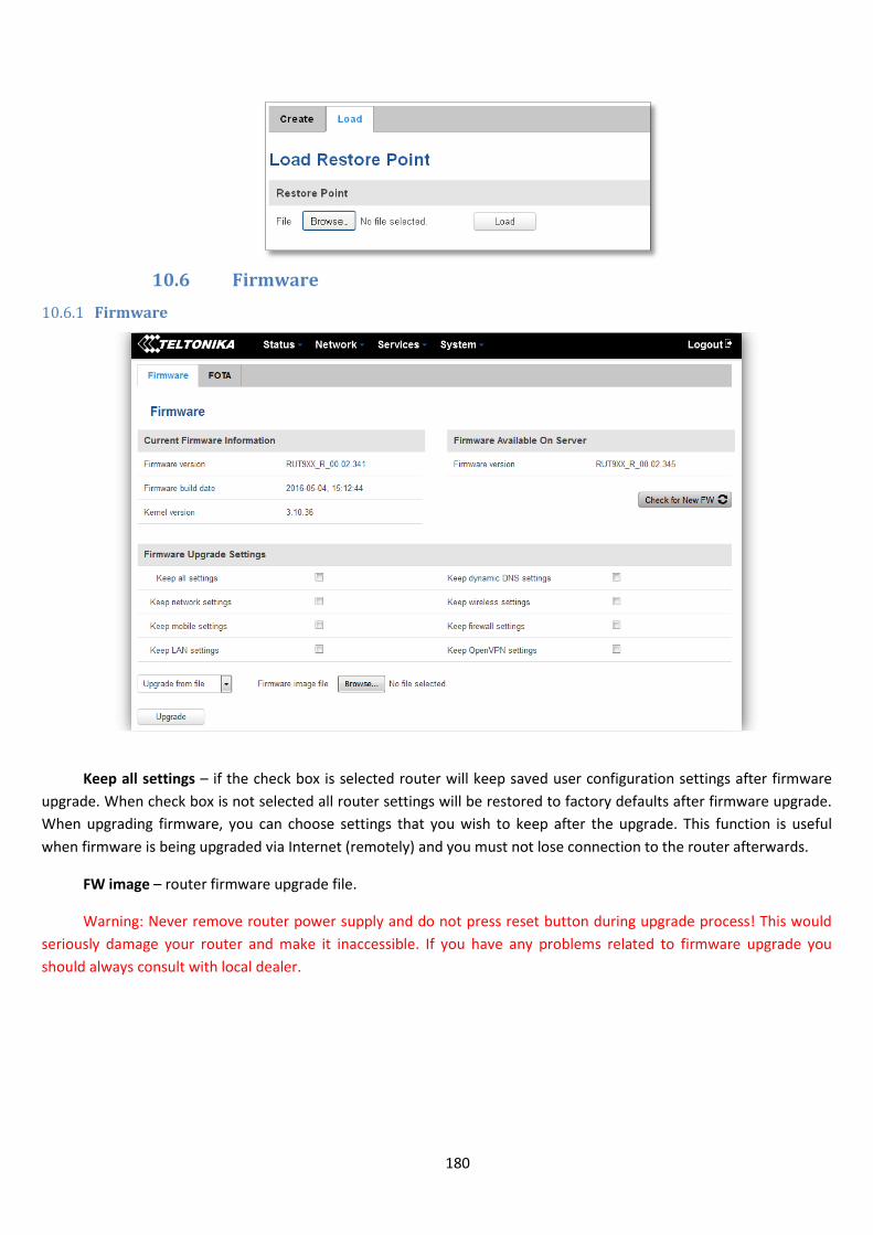
180
10.6 Firmware
10.6.1 Firmware
Keep all settings – if the check box is selected router will keep saved user configuration settings after firmware
upgrade. When check box is not selected all router settings will be restored to factory defaults after firmware upgrade.
When upgrading firmware, you can choose settings that you wish to keep after the upgrade. This function is useful
when firmware is being upgraded via Internet (remotely) and you must not lose connection to the router afterwards.
FW image – router firmware upgrade file.
Warning: Never remove router power supply and do not press reset button during upgrade process! This would
seriously damage your router and make it inaccessible. If you have any problems related to firmware upgrade you
should always consult with local dealer.

181
10.6.2 FOTA
Field name Explanation
1. Server address Specify server address to check for firmware updates. E.g. “http://teltonika.sritis.lt/rut9xx_auto_update/clients/”
2. User name User name for server authorization.
3. Password Password name for server authorization.
4. Enable auto check Check box to enable automatic checking for new firmware updates.
5. Auto check mode Select when to perform auto check function.
6. WAN wired Allows to update firmware from server only if routers WAN is wired (if box is checked).
10.7 Reboot
Reboot router by pressing button “Reboot”.
11 Device Recovery
The following section describes available options for recovery of malfunctioning device. Usually device can
become unreachable due to power failure during firmware upgrade or if its core files were wrongly modified in the file
system. Teltonika’s routers offer several options for recovering from these situations.
182
11.1 Reset button
Reset button is located on the back panel of the device. Reset button has several functions:
Reboot the device. After the device has started and if the reset button is pressed for up to 4 seconds the device
will reboot. Start of the reboot will be indicated by flashing of all 5 signal strength LEDs together with green connection
status LED.
Reset to defaults. After the device has started if the reset button is pressed for at least 5 seconds the device will
reset all user changes to factory defaults and reboot. To help user to determine how long the reset button should be
pressed, signal strength LEDs indicates the elapsed time. All 5 lit LEDs means that 5 seconds have passed and reset
button can be released. Start of the reset to defaults will be indicated by flashing of all 5 signal strength LEDs together
with red connection status LED. SIM PIN on the main SIM card is the only user parameter that is kept after reset to
defaults.
11.2 Bootloader’s WebUI
Bootloader also provides a way to recover the router functionality when the firmware is damaged. To make it
easier to use bootloader has its own webserver that can be accessed with any web browser.
Procedure for starting bootloader’s webserver:
Automatically. It happens when bootloader does not detect master firmware. Flashing all 4 Ethernet LEDs
indicate that bootloader’s webserver has started.
Manually. Bootloader’s webserver can be requested by holding reset button for 3 seconds while powering the
device on. Flashing all 4 Ethernet LEDs indicates that bootloader’s webserver has started.
Bootloader’s WebUI can be accessed by typing this address in the web browser:
http://192.168.1.1/index.html
Note: it may be necessary to clear web browser’s cache and to use incognito/anonymous window to access
bootloader’s WebUI.
12 Glossary:
WAN – Wide Area Network is a telecommunication network that covers a broad area (i.e., any network that links
across metropolitan, regional, or national boundaries). Here we use the term WAN to mean the external network that
the router uses to reach the internet.
LAN – A local area network (LAN) is a computer network that interconnects computers in a limited area such as a
home, school, computer laboratory, or office building.
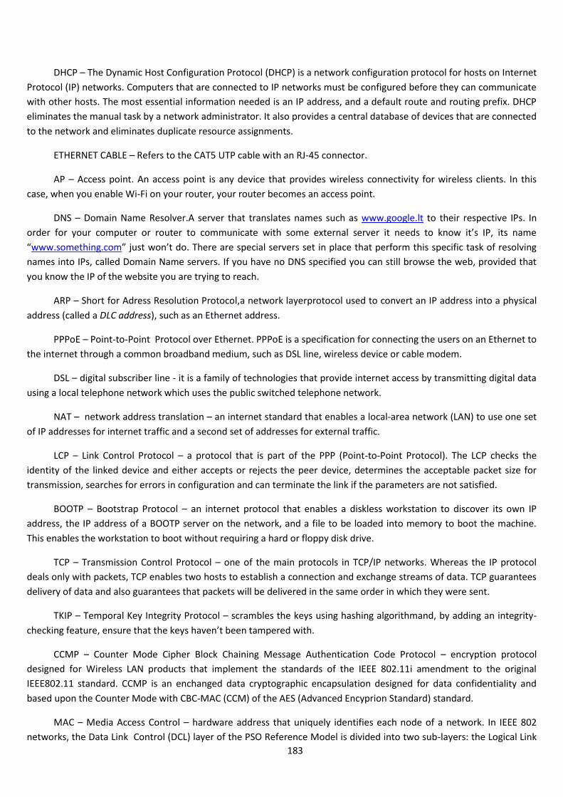
183
DHCP – The Dynamic Host Configuration Protocol (DHCP) is a network configuration protocol for hosts on Internet
Protocol (IP) networks. Computers that are connected to IP networks must be configured before they can communicate
with other hosts. The most essential information needed is an IP address, and a default route and routing prefix. DHCP
eliminates the manual task by a network administrator. It also provides a central database of devices that are connected
to the network and eliminates duplicate resource assignments.
ETHERNET CABLE – Refers to the CAT5 UTP cable with an RJ-45 connector.
AP – Access point. An access point is any device that provides wireless connectivity for wireless clients. In this
case, when you enable Wi-Fi on your router, your router becomes an access point.
DNS – Domain Name Resolver.A server that translates names such as www.google.lt to their respective IPs. In
order for your computer or router to communicate with some external server it needs to know it’s IP, its name
“www.something.com” just won’t do. There are special servers set in place that perform this specific task of resolving
names into IPs, called Domain Name servers. If you have no DNS specified you can still browse the web, provided that
you know the IP of the website you are trying to reach.
ARP – Short for Adress Resolution Protocol,a network layerprotocol used to convert an IP address into a physical
address (called a DLC address), such as an Ethernet address.
PPPoE – Point-to-Point Protocol over Ethernet. PPPoE is a specification for connecting the users on an Ethernet to
the internet through a common broadband medium, such as DSL line, wireless device or cable modem.
DSL – digital subscriber line - it is a family of technologies that provide internet access by transmitting digital data
using a local telephone network which uses the public switched telephone network.
NAT – network address translation – an internet standard that enables a local-area network (LAN) to use one set
of IP addresses for internet traffic and a second set of addresses for external traffic.
LCP – Link Control Protocol – a protocol that is part of the PPP (Point-to-Point Protocol). The LCP checks the
identity of the linked device and either accepts or rejects the peer device, determines the acceptable packet size for
transmission, searches for errors in configuration and can terminate the link if the parameters are not satisfied.
BOOTP – Bootstrap Protocol – an internet protocol that enables a diskless workstation to discover its own IP
address, the IP address of a BOOTP server on the network, and a file to be loaded into memory to boot the machine.
This enables the workstation to boot without requiring a hard or floppy disk drive.
TCP – Transmission Control Protocol – one of the main protocols in TCP/IP networks. Whereas the IP protocol
deals only with packets, TCP enables two hosts to establish a connection and exchange streams of data. TCP guarantees
delivery of data and also guarantees that packets will be delivered in the same order in which they were sent.
TKIP – Temporal Key Integrity Protocol – scrambles the keys using hashing algorithmand, by adding an integrity-
checking feature, ensure that the keys haven’t been tampered with.
CCMP – Counter Mode Cipher Block Chaining Message Authentication Code Protocol – encryption protocol
designed for Wireless LAN products that implement the standards of the IEEE 802.11i amendment to the original
IEEE802.11 standard. CCMP is an enchanged data cryptographic encapsulation designed for data confidentiality and
based upon the Counter Mode with CBC-MAC (CCM) of the AES (Advanced Encyprion Standard) standard.
MAC – Media Access Control – hardware address that uniquely identifies each node of a network. In IEEE 802
networks, the Data Link Control (DCL) layer of the PSO Reference Model is divided into two sub-layers: the Logical Link
184
Control (LLC) layer and the Media Access Control layer. The MAC layer interfaces directly with the network medium.
Consequently, each different type of network medium requires a different MAC layer.
DMZ – Demilitarized Zone – a computer or small subnetwork that sits between a trusted internal network, such as
a corporate private LAN, and an untrusted external network, such as the public internet.
UDP – User Datagram Protocol – a connectionless protocol that, like TCP, runs on top of IP networks. Provides
very few error recovery services, offering instead a direct way to send and receive datagrams over IP network.
VPN – Virtual Private Network – a network that is constructed by using public wires — usually the Internet — to
connect to a private network, such as a company's internal network.
VRRP – Virtual Router Redundancy Protocol - an election protocol that dynamically assigns responsibility for one
or more virtual router(s) to the VRRP router(s) on a LAN, allowing several routers on a multiaccess link to utilize the
same virtual IP address.
GRE Tunnel – Generic Routing Encapsulation - a tunneling protocol developed by Cisco Systems that can
encapsulate a wide variety of network layerprotocols inside virtual point-to-point links over an Internet Protocol
internetwork.
PPPD – Point to Point Protocol Daemon – it is used to manage network connections between two nodes on Unix-
likeoperating systems. It is configured using command-line arguments and configuration files.
SSH – Secure SHell - a program to log into another computer over a network, to execute commands in a remote
machine, and to move files from one machine to another. It provides strong authentication and secure communications
over insecure channels.
VRRPD – Virtual Router Redundancy Protocol – it is designed to eliminate the single point of failure associated
with statically routed networks by automatically providing failover using multiple LAN paths through alternate routers.
SNMP – Simple Network Management Protocol - a set of protocols for managing complex networks. SNMP works
by sending messages, called protocol data units (PDUs), to different parts of a network.
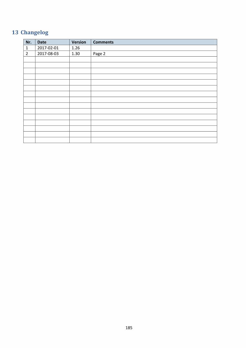
185
13 Changelog
Nr. Date Version Comments
1 2017-02-01 1.26
2 2017-08-03 1.30 Page 2