![Ampli cateur audio de classe D - f-legrand.fr€¦ · Ampli cateur audio de classe D 1. Introduction Ce document décrit la réalisation d'un ampli cateur audio de classe D ([1]),](https://static.fdocuments.us/doc/165x107/61072f6c7cf27371ea366aef/ampli-cateur-audio-de-classe-d-f-ampli-cateur-audio-de-classe-d-1-introduction.jpg)
User manual - Linköping University · User manual Modeling and control ... 3 Simulation 4 3.1 User...
18
User manual Modeling and control of an industrial robot Version 1.0 Author: AG, VI Date: November 25, 2011 Status Reviewed Alexander Pettersson 2011-11-25 Approved Patrik Axelsson 2011-11-25 Course name: Control Project Laboratory E-mail: [email protected] Project group: Industrial robot Document responsible: AG, VI Course code: TSRT10 Author’s E-mail: [email protected] Project: Industrial robot Document name: user manual.pdf
Transcript of User manual - Linköping University · User manual Modeling and control ... 3 Simulation 4 3.1 User...
User manualModeling and control of an industrial robot
Version 1.0
Author: AG, VIDate: November 25, 2011
Status
Reviewed Alexander Pettersson 2011-11-25Approved Patrik Axelsson 2011-11-25
Course name: Control Project Laboratory E-mail: [email protected] group: Industrial robot Document responsible: AG, VICourse code: TSRT10 Author’s E-mail: [email protected]: Industrial robot Document name: user manual.pdf

Project Identity
Group E-mail: [email protected]: http://www.isy.liu.se/edu/projekt/reglerteknik/2011/industrirobot/Orderer: Patrik Axelsson, Linkoping University
Phone: 013 284474, E-mail: [email protected]: Mikael Norrlof, ABB Robotics
Phone: 021 346017 , E-mail: [email protected] Sjoberg, ABB Corporate ResearchPhone: 013 284028 , E-mail: [email protected]
Course Responsible: David Tornqvist, Linkoping UniversityPhone: 013 281882, E-mail: [email protected] Axehill, Linkoping UniversityPhone: 013 284042, E-mail: [email protected]
Project Manager: Tobias AnderssonAdvisors: Andre Carvalho Bittencourt, Linkoping University
Phone: 013 282622 , E-mail: [email protected]
Group Members
Name Responsibility Phone E-mail(@student.liu.se)
Tobias Andersson (TA) Project manager 0730530440 toban607Alexander Pettersson (AP) Documents 0737767682 alepe490Jonas Kallman (JK) Design 0739575719 jonka615Victor Ingestrom (VI) Mechanical modeling 0704926973 vicin977Kristofer Klasson (KK) Tests 0738184392 krikl150Gabriella Ahlbert (GA) Information 0705911501 gabah362Andreas Samuelsson (AS) 0730651177 andsa897Anders Gallsjo (AG) 0733681099 andga726
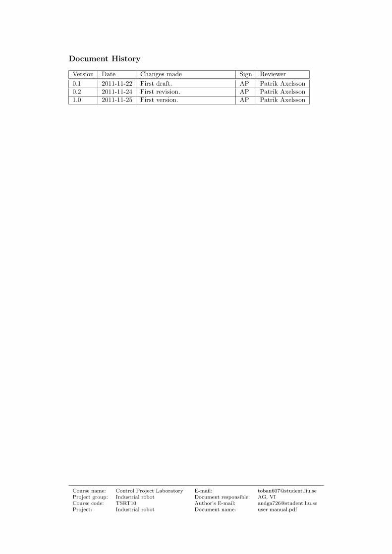
Document History
Version Date Changes made Sign Reviewer
0.1 2011-11-22 First draft. AP Patrik Axelsson0.2 2011-11-24 First revision. AP Patrik Axelsson1.0 2011-11-25 First version. AP Patrik Axelsson
Course name: Control Project Laboratory E-mail: [email protected] group: Industrial robot Document responsible: AG, VICourse code: TSRT10 Author’s E-mail: [email protected]: Industrial robot Document name: user manual.pdf
Contents
1 Introduction 1
2 Hardware 2
2.1 Coordinate System . . . . . . . . . . . . . . . . . . . . . . . . . . . . . . . . . . . . . . . . 2
2.2 Robot Setup . . . . . . . . . . . . . . . . . . . . . . . . . . . . . . . . . . . . . . . . . . . 2
3 Simulation 4
3.1 User interface . . . . . . . . . . . . . . . . . . . . . . . . . . . . . . . . . . . . . . . . . . . 4
3.2 Joint control . . . . . . . . . . . . . . . . . . . . . . . . . . . . . . . . . . . . . . . . . . . 5
3.3 Trajectory control . . . . . . . . . . . . . . . . . . . . . . . . . . . . . . . . . . . . . . . . 5
3.4 Starting the simulation . . . . . . . . . . . . . . . . . . . . . . . . . . . . . . . . . . . . . . 6
4 Controller program 8
4.1 Defining the default position . . . . . . . . . . . . . . . . . . . . . . . . . . . . . . . . . . 8
4.2 User interface . . . . . . . . . . . . . . . . . . . . . . . . . . . . . . . . . . . . . . . . . . . 11
4.3 Manual mode . . . . . . . . . . . . . . . . . . . . . . . . . . . . . . . . . . . . . . . . . . . 11
4.4 Automatic mode . . . . . . . . . . . . . . . . . . . . . . . . . . . . . . . . . . . . . . . . . 11
4.4.1 Trajectory OFF . . . . . . . . . . . . . . . . . . . . . . . . . . . . . . . . . . . . . 12
4.4.2 Trajectory ON . . . . . . . . . . . . . . . . . . . . . . . . . . . . . . . . . . . . . . 12
4.5 Data logging . . . . . . . . . . . . . . . . . . . . . . . . . . . . . . . . . . . . . . . . . . . 12
5 Troubleshoot 14
Industrial robot 1
1 Introduction
In this document you will find instructions on how to use the Robomatic 3000 to controlan industrial robot. Our product consists of a simulation program for the robot and aLabView program from where you can control the robot. To use these programs you willneed Matlab/Simulink and LabView installed on the computer you intend to connect tothe robot.
Both the simulation model and the control program have two different modes, joint controland trajectory. In the joint control you can control the joint angles from one set of anglesto another and in the trajectory you will be able to move the tool from point A to pointB in a straight line.
Course name: Control Project Laboratory E-mail: [email protected] group: Industrial robot Document responsible: AG, VICourse code: TSRT10 Author’s E-mail: [email protected]: Industrial robot Document name: user manual.pdf
Industrial robot 2
2 Hardware
This section includes information about the hardware and the setup of the robot.
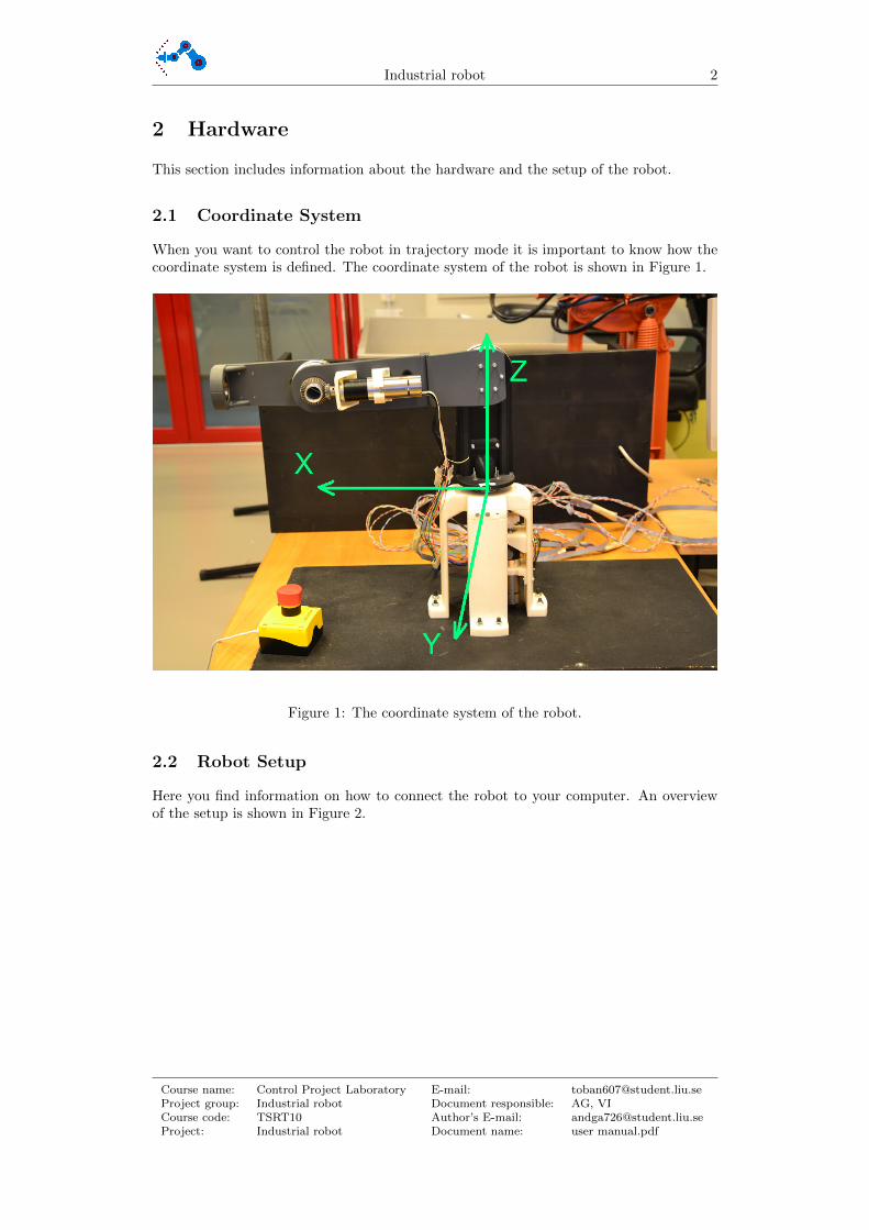
2.1 Coordinate System
When you want to control the robot in trajectory mode it is important to know how thecoordinate system is defined. The coordinate system of the robot is shown in Figure 1.
Figure 1: The coordinate system of the robot.
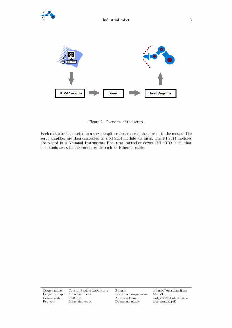
2.2 Robot Setup
Here you find information on how to connect the robot to your computer. An overviewof the setup is shown in Figure 2.
Course name: Control Project Laboratory E-mail: [email protected] group: Industrial robot Document responsible: AG, VICourse code: TSRT10 Author’s E-mail: [email protected]: Industrial robot Document name: user manual.pdf
Industrial robot 3
Figure 2: Overview of the setup.
Each motor are connected to a servo amplifier that controls the current to the motor. Theservo amplifier are then connected to a NI 9514 module via fuses. The NI 9514 modulesare placed in a National Instruments Real time controller device (NI cRIO 9022) thatcommunicates with the computer through an Ethernet cable.
Course name: Control Project Laboratory E-mail: [email protected] group: Industrial robot Document responsible: AG, VICourse code: TSRT10 Author’s E-mail: [email protected]: Industrial robot Document name: user manual.pdf

Industrial robot 4
3 Simulation
The simulation model consists of nine Matlab files and one Simulink file. Out of these filesthe ones you are interested in using is called robomatic.mdl and robotTrajectory.m. You willneed to have all the Matlab and Simulink files in the same folder on your computer. Afteryou open Matlab you have to make sure your working folder is the folder that contains allyour files. To do this press the browse button at the top of the Matlab window next tothe address field that shows you what the current folder is right now, see Figure 3. Afterthat simply find the folder that contains the files and press OK.
Figure 3: Browsing in Matlab.
The next step is to open the simulation model, to do this you can simply double click onthe file named robomatic.mdl under current folder to the left in your screen.
3.1 User interface
When you open robomatic.mdl you will see the top level of the simulation interface, seeFigure 4. The components that are of interest to you are marked with red.
Figure 4: The simulation user interface.
Course name: Control Project Laboratory E-mail: [email protected] group: Industrial robot Document responsible: AG, VICourse code: TSRT10 Author’s E-mail: [email protected]: Industrial robot Document name: user manual.pdf
Industrial robot 5
The first thing you have to do after you have opened the simulation model is to initiate allthe robot parameters. To do this just double click on the button labeled ”INIT”. Afterthat you have to choose if you want to simulate the joint target or a trajectory. A doubleclick on the switch will change between the modes.
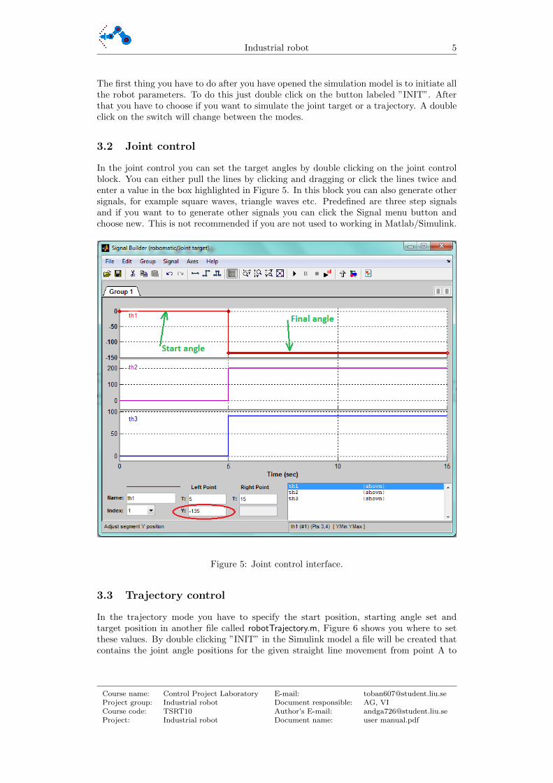
3.2 Joint control
In the joint control you can set the target angles by double clicking on the joint controlblock. You can either pull the lines by clicking and dragging or click the lines twice andenter a value in the box highlighted in Figure 5. In this block you can also generate othersignals, for example square waves, triangle waves etc. Predefined are three step signalsand if you want to to generate other signals you can click the Signal menu button andchoose new. This is not recommended if you are not used to working in Matlab/Simulink.
Figure 5: Joint control interface.
3.3 Trajectory control
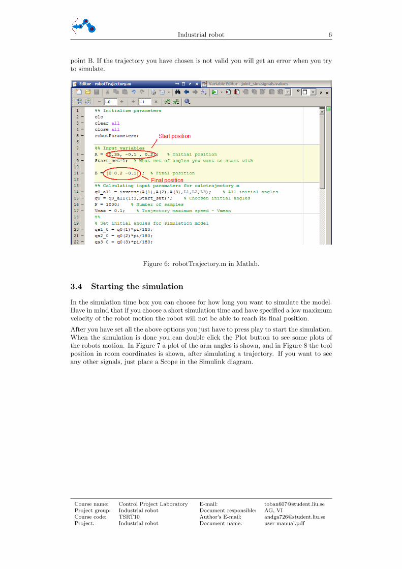
In the trajectory mode you have to specify the start position, starting angle set andtarget position in another file called robotTrajectory.m, Figure 6 shows you where to setthese values. By double clicking ”INIT” in the Simulink model a file will be created thatcontains the joint angle positions for the given straight line movement from point A to
Course name: Control Project Laboratory E-mail: [email protected] group: Industrial robot Document responsible: AG, VICourse code: TSRT10 Author’s E-mail: [email protected]: Industrial robot Document name: user manual.pdf
Industrial robot 6
point B. If the trajectory you have chosen is not valid you will get an error when you tryto simulate.
Figure 6: robotTrajectory.m in Matlab.
3.4 Starting the simulation
In the simulation time box you can choose for how long you want to simulate the model.Have in mind that if you choose a short simulation time and have specified a low maximumvelocity of the robot motion the robot will not be able to reach its final position.
After you have set all the above options you just have to press play to start the simulation.When the simulation is done you can double click the Plot button to see some plots ofthe robots motion. In Figure 7 a plot of the arm angles is shown, and in Figure 8 the toolposition in room coordinates is shown, after simulating a trajectory. If you want to seeany other signals, just place a Scope in the Simulink diagram.
Course name: Control Project Laboratory E-mail: [email protected] group: Industrial robot Document responsible: AG, VICourse code: TSRT10 Author’s E-mail: [email protected]: Industrial robot Document name: user manual.pdf

Industrial robot 7
Figure 7: Example of a position plot.
Figure 8: Example of a angle plot.
Course name: Control Project Laboratory E-mail: [email protected] group: Industrial robot Document responsible: AG, VICourse code: TSRT10 Author’s E-mail: [email protected]: Industrial robot Document name: user manual.pdf
Industrial robot 8
4 Controller program
To start the LabView project, find and open the file called RoboMatic.lvproj. The file willautomatically open with LabView. The next thing you need to do is to define the defaultposition of the robot i.e the position where all the joint angles are zero.
4.1 Defining the default position
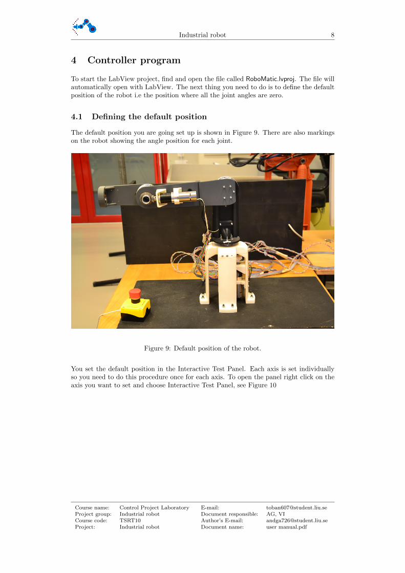
The default position you are going set up is shown in Figure 9. There are also markingson the robot showing the angle position for each joint.
Figure 9: Default position of the robot.
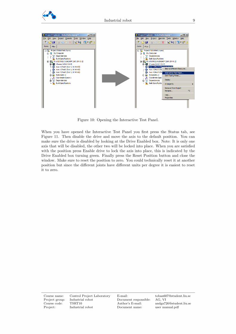
You set the default position in the Interactive Test Panel. Each axis is set individuallyso you need to do this procedure once for each axis. To open the panel right click on theaxis you want to set and choose Interactive Test Panel, see Figure 10
Course name: Control Project Laboratory E-mail: [email protected] group: Industrial robot Document responsible: AG, VICourse code: TSRT10 Author’s E-mail: [email protected]: Industrial robot Document name: user manual.pdf
Industrial robot 9
Figure 10: Opening the Interactive Test Panel.
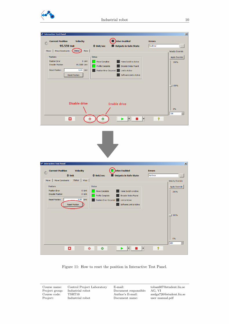
When you have opened the Interactive Test Panel you first press the Status tab, seeFigure 11. Then disable the drive and move the axis to the default position. You canmake sure the drive is disabled by looking at the Drive Enabled box. Note: It is only oneaxis that will be disabled, the other two will be locked into place. When you are satisfiedwith the position press Enable drive to lock the axis into place, this is indicated by theDrive Enabled box turning green. Finally press the Reset Position button and close thewindow. Make sure to reset the position to zero. You could technically reset it at anotherposition but since the different joints have different units per degree it is easiest to resetit to zero.
Course name: Control Project Laboratory E-mail: [email protected] group: Industrial robot Document responsible: AG, VICourse code: TSRT10 Author’s E-mail: [email protected]: Industrial robot Document name: user manual.pdf
Industrial robot 10
Figure 11: How to reset the position in Interactive Test Panel.
Course name: Control Project Laboratory E-mail: [email protected] group: Industrial robot Document responsible: AG, VICourse code: TSRT10 Author’s E-mail: [email protected]: Industrial robot Document name: user manual.pdf

Industrial robot 11
4.2 User interface
To open the user interface double click on Robomatic.vi in the Project Explorer. InFigure 12 you can see that each axis has a graph and an indicator showing its angle andangular velocity. There is also an indicator showing the current tool position. Besidesthis there are controls for the manual and automatic mode. Note that saturations on thejoint angles are implemented, so that the robot does not collide with itself.
Figure 12: The user interface in LabView.
4.3 Manual mode
In the manual mode you can control each axis separately. Set the desired angle (1) inFigure 12 and press enter, the robot will then move the axis with reduced speed. Thismode is mostly to confirm that the axis can move properly.
4.4 Automatic mode
In automatic mode you can choose to control the tool position or control the joint anglesby switching the trajectory mode on and off.
Course name: Control Project Laboratory E-mail: [email protected] group: Industrial robot Document responsible: AG, VICourse code: TSRT10 Author’s E-mail: [email protected]: Industrial robot Document name: user manual.pdf
Industrial robot 12
4.4.1 Trajectory OFF
If you wish to control the target joint angles you can select the trajectory off mode. Setthe desired target angles (1) and the angular velocity (3) in Figure 12, then press theexecute button (2) in Figure 12.
4.4.2 Trajectory ON
If you wish to control the tool in a straight line from one point to another you can setthe trajectory to ON. Note that you have to enter all the information under Trajectorycontrol, (4) in Figure 12, before you start the program. Enter the desired start positionand target position. For each position reachable for the robot there are theoretically 4ways to set the angles for that position. In the Start set box you can choose what set ofangles you want to start with. In the vmax traj you can choose the desired maximumvelocity.
When you have set all the options you can start the program. The robot will auto-matically move to the starting position with the chosen set of angles. If the robot doesnot move the trajectory is invalid. To start the trajectory simply press Execute trajectory,to reset the robot to the starting position press Execute trajectory again.
If the trajectory is invalid you can try using another set of starting angles, note thatyou have to stop the program, enter another start set and then start the program again.
4.5 Data logging
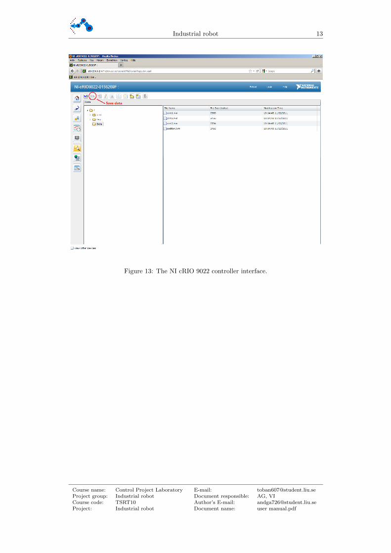
You can store data while running the robot. To start press the Data logging button and tostop just press the button again. Data regarding the joint angles and the tool position willbe saved onto the NI cRIO 9022 controller. To access this data you enter the IP-addressto the controller in the address field of your web browser. The IP-address is 169.254.0.2.The data will be located in the folder called Data, to save it onto your hard drive highlightthe file you want and click the Save data button as shown in Figure 13.
Course name: Control Project Laboratory E-mail: [email protected] group: Industrial robot Document responsible: AG, VICourse code: TSRT10 Author’s E-mail: [email protected]: Industrial robot Document name: user manual.pdf
Industrial robot 13
Figure 13: The NI cRIO 9022 controller interface.
Course name: Control Project Laboratory E-mail: [email protected] group: Industrial robot Document responsible: AG, VICourse code: TSRT10 Author’s E-mail: [email protected]: Industrial robot Document name: user manual.pdf
Industrial robot 14
5 Troubleshoot
If the robot does not move or there are any other problem try the following:
1. Check that the emergency stop button is not pressed down
2. Check if any fuses are blown and make sure the controller is connected to the powersource
3. Try restarting LabView
4. Make sure the network cable is connected and that the connection to the controlleris not broken
5. Restart the controller by cutting the power
6. As a last resort try restarting both the computer and the controller
Course name: Control Project Laboratory E-mail: [email protected] group: Industrial robot Document responsible: AG, VICourse code: TSRT10 Author’s E-mail: [email protected]: Industrial robot Document name: user manual.pdf