
USER MANUAL - Kramer AV · 2018-08-16 · 6.2 Video Output and Audio Switching Timeouts 20 6.3...
75
P/N: 2900-300523 Rev 3 www.KramerAV.com USER MANUAL MODEL: 691 HDBT 2.0 Optical Transmitter
Transcript of USER MANUAL - Kramer AV · 2018-08-16 · 6.2 Video Output and Audio Switching Timeouts 20 6.3...

P/N: 2900-300523 Rev 3 www.KramerAV.com
USER MANUAL
MODEL:
691 HDBT 2.0 Optical Transmitter

691 – Contents i
Contents
1 Introduction 1 2 Getting Started 2 2.1 Achieving the Best Performance 2 2.2 Safety Instructions 2 2.3 Recycling Kramer Products 3 3 Overview 4 4 Defining the 691 HDBT 2.0 Optical Transmitter 6 5 Connecting the 691 HDBT 2.0 Optical Transmitter 8 5.1 Using the OSP SFP+ Module 12 5.2 Connecting to 691 via RS-232 15 5.3 Connecting 691 via the Ethernet Port 16 6 Principles of Operation 20 6.1 Audio Output 20 6.2 Video Output and Audio Switching Timeouts 20 6.3 Controlling A/V Equipment via an IR Remote Control 20 7 Configuring the 691 HDBT 2.0 Optical Transmitter 23 8 Using the Embedded Web Pages 24 8.1 Browsing the 691 Web Pages 24 8.2 Setting the Sleep Mode, HDCP Mode and Audio Switching Delay Time 26 8.3 Setting Device Parameters 28 8.4 Managing the EDID 32 8.5 Authentication Page 34 8.6 Viewing the About Page 35 9 Firmware Upgrade 36 10 Technical Specifications 37 10.1 Default Communication Parameters 39 10.2 Default Parameters 39 10.3 Default EDID 39 11 Protocol 3000 42 11.1 Understanding Protocol 3000 43 11.2 Kramer Protocol 3000 Syntax 45 11.3 Protocol 3000 Commands 46
ii 691 - Contents
Figures
Figure 1: 691 Front Panel 6 Figure 2: 691 Rear Panel 7 Figure 3: Connecting the Fiber Optic Cable 9 Figure 4: Connecting the 691 and 692 11 Figure 5: System Layout Example for Optical Reach Evaluation 13 Figure 6: Inserting the Transceiver Module 14 Figure 7: RS-232 Connection 15 Figure 8: Local Area Connection Properties Window 17 Figure 9: Internet Protocol Version 4 Properties Window 18 Figure 10: Internet Protocol Version 6 Properties Window 18 Figure 11: Internet Protocol Properties Window 19 Figure 12: Controlling a Blu-ray Disk Player via the 692 Receiver 22 Figure 13: Controlling a Projector via the 691 Transmitter 22 Figure 14: 691 DIP-Switch 23 Figure 15: Entering Logon Credentials 25 Figure 16: Video & Audio Settings Page 26 Figure 17: The Device Settings Page 29 Figure 18: Turning DHCP Off Dialog Box 29 Figure 19: Turning DHCP On Warning 30 Figure 20: The EDID Management Page 33 Figure 21: The EDID Message 33 Figure 22: The Authentication Page 34 Figure 23: The About Page 35

691 - Introduction 1
1 Introduction
Welcome to Kramer Electronics! Since 1981, Kramer Electronics has been
providing a world of unique, creative, and affordable solutions to the vast range of
problems that confront video, audio, presentation, and broadcasting professionals
on a daily basis. In recent years, we have redesigned and upgraded most of our
line, making the best even better!
Our 1,000-plus different models now appear in 14 groups that are clearly defined
by function: GROUP 1: Distribution Amplifiers; GROUP 2: Switchers and Routers;
GROUP 3: Control Systems; GROUP 4: Format/Standards Converters; GROUP
5: Range Extenders and Repeaters; GROUP 6: Specialty AV Products; GROUP
7: Scan Converters and Scalers; GROUP 8: Cables and Connectors; GROUP 9:
Room Connectivity; GROUP 10: Accessories and Rack Adapters; GROUP 11:
Sierra Video Products; GROUP 12: Digital Signage; GROUP 13: Audio; and
GROUP 14: Collaboration.
Congratulations on purchasing your Kramer 691 HDBT 2.0 Optical Transmitter
which is part of the Kramer Video and Audio Distribution System and is ideal for:
• Ultra-long signals extension for:
Multi-room and inter-building ultra-long connectivity.
Large dividable auditoriums and lecture halls.
• Highly secured and reliable signals ultra-long extension for:
Governmental applications.
Medical applications.
Rental and staging applications.
691 HDBT 2.0 Optical Transmitter and 692 HDBT 2.0 Optical
Receiver are standard compliant and can be connected to other
HDBT-certified transmitters and receivers.

2 691 - Getting Started
2 Getting Started
We recommend that you:
• Unpack the equipment carefully and save the original box and packaging
materials for possible future shipment.
• Review the contents of this user manual.
Go to www.kramerav.com/downloads/691 to check for up-to-date user
manuals, application programs, and to check if firmware upgrades are
available (where appropriate).
2.1 Achieving the Best Performance
To achieve the best performance:
• Use only good quality connection cables (we recommend Kramer high-
performance, high-resolution cables) to avoid interference, deterioration in
signal quality due to poor matching, and elevated noise levels (often
associated with low quality cables).
• Do not secure the cables in tight bundles or roll the slack into tight coils.
• Avoid interference from neighboring electrical appliances that may adversely
influence signal quality.
• Position your 691 HDBT 2.0 Optical Transmitter away from moisture,
excessive sunlight and dust.
This equipment is to be used only inside a building. It may only be
connected to other equipment that is installed inside a building.
2.2 Safety Instructions
Caution: There are no operator serviceable parts inside the unit.
Warning: Use only the power cord that is supplied with the unit.
Warning: Disconnect the power and unplug the unit from the wall
before installing.

691 - Getting Started 3
2.3 Recycling Kramer Products
The Waste Electrical and Electronic Equipment (WEEE) Directive 2002/96/EC
aims to reduce the amount of WEEE sent for disposal to landfill or incineration by
requiring it to be collected and recycled. To comply with the WEEE Directive,
Kramer Electronics has made arrangements with the European Advanced
Recycling Network (EARN) and will cover any costs of treatment, recycling and
recovery of waste Kramer Electronics branded equipment on arrival at the EARN
facility. For details of Kramer’s recycling arrangements in your particular country
go to our recycling pages at www.kramerav.com/support/recycling/.
4 691 - Overview
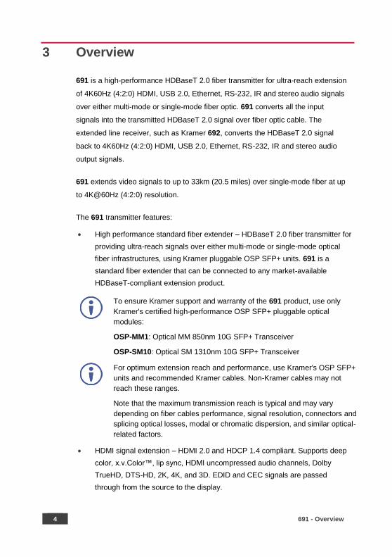
3 Overview
691 is a high-performance HDBaseT 2.0 fiber transmitter for ultra-reach extension
of 4K60Hz (4:2:0) HDMI, USB 2.0, Ethernet, RS-232, IR and stereo audio signals
over either multi-mode or single-mode fiber optic. 691 converts all the input
signals into the transmitted HDBaseT 2.0 signal over fiber optic cable. The
extended line receiver, such as Kramer 692, converts the HDBaseT 2.0 signal
back to 4K60Hz (4:2:0) HDMI, USB 2.0, Ethernet, RS-232, IR and stereo audio
output signals.
691 extends video signals to up to 33km (20.5 miles) over single-mode fiber at up
to 4K@60Hz (4:2:0) resolution.
The 691 transmitter features:
• High performance standard fiber extender – HDBaseT 2.0 fiber transmitter for
providing ultra-reach signals over either multi-mode or single-mode optical
fiber infrastructures, using Kramer pluggable OSP SFP+ units. 691 is a
standard fiber extender that can be connected to any market-available
HDBaseT-compliant extension product.
To ensure Kramer support and warranty of the 691 product, use only
Kramer's certified high-performance OSP SFP+ pluggable optical
modules:
OSP-MM1: Optical MM 850nm 10G SFP+ Transceiver
OSP-SM10: Optical SM 1310nm 10G SFP+ Transceiver
For optimum extension reach and performance, use Kramer's OSP SFP+
units and recommended Kramer cables. Non-Kramer cables may not
reach these ranges.
Note that the maximum transmission reach is typical and may vary
depending on fiber cables performance, signal resolution, connectors and
splicing optical losses, modal or chromatic dispersion, and similar optical-
related factors.
• HDMI signal extension – HDMI 2.0 and HDCP 1.4 compliant. Supports deep
color, x.v.Color™, lip sync, HDMI uncompressed audio channels, Dolby
TrueHD, DTS-HD, 2K, 4K, and 3D. EDID and CEC signals are passed
through from the source to the display.
691 - Overview 5
• I-EDIDPro™ Kramer Intelligent EDID Processing™ – Intelligent EDID
handling, processing and pass-through algorithm that ensures Plug-and-Play
operation for HDMI source and display systems.
• USB extension – USB 2.0 interface data flows in both directions, allowing
extension of HID (Human Interface Devices) peripheral devices, such as a
mouse or a keyboard. High-bandwidth USB peripheral devices, such as USB
isochronous streaming cameras and audio devices, transfer data continuously
and periodically. Delivery of their transferred data is not guaranteed by the
USB standard and is subject to both USB and HDBaseT line bandwidth
management limitations. When such devices are connected, check their
functionality to ensure bandwidth limitations are not exceeded.
• Ethernet extension – Ethernet interface data flows in both directions allowing
extension of up to 100Mbps Ethernet connectivity for LAN communication and
device control.
• Bidirectional RS-232 extension – Serial interface data flows in both directions
allowing data transmission and device control.
• Bidirectional infrared extension – IR interface data flows in both directions
allowing remote control of peripheral devices located at either end of the
extended line.
• Audio embedding (Adding) – A selectable analog unbalanced stereo audio
input is converted into a digital signal and added (embedded) to the
transmitted HDMI signal, replacing the embedded HDMI audio input signal.
This enables embedding a selectable audio source over HDMI. For example,
a presenter can display a video clip and temporarily override the audio of the
source media with another audio source, such as from a microphone.
• Cost-effective maintenance – Status LED indicators for the HDMI input and
HDBT output link facilitate easy local troubleshooting. Remote device
management via built-in web UI and RS-232 connection enable simple
device maintenance. Kramer Network support provides remote device and
network management. Local and remote firmware upgrade via mini-USB,
RS-232 or Ethernet connection and the K-Upload tool ensure lasting,
field-proven deployment.
• Easy installation – Half 19” 1U rack mountable fan-less enclosure enables
side-by-side mounting of 2 units in a 1U rack space.

6 691 - Defining the 691 HDBT 2.0 Optical Transmitter
4 Defining the 691 HDBT 2.0 Optical Transmitter
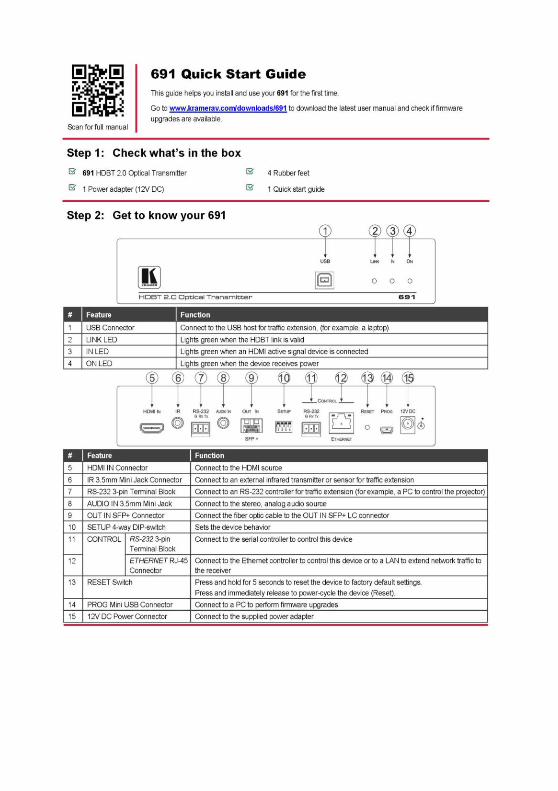
Figure 1 defines the front panel of the 691.
Figure 1: 691 Front Panel
# Feature Function
1 USB Connector Connect to the USB host for traffic extension (for example, a laptop).
2 LINK LED Lights green when the HDBT link is valid.
3 IN LED Lights green when an HDMI active signal device is connected.
4 ON LED Lights green when the device receives power.
691 - Defining the 691 HDBT 2.0 Optical Transmitter 7
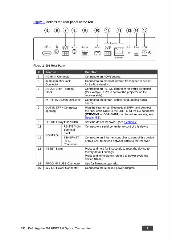
Figure 2 defines the rear panel of the 691.
Figure 2: 691 Rear Panel
# Feature Function
5 HDMI IN Connector Connect to an HDMI source.
6 IR 3.5mm Mini Jack Connector
Connect to an external infrared transmitter or sensor for traffic extension.
7 RS-232 3-pin Terminal Block
Connect to an RS-232 controller for traffic extension (for example, a PC to control the projector on the receiver side).
8 AUDIO IN 3.5mm Mini Jack Connect to the stereo, unbalanced, analog audio source.
9 OUT IN SFP+ Connector opening
Plug the Kramer certified optical SFP+, and connect the fiber optic cable to the OUT IN SFP+ LC connector (OSP-MM1 or OSP-SM10, purchased separately, see Section 5.1).
10 SETUP 4-way DIP-switch Sets the device behavior, (see Section 7).
11
CONTROL
RS-232 3-pin Terminal Block
Connect to a serial controller to control this device.
12 ETHERNET RJ-45 Connector
Connect to an Ethernet controller to control this device or to a LAN to extend network traffic to the receiver.
13 RESET Switch Press and hold for 5 seconds to reset the device to factory default settings.
Press and immediately release to power-cycle the device (Reset).
14 PROG Mini USB Connector Use for firmware upgrade.
15 12V DC Power Connector Connect to the supplied power adapter.
8 691 - Connecting the 691 HDBT 2.0 Optical Transmitter
5 Connecting the 691 HDBT 2.0 Optical Transmitter
Always switch off the power to each device before connecting it to
your 691. After connecting your 691, connect the power to and switch
on each device.
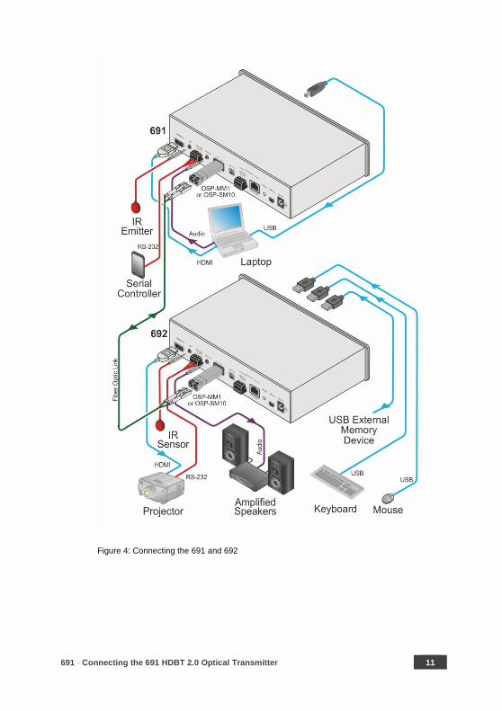
You can use the 691 HDBT 2.0 Optical Transmitter and a compatible receiver, for
example, the Kramer 692 HDBT 2.0 Optical Receiver to configure a paired HDMI
transmitter/receiver system, as shown in the example in Figure 4.
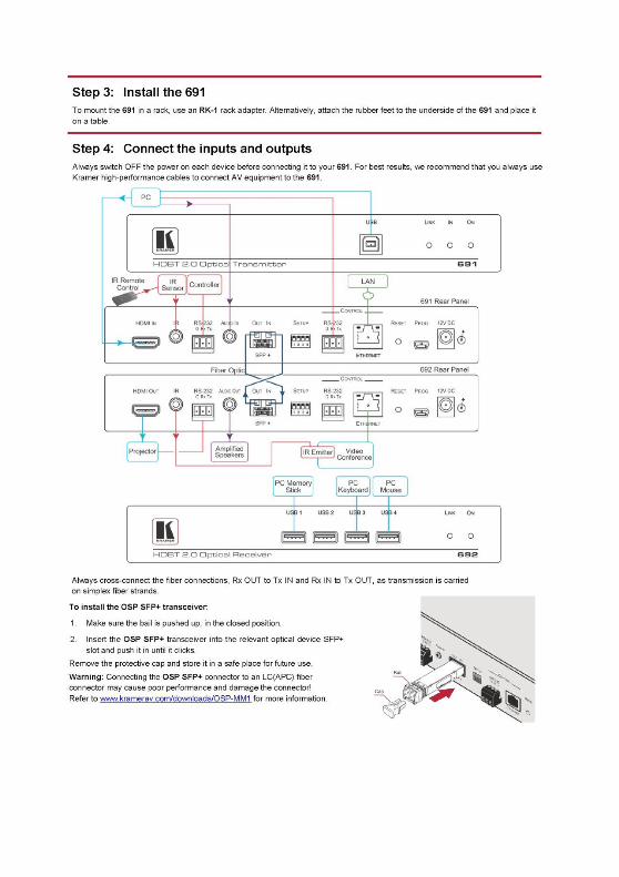
To connect the 691 HDBT 2.0 Optical Transmitter:
On the 691 transmitter:
1. Connect an HDMI source, (for example, a laptop) to the HDMI IN connector.
2. Connect an RS-232 serial controller to the RS-232 3-pin terminal block for
traffic extension, to control the projector (on the receiver side).
3. Connect a stereo analog audio source (for example, the audio output of a
PC) to the AUDIO IN 3.5mm mini jack for traffic extension.
4. Connect the USB port on a PC to the USB port on the front panel of the 691
for traffic extension.
5. Connect an external IR emitter to the IR 3.5mm mini jack for traffic
extension.
6. Insert the OSP-MM1/OSP-SM10 transceiver module into the OUT/IN SFP+
opening, see Section 5.1.
691 - Connecting the 691 HDBT 2.0 Optical Transmitter 9
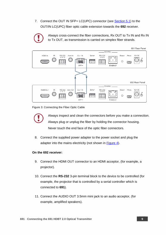
7. Connect the OUT IN SFP+ LC(UPC) connector (see Section 5.1) to the
OUT/IN LC(UPC) fiber optic cable extension towards the 692 receiver.
Always cross-connect the fiber connections, Rx OUT to Tx IN and Rx IN
to Tx OUT, as transmission is carried on simplex fiber strands.
Figure 3: Connecting the Fiber Optic Cable
Always inspect and clean the connectors before you make a connection.
Always plug or unplug the fiber by holding the connector housing.
Never touch the end face of the optic fiber connectors.
8. Connect the supplied power adapter to the power socket and plug the
adapter into the mains electricity (not shown in Figure 4).
On the 692 receiver:
9. Connect the HDMI OUT connector to an HDMI acceptor, (for example, a
projector).
10. Connect the RS-232 3-pin terminal block to the device to be controlled (for
example, the projector that is controlled by a serial controller which is
connected to 691).
11. Connect the AUDIO OUT 3.5mm mini jack to an audio acceptor, (for
example, amplified speakers).

10 691 - Connecting the 691 HDBT 2.0 Optical Transmitter
12. Connect the USB ports (for example, USB keyboard and mouse and a USB
external memory device).
13. Connect the IR 3.5mm mini jack to an IR sensor.
14. Insert the recommended OSP SFP+ modules (make sure the bail is closed
and in the upward position) into the IN OUT SFP+ slot and push it in until it
clicks, see Section 5.1.
15. Remove the protective cap and keep for future use.
16. Connect the OUT IN SFP+ LC(UPC) connector to the IN/OUT LC(UPC)
connector of the fiber optic cable extension towards the 691 transmitter.
Always cross-connect the fiber connections, Rx OUT to Tx IN and Rx IN
to Tx OUT, as transmission is carried on simplex fiber strands (see
Figure 3).
Always inspect and clean the connectors before you make a connection.
Always plug or unplug the fiber by holding the connector housing.
Never touch the end face of the fiber connectors.
17. Connect the supplied power adapter to the power socket and plug the
adapter into the mains electricity (not shown in Figure 4).
691 - Connecting the 691 HDBT 2.0 Optical Transmitter 11
Figure 4: Connecting the 691 and 692

12 691 - Connecting the 691 HDBT 2.0 Optical Transmitter
5.1 Using the OSP SFP+ Module
Before connecting the 691 to an optical receiver, you need to insert the same type
of SFP+ transceiver both into the SFP+ opening on the 691 and the compatible
receiver.
Two types of Kramer SFP+ optical transceiver modules are available:
• OSP-MM1: Optical MM 850nm 10G SFP+ Transceiver
• OSP-SM10: Optical SM 1310nm 10G SFP+ Transceiver
Before deciding which transceiver module to use, consider the infra-structure of
the installation area, the desired distance, optical loss budget and typical expected
loss.
Use the same type of SFP+ optical transceiver module both on the 691
transmitter and the receiver (for example 692).
The following table defines various typical Fiber cable characteristics, used for
optical reach evaluation:
Cable Category Core Diameter [µm]
Wavelength Fiber Loss [dB/km]
Connector Loss [dB]
Splice Loss [dB]
MM OM1 [G.651.1] 62.5/125 850nm 3 Typical: 0.3
Max.: 0.75
0.3
MM OM2 [G.651.1] 50/125
MM OM3 [G.651.1, Laser Optimized]
2.5
MM OM4 [G.651.1, Laser Optimized]
MM OM5
SM OS1 [G.652A/B] 8 1310nm 1
SM OS2 [G.652C/D] 0.4
OSP-MM1 and OSP-SM10 modules are designed to be used only with
LC(UPC) blue or LC(PC) white connectors. Using an LC(APC) green
connector with the module causes poor performance and can damage
the module connector.
For all other cable connections that do not connect directly to the
OSP-MM1 or OSP-SM10 modules, such as the optical patch panel and
bulk cables illustrated in Figure 5, we recommend using Angled Physical
Contact (APC) green connectors for improved end-to-end reach
performance.
691 - Connecting the 691 HDBT 2.0 Optical Transmitter 13
When using OSP modules consider the following:
• Modules are Class 1 Laser products.
• There may be Invisible laser radiation present.
• Avoid long-term viewing of laser.
• Avoid the use of magnifying viewing aids or instruments (such as
binoculars, telescopes, microscopes and magnifying lenses, but not
spectacles or contact lenses).
• Avoid placing optical devices in the emitted beam that could cause
the concentration of the laser radiation to be increased.
5.1.1 Optical Reach Evaluation
The following examples show how to calculate dB loss during optical signal
transmission over fiber optical infrastructure.
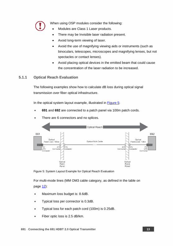
In the optical system layout example, illustrated in Figure 5:
• 691 and 692 are connected to a patch panel via 100m patch cords.
• There are 6 connectors and no splices.
Figure 5: System Layout Example for Optical Reach Evaluation
For multi-mode lines (MM OM3 cable category, as defined in the table on
page 12):
• Maximum loss budget is: 8.6dB.
• Typical loss per connector is 0.3dB.
• Typical loss for each patch cord (100m) is 0.25dB.
• Fiber optic loss is 2.5 dB/km.

14 691 - Connecting the 691 HDBT 2.0 Optical Transmitter
Multi-mode bulk line budget is: 8.6 – (0.3x6 +0.25x2) = 6.3dB.
Evaluated bulk line length is: 6.3/2.5=~2.5km.
For single-mode lines (SM OS1 cable category, as defined in the table on
page 12):
• Maximum loss budget is: 11.9dB.
• Typical loss per connector is 0.3dB.
• Typical loss for each patch cord (100m) is 0.1dB.
• Fiber optic loss is 1 dB/km.
Single-mode bulk line loss budget is: 11.9 – (0.3x6 +0.1x2) = 9.9dB.
Evaluated bulk line length is: 9.9/1=~9.9km.
5.1.2 Inserting the SFP+ Module
To insert the SFP+ module:
1. Make sure the bail is pushed up, in the closed position.
2. Insert the OSP-MM1/OSP-SM10 into the IN OUT SFP+ slot and push it in
until it clicks.
Figure 6: Inserting the Transceiver Module
691 - Connecting the 691 HDBT 2.0 Optical Transmitter 15
3. Remove the protective cap and keep for future use.
For more information, see the OSP-MM1/OSP-SM10 documentation
available at www.kramerav.com/product/osp-mm1.
5.2 Connecting to 691 via RS-232
The 691 features two RS-232 3-pin terminal block connectors:
• RS-232 to pass data to and from the machines that are connected to the
receiver.
• RS-232 CONTROL to control the 691.
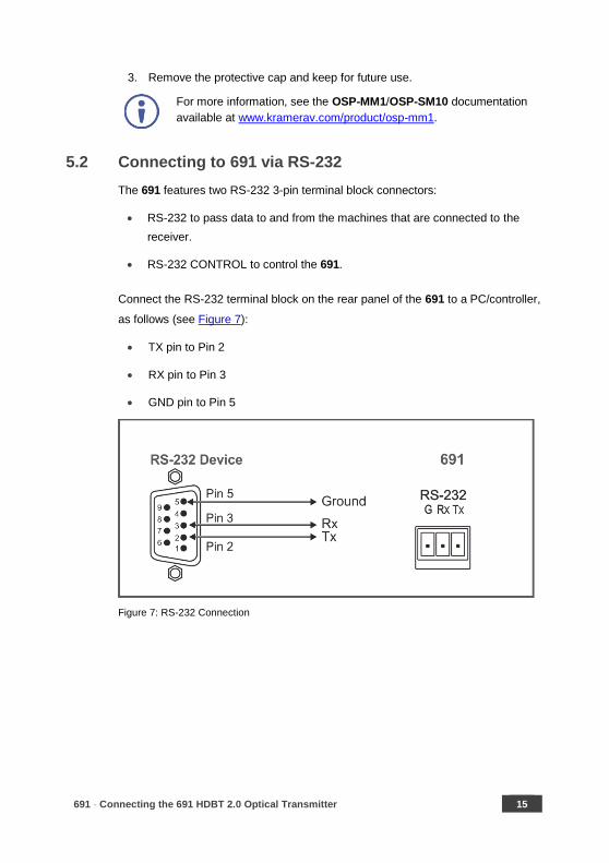
Connect the RS-232 terminal block on the rear panel of the 691 to a PC/controller,
as follows (see Figure 7):
• TX pin to Pin 2
• RX pin to Pin 3
• GND pin to Pin 5
Figure 7: RS-232 Connection
16 691 - Connecting the 691 HDBT 2.0 Optical Transmitter
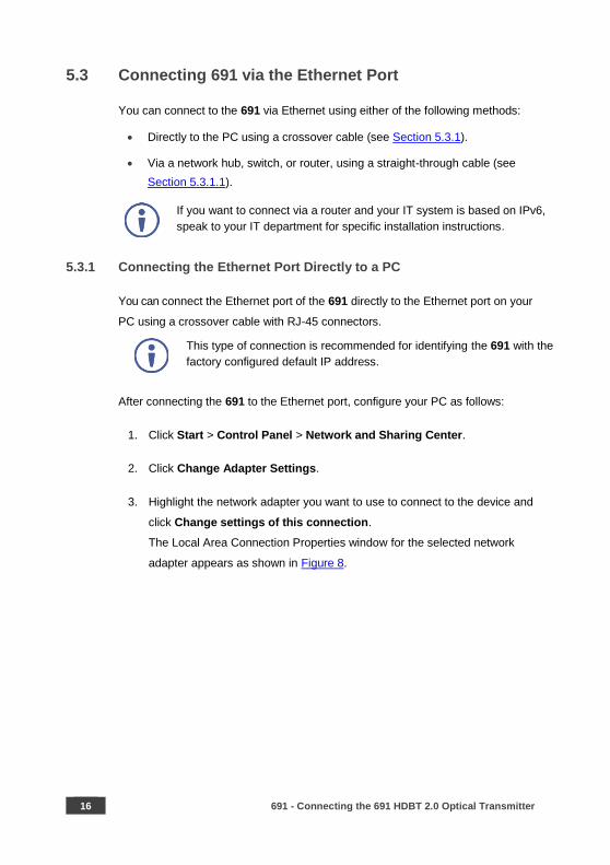
5.3 Connecting 691 via the Ethernet Port
You can connect to the 691 via Ethernet using either of the following methods:
• Directly to the PC using a crossover cable (see Section 5.3.1).
• Via a network hub, switch, or router, using a straight-through cable (see
Section 5.3.1.1).
If you want to connect via a router and your IT system is based on IPv6,
speak to your IT department for specific installation instructions.
5.3.1 Connecting the Ethernet Port Directly to a PC
You can connect the Ethernet port of the 691 directly to the Ethernet port on your
PC using a crossover cable with RJ-45 connectors.
This type of connection is recommended for identifying the 691 with the
factory configured default IP address.
After connecting the 691 to the Ethernet port, configure your PC as follows:
1. Click Start > Control Panel > Network and Sharing Center.
2. Click Change Adapter Settings.
3. Highlight the network adapter you want to use to connect to the device and
click Change settings of this connection.
The Local Area Connection Properties window for the selected network
adapter appears as shown in Figure 8.
691 - Connecting the 691 HDBT 2.0 Optical Transmitter 17
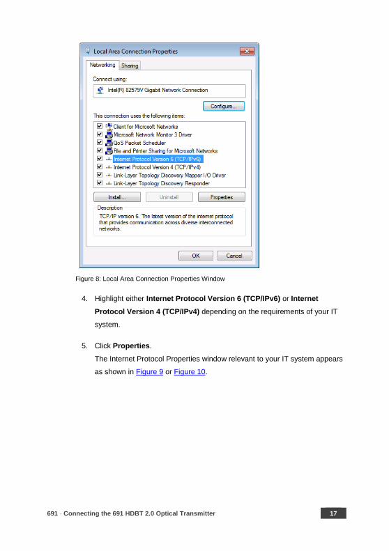
Figure 8: Local Area Connection Properties Window
4. Highlight either Internet Protocol Version 6 (TCP/IPv6) or Internet
Protocol Version 4 (TCP/IPv4) depending on the requirements of your IT
system.
5. Click Properties.
The Internet Protocol Properties window relevant to your IT system appears
as shown in Figure 9 or Figure 10.

18 691 - Connecting the 691 HDBT 2.0 Optical Transmitter
Figure 9: Internet Protocol Version 4 Properties Window
Figure 10: Internet Protocol Version 6 Properties Window
6. Select Use the following IP Address for static IP addressing and fill in the
details as shown in Figure 11.
For TCP/IPv4 you can use any IP address in the range 192.168.1.1 to
192.168.1.255 (excluding 192.168.1.39) that is provided by your IT
department.

691 - Connecting the 691 HDBT 2.0 Optical Transmitter 19
Figure 11: Internet Protocol Properties Window
7. Click OK.
8. Click Close.
5.3.1.1 Connecting the ETHERNET Port via a Network Hub or Switch
You can connect the Ethernet port of the 691 to the Ethernet port on a network
hub or network router, via a straight-through cable with RJ-45 connectors.

20 691 - Principles of Operation
6 Principles of Operation
This section describes the audio output setup conditions, the video and audio
timeouts and AV IR control.
6.1 Audio Output
The audio source that is routed to the output depends on the SETUP DIP-switch
settings (see Section 7) and also on whether there is an audio signal on the input
ports. The audio output follows the rules described in the following table.
HDMI Audio Detected
Analog Audio Detected
DIP-switch 4 DIP-switch 2 Audio Out
N/A N/A Manual (On) HDMI (Off) HDMI
N/A N/A Manual (On) Analog (On) Analog
Yes No Auto (Off) N/A HDMI
Yes Yes Auto (Off) HDMI (Off) HDMI
Yes Yes Auto (Off) Analog (On) Analog
No Yes Auto (Off) N/A Analog
No No Auto (Off) N/A No audio
6.2 Video Output and Audio Switching Timeouts
The device can automatically turn off the video signal output and audio source
switching after definable intervals following the loss of the input signals or
unplugging of the input cables. The delay can be set in one of two ways:
• Using the AV-SW-TIMEOUT Protocol 3000 command
(see Section 11.3.1.11).
• Using the 691 embedded web-pages settings (see Section 8.2)
If you are working with a receiver that supports setting a timeout
(e.g., 692), you need to set the 5V timer only on the receiver side.
6.3 Controlling A/V Equipment via an IR Remote Control
Since the IR connection between the 691 transmitter and 692 receiver is
bidirectional, you can use a remote control transmitter (that is used for controlling
a peripheral device, for example, a Blu-ray disk player) to send commands from
either end of the transmitter or receiver system. To use a remote control
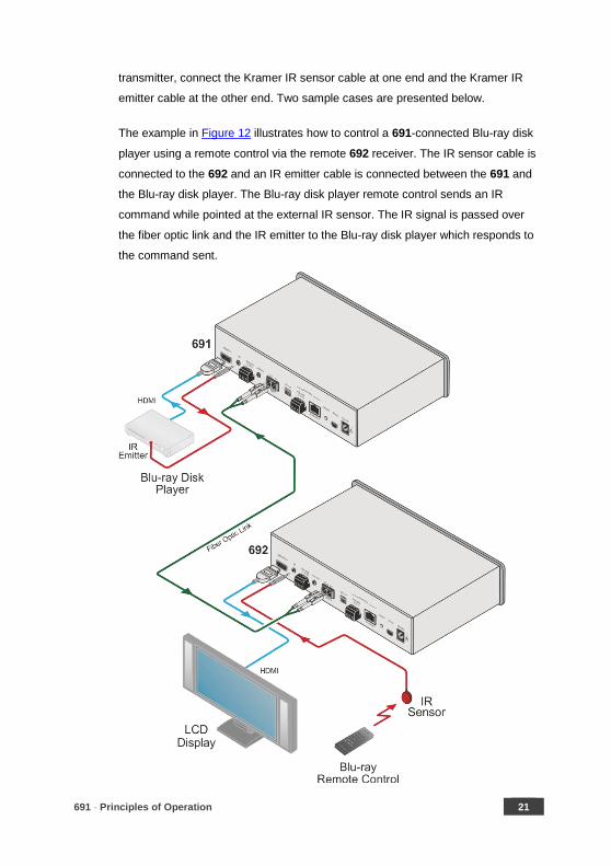
691 - Principles of Operation 21
transmitter, connect the Kramer IR sensor cable at one end and the Kramer IR
emitter cable at the other end. Two sample cases are presented below.
The example in Figure 12 illustrates how to control a 691-connected Blu-ray disk
player using a remote control via the remote 692 receiver. The IR sensor cable is
connected to the 692 and an IR emitter cable is connected between the 691 and
the Blu-ray disk player. The Blu-ray disk player remote control sends an IR
command while pointed at the external IR sensor. The IR signal is passed over
the fiber optic link and the IR emitter to the Blu-ray disk player which responds to
the command sent.
22 691 - Principles of Operation
Figure 12: Controlling a Blu-ray Disk Player via the 692 Receiver
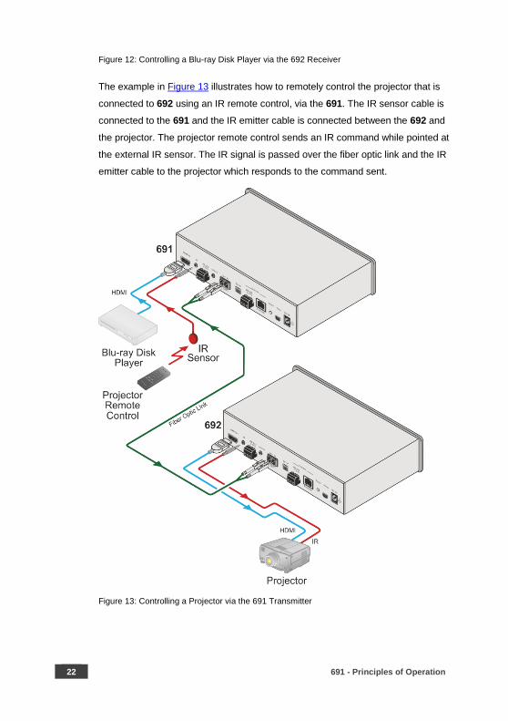
The example in Figure 13 illustrates how to remotely control the projector that is
connected to 692 using an IR remote control, via the 691. The IR sensor cable is
connected to the 691 and the IR emitter cable is connected between the 692 and
the projector. The projector remote control sends an IR command while pointed at
the external IR sensor. The IR signal is passed over the fiber optic link and the IR
emitter cable to the projector which responds to the command sent.
Figure 13: Controlling a Projector via the 691 Transmitter
691 - Configuring the 691 HDBT 2.0 Optical Transmitter 23
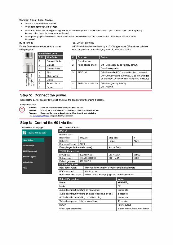
7 Configuring the 691 HDBT 2.0 Optical Transmitter
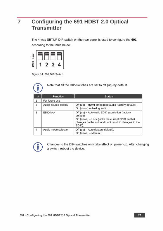
The 4-way SETUP DIP-switch on the rear panel is used to configure the 691
according to the table below.
Figure 14: 691 DIP-Switch
Note that all the DIP-switches are set to off (up) by default.
# Function Status
1 For future use
2 Audio source priority Off (up) – HDMI embedded audio (factory default).
On (down) – Analog audio.
3 EDID lock Off (up) – Automatic EDID acquisition (factory default).
On (down) – Lock (locks the current EDID so that changes on the output do not result in changes to the EDID).
4 Audio mode selection Off (up) – Auto (factory default).
On (down) – Manual.
Changes to the DIP-switches only take effect on power-up. After changing
a switch, reboot the device.

24 691 - Using the Embedded Web Pages
8 Using the Embedded Web Pages
The 691 can be managed remotely using its embedded Web pages. The Web
pages are accessed using a web browser and an Ethernet connection.
Before attempting to connect:
• Connect the 691 via the Ethernet port.
• Make sure that your browser is supported (see Section 9).
The 691 Web pages enable performing the following:
• Setting sleep mode, HDCP and audio switching delay time (see Section 8.2).
• Setting the device parameters and performing a factory reset (see Section
8.3).
• Managing the EDID (see Section 8.4).
• Authentication (see Section 8.5).
• Viewing the Web version and other Kramer details (see Section 8.6).
8.1 Browsing the 691 Web Pages
In the event that a Web page does not update correctly, clear your web
browser’s cache by pressing CTRL+F5.
Only one instance of the Web page can be open at a time.
To browse the 691 Web pages:
1. Open your Internet browser.
2. Type the IP address of the device in the address bar of your browser. For
example, the default IP address:
The Authentication window appears.
691 - Using the Embedded Web Pages 25
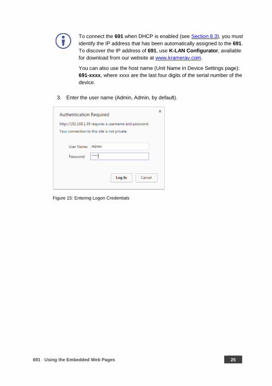
To connect the 691 when DHCP is enabled (see Section 8.3), you must
identify the IP address that has been automatically assigned to the 691.
To discover the IP address of 691, use K-LAN Configurator, available
for download from our website at www.kramerav.com.
You can also use the host name (Unit Name in Device Settings page):
691-xxxx, where xxxx are the last four digits of the serial number of the
device.
3. Enter the user name (Admin, Admin, by default).
Figure 15: Entering Logon Credentials
26 691 - Using the Embedded Web Pages
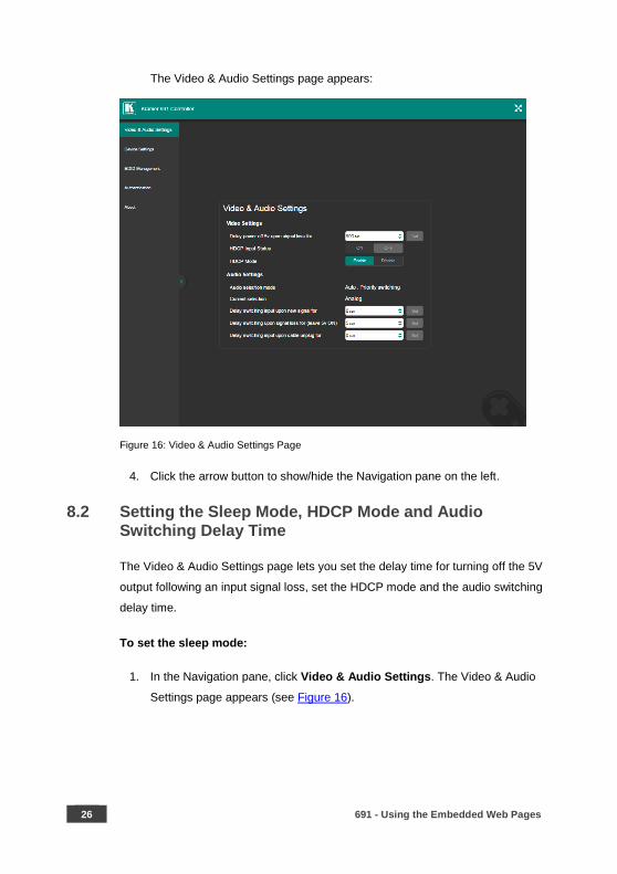
The Video & Audio Settings page appears:
Figure 16: Video & Audio Settings Page
4. Click the arrow button to show/hide the Navigation pane on the left.
8.2 Setting the Sleep Mode, HDCP Mode and Audio Switching Delay Time
The Video & Audio Settings page lets you set the delay time for turning off the 5V
output following an input signal loss, set the HDCP mode and the audio switching
delay time.
To set the sleep mode:
1. In the Navigation pane, click Video & Audio Settings. The Video & Audio
Settings page appears (see Figure 16).
691 - Using the Embedded Web Pages 27
2. Set the video delay time in seconds.
3. Click Set.
The delay time is detected by the receiver. For example, the receiver
only senses that the clock was lost and acts according to the input
signal loss timeout.
To set the HDCP mode:
1. In the Navigation pane, click Video & Audio Settings. The Video & Audio
Settings page appears (see Figure 16).
2. View the HDCP input status.
3. Enable or disable the HDCP mode.
You must set the HDCP preferences in at least the transmitter or
receiver.
To set the audio switching delay:
1. In the Navigation pane, click Video & Audio Settings. The Video & Audio
Settings page appears (see Figure 16).
2. Set the delay times for:
New signal
Signal loss
Cable unplug
3. Click Set.
Audio Priority switching is set via the DIP-switches, see Section 6.17.
28 691 - Using the Embedded Web Pages
8.3 Setting Device Parameters
The Device Settings web page lets you view some of the device characteristics,
(for example, model and firmware version) and also enables performing the
following functions:
• Setting the device name.
• Changing the Ethernet settings.
• Loading and saving configurations for duplicating multiple device definitions
for easy system configuration.
• Performing a factory reset.
To set the device name:
1. In the Navigation pane, click Device Settings. The Device Settings page
appears:
2. Type the name in the Name text box and click Set.
691 - Using the Embedded Web Pages 29
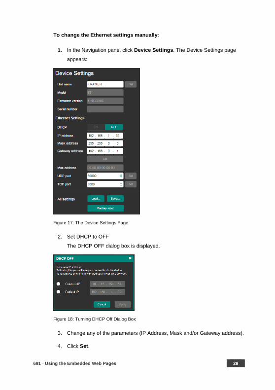
To change the Ethernet settings manually:
1. In the Navigation pane, click Device Settings. The Device Settings page
appears:
Figure 17: The Device Settings Page
2. Set DHCP to OFF
The DHCP OFF dialog box is displayed.
Figure 18: Turning DHCP Off Dialog Box
3. Change any of the parameters (IP Address, Mask and/or Gateway address).
4. Click Set.

30 691 - Using the Embedded Web Pages
To automatically set Ethernet settings:
1. In the Navigation pane, click Device Settings. The Device Settings page
appears (see Figure 17):
2. Set DHCP to ON.
3. The Communication Warning window appears.
Figure 19: Turning DHCP On Warning
4. Click OK.
DHCP is turned on. The next time 691 is booted you must reload the Web
pages using the IP address issued to the 691 by the DHCP server.
To turn DHCP off:
1. Set DHCP to OFF.
The DHCP OFF dialog box is displayed (see Figure 18).
2. To set a custom IP address, select Custom IP and enter the required
address. To set the default IP address, select Default IP.
3. Click Apply.
The 691 IP address is changed and the Web page reloads automatically.
4 . Click Set.
After changing the IP address, you need to reload the web page with the
new IP address.
After changing the Subnet mask you need to turn the 691 power off and
then on again.
691 - Using the Embedded Web Pages 31
To set the UDP/TCP ports:
1. In the Navigation pane, click Device Settings. The Device Settings page
appears (see Figure 17).
2. Set the port number.
3. Click Set.
To save the current configuration to your PC:
1. In the Navigation pane, click Device Settings. The Device Settings page
appears (see Figure 17).
2. Configure the device as required.
3. Click Save.
The Save File window opens.
4. Browse to the required location to which to save the file.
5. Click OK.
The current configuration is saved.
When using Chrome, the file is automatically saved in the Downloads
folder.
To retrieve a saved configuration from your PC:
1. Connect your PC to the device to which you want to load the configuration.
2. Open the embedded Web pages (see Section 8.1).
3. In the Navigation pane, click Device Settings. The Device Settings page
appears (see Figure 17).
4. Click Load.
The explorer window opens.
5. Browse to the required file.

32 691 - Using the Embedded Web Pages
6. Select the required file and click Open.
The device is configured according to the saved preset.
The following parameters are saved to the configuration file:
• From the Video & Audio Settings page (see Figure 16):
Video HDCP Mode.
Power off 5V upon video signal loss delay time.
Switching input upon new audio detected signal delay time.
Switching upon audio signal loss (5V remains on) delay time.
Switching input upon audio cable unplug delay time.
• From the Device Settings page (see Figure 17):
Unit Name.
UDP port settings
TCP port settings
To reset 691 to its factory default values:
1. In the Navigation pane, click Device Settings. The Device Settings page
appears (see Figure 17).
2. Click Factory reset.
The confirmation message is displayed.
3. Click OK to continue or Cancel to exit the procedure.
8.4 Managing the EDID
The EDID Management page lets you read the EDID from the:
• Output
• Default EDID
• EDID data file
The selected EDID source can then be copied to the input.
691 - Using the Embedded Web Pages 33
Do not power up the display before locking the EDID.
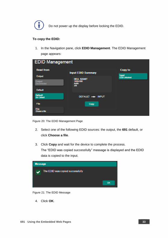
To copy the EDID:
1. In the Navigation pane, click EDID Management. The EDID Management
page appears:
Figure 20: The EDID Management Page
2. Select one of the following EDID sources: the output, the 691 default, or
click Choose a file.
3. Click Copy and wait for the device to complete the process.
The “EDID was copied successfully” message is displayed and the EDID
data is copied to the input.
Figure 21: The EDID Message
4. Click OK.
34 691 - Using the Embedded Web Pages
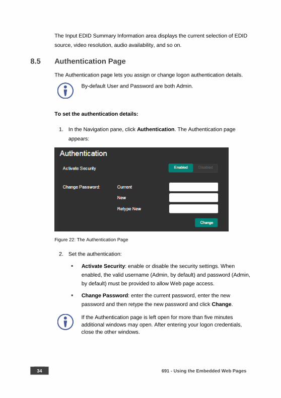
The Input EDID Summary Information area displays the current selection of EDID
source, video resolution, audio availability, and so on.
8.5 Authentication Page
The Authentication page lets you assign or change logon authentication details.
By-default User and Password are both Admin.
To set the authentication details:
1. In the Navigation pane, click Authentication. The Authentication page
appears:
Figure 22: The Authentication Page
2. Set the authentication:
Activate Security: enable or disable the security settings. When
enabled, the valid username (Admin, by default) and password (Admin,
by default) must be provided to allow Web page access.
Change Password: enter the current password, enter the new
password and then retype the new password and click Change.
If the Authentication page is left open for more than five minutes
additional windows may open. After entering your logon credentials,
close the other windows.

691 - Using the Embedded Web Pages 35
8.6 Viewing the About Page
The 691 About page lets you view the Web page version and Kramer Electronics
Ltd details.
Figure 23: The About Page

36 691 - Firmware Upgrade
9 Firmware Upgrade
You can upgrade the 691 via the Kramer K-UPLOAD tool.
The latest firmware version and the latest version of K-UPLOAD and
installation instructions can be downloaded from Kramer Web site at
www.kramerav.com/downloads/691.

691 - Technical Specifications 37
10 Technical Specifications
Inputs 1 HDMI On a female HDMI connector
1 Stereo Analog Unbalanced Audio
2Vrms / 10kΩ on a 3.5mm mini jack
Outputs 1 Fiber Optic On 2 LC connectors
Ports 1 IR On a 3.5mm mini jack for IR link extension
1 USB On a female USB-B connector for USB link extension
1 RS-232 On a 3-pin terminal block for serial link extension
1 RS-232 On a 3-pin terminal block for device control
1 100BaseT Ethernet On an RJ-45 female connector for device control and LAN extension
Extension Line Compliance HDBaseT 2.0
Optical Fiber Multi-mode (MM) or single-mode (SM)
Fiber Line 2 simplex strands
Optical Module 10Gbps SFP+ IEEE 802.3ae compliant
Multi-mode Line Compliance G.651.1 OFNR fiber
Nominal Peak Wavelength 850nm
Max Data Rate 10.2Gbps
Typical Optical Transmission Power
-2.5dBm
Typical Optical Maximum Loss Budget
8.6dB
Max Reach over OM3 MM Fiber 3km (1.86 miles)
Single-mode Line
Compliance G.652D OFNR fiber
Nominal Peak Wavelength 1310nm
Max Data Rate 10.2Gbps
Typical Optical Transmission Power
-2.5dBm
Typical Optical Maximum Loss Budget
11.9dB
Max Reach over OS1 SM Fiber 33km (20.5 miles)
Video Max Bandwidth 10.2Gbps (3.4Gbps per graphic channel)
Max Resolution 4K UHD @60Hz (4:2:0) 24bpp resolution
Compliance HDMI 2.0 and HDCP 1.4
Analog Audio Max Vrms Level 1
THD + NOISE 0.03% @1kHz at nominal level
38 691 - Technical Specifications
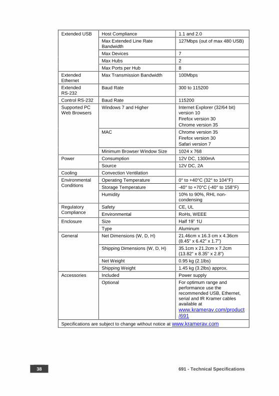
Extended USB Host Compliance 1.1 and 2.0
Max Extended Line Rate Bandwidth
127Mbps (out of max 480 USB)
Max Devices 7
Max Hubs 2
Max Ports per Hub 8
Extended Ethernet
Max Transmission Bandwidth 100Mbps
Extended RS-232
Baud Rate 300 to 115200
Control RS-232 Baud Rate 115200
Supported PC Web Browsers
Windows 7 and Higher
Internet Explorer (32/64 bit) version 10
Firefox version 30
Chrome version 35
MAC Chrome version 35
Firefox version 30
Safari version 7
Minimum Browser Window Size 1024 x 768
Power Consumption 12V DC, 1300mA
Source 12V DC, 2A
Cooling Convection Ventilation
Environmental Conditions
Operating Temperature 0° to +40°C (32° to 104°F)
Storage Temperature -40° to +70°C (-40° to 158°F)
Humidity 10% to 90%, RHL non-condensing
Regulatory Compliance
Safety CE, UL
Environmental RoHs, WEEE
Enclosure Size Half 19” 1U
Type Aluminum
General Net Dimensions (W, D, H) 21.46cm x 16.3 cm x 4.36cm (8.45" x 6.42" x 1.7")
Shipping Dimensions (W, D, H) 35.1cm x 21.2cm x 7.2cm (13.82" x 8.35" x 2.8")
Net Weight 0.95 kg (2.1lbs)
Shipping Weight 1.45 kg (3.2lbs) approx.
Accessories Included Power supply
Optional For optimum range and performance use the recommended USB, Ethernet, serial and IR Kramer cables available at
www.kramerav.com/product/691
Specifications are subject to change without notice at www.kramerav.com
691 - Technical Specifications 39
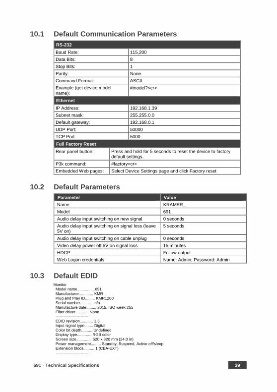
10.1 Default Communication Parameters
RS-232
Baud Rate: 115,200
Data Bits: 8
Stop Bits: 1
Parity: None
Command Format: ASCII
Example (get device model name):
#model?<cr>
Ethernet
IP Address: 192.168.1.39
Subnet mask: 255.255.0.0
Default gateway: 192.168.0.1
UDP Port: 50000
TCP Port: 5000
Full Factory Reset
Rear panel button: Press and hold for 5 seconds to reset the device to factory default settings.
P3k command: #factory<cr>
Embedded Web pages: Select Device Settings page and click Factory reset
10.2 Default Parameters
Parameter Value
Name KRAMER_
Model 691
Audio delay input switching on new signal 0 seconds
Audio delay input switching on signal loss (leave 5V on)
5 seconds
Audio delay input switching on cable unplug 0 seconds
Video delay power off 5V on signal loss 15 minutes
HDCP Follow output
Web Logon credentials Name: Admin; Password: Admin
10.3 Default EDID Monitor Model name............... 691 Manufacturer............. KMR Plug and Play ID......... KMR1200 Serial number............ n/a Manufacture date......... 2015, ISO week 255 Filter driver............ None ------------------------- EDID revision............ 1.3 Input signal type........ Digital Color bit depth.......... Undefined Display type............. RGB color Screen size.............. 520 x 320 mm (24.0 in) Power management......... Standby, Suspend, Active off/sleep Extension blocs.......... 1 (CEA-EXT) -------------------------

40 691 - Technical Specifications
DDC/CI................... n/a Color characteristics Default color space...... Non-sRGB Display gamma............ 2.20 Red chromaticity......... Rx 0.674 - Ry 0.319 Green chromaticity....... Gx 0.188 - Gy 0.706 Blue chromaticity........ Bx 0.148 - By 0.064 White point (default).... Wx 0.313 - Wy 0.329 Additional descriptors... None Timing characteristics Horizontal scan range.... 30-83kHz Vertical scan range...... 56-76Hz Video bandwidth.......... 170MHz CVT standard............. Not supported GTF standard............. Not supported Additional descriptors... None Preferred timing......... Yes Native/preferred timing.. 1280x720p at 60Hz (16:10) Modeline............... "1280x720" 74.250 1280 1390 1430 1650 720 725 730 750 +hsync +vsync Standard timings supported 720 x 400p at 70Hz - IBM VGA 720 x 400p at 88Hz - IBM XGA2 640 x 480p at 60Hz - IBM VGA 640 x 480p at 67Hz - Apple Mac II 640 x 480p at 72Hz - VESA 640 x 480p at 75Hz - VESA 800 x 600p at 56Hz - VESA 800 x 600p at 60Hz - VESA 800 x 600p at 72Hz - VESA 800 x 600p at 75Hz - VESA 832 x 624p at 75Hz - Apple Mac II 1024 x 768i at 87Hz - IBM 1024 x 768p at 60Hz - VESA 1024 x 768p at 70Hz - VESA 1024 x 768p at 75Hz - VESA 1280 x 1024p at 75Hz - VESA 1152 x 870p at 75Hz - Apple Mac II 1280 x 1024p at 75Hz - VESA STD 1280 x 1024p at 85Hz - VESA STD 1600 x 1200p at 60Hz - VESA STD 1024 x 768p at 85Hz - VESA STD 800 x 600p at 85Hz - VESA STD 640 x 480p at 85Hz - VESA STD 1152 x 864p at 70Hz - VESA STD 1280 x 960p at 60Hz - VESA STD EIA/CEA-861 Information Revision number.......... 3 IT underscan............. Supported Basic audio.............. Supported YCbCr 4:4:4.............. Supported YCbCr 4:2:2.............. Supported Native formats........... 1 Detailed timing #1....... 1920x1080p at 60Hz (16:10) Modeline............... "1920x1080" 148.500 1920 2008 2052 2200 1080 1084 1089 1125 +hsync +vsync Detailed timing #2....... 1920x1080i at 60Hz (16:10) Modeline............... "1920x1080" 74.250 1920 2008 2052 2200 1080 1084 1094 1124 interlace +hsync +vsync Detailed timing #3....... 1280x720p at 60Hz (16:10) Modeline............... "1280x720" 74.250 1280 1390 1430 1650 720 725 730 750 +hsync +vsync Detailed timing #4....... 720x480p at 60Hz (16:10) Modeline............... "720x480" 27.000 720 736 798 858 480 489 495 525 -hsync -vsync CE audio data (formats supported) LPCM 2-channel, 16/20/24 bit depths at 32/44/48 kHz CE video identifiers (VICs) - timing/formats supported 1920 x 1080p at 60Hz - HDTV (16:9, 1:1)

691 - Technical Specifications 41
1920 x 1080i at 60Hz - HDTV (16:9, 1:1) 1280 x 720p at 60Hz - HDTV (16:9, 1:1) [Native] 720 x 480p at 60Hz - EDTV (16:9, 32:27) 720 x 480p at 60Hz - EDTV (4:3, 8:9) 720 x 480i at 60Hz - Doublescan (16:9, 32:27) 720 x 576i at 50Hz - Doublescan (16:9, 64:45) 640 x 480p at 60Hz - Default (4:3, 1:1) NB: NTSC refresh rate = (Hz*1000)/1001 CE vendor specific data (VSDB) IEEE registration number. 0x000C03 CEC physical address..... 1.0.0.0 Maximum TMDS clock....... 165MHz CE speaker allocation data Channel configuration.... 2.0 Front left/right......... Yes Front LFE................ No Front center............. No Rear left/right.......... No Rear center.............. No Front left/right center.. No Rear left/right center... No Rear LFE................. No Report information Date generated........... 23/07/2015 Software revision........ 2.60.0.972 Data source.............. File Operating system......... 6.1.7601.2.Service Pack 1 Raw data 00,FF,FF,FF,FF,FF,FF,00,2D,B2,00,12,00,00,00,00,FF,19,01,03,80,34,20,78,EA,B3,25,AC,51,30,B4,26, 10,50,54,FF,FF,80,81,8F,81,99,A9,40,61,59,45,59,31,59,71,4A,81,40,01,1D,00,72,51,D0,1E,20,6E,28, 55,00,07,44,21,00,00,1E,00,00,00,FD,00,38,4C,1E,53,11,00,0A,20,20,20,20,20,20,00,00,00,FC,00,54, 50,2D,35,39,30,52,58,52,20,20,20,20,00,00,00,00,00,00,00,00,00,00,00,00,00,00,00,00,00,00,01,28, 02,03,1B,F1,23,09,07,07,48,10,05,84,03,02,07,16,01,65,03,0C,00,10,00,83,01,00,00,02,3A,80,18,71, 38,2D,40,58,2C,45,00,07,44,21,00,00,1E,01,1D,80,18,71,1C,16,20,58,2C,25,00,07,44,21,00,00,9E,01, 1D,00,72,51,D0,1E,20,6E,28,55,00,07,44,21,00,00,1E,8C,0A,D0,8A,20,E0,2D,10,10,3E,96,00,07,44,21, 00,00,18,00,00,00,00,00,00,00,00,00,00,00,00,00,00,00,00,00,00,00,00,00,00,00,00,00,00,00,00,47
42 691 - Protocol 3000
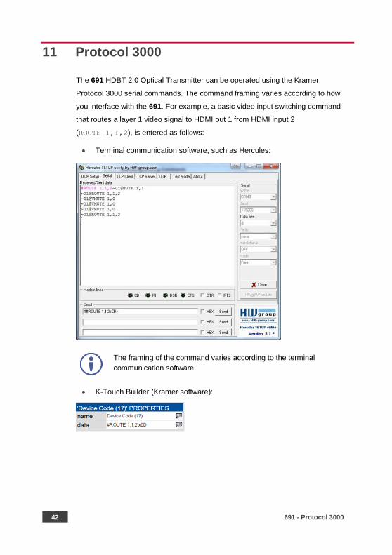
11 Protocol 3000
The 691 HDBT 2.0 Optical Transmitter can be operated using the Kramer
Protocol 3000 serial commands. The command framing varies according to how
you interface with the 691. For example, a basic video input switching command
that routes a layer 1 video signal to HDMI out 1 from HDMI input 2
(ROUTE 1,1,2), is entered as follows:
• Terminal communication software, such as Hercules:
The framing of the command varies according to the terminal
communication software.
• K-Touch Builder (Kramer software):
691 - Protocol 3000 43
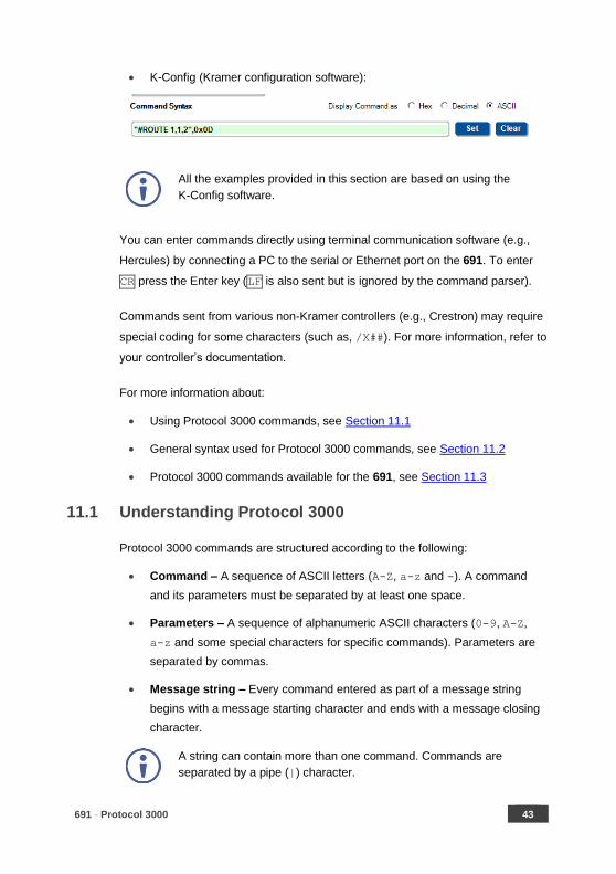
• K-Config (Kramer configuration software):
All the examples provided in this section are based on using the
K-Config software.
You can enter commands directly using terminal communication software (e.g.,
Hercules) by connecting a PC to the serial or Ethernet port on the 691. To enter
CR press the Enter key (LF is also sent but is ignored by the command parser).
Commands sent from various non-Kramer controllers (e.g., Crestron) may require
special coding for some characters (such as, /X##). For more information, refer to
your controller’s documentation.
For more information about:
• Using Protocol 3000 commands, see Section 11.1
• General syntax used for Protocol 3000 commands, see Section 11.2
• Protocol 3000 commands available for the 691, see Section 11.3
11.1 Understanding Protocol 3000
Protocol 3000 commands are structured according to the following:
• Command – A sequence of ASCII letters (A-Z, a-z and -). A command
and its parameters must be separated by at least one space.
• Parameters – A sequence of alphanumeric ASCII characters (0-9, A-Z,
a-z and some special characters for specific commands). Parameters are
separated by commas.
• Message string – Every command entered as part of a message string
begins with a message starting character and ends with a message closing
character.
A string can contain more than one command. Commands are
separated by a pipe (|) character.

44 691 - Protocol 3000
The maximum string length is 64 characters.
• Message starting character:
# – For host command/query
~ – For device response
• Device address – K-NET Device ID followed by @ (optional, K-NET only)
• Query sign – ? follows some commands to define a query request
• Message closing character:
CR – Carriage return for host messages (ASCII 13)
CR LF – Carriage return for device messages (ASCII 13) and line-feed
(ASCII 10)
• Command chain separator character – Multiple commands can be
chained in the same string. Each command is delimited by a pipe character
(|). When chaining commands, enter the message starting character and
the message closing character only at the beginning and end of the string.
Spaces between parameters or command terms are ignored.
Commands in the string do not execute until the closing character is
entered. A separate response is sent for every command in the
chain.
691 - Protocol 3000 45
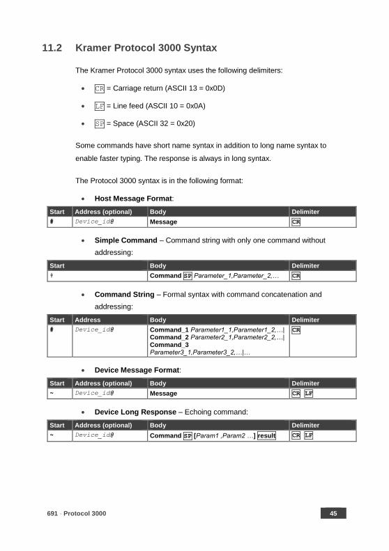
11.2 Kramer Protocol 3000 Syntax
The Kramer Protocol 3000 syntax uses the following delimiters:
• CR = Carriage return (ASCII 13 = 0x0D)
• LF = Line feed (ASCII 10 = 0x0A)
• SP = Space (ASCII 32 = 0x20)
Some commands have short name syntax in addition to long name syntax to
enable faster typing. The response is always in long syntax.
The Protocol 3000 syntax is in the following format:
• Host Message Format:
Start Address (optional) Body Delimiter
# Device_id@ Message CR
• Simple Command – Command string with only one command without
addressing:
Start Body Delimiter
# Command SP Parameter_1,Parameter_2,… CR
• Command String – Formal syntax with command concatenation and
addressing:
Start Address Body Delimiter
# Device_id@ Command_1 Parameter1_1,Parameter1_2,…| Command_2 Parameter2_1,Parameter2_2,…| Command_3 Parameter3_1,Parameter3_2,…|…
CR
• Device Message Format:
Start Address (optional) Body Delimiter
~ Device_id@ Message CR LF
• Device Long Response – Echoing command:
Start Address (optional) Body Delimiter
~ Device_id@ Command SP [Param1 ,Param2 …] result CR LF

46 691 - Protocol 3000
11.3 Protocol 3000 Commands
This section includes the following commands:
• System Commands (see Section 11.3.1)
• Authentication Commands (see Section 11.3.2)
• Audio Commands (see Section 11.3.3)
• Communication Commands (see Section 11.3.4)
• EDID Handling Commands (see Section 11.3.5)
• Administrator Commands (see Section 11.3.6)
11.3.1 System Commands
Command Description
# Protocol handshaking (system mandatory)
BUILD-DATE Get device build date (system mandatory)
FACTORY Reset to factory default configuration
HELP Get command list (system mandatory)
MODEL Get device model (system mandatory)
PROT-VER Get device protocol version (system mandatory)
RESET Reset device (system mandatory)
SN Get device serial number (system mandatory)
VERSION Get device firmware version (system mandatory)
AV-SW-MODE Get auto switch mode (system)
AV-SW-TIMEOUT Set/get auto switching timeout (system)
DISPLAY Get output HPD status (system)
DPSW-STATUS Get the DIP-switch status (system)
HDCP-MOD Set/get HDCP mode (system)
HDCP-STAT Get HDCP signal status (system)
NAME Set/get machine (DNS) name (system – Ethernet)
NAME-RST Reset machine (DNS) name to factory default (system – Ethernet)
PRIORITY Get priority for all channels (system)
SIGNAL Get input signal lock status (system)
691 - Protocol 3000 47
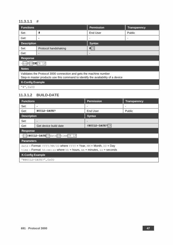
11.3.1.1 #
Functions Permission Transparency
Set: # End User Public
Get: - - -
Description Syntax
Set: Protocol handshaking #CR
Get: - -
Response
~nn@SPOKCR LF
Notes
Validates the Protocol 3000 connection and gets the machine number
Step-in master products use this command to identify the availability of a device
K-Config Example
“#”,0x0D
11.3.1.2 BUILD-DATE
Functions Permission Transparency
Set: - - -
Get: BUILD-DATE? End User Public
Description Syntax
Set: - -
Get: Get device build date #BUILD-DATE?CR
Response
~nn@BUILD-DATESPdateSPtimeCR LF
Parameters
date – Format: YYYY/MM/DD where YYYY = Year, MM = Month, DD = Day
time – Format: hh:mm:ss where hh = hours, mm = minutes, ss = seconds
K-Config Example
“#BUILD-DATE?”,0x0D
48 691 - Protocol 3000
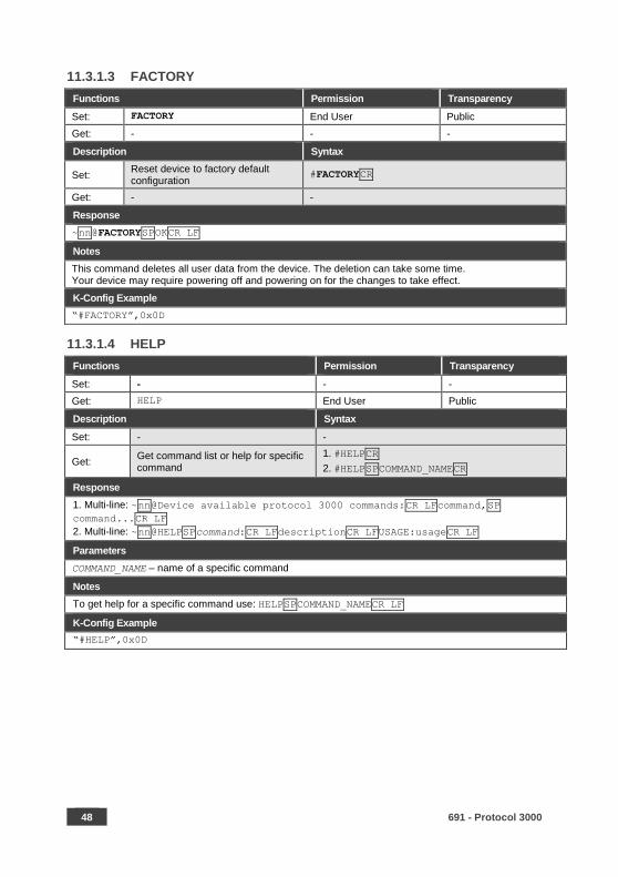
11.3.1.3 FACTORY
Functions Permission Transparency
Set: FACTORY End User Public
Get: - - -
Description Syntax
Set: Reset device to factory default configuration
#FACTORYCR
Get: - -
Response
~nn@FACTORYSPOKCR LF
Notes
This command deletes all user data from the device. The deletion can take some time. Your device may require powering off and powering on for the changes to take effect.
K-Config Example
“#FACTORY”,0x0D
11.3.1.4 HELP
Functions Permission Transparency
Set: - - -
Get: HELP End User Public
Description Syntax
Set: - -
Get: Get command list or help for specific command
1. #HELPCR
2. #HELPSPCOMMAND_NAMECR
Response
1. Multi-line: ~nn@Device available protocol 3000 commands:CR LFcommand,SP
command...CR LF
2. Multi-line: ~nn@HELPSPcommand:CR LFdescriptionCR LFUSAGE:usageCR LF
Parameters
COMMAND_NAME – name of a specific command
Notes
To get help for a specific command use: HELPSPCOMMAND_NAMECR LF
K-Config Example
“#HELP”,0x0D
691 - Protocol 3000 49
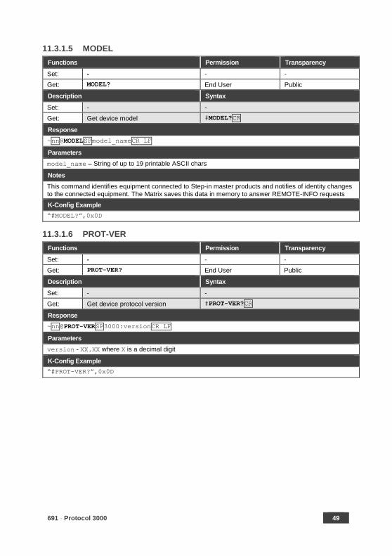
11.3.1.5 MODEL
Functions Permission Transparency
Set: - - -
Get: MODEL? End User Public
Description Syntax
Set: - -
Get: Get device model #MODEL?CR
Response
~nn@MODELSPmodel_nameCR LF
Parameters
model_name – String of up to 19 printable ASCII chars
Notes
This command identifies equipment connected to Step-in master products and notifies of identity changes to the connected equipment. The Matrix saves this data in memory to answer REMOTE-INFO requests
K-Config Example
“#MODEL?”,0x0D
11.3.1.6 PROT-VER
Functions Permission Transparency
Set: - - -
Get: PROT-VER? End User Public
Description Syntax
Set: - -
Get: Get device protocol version #PROT-VER?CR
Response
~nn@PROT-VERSP3000:versionCR LF
Parameters
version - XX.XX where X is a decimal digit
K-Config Example
“#PROT-VER?”,0x0D
50 691 - Protocol 3000
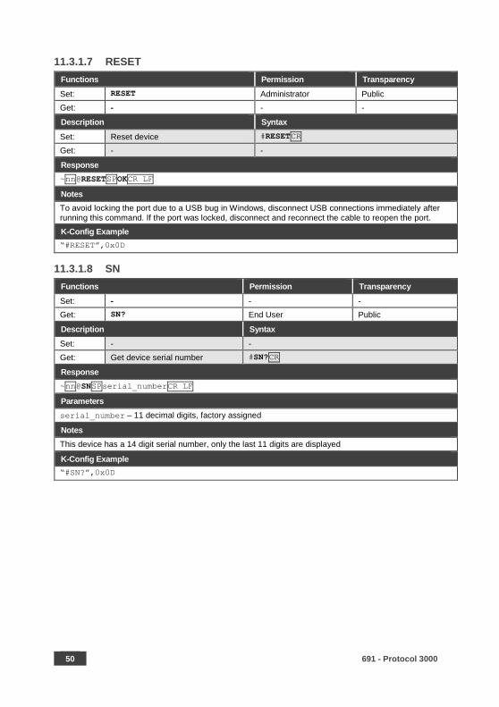
11.3.1.7 RESET
Functions Permission Transparency
Set: RESET Administrator Public
Get: - - -
Description Syntax
Set: Reset device #RESETCR
Get: - -
Response
~nn@RESETSPOKCR LF
Notes
To avoid locking the port due to a USB bug in Windows, disconnect USB connections immediately after running this command. If the port was locked, disconnect and reconnect the cable to reopen the port.
K-Config Example
“#RESET”,0x0D
11.3.1.8 SN
Functions Permission Transparency
Set: - - -
Get: SN? End User Public
Description Syntax
Set: - -
Get: Get device serial number #SN?CR
Response
~nn@SNSPserial_numberCR LF
Parameters
serial_number – 11 decimal digits, factory assigned
Notes
This device has a 14 digit serial number, only the last 11 digits are displayed
K-Config Example
“#SN?”,0x0D
691 - Protocol 3000 51
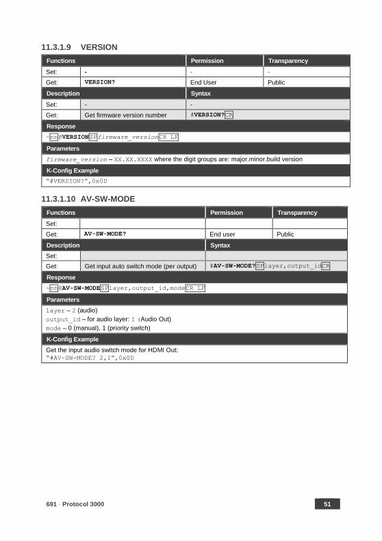
11.3.1.9 VERSION
Functions Permission Transparency
Set: - - -
Get: VERSION? End User Public
Description Syntax
Set: - -
Get: Get firmware version number #VERSION?CR
Response
~nn@VERSIONSPfirmware_versionCR LF
Parameters
firmware_version – XX.XX.XXXX where the digit groups are: major.minor.build version
K-Config Example
“#VERSION?”,0x0D
11.3.1.10 AV-SW-MODE
Functions Permission Transparency
Set:
Get: AV-SW-MODE? End user Public
Description Syntax
Set:
Get: Get input auto switch mode (per output) #AV-SW-MODE?SPlayer,output_idCR
Response
~nn@AV-SW-MODESPlayer,output_id,modeCR LF
Parameters
layer – 2 (audio)
output_id – for audio layer: 1 (Audio Out)
mode – 0 (manual), 1 (priority switch)
K-Config Example
Get the input audio switch mode for HDMI Out:
“#AV-SW-MODE? 2,1”,0x0D

52 691 - Protocol 3000
11.3.1.11 AV-SW-TIMEOUT
Functions Permission Transparency
Set: AV-SW-TIMEOUT End User Public
Get: AV-SW-TIMEOUT? End User Public
Description Syntax
Set: Set auto switching timeout #AV-SW-TIMEOUTSPaction,time_outCR
Get: Get auto switching timeout #AV-SW-TIMEOUT?SPactionCR
Response
~nn@AV-SW-TIMEOUTSPaction,time_outCR
Parameters
action – event that triggers the auto switching timeout:
2 (audio signal lost)
3 (Audio signal detected)
4 (disable 5V on video output if no input signal detected)
6 (audio cable unplugged)
timeout – timeout in seconds: 0-60000
Notes
The timeout must not exceed 60000 seconds.
K-Config Example
Set the auto switching timeout to 5 seconds in the event of no input signal detected: “#AV-SW-TIMEOUT 4,5”,0x0D
11.3.1.12 DISPLAY
Functions Permission Transparency
Set: - - -
Get DISPLAY? End User Public
Description Syntax
Set: - -
Get: Get output HPD status #DISPLAY?SPout_idCR
Response
~nn@DISPLAYSPout_id,statusCR LF
Parameters
out_id – 1 (Out)=
status – HPD status according to signal validation : 0 (Off), 1 (On), 2 (On and all parameters are stable
and valid)
Response Triggers
A response is sent to the com port from which the Get was received, after command execution and:
After every change in output HPD status from On to Off (0)
After every change in output HPD status from Off to On (1)
After every change in output HPD status form Off to On and all parameters (new EDID, etc.) are stable and valid (2)
K-Config Example
Get the output HPD status of HDMI Out:
“#DISPLAY? 1”,0x0D
691 - Protocol 3000 53
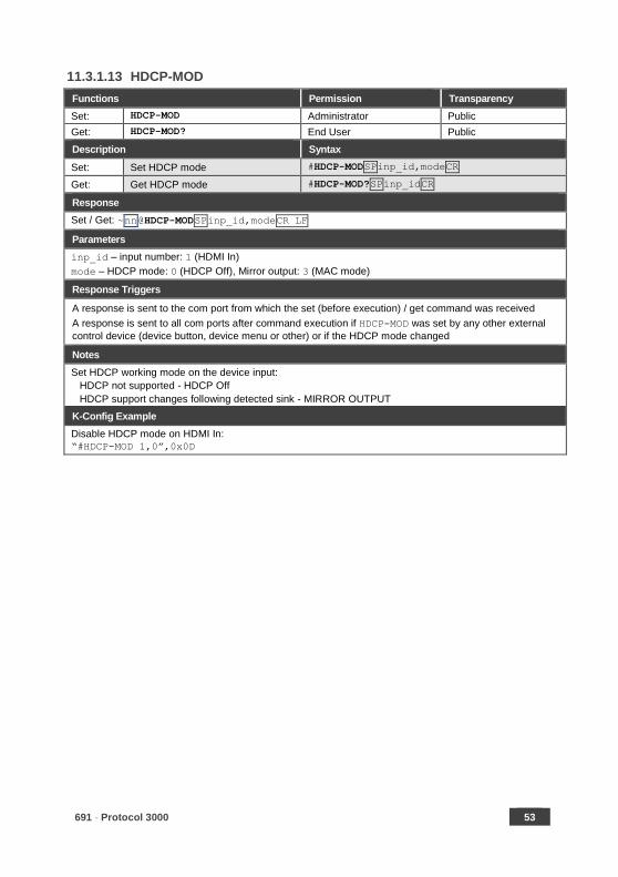
11.3.1.13 HDCP-MOD
Functions Permission Transparency
Set: HDCP-MOD Administrator Public
Get: HDCP-MOD? End User Public
Description Syntax
Set: Set HDCP mode #HDCP-MODSPinp_id,modeCR
Get: Get HDCP mode #HDCP-MOD?SPinp_idCR
Response
Set / Get: ~nn@HDCP-MODSPinp_id,modeCR LF
Parameters
inp_id – input number: 1 (HDMI In)
mode – HDCP mode: 0 (HDCP Off), Mirror output: 3 (MAC mode)
Response Triggers
A response is sent to the com port from which the set (before execution) / get command was received
A response is sent to all com ports after command execution if HDCP-MOD was set by any other external
control device (device button, device menu or other) or if the HDCP mode changed
Notes
Set HDCP working mode on the device input:
HDCP not supported - HDCP Off
HDCP support changes following detected sink - MIRROR OUTPUT
K-Config Example
Disable HDCP mode on HDMI In:
“#HDCP-MOD 1,0”,0x0D

54 691 - Protocol 3000
11.3.1.14 HDCP-STAT
Functions Permission Transparency
Set: - - -
Get: HDCP-STAT? End User Public
Description Syntax
Set: - -
Get: Get HDCP signal status #HDCP-STAT?SPstage,stage_idCR
Response
~ nn@HDCP-STATSPstage,stage_id,statusCR LF
Parameters
stage – 0 (input), 1 (output)
stage_id – for input stage: 1 (HDMI In), for output stage: 1 (HDMI Out) status – signal encryption status: 0 (On), 1 (Off)
Response Triggers
A response is sent to the com port from which the Get command was received
Notes
Output stage (1) – get the HDCP signal status of the sink device connected to HDMI Out
Input stage (0) – get the HDCP signal status of the source device connected to the specified input
K-Config Example
Get the HDCP input signal status of the source device connected to HDMI In:
“#HDCP-STAT? 0,1”,0x0D
11.3.1.15 NAME
Functions Permission Transparency
Set: NAME Administrator Public
Get: NAME? End User Public
Description Syntax
Set: Set machine (DNS) name #NAMESPmachine_nameCR
Get: Get machine (DNS) name #NAME?CR
Response
Set: ~nn@NAMESPmachine_nameCR LF
Get: ~nn@NAME?SPmachine_nameCR LF
Parameters
machine_name – String of up to 14 alpha-numeric characters (can include hyphens but not at the
beginning or end)
Notes
The machine name is not the same as the model name. The machine name is used to identify a specific machine or a network in use (with DNS feature on).
K-Config Example
Set the DNS name of the device to “room-442”:
“#NAME room-442”,0x0D
691 - Protocol 3000 55
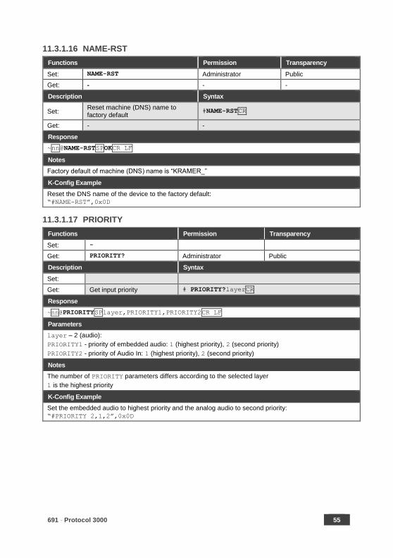
11.3.1.16 NAME-RST
Functions Permission Transparency
Set: NAME-RST Administrator Public
Get: - - -
Description Syntax
Set: Reset machine (DNS) name to factory default
#NAME-RSTCR
Get: - -
Response
~nn@NAME-RSTSPOKCR LF
Notes
Factory default of machine (DNS) name is “KRAMER_”
K-Config Example
Reset the DNS name of the device to the factory default:
“#NAME-RST”,0x0D
11.3.1.17 PRIORITY
Functions Permission Transparency
Set: -
Get: PRIORITY? Administrator Public
Description Syntax
Set:
Get: Get input priority # PRIORITY?layerCR
Response
~nn@PRIORITYSPlayer,PRIORITY1,PRIORITY2CR LF
Parameters
layer – 2 (audio):
PRIORITY1 - priority of embedded audio: 1 (highest priority), 2 (second priority)
PRIORITY2 - priority of Audio In: 1 (highest priority), 2 (second priority)
Notes
The number of PRIORITY parameters differs according to the selected layer
1 is the highest priority
K-Config Example
Set the embedded audio to highest priority and the analog audio to second priority:
“#PRIORITY 2,1,2”,0x0D
56 691 - Protocol 3000
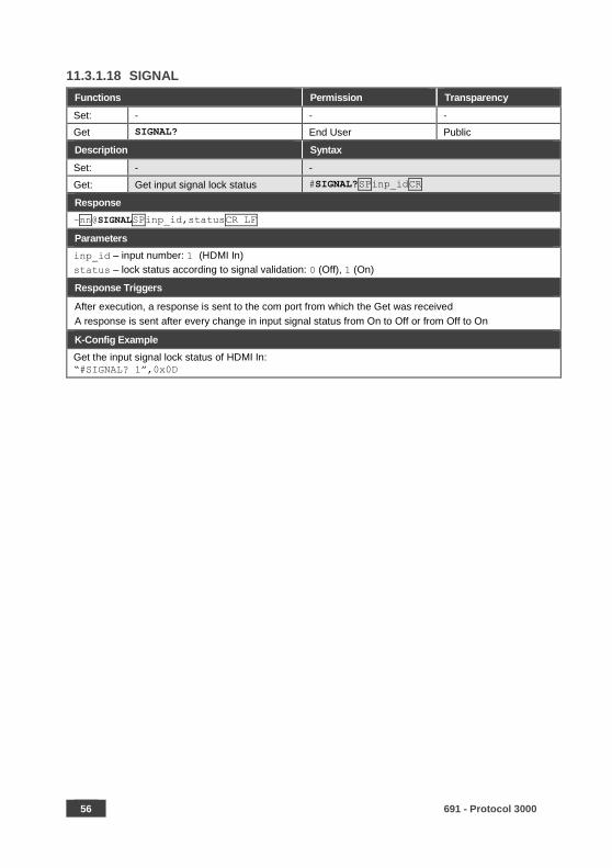
11.3.1.18 SIGNAL
Functions Permission Transparency
Set: - - -
Get SIGNAL? End User Public
Description Syntax
Set: - -
Get: Get input signal lock status #SIGNAL?SPinp_idCR
Response
~nn@SIGNALSPinp_id,statusCR LF
Parameters
inp_id – input number: 1 (HDMI In)
status – lock status according to signal validation: 0 (Off), 1 (On)
Response Triggers
After execution, a response is sent to the com port from which the Get was received
A response is sent after every change in input signal status from On to Off or from Off to On
K-Config Example
Get the input signal lock status of HDMI In: “#SIGNAL? 1”,0x0D
691 - Protocol 3000 57
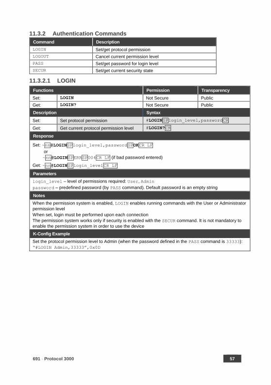
11.3.2 Authentication Commands
Command Description
LOGIN Set/get protocol permission
LOGOUT Cancel current permission level
PASS Set/get password for login level
SECUR Set/get current security state
11.3.2.1 LOGIN
Functions Permission Transparency
Set: LOGIN Not Secure Public
Get: LOGIN? Not Secure Public
Description Syntax
Set: Set protocol permission #LOGINSPlogin_level,passwordCR
Get: Get current protocol permission level #LOGIN?CR
Response
Set: ~nn@LOGINSPlogin_level,passwordSPOKCR LF
or
~nn@LOGINSPERRSP004CR LF (if bad password entered)
Get: ~nn@LOGINSPlogin_levelCR LF
Parameters
login_level – level of permissions required: User, Admin
password – predefined password (by PASS command). Default password is an empty string
Notes
When the permission system is enabled, LOGIN enables running commands with the User or Administrator
permission level
When set, login must be performed upon each connection
The permission system works only if security is enabled with the SECUR command. It is not mandatory to
enable the permission system in order to use the device
K-Config Example
Set the protocol permission level to Admin (when the password defined in the PASS command is 33333):
“#LOGIN Admin,33333”,0x0D

58 691 - Protocol 3000
11.3.2.2 LOGOUT
Functions Permission Transparency
Set: LOGOUT Not Secure Public
Get: - - -
Description Syntax
Set: Cancel current permission level #LOGOUTCR
Get: - -
Response
~nn@LOGOUTSPOKCR LF
Notes
Logs out from User or Administrator permission levels
K-Config Example
“#LOGOUT”,0x0D
11.3.2.3 PASS
Functions Permission Transparency
Set: PASS Administrator Public
Get: PASS? Administrator Public
Description Syntax
Set: Set password for login level #PASSSPlogin_level,passwordCR
Get: Get password for login level #PASS?SPlogin_levelCR
Response
~nn@PASSSPlogin_level,passwordCR LF
Parameters
login_level – level of login to set: User, Admin
password – password for the login_level. Up to 15 printable ASCII chars.
Notes
The default password is an empty string
K-Config Example
Set the password for the Admin protocol permission level to 33333:
“#PASS Admin,33333”,0x0D
691 - Protocol 3000 59
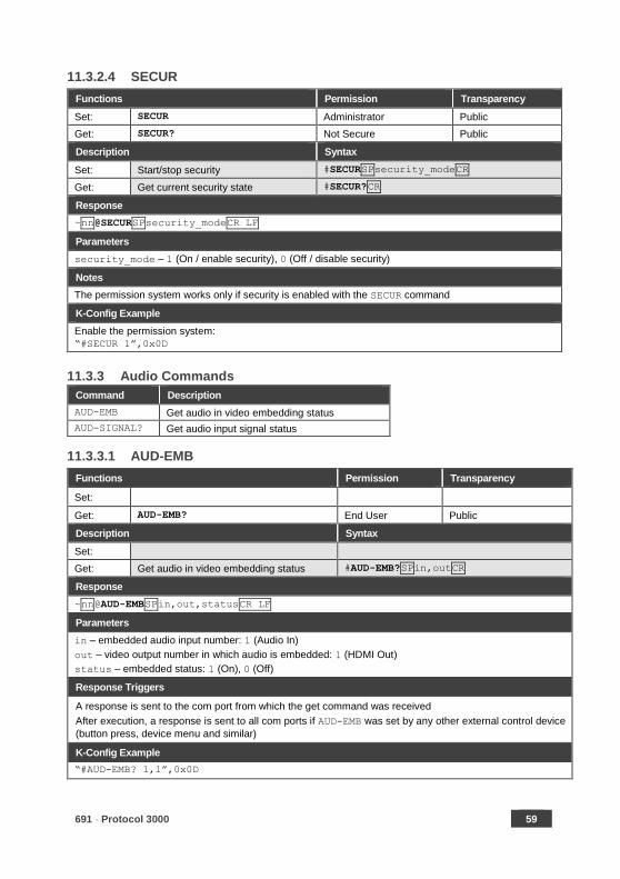
11.3.2.4 SECUR
Functions Permission Transparency
Set: SECUR Administrator Public
Get: SECUR? Not Secure Public
Description Syntax
Set: Start/stop security #SECURSPsecurity_modeCR
Get: Get current security state #SECUR?CR
Response
~nn@SECURSPsecurity_modeCR LF
Parameters
security_mode – 1 (On / enable security), 0 (Off / disable security)
Notes
The permission system works only if security is enabled with the SECUR command
K-Config Example
Enable the permission system:
“#SECUR 1”,0x0D
11.3.3 Audio Commands
Command Description
AUD-EMB Get audio in video embedding status
AUD-SIGNAL? Get audio input signal status
11.3.3.1 AUD-EMB
Functions Permission Transparency
Set:
Get: AUD-EMB? End User Public
Description Syntax
Set:
Get: Get audio in video embedding status #AUD-EMB?SPin,outCR
Response
~nn@AUD-EMBSPin,out,statusCR LF
Parameters
in – embedded audio input number: 1 (Audio In)
out – video output number in which audio is embedded: 1 (HDMI Out)
status – embedded status: 1 (On), 0 (Off)
Response Triggers
A response is sent to the com port from which the get command was received
After execution, a response is sent to all com ports if AUD-EMB was set by any other external control device
(button press, device menu and similar)
K-Config Example
“#AUD-EMB? 1,1”,0x0D

60 691 - Protocol 3000
11.3.3.2 AUD-SIGNAL
Functions Permission Transparency
Set: - - -
Get AUD-SIGNAL? End User Public
Description Syntax
Set: - -
Get: Get audio input signal status # AUD-SIGNAL?SPinp_idCR
Response
~nn@AUD-SIGNALSPinp_id,statusCR LF
Parameters
inp_id – audio input number: 1 (Audio In) status – 0 (Off / no signal), 1 (On / signal present)
Response Triggers
After execution, a response is sent to the com port from which the get command was received
A response is sent to all com ports if the audio status was changed on any input
K-Config Example
“#AUD-SIGNAL? 1”,0x0D
691 - Protocol 3000 61
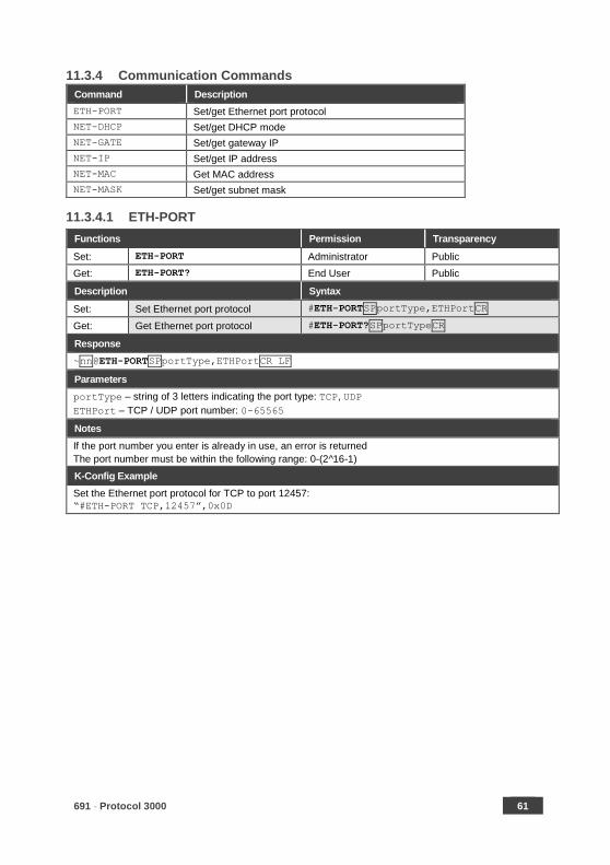
11.3.4 Communication Commands
Command Description
ETH-PORT Set/get Ethernet port protocol
NET-DHCP Set/get DHCP mode
NET-GATE Set/get gateway IP
NET-IP Set/get IP address
NET-MAC Get MAC address
NET-MASK Set/get subnet mask
11.3.4.1 ETH-PORT
Functions Permission Transparency
Set: ETH-PORT Administrator Public
Get: ETH-PORT? End User Public
Description Syntax
Set: Set Ethernet port protocol #ETH-PORTSPportType,ETHPortCR
Get: Get Ethernet port protocol #ETH-PORT?SPportTypeCR
Response
~nn@ETH-PORTSPportType,ETHPortCR LF
Parameters
portType – string of 3 letters indicating the port type: TCP, UDP
ETHPort – TCP / UDP port number: 0-65565
Notes
If the port number you enter is already in use, an error is returned
The port number must be within the following range: 0-(2^16-1)
K-Config Example
Set the Ethernet port protocol for TCP to port 12457:
“#ETH-PORT TCP,12457”,0x0D
62 691 - Protocol 3000
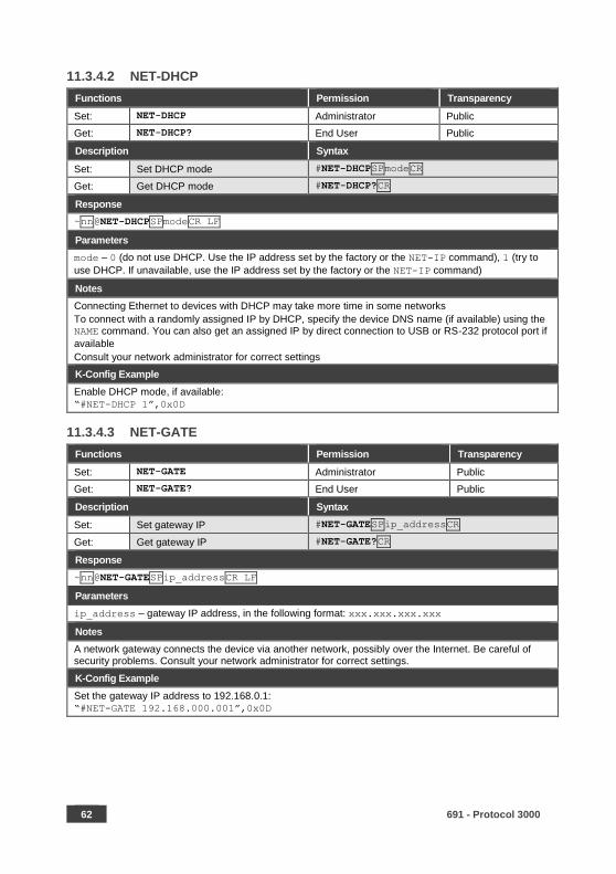
11.3.4.2 NET-DHCP
Functions Permission Transparency
Set: NET-DHCP Administrator Public
Get: NET-DHCP? End User Public
Description Syntax
Set: Set DHCP mode #NET-DHCPSPmodeCR
Get: Get DHCP mode #NET-DHCP?CR
Response
~nn@NET-DHCPSPmodeCR LF
Parameters
mode – 0 (do not use DHCP. Use the IP address set by the factory or the NET-IP command), 1 (try to
use DHCP. If unavailable, use the IP address set by the factory or the NET-IP command)
Notes
Connecting Ethernet to devices with DHCP may take more time in some networks
To connect with a randomly assigned IP by DHCP, specify the device DNS name (if available) using the NAME command. You can also get an assigned IP by direct connection to USB or RS-232 protocol port if
available
Consult your network administrator for correct settings
K-Config Example
Enable DHCP mode, if available:
“#NET-DHCP 1”,0x0D
11.3.4.3 NET-GATE
Functions Permission Transparency
Set: NET-GATE Administrator Public
Get: NET-GATE? End User Public
Description Syntax
Set: Set gateway IP #NET-GATESPip_addressCR
Get: Get gateway IP #NET-GATE?CR
Response
~nn@NET-GATESPip_addressCR LF
Parameters
ip_address – gateway IP address, in the following format: xxx.xxx.xxx.xxx
Notes
A network gateway connects the device via another network, possibly over the Internet. Be careful of security problems. Consult your network administrator for correct settings.
K-Config Example
Set the gateway IP address to 192.168.0.1: “#NET-GATE 192.168.000.001”,0x0D
691 - Protocol 3000 63
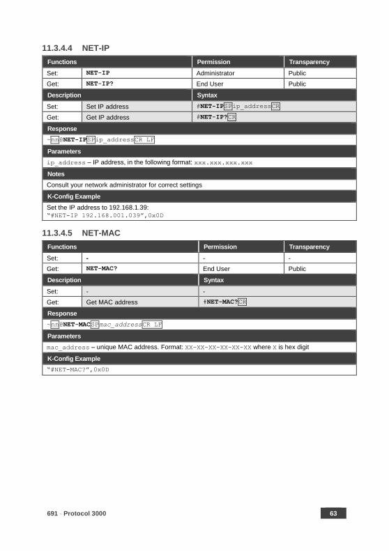
11.3.4.4 NET-IP
Functions Permission Transparency
Set: NET-IP Administrator Public
Get: NET-IP? End User Public
Description Syntax
Set: Set IP address #NET-IPSPip_addressCR
Get: Get IP address #NET-IP?CR
Response
~nn@NET-IPSPip_addressCR LF
Parameters
ip_address – IP address, in the following format: xxx.xxx.xxx.xxx
Notes
Consult your network administrator for correct settings
K-Config Example
Set the IP address to 192.168.1.39:
“#NET-IP 192.168.001.039”,0x0D
11.3.4.5 NET-MAC
Functions Permission Transparency
Set: - - -
Get: NET-MAC? End User Public
Description Syntax
Set: - -
Get: Get MAC address #NET-MAC?CR
Response
~nn@NET-MACSPmac_addressCR LF
Parameters
mac_address – unique MAC address. Format: XX-XX-XX-XX-XX-XX where X is hex digit
K-Config Example
“#NET-MAC?”,0x0D
64 691 - Protocol 3000
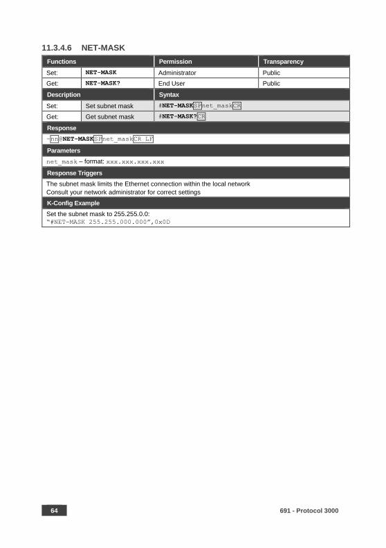
11.3.4.6 NET-MASK
Functions Permission Transparency
Set: NET-MASK Administrator Public
Get: NET-MASK? End User Public
Description Syntax
Set: Set subnet mask #NET-MASKSPnet_maskCR
Get: Get subnet mask #NET-MASK?CR
Response
~nn@NET-MASKSPnet_maskCR LF
Parameters
net_mask – format: xxx.xxx.xxx.xxx
Response Triggers
The subnet mask limits the Ethernet connection within the local network
Consult your network administrator for correct settings
K-Config Example
Set the subnet mask to 255.255.0.0:
“#NET-MASK 255.255.000.000”,0x0D
691 - Protocol 3000 65
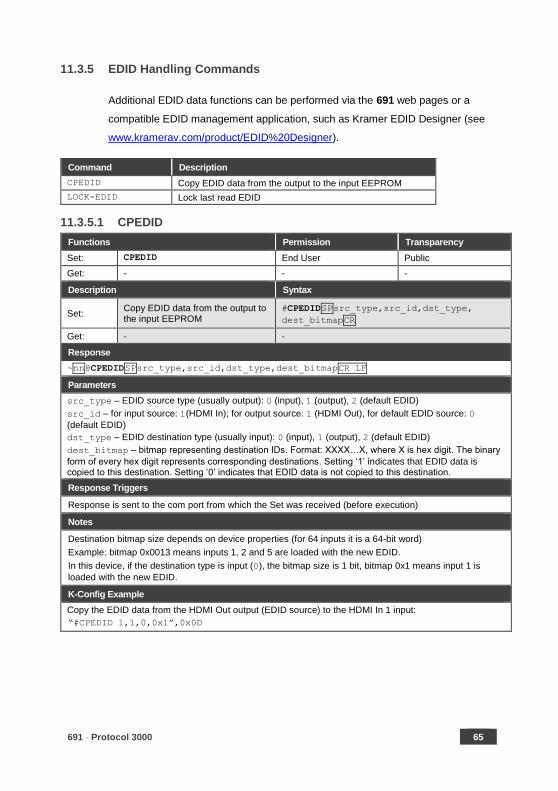
11.3.5 EDID Handling Commands
Additional EDID data functions can be performed via the 691 web pages or a
compatible EDID management application, such as Kramer EDID Designer (see
www.kramerav.com/product/EDID%20Designer).
Command Description
CPEDID Copy EDID data from the output to the input EEPROM
LOCK-EDID Lock last read EDID
11.3.5.1 CPEDID
Functions Permission Transparency
Set: CPEDID End User Public
Get: - - -
Description Syntax
Set: Copy EDID data from the output to the input EEPROM
#CPEDIDSPsrc_type,src_id,dst_type,
dest_bitmapCR
Get: - -
Response
~nn@CPEDIDSPsrc_type,src_id,dst_type,dest_bitmapCR LF
Parameters
src_type – EDID source type (usually output): 0 (input), 1 (output), 2 (default EDID)
src_id – for input source: 1(HDMI In); for output source: 1 (HDMI Out), for default EDID source: 0
(default EDID)
dst_type – EDID destination type (usually input): 0 (input), 1 (output), 2 (default EDID)
dest_bitmap – bitmap representing destination IDs. Format: XXXX…X, where X is hex digit. The binary
form of every hex digit represents corresponding destinations. Setting ‘1’ indicates that EDID data is copied to this destination. Setting ‘0’ indicates that EDID data is not copied to this destination.
Response Triggers
Response is sent to the com port from which the Set was received (before execution)
Notes
Destination bitmap size depends on device properties (for 64 inputs it is a 64-bit word)
Example: bitmap 0x0013 means inputs 1, 2 and 5 are loaded with the new EDID.
In this device, if the destination type is input (0), the bitmap size is 1 bit, bitmap 0x1 means input 1 is
loaded with the new EDID.
K-Config Example
Copy the EDID data from the HDMI Out output (EDID source) to the HDMI In 1 input:
“#CPEDID 1,1,0,0x1”,0x0D
66 691 - Protocol 3000
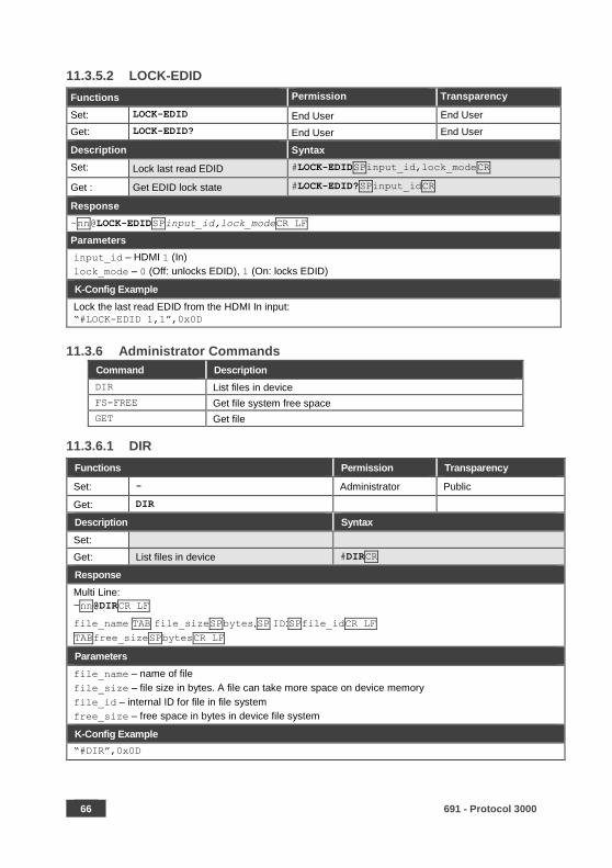
11.3.5.2 LOCK-EDID
Functions Permission Transparency
Set: LOCK-EDID End User End User
Get: LOCK-EDID? End User End User
Description Syntax
Set: Lock last read EDID #LOCK-EDIDSPinput_id,lock_modeCR
Get : Get EDID lock state #LOCK-EDID?SPinput_idCR
Response
~nn@LOCK-EDIDSPinput_id,lock_modeCR LF
Parameters
input_id – HDMI 1 (In)
lock_mode – 0 (Off: unlocks EDID), 1 (On: locks EDID)
K-Config Example
Lock the last read EDID from the HDMI In input:
“#LOCK-EDID 1,1”,0x0D
11.3.6 Administrator Commands
Command Description
DIR List files in device
FS-FREE Get file system free space
GET Get file
11.3.6.1 DIR
Functions Permission Transparency
Set: - Administrator Public
Get: DIR
Description Syntax
Set:
Get: List files in device #DIRCR
Response
Multi Line:
~nn@DIRCR LF
file_name TAB file_sizeSPbytes,SP ID:SPfile_idCR LF
TABfree_sizeSPbytesCR LF
Parameters
file_name – name of file
file_size – file size in bytes. A file can take more space on device memory
file_id – internal ID for file in file system
free_size – free space in bytes in device file system
K-Config Example
“#DIR”,0x0D
691 - Protocol 3000 67
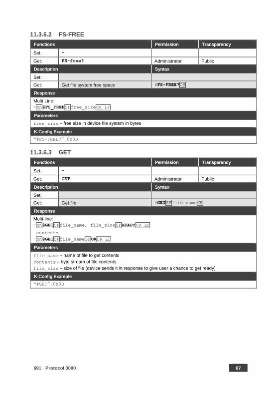
11.3.6.2 FS-FREE
Functions Permission Transparency
Set: -
Get: FS-free? Administrator Public
Description Syntax
Set:
Get: Get file system free space #FS-FREE?CR
Response
Multi Line:
~nn@FS_FREESPfree_sizeCR LF
Parameters
free_size – free size in device file system in bytes
K-Config Example
“#FS-FREE?”,0x0D
11.3.6.3 GET
Functions Permission Transparency
Set: -
Get: GET Administrator Public
Description Syntax
Set:
Get: Get file #GETSPfile_nameCR
Response
Multi-line:
~nn@GETSPfile_name, file_sizeSPREADYCR LF
contents
~nn@GETSPfile_nameSPOKCR LF
Parameters
file_name – name of file to get contents
contents – byte stream of file contents
file_size – size of file (device sends it in response to give user a chance to get ready)
K-Config Example
“#GET”,0x0D

P/N: 2900- 300523 Rev: 3
SAFETY WARNING
Disconnect the unit from the power supply before opening and servicing
For the latest information on our products and a list of Kramer distributors,
visit our Web site where updates to this user manual may be found.
We welcome your questions, comments, and feedback.
www.KramerAV.com [email protected]