USER MANUAL - Racurs ·...
22
Digital Photogrammetric System Version 6.3 USER MANUAL Orthorectification
Transcript of USER MANUAL - Racurs ·...
Digital Photogrammetric System
Version 6.3
USER MANUALOrthorectification

Table of Contents1. Purpose of the document .......................................................................................................... 32. General information .................................................................................................................. 33. The “Orthorectification” toolbar .................................................................................................. 34. “FastOrtho” displaying ............................................................................................................... 45. Orthoimages creation ............................................................................................................... 46. Settings of orthorectification parameters .................................................................................... 7
6.1. Type of DTM ................................................................................................................. 76.2. General orthoimages creation parameters ..................................................................... 106.3. Output orthoimages parameters .................................................................................... 13
7. Orthoimages creating in distributed processing mode ............................................................... 168. Accuracy control ..................................................................................................................... 18
2
OrthorectificationPHOTOMOD 6.3

1. Purpose of the documentThis document contains detailed information about orthorectification images and orthoim-ages creation in the PHOTOMOD system.
2. General informationOrthoimage is a georeferenced image prepared from a perspective photograph or otherremotely-sensed data in which displacement of objects due to sensor orientation andterrain relief have been removed.
The system provides possibility of creating orthoimages by source images block. This step allowsto prepare images for further processing and creating mosaic in theGeomosaic programprogram.
During orthorectification the system corrects relief displacement, axial angle, cameradistortion, etc. For images orthorectification it is necessary to specify output orthophotocell size, select output image coordinate system and scale, specify output file formatand georeference type.
Prior to create orthoimages it is necessary to adjust images block (see “Block adjustment” UserManual).
3. The “Orthorectification” toolbarThe Orthorectification toolbar is used for creating orthoimages.
In order to display the toolbar, choose the Rasters › Orthorectification (Ctrl+Alt+M)or click the button on the main toolbar.
Table 1. The ’Orthorectification’ toolbar
FunctionButtonsallows to create the new orthorectification projectallows to open an orthorectification project from active profile resourcesallows to save an orthorectification projectallows to save an orthorectification project with a new nameallows to set the orthorectification parametersallows to set the percent of trim image edges during orthorectificationallows to perform the accuracy control of orthorectificationallows to start of orthoimages building and creation of output file for selected sheetallows to start orthoimages creation for specified active sheets considering usersettings and parameters in distributed processing modeallows to start of orthoimages building in the MegaTIFF format using the distributedprocessing modeallows to create a separate layer with orthoimage for each of selected images (seeSection 4)
3
OrthorectificationPHOTOMOD 6.3

FunctionButtonsallows to show general information about project (number of images channels, byteper channel, number of images and output size of mosaic)allows to move to previous image in a block scheme. The first image of the first stripopens if the block scheme 2D-window is activeallows to open selected in 2D-window of a block scheme image in a separate windowallows to move to next image in a block scheme. The last image of the last stripopens if the block scheme 2D-window is activeallows to close all separate raster FastOrtho layers
4. “FastOrtho” displayingThe system provides possibility to quick display and create of orthoimages “FastOrtho”separately for each of selected images.
FastOrtho is used to display orthoimage, created “on fly” by adjustment results. At thatthe pyramid level of image is used, depending on current zoom. These orthoimagesallows to preliminary (rough) estimate data quality.
FastOrtho could be created only on a block with adjustment in geodetic coordinate system.
Orthorectification images “in fly” is used to display orthoimage in 2D-window for anyselected image of project.
Perform the following actions to create orthoimages “on fly”:
1. Perform the block adjustment in a geodetic coordinates (see the “Block adjustment”User Manual).
2. [optional] Select images for FastOrtho in 2D-window (more details see in the Vectorobjects selection chapter in the “Vectorization” User Manual).
3. Click the button of the Orthorectification toolbar. Separate raster FastOrtholayer creates for each of selected images. Orthoimage displays in 2D-window.
5. Orthoimages creationPerform the following actions to create orthoimages:
1. Adjust the source images block (see the “Block adjustment” User Manual).
2. [optional] Select images for orthorectification in 2D-window (more details see in theVector objects selection chapter in the “Vectorization” User Manual).
3. Choose the Rasters › Orthorectification. The Orthorectification toolbar opens.
4
OrthorectificationPHOTOMOD 6.3

4. Click the button. The Orthoimages parameters window opens.
Fig. 1. The Orthorectification parameters
5. Set the orthorectification parameters.
6. Click OK to save parameters.
7. Click the of the Orthorectification toolbar to save the orthoimages project.
5
OrthorectificationPHOTOMOD 6.3

8. Click the button of the Orthorectification toolbar. The Output window opens.
For orthorectification in distributed processing mode, click the button. For orthorectific-ation in MegaTIFF format in distributed processing mode , click the button.
Fig. 2. Output parameters
9. Choose File type for output files and define path for files.
10. [optional] If some images are selected on a block scheme, choose Images for ortho:
• All from current PHOTOMOD project:
• Selected on the block scheme.
11. [optional] If in the File type list chosen the Panorama raster (*.RSW) type, thePanorama map selection window opens.
Fig. 3. Parameters of Panorama map export
Set name and path for the map file with one of the following ways:
• click the button to export the map *.sit-file;
6
OrthorectificationPHOTOMOD 6.3

• click the Create button to create a new Panorama map (*.sit), input filenameand click the Save button.
• to export DEM that is used in orthomap creation, set on the Export DEM toPanorama map checkbox.
12. Click OK to start process of orthorectification.
The orthoimage and georeference files are created in the project’s folder in chosenformats.
6. Settings of orthorectification parameters
6.1. Type of DTM
The Type of DTM tab allows to choose method of using DTM and breaklines duringthe orthoimages creating.
7
OrthorectificationPHOTOMOD 6.3

Fig. 4. The ortoretrification parameters on the ’Type of DTM’ tab
The Type of DTM section allows to set the following parameters of DTM using:
• Constant elevation – allows to use constant relief elevation during the orthoinagescreating and fit elevation in one value from the input field;
Default value is mean elevation value calculated from all source images block.
8
OrthorectificationPHOTOMOD 6.3

• Control points interpolation – smooth polynomial model calculated by groundcontrol and tie points is used in orthorectification process (see the “Block adjustment”User Manual);
• DEM – allows to use information from DEM (see the “DTMGeneration” User Manual).
To form the list of DEM there is a toolbox, which contains the following buttons:
○ – allows to clear the DEM list;
○ – allows to add DEM in the list;
○ – allows to remove DEM from the list;
○ – allows to add to the list only DEMs loaded to the current project.
The Layers selection window is opened. It contains all DEM layers loaded to the currentproject. You can select multiple DEMs at once to be added to the list.
○ – allows to create a new layer with copy of DEM selected in the list.
Select only one file with DEM data in the list and click the Open in a new layer button( ).
○ – allows to move selected DEM at the head of the list;
○ – allows to move selected DEM up the list;
○ – allows to move selected DEM down the list;
○ – allows to move selected DEM at the end of the list;
○ – allows to inverts selected DEM in the list;
○ – allows to reverse the DEM order.
• TheCut images by DEM checkbox allows to create orthoimages by rectangle borderconsidering using DEM and without considering the rest area of image.
• The NULL cells interpolation allows to define area out of DEM:
○ None – NULL cells are not used in orthorectification process;
○ Constant elevation – allows to use constant elevation out of DEM during the or-thoinages creating and fit elevation in one value from the input field;
9
OrthorectificationPHOTOMOD 6.3

○ By triangulation points – smooth polynomial model calculated by triangulationpoints is used in orthorectification process (see the “Block adjustment” UserManual).
• The Insert breaklines allows to set the following parameters of using vector objects:
○ None – orthoimages are creating without using vector objects;
○ Breaklines in relief (bridges, etc.) – orthoimages are creating with breaklines,which allows to define typycal relief forms;
○ Breaklines not in relief (roofs, etc.) – orthoimages are creating with breaklinesout of relief.
• To form the list of vector files there is a toolbox, which contains the following buttons:
○ – allows to clear the file list;
○ – allows to add vector file in the list;
○ – allows to remove vector file file from the list.
○ – allows to add to the list only vector data loaded to the current project.
You can select multiple layers with vector data at once to be added to the list.
○ – allows to create a new layer with copy of vector data.
Select only one file with vector data in the list and click the Open in a new layer button( ).
• The Fill shadow areas by background color checkbox is set in the system by de-fault. If the checkbox is off, shadow areas which become ’visible’ after rectification,are filled in due to interpolation of color values of adjacent pixels.
6.2. General orthoimages creation parameters
TheOrthoimage tab of theOrthoimages parameters window purposes to setup mainoptions of orthoimages creating.
10
OrthorectificationPHOTOMOD 6.3

Fig. 5. General orthoimages parameters
TheOrthoimage tab is used for setting the following parameters of output orthoimages:
• Cell size – allows to specify the size of output orthoimage cell on the terrain. The cellsize by default is equal to the cell size of the first image of project.
The cell size is set in measurement units equal to units of ground control points in the adjust-ment step (see the “Block adjustment” User Manual).
The Compute button allows to set general size of orthoimage in pixels and recalculate thecell size according to set parameters.
11
OrthorectificationPHOTOMOD 6.3

Fig. 6. Orthoimage cell size
• Background color – allows to set a colour for orthoimages background, since outputorthoimages always inscribes into a rectangular of this color.
• Resampling method – allows to choose the brightness interpolation mode duringorthomosaic creation: bilinear, cubic or nearest neighbour;
• Shift background color – allows to specify a shift of colour on the image if this colourcoincides with defined colour of orthoimages background.
• Geometry correction cell size – allows to setup a fragment size (in pixels) whencreating orthoimages using fragments with projective dependence.
The larger the fragment, the faster the mosaic building and the lower the accuracy of outputorthoimages. The value of 32 pixels is optimal for “speed-accuracy” ratio.
• Adaptive geometry correction cell size – allows to adjust theGeometry correctioncell size automatically, according to the topographic features, increasing the speedof orthoimages creation and the accuracy of the areas with rugged topography;
• Output raster channels – opens the window Output image parameters, used forspecifying the following parameters:
By default quantity and structure of channels are defined by first added image.
○ Use radiometric form RMC-files – is used when create orthoimages if in theRaster Converter module was preliminary performed the radiometric correction(see the “General information” User Manual);
○ Channels list – contains list of source (left) and selected for using in orthorectific-ation channels (right);
Quantity and structure of channels are forming with buttons of the Channels list section.
○ Data format – allows to choose the format of image: 8 bit or 16 bit;
12
OrthorectificationPHOTOMOD 6.3

○ Monochrome output – allows to create output file with one grayscale channel.
Fig. 7. Output channels parameters
• Rotation angle – allows to setup a rotation angle (in degrees) of orthoimages.
This option is used if a block of initial images has elongated shape and it is necessary to re-move over background area in rectangular window of created orthoimages.
• Source rasters background color range – allows to set a deviation from backgroundcolor: to specify a range of color, that consider as background in initial images (seethe “Orthophotomaps creation” User Manual);
• Additional check for black background – for areas out of DEM is used a blackbackground in orthoimages creation;
• Transform inside polygons – area of orthorectification is set by arbitrary polygonsfrom a vector file. Choose a file with polygons in active profile resources.
Also the Orthoimage tab allows to choose Input and Output coordinate systems.
6.3. Output orthoimages parameters
The Output tab of the Orthoimages parameters window purposes to setup outputoptions of orthoimages creating.
13
OrthorectificationPHOTOMOD 6.3

Fig. 8. Output orthoimages parameters
The Map scale field allows to set the scale of output orthoimages.
The Calculate map scale button allows to calculate a scale and map sheet size (inmeters) and print resolution (in dpi).
Fig. 9. Map scale
With orthomap in chosen format also could be created the following additional files(depending on output format):
• Create MS TIFF – [only TIFF/BigTIFF output format support] output images createsin MS TIFF format with pyramid that helps to redraw images more quickly on a screen;
• Create Geo TIFF – [only TIFF/BigTIFF output format support] output orthoimagescreate in Geo TIFF format with pyramid;
• Create pyramids – allows to create pyramids for output orthoimages in files of internalformat;
• Create KML – allows to create additional file in KML format, e.g. to show results inthe Google Earth;
It is necessary to choose global coordinate system as output to create file in KML format.
KML-files are creating both for all block and each image individually.
14
OrthorectificationPHOTOMOD 6.3

The Output images compression allows to set up the compression parameters ofoutput orthoimages files:
• None – files are creates without compression;
• JPEG with quality .. % – files are creates with set quality of JPEG-compression;
Default compression level is 75 %, that provides the 5-7 times compression of initial imagevolume.
• LZW – files are creates with LZW-compression.
Also theOutput tab allows to set the following parameters of saving files during orthorec-tification:
• Georeferenced file – allows to select the format of the additional file created;
• Swap X, Y – allows to swap Х,Y coordinates to obtain output orthoimages;
• Create georeference only – allows to create just georeference files of orthoimageswithout orthorefication (i. e. without files creation);
• Set background color as “transparent” – allows to set the output backgroundcolor which is shown in MapInfo system, as transparent when saving the resultingorthoimage in MapInfo or “GIS Map 2011”, chosen in the Georeference file list;
• Save georeference as “NonEarth” – allows you to save georeference In NonEarthcoordinate system, when saving the resulting orthoimages inMapInfo TAB program;
Used ifMapInfo system does not support coordinate system of mosaic project.
• Save metadata – allows to save images metadata in the *.x-feat-file: backgroundcolour, number of channels and its settings;
• Save datum parameters – allows to save seven parameters of coordinate systemto meta data of TIFF-file;
• Save DEM – allows to save the DEM file to the output path.
The Output data button allows to choose output format of orthoimage and set path tofiles.
15
OrthorectificationPHOTOMOD 6.3
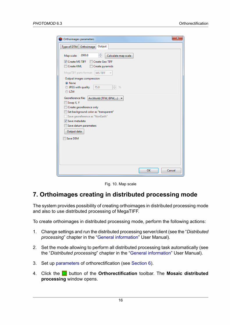
Fig. 10. Map scale
7. Orthoimages creating in distributed processing modeThe system provides possibility of creating orthoimages in distributed processing modeand also to use distributed processing of MegaTIFF.
To create orthoimages in distributed processing mode, perform the following actions:
1. Change settings and run the distributed processing server/client (see the “Distributedprocessing” chapter in the “General information” User Manual).
2. Set the mode allowing to perform all distributed processing task automatically (seethe “Distributed processing” chapter in the “General information” User Manual).
3. Set up parameters of orthorectification (see Section 6).
4. Click the button of the Orthorectification toolbar. The Mosaic distributedprocessing window opens.
16
OrthorectificationPHOTOMOD 6.3

Fig. 11. Mosaic’s distributed processing parameters
5. Define Target folder for output orthoimage.
In case of network processing path mast have \\Server\Share\Folder format.
6. The Number of sheets displays in the window. Set the Number of tasks for pro-cessing based on one kernel for one task.
7. Setup the following parameters:
• Overwrite existing images – allows to rewrite previously created orthoimagessheets;
• Delete temporary project if success – allows to remove the folder with tempor-ary project if success; Is used by default.
8. Set path to a temporary folder for a distributed processing project.
9. Click OK. Distributed processing tasks are created and the system shows amessageabout number of created tasks.
To create orthoimages in distributed processing of MegaTIFFmode, perform the followingactions:
1. Change settings and run the distributed processing server/client (see the “Distributedprocessing” chapter in the “General information” User Manual).
2. Set the mode allowing to perform all distributed processing task automatically (seethe “Distributed processing” chapter in the “General information” User Manual).
3. Set up parameters of orthorectification (see Section 6).
17
OrthorectificationPHOTOMOD 6.3

4. Click the button of the Orthorectification toolbar. The Distributed processingwindow opens.
Fig. 12. Mosaic’s distributed processing of MegaTIFF paramters
The total Number of sheets and Number of MegaTIFF fragments are displaysin the window.
5. Set the number of fragments per task.
It is recommended to estimate number of tasks based on network capacity and speed ofhard drives.
6. Define path for temporary files of distributed processing.
7. Define Target folder for output orthoimages.
In case of network processing path mast have \\Server\Share\Folder format.
8. [optional] To rewrite previously created orthoimages sheets, set on the Overwriteexisting checkbox.
9. Click OK. Distributed processing tasks are created and the system shows amessageabout number of created tasks.
8. Accuracy controlThe system allows to perform accuracy control of orthoimages creation.
Visual displaying of residuals vectors is used for that. Residuals vector on point is adifference of the same point position, calculated from different images for used DEM.
18
OrthorectificationPHOTOMOD 6.3

To display residuals on a block scheme, click the button of the Orthorectificationtoolbar. The Display options and Triangulation points windows open. Residuals aredisplayed in a 2D-window considering to a specified parameters.
Fig. 13. Parameters of triangulation points display
The Display options window contains the toolbar with buttons used to perform thefollowing operations:
• – allows to display list of symbols of point on a block scheme (see the “Block ad-justment” User Manual);
• – allows to set on/off the filter of triangulation points display;
• – allows to set filter of triangulation points display (see the “Block adjustment”User Manual).
In the Mode field is displayed chosen mode of block scheme, It depends on active 2D-window – Block scheme or Image.
Triangulation points are not displayed in the stereopair 2D-window.
The Point display settings section allows to setup the following parameters:
• The Show method of points:
○ symbols – points are displayed by selected symbols;
○ points – point size is specified in pixels.
• Show names the following points in 2D-window:
○ All points;
19
OrthorectificationPHOTOMOD 6.3

○ Selected points;
○ Don’t show points names on a block scheme.
The View error scale section allows to define scale of residuals on a block scheme.Zoom of scale – size of residual vector is equal to a scheme scale. At that vectors arezoom in/out during zooming in/out of block scheme.
Error vector creates in regard to a point’s position on each image with point’s coordinates.
The Displacement vectors section allows to choose what quantity of vectors for whattype of points are displayed on a block scheme:
• Maximal from all images – maximal error vector for each point displays;
• From selected images – all error vectors for points on selected image display;
• From all images – all error vectors for all points display.
Fig. 14. The “Triangulation points” window
Table 2. Toolbar of the “Triangulation points” window
FunctionButtonsallows to set on/off the filter of triangulation points displayallows to setup the filter of triangulation points displayallows to display all/selected points in the tableis used to search for an image by name (part of name)allows to display GC/tie points with initial coordinates (see the “Aerial triangulation”User Manual);allows to set the percent of trim image edges during orthorectificationallows to display triangulation points with coordinates obtained after adjustmentallows to display only errors
20
OrthorectificationPHOTOMOD 6.3
For refreshing data in the list and on a block scheme about project state after changesthe Refresh button is used.
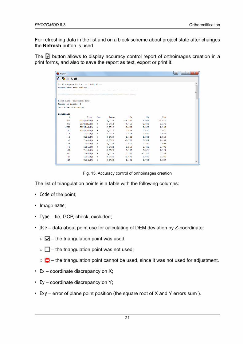
The button allows to display accuracy control report of orthoimages creation in aprint forms, and also to save the report as text, export or print it.
Fig. 15. Accuracy control of orthoimages creation
The list of triangulation points is a table with the following columns:
• Code of the point;
• Image name;
• Type – tie, GCP, check, excluded;
• Use – data about point use for calculating of DEM deviation by Z-coordinate:
○ – the triangulation point was used;
○ – the triangulation point was not used;
○ – the triangulation point cannot be used, since it was not used for adjustment.
• Ex – coordinate discrepancy on X;
• Ey – coordinate discrepancy on Y;
• Exy – error of plane point position (the square root of X and Y errors sum ).
21
OrthorectificationPHOTOMOD 6.3

• Image – name of image for which is calculated error value on selected point.
In the status bar is displayed theRMS value andmaximum error (Max) as points positionand coordinate discrepancy on X and Y.
The Triangulation pointswindow is synchronized with 2D-window: when point selectingin 2D-window it is also selects in the table.
Double-click on point’s name in the table allows to open the Points measurementmodule for edit point’s position.
22
OrthorectificationPHOTOMOD 6.3