User Manual EKI-1334 - ProSoft · EKI-1334 User Manual iv Safety Instructions 1. Read these safety...
72
User Manual EKI-1334
Transcript of User Manual EKI-1334 - ProSoft · EKI-1334 User Manual iv Safety Instructions 1. Read these safety...

User Manual
EKI-1334

CopyrightThe documentation and the software included with this product are copyrighted 2015by Advantech Co., Ltd. All rights are reserved. Advantech Co., Ltd. reserves the rightto make improvements in the products described in this manual at any time withoutnotice. No part of this manual may be reproduced, copied, translated or transmittedin any form or by any means without the prior written permission of Advantech Co.,Ltd. Information provided in this manual is intended to be accurate and reliable. How-ever, Advantech Co., Ltd. assumes no responsibility for its use, nor for any infringe-ments of the rights of third parties, which may result from its use.
AcknowledgementsIntel and Pentium are trademarks of Intel Corporation.
Microsoft Windows and MS-DOS are registered trademarks of Microsoft Corp.
All other product names or trademarks are properties of their respective owners.
Product Warranty (5 years)Advantech warrants to you, the original purchaser, that each of its products will befree from defects in materials and workmanship for five years from the date of pur-chase.
This warranty does not apply to any products which have been repaired or altered bypersons other than repair personnel authorized by Advantech, or which have beensubject to misuse, abuse, accident or improper installation. Advantech assumes noliability under the terms of this warranty as a consequence of such events.
Because of Advantech’s high quality-control standards and rigorous testing, most ofour customers never need to use our repair service. If an Advantech product is defec-tive, it will be repaired or replaced at no charge during the warranty period. For out-of-warranty repairs, you will be billed according to the cost of replacement materials,service time and freight. Please consult your dealer for more details.
If you think you have a defective product, follow these steps:
1. Collect all the information about the problem encountered. (For example, CPU speed, Advantech products used, other hardware and software used, etc.) Note anything abnormal and list any onscreen messages you get when the problem occurs.
2. Call your dealer and describe the problem. Please have your manual, product, and any helpful information readily available.
3. If your product is diagnosed as defective, obtain an RMA (return merchandize authorization) number from your dealer. This allows us to process your return more quickly.
4. Carefully pack the defective product, a fully-completed Repair and Replacement Order Card and a photocopy proof of purchase date (such as your sales receipt) in a shippable container. A product returned without proof of the purchase date is not eligible for warranty service.
5. Write the RMA number visibly on the outside of the package and ship it prepaid to your dealer.
Part No. Edition 1
Printed in Taiwan October 2015
EKI-1334 User Manual ii

Declaration of Conformity
CE
This product has passed the CE test for environmental specifications. Test conditionsfor passing included the equipment being operated within an industrial enclosure. Inorder to protect the product from being damaged by ESD (Electrostatic Discharge)and EMI leakage, we strongly recommend the use of CE-compliant industrial enclo-sure products.
Technical Support and Assistance1. Visit the Advantech web site at http:support.advantech.com.cn where you can
find the latest information about the product.2. Contact your distributor, sales representative, or Advantech's customer service
center for technical support if you need additional assistance. Please have the following information ready before you call:– Product name and serial number– Description of your peripheral attachments– Description of your software (operating system, version, application software,
etc.)– A complete description of the problem– The exact wording of any error messages
Document FeedbackTo assist us in making improvements to this manual, we would welcome commentsand constructive criticism. Please send all such - in writing to: [email protected].
iii EKI-1334 User Manual

Safety Instructions1. Read these safety instructions carefully.2. Keep this User Manual for later reference.3. Disconnect this equipment from any AC outlet before cleaning. Use a damp
cloth. Do not use liquid or spray detergents for cleaning.4. For plug-in equipment, the power outlet socket must be located near the equip-
ment and must be easily accessible.5. Keep this equipment away from humidity.6. Put this equipment on a reliable surface during installation. Dropping it or letting
it fall may cause damage.7. The openings on the enclosure are for air convection. Protect the equipment
from overheating. DO NOT COVER THE OPENINGS.8. Make sure the voltage of the power source is correct before connecting the
equipment to the power outlet.9. Position the power cord so that people cannot step on it. Do not place anything
over the power cord.10. All cautions and warnings on the equipment should be noted.11. If the equipment is not used for a long time, disconnect it from the power source
to avoid damage by transient overvoltage.12. Never pour any liquid into an opening. This may cause fire or electrical shock.13. Never open the equipment. For safety reasons, the equipment should be
opened only by qualified service personnel.14. If one of the following situations arises, get the equipment checked by service
personnel:– The power cord or plug is damaged.– Liquid has penetrated into the equipment.– The equipment has been exposed to moisture.– The equipment does not work well, or you cannot get it to work according to
the user's manual.– The equipment has been dropped and damaged.– The equipment has obvious signs of breakage.
15. DO NOT LEAVE THIS EQUIPMENT IN AN ENVIRONMENT WHERE THE STORAGE TEMPERATURE MAY GO BELOW -40° C (-40° F) OR ABOVE 80° C (140° F). THIS COULD DAMAGE THE EQUIPMENT. THE EQUIPMENT SHOULD BE IN A CONTROLLED ENVIRONMENT.
16. CAUTION: DANGER OF EXPLOSION IF BATTERY IS INCORRECTLY REPLACED. REPLACE ONLY WITH THE SAME OR EQUIVALENT TYPE RECOMMENDED BY THE MANUFACTURER, DISCARD USED BATTERIES ACCORDING TO THE MANUFACTURER'S INSTRUCTIONS.
17. The sound pressure level at the operator's position according to IEC 704-1:1982 is no more than 70 dB (A).
DISCLAIMER: This set of instructions is given according to IEC 704-1. Advantechdisclaims all responsibility for the accuracy of any statements contained herein.
EKI-1334 User Manual iv

Safety Precaution - Static ElectricityFollow these simple precautions to protect yourself from harm and the products fromdamage.
To avoid electrical shock, always disconnect the power from your PC chassis before you work on it. Don't touch any components on the CPU card or other cards while the PC is on.
Disconnect power before making any configuration changes. The sudden rush of power as you connect a jumper or install a card may damage sensitive elec-tronic components.
v EKI-1334 User Manual

EKI-1334 User Manual vi

Contents
Chapter 1 Overview...............................................11.1 Introduction ............................................................................................... 21.2 Package Checklist..................................................................................... 31.3 Product Features....................................................................................... 4
1.3.1 Interfaces ...................................................................................... 41.3.2 Functions ...................................................................................... 41.3.3 Environmental Limits..................................................................... 51.3.4 Power Requirements .................................................................... 51.3.5 Physical Characteristics................................................................ 51.3.6 Advanced Industrial Characteristics.............................................. 51.3.7 Warranty ....................................................................................... 5
Chapter 2 Hardware Installation ..........................72.1 Typical Application .................................................................................... 82.2 Panel Layout ............................................................................................. 82.3 Quick Connection to Internet..................................................................... 9
2.3.1 Insert SIM Card............................................................................. 92.3.2 Antenna Installation ...................................................................... 92.3.3 Power Supply................................................................................ 92.3.4 Connect......................................................................................... 92.3.5 Build Connection between EKI-1334 and PC ............................. 102.3.6 Start to configure your EKI-1334 (Optional)................................ 122.3.7 Connect EKI-1334 with Internet .................................................. 14
2.4 Quick IPSec VPN Configuration.............................................................. 152.5 Reset to Factory Defaults........................................................................ 18
2.5.1 Hardware Approach .................................................................... 182.5.2 Web Approach ............................................................................ 19
Chapter 3 Advanced Configuration...................213.1 Configuration on Web ............................................................................. 22
3.1.1 Preparation ................................................................................. 223.1.2 System........................................................................................ 243.1.3 Network....................................................................................... 293.1.4 Service ........................................................................................ 363.1.5 Firewall........................................................................................ 403.1.6 QoS............................................................................................. 433.1.7 VPN............................................................................................. 443.1.8 Tools ........................................................................................... 533.1.9 Status.......................................................................................... 54
3.2 CLI Configuration .................................................................................... 573.2.1 CLI Operation.............................................................................. 573.2.2 CLI command.............................................................................. 59
Appendix A FAQ .....................................................61A.1 FAQ......................................................................................................... 62A.2 Support.................................................................................................... 63
vii EKI-1334 User Manual

EKI-1334 User Manual viii

Chapter 1
1 OverviewSections include:Introduction
Package Checklist
Features & Specifications
Product Models

1.1 IntroductionEKI-1334 are M2M wireless routers that integrate 3G network and virtual privatenetwork (VPN) technologies. The products meet fundamental needs of fieldcommunication in industry, support international commercial UMTS (HSPA+) andGPRS network.
The design of the EKI-1334 fully incorporated the requirements of industrial users,adopted multi-level software detection mechanism. Multiple VPN protocol ensuressecurity in data transmission, preventing malicious access and tampering of data.The humanized WEB configuration interface is easy for customer to use. It alsosupports connection to multiple network devices, enabling multi service processing.
The EKI-1334 are the ideal choice for industrial usage, having low powerconsumption, wide working temperature range from -20° C to 70° C, small size andlight weight that is easy for application in harsh, narrow industrial environment.
Important Safety Information
This product is not intended for use in the following circumstances
Area(s) where radio transmission equipment (such as cell phone) are not per-mitted.
Hospitals, health care facilities and area(s) where cell phones are restricted by law.
Gas stations, fuel storage and places where chemical are stored. Chemical plants or places with potential explosion hazard. Any metal surface that may weaken the radio signal level.
RF safety distance
For GPRS router, the compliance boundary distance is r=0.26 m for GSM 900 MHz and r=0.13 m for DCS 1800 MHz.
For HSUPA router, the compliance boundary distance is r=0.26 m for GSM 900 MHz and r=0.13 m for DCS 1800 MHz, r=.0.094 for WCDMA 900 MHz, r=0.063 for WCDMA 2100 MHz.
Warning
This is a class A product. In a domestic environment this product may cause radiointerference in which case the user may be required to take adequate measures.
WEEE Notice
The Directive on Waste Electrical and Electronic Equipment (WEEE), which enteredinto force as European law on 13th February 2003, resulted in a major change in thetreatment of electrical equipment at end-of-life.
The purpose of this Directive is, as a first priority, the prevention of WEEE, and inaddition, to promote the reuse, recycling and other forms of recovery of such wastesso as to reduce disposal.
The WEEE logo (shown at the left) on the product or on its box indicates that thisproduct must not be disposed of or dumped with your other household waste. Youare liable to dispose of all your electronic or electrical waste equipment by relocatingover to the specified collection point for recycling of such hazardous waste. Isolatedcollection and proper recovery of your electronic and electrical waste equipment atthe time of disposal will allow us to help conserving natural resources. Moreover,
EKI-1334 User Manual 2

Chapter 1
Overview
proper recycling of the electronic and electrical waste equipment will ensure safety ofhuman health and environment.
For more information about electronic and electrical waste equipment disposal,recovery, and collection points, please contact your local city centre, household wastedisposal service, shop from where you purchased the equipment, or manufacturer ofthe equipment.
1.2 Package ChecklistWe put each EKI-1334 cellular router in a box with standard accessories. Additionally,there’re optional accessories can be ordered. When you receive our package, pleasecheck carefully, and if there’re items missing or appearing to be damaged, pleasecontact with your Advantech sales representative.
Items in package include:
Standard Accessories:
Accessories Description
EKI-1334 Cellular Router 1
Cable 1 Cross line, CAT-5,1.5M
Antenna 3 m Cellular Antenna
3 EKI-1334 User Manual

1.3 Product Features
1.3.1 InterfacesWAN
Cellular WAN:– Band Options: GSM/GPRS/EDGE: 850/900/1800/1900 MHz– UMTS /HSPA/HSPA+: 850/900/1900/2100 MHz
Ethernet WAN:– Ethernet: 10/100 Mbps, RJ45 connector, Auto MDI/MDIX– Magnetic Isolation Protection: 1.5 KV built-in
LAN
Number of Ports: 3 Ethernet: 10/100 Mbps, RJ45 connector, Auto MDI/MDIX Magnetic Isolation Protection: 1.5 KV built-in
DMZ
Number of Ports: 1 Ethernet: 10/100 Mbps, RJ45 connector, Auto MDI/MDIX Magnetic Isolation Protection: 1.5 KV built-in
Serial
Serial Type: RS232 Data bit: 5/6/7/8 Stop bit: 1/2 Check bit: N/O/D Baud rate: 3,200 bit/s ~ 115, 200 bit/s
SIM Interface
SIM Control: 3 V
1.3.2 Functions PPP:
– Support VPDN/APN, fast access to virtual private dial-up network (VPDN) provided by mobile operator, ensure high-security data transmission.
– Support CHAP/PAP/MS-CHAP/MS-CHAP V2 authorization – Support Connection Detection, auto-recovery, auto-link, ensure reliable com-
munication. – Support On-demand connection, SMS Activity
Dynamic IP: Support DHCP, applied as Server/Client Dynamic DNS:
– Support Dynamic DNS-IP Binding – Provide DDNS analyze to help access dynamic data center
Flux Management: Support rate limiting, Firewall Function:
– Package filtering – Port Mapping
EKI-1334 User Manual 4

Chapter 1
Overview
– Virtual Address Mapping – DMZ zone – MAC addresses binding.
Route function: Support Static Routing Table VPN: IPSec/SSL VPN, L2TP/PPTP VPN, GRE Link Backup:
– VRRP: Support VRRP protocols, realizing immediate link backup DNS Forwarding: Support DNS Forwarding, support DNS record Network tools: Support Ping, Trace Route and Telnet
1.3.3 Environmental Limits Operating Temperature: -20 to 70° C (-4 to 158° F) Operating Humidity: 5 to 95% RH Storage Temperature: -40 to 85° C (-40 to 167° F)
1.3.4 Power Requirements Power Inputs: 1 terminal block, including power jack and serial Input Voltage: 9 ~ 26 VDC
1.3.5 Physical Characteristics Housing: Steel, providing IP30 protection Dimensions (mm):
Back Side View Front View
1.3.6 Advanced Industrial Characteristics Physical Characteristics: Shell: Metal, IP30
1.3.7 Warranty Warranty Period: 5 year II
5 EKI-1334 User Manual

EKI-1334 User Manual 6

Chapter 2
2 Hardware InstallationSections include:Typical Application
Panel Layout
Quick Connect to Internet
Quick IPSec VPN Configuration
Reset to Factory Defaults

2.1 Typical ApplicationEKI-1334 can be used to connect your device (with RS232/Ethernet Interface) toInternet via GPRS/ 3G cellular network. Meanwhile, to ensure the security andaccess, EKI-1334 support VPN, enabling remote access and secure data transmis-sion through Internet.
2.2 Panel Layout
The Reset bottom, SIM card slot and power supply are on above panel.
Description of LED
Legend: On-- Off-- Blink--
Power on Start to run firmware Begin dial to Internet
Connect to internet Upgrading firmware Restore factory default
EKI-1334 User Manual 8

Chapter 2
Hardw
areInstallation
Signal Status LED Description
----- Signal: 1-9 (poor signal level, router cannot work, please check the antenna and local signal level)
------ Signal: 10-19 (Router can work under this signal level)
------ Signal: 20-31 (Perfect signal level)
2.3 Quick Connection to Internet
2.3.1 Insert SIM CardOpen EKI-1334 SIM/UIM card case at the bottom, insert the SIM card and close thecase.
2.3.2 Antenna InstallationAfter install the EKI-1334, connect the interface of enhanced antenna to the interfaceof skin antenna and screw tightly. Put the amplifier of enhanced antenna to where itcan receive the signal well.
2.3.3 Power SupplyConnect EKI-1334 to power supply with the power supply cord in the package,observe whether the Power LED on the panel of EKI-1334 goes on. If not, pleasecontact Advantech for technical support.
You can start to configure EKI-1334 after the Power LED turns on.
2.3.4 Connect Link EKI-1334 with PC:
1. Using a cable to link EKI-1334 with a PC;2. After the connection, you can see one LED of RJ45 Interface turns green and
the other flashes.
Caution! Position and angle of the antenna may influence the quality of signal.
9 EKI-1334 User Manual

2.3.5 Build Connection between EKI-1334 and PCEKI-1334 Router can auto-distribute IP address for PC. Please set the PC to auto-matically obtain IP address via DHCP. (Based on Windows Operation System):
1. Open “Control Panel”, double click “Network Connections” icon, and enter “Net-work Connections” Screen.
2. Double click “Local Area Connection”, enter “Local Area Connection Status” screen:
3. Click “Properties”, enter “Local Area Connection Properties” screen
EKI-1334 User Manual 10

Chapter 2
Hardw
areInstallation
Choose “Internet Protocol (TCP/IP)”, click “properties” button, ensure your PC canobtain IP and DNS address automatically. (Or you can set your PC in the subnet:192.168.2.0/24, for example, set IP: 192.168.2.10, Net Mask: 255.255.255.0, DefaultGateway: 192.168.2.1)
Click “OK”, EKI-1334 will allocate an IP address: 192.168.2.x, and a gateway:192.168.2.1(the default address of EKI-1334).
After configure TCP/IP protocols, you can use ping command to check whether thelink between PC and Router is built correctly. Below is an example to execute Pingcommand under Windows XP:
Ping 192.168.2.1
If the screen shows:
11 EKI-1334 User Manual

Then the PC and EKI-1334 are correctly connected. Else if it shows:
The connection is not built, you need to check step by step starting from Section2.3.4.
2.3.6 Start to configure your EKI-1334 (Optional)After you have finished the former steps, you can configure the EKI-1334:
1. Open IE browser, input the default IP address of the Router: http://192.168.2.1, you can see the login page as below:
Input “username” (default: adm) and the “password” (default: 123456), then click“login” to enter the operation screen.
2. Change the IP configuration:
Caution! After updating the configuration, please click “apply” to activate your configuration.
EKI-1334 User Manual 12

Chapter 2
Hardw
areInstallation
If you want to set your own IP of EKI-1334, please follow the instructions below:
Click “Network”=>“LAN”, change the IP address to 192.168.1.254:
3. Click “Apply”, then you will see:
Now the IP address of EKI-1334 has been reset, and in order to enter the configura-tion page, you need to set your PC in the same subnet as EKI-1334, for example:192.168.1.10/24 then input the updated IP address (192.168.1.254) in your IEBrowser.
13 EKI-1334 User Manual

2.3.7 Connect EKI-1334 with InternetFollow the configuration steps below to enable EKI-1334 to connect to the internet.
1. Click “Network”=>“Dialup”, enter dialup configuration interface:
2. Please check the APN, Dialup Number, Username and Password: Dialup Number, Username and Password are provided by local mobile operator. The following examples show parameters provided by China Mobile, Vodafone. Please contact with local operator for details.1: China Mobile
APN: CMNET
Phone Number: *99#
User Name: web
Password: web
2: Vodafone
APN: internet
Phone Number: *99#
User Name: web
Password: web
EKI-1334 User Manual 14

Chapter 2
Hardw
areInstallation
3. After correctly configuring, EKI-1334 can now access Internet. Open IE Browser, input www.google.com, you should see the Google home page:
2.4 Quick IPSec VPN ConfigurationIf you need to build a VPN tunnel to access to your remote PLC through Internet oryou need to ensure security of the data transmission, here’s a quick configurationguide of IPSec for EKI-1334 .
Connect PC with Router to enter router configuration interface, select “VPN” =>“IPSec setting”:
Enable NAT-Traversal (NATT): select enable.
Keep alive time interval of NATT: set the “Keep alive time interval of NATT”, default is60 seconds.
Enable Compression: select enable.
Please change the parameters according to actual situation.
Click “Apply” to complete the configuration.
15 EKI-1334 User Manual

1. Select “VPN”=> “IPSec Tunnels” to check or modify parameters of IPSec Tun-nels.
2. Click “Add” to add a new IPSec Tunnel:
Basic Parameters: basic parameters of IPSec tunnel.
Tunnel Name: name IPSec tunnel, the default is IPSec_tunnel_1.
Destination Address: set to VPN server IP/domain, e.g.: the domain provided by GJJis gjj-ovdp.3322.org.
Startup Modes: select Auto Activated.
Negotiation Mode: optional between Main Mode and Aggressive Mode. Generally,select Main Mode.
IPSec Protocols: optional among ESP, AH. Generally, select ESP.
IPSec Mode: optional between Tunnel Mode and Transport Mode. Generally, selectTunnel Mode.
Tunnel Type: optional among Host-Host, Host-Subnet, Subnet-Host and Subnet-Subnet.
Local Subnet: IPSec local subnet protected. E.g.: 172.16.16.0.
Local Net Mask: IPSec local Net Mask protected. E.g.: 255.255.255.252.
Remote Subnet: IPSec remote subnet protected. E.g.: 172.16.0.0.
Remote Net Mask: IPSec remote Net Mask protected. E.g.: 255.240.0.0.
EKI-1334 User Manual 16

Chapter 2
Hardw
areInstallation
Phase 1 Parameters: configuration parameters during Phase 1 of IPSec negoti-ation.
IKE Policy: optional between 3DES-MD5-96 and AES-MD5-96, suggest selecting3DES-MD5-96.
IKE Lifetime: the default is 86400 seconds.
Local ID Type: optional among FQDN, USERFQDN, IP address, suggest selecting IPaddress.
Remote ID Type: optional among FQDN, USERFQDN, IP address, suggest selectingIP address.
Authentication Type: optional between Shared Key and Certificate, generally chooseShared Key.
Key: set IPSec VPN negotiating key.
Phase 2 Parameters: configuration parameters during Phase 2 of IPSec negoti-ation.
IPSec Policy: optional between 3DES-MD5-96 and AES-MD5-96, suggest selecting3DES-MD5-96.
IPSec Lifetime: the default is 3600 seconds.
Perfect Forward Encryption: Optional among None, GROUP1, GROUP2 andGROUP5. This parameter should match with the server, generally, select “None”.
Click “Save” to finish adding IPSec Tunnel:
You can click “Show Detail Status” to observe the specific connection details, or click“Add” to add a new tunnel.
Now you have successfully built a high-security IPSec tunnel.
And the PC in IPSec client subnet can get access to the server’s subnet.
Open command in your PC, then ping a PC in the server’s subnet:
17 EKI-1334 User Manual

2.5 Reset to Factory Defaults
2.5.1 Hardware Approach
Legend: On-- Off-- Blink--
1. Press and hold RESET button while turning on EKI-1334:
2. When you see ERROR LED turns on (about 10 seconds after power on), release the RESET button:
3. After a few seconds, the ERROR LED will turn off, now press RESET button again:
EKI-1334 User Manual 18

Chapter 2
Hardw
areInstallation
4. Then you will see ERROR and STATUS LED blink, which means reset to factory defaults succeed!
Factory default settings:
IP: 192.168.2.1
Net Mask: 255.255.255.0
Serial parameter: 19200-8-N-1
2.5.2 Web Approach1. Login the web interface of EKI-1334 , select “System”-->”Config Management”:
2. Click “Restore default configuration” to Reset EKI-1334.
19 EKI-1334 User Manual

EKI-1334 User Manual 20

Chapter 3
3 Advanced ConfigurationSections include:Configuration on Web
CLI Configuration

3.1 Configuration on WebEKI-1334 must be correctly configured before use. This chapter will show you how toconfigure EKI-1334 via Web interface.
3.1.1 Preparation1. First, connect your devices to EKI-1334 with a cable or a HUB (switch), then set
the IP of PC and EKI-1334 in the same subnet, for example: Set PC IP to 192.168.2.50, net mask: 255.255.255.0, gateway (default IP of EKI-1334: 192.168.2.1):
EKI-1334 User Manual 22

Chapter 3
Advanced
Configuration
2. Open IE browser, input the IP address of EKI-1334: http://192.168.2.1 (default IP of EKI-1334).Then you’ll see the Login Window pop up, you need to login as Administrator. Input the username and password (default: adm/123456).
3. Click “Login” to enter configure interface:
23 EKI-1334 User Manual

3.1.2 SystemSystem settings include the 9 parts: Basic Setup, Time, Serial Port, Admin Access,System Log, Config Management, Update, Reboot and Logout.
1. Basic Setup
2. Time
Parameters Name Description Default Example
Language Choose language of configuration web Chinese English
Router Name Set name of EKI-1334 Router My Router
Host Name Name the device/PC linked with EKI-1334 Router My Router
Name Description Default
Router Time Display router time 2000-01-01 8:00:00
PC TimeDisplay PC time (or the time of device linked with router)
Time Zone Set time zone Custom
Custom TZ string Set the string of time zone of Router CST-8
Auto Update Time Time Update Interval Disabled
NTP Time Servers (after enable the Auto Update Time)
Setting for NTP Time server. (Three at the most)
pool.ntp.org
EKI-1334 User Manual 24

Chapter 3
Advanced
Configuration
3. Serial Port
4. Admin Access
Name Description Default
Baud Rate Serial baud rate 19200
Data Bit Serial data bits 8
Parity Set parity bit of serial data. None
Stop Bit Set stop bit of serial data. 1
Hardware Flow Control Enable Hardware Flow Control Disable
Software Flow Control Enable Software Flow Control Disable
25 EKI-1334 User Manual

5. System Log
Name Description Default
Username/Password
Username Username for configuration web login adm
Old PasswordTo change the password, you need to input the old one
123456
New Password Input new password
Confirm New Password
Input the new password again
Management
HTTP/HTTPS/TELNET/SSHD/Console
Enable Select to enable Enable
Service Type HTTP/HTTPS/TELNET/SSHD/Console 80/443/23/22/Blank
Local AccessEnable—allow manage Router by LAN(e.g.: HTTP)Disable—forbid manage Router by LAN.
Enable
Remote Access
Enable—allow to manage EKI-1334 by WAN. (e.g.: HTTP)Disable—forbid to manage EKI-1334 by WAN. (e.g.: HTTP)
Enable
Allowed Access from WAN (Optional)
Set the range of allowed IP address for WAN (HTTP/HTTPS/TELNET/SSHD)
Control services server can be set at this time, for example 192.168.2.1/30 or 192.168.2.1-192.168.2.10
DescriptionDescribe the parameters of management (non-influence to EKI-1334 )
Other Parameters
Log TimeoutSet the Log Timeout, configuration web will be dis-connected after timeout
500 seconds
Name Description Default
Log to Remote System
Enable remote log server Disable
IP address/Port (UDP)
Set the IP and Port of remote log server Port: 514
Log to Console Enable remote log server Disable
EKI-1334 User Manual 26

Chapter 3
Advanced
Configuration
6. Config Management
7. System Upgrade
Name Description
Router Configuration Import/Backup configuration file
Restore default configu-ration
Click to reset EKI-1334 (to enable RESET, you need to reboot EKI-1334)
Network Provider (ISP)Used to configure the APN, username, password and other param-eters of major operators
27 EKI-1334 User Manual

To upgrade the system, click “System”=>”System upgrade” to enter update page,then follow the steps below:
Click “Browse”, choose the upgrade file;
Click “update”, and then click “sure” to begin update, the window will show as below.
Upgrade firmware succeed, and click “reboot” to restart EKI-1334 .
8. RebootIf you need to reboot system, please click ”System”=>”Reboot”, then click ”OK” torestart system.
9. LogoutIf you need to logout system, click “System”=>”Logout”, and then click “OK”.
EKI-1334 User Manual 28

Chapter 3
Advanced
Configuration
3.1.3 NetworkNetwork settings include Dialup, LAN, DNS, DDNS, Static Route, and etc.
1. Dialup
29 EKI-1334 User Manual

Name Description Default
Enable Enable PPP dialup Enable
Time Schedule Set time for online and offline ALL
SHARED
Enabled—device linked with Router Can access to internet.Disable—device Can NOT access to internet via Router.
Enable
ISPSelect local ISP, if not listed here, please select ”Customer”
Customer
Network Select Type Choose mobile network typeHSDPA (or GPRS)
APN
APN parameters provided by Local ISP, you can set TWO different group of dialup param-eters (APN/Username/Password) and set one as backup
cmnet/uninet
Access Number Dialup parameters provided by Local ISP“*99#”“*99***1#” or #777
Username Dialup parameters provided by Local ISP“GPRS” or ”CDMA”
Password Dialup parameters provided by Local ISP“GPRS” or ”CDMA”
Static IP Enable Static IP if your SIM card can get static IP address
Disable
Connection Mode Optional Always Online, Always Online
Redial IntervalWhen Dial fails, EKI-1334 will redial after the interval
30 seconds
Show Advanced Options Enable configure advanced options Disabled
Initial Commands Used for advanced parameters Blank
Dial Timeout Set dial timeout (IR700 will reboot after timeout) 120 seconds
MTU Set max transmit unit 1500
MRU Set max receive unit 1500
TX Queue Length Set length of transmit queue 3
Enable IP header com-pression
Enable IP header compression Disabled
Use default asyncmap Enable default asyncmap, PPP advanced option Disabled
Using Peer DNS Click Enable to accept the peer DNS Enabled
Link Detection Interval Set Link Detection Interval 30 seconds
Link Detection Max Retries
Set the max retries if link detection failed 3
Debug Enable debug mode Enable
Expert OptionProvide extra PPP parameters, normally user needn’t set this.
Blank
ICMP Detection ServerSet ICMP Detection Server, blank represents none
Blank
ICMP Detection Interval Set ICMP Detection Interval 30 seconds
ICMP Detection TimeoutSet ICMP Detection Timeout (IR700 will reboot if ICMP time out)
5 seconds
ICMP Detection Max Retries
Set the max number of retries if ICMP failed 5
EKI-1334 User Manual 30

Chapter 3
Advanced
Configuration
Dialup----Time Schedule Management:
2. WAN
This page is to set the type of WAN port:
Name Description Default
Name Name the schedule schedule 1
Sunday Blank
Monday Enable
Tuesday Enable
Wednesday Enable
Thursday Enable
Friday Enable
Saturday Blank
Time Range 1 Set Time Range 1 9:00-12:00
Time Range 2 Set Time Range 2 14:00-18:00
Time Range 3 Set Time Range 3 0:00-0:00
Description Describe configuration Blank
Name Description Default
Type
Static IP;Dynamic Address(DHCP);ADSL Dialup(PPPoE);Disabled
Disabled
31 EKI-1334 User Manual

WAN—Static IP
WAN-Dynamic Address (DHCP)
Caution! There can only be one WAN type at one time, enabling one type WAN will disabled another.
Name Description Default
Type Static IP
SHARED
Enabled—the local device linked with Router can get access to internet.Disable—the local device can’t get access to internet via Router.
Enable
MAC Address Set MAC Address
IP Address Set WAN port IP 192.168.1.29
Net Mask Set WAN port Net Mask 255.255.255.0
Gateway Set WAN Gateway 192.168.1.1
MTUSet Max Transmission Unit, optional between default and manual
1500
Multi-IP Settings(can set 8 additional IP address at the most)
IP address Set the additional IP address of LAN Blank
Net Mask Set Net Mask Blank
Description Describe the settings Blank
EKI-1334 User Manual 32

Chapter 3
Advanced
Configuration
WAN --ADSL
Name Description Default
Type Dynamic Address (DHCP)
SHARED
Enabled—the local device linked with Router can get access to internet.Disable—the local device can’t get access to internet via Router.
Enable
MAC Address Set MAC Address
MTUSet Max transmission unit, optional between default and manual
1500
Name Description Default
Type ADSL Dialup (PPPoE)
SHARED
Enabled—the local device linked with Router can get access to internet.Disable—the local device can’t get access to internet via Router.
Enable
MAC Address Set MAC Address
MTUSet Max Transmission Unit, optional between default and manual
1500
ADSL Dialup (PPPoE) Settings
Username Set username for dialing up Blank
Password Set password for dialing up Blank
Static IP Enable Static IP Disabled
IP address Static IP Address Blank
Peer IP Set Peer IP Blank
Connection ModeSet connection mode (Connect on Demand/Always Online/ Manual)
Always Online
Advanced Options
Show advanced options
Enable advanced configuration Disabled
Service Name Name the service Blank
TX Queue Length Set TX Queue Length 3
33 EKI-1334 User Manual

3. LAN
Enable IP head com-pression
Click to enable IP head compression Disabled
User Peer DNS Enable User Peer DNS Disabled
Link Detection Interval Set link detection interval 55 seconds
Link Detection Max Retries
Set link detection max retries 10 (times)
Debug Select to enable debug-mode Disabled
Expert Options Set expert parameters Blank
ICMP Detection Server Set ICMP Detection Server Blank
ICMP Detection Time Set ICMP Detection Time 30
ICMP Detection Time-out
Set ICMP Detection Timeout 3
ICMP Detection Max Reties
Set ICMP Detection Max Reties 3
Name Description Default
MAC Address The MAC address in LAN00:10:A1:86:95:02 (Provided by Advan-tech) , for manufactures
IP Address Set IP Address in LAN192.168.2.1 (If Changed, you need to input the new address for entering the configuration web)
Net Mask Set Net Mask of LAN 255.255.255.0
MTUSet MTU length, optional between Default and Manual
1500
Detection Host
Set Detection Host Address 0.0.0.0
WOL MAC Address
Set the MAC of PC in the LAN of router, for Wakeup Over LAN (WOL) function, you should also set “Networks”à “Dialup” and change dialup mode into “Trigger by SMS”.
Blank
Multi-IP Settings (Support additional 8 IP addresses at the most)
IP Address Set additional IP Address of LAN Blank
Description Description about this IP address Blank
EKI-1334 User Manual 34

Chapter 3
Advanced
Configuration
4. DNS
5. DDNS (Dynamic DNS)
Name Description Default
Primary DNS Set Primary DNS Blank
Secondary DNS Set Secondary DNS Blank
Name Description Default
Current Address Show the current IP address Blank
Service Type Select DDNS Provider Disabled
35 EKI-1334 User Manual

6. Static Route
3.1.4 ServiceService settings include DHCP Service, DNS Forwarding, VRRP and other relatedparameters.
1. DHCP Service
Name Description Default
Service Type DynDNS - Dynamic
URL http://www.dyndns.com/
Username Registered username for DDNS
Password Registered password for DDNS
Hostname Registered hostname for DDNS
Name Description Default
Destination Set IP address of destination Blank
Net Mask Set subnet Mask of destination 255.255.255.0
Gateway Set the gateway of destination Blank
Interface Optional LAN/WAN port access to destination Blank
Description Describe static route Blank
EKI-1334 User Manual 36

Chapter 3
Advanced
Configuration
2. DNS Relay
Name Description Default
Enable DHCP Click to enable DHCP Enable
IP Pool Starting AddressSet the starting IP address of DHCP pool
192.168.2.2
IP Pool Ending AddressSet the ending IP address of DHCP pool
192.168.2.100
LeaseSet the valid time lease of IP address obtained by DHCP
60 minutes
DNS Set DNS Server 192.168.2.1
Windows Name Server (WINS) Set WINS
BlankStatic DHCP (can set 20 des-ignated IP address at the most)
MAC Address
Set the MAC address of a designated IP address
Blank IP address
Set the static IP address 192.168.2.2 Host
Set the hostname Blank
Name Description Default
Enable DNS Relay Click to enable DNS Relay Disabled
Designate IP address<=>DNS couples (20 at the most)
IP Address Set IP address <=> DNS couples Blank
HostSet the name of IP address <=> DNS couples
Blank
Description Describe IP address <=> DNS couples Blank
37 EKI-1334 User Manual

3. VRRP
4. DTU
Name Description Default
VRRP-1 Select to enable VRRP Disable
Group IDSelect group id of routers (range 1-255)
1
PrioritySelect priority for router (range 1—254)
10 (bigger number stands for higher priority)
Advertisement Interval Set ad interval 60 sec
Virtual IP Set Virtual IP Blank
Authentication TypeOptional: None/Password type
None
Virtual MAC Set Virtual MAC Blank
Monitor Set Monitor None
VRRP-II
EKI-1334 User Manual 38

Chapter 3
Advanced
Configuration
5. SMS
Name Description Default
Enable Click to enable DTU Disable
DTU ProtocolSet DTU protocol, Please see more in related Quick Guide
Transparent
Protocol Optional between TCP/UDP UDP
Mode Set DTU as client or server Client
Frame Interval Set Frame Interval 100
Serial Buffer Frames Set Serial Buffer Frames 4
Multi-Server Policy Optional between Parallel/Poll Parallel
Min Reconnect interval Set Min Reconnect interval 15
Max Reconnect interval Set Max Reconnect interval 180
DTU ID Set ID of DTU Blank
Source IP Set Source IP Blank
Multi ServerSet the IP address and Port of server to receive data.
Blank
Name Description Default
Enable Click to enable SMS control Disable
Status QuerySet Status Query SMS, and you can see status of router by send SMS (e.g.: show status).
Reboot Let the router reboot
SMS Access Control
Default PolicyBlock or Accept control SMS from cer-tain Phone
Block
Phone ListInclude phone numbers accepted or blocked to send SMS to router
Note! Before using this function, please make sure you have a SIM card in the EKI-1334 that has SMS function. Otherwise, please contact local mobile operator to get one.
39 EKI-1334 User Manual

SMS you will get in your mobile phone:
Host: (SN);
Uptime: (the uptime of router for this time of reboot);
State: (Online/Offline) (Cellular WAN IP)
3.1.5 FirewallThis page is to configure the firewall parameters.
1. Basic Configuration
2. Filtering
Name Description Default
Default Filter PolicyOptional between Accept /Refused
Accept
Block Anonymous WAN Request (ping)
Click to enable filer ping request
Disable
Filter Multicast Click to enable filter multicast Enable
Defend DoS AttackClick to enable Defend DoS Attack
Enable
Name Description Default
Enable Click to enable filtering Blank
Protocol Optional among TCP/UDP/ICMP All
Source IP address Set Source IP address Blank
Source Port Set Source Port Blank
Destination IP Set destination IP Blank
Destination Port Set destination port Blank
Action Accept/Deny Accept
Log Click to enable login Disable
Description Describe your configuration Blank
EKI-1334 User Manual 40

Chapter 3
Advanced
Configuration
3. Port Mapping
4. Virtual IP Mapping
An internal PC’s IP can match to a virtual IP, and external network can access theinternal PC via this virtual IP address.
Name Description Default
Enable Click Enable Port Mapping Disable
Source To fill with source IP 0.0.0.0/0
Service Port Fill the port of service 8080
Internal Address Set the internal IP for mapping Blank
Internal Port Set the Port mapping to internal 8080
Log Click to enable log about port mapping. Disable
Description Describe meanings of each mapping Blank
Name Description Default
Virtual IP for Router Set Virtual IP for Router Blank
Source IP Range Set range of source IP address Blank
Virtual IP Set virtual IP Blank
Real IP Set real IP Blank
Log Enable logging concerned with virtual IP Disable
Description Describe this configuration Blank
41 EKI-1334 User Manual

5. DMZ (All Port Mapping)
Mapping all the ports and then external PC can get access to all the ports of internaldevice behind EKI-1334.
6. MAC-IP Bundling
When firewall denies all access to the external network, only PC with MAC-IP Bun-dling can access external network
Caution! This function cannot map the admin port of EKI-1334 (e.g.: 80 TCP) to the device’s port.
Name Description Default
Enable DMZ Click to Enable DMZ Disable
DMZ Host Set host IP of DMZ Blank
Source Address Range Set IP address with restrict IP access Blank
Name Description Default
MAC Address Set Bundling Mac address Blank
IP Address Set Bundling IP address 192.168.2.2
Description Describe this configuration Blank
EKI-1334 User Manual 42

Chapter 3
Advanced
Configuration
3.1.6 QoS1. Banwidth Control
2. IP BM Limit
Name Description Default
Enable Click to enable Disable
Outbound Limit Max Bandwidth
Set the limit speed of out- bound bandwidth
100000kbit/s
Inbound Limit Max Bandwidth
Set the limit speed of inbound bandwidth
100000kbit/s
Name Description Default
Enable Click to enable Disable
IP Address Set IP Address Blank
Rate Set Rate 100 kbit/s
Priority Set the Priority Medum
Description Describe this configuration Blank
43 EKI-1334 User Manual

3.1.7 VPNThis page introduces the parameters in EKI-1334 Web.
1. IPSec Settings To build an IPSec VPN Tunnel, you need to first set IPSec properties on this page,then go to IPSec Tunnels to add your VPN:
2. IPSec Tunnels
IPSec Settings
Description: 1. Select to Enable or Disable NATT, normally we need to enable, unless you ensure
there is no NAT routers in the network. 2. Select to enable Compression Mode or Debug
Name Description Default
Enable NAT Transversal (NATT)
Click to enable NATT Enable
Keep alive time interval of NATT
Set live time for NATT 60 sec
Enable Compression Click to enable Enable
Enable Debug Click to enable Disable
Force NATT Click to enable Disable
EKI-1334 User Manual 44

Chapter 3
Advanced
Configuration
Click “Add” and enter the configuration page:
Name Description Default
Show Advanced OptionsClick to enable advanced options
Disable
Basic Parameters
Tunnel Name To name the tunnel IPSec_tunnel_1
Destination AddressSet the destination address of IPSec VPN Server
Blank
Startup ModeAuto Activate/Trigged by Data/Passive/Manually Activated
Enable
Negotiation ModeOptional: Main Mode orAggressive Mode
Main Mode
45 EKI-1334 User Manual

IPSec Mode(Enable Advanced options)
Optional: ESP or AH ESP
IPSec Mode(Enable Advanced options)
Optional: Tunnel Mode or Transport Mode
Tunnel Mode
Tunnel Type
Optional: Host——Host, Host——Subnet, Subnet——Host, Subnet——Subnet
Subnet——Subnet Mode
Local SubnetSet IPSec Local Protected Sub-net
192.168.2.1
Local Subnet Net MaskSet IPSec Local Protected Sub-net Net Mask
255.255.255.0
Remote Subnet AddressSet IPSec Remote Protected Subnet
Blank
Remote Subnet Net MaskSet IPSec Remote Protected Subnet Net Mask
255.255.255.0
Phase 1 Parameters
IKE PolicyOptional: 3DES-MD5-96 or AES-MD5-96
3DES-MD5-96
IKE Lifetime Set IKE? Lifetime 86400 sec
Local ID TypeOptional: FQDN, USERFQDN, or IP Address
IP Address
Local ID (Only for FQDN and USERFQDN)
Set the ID according to ID type Blank
Remote ID Type Optional: FQDN, USERFQDN, or IP Address
IP Address
Remote ID (Only for FQDN and USERFQDN)
Set the ID according to ID type Blank
Authentication TypeOptional: Shared Key or Certifi-cate
Shared Key
Key (While choosing Shared Key Authentica-tion Type)
Set IPSec VPN Negotiation Key Blank
Phase 2 Parameters
IPSec PolicyOptional: 3DES-MD5-96 or AES-MD5-96
3DES-MD5-96
IPSec Lifetime Set IPSec Lifetime 3600sec
Perfect Forward Secrecy (PFS)
Optional: Disable, GROUP1, GROUP2, GROUP5
Disable ((Enable Advanced options)
Link Detection Parameters (Enable Advanced options)
DPD Time Interval Set DPD Time Interval 60sec
DPD Timeout Set DPD Timeout 180sec
ICMP Detection Server Set ICMP Detection Server Blank
ICMP Detection Local IP Set ICMP Detection Local IP
ICMP Detection Interval Set ICMP Detection Interval 30sec
ICMP Detection Timeout Set ICMP Detection Interval 5sec
ICMP Detection Max Retries
Set ICMP Detection Max Retries
3
EKI-1334 User Manual 46

Chapter 3
Advanced
Configuration
3. GRE Tunnels
4. L2TP Clients
GRE Tunnels
Name Description Default
Enable Click Enable Enable
Tunnel Name Set GRE Tunnel Name tun0
Local Virtual IP Set Local Virtual IP 0.0.0.0
Remote Address Set Remote Address 0.0.0.0
Remote Virtual IP Set Remote Virtual IP 0.0.0.0
Remote Subnet Address Set Remote Subnet Address 0.0.0.0
Remote Subnet Net Mask Set Remote Subnet Net Mask 255.255.255.0
Key Set Tunnel Key Blank
NAT Click Enable NAT Function Disable
Description Add Description Blank
47 EKI-1334 User Manual
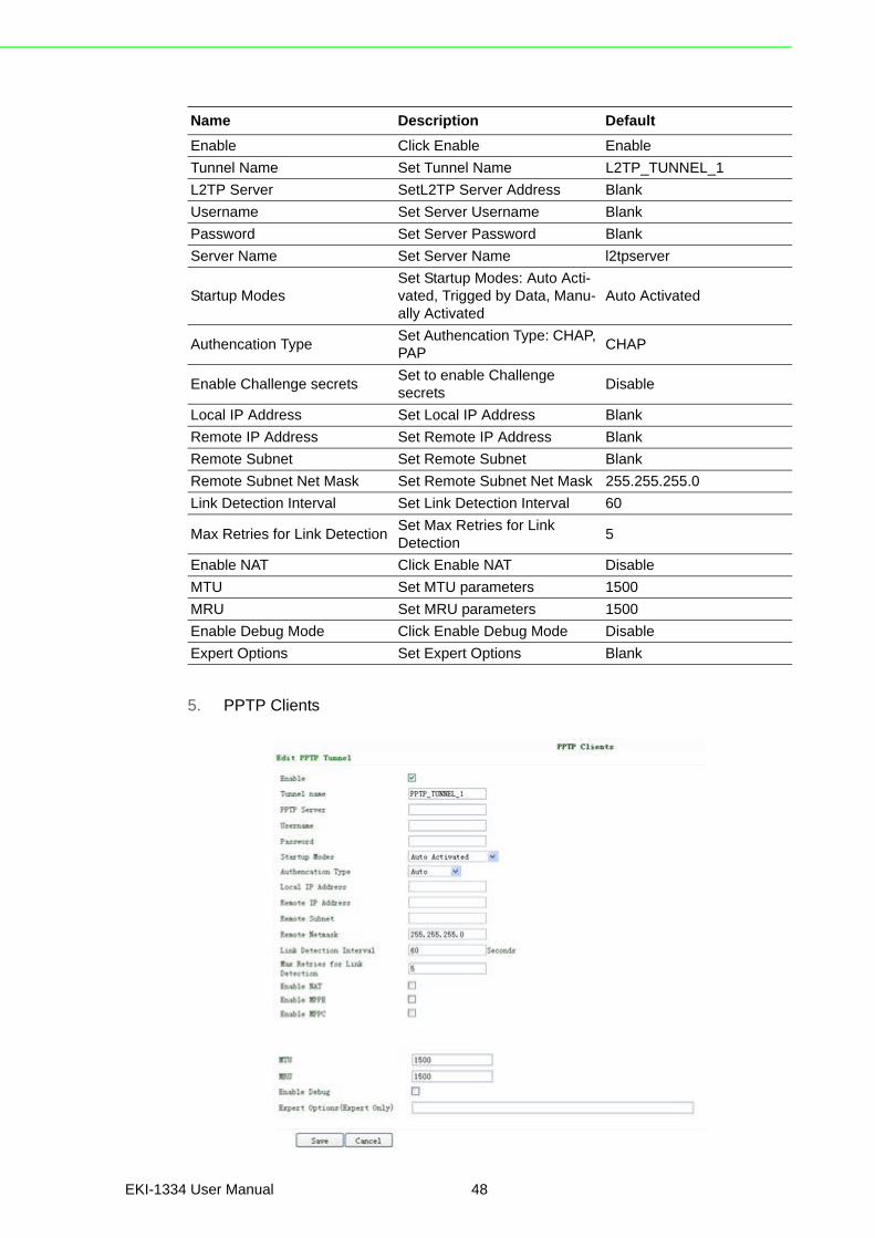
5. PPTP Clients
Name Description Default
Enable Click Enable Enable
Tunnel Name Set Tunnel Name L2TP_TUNNEL_1
L2TP Server SetL2TP Server Address Blank
Username Set Server Username Blank
Password Set Server Password Blank
Server Name Set Server Name l2tpserver
Startup ModesSet Startup Modes: Auto Acti-vated, Trigged by Data, Manu-ally Activated
Auto Activated
Authencation TypeSet Authencation Type: CHAP, PAP
CHAP
Enable Challenge secretsSet to enable Challenge secrets
Disable
Local IP Address Set Local IP Address Blank
Remote IP Address Set Remote IP Address Blank
Remote Subnet Set Remote Subnet Blank
Remote Subnet Net Mask Set Remote Subnet Net Mask 255.255.255.0
Link Detection Interval Set Link Detection Interval 60
Max Retries for Link DetectionSet Max Retries for Link Detection
5
Enable NAT Click Enable NAT Disable
MTU Set MTU parameters 1500
MRU Set MRU parameters 1500
Enable Debug Mode Click Enable Debug Mode Disable
Expert Options Set Expert Options Blank
EKI-1334 User Manual 48

Chapter 3
Advanced
Configuration
6. OpenVPN Settings
Name Description Default
Enable Click Enable Enable
Tunnel Name Set Tunnel Name PPTP_TUNNEL_1
PPTP Server Set PPTP Server Address Blank
Username Set Server Username Blank
Password Set Server’s Password Blank
Startup Mode:Set Startup Modes: Auto Acti-vated, Trigged by Data, Manu-ally Activated
Auto Activated
Authencation TypeSet Authencation Type: CHAP, PAP, MS-CHAPv1, MS-CHAPv2
Auto
Local IP Address Set Local IP Address Blank
Remote IP Address Set Remote IP Address Blank
Remote Subnet Set Remote Subnet Blank
Remote Subnet Net Mask Set Remote Subnet Net Mask 255.255.255.0
Link Detection Interval Set Link Detection Interval 60
Max Retries for Link DetectionSet Max Retries for Link Detection
5
Enable NAT Click Enable NAT Blank
Enable MPPE Click Enable MPPE Blank
Enable MPPC Click Enable MPPC Blank
MTU Set MTU parameters 1500
MRU Set MRU parameters 1500
Enable Debug Mode Click Enable Debug Mode Blank
Expert Options For Advantech R&D only Blank
49 EKI-1334 User Manual

This page is to configure the OpenVPN settings, including Tunnel Name, Work Mode,Protocol, Port No. and other items.
Name Description
Tunnel name default
Enable Enable this configuration
Mode Client or Server
Protocol UDP or TCP
Port Import or Export Certificate (CRL)
OPEN VPN Server OPEN VPN Server’s IP or DNS
Authencation Type
1. None ----- for host to host connection (not available when 700 as server)
2. Pre-shared Key ----- for host to host connection (not available when 700 as server)
3. User/Password ----- For multi users to access CA needed: Client: root CA (ca.crt) Server: root CA (ca.crt), public key (pub.crt), private key (pri.key)4. X.509 Cert (multi-client) ----- CA mode for multi users to
access CA needed: Client: root CA (ca.crt), public key (pub.crt), private key (pri.key) Server: root CA (ca.crt), public key (pub.crt), private key (pri.key)5. X.509 Cert -----CA mode for host to host tunnel CA needed: Client: root CA (ca.crt), public key (pub.crt), private key (pri.key) Server: root CA (ca.crt), public key (pub.crt), private key (pri.key)6. User+X.509 mode------username + password + CA cer-
tificate CA needed: Client: root CA (ca.crt), public key (pub.crt), private key (pri.key) Server: root CA (ca.crt), public key (pub.crt), private key (pri.key)
Pre-shared Key Set shared key or TLS-AUTH static password
Remote Subnet, Remote Net mask
Set the static route of the router, always towards the subnet of its peer
Link Detection Interval, Link Detection Timeout
Always use default
Renegotiate Interval Always use default
EKI-1334 User Manual 50

Chapter 3
Advanced
Configuration
7. OpenVPN Advanced Settings
This page is to configure the OpenVPN advanced settings.
Enable NAT Set NAT mode, meanwhile it will disable route mode
Enable MPPE Enable MPPE, always set in server
Enable LZO Enable LZO compression
Encryption Algorithms Set encryption algorithms, must match with the server
MTU, Max Fragment Size Always use default
Name Description
Enable Client-to-Client Enable client access to other clients
Client Management
Tunnel Name Tunnel Name of the Client
Username/Common NameUsername (using Username/password mode) or Common Name in CA (CA mode)
Local Static Route The client subnet
Remote Static Route The server subnet
Caution! CA can only be produced by customer’s PC; EKI-1334 cannot produceCA.
51 EKI-1334 User Manual

8. Certificate Management of OpenVPN Settings
Name Description Default
Enable SCEP (Simple Certificate Enrollment Protocol)
Click Enable
Certificate Protected Key Set Certificate Protected Key Blank
Certificate Protected Key ConfirmConfirm Certificate Protected Key
Blank
Import/Export CA Certificate Import or Export (CA) Certifi-cate
Blank
Import/Export Certificate (CRL) Import or Export Certificate (CRL)
Blank
Import/Export Public Key Certificate Import or Export Public Key Certificate
Blank
Import/Export Private Key Certificate Import or Export Private Certifi-cate
Blank
EKI-1334 User Manual 52

Chapter 3
Advanced
Configuration
3.1.8 ToolsTools contain PING Detection, Route Trace, Link Speed Test and etc.
1. PING
2. Trace Route
Name Description Default
Host Destination for PING Blank
Ping Count Set PING Counts 4 times
Packet Size Set PING Packet Size 32 Bytes
Expert Options Advanced parameters Blank
Name Description Default
Host Destination for Trace Route Blank
Max Hops Set Max Hops 20
Time Out Set Time Out 3 sec
Protocol Optional: ICMP/UDP UDP
Expert Options Advanced parameters Blank
53 EKI-1334 User Manual

3. Link Speed Test
Test link speed via unload or download
3.1.9 StatusStatus contains System, Modem, WLAN, Network Connections, Route Table, DeviceList and Log.
1. System Status
This page shows the status of system, including Name, Model Type, Current Versionand etc.
2. Modem Status
This page shows the status of Modem, including signal level.
EKI-1334 User Manual 54
Chapter 3
Advanced
Configuration
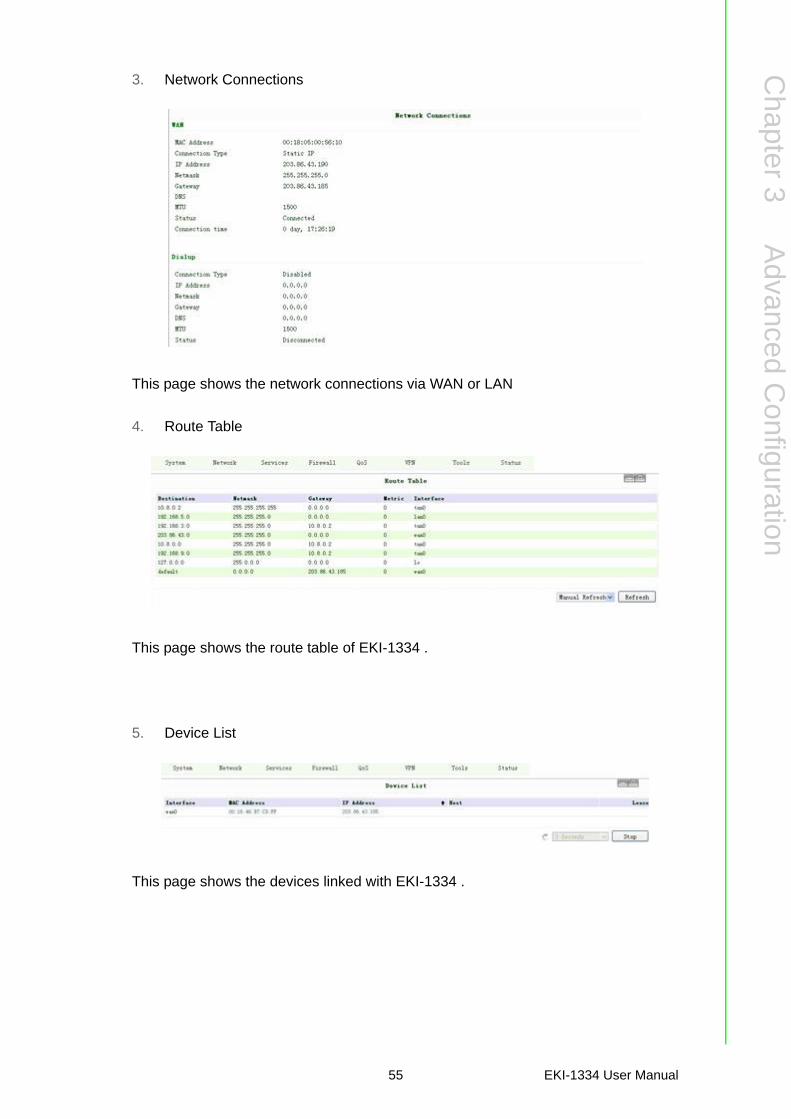
3. Network Connections
This page shows the network connections via WAN or LAN
4. Route Table
This page shows the route table of EKI-1334 .
5. Device List
This page shows the devices linked with EKI-1334 .
55 EKI-1334 User Manual

6. Log
This page shows the log of system, including download log file.
Under certain situation when there’re problems that can’t be diagnosed at themoment, you’ll be asked to provide the diagnose log to Advantech engineers.
.
EKI-1334 User Manual 56

Chapter 3
Advanced
Configuration
3.2 CLI ConfigurationThis chapter will show you how to configure via CLI.
3.2.1 CLI Operation1. Input telnet LAN IP to login CLI configuration. For example:
2. After connection is succeed, input username and password of EKI-1334 . The default username/password is adm/123456.
Caution! Password will not be showed.
57 EKI-1334 User Manual

3. Login to User Mode
This screenshot is the config-view of IR700.
4. Enter privileged mode, password is 123456
EKI-1334 User Manual 58

Chapter 3
Advanced
Configuration
5. Login to privileged mode successfully
6. Enter configured mode, then you could configure parameters you want to set up.
3.2.2 CLI commandConfigure username and password
Enable serial function
Configure serial port parameters, like baudrate, parity, stop bit and so on.
Enable advanced options of dialup
Configure ICMP server
Configure LAN IP
59 EKI-1334 User Manual

Enable DHCP function
Configure DHCP IP pool: 192.168.2.10-192.168.2.20
Enable HTTP function
Configure HTTP service port
Enable HTTP local access
Enable HTTP remote access
Check device ID
After configuration, please don’t forget to commit and reboot router!
EKI-1334 User Manual 60

Appendix A
A FAQ
A.1 FAQ1. EKI-1334 is powered on, but can`t access Internet through it?Please check?
Whether the EKI-1334 is inserted with a SIM card. Whether the SIM card is enabled with data service, whether the service of the
SIM card is suspended because of an overdue charge. Whether the dialup parameters, e.g. APN, dialup number, username and pass-
word are correctly configured. Whether the IP Address of your computer is the same subnet with EKI-1334 and
the gateway address is EKI-1334 LAN address.
2. EKI-1334 is powered on, have a ping to detect EKI-1334 from your PC and find packet loss?
Please check if the network crossover cable is in good condition.
3. Forget the setting after revising IP address and can`t configure EKI-1334 r?Method 1: connect EKI-1334 with serial cable, configure it through console port.
Method 2: within 5 seconds after EKI-1334 is powered on, press and hold theRestore button until the ERROR LED flashes, then release the button and theERROR LED should goes off, press and hold the button again until the ERROR LEDblinks 6 times, the EKI-1334 is now restored to factory default settings. You may con-figure it now.
4. After EKI-1334 is powered on, it frequently auto restarts. Why does this hap-pen?
Please check:
Whether the module works normally. Whether the EKI-1334 is inserted with a SIM card. Whether the SIM card is enabled with data service, whether the service of the
SIM card is suspended because of an overdue charge. Whether the dialup parameters, e.g. APN, dialup number, username and pass-
word are correctly configured. Whether the signal is normal. Whether the power supply voltage is normal.
5. Why does upgrading the firmware of my EKI-1334 always fail?Please check:
When upgrading locally, check if the local PC and EKI-1334 are in the same net-work segment.
When upgrading remotely, please first make sure the EKI-1334 can access Internet.
6. After EKI-1334 establishes VPN with the VPN server, your PC under EKI-1334 can connect to the server, but the center can`t connect to your PC under EKI-1334?
Please make sure the firewall of your computer is disabled.
7. After EKI-1334 establishes VPN with the VPN server, Your PC can`t connect to the server?
EKI-1334 User Manual 62

Appendix A
FA
Q
Please make sure “Shared Connection” on “Network=>WAN” or “Network=>Dialup”is enabled in the configuration of EKI-1334.
8. EKI-1334 is powered on, but the Power LED is not on? Check if the protective tube is burn out. Check the power supply voltage range and if the positive and negative elec-
trodes are correctly connected.
9. EKI-1334 is powered on, but the Network LED is not on when connected to PC? When the PC and EKI-1334 are connected with a network cable, please check
whether a network crossover cable is used. Check if the network cable is in good condition. Please set the network card of the PC to 10/100M and full duplex.
10. EKI-1334 is powered on, when connected with PC, the Network LED is normal but can`t have a ping detection to the EKI-1334?
Check if the IP Address of the PC and EKI-1334 are in the same subnet and the gateway address is EKI-1334 LAN address.
11. EKI-1334 is powered on, but can`t configure through the web interface? Whether the IP Address of your computer is the same subnet with EKI-1334 and
the gateway address is EKI-1334 LAN address. Check the firewall settings of the PC used to configure EKI-1334, whether this
function is shielded by the firewall.
12. The EKI-1334 dialup always fails, I can`t find out why?Please restore EKI-1334 to factory default settings and configure the parametersagain.
13. How to restore EKI-1334 to factory default settings? Press and hold the Restore button, power on EKI-1334; Release the button until after the STATUS LED flashes and the ERROR LED is
on; After the button is released, the ERROR LED will go off, within 30s press and
hold the Restore button again until the ERROR LED flashes; Release the button, the system is now successfully restored to factory default
settings.
A.2 SupportIn case you have problems with the installation and use, please address them to usby e-mail:
63 EKI-1334 User Manual

www.advantech.com.cnPlease verify specifications before quoting. This guide is intended for referencepurposes only.All product specifications are subject to change without notice.No part of this publication may be reproduced in any form or by any means,electronic, photocopying, recording or otherwise, without prior written permis-sion of the publisher.All brand and product names are trademarks or registered trademarks of theirrespective companies.© Advantech Co., Ltd. 2015


![User Manual EKI-7700 Series...4 EKI-7700 Series User Manual 1.2.2 MAC Address Table [no] protected Admin EXEC Use "protected" command to protect port. Protected port is only allowed](https://static.fdocuments.us/doc/165x107/606ebb1ab3b2f6208b4942b4/user-manual-eki-7700-series-4-eki-7700-series-user-manual-122-mac-address.jpg)