User Manual EKI-122X Series - Advantechadvdownload.advantech.com/productfile/Downloadfile2... ·...
67
User Manual EKI-122X Series 1/2/4-port Modbus Gateway
Transcript of User Manual EKI-122X Series - Advantechadvdownload.advantech.com/productfile/Downloadfile2... ·...

User Manual
EKI-122X Series
1/2/4-port Modbus Gateway

CopyrightThe documentation and the software included with this product are copyrighted 2016by Advantech Co., Ltd. All rights are reserved. Advantech Co., Ltd. reserves the rightto make improvements in the products described in this manual at any time withoutnotice. No part of this manual may be reproduced, copied, translated or transmittedin any form or by any means without the prior written permission of Advantech Co.,Ltd. Information provided in this manual is intended to be accurate and reliable. How-ever, Advantech Co., Ltd. assumes no responsibility for its use, nor for any infringe-ments of the rights of third parties, which may result from its use.
AcknowledgementsIntel and Pentium are trademarks of Intel Corporation.
Microsoft Windows and MS-DOS are registered trademarks of Microsoft Corp.
All other product names or trademarks are properties of their respective owners.
Product Warranty (5 years)Advantech warrants to you, the original purchaser, that each of its products will befree from defects in materials and workmanship for five years from the date of pur-chase.
This warranty does not apply to any products which have been repaired or altered bypersons other than repair personnel authorized by Advantech, or which have beensubject to misuse, abuse, accident or improper installation. Advantech assumes noliability under the terms of this warranty as a consequence of such events.
Because of Advantech’s high quality-control standards and rigorous testing, most ofour customers never need to use our repair service. If an Advantech product is defec-tive, it will be repaired or replaced at no charge during the warranty period. For out of-warranty repairs, you will be billed according to the cost of replacement materials,service time and freight. Please consult your dealer for more details.
If you think you have a defective product, follow these steps:
1. Collect all the information about the problem encountered. (For example, CPU speed, Advantech products used, other hardware and software used, etc.) Note anything abnormal and list any on screen messages you get when the problem occurs.
2. Call your dealer and describe the problem. Please have your manual, product, and any helpful information readily available.
3. If your product is diagnosed as defective, obtain an RMA (return merchandize authorization) number from your dealer. This allows us to process your return more quickly.
4. Carefully pack the defective product, a fully-completed Repair and Replacement Order Card and a photocopy proof of purchase date (such as your sales receipt) in a shippable container. A product returned without proof of the purchase date is not eligible for warranty service.
5. Write the RMA number visibly on the outside of the package and ship it prepaid to your dealer.
Part No. 2009122101 Edition 1
Printed in Taiwan October 2016
EKI-122X Series User Manual ii

Declaration of Conformity
CE
This product has passed the CE test for environmental specifications when shieldedcables are used for external wiring. We recommend the use of shielded cables. Thiskind of cable is available from Advantech. Please contact your local supplier forordering information.
This product has passed the CE test for environmental specifications. Test conditionsfor passing included the equipment being operated within an industrial enclosure. Inorder to protect the product from being damaged by ESD (Electrostatic Discharge)and EMI leakage, we strongly recommend the use of CE-compliant industrial enclo-sure products.
FCC Class A
Note: This equipment has been tested and found to comply with the limits for a ClassA digital device, pursuant to part 15 of the FCC Rules. These limits are designed toprovide reasonable protection against harmful interference when the equipment isoperated in a commercial environment. This equipment generates, uses, and canradiate radio frequency energy and, if not installed and used in accordance with theinstruction manual, may cause harmful interference to radio communications. Opera-tion of this equipment in a residential area is likely to cause harmful interference inwhich case the user will be required to correct the interference at his own expense.
Technical Support and Assistance1. Visit the Advantech web site at www.advantech.com/support where you can find
the latest information about the product.2. Contact your distributor, sales representative, or Advantech's customer service
center for technical support if you need additional assistance. Please have the following information ready before you call:– Product name and serial number– Description of your peripheral attachments– Description of your software (operating system, version, application software,
etc.)– A complete description of the problem– The exact wording of any error messages
iii EKI-122X Series User Manual

Warnings, Cautions and Notes
Document FeedbackTo assist us in making improvements to this manual, we would welcome commentsand constructive criticism. Please send all such - in writing to: [email protected]
Packing ListBefore setting up the system, check that the items listed below are included and ingood condition. If any item does not accord with the table, please contact your dealerimmediately.
1 x EKI-1221 or EKI-1222 or EKI-1224 Modbus Gateway 1 x Terminal Block 1 x Document and software CD 2 x Wall/panel mount kit
Safety Instructions1. Read these safety instructions carefully.2. Keep this User Manual for later reference.3. Disconnect this equipment from any AC outlet before cleaning. Use a damp
cloth. Do not use liquid or spray detergents for cleaning.4. For plug-in equipment, the power outlet socket must be located near the equip-
ment and must be easily accessible.5. Keep this equipment away from humidity.6. Put this equipment on a reliable surface during installation. Dropping it or letting
it fall may cause damage.
Warning! Warnings indicate conditions, which if not observed, can cause personal injury!
Caution! Cautions are included to help you avoid damaging hardware or losing data. e.g.
There is a danger of a new battery exploding if it is incorrectly installed. Do not attempt to recharge, force open, or heat the battery. Replace the battery only with the same or equivalent type recommended by the man-ufacturer. Discard used batteries according to the manufacturer's instructions.
Note! Notes provide optional additional information.
EKI-122X Series User Manual iv

7. The openings on the enclosure are for air convection. Protect the equipment from overheating. DO NOT COVER THE OPENINGS.
8. Make sure the voltage of the power source is correct before connecting the equipment to the power outlet.
9. Position the power cord so that people cannot step on it. Do not place anything over the power cord.
10. All cautions and warnings on the equipment should be noted.11. If the equipment is not used for a long time, disconnect it from the power source
to avoid damage by transient overvoltage.12. Never pour any liquid into an opening. This may cause fire or electrical shock.13. Never open the equipment. For safety reasons, the equipment should be
opened only by qualified service personnel.14. If one of the following situations arises, get the equipment checked by service
personnel:15. The power cord or plug is damaged.16. Liquid has penetrated into the equipment.17. The equipment has been exposed to moisture.18. The equipment does not work well, or you cannot get it to work according to the
user's manual.19. The equipment has been dropped and damaged.20. The equipment has obvious signs of breakage.21. DO NOT LEAVE THIS EQUIPMENT IN AN ENVIRONMENT WHERE THE
STORAGE TEMPERATURE MAY GO BELOW -40°C (-40°F) OR ABOVE 75°C (167°F). THIS COULD DAMAGE THE EQUIPMENT. THE EQUIPMENT SHOULD BE IN A CONTROLLED ENVIRONMENT.
22. CAUTION: DANGER OF EXPLOSION IF BATTERY IS INCORRECTLY REPLACED. REPLACE ONLY WITH THE SAME OR EQUIVALENT TYPE RECOMMENDED BY THE MANUFACTURER, DISCARD USED BATTERIES ACCORDING TO THE MANUFACTURER'S INSTRUCTIONS.
Safety Precaution - Static ElectricityFollow these simple precautions to protect yourself from harm and the products fromdamage.
To avoid electrical shock, always disconnect the power from your PC chassis before you work on it. Don't touch any components on the CPU card or other cards while the PC is on.
Disconnect power before making any configuration changes. The sudden rush of power as you connect a jumper or install a card may damage sensitive elec-tronic components.
v EKI-122X Series User Manual

Contents
Chapter 1 Introduction ......................................... 11.1 Overview ................................................................................................... 21.2 Device Features........................................................................................ 2
Chapter 2 Getting Started .................................... 32.1 Understanding Modbus Gateways............................................................ 4
2.1.1 Protocol Overview......................................................................... 4Figure 2.1 Modbus System Architecture 1 ................................ 5Figure 2.2 Modbus System Architecture 2 ................................ 5
2.1.2 Modbus RTU................................................................................. 52.1.3 Modbus ASCII............................................................................... 52.1.4 Modbus ASCII............................................................................... 6
2.2 Specifications............................................................................................ 62.3 Hardware .................................................................................................. 8
2.3.1 Front View..................................................................................... 8Figure 2.3 Front View ................................................................ 8Figure 2.4 Front View ................................................................ 9Figure 2.5 Front View .............................................................. 10
2.3.2 Rear View ................................................................................... 11Figure 2.6 Rear View............................................................... 11Figure 2.7 Rear View............................................................... 12
2.3.3 Top View..................................................................................... 12Figure 2.8 Top View ................................................................ 12
2.3.4 LED Indicators ............................................................................ 13Figure 2.9 System LED Panel ................................................. 13
2.3.5 Dimensions ................................................................................. 14Figure 2.10 EKI-1221 and EKI-1222 Dimensions...................... 14Figure 2.11 EKI-1224 Dimensions............................................. 15
2.4 Connecting Hardware ............................................................................. 162.4.1 Choosing a Location ................................................................... 16
Figure 2.12 Installing the DIN-Rail Mounting Kit........................ 16Figure 2.13 Removing the DIN-Rail........................................... 17Figure 2.14 Installing Wall Mount Plates ................................... 18Figure 2.15 Wall Mounting Screw Dimensions.......................... 19Figure 2.16 Wall Mount Installation ........................................... 19
2.4.2 Serial Connection ....................................................................... 20Figure 2.17 DB9 Pin Assignment .............................................. 20
2.4.3 Power Connection ...................................................................... 20Figure 2.18 Power Wiring for EKI-122X Series ......................... 21
Chapter 3 Configuration .................................... 223.1 Configuration Utility Overview................................................................. 233.2 Installing the Configuration Utility............................................................ 23
Figure 3.1 InstallShield Wizard 1 of 4...................................... 24Figure 3.2 InstallShield Wizard 2 of 4...................................... 24Figure 3.3 InstallShield Wizard 3 of 4...................................... 25Figure 3.4 InstallShield Wizard 4 of 4...................................... 25
3.3 Menu Bar ................................................................................................ 26Figure 3.5 Configuration Utility Overview ................................ 26
3.4 Quick Tool Bar ........................................................................................ 273.4.1 Utility Settings ............................................................................. 28
EKI-122X Series User Manual vi

Figure 3.7 View > Settings > Main Form Setting ..................... 28Figure 3.8 View > Settings > Device Manager ........................ 29
3.4.2 Discovering Your Device Server ................................................. 30Figure 3.9 Open View of Serial Device Configuration Utility.... 30Figure 3.10 Selecting a Group................................................... 31Figure 3.11 Selecting a Device.................................................. 31Figure 3.12 Viewing Basic Settings ........................................... 31
3.4.3 Network Settings......................................................................... 32Figure 3.13 Utility Overview....................................................... 32Figure 3.14 Network Settings Overview .................................... 33Figure 3.15 Reset Device .......................................................... 34
3.5 Administrator Settings ............................................................................. 353.5.1 Locate the Serial Device Server ................................................. 35
Figure 3.16 Locate the Serial Device Server ............................. 353.5.2 Securing the Serial Device Server .............................................. 36
Figure 3.17 Lock the Serial Device Server ................................ 36Figure 3.18 Enter a Password ................................................... 37Figure 3.19 Reset Device .......................................................... 37Figure 3.20 Unlock the Serial Device Server............................. 38
3.5.3 Restore to Factory Default Settings ............................................ 39Figure 3.21 Restore to Factory Default Settings........................ 39
3.5.4 Resetting the Device................................................................... 39Figure 3.22 Reset Device .......................................................... 40
3.5.5 Add to Favorite............................................................................ 41Figure 3.23 Add to Favorite ....................................................... 41
3.5.6 Update Firmware ........................................................................ 41Figure 3.24 Update Firmware .................................................... 42
Chapter 4 Web Interface .....................................434.1 Overview ................................................................................................. 444.2 Accessing the Web Page ........................................................................ 44
4.2.1 Accessing the Web Page via Configuration Utility ...................... 44Figure 4.1 Accessing the Web Page via Configuration Utility.. 44
4.2.2 Accessing the Web Page via Web Browser................................ 454.3 System .................................................................................................... 45
Figure 4.2 Setting Time Zone .................................................. 454.4 Ethernet Configuration ............................................................................ 46
Figure 4.3 Ethernet Configuration............................................ 464.5 Port Configuration ................................................................................... 47
4.5.1 Basic ........................................................................................... 47Figure 4.4 Port Configuration > Basic...................................... 47
4.5.2 Operation .................................................................................... 48Figure 4.5 Master Mode........................................................... 48Figure 4.6 Slave Mode............................................................. 48Figure 4.7 Port Configuration > Operation............................... 49Figure 4.8 Port Configuration > Operation............................... 49
4.6 Monitor .................................................................................................... 504.6.1 Setting......................................................................................... 50
Figure 4.9 Monitor > Setting .................................................... 504.6.2 Statistic ....................................................................................... 514.6.3 Connected IP .............................................................................. 52
4.7 Auto Warning (Alarm).............................................................................. 524.7.1 Setting......................................................................................... 52
Figure 4.12 Alarm > Setting....................................................... 534.7.2 Event........................................................................................... 54
Figure 4.13 Alarm > Event......................................................... 544.8 Syslogd ................................................................................................... 55
4.8.1 Syslogd Setting ........................................................................... 55
vii EKI-122X Series User Manual

Figure 4.14 Syslogd > Syslogd Setting ..................................... 554.8.2 Syslogd Message ....................................................................... 55
Figure 4.15 Syslogd > Syslogd Message .................................. 554.8.3 Modbus IP Mapping.................................................................... 55
Figure 4.16 Syslogd > Modbus IP Mapping .............................. 554.8.4 Modbus Port Mapping................................................................. 56
Figure 4.17 Syslogd > Modbus Port Mapping ........................... 564.9 Tools ....................................................................................................... 56
4.9.1 Ping............................................................................................. 56Figure 4.18 Tools > Ping ........................................................... 56
4.9.2 Reboot ........................................................................................ 57Figure 4.19 Tools > Reboot....................................................... 57
4.10 Management ........................................................................................... 574.10.1 Log File ....................................................................................... 574.10.2 Change Password ...................................................................... 58
Figure 4.21 Management > Change Password......................... 584.10.3 Export Device Settings ............................................................... 58
Figure 4.22 Management > Export ............................................ 584.10.4 Import Device Settings................................................................ 58
Figure 4.23 Management > Import ............................................ 58
EKI-122X Series User Manual viii

Chapter 1
1Introduction
1.1 OverviewAdvantech’s EKI-1221/EKI-1222/EKI-1224 series of Modbus Gateways (the followingmanual will use EKI-122X series instead of complete model name) are a robust, fea-ture-rich, and cost effective way to integrate Ethernet and Serial Modbus devices.The EKI-122X series provides one, two or four serial ports, two Ethernet ports, a widerange of power inputs, and a compact slim design, making them an ideal solution forconnecting multiple Modbus/ RTU and Modbus/ASCII serial devices to Modbus TCP(Ethernet).
Originally developed for PLCs in industrial automation and manufacturing controlapplications, Modbus is one of the most popular open standard protocols in usetoday. The communication mode can be Modbus RTU/ASCII (Serial) or Modbus TCP(Ethernet). Many industrial devices use Modbus as their communication standard.However, the Ethernet-based Modbus protocol is different from the original serial-based protocols that a Modbus Gateway is needed to be a bridge for integration.
The two Ethernet ports allow the EKI-122X series to establish two separatedEthernet connections to two Ethernet domains or two Ethernet switches in the samedomain. Through a dual Ethernet connection, the EKI-122X series greatly improvesthe device connectivity reliability, increase system stability, and simplify theredundant configuration.
The Modbus/RTU and Modbus/ASCII protocols define how a “master” device pollsone or more “slave” devices and write real-time data over RS-232, RS-422, or RS-485 serial data communication. The EKI-122X series provides a feature that canallow users to select master or slave operation for each serial port. The EKI-122Xseries not only allows Ethernet master can control serial slaves, but also allow serialmasters to control Ethernet or serial slaves. Furthermore, the EKI-122X series canallow both Ethernet and serial slaves to be controlled by both Ethernet and serialmasters.
The EKI-122X series supports various operating modes: RTU Master, RTU Slave,ASCII Master, and ASCII Slave.
1.2 Device Features Provides 2 x 10/100 Mbps Ethernet ports for LAN redundancy Integration of Modbus TCP and Modbus RTU/ASCII networks Supports up to 921.6 kbps, and any baud rate setting Supports up to 16 connections and 32 requests simultaneously Auto searching slave ID over configuration utility Software selectable RS-232/422/485 communication Mounts on DIN-rail and Wall mount Built-in 15 KV ESD protection for all serial signals Automatic RS-485 data flow control Supports surge protection for D.C. power ports with line to line 2 KV, and line to
earth 4 KV; for signal ports with 4 KV. 'I' models support a wide operating temperature 'CI' models support isolation and wide operating temperature
EKI-122X Series User Manual 2

Chapter 2
2Getting Started
2.1 Understanding Modbus GatewaysNetworks have become increasingly vital for industrial automation applications. Manycontrol devices today do not have a network port and can only communicate with adedicated local PC or control panel. Advantech’s revolutionary network-enablingtechnology is now allowing control devices with serial ports to connect to the Ethernetand share networks quickly and cost-effectively. The EKI-122X Series are network-based, Modbus gateways for integrating new and existing Mo bus/RTU and Modbus/ASCII serial devices to newer TCP/IP networked-based devices. Manufacturers, sys-tem integrators, and end users can now take advantage of Modbus gateways to cre-ate networked applications for remote managing and accessing data for their controldevices that wasn’t possible before.
2.1.1 Protocol OverviewOriginally developed for PLCs in industrial automation and manufacturing controlapplication, Modbus has become one of the most popular open standard protocols inuse today. When it comes to planning data communication for open, multi-vendorindustrial control systems, Modbus is the first choice of end-users and integrators.
Although it’s not the most powerful protocol available, its rare simplicity allows notonly rapid implementation, but also remains flexible enough to be applied in virtuallyall industrial situations. The communication mode of Modbus can be ASCII, RTU, orTCP/IP. Modbus gateways are used to support applications such as protocol conver-sion between serial (Modbus/ASCII or Modbus/RTU) and networked (Modbus/TCP)Modbus devices or it can be used to bridge Modbus serial devices over TCP/IP net-work.
The Modbus/RTU and Modbus/ASCII protocols define how a “master” device pollsone or more “slave” devices to read and write real-time data over RS-232, RS-422, orRS-485 serial data communication. The simplicity of Modbus/RTU not only allowsrapid implementation, but can also remain flexible enough to be applied in virtually allindustrial situations.
During Modbus network communication, the protocol determines how each controllerwill know its device address, recognize a message addressed to it, determine thekind of action to be taken, and extract any data or other information contained in themessage. If a reply is required, the controller will construct the reply message andsend it back using Modbus protocol.
The way controllers communicate with each other is by using a master-slave tech-nique, in which only one device (the master) can initiate queries. The other devices(the slaves) respond by supplying the requested data to the master, or by taking theaction requested in the query. Typical master devices include host processors andprogramming panels. Typical slaves include programmable controllers.
It is the master that can address individual slaves and initiate a broadcast messageto all slaves. On the other hand, slaves return a response to queries that areaddressed to them individually. Responses are not returned to broadcast queriesfrom the master.
The Modbus protocol has a definite format for the master’s query, which incorporatesthe device (or broadcast) address, a function code defining the requested action, anydata to be sent, and an error-checking field. The slave’s response message, which isalso constructed using Modbus protocol, contains fields confirming the action taken,any data to be returned, and an error-checking field. If an error occurred in receipt ofthe message, or if the slave is unable to perform the requested action, the slave willconstruct an error message and send it as its response.
EKI-122X Series User Manual 4

The basic system architecture is as below:
Figure 2.1 Modbus System Architecture 1
Figure 2.2 Modbus System Architecture 2
2.1.2 Modbus RTUThe Modbus/RTU protocol defines how a “master” device polls one or more “slave”devices to read and write data in real-time over RS-232, RS-422, or RS-485 serialdata communication.
When using RTU mode, each 8-bit byte in a message contains two 4-bit hexadecimalcharacters. The main advantage of this mode is that its greater character densityallows better data throughput than ASCII mode for the same baud rate. Neverthe-less, each message must be transmitted in continuous stream.
2.1.3 Modbus ASCIIWhen using ASCII mode, each 8-bit byte in a message is sent as two ACSII charac-ters. The primary advantage of this ASCII mode is that it allows time intervals of up toone second to occur between characters without causing an error.
PWR2P-Fail DC12-48V
DC12-48V
PWR1
V2- V2+V1- V1+ 1A@24V
1
2
1
2
P1 P2 Status
Default
EKI - 1222
TxRx
TxRx
Serial P
orts PWR2P-Fail DC12-48V
DC12-48VPWR1
V2- V2+V1- V1+
1A@24V
1
2
1
Default
LANS
erial Ports
Serial P
orts
P1 P2 Status
EKI - 1221
TxRx
Ethernet 1
Ethernet 2
1
2
RS232
(Modbus / Ascll)
(Modbus / RTU)
(Modbus / Ascll)
RS485
(Modbus / RTU) R
S485R / Asc
RTUR
(Modbuus /
(Mo(dbuus /
PC
Host (PC)
EKI 1222
EKI 1221
PLCModbus / TCPMaster Device
o
RTU) 485
RS485
U) RS4A
(Mo((Mo(M
AscAscll)
(Modbus / A/ AA
PWR2P-Fail DC12-48V
DC12-48V
PWR1
V2- V2+V1- V1+ 1A@24V
1
2
1
3
2
4
P1 P2 Status
Default
LAN
Serial PortsEKI - 1224
TxRx
TxRx
TxRx
TxRx
Ethernet 1
RS232/422/485
Ethernet 2
Mode RTU ASCII
Coding System 8-bit binary.Two hexadecimal character co tained in each ASCII character of the message
Hexadecimal.One hexadecimal character co tained in each ASCII character of the message
Bits per Byte 1 start bit,8 data bits,1 bit for even/odd parity; no bit for parity 1 stop bit if parity is used; 2 bits if no parity
1 start bit ,7 data bits,1 bit for even/odd parity; no bit for parity1 stop bit if parity is used; 2 bits if no parity
Error Check CRC LRC
5 EKI-122X Series User Manual
2.1.4 Modbus ASCIIAs a new extension of Modbus/RTU, the Modbus/TCP protocol defines how Modbus/RTU messages are encoded within and transported over TCP/IP-based networks.Modbus/TCP is just as simple to implement and flexible to apply as the original Mod-bus/RTU. The Modbus/TCP protocol is defined by its form of encapsulation for aModbus request or response. That means the Modbus request or response data isencapsulated in TCP frame that has a six-byte header in Modbus/TCP protocol.
Modbus/TCP enables the use of Modbus messaging in an Intranet running the TCP/IP protocols. Modbus/TCP is most commonly used for Ethernet attachment of PLC’sor I/O modules to other simple field buses or I/O networks.
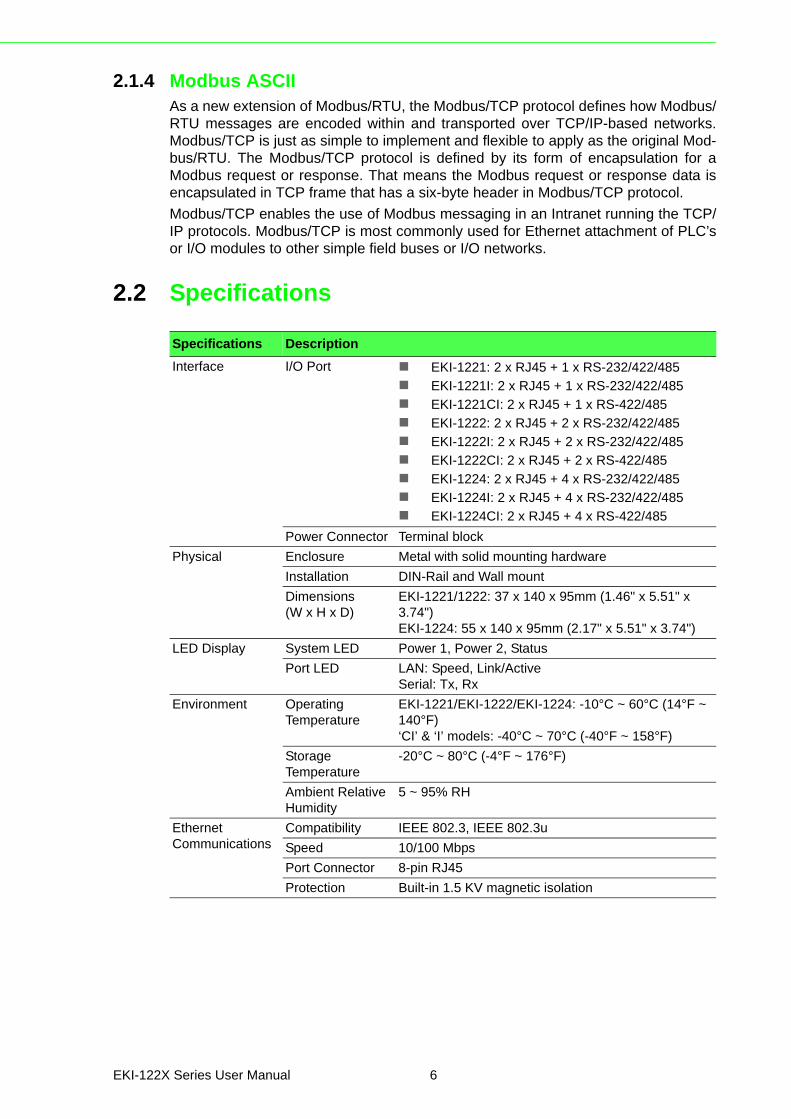
2.2 Specifications
Specifications Description
Interface I/O Port EKI-1221: 2 x RJ45 + 1 x RS-232/422/485
EKI-1221I: 2 x RJ45 + 1 x RS-232/422/485
EKI-1221CI: 2 x RJ45 + 1 x RS-422/485
EKI-1222: 2 x RJ45 + 2 x RS-232/422/485
EKI-1222I: 2 x RJ45 + 2 x RS-232/422/485
EKI-1222CI: 2 x RJ45 + 2 x RS-422/485
EKI-1224: 2 x RJ45 + 4 x RS-232/422/485
EKI-1224I: 2 x RJ45 + 4 x RS-232/422/485
EKI-1224CI: 2 x RJ45 + 4 x RS-422/485
Power Connector Terminal block
Physical Enclosure Metal with solid mounting hardware
Installation DIN-Rail and Wall mount
Dimensions (W x H x D)
EKI-1221/1222: 37 x 140 x 95mm (1.46" x 5.51" x 3.74")EKI-1224: 55 x 140 x 95mm (2.17" x 5.51" x 3.74")
LED Display System LED Power 1, Power 2, Status
Port LED LAN: Speed, Link/ActiveSerial: Tx, Rx
Environment Operating Temperature
EKI-1221/EKI-1222/EKI-1224: -10°C ~ 60°C (14°F ~ 140°F)‘CI’ & ‘I’ models: -40°C ~ 70°C (-40°F ~ 158°F)
Storage Temperature
-20°C ~ 80°C (-4°F ~ 176°F)
Ambient Relative Humidity
5 ~ 95% RH
Ethernet Communications
Compatibility IEEE 802.3, IEEE 802.3u
Speed 10/100 Mbps
Port Connector 8-pin RJ45
Protection Built-in 1.5 KV magnetic isolation
EKI-122X Series User Manual 6

Serial Communications
Port Type RS-232/422/485, software selectable
Port Connector DB9 male
Data Bits 7, 8
Stop Bits 1, 2
Parity None, Odd, Even, Space, Mark
Flow Control XON/XOFF, RTS/CTS, DTR/DSR
Baud Rate 50 bps ~ 921.6 kbps, any baud rate setting
Protection Built-in 15 KV ESD for all signals'CI' models: 2KV Isolation for RS-422/485 signals
Power Power Consumption
EKI-1221: 5.2W
EKI-1222: 5.2W
EKI-1224: 6.3W
Power Input 12 ~ 48VDC, redundant dual inputs
Software OS Support 32-bit/64-bit Windows XP/Vista/7/8/8.1, Windows Server 2003/2008/2008 R2/2012/2012 R2, and Linux
Utility Advantech EKI Device Configuation Utility
Operation Modes Modbus RTU Master/Slave modeModbus ASCII Master/Slave mode
Configuration Windows utility, Web Browser
Management SNMP MIB-II
Regulatory Approvals
EMC CE, FCC Part 15 Subpart B (Class A)
Specifications Description
7 EKI-122X Series User Manual

2.3 Hardware
2.3.1 Front ViewThe following view shows the EKI-1221.
Figure 2.3 Front View
No. Item Description
1 System LED panel See “LED Indicators” on page 13 for further details.
2 Default button Press for at least 10 secs. to rest device to default settings.
3 ETH port RJ45 ports x 2
4 Serial port DB9 pinout, supports 232/422/485
1
1
2
Default
LAN
TxRx
P1 P2 Status
Serial ports
EKI-1221
1
2
3
4
EKI-122X Series User Manual 8

The following view shows the EKI-1222.
Figure 2.4 Front View
No. Item Description
1 System LED panel See “LED Indicators” on page 13 for further details.
2 Default button Press for at least 10 secs. to rest device to default settings.
3 ETH port RJ45 ports x 2
4 Serial port DB9 (pinout) ports x 2, supports 232/422/485
1
1
2
Default
LAN
TxRx
TxRx
P1 P2 Status
Serial ports
EKI-1222
1
2
3
4
9 EKI-122X Series User Manual

The following view shows the EKI-1224.
Figure 2.5 Front View
No. Item Description
1 System LED panel See “LED Indicators” on page 13 for further details.
2 Default button Press for at least 10 secs. to rest device to default settings.
3 ETH port RJ45 ports x 2
4 Serial port DB9 (pinout) ports x 4, supports 232/422/485
1
1
2
3
4
2
Default
LAN
TxRx
TxRx
TxRx
TxRx
P1 P2 Status
Serial ports
EKI-1224
1
2
3
4
EKI-122X Series User Manual 10

2.3.2 Rear ViewThe following view shows the EKI-1221 and EKI-1222.
Figure 2.6 Rear View
No. Item Description
1 DIN-Rail mounting plate
Mounting plate used for the installation to a standard DIN rail
1
11 EKI-122X Series User Manual

The following view shows the EKI-1224.
Figure 2.7 Rear View
2.3.3 Top View
Figure 2.8 Top View
No. Item Description
1 DIN-Rail mounting plate
Mounting plate used for the installation to a standard DIN rail
1
No. Item Description
1 Ground terminal Screw terminal used to ground chassis
2 Terminal block Connect cabling for power and alarm wiring
2 Wall mounting holes Screw holes (top x4, bottom x4) used in the installation of a wall mounting plate
PWR2
P-Fail
DC12-48V PWR1
V2- V2+V1- V1+
1A@24V
1
2
3
EKI-122X Series User Manual 12

2.3.4 LED Indicators
Figure 2.9 System LED Panel
No. LED Name LED Color Description
1 P1 Green Power 1 is on
Off Power 1 is off, or power error condition exists
2 P2 Green Power 2 is on
Off Power 2 is off, or power error condition exists
3 Status Amber The device server has been located by utility’s loca-tion function
Amber, blinking System is ready (1cycle/sec.)
Off System is not working
P1 P2 Status
1 2 3
13 EKI-122X Series User Manual

2.3.5 DimensionsThe following view shows the EKI-1221 and EKI-1222.
Figure 2.10 EKI-1221 and EKI-1222 Dimensions
10495
30.50 40
140
47.05
47.95
36.60
149.80
150
33
15
35
14.90
17.83
EKI-122X Series User Manual 14

The following view shows the EKI-1224.
Figure 2.11 EKI-1224 Dimensions
33
15
35
23.83
14.70
10495
30.50 40
140
47.05
47.95
48.65
149.80
15 EKI-122X Series User Manual

2.4 Connecting Hardware
2.4.1 Choosing a Location
2.4.1.1 DIN Rail MountingThe DIN rail mount option is the quickest installation option. Additionally, it optimizesthe use of rail space.
The metal DIN rail kit is secured to the rear of the serial device server. The devicecan be mounted onto a standard 35mm (1.37”) x 75mm (3”) height DIN rail. Thedevices can be mounted vertically or horizontally. Refer to the following guidelines forfurther information.
Installing the DIN-Rail Mounting Kit
1. Insert the top back of the mounting bracket over the DIN rail.2. Push the bottom of the server towards the DIN rail until it snaps into place.\
Figure 2.12 Installing the DIN-Rail Mounting Kit
Removing the DIN-Rail Mounting Kit
1. Push the server down to free the bottom of the plate from the DIN rail.2. Rotate the bottom of the device towards you and away from the DIN rail.
Note! A corrosion-free mounting rail is advisable.
When installing, make sure to allow for enough space to properly install the cabling.
DIN Rail
EKI-122X Series User Manual 16

3. Once the bottom is clear of the DIN rail, lift the device straight up to unhook it from the DIN rail.
\
Figure 2.13 Removing the DIN-Rail
2.4.1.2 Wall-MountingThe wall mounting option provides better shock and vibration resistance than the DINrail vertical mount.
Before the device can be mounted on a wall, you will need to remove the DIN railplate.
1. Rotate the device to the rear side and locate the DIN mounting plate.2. Remove the screws securing the DIN mounting plate to the rear panel of the
server.3. Remove the DIN mounting plate. Store the DIN mounting plate and provided
screws for later use.4. Align the wall mounting plates on the rear side. The screw holes on the device
and the mounting plates must be aligned, see the following illustration.
DIN Rail
Note! When installing, make sure to allow for enough space to properly install the cabling.
17 EKI-122X Series User Manual
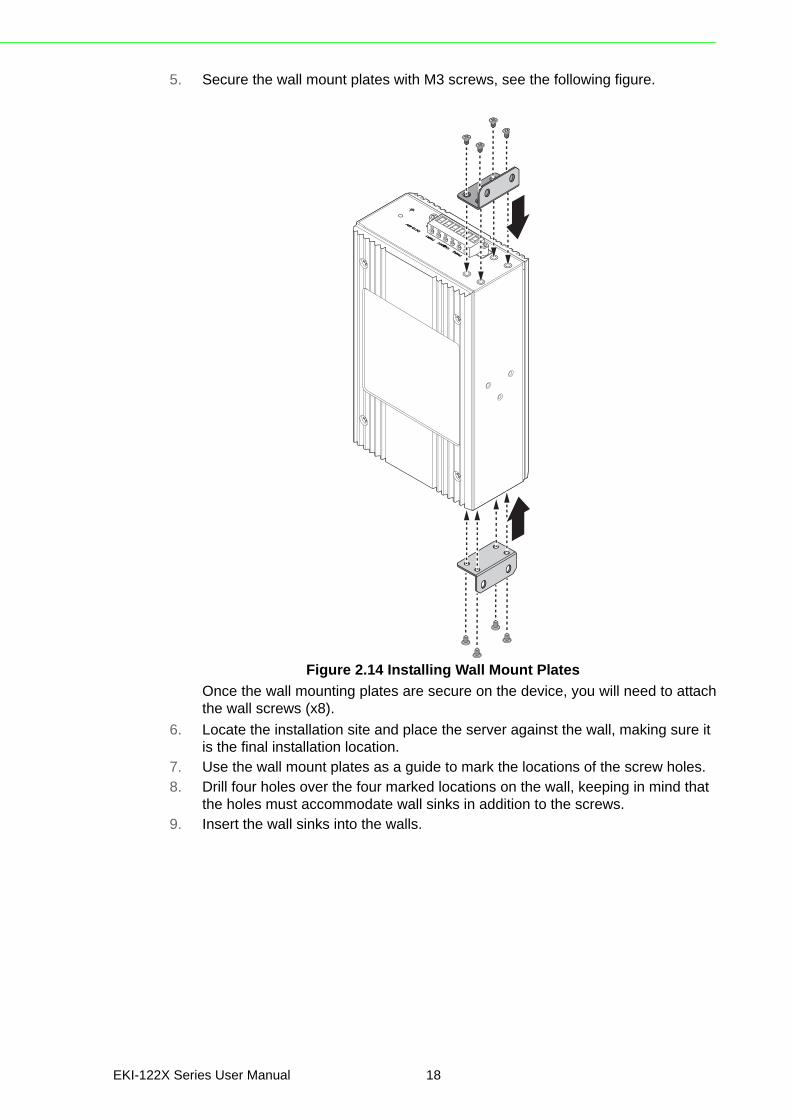
5. Secure the wall mount plates with M3 screws, see the following figure.
Figure 2.14 Installing Wall Mount Plates
Once the wall mounting plates are secure on the device, you will need to attachthe wall screws (x8).
6. Locate the installation site and place the server against the wall, making sure it is the final installation location.
7. Use the wall mount plates as a guide to mark the locations of the screw holes.8. Drill four holes over the four marked locations on the wall, keeping in mind that
the holes must accommodate wall sinks in addition to the screws.9. Insert the wall sinks into the walls.
EKI-122X Series User Manual 18

10. To mount the wall plate, use screws of the size shown in the following illustra-tion.
Figure 2.15 Wall Mounting Screw Dimensions
11. Align the wall mount plate over the screws on the wall.12. Install the wall mount plate on the screws and slide it forward to lock in place,
see the following figure.
Figure 2.16 Wall Mount Installation
13. Once the device is installed on the wall, tighten the screws to secure the device.
Note! Make sure the screws dimensions are suitable for use with the wall mounting plate.
Do not completely tighten the screws into the wall. A final adjust-ment may be needed before fully securing the wall mounting plates on the wall.
8.0 mm
4.0 mm
2
2
1
19 EKI-122X Series User Manual

2.4.2 Serial ConnectionEKI-122X Series provides up to four ports DB9 (male) connectors. RS-232/422/485pin assignments as below:
Figure 2.17 DB9 Pin Assignment
2.4.3 Power Connection
2.4.3.1 Overview
The EKI-122X Series supports dual 12 to 48 VDC power inputs and power-fail relayoutput.
Pin 1 2 3 4 5 6 7 8 9
RS-232 DCD RX TX DTR GND DSR RTS CTS RI
RS-422 TX- TX+ GND RX+ RX-
RS-485 DATA- DATA+ GND
1
96
5
Warning! Power down and disconnect the power cord before servicing or wiring the serial device server.
Caution! Do not disconnect modules or cabling unless the power is first switched off.
The device only supports the voltage outlined in the type plate. Do not use any other power components except those specifically designated for the serial device server.
Caution! Disconnect the power cord before installation or cable wiring.
EKI-122X Series User Manual 20

The following figure illustrates a P-Fail alarm application example. The P-Fail alarmcontacts are visible on the front view of the terminal block.
Figure 2.18 Power Wiring for EKI-122X Series
You can connect an alarm indicator, buzzer or other signaling equipment through therelay output. The relay opens if power input 1 or 2 fails. In a wiring example where anLED is connected to the relay output, the LED would be off in an Open state.
LoadExternal Power
21 EKI-122X Series User Manual

Chapter 3
3Configuration
3.1 Configuration Utility OverviewAdvantech EKI series serial device servers provide an easy-to-use utility to configureyour serial device server through an Ethernet connection. For secure administration,it can also restrict the access rights for configuration to only one host PC. With thissecure function enabled, other PCs will not have permission for configuration. Afterthe installation program on the Advantech IEDG Series Driver Utility CD-ROM is fin-ished, the serial device servers are ready for use and configuration.
Advantech Serial Device Server Configuration Utility is an excellent device servermanagement tool. You can connect and configure the local and remote Advantechserial device servers easily. The utility provides access to the following functions:
Configure the network settings (you can set the IP address, Gateway address, and Subnet mask)
View and set the serial port parameters (configure operating mode, baud rate, serial port settings and operating mode settings)
Perform diagnostic tests (virtual COM port testing, port status list) Perform administrative functions (export and import the serial device server set-
ting, manage access IP, a descriptive name, upgrade firmware)
3.2 Installing the Configuration Utility
1. Insert the Advantech EKI Device Configuration Utility CD-ROM into the CD-ROM drive (whereas E:\ is the drive name of your CD-ROM) on the host PC.
2. Use Windows explorer or the Windows Run command to execute the setup pro-gram, the path for the setup program on the CD-ROM is as follows:E:\EKI_Device_Configuration_Utility_v2.01.exe
3. If there is an existing COM port mapping utility on the host PC, remove it at this time. A system reboot may be necessary before continuing the installation.
Note! Microsoft .NET Framework version 2.0 or greater is required for this application.
23 EKI-122X Series User Manual

4. Once the InstallShield Wizard screen displays, click Next to proceed with the installation.
Figure 3.1 InstallShield Wizard 1 of 4
5. The Software License Agreement displays, press I Agree to continue or Cancel to stop the installation.
Figure 3.2 InstallShield Wizard 2 of 4
EKI-122X Series User Manual 24

The InstallShield continues and a status screen displays. The default installationpath is C:\Program Files\EKI Device Configuration Utility.
Figure 3.3 InstallShield Wizard 3 of 4
6. Once the installation of the package is finished a Configuration Utility Setup screen displays. Click Finish to conclude the process and exit the InstallShield Wizard.
Figure 3.4 InstallShield Wizard 4 of 4
25 EKI-122X Series User Manual

3.3 Menu BarYou can open the Configuration Utility from the Windows Start Menu by clicking Start> All Programs > EKI Device Configuration Utility > EKI Device ConfigurationUtility. The Configuration Utility displays as shown in the following figure.
Figure 3.5 Configuration Utility Overview
No Item Description
1 Menu Bar Displays File, View, Management, Tools and Help.
2 Quick Tool Bar Useful management functions shortcuts.
3 Serial Device Server List Area
Available devices are listed in this area. Devices and COM ports can be organized or grouped in this area.
4 Information Panel Click on the devices or move cursor to the devices, the related information is shown in this area.
5 Status Bar Displays the current time.
6 Configuration Area Click on the item on the Device Server List Area, the configura-tion page displays.
5
4
3
2
6
1
EKI-122X Series User Manual 26

3.4 Quick Tool BarThe Advantech EKI Device Configuration Utility makes use of a Quick Tool Bar menuto allow quick access to the management functions. See the following figure for fur-ther information.
Figure 3.6 Quick Tool Bar Overview
Icon Item Description
Utility Settings Clear to configure the general settings for the Main Form Setting and Device Manager menus. Refer to “Utility Settings” on page 28.
Configuration Wizard Start the software wizard (setup assistant) to lead you through the VCOM configuration process for device server product.
Clear Device List and Search Again
Click to clear listed device servers in the Serial Device Server List Area and initiate a new search.
NOTE: A continuous click of the icon results in the following message: Please do not refresh so fre-quently.
Search Again Click to search for serial device servers on the local LAN.
Add IP Address to Favorite
Click to include the selected IP Address into the Favor-ites list group.
Search for a Range of IP Addresses
Click to begin a range search. Enter the beginning and ending IP addressed to being a search within the string parameters.
Manual Direct Map-ping Virtual COM Port
Click to add a target by selecting the Device Type and inputting the IP address without physically connecting the serial device server to the network.
27 EKI-122X Series User Manual

3.4.1 Utility Settings
3.4.1.1 Main Form SettingClick View > Settings to configure utility settings.
Figure 3.7 View > Settings > Main Form Setting
Item Description
Main Window Settings
Maximum Main Window On Load
Check the box to enable the limiting of main windows on-load to the maximum value.
Log Settings
Show Log Message Win-dow
Check the check box to activate the AdvLogMessage form. The Form Log message displays.
Save Log to File Check the check box to save log to file.
Browse If the Save Log to File option is enabled, click Browse to select a file to save log data.
Language Settings
Interface Language Click the drop-down menu to select an interface language: Tradi-tional Chinese, Simplified Chinese or English.
NOTE: A restart is required for the settings to take effect.
OK Click OK to save and exit the Utility Settings menu.
Cancel Click Cancel to discard the changes.
Apply Click Apply to save the main form settings.
EKI-122X Series User Manual 28

3.4.1.2 Device Manager
Figure 3.8 View > Settings > Device Manager
Item Description
Device Manager
Tree View Grouping Click the drop-down menu to enable or disable grouping.
Show Empty Device Type Node
Check the check box to show empty device type node or not.
Expand New Appended Device Node
Check the check box to expand a new appended device node.
Device Auto Detection
After utility ready, start auto detection after X sec-ond
Enter a value to specify the time to auto detection time (-1 means disable auto detection).
Auto detect devices every X second
Enter a value to specify the time to auto detect devices.
Check device alive every X second
Enter a value to specify the time to check device alive.
Mark device as lost con-tact after retry for X times
Enter a value to specify the time to mark device as lost contact.
Unsigned Hardware Installation
Automatic answer for unsigned hardware instal-lation
Check the check box to enable or disable answer automatically for unsigned hardware installation.
OK Click OK to save and exit the utility setting.
Cancel Click Cancel to discard the changes.
Apply Click Apply to save the utility setting.
29 EKI-122X Series User Manual

3.4.2 Discovering Your Device Server
3.4.2.1 Auto SearchingAdvantech Serial Device Server Configuration Utility will automatically search all theEKI-122X Series device servers on the network and show them on the Serial DeviceServer List Area of the utility. The utility provides an auto-search function to showyour device (s) by simply executing the configuration utility program from the StartMenu.
From here all devices on the same network domain will be searched and displayedon Device Server List Area. You can click on a device name to show the features ofthe specific device.
Click on the “+” before the model name, and the utility will expand the tree structureto show the individual device name. Click on the “-” before the model name, and theutility will collapse the tree structure.
Figure 3.9 Open View of Serial Device Configuration Utility
In the previous figure, the EKI serial device server is listed as EKI-1222-BE-2AD3AC.
Select the device in this sub-tree. The first tab on the Configuration Area shows thesummary of “Basic Information” included device type, version, and name, “Ethernet
Note! When you run the configuration utility for the first time, the default device name is obtained from the serial device’s MAC identification number. The name can be altered through the configuration utility.
EKI-122X Series User Manual 30

Information”, and “Serial Port Information”. In the serial port information frame, it dis-plays the operation mode, status and connected host IP.
Figure 3.10 Selecting a Group
Click on the “+” before the device name, and the utility will expand the interfaces onthis device server.
Figure 3.11 Selecting a Device
Click on each item to enter the configuration page to change the setting. The configu-ration will be introduced on following sections.
Figure 3.12 Viewing Basic Settings
31 EKI-122X Series User Manual

3.4.3 Network SettingsThis section explains how to configure the EKI-122X Series network settings usingthe configuration utility to allow it to a serial device over a network connection.
Click on the “+” before the model name (e.g. EKI-1222) to expand the device’s sub-menu listing. Click on the “+” before the device name, and the utility expands theinterfaces on the device server.
Select the Ethernet interface (Eth1 or Eth2) to view the settings and modify them.
Figure 3.13 Utility Overview
EKI-122X Series User Manual 32

You can choose from four possible IP Configuration modes --- Static, DHCP, BOOTP,and DHCP/BOOTP.
Figure 3.14 Network Settings Overview
Item Description
Static IP Static IPUser defined IP address, Subnet Mask, and Default Gateway.
DHCP + Auto-IP DHCP Server assigned IP address, Subnet Mask, Default Gate-way, and DNS.
BOOTP + Auto-IP BOOTP Server assigned IP address.
DHCP + BOOTP + Auto-IP DHCP Server assigned IP address, Subnet Mask, Default Gate-way, and DNS, or BOOTP Server assigned IP address. (If the DHCP Server does not respond)
DNS Setting In order to use DNS feature, you need to set the IP address of the DNS server to be able to access the host with the domain name. The EKI serial device server provides Primary DNS Server and Secondary DNS Server configuration items to set the IP address of the DNS server. Secondary DNS Server is included for use when Primary DNS server is unavailable.
DHCP Advanced Setting When you enabling DHCP protocol to get IP address, it will be waited DHCP server to give IP within DHCP time out. The default value is 180 seconds.
Note! When you have finished the configuration of these settings for each cat-egory, please press the “Apply” button in order to make these settings effective on the Serial Device Server.
33 EKI-122X Series User Manual

Click Reboot to reboot the serial device server. Any configuration changes you havemade since the last time you saved will be lost.
To reset the device:
1. Right-click a desired device to display the settings menu.2. Select Reset Device.
Figure 3.15 Reset Device
EKI-122X Series User Manual 34

3.5 Administrator Settings
3.5.1 Locate the Serial Device ServerWhen several serial device servers are connected to the network, identification of aspecific serial device is possible through the Locate function.
To locate the serial device server:
1. From the device list frame, locate the desired device and right-click on it to dis-play the settings menu.
2. Select Locate from the menu.
Figure 3.16 Locate the Serial Device Server
The unit’s Status LED solid amber and the buzzer beep until you click Stop Locate.
35 EKI-122X Series User Manual

3.5.2 Securing the Serial Device Server
3.5.2.1 Lock the Serial Device ServerThe configuration utility provides a “Lock Device” function to make it more secure.
To lock the serial device server:
1. Right-click a desired device to display the settings menu.2. Select Lock Device.
Figure 3.17 Lock the Serial Device Server
EKI-122X Series User Manual 36

3. Enter a password. Retype the password entry to confirm the profile password.
Figure 3.18 Enter a Password
4. Right-click a desired device to display the settings menu. Select Reset Device to restart the serial device server and store your setting password into the mem-ory.
Figure 3.19 Reset Device
37 EKI-122X Series User Manual

3.5.2.2 Unlock the Serial Device ServerTo unlock the serial device server:
1. Right-click a desired device to display the settings menu.2. Select Unlock Device.
Figure 3.20 Unlock the Serial Device Server
3. Enter the password as entered in the Lock Device procedure.If you forgot the password, you must restore the setting of the serial device server tothe factory defaults, which will be introduced in the next section.
EKI-122X Series User Manual 38

3.5.3 Restore to Factory Default SettingsThe configuration utility provides the function to restore the serial device server tofactory default settings.
Figure 3.21 Restore to Factory Default Settings
The confirm message will display after clicking Restore to Factory Default Set-tings. If you really want to restore the serial device sever to factory default settings,click Yes button to continue.
Power off the serial device server within ten seconds. After reconnecting the power,all settings will be reset to the factory default. If the power supply remains connectedfor more than ten seconds, the serial device server will not be changed.
3.5.4 Resetting the DeviceThe Reset Device function allows you to reset the serial device server. The functiondisconnects both the ethernet and serial connections.
The function also allows the serial device server to save new configuration settings toflash memory. Once a new setting is changed, you can use the Save function toaccept the changes. You must then reset the device to save the settings to flashmemory.
To access this page, click Tools > Reboot.
Click Reboot to reboot the serial device server. Any configuration changes you havemade since the last time you saved will be lost.
39 EKI-122X Series User Manual

To reset the device:
1. Right-click a desired device to display the settings menu.2. Select Reset Device.
Figure 3.22 Reset Device
The device resets. Once the process is complete, the serial device server displaysunder the Serial Device Server listing once again.
EKI-122X Series User Manual 40

3.5.5 Add to FavoriteThe Add to Favorite function allows to easily map available devices to Favorites. Bybookmarking specific devices, you can create quickly accessible shortcuts for exist-ing critical devices from the vast pool of locally or remotely networked EKI devices.
3.
Figure 3.23 Add to Favorite
3.5.6 Update FirmwareAdvantech continually upgrades its firmware to keep up with the ever-expandingworld of computing. You can use the update firmware function in the utility to carryout the upgrade procedure. Please access Advantech’s website: http://www.advan-tech.com to download the latest version of the firmware. Before updating the firm-ware, make sure that your host’s Network domain is as same as the serial deviceserver or the host can establish the TCP connection to the serial device server.
41 EKI-122X Series User Manual

To update firmware:
1. Right-click a desired device to display the settings menu.2. Select Update Firmware.
Figure 3.24 Update Firmware
3. Select the firmware file you want to update.Wait for a few seconds for the firmware to finish updating. After the update has com-pleted, click on the OK button. The serial device server will restart automatically.
Note! Be sure that the host PC Ethernet network domain is as same as the EKI-122x Series serial device server or the host PC can establish the TCP connection with the serial device server while doing the updating firmware process.
EKI-122X Series User Manual 42

Chapter 4
4Web Interface
4.1 OverviewAn EKI modbus gateway can be configured through a web interface. By using a stan-dard web browser, the same procedure as with the Windows configuration utility canbe used. In the browser’s address field, enter the IP Address of your EKI serialdevice server. The default IP setting is 10.0.0.1, but you should use the IP which youhave previously assigned for this device. Once the IP is entered, you will be pre-sented with the following windows.
4.2 Accessing the Web Page
4.2.1 Accessing the Web Page via Configuration UtilityTo access the web page via configuration utility:
1. Select Ethernet under the desired device.2. Click Launch Browser.
Figure 4.1 Accessing the Web Page via Configuration Utility
Note! Before using the web-based configuration, make sure your host PC Ethernet network IP domain is as same as the serial device server, or it can establish the TCP connection with the serial device server.
Note! It is recommended that you use Microsoft Internet Explorer 7.0 or higher.
EKI-122X Series User Manual 44

4.2.2 Accessing the Web Page via Web BrowserOnce the device is installed and connected, power on the device. The following infor-mation guides you through the logging in process.
1. Launch your web browser on the PC.2. In the browser’s address bar, type the device’s default IP address (Eth1:
10.0.0.1, Eth2: 10.0.0.2).The main interface displays.
4.3 SystemYou can change the Device Name and Device Description on this page. You can alsoenable or disable the Telnet and SNMP functions. You can also modify the Timezone-settings.
To access this page, click System.
Figure 4.2 Setting Time Zone
The following table describes the items in the previous figure.
Item Description
Firmware version Displays the current firmware version of the device.
Revision number Displays the revision number of the device.
Device Name Enter the device name: up to 31 alphanumeric characters.
Device Description Enter the device description.
Telnet Click Enabled or Disabled to set remote access through the Tel-net Service function.
SNMP Click Enabled or Disabled to define the SNMP daemon.
Local Time Click Modify to set local date and time of the system.
Time Server Enter the address of the SNTP server. This is a text string of up to 64 characters containing the encoded unicast IP address or host-name of a SNTP server. Unicast SNTP requests will be sent to this address. If this address is a DNS hostname, then that hostname should be resolved into an IP address each time a SNTP request is sent to it.
Listen Port for Slave Mode
Enter a value to identify the channel for remote initiating connec-tions. The default value is 502.
Save Click Save to save the values and update the screen.
45 EKI-122X Series User Manual

4.4 Ethernet ConfigurationChoose either Eth 1 or Eth 2 in the Ethernet Configuration page. Enter the corre-sponding values for your network environment. Remember to press Save after enter-ing all values.
To access this page, click Ethernet Configuration.
Figure 4.3 Ethernet Configuration
The following table describes the items in the previous figure.
Item Description
IPv4 Configuration
Mode Click the drop-down menu to select the IP Address Setting mode: Static or DHCP.
MAC Address Enter the MAC address to which packets are statically forwarded.
IP Address Enter a value to specify the IP address of the interface. The default is 192.168.1.1.
Subnet Mask Enter a value to specify the IP subnet mask for the interface. The default is 255.255.255.0.
Default Gateway Enter a value to specify the default gateway for the interface. The default is 192.168.1.254.
DNS Click the radio button to select the DNS mode: Automatic or Spe-cific.
IP 1 Displays the current IP address 1 of the device.
IP 2 Displays the current IP address 2 of the device.
Save Click Save to save the values and update the screen.
Note! All new configurations will take effect after rebooting. To reboot the device, click Tools > Reboot.
EKI-122X Series User Manual 46

4.5 Port ConfigurationThe serial port configuration menu has Basic and Operation modes.
4.5.1 BasicThe Basic menu allows for the configuration of the serial interface type, baud rate,parity, data / stop bits, and flow control for port configuration.
To access this page, click Port Configuration > Basic.
Figure 4.4 Port Configuration > Basic
The following table describes the items in the previous figure.
Item Description
Type Click the drop-down menu to select a serial interface: RS-422 or RS-485.
Baud Rate Enter a value to specify the baud rate. The value should conform to the current transmission speeds of connected devices when set-ting the baud rate.
Parity Click the drop-down menu to select the parity: None, Odd, Even, Mark or Space.
Data Bits Click the drop-down menu to select the data bits: 5, 6, 7, or 8.
Stop Bits Click the drop-down menu to select the stop bits: 1, 1.5 or 2.
Flow Control Click the drop-down menu to select the flow control mode: None, XOn/XOff, RTS/CTS or DTR/DSR
Save Click Save to save the values and update the screen.
47 EKI-122X Series User Manual

4.5.2 OperationThe Operation menu allows for the configuration of the mode type and related attri-butes for port configuration.
To access this page, click Port Configuration > Operation. Use this menu to selectthe port configuration mode: Modbus Slave Mode or Modbus Master Mode.
To translate RTU/ASCII to TCP, use Master Mode.
Figure 4.5 Master Mode
To translate TCP to RTU/ASCII, use Slave Mode.
Figure 4.6 Slave Mode
PWR2P-Fail DC12-48V
DC12-48V
PWR1
V2- V2+V1- V1+ 1A@24V
1
2
1
3
2
4
P1 P2 Status
Default
LAN
Serial PortsEKI - 1224
TxRx
TxRx
TxRx
TxRx
TCP
RTU/ASCII
RTU
TCP
EKI-122X
PWR2P-Fail DC12-48V
DC12-48V
PWR1
V2- V2+V1- V1+ 1A@24V
1
2
1
3
2
4
P1 P2 Status
Default
LAN
Serial PortsEKI - 1224
TxRx
TxRx
TxRx
TxRx
TCP
RTU/ASCII
RTURT
TCP
EKI-122X
EKI-122X Series User Manual 48

These are the options for Modbus Slave Mode.
Figure 4.7 Port Configuration > Operation
The following table describes the items in the previous figure.
These are the options for Modbus Master Mode.
Figure 4.8 Port Configuration > Operation
The following table describes the items in the previous figure.
Item Description
Mode Click the drop-down menu to select the port configuration mode: Modbus Slave Mode or Modbus Master Mode.
Protocol Select the protocol of the Slave Mode or Master Mode (RTU or ASCII).
SlaveTimeout (ms) Specify the time duration in milliseconds for the EKI-122X series to wait for a response after it has issued a command while using Modbus/RTU or Modbus ASCII. After the timeout is expired and no response is received, the EKI-122X series will regard the com-mand as failed. Note that the timeout for the host PC must be greater than the timeout setting here specified, otherwise an error will occur.
Frame Break (ms) Enter a value to specify the frame break time.
Peer Number Click the drop-down menu to select the number of network device which you want to connect.
Save Click Save to save the values and update the screen.
Item Description
Mode Click the drop-down menu to select the port configuration mode: Modbus Slave Mode or Modbus Master Mode.
Protocol Select the protocol of the Slave Mode or Master Mode (RTU or ASCII).
49 EKI-122X Series User Manual

4.6 MonitorThe EKI serial device server allows monitoring of the serial ports’ status. The serialport’s operation mode and status is available for display. The IP address of the hostPC which is communicating with serial port is also displayed.
The Monitor function provides a method to monitor the serial device server’s status(operation mode, baud rate, data bits, stop bits, parity and RTS/XON/DTR).
Monitoring information is divided into three main message types: Setting/Statistic/Connected IP.
4.6.1 SettingThe Monitor Setting page allows for easy viewing of the port’s statistics.
To access this page, click Monitor > Setting.
Figure 4.9 Monitor > Setting
The following table describes the items in the previous figure.
Master Timeout (ms) Specify the time duration in milliseconds for the EKI-122X series to wait for a response after it has issued a command while using Modbus/RTU or Modbus ASCII. After the timeout is expired and no response is received, the EKI-122X series will regard the com-mand as failed. Note that the timeout for the host PC must be greater than the timeout setting here specified, otherwise an error will occur.
Frame Break (ms) Enter a value to specify the frame break time.
Peer Number Click the drop-down menu to select the number of network device which you want to connect.
Save Click Save to save the values and update the screen.
Item Description
Item Description
Operating Mode Display the current operation mode of the selected port.
Baud Rate Display the current baud rate of the selected port.
Data Bits Display the current data bits of the selected port.
Stop Bits Display the current stop bits of the selected port.
Parity Display the current parity of the selected port.
RTS/CTS Display the current RTS/CTS status of the selected port.
XON/XOFF Display the current XON/OFF status of the selected port.
DTR/DSR Display the current DTR/DSR status of the selected port.
EKI-122X Series User Manual 50

4.6.2 StatisticThe Monitor Statistic page allows for easy viewing of the port’s TX/RX data count.
To access this page, click Monitor > Statistic.
Figure 4.10 Monitor > Statistic
The following table describes the items in the previous figure.
Item Description
Tx Count Display the current Tx count of the selected port.
Rx Count Display the current Rx count of the selected port.
Total Tx Count Display the current total Tx count of the selected port.
Total Rx Count Display the current total Rx count of the selected port.
RTS Display the current RTS status of the selected port.
CTS Display the current CTS status of the selected port.
DTR Display the current DTR status of the selected port.
DSR Display the current DSR status of the selected port.
DCD Display the current DCD status of the selected port.
51 EKI-122X Series User Manual

4.6.3 Connected IPThe Monitor Connected IP page allows for easy viewing of all connected device’s IPaddress.
To access this page, click Monitor > Connected IP.
Figure 4.11 Monitor > Connected IP
The following table describes the items in the previous figure.
4.7 Auto Warning (Alarm)You can set the e-mail server and SNMP Trap server in the Setting page, and set theevent type in the Event page.
4.7.1 SettingThe Alarm Setting menu includes three alarm setting menus for event notification:Mail Sever, SNMP Trap Server, and the SNMP Agent Setting.
At the top of the list is the Mail Server setting which allows you to specify the mailserver to be used by the serial device server in order to deliver notifications toselected Email accounts.
The SNMP Trap Server settings allows you to specify the management station of asignificant event by way of an unsolicited SNMP message.
The Simple Network Management Protocol (SNMP) is used by the serial deviceserver to collect detailed information about the serial device server.
Item Description
Connected IP Displays the IP designation for the device.
IP Address Displays the current connected IP address of the selected port.
EKI-122X Series User Manual 52

To access this page, click Alarm > Setting.
Figure 4.12 Alarm > Setting
The following table describes the items in the previous figure.
Item Description
Mail Server Enter the SMTP mail server.
From Email address Enter the email address.
Email address 1 Enter the email address 1 to receive alarm emails.
Email address 2 Enter the email address 2 to receive alarm emails.
Email address 3 Enter the email address 3 to receive alarm emails.
Email address 4 Enter the email address 4 to receive alarm emails.
Trap Server Enter the SNMP Trap server address.
Trap Server Port Enter the SNMP Trap server port.
Trap Version Click the radio button to select the SNMP version credentials: v1 or v2c.
Trap Community Enter the community string to be passed for the specified event.
Read Community Enter the read-only, public, community string.
Write Community Enter the write-only, private, community string.
Contact Enter the individual designated the contact point for this event.
Location Enter the designated location/department of the setting.
Save Click Save to save the values and update the screen.
53 EKI-122X Series User Manual

4.7.2 EventThe Alarm Event page allows the selection of triggers for system, DCD and DSRevents for the alarm function.
To access this page, click Alarm > Event.
Figure 4.13 Alarm > Event
The following table describes the items in the previous figure.
Item Description
Cold Start Click the option to select a warning type when the device server’s power is cut off and reconnected.
Warm Start Click the option to select a warning type when the device server is reboot.
Authentication failure Click the option to select a warning type when an incorrect pass-word is entered.
IP address changed Click the option to select a warning type when the IP address is changed.
Password changed Click the option to select a warning type when the password is changed.
Ethernet1 link down Click the option to select a warning type when the Ethernet 1 port is disconnected.
Ethernet2 link down Click the option to select a warning type when the Ethernet 2 port is disconnected.
Port Click the option to select a warning type of the selected port when a change in the DCD (Data Carrier Detect) signal indicates that the modem connection status has changed.
Port Click the option to select a warning type of the selected port when a change in the DSR (Data Set Ready) signal indicates that the data communication equipment is powered off.
Save Click Save to save the values and update the screen.
EKI-122X Series User Manual 54

4.8 SyslogdThe EKI serial device server provides the functionality to allow network devices tosend event messages to a logging server, also known as a Syslog server, by way ofthe Syslogd function. The Syslog protocol is supported by a wide range of devicesand can be used to log different types of events.
4.8.1 Syslogd SettingUsers can enable the syslogd function to record historical events or messages locallyor on a remote syslog server.
To access this page, click Syslogd > Syslogd Setting.
Figure 4.14 Syslogd > Syslogd Setting
The following table describes the items in the previous figure.
4.8.2 Syslogd MessageAfter enabling the syslogd function, users can check the history in the syslogd mes-sage page.
To access this page, click Syslogd > Syslogd Message.
Figure 4.15 Syslogd > Syslogd Message
4.8.3 Modbus IP MappingAfter enabling the syslogd function, users can check the modbus IP mapping.
To access this page, click Syslogd > Modbus IP Mapping.
Figure 4.16 Syslogd > Modbus IP Mapping
Item Description
Syslogd Click Enabled or Disabled to set the logging service status.
Save Click Save to save the values and update the screen.
55 EKI-122X Series User Manual

4.8.4 Modbus Port MappingAfter enabling the syslogd function, users can check the modbus port mapping.
To access this page, click Syslogd > Modbus Port Mapping.
Figure 4.17 Syslogd > Modbus Port Mapping
4.9 ToolsThe EKI modbus gateway provides tools for access to ping and reset functions.
4.9.1 PingThe Ping page can help users diagnose ethernet problems. Users can use the pingpage to ask the device to ping a specific target to check the Ethernet network status.
The Ping page allows you to configure the test log page.
To access this page, click Tools > Ping.
Figure 4.18 Tools > Ping
The following table describes the items in the previous figure.
Item Description
IP Enter the IP address or host name of the station to ping. The initial value is blank. The IP Address or host name you enter is not retained across a power cycle. Host names are composed of series of labels concatenated with periods. Each label must be between 1 and 63 characters long, maximum of 64 characters.
Size Enter the size of ping packet. The default value is 56. The value ranges from 8 to 5120. The size entered is not retained across a power cycle.
Count Enter the number of echo requests to send. The default value is 4. The value ranges from 1 to 5. The count entered is not retained across a power cycle.
Run ping Display the ping reply format.
Save Click Save to save the values and update the screen.
EKI-122X Series User Manual 56

4.9.2 RebootThe configuration will take effect after clicking Save button. But all configurations aresaved to flash memory after a system reboot. Press the Reboot button and the sys-tem will give a reset response. It will take a few seconds to reconnect with the newvalues.
To access this page, click Tools > Reboot.
Figure 4.19 Tools > Reboot
Click Reboot to reboot the serial device server. Any configuration changes you havemade since the last time you issued a save will be lost.
4.10 ManagementThe EKI serial device server allows for easy installation and maintenance and reli-able maintenance access from anywhere. With the reliable management tools avail-able, you can streamline staffing and troubleshooting requirements to a centralizedsystem.
4.10.1 Log FileIf users enable the system event or serial event to log in file, users can download thelog file from here.
To access this page, click Management > Log File.
Figure 4.20 Management > Log File
The following table describes the items in the previous figure.
Item Description
System Log File Click the drop-down menu to select a specific action for the system log file. Available options: Download System Log, Remove System Log, Download and Remove System Log.
Save Click Save to save the values and update the screen.
57 EKI-122X Series User Manual

4.10.2 Change PasswordThe Change Password function allows you to easily update your current passwordfrom a single menu.
To access this page, click Management > Change Password.
Figure 4.21 Management > Change Password
The following table describes the items in the previous figure.
If you have set a password through the configuration utility or Telnet or serial console,when you access the web configuration, you need to key in the password. It is notnecessary to enter the user name in the dialog.
If you want to disable the password protection, change the password to the defaultoption None (leave the new password column blank). Be sure to press the Save but-ton and reboot the serial device server to make the change effective.
4.10.3 Export Device SettingsExport the server configuration settings to a .conf file.
To access this page, click Management > Export.
Figure 4.22 Management > Export
Click Export to export the serial device server settings.
4.10.4 Import Device SettingsImport the server configuration settings to a .conf file.
To access this page, click Management > Import.
Figure 4.23 Management > Import
The following table describes the items in the previous figure.
Item Description
Old password Enter the old password.
New password Enter the character set for the define password type.
New password again Retype the password entry to confirm the profile password.
Save Click Save to save the values and update the screen.
Item Description
Choose File Click Choose File to select the configuration file.
Submit Click Submit to backup the settings.
EKI-122X Series User Manual 58

www.advantech.comPlease verify specifications before quoting. This guide is intended for referencepurposes only.All product specifications are subject to change without notice.No part of this publication may be reproduced in any form or by any means,electronic, photocopying, recording or otherwise, without prior written permis-sion of the publisher.All brand and product names are trademarks or registered trademarks of theirrespective companies.© Advantech Co., Ltd. 2016