User Manual DS1000 Series Television Demodulators 070-9858-01
130
User Manual DS1000 Series Television Demodulators 070-9858-01
Transcript of User Manual DS1000 Series Television Demodulators 070-9858-01

User Manual
DS1000 SeriesTelevision Demodulators
070-9858-01

Copyright � Tektronix, Inc. All rights reserved.
Tektronix products are covered by U.S. and foreign patents, issued and pending.Information in this publication supercedes that in all previously publishedmaterial. Specifications and price change privileges reserved.
Printed in the U.S.A.
Tektronix, Inc., P.O. Box 1000, Wilsonville, OR 97070–1000
TEKTRONIX and TEK are registered trademarks of Tektronix, Inc.

WARRANTY
Tektronix warrants that the products that it manufactures and sells will be free fromdefects in materials and workmanship for a period of one (1) year from the date ofshipment. If a product proves defective during this warranty period, Tektronix, at itsoption, either will repair the defective product without charge for parts and labor, or willprovide a replacement in exchange for the defective product.
In order to obtain service under this warranty, Customer must notify Tektronix of thedefect before the expiration of the warranty period and make suitable arrangements forthe performance of service. Customer shall be responsible for packaging and shippingthe defective product to the service center designated by Tektronix, with shippingcharges prepaid. Tektronix shall pay for the return of the product to Customer if theshipment is to a location within the country in which the Tektronix service center islocated. Customer shall be responsible for paying all shipping charges, duties, taxes, andany other charges for products returned to any other locations.
This warranty shall not apply to any defect, failure or damage caused by improper use orimproper or inadequate maintenance and care. Tektronix shall not be obligated to furnishservice under this warranty a) to repair damage resulting from attempts by personnelother than Tektronix representatives to install, repair or service the product; b) to repairdamage resulting from improper use or connection to incompatible equipment; c) torepair any damage or malfunction caused by the use of non-Tektronix supplies; or d) toservice a product that has been modified or integrated with other products when theeffect of such modification or integration increases the time or difficulty of servicing theproduct.
THIS WARRANTY IS GIVEN BY TEKTRONIX IN LIEU OF ANY OTHERWARRANTIES, EXPRESS OR IMPLIED. TEKTRONIX AND ITS VENDORSDISCLAIM ANY IMPLIED WARRANTIES OF MERCHANTABILITY ORFITNESS FOR A PARTICULAR PURPOSE. TEKTRONIX’ RESPONSIBILITYTO REPAIR OR REPLACE DEFECTIVE PRODUCTS IS THE SOLE ANDEXCLUSIVE REMEDY PROVIDED TO THE CUSTOMER FOR BREACH OFTHIS WARRANTY. TEKTRONIX AND ITS VENDORS WILL NOT BE LIABLEFOR ANY INDIRECT, SPECIAL, INCIDENTAL, OR CONSEQUENTIALDAMAGES IRRESPECTIVE OF WHETHER TEKTRONIX OR THE VENDORHAS ADVANCE NOTICE OF THE POSSIBILITY OF SUCH DAMAGES.


DS1000 Series User Manual i
Table of Contents
General Safety Summary vii. . . . . . . . . . . . . . . . . . . . . . . . . . . .
Preface ix. . . . . . . . . . . . . . . . . . . . . . . . . . . . . . . . . . . . . . . . . . . . Contacting Tektronix x. . . . . . . . . . . . . . . . . . . . . . . . . . . . . . . . .
Getting StartedProduct Description 1–1. . . . . . . . . . . . . . . . . . . . . . . . . . . . . . . . . .
Physical Dimensions 1–2. . . . . . . . . . . . . . . . . . . . . . . . . . . . . . Options 1–2. . . . . . . . . . . . . . . . . . . . . . . . . . . . . . . . . . . . . . . . . . . .
Standard Accessories 1–3. . . . . . . . . . . . . . . . . . . . . . . . . . . . . . Optional Accessories 1–3. . . . . . . . . . . . . . . . . . . . . . . . . . . . . .
Electrical Installation 1–4. . . . . . . . . . . . . . . . . . . . . . . . . . . . . . . . . AC Power Source 1–4. . . . . . . . . . . . . . . . . . . . . . . . . . . . . . . . . Changing the Mains Voltage 1–4. . . . . . . . . . . . . . . . . . . . . . . . Power On Procedure 1–4. . . . . . . . . . . . . . . . . . . . . . . . . . . . . .
Mechanical Installation 1–6. . . . . . . . . . . . . . . . . . . . . . . . . . . . . . . Custom Installation 1–7. . . . . . . . . . . . . . . . . . . . . . . . . . . . . . . Rackmount Information 1–7. . . . . . . . . . . . . . . . . . . . . . . . . . . .
Functional Check 1–8. . . . . . . . . . . . . . . . . . . . . . . . . . . . . . . . . . . .
Operating BasicsFunctional Overview 2–1. . . . . . . . . . . . . . . . . . . . . . . . . . . . . . . . .
Front Panel Features 2–1. . . . . . . . . . . . . . . . . . . . . . . . . . . . . . . Rear Panel Connectors 2–3. . . . . . . . . . . . . . . . . . . . . . . . . . . . .
Operating Procedures 2–4. . . . . . . . . . . . . . . . . . . . . . . . . . . . . . . . . Applying Power 2–4. . . . . . . . . . . . . . . . . . . . . . . . . . . . . . . . . . Selecting Display Modes 2–5. . . . . . . . . . . . . . . . . . . . . . . . . . . Selecting a Program 2–8. . . . . . . . . . . . . . . . . . . . . . . . . . . . . . . Adjusting the Current Program 2–9. . . . . . . . . . . . . . . . . . . . . .
ReferenceConfiguring Operation 3–1. . . . . . . . . . . . . . . . . . . . . . . . . . . . . . . .
Quick Guide 3–2. . . . . . . . . . . . . . . . . . . . . . . . . . . . . . . . . . . . . Program Configuration 3–3. . . . . . . . . . . . . . . . . . . . . . . . . . . . . . . Serial Configuration 3–8. . . . . . . . . . . . . . . . . . . . . . . . . . . . . . . . . .

Table of Contents
ii DS1000 Series User Manual
Frequency Response Configuration 3–10. . . . . . . . . . . . . . . . . . . . . . Contrast Adjustment 3–12. . . . . . . . . . . . . . . . . . . . . . . . . . . . . . . . . User Defined Channel Table 3–13. . . . . . . . . . . . . . . . . . . . . . . . . . .
AppendicesAppendix A: Performance Specifications A–1. . . . . . . . . . . . . . .
Appendix B: Remote Control B–1. . . . . . . . . . . . . . . . . . . . . . . . . Serial Port Connection B–1. . . . . . . . . . . . . . . . . . . . . . . . . . . . . . . . Programming Model B–3. . . . . . . . . . . . . . . . . . . . . . . . . . . . . . . . .
Addresses B–3. . . . . . . . . . . . . . . . . . . . . . . . . . . . . . . . . . . . . . . Remote Operation Flag B–4. . . . . . . . . . . . . . . . . . . . . . . . . . . . Command Types B–5. . . . . . . . . . . . . . . . . . . . . . . . . . . . . . . . . .
Sending and Receiving Data B–5. . . . . . . . . . . . . . . . . . . . . . . . . . . Send Address Phase B–5. . . . . . . . . . . . . . . . . . . . . . . . . . . . . . . Send Data Phase B–6. . . . . . . . . . . . . . . . . . . . . . . . . . . . . . . . . . Receive Address Phase B–7. . . . . . . . . . . . . . . . . . . . . . . . . . . . . Polling for Status Messages B–8. . . . . . . . . . . . . . . . . . . . . . . . . Getting a Message B–9. . . . . . . . . . . . . . . . . . . . . . . . . . . . . . . .
Command Syntax B–11. . . . . . . . . . . . . . . . . . . . . . . . . . . . . . . . . . . . Data Types B–11. . . . . . . . . . . . . . . . . . . . . . . . . . . . . . . . . . . . . . Data Offset B–12. . . . . . . . . . . . . . . . . . . . . . . . . . . . . . . . . . . . . .
Remote Command Descriptions B–13. . . . . . . . . . . . . . . . . . . . . . . . AFC B–13. . . . . . . . . . . . . . . . . . . . . . . . . . . . . . . . . . . . . . . . . . . AUD_OUT B–14. . . . . . . . . . . . . . . . . . . . . . . . . . . . . . . . . . . . . . AUD_PREF B–15. . . . . . . . . . . . . . . . . . . . . . . . . . . . . . . . . . . . . BTSC B–16. . . . . . . . . . . . . . . . . . . . . . . . . . . . . . . . . . . . . . . . . . CHANNEL B–17. . . . . . . . . . . . . . . . . . . . . . . . . . . . . . . . . . . . . . DISC B–18. . . . . . . . . . . . . . . . . . . . . . . . . . . . . . . . . . . . . . . . . . . FREQ B–19. . . . . . . . . . . . . . . . . . . . . . . . . . . . . . . . . . . . . . . . . . IDN B–20. . . . . . . . . . . . . . . . . . . . . . . . . . . . . . . . . . . . . . . . . . . . LOG? (Query only) B–21. . . . . . . . . . . . . . . . . . . . . . . . . . . . . . . MSG B–21. . . . . . . . . . . . . . . . . . . . . . . . . . . . . . . . . . . . . . . . . . . MSG_C B–22. . . . . . . . . . . . . . . . . . . . . . . . . . . . . . . . . . . . . . . . . PATH B–23. . . . . . . . . . . . . . . . . . . . . . . . . . . . . . . . . . . . . . . . . . PRESET B–24. . . . . . . . . . . . . . . . . . . . . . . . . . . . . . . . . . . . . . . . PWD B–24. . . . . . . . . . . . . . . . . . . . . . . . . . . . . . . . . . . . . . . . . . . RECPRT B–25. . . . . . . . . . . . . . . . . . . . . . . . . . . . . . . . . . . . . . . . REPORT? (Query only) B–26. . . . . . . . . . . . . . . . . . . . . . . . . . . . SETT B–26. . . . . . . . . . . . . . . . . . . . . . . . . . . . . . . . . . . . . . . . . . STRAP B–28. . . . . . . . . . . . . . . . . . . . . . . . . . . . . . . . . . . . . . . . .

Table of Contents
DS1000 Series User Manual iii
TUNING B–29. . . . . . . . . . . . . . . . . . . . . . . . . . . . . . . . . . . . . . . . ZCP B–30. . . . . . . . . . . . . . . . . . . . . . . . . . . . . . . . . . . . . . . . . . . .
Appendix C: Service C–1. . . . . . . . . . . . . . . . . . . . . . . . . . . . . . . . Packaging for Shipment C–1. . . . . . . . . . . . . . . . . . . . . . . . . . . . . . . Replacing the Fuse C–2. . . . . . . . . . . . . . . . . . . . . . . . . . . . . . . . . . . Cleaning the Exterior C–2. . . . . . . . . . . . . . . . . . . . . . . . . . . . . . . . .
Appendix D: Channel Tables D–1. . . . . . . . . . . . . . . . . . . . . . . . .
Appendix E: Factory Default Settings E–1. . . . . . . . . . . . . . . . . .
GlossaryIndex

Table of Contents
iv DS1000 Series User Manual
List of Figures
Figure 1–1: Rear panel connectors 1–5. . . . . . . . . . . . . . . . . . . .
Figure 1–2: Typical system configuration 1–6. . . . . . . . . . . . . . .
Figure 2–1: DS1000 series front panel 2–1. . . . . . . . . . . . . . . . . .
Figure 2–2: Rear-panel connectors for NTSC and PAL models 2–3. . . . . . . . . . . . . . . . . . . . . . . . . . . . . . . . . . . . . . . . .
Figure B–1: Pin assignments for the SERIAL connector B–2. .

Table of Contents
DS1000 Series User Manual v
List of Tables
Table 1–1: Power cord identification 1–2. . . . . . . . . . . . . . . . . .
Table 3–1: Configure menu hierarchy 3–1. . . . . . . . . . . . . . . . .
Table 3–2: Frequency response adjustment bands 3–11. . . . . . .
Table A–1: Video specifications A–2. . . . . . . . . . . . . . . . . . . . . . .
Table A–2: Audio specifications A–3. . . . . . . . . . . . . . . . . . . . . . .
Table A–3: Electrical specifications – power requirements A–4
Table A–4: Environmental characteristics A–4. . . . . . . . . . . . . .
Table A–5: Physical characteristics A–4. . . . . . . . . . . . . . . . . . . .
Table A–6: Certifications and compliances A–5. . . . . . . . . . . . .
Table A–7: Safety certification and compliance A–6. . . . . . . . .
Table A–8: Safety standards A–7. . . . . . . . . . . . . . . . . . . . . . . . .
Table B–1: Rear-panel SERIAL port connections B–2. . . . . . . .
Table B–2: Special byte codes B–3. . . . . . . . . . . . . . . . . . . . . . . .
Table B–3: Data types used in remote communication B–11. . . .
Table D–1: CATV HRC channel table D–2. . . . . . . . . . . . . . . . . .
Table D–2: CATV IRC channel table D–3. . . . . . . . . . . . . . . . . . .
Table D–3: CATV standard channel table D–5. . . . . . . . . . . . . . .
Table D–4: Standard channel table D–7. . . . . . . . . . . . . . . . . . . .
Table D–5: IRC channel table D–9. . . . . . . . . . . . . . . . . . . . . . . . .
Table D–6: HRC channel table D–10. . . . . . . . . . . . . . . . . . . . . . . .
Table D–7: Broadcast channel table D–12. . . . . . . . . . . . . . . . . . . .
Table D–8: UHF Europa channel table D–13. . . . . . . . . . . . . . . . .
Table D–9: UHF China channel table D–14. . . . . . . . . . . . . . . . . .
Table D–10: VHF Europa channel table D–15. . . . . . . . . . . . . . . .

Table of Contents
vi DS1000 Series User Manual
Table D–11: VHF France channel table D–16. . . . . . . . . . . . . . . . .
Table D–12: VHF Italy channel table D–16. . . . . . . . . . . . . . . . . .
Table D–13: VHF Australia channel table D–16. . . . . . . . . . . . . .
Table D–14: VHF China channel table D–17. . . . . . . . . . . . . . . . .
Table D–15: VHF Ireland channel table D–17. . . . . . . . . . . . . . . .
Table D–16: VHF New Zealand channel table D–17. . . . . . . . . . .
Table D–17: VHF South Africa channel table D–18. . . . . . . . . . . .
Table D–18: VHF OIRT channel table D–18. . . . . . . . . . . . . . . . .
Table D–19: VHF CCIR channel table D–18. . . . . . . . . . . . . . . . .
Table E–1: Program default settings E–1. . . . . . . . . . . . . . . . . . .
Table E–2: System default settings E–2. . . . . . . . . . . . . . . . . . . .

DS1000 Series User Manual vii
General Safety Summary
Review the following safety precautions to avoid injury and preventdamage to this product or any products connected to it. To avoidpotential hazards, use this product only as specified.
Only qualified personnel should perform service procedures.
While using this product, you may need to access other parts of thesystem. Read the General Safety Summary in other system manuals forwarnings and cautions related to operating the system.
To Avoid Fire or Personal InjuryUse Proper Power Cord. Use only the power cord specified for thisproduct and certified for the country of use.
Connect and Disconnect Properly. Do not connect or disconnect probesor test leads while they are connected to a voltage source.
Ground the Product. This product is grounded through the groundingconductor of the power cord. To avoid electric shock, the groundingconductor must be connected to earth ground. Before makingconnections to the input or output terminals of the product, ensure thatthe product is properly grounded.
Observe All Terminal Ratings. To avoid fire or shock hazard, observe allratings and markings on the product. Consult the product manual forfurther ratings information before making connections to the product.
Do Not Operate Without Covers. Do not operate this product with coversor panels removed.
Use Proper Fuse. Use only the fuse type and rating specified for thisproduct.
Avoid Exposed Circuitry. Do not touch exposed connections andcomponents when power is present.
Do Not Operate in Wet/Damp Conditions.
Do Not Operate in an Explosive Atmosphere.
Keep Product Surfaces Clean and Dry.
Provide Proper Ventilation. Refer to the manual’s installation instruc-tions for details on installing the product so it has proper ventilation.

General Safety Summary
viii DS1000 Series User Manual
Safety Terms and SymbolsTerms in This Manual. These terms may appear in this manual:
WARNING. Warning statements identify conditions or practices thatcould result in injury or loss of life.
CAUTION. Caution statements identify conditions or practices thatcould result in damage to this product or other property.
Terms on the Product. These terms may appear on the product:
DANGER indicates an injury hazard immediately accessible as youread the marking.
WARNING indicates an injury hazard not immediately accessible asyou read the marking.
CAUTION indicates a hazard to property including the product.
Symbols on the Product. These symbols may appear on the product:
Protective Ground(Earth) Terminal
CAUTIONRefer to Manual
DoubleInsulated
WARNINGHigh Voltage

DS1000 Series User Manual ix
Preface
This is the user manual for the DS1000 Series Television Demodula-tors. It contains information about the DS1000 Series of productswhich includes: DS1001 (NTSC), DS1002 (PAL B/G), and DS1003(PAL I).
Manual OverviewTopics covered in this manual are as follows:
� Getting Started includes a product description as well asinstallation and first-time power-on procedures.
� Operating Basics contains a functional overview, describing thefront- and rear-panel controls and connectors and a tutorial,guiding the user through basic instrument operation.
� Reference contains details on setting up unit presets and descrip-tions of each preset item and its function.
� Appendix A provides instrument specifications, both electrical andmechanical.
Appendix B describes remote control interfaces, techniques, andthe command set.
Appendix C describes changing fuses and cleaning the product.
Appendix D contains channel tables.
Appendix E details the factory default settings.

Preface
x DS1000 Series User Manual
Contacting Tektronix
ProductSupport
For application-oriented questions about a Tektronixmeasurement product, call toll free in North America:1-800-TEK-WIDE (1-800-835-9433 ext. 2400)6:00 a.m. – 5:00 p.m. Pacific time
Or contact us by e-mail:[email protected]
For product support outside of North America, contactyour local Tektronix distributor or sales office.
ServiceSupport
Contact your local Tektronix distributor or salesoffice. Or visit our web site for a listing of worldwideservice locations.
http://www.tek.com
For otherinformation
In North America:1-800-TEK-WIDE (1-800-835-9433)An operator will direct your call.
To write us Tektronix, Inc.P.O. Box 1000Wilsonville, OR 97070-1000

Getting Started


DS1000 Series User Manual 1–1
Getting Started
This section provides the information you need to use the televisiondemodulator for the first time. Refer to the following sections toprepare the instrument for operation:
� Product Description
� Options
� Electrical Installation
� Mechanical Installation
� Functional Check
Product DescriptionThe television demodulator can demodulate standard television RFsignals to baseband video and audio. Different models cover the rangeof 55.25 to 801.25 MHz for NTSC M/N and 45.25 to 860.25 MHz forPAL B/G, and I. The high performance of the conversion guarantees ameasurement-quality signal after demodulation.
Television demodulator Television systemÁÁÁÁÁÁÁÁÁÁÁÁÁÁÁÁÁÁÁÁ
DS1001ÁÁÁÁÁÁÁÁÁÁÁÁÁÁÁÁÁÁÁÁÁÁ
NTSCÁÁÁÁÁÁÁÁÁÁÁÁÁÁÁÁÁÁÁÁ
DS1002ÁÁÁÁÁÁÁÁÁÁÁÁÁÁÁÁÁÁÁÁÁÁ
PAL B/GÁÁÁÁÁÁÁÁÁÁÁÁÁÁÁÁÁÁÁÁÁÁÁÁÁÁÁÁÁÁ
DS1003ÁÁÁÁÁÁÁÁÁÁÁÁÁÁÁÁÁÁÁÁÁÁÁÁÁÁÁÁÁÁÁÁÁ
PAL I
To find the nomenclature and serial number of your instrument, checkeither of the following places:
� Before you have mounted the television demodulator, look at theidentification tag on the bottom panel.
� After you have installed and powered on the television demodula-tor, push the Display button three times.

Getting Started
1–2 DS1000 Series User Manual
By applying an RF signal to the antenna input, the televisiondemodulator provides baseband video and audio outputs and IF outputsignals.
You can set tuning conditions for stored programs, which are held innon-volatile memory. Tune the signal by channel, frequency, or presetprogram. Twenty presets can be stored and recalled with differentconfigurations.
Most instrument functions are controllable through the remote serialinterface. Connection is through the SERIAL connector (9 pin) on therear panel. The interface type, RS232C or RS485, is configuredthrough the Serial Config menu. With the RS485 protocol, you can setunique addresses for multiple units and control them all remotely.
Physical Dimensions
The dimensions of the television demodulator are length 1.8 inches(46 mm), width 8.1 inches (206 mm), and depth 17.3 inches(440 mm). In a 19 inch (483 mm) rack, it is a half rack wide by onerack unit high.
OptionsYou can purchase the television demodulator with several options andaccessories. Table 1–1 lists the power cord options.
Table 1–1: Power cord identification
Plug configuration Normal usage Option number
North America125V/15A PlugNEMA 5-15P
Standard
Europe230 V
A1

Getting Started
DS1000 Series User Manual 1–3
Table 1–1: Power cord identification (cont.)
Plug configuration Option numberNormal usage
United Kingdom230 V
A2
Australia230 V
A3
Standard Accessories
Your television demodulator includes the standard accessories listedbelow:
� Standard North American Power Cord (161-0066-00)
� Two, 250 V, 1.6 A (1.6AT) replacement fuses (159-0366-00)
� User Manual (070-9858-XX), this manual
Optional Accessories
You can order the following rackmounting kits from Tektronix:
� TVGF11A adapter mounts a single instrument in a standard19-inch rack.
� TVGF13 adapter mounts two half-rack width instrumentsside-by-side in a standard 19-inch rack. Use this adapter to mountDS1000 and VM100 series instruments side by side.
� TVGF14 adapter mounts two half-rack width instrumentsvertically in a standard 19-inch rack. Use this adapter to mountDS1000 and VM100 series instruments with a 1700 series monitor.

Getting Started
1–4 DS1000 Series User Manual
Electrical InstallationBefore proceeding with product installation, please read the SafetySummary at the front of this manual.
NOTE. Save the shipping carton and packing materials in case itbecomes necessary to ship the television demodulator to a TektronixService Center for service or repair. Packaging instructions are onpage C–1.
AC Power Source
The television demodulator operates from an AC source with a linevoltage in the range 95 to 240 VAC and with a line frequency of 50 or60 Hz.
The television demodulator is designed to operate from a single-phasepower source having one of its current-carrying conductors at or nearearth ground (the neutral conductor). Only the line conductor is fusedfor over-current protection.
Systems that have both current-carrying conductors live with respectto ground (such as phase-to-phase on multiphase systems) are notrecommended as power sources. A protective ground connection byway of the grounding conductor in the power cord is essential for safeoperation.
Changing the Mains Voltage
The unit is designed to operate over the specified range (95 to240 VAC) without the need for adjustment.
Power On Procedure
To power on the television demodulator, connect it to the AC powersource. There is no power switch. See Figure 1–1. The power onsequence completes in about 10 seconds.

Getting Started
DS1000 Series User Manual 1–5
The television demodulator tests major circuits during power on anddisplays the following status messages:
ROM test
RAM test
I2C test
System Initialization
When testing completes, the television demodulator displays thecurrent RF setting.
Figure 1–1: Rear panel connectors

Getting Started
1–6 DS1000 Series User Manual
Mechanical InstallationThe television demodulator requires no assembly. Please read thefollowing sections before installing the television demodulator into aconsole or equipment rack. Figure 1–2 shows a sample connection in asystem including a video monitor and an audio monitor.
NOTE. All qualification testing was performed with the factory-shipped cabinet installed. To guarantee compliance with specifica-tions, operate the instrument only in the original cabinet.
Video output
RF/Antennainput
Audio L & Routputs
Video monitor
Audio monitor
Figure 1–2: Typical system configuration
Getting Started
DS1000 Series User Manual 1–7
Custom Installation
CAUTION. To avoid damage to the television demodulator, attach it toa shelf that is strong enough to hold its weight (4.8 lbs/2.2 kg).
For applications that require installation into consoles, the televisiondemodulator can be mounted with the front moulding flush orprotruding from the console. Always allow approximately 3 inches(7.6 cm) of rear panel clearance for cable and power cord connections.
Rackmount Information
The television demodulator is one half-rack wide and one rack unithigh. It requires approximately 3 inches (7.6 cm) of rear panelclearance for the power cord and cable connections and 20 inches(50.8 cm) in front of the rack for installation and removal.
You can order the following rackmounting kits from Tektronix:
� TVGF11A adapter mounts a single instrument in a standard19-inch rack.
� TVGF13 adapter mounts two half-rack width instrumentsside-by-side in a standard 19-inch rack. Use this adapter to mountDS1000 and VM100 series instruments side by side.
� TVGF14 adapter mounts two half-rack width instrumentsvertically in a standard 19-inch rack. Use this adapter to mountDS1000 and VM100 series instruments with a 1700 series monitor.

Getting Started
1–8 DS1000 Series User Manual
Functional CheckTo check that the television demodulator is operating correctly,perform the following procedures:
1. Connect the television demodulator to power and wait a fewseconds for the power-on tests and initialization. If these tests pass,the display will show the current frequency/channel setting.
2. Apply an RF signal feed from an appropriate television standardfor your model of television demodulator to the RF input. Use a75 � coaxial cable. The RF source should match the currentfrequency/channel setting. If not, refer to the Operating Basicssection for information on selecting a new frequency/channel.
3. Connect the video output (VIDEO O/P) either to a picture monitor,waveform monitor, or other monitoring equipment. Ensure thatthis connection is terminated in 75 �.
4. Check for a valid video display and, if possible, a nominal 1 Vppsignal level.
5. Connect the audio outputs (AUDIO OUT R and AUDIO OUT L)to a suitable audio monitoring device. For example, use the LindosLA102 Audio Measuring Set. Check for a nominal 0 dBm level.
6. Connect the IF output (45.75 IF on the DS1001 model or38.9 MHz on the DS1002 and DS1003 models) to a 100 MHzoscilloscope terminated in 75 �.
7. Check for a modulated RF signal at 45.75 MHz.
8. Connect the 4.5 IF output (DS1001 model only) to a 100 MHzoscilloscope terminated in 75 �.
9. Check for a nominal 700 mVpp (+48 dBmV) signal.
This concludes the functional check. If your television demodulatorfailed any check in this procedure, review your connections,terminations, and instrument settings. A continued failure mayindicate the need for repair. Contact your service person or aTektronix, Inc field office for assistance.

Operating Basics


DS1000 Series User Manual 2–1
Operating Basics
The DS1000 Series Television Demodulators are typically used as partof a system that includes video and audio measurement equipment,such as the Tektronix VM100 Series Automated Measurement Set.Typical equipment connections are described in the Functional Checkprocedure on page 1–8 and are shown in Figure 1–2 on page 1–6.
The television demodulator configuration system allows the store andrecall of system settings through the use of programs (presets). Allprogram settings are saved in the television demodulator non-volatilememory when the unit is turned off.
The following procedures use factory settings for the illustrations;your display will vary if you have changed the settings.
Functional OverviewThis section describes the front-panel and rear-panel features andconnectors.
Front Panel Features
This section describes the front panel controls, which are illustrated inFigure 2–1. All models have the same display and controls.
Figure 2–1: DS1000 series front panel

Operating Basics
2–2 DS1000 Series User Manual
� Front Panel Display. The 2 line by 20 character liquid crystaldisplay (LCD) is used to present unit configuration and statusinformation.
The LCD uses “supertwist” technology allowing a wide viewingangle.
The LCD is illuminated with an LED back light, which enables itsuse in areas with low light levels.
The display contrast is adjustable in the Configure menu, asdescribed on page 3–12 in the Reference section.
� DISPLAY button. Use the display button to step through theseveral display modes. Each press of the button steps to the nextdisplay mode. When the last display mode is reached, the nextpress of the display button returns to the first display mode.
� PROGRAM button. Use the program button to enter the programselection mode.
� CONFIG button. Use the configuration button to modify unitsettings.
� UP and DOWN buttons (↑ and ↓ ). Use the up and down buttons toscroll through the program set-up and program configurationitems. When the unit status display is active, the up and downbuttons can be used to temporarily change the current channelnumber.
� LEFT and RIGHT buttons (← and →). Use the left and rightbuttons to make changes to program configuration items. Whenthe unit status display is active, the left and right buttons can beused to temporarily change the current frequency.
� ENTER button (↵ ). Use the enter button to enter the requiredconfiguration mode and to accept configuration changes.

Operating Basics
DS1000 Series User Manual 2–3
Rear Panel Connectors
This section describes the rear panel connectors, which are illustratedin Figure 2–2.
NTSC
PAL
Figure 2–2: Rear-panel connectors for NTSC and PAL models
� Power Input Connector. Accepts the AC power cord assembly thatis shipped with the product.
� Fuse Holder. Provides a safety fuse for the AC mains input(95–240 V operation). The fuse holder is located just above theAC power connector. Refer to Appendix C for fuse replacementinstructions.
� Serial Connector. Provides a bidirectional serial connection forremote control by a PC. The connector is a 9-pin, subminiatureD-type. Serial communication using this connector complies withRS232 and RS485 standards. For instructions on selecting theRS232 or the RS485 interface, refer to Serial Configuration onpage 3–8. For remote control commands and techniques, refer toAppendix B.
� QUAD O/P. Provides a quadrature video output with nominal75 � impedance.

Operating Basics
2–4 DS1000 Series User Manual
� VIDEO O/P. Provides a standard 1 volt video output with nominal75 � impedance. The NTSC model has one output and the PALmodels have two identical VIDEO O/P outputs. See Figure 2–2.
� 4.5 MHz O/P. (NTSC only) Provides a buffered 4.5 MHz audiosubcarrier output with nominal 75 � impedance.
� IF O/P. Provides a buffered IF output of the full video vestigialside band with all sound carriers (NTSC: 45.75 MHz, PAL: 38.9 MHz). The nominal impedance is 75 �. This output isavailable for re-modulation or monitoring (75 � terminated).
� RF Input ( ). Provides RF signal input with a sensitivity of –20 to+30 dBmV and a nominal 75 � impedance.
� AUDIO OUT (L). Provides a BTSC stereo left channel or monochannel output for NTSC systems. For PAL systems, it provides aNICAM/FM audio output, left channel or language 1 dual mode.
� AUDIO OUT (R). Provides a BTSC stereo right channel or secondaudio program (SAP) output for NTSC systems. For PAL systems,it provides a NICAM/FM audio output, right channel orlanguage 2 dual mode.
Operating ProceduresThis section describes how to correctly apply power to the televisiondemodulator and how to operate the instrument.
Applying Power
1. Apply an appropriate mains power source to the televisiondemodulator through the supplied power cord. There is no powerswitch.
2. The front panel LCD briefly displays the starting self-test messagebefore starting the self-tests. Each of the self-tests displays adifferent test message. If any of the tests fail, a test failure messageappears and the unit waits for you to press a button before itcontinues with the remaining tests.
Operating Basics
DS1000 Series User Manual 2–5
Once the self-tests complete, the unit initializes itself, which takesabout 1 second to perform if the internal non-volatile memory isvalid.
If the memory has been corrupted or damaged, then the televisiondemodulator will attempt to load factory default settings. Thisprocess takes 5 to 10 seconds. When the initialization sequencecompletes, the unit displays the current channel/frequencyselection along with the RF signal strength.
Selecting Display Modes
To access the display modes for the television demodulator, press theDISPLAY button on the front panel. Each press of the display buttonaccesses the next display mode. When you reach the last displaymode, the next press of the display button returns the display to thefirst display mode. The following list describes the display modes intheir order of appearance:
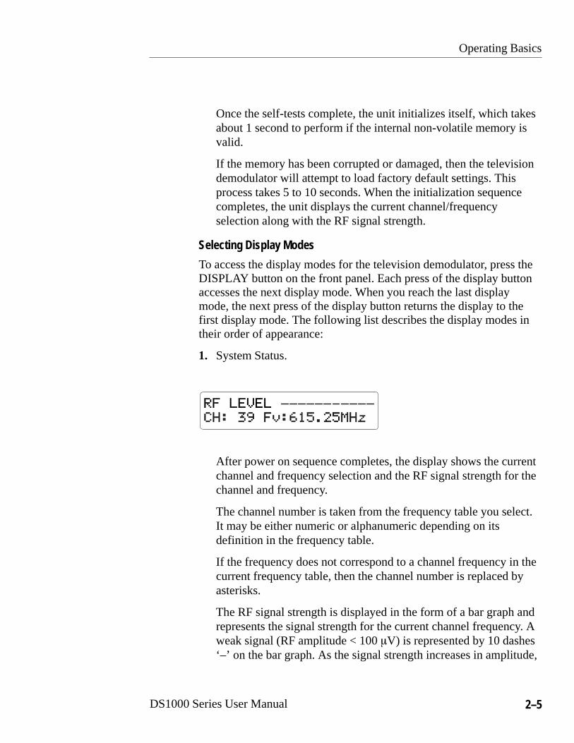
1. System Status.
After power on sequence completes, the display shows the currentchannel and frequency selection and the RF signal strength for thechannel and frequency.
The channel number is taken from the frequency table you select.It may be either numeric or alphanumeric depending on itsdefinition in the frequency table.
If the frequency does not correspond to a channel frequency in thecurrent frequency table, then the channel number is replaced byasterisks.
The RF signal strength is displayed in the form of a bar graph andrepresents the signal strength for the current channel frequency. Aweak signal (RF amplitude < 100 �V) is represented by 10 dashes‘–’ on the bar graph. As the signal strength increases in amplitude,

Operating Basics
2–6 DS1000 Series User Manual
the dashes are replaced by blocks ‘�’ from the left, until alldashes have been replaced (RF amplitude > 1 mV).
2. Audio Output Status.
The audio output display shows the current status of the audiosignals on the XLR connectors located on the rear panel.
3. Program Set-up.
The program set-up display allows you to view the configurationof the current program (preset). The top line shows the activeprogram number and the bottom lines shows the program items.Use the up and down buttons (↑ and ↓ ) to view the entireconfiguration by scrolling through the various program items.Refer to page 3–3 for a description of each item in the Program setup.
To change a Program, select the Program number here, then pressthe CONFIG button. Refer to Program Configuration on page 3–3for further instructions.
4. NICAM Error Count (PAL systems only).

Operating Basics
DS1000 Series User Manual 2–7
The error count gives the number of NICAM errors per 128 msperiod. Three versions of the error count are displayed:
Av – Average error count shows the average number of errorsover the last ten readings.
Pk – Peak error count shows peak errors and delays while theerror count is less than the displayed peak error count.
Ph – Peak hold error count shows the maximum error count. Itis updated if the latest error count exceeds the current peakhold error count.
All three error counts can be cleared by pressing the enter (↵ )button when in the Nicam error count display mode.
5. Product title.
The product title display shows the product number, transmissionstandard and unit serial number.
6. Firmware revision.
The firmware revision display shows the firmware number and therevision number of firmware in the television demodulator. Youwill need this revision number when reporting problems inoperation to Tektronix representatives.

Operating Basics
2–8 DS1000 Series User Manual
7. Temperature status.
The temperature status display shows when the internal SAW filterreaches its normal operating temperature. The status is one of thefollowing readouts:
� LOW. The television demodulator has not reached its normaloperating temperature.
� NORMAL. The television demodulator has reached its normaloperating temperature.
� HIGH. The television demodulator has exceeded its recom-mended operating temperature range.
Selecting a Program
The television demodulator can store and recall 20 different programs(presets) from non-volatile memory. Only one of the programs isactive at a time. Use the PROGRAM button to select a program.
Pressing the PROGRAM button brings up the program selectiondisplay. The the first line displays the current active program numberand the second line displays the program channel and frequency.
Use the up and down buttons (↑ and ↓ ) to select from the 20 storedprograms.
As each program number appears, its program configuration becomesactive. When you reach the required program number, pressing thedisplay button exits the program selection mode. The selected

Operating Basics
DS1000 Series User Manual 2–9
program becomes the active program and will be recalled the nexttime you power on the unit.
Adjusting the Current Program
You can temporarily adjust the channel number and frequency whilein the system status display. Use the up and down buttons (↑ and ↓ ) tochange the channel and the left and right buttons to change thefrequency. The changes you make are temporary and will be lost whenyou select another display mode or remove the AC power.

Operating Basics
2–10 DS1000 Series User Manual

Reference


DS1000 Series User Manual 3–1
Reference
This section describes how to configure the television demodulator tofit your application.
Configuring OperationThe television demodulator has many configurable parameters whichit stores in non-volatile memory. Use the Configuration menu to selectitems. Table 3–1 lists the configurable items in the sequence that theyappear.
Changes to program items immediately change the operation of thetelevision demodulator. This active control allows you to see theaffects of a change without exiting the program configuration mode. Ifselected changes do not give the desired result, you can discard thechanges by exiting the configuration mode using the ‘NO’ saveoption.
Refer to Appendix E for a list of factory default settings for allconfigurable items.
Table 3–1: Configure menu hierarchy
Configuremenu Selections Range
1 Program Frequency Table UHF, VHF, user defined
Channel Various
Frequency NTSC: 55.25 to 801.25 MHzPAL: 45.25 to 860.25 MHz
ZCP Status On, Off
ZCP Line Number NTSC: 10-20 (F1 & F2)PAL: 6-16, 319-329
ZCP Position 0 to 4

Reference
3–2 DS1000 Series User Manual
Table 3–1: Configure menu hierarchy (cont.)
RangeSelectionsConfiguremenu
Audio Preference NTSC: BTSCPAL: NICAM, FM
Audio Input Select NTSC: Mono, Mono-SAP, Stereo, SAPPAL: Mono1, Mono2, Mono1-Mono2, Stereo
AFC Status On, Off
Sound Trap On, Off
Stereo Noise NTSC: 1–16
SAP Noise NTSC: 1–16
2 FrequencyResponse
Manual FrequencyResponse Adjust
–10 to +10
3 ContrastAdjust
Display ContrastAdjust
Dark to Max brightness
4 User ChannelTable
Channel (1–50) NTSC: 55.25 to 801.25 MHzPAL: 45.25 to 860.25 MHz
5 Serial Set-up Serial Mode RS232, RS485
Unit Address 32 to 63
RTS/CTS Disabled, Enabled
RS485 Termination Unterminated, Terminated
Quick Guide
To configure the television demodulator, follow these procedures:
1. Press the front panel CONFIG button to access the Configurationmenu.
2. Use the up and down buttons (↑ and ↓ ) to select a configurationmode.
3. Press the enter button (↵ ) to enter the selected configuration mode.

Reference
DS1000 Series User Manual 3–3
4. Use the up and down buttons (↑ and ↓ ) to select a configurationitem. Use the left and right buttons (← and →) to change theselected configuration item.
5. Press the CONFIG button after making the desired changes. If youhave made no changes, then the Configuration menu returns. Ifyou have made changes, then you are asked if you want to save thechanges. Use the left and right buttons (← and →) to select eitheryes or no, then press the enter button (↵ ).
6. To exit the configuration mode, press the DISPLAY button.
Program ConfigurationThe Program selection in the Configure menu allows you to modify aProgram. Before entering the Configure menu, you must select theProgram number you wish to modify.
To modify a Program, press the Program button and use the up anddown buttons (↑ and ↓ ) to choose the program number you wish tomodify. Then press the CONFIG button to access the Configurationmenu. The top level selection is Program. Press the enter button (↵ ) toenter the Program Config menu. Use the up and down buttons (↑ and ↓ ) to choose and change any of the following selections:
1. Frequency tables.
Reference
3–4 DS1000 Series User Manual
The television demodulator contains a wide variety of frequencytables that list the channel assignments used in many countries.The channel assignments cover the standard television frequencyspectrum.
You can select a frequency table using the FT item. Only onefrequency table can be active for an individual program, butdifferent programs can use different frequency tables. Appendix Dincludes a complete list of the frequency tables.
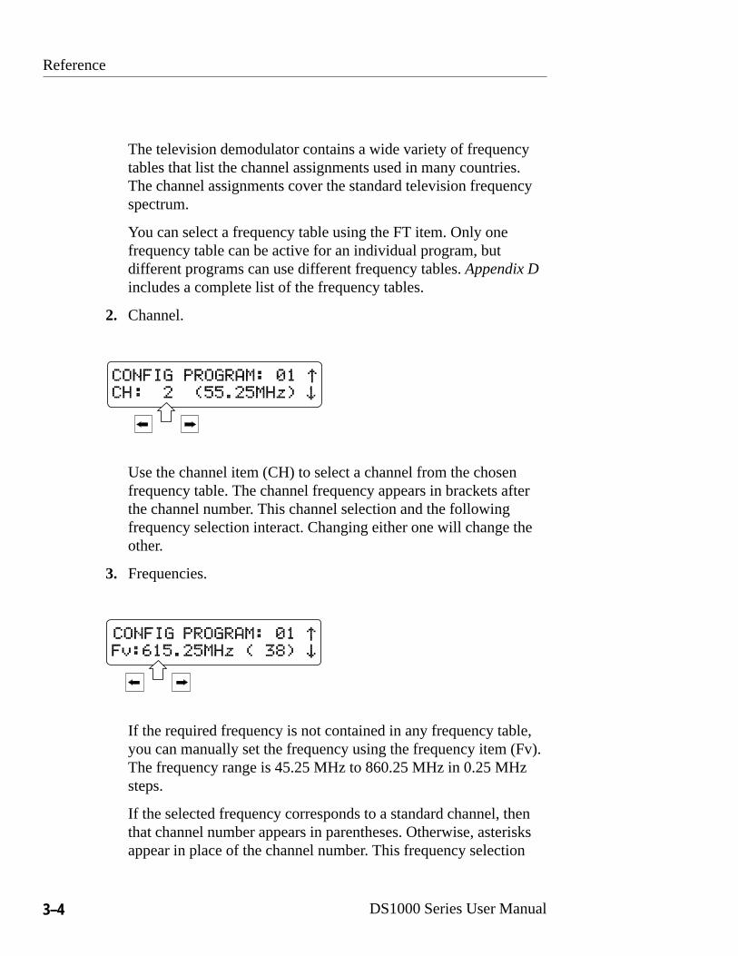
2. Channel.
Use the channel item (CH) to select a channel from the chosenfrequency table. The channel frequency appears in brackets afterthe channel number. This channel selection and the followingfrequency selection interact. Changing either one will change theother.
3. Frequencies.
If the required frequency is not contained in any frequency table,you can manually set the frequency using the frequency item (Fv).The frequency range is 45.25 MHz to 860.25 MHz in 0.25 MHzsteps.
If the selected frequency corresponds to a standard channel, thenthat channel number appears in parentheses. Otherwise, asterisksappear in place of the channel number. This frequency selection

Reference
DS1000 Series User Manual 3–5
and the previous channel selection interact. Changing either onewill change the other.
4. ZCP.
The zero carrier pulse (ZCP) is a special feature of the televisiondemodulator. You configure the ZCP feature using the ZCP status,ZCP line, and ZCP position items.
The ZCP status item determines whether the ZCP signal is on oroff.
ONOFF
The ZCP line setting determines on which video line the ZCP isactive. For PAL systems the line number range is 6 to 16 and 319 – 329. For NTSC systems the line number range is 10 to 20(F1) and 10 to 20 (F2).
The ZCP position item determines the start position of the ZCP onthe chosen video line. The five position choices are 0 to 4.

Reference
3–6 DS1000 Series User Manual
5. Audio Preference.
For NTSC systems, the audio preference is set to BTSC with noother options.
For PAL systems, the audio preference item determines whichaudio system has primary control. The choices are NICAM andFM. If the primary choice signal is not present, then the secondarychoice takes control.
6. Audio Input Selection.
The audio input selection item allows control of the audio outputson the rear panel. For PAL systems, the available choices areMONO1, MONO2, DUAL MONO and STEREO. For NTSCsystems, the available choices are MONO, MONO/SAP, STEREOand SAP.
7. AFC.
ONOFF
The AFC selection, when enabled, sets the tuning system of thetelevision demodulator to locate and lock to a frequency that drifts

Reference
DS1000 Series User Manual 3–7
or to a frequency that is between the standard 0.25MHz frequencysteps. The AFC function is not normally required for broadcastsignals and should be used with caution because of its limitedrange of �1 MHz about the video carrier frequency.
The options for the AFC item are either on or off.
8. Sound Trap.
ONOFF
The sound trap status item, when enabled, adds extra filtering toremove any sound element from the video signal. The options forthe sound trap item are either on or off.
9. BTSC Stereo/SAP Noise Thresholds.
The BTSC Stereo and SAP noise threshold items are only presenton NTSC systems and are used to switch stereo and SAP outputsoff when the thresholds are reached. The range for both items is 1 to 16.

Reference
3–8 DS1000 Series User Manual
Serial ConfigurationThe Serial Set–up selection in the Configure menu, allows you to setthe communications parameters of the serial port on the rear-panel.
To modify the serial port setup, press the CONFIG button to accessthe Configure menu. Use the up and down buttons (↑ and ↓ ) to selectSERIAL SET–UP. Press the enter button (↵ ) to enter the Config Serialmenu. Use the up and down buttons (↑ and ↓ ) to choose and changeany of the following selections:
1. Serial Mode.
Sets the mode of the serial port to either RS232 or RS485. Refer toSerial Port Connection on page B–1 for connection information.
2. Unit Address.
Sets the RS485 serial mode address. A controlling terminal or PCuses this address to identify and control a particular instrument.

Reference
DS1000 Series User Manual 3–9
The RS485 communications protocol allows connection ofmultiple units to one host. Each device connected to the host musthave a unique address. The range for the unit address is 32 to 63.
3. RS232 RTS/CTS status.
DISABLED ENABLED
Enables or disables hardware handshaking on the serial port whenin the RS232 serial mode.
4. RS485 termination.
TERMINATEDUNTERMINATED
Enables or disables termination at the television demodulator inthe RS485 serial mode. Enable termination when the televisiondemodulator is the last device in a multi-drop system. Selectunterminated when it is not the last device.

Reference
3–10 DS1000 Series User Manual
Frequency Response ConfigurationIn the television demodulator system there are two levels of frequencyresponse adjustment. The first is factory set and cannot be adjustedfrom the front panel. The second is the manual frequency responseitem which allows minor adjustments to the frequency response.
Use caution when changing the manual frequency response and do soonly when connected to equipment that can measure the changes tofrequency response.
The changes to frequency response affect only the current activefrequency, which is shown on the top line of the frequency responseconfiguration display. You can adjust several frequencies which arestored in the television demodulator non-volatile memory.
Due to memory limitations within the television demodulator, it isimpractical to store frequency response adjustments for every possiblefrequency, so the adjustments are possible only for the range offrequencies listed in Table 3–2.

Reference
DS1000 Series User Manual 3–11
Table 3–2: Frequency response adjustment bands
Low band Mid band High band
ÁÁÁÁÁÁÁÁÁÁÁÁÁÁ
40.00 – 47.75 MHz ÁÁÁÁÁÁÁÁÁÁÁÁÁÁ
170.00 – 179.75 MHzÁÁÁÁÁÁÁÁÁÁÁÁÁÁÁÁ
454.25 – 469.75 MHz
ÁÁÁÁÁÁÁÁÁÁÁÁÁÁ
48.00 – 55.75 MHz ÁÁÁÁÁÁÁÁÁÁÁÁÁÁ
180.00 – 189.75 MHzÁÁÁÁÁÁÁÁÁÁÁÁÁÁÁÁ
470.00 – 489.75 MHzÁÁÁÁÁÁÁÁÁÁÁÁÁÁ
56.00 – 63.75 MHz ÁÁÁÁÁÁÁÁÁÁÁÁÁÁ
190.00 – 199.75 MHzÁÁÁÁÁÁÁÁÁÁÁÁÁÁÁÁ
490.00 – 509.75 MHzÁÁÁÁÁÁÁÁÁÁÁÁÁÁ
64.00 – 71.75 MHzÁÁÁÁÁÁÁÁÁÁÁÁÁÁ
200.00 – 209.75 MHzÁÁÁÁÁÁÁÁÁÁÁÁÁÁÁÁ
510.00 – 529.75 MHzÁÁÁÁÁÁÁÁÁÁÁÁÁÁ
72.00 – 79.75 MHzÁÁÁÁÁÁÁÁÁÁÁÁÁÁ
210.00 – 219.75 MHzÁÁÁÁÁÁÁÁÁÁÁÁÁÁÁÁ
530.00 – 549.75 MHzÁÁÁÁÁÁÁÁÁÁÁÁÁÁÁÁÁÁÁÁÁ
80.00 – 87.75 MHzÁÁÁÁÁÁÁÁÁÁÁÁÁÁÁÁÁÁÁÁÁ
220.00 – 229.75 MHzÁÁÁÁÁÁÁÁÁÁÁÁÁÁÁÁÁÁÁÁÁÁÁÁ
550.00 – 569.75 MHz
ÁÁÁÁÁÁÁÁÁÁÁÁÁÁ
88.00 – 95.75 MHz ÁÁÁÁÁÁÁÁÁÁÁÁÁÁ
230.00 – 239.75 MHzÁÁÁÁÁÁÁÁÁÁÁÁÁÁÁÁ
570.00 – 589.75 MHz
ÁÁÁÁÁÁÁÁÁÁÁÁÁÁ
96.00 – 103.75 MHz ÁÁÁÁÁÁÁÁÁÁÁÁÁÁ
240.00 – 249.75 MHzÁÁÁÁÁÁÁÁÁÁÁÁÁÁÁÁ
590.00 – 609.75 MHz
ÁÁÁÁÁÁÁÁÁÁÁÁÁÁ
104.00 – 111.75 MHz ÁÁÁÁÁÁÁÁÁÁÁÁÁÁ
250.00 – 259.75 MHzÁÁÁÁÁÁÁÁÁÁÁÁÁÁÁÁ
610.00 – 629.75 MHz
ÁÁÁÁÁÁÁÁÁÁÁÁÁÁ
112.00 – 119.75 MHz ÁÁÁÁÁÁÁÁÁÁÁÁÁÁ
260.00 – 269.75 MHzÁÁÁÁÁÁÁÁÁÁÁÁÁÁÁÁ
630.00 – 649.75 MHzÁÁÁÁÁÁÁÁÁÁÁÁÁÁ
120.00 – 127.75 MHz ÁÁÁÁÁÁÁÁÁÁÁÁÁÁ
270.00 – 279.75 MHzÁÁÁÁÁÁÁÁÁÁÁÁÁÁÁÁ
650.00 – 669.75 MHzÁÁÁÁÁÁÁÁÁÁÁÁÁÁ
128.00 – 135.75 MHzÁÁÁÁÁÁÁÁÁÁÁÁÁÁ
280.00 – 289.75 MHzÁÁÁÁÁÁÁÁÁÁÁÁÁÁÁÁ
670.00 – 689.75 MHzÁÁÁÁÁÁÁÁÁÁÁÁÁÁ136.00 – 143.75 MHz
ÁÁÁÁÁÁÁÁÁÁÁÁÁÁ290.00 – 299.75 MHz
ÁÁÁÁÁÁÁÁÁÁÁÁÁÁÁÁ690.00 – 709.75 MHzÁÁÁÁÁÁÁ
ÁÁÁÁÁÁÁÁÁÁÁÁÁÁ
144.00 – 151.75 MHzÁÁÁÁÁÁÁÁÁÁÁÁÁÁÁÁÁÁÁÁÁ
300.00 – 309.75 MHzÁÁÁÁÁÁÁÁÁÁÁÁÁÁÁÁÁÁÁÁÁÁÁÁ
710.00 – 729.75 MHz
ÁÁÁÁÁÁÁÁÁÁÁÁÁÁ
152.00 – 159.75 MHz ÁÁÁÁÁÁÁÁÁÁÁÁÁÁ
310.00 – 319.75 MHzÁÁÁÁÁÁÁÁÁÁÁÁÁÁÁÁ
730.00 – 749.75 MHz
ÁÁÁÁÁÁÁÁÁÁÁÁÁÁ
160.00 – 162.75 MHz ÁÁÁÁÁÁÁÁÁÁÁÁÁÁ
320.00 – 329.75 MHzÁÁÁÁÁÁÁÁÁÁÁÁÁÁÁÁ
750.00 – 769.75 MHz
ÁÁÁÁÁÁÁÁÁÁÁÁÁÁ
163.00 – 167.75 MHz ÁÁÁÁÁÁÁÁÁÁÁÁÁÁ
330.00 – 339.75 MHzÁÁÁÁÁÁÁÁÁÁÁÁÁÁÁÁ
770.00 – 789.75 MHz
ÁÁÁÁÁÁÁÁÁÁÁÁÁÁ
168.00 – 169.75 MHz ÁÁÁÁÁÁÁÁÁÁÁÁÁÁ
340.00 – 349.75 MHzÁÁÁÁÁÁÁÁÁÁÁÁÁÁÁÁ
790.00 – 809.75 MHzÁÁÁÁÁÁÁÁÁÁÁÁÁÁ
ÁÁÁÁÁÁÁÁÁÁÁÁÁÁ
350.00 – 359.75 MHzÁÁÁÁÁÁÁÁÁÁÁÁÁÁÁÁ
810.00 – 829.75 MHzÁÁÁÁÁÁÁÁÁÁÁÁÁÁ
ÁÁÁÁÁÁÁÁÁÁÁÁÁÁ
360.00 – 369.75 MHzÁÁÁÁÁÁÁÁÁÁÁÁÁÁÁÁ
830.00 – 849.75 MHzÁÁÁÁÁÁÁÁÁÁÁÁÁÁ
ÁÁÁÁÁÁÁÁÁÁÁÁÁÁ370.00 – 379.75 MHz
ÁÁÁÁÁÁÁÁÁÁÁÁÁÁÁÁ850.00 – 860.25 MHzÁÁÁÁÁÁÁ
ÁÁÁÁÁÁÁÁÁÁÁÁÁÁ
ÁÁÁÁÁÁÁÁÁÁÁÁÁÁÁÁÁÁÁÁÁ
380.00 – 389.75 MHzÁÁÁÁÁÁÁÁÁÁÁÁÁÁÁÁÁÁÁÁÁÁÁÁÁÁÁÁÁÁÁ
ÁÁÁÁÁÁÁÁÁÁÁÁÁÁÁÁÁÁÁÁÁ
390.00 – 399.75 MHzÁÁÁÁÁÁÁÁÁÁÁÁÁÁÁÁÁÁÁÁÁÁÁ
ÁÁÁÁÁÁÁÁÁÁÁÁÁÁÁÁÁÁÁÁÁ
400.00 – 409.75 MHzÁÁÁÁÁÁÁÁÁÁÁÁÁÁÁÁ

Reference
3–12 DS1000 Series User Manual
Table 3–2: Frequency response adjustment bands (cont.)
Low band High bandMid band
ÁÁÁÁÁÁÁÁÁÁÁÁÁÁ
ÁÁÁÁÁÁÁÁÁÁÁÁÁÁ
410.00 – 419.75 MHz ÁÁÁÁÁÁÁÁÁÁÁÁÁÁÁÁÁÁÁÁÁ
ÁÁÁÁÁÁÁÁÁÁÁÁÁÁÁÁÁÁÁÁÁ
420.00 – 429.75 MHz ÁÁÁÁÁÁÁÁÁÁÁÁÁÁÁÁÁÁÁÁÁ
ÁÁÁÁÁÁÁÁÁÁÁÁÁÁÁÁÁÁÁÁÁ
430.00 – 439.75 MHz ÁÁÁÁÁÁÁÁÁÁÁÁÁÁÁÁÁÁÁÁÁ
ÁÁÁÁÁÁÁÁÁÁÁÁÁÁÁÁÁÁÁÁÁ
440.00 – 454.00 MHzÁÁÁÁÁÁÁÁÁÁÁÁÁÁ
Contrast AdjustmentThe Contrast Adjust selection in the Configure menu, allows you toset the contrast of the front-panel LCD display.
To modify the contrast, press the CONFIG button to access theConfigure menu. Use the up and down buttons (↑ and ↓ ) to selectContrast Adjust. Press the enter button (↵ ) to enter the ContrastAdjustment menu.
Use the left and right buttons (← and →) to set the contrast lower orhigher as appropriate for the ambient light level. Press the enter button(↵ ) when you have finished.

Reference
DS1000 Series User Manual 3–13
User Defined Channel TableThe User Channel Table selection in the Configure menu, allows youto store several custom channel and frequency combinations in theUser Channel Table.
To create or modify the User Channel Table, press the CONFIGbutton to access the Configure menu. Use the up and down buttons (↑ and ↓ ) to select the User Channel Table. Press the enter button (↵ )to enter the User Channel Table menu.
The television demodulator can store several custom channels andfrequencies. You can select from channels 1 to 50 using the up anddown arrow keys. Use the left and right arrow keys to set the newfrequency for the channel. The channel frequency is saved when youeither press the Config button or select another channel.
You select the User Defined channel table as you do other frequencyand channel tables. Refer to Program Configuration on page 3–3 forinstructions on selecting a frequency table.

Reference
3–14 DS1000 Series User Manual

Appendices

DS1000 Series User Manual A–1
Appendix A: Performance Specifications
The instrument specifications listed in this section are eitherperformance requirements or reference information.
Performance requirements are valid over an ambient temperaturerange of 5°C to 35°C, unless otherwise noted. Ensure that testequipment used to verify performance requirements is calibrated andworking within its specified limits.
Reference information, marked RI, amplifies a performancerequirement or provides useful information on other operatingparameters.
This section contains the following specifications:
� Table A–1 Video specifications
� Table A–2 Audio specifications
� Table A–3 Electrical specifications – power requirements
� Table A–4 Environmental characteristics
� Table A–5 Physical characteristics
� Table A–6 Certifications and compliances
� Table A–7 Safety certification compliance
� Table A–8 Safety standards
Appendix A: Performance Specifications
A–2 DS1000 Series User Manual
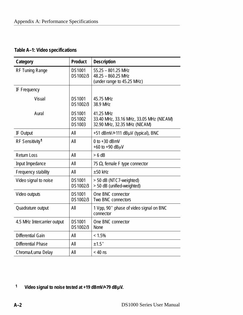
Table A–1: Video specifications
Category Product Description
RF Tuning Range DS1001DS1002/3
55.25 – 801.25 MHz48.25 – 860.25 MHz (under range to 45.25 MHz)
IF Frequency
Visual
Aural
DS1001DS1002/3
DS1001DS1002DS1003
45.75 MHz38.9 MHz
41.25 MHz33.40 MHz, 33.16 MHz, 33.05 MHz (NICAM)32.90 MHz, 32.35 MHz (NICAM)
IF Output All +51 dBmV/+111 dB�V (typical), BNC
RF Sensitivity1 All 0 to +30 dBmV+60 to +90 dB�V
Return Loss All > 6 dB
Input Impedance All 75 �, female F type connector
Frequency stability All ±50 kHz
Video signal to noise DS1001DS1002/3
> 50 dB (NTC7-weighted)> 50 dB (unified-weighted)
Video outputs DS1001DS1002/3
One BNC connectorTwo BNC connectors
Quadrature output All 1 Vpp, 90� phase of video signal on BNCconnector
4.5 MHz Intercarrier output DS1001DS1002/3
One BNC connectorNone
Differential Gain All < 1.5%
Differential Phase All ±1.5�
Chroma/Luma Delay All < 40 ns
1 Video signal to noise tested at +19 dBmV/+79 dB�V.
Appendix A: Performance Specifications
DS1000 Series User Manual A–3
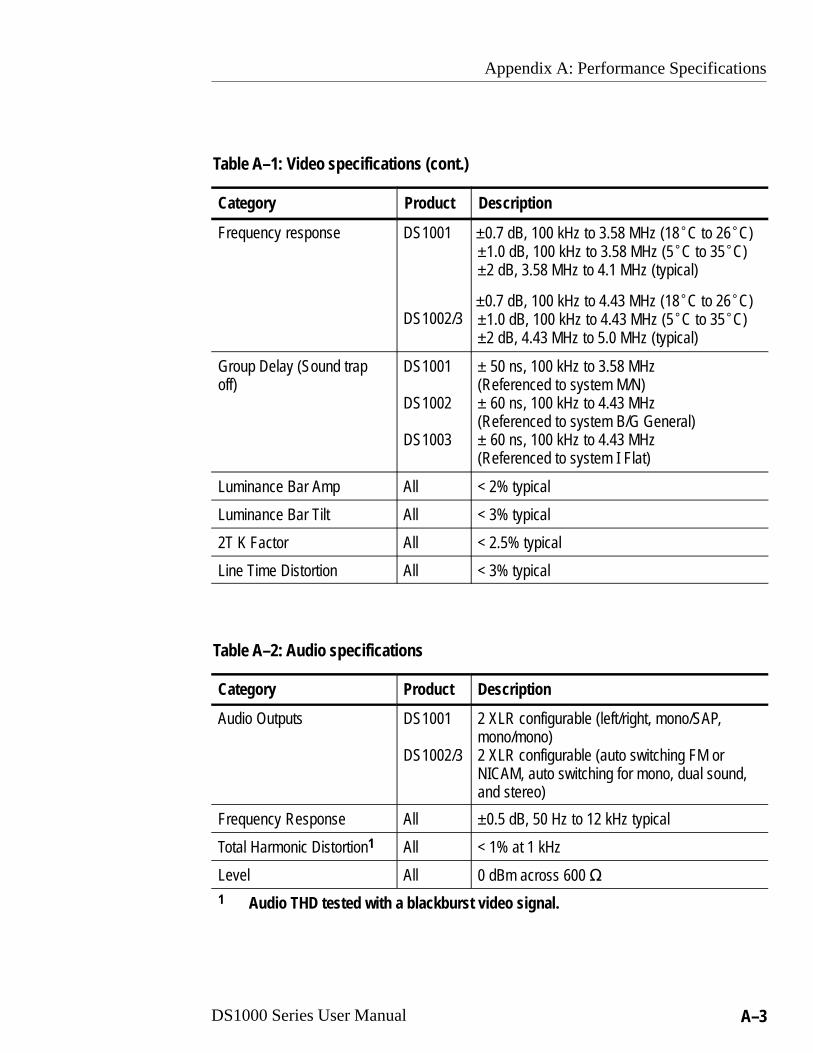
Table A–1: Video specifications (cont.)
Category DescriptionProduct
Frequency response DS1001
DS1002/3
±0.7 dB, 100 kHz to 3.58 MHz (18�C to 26�C)±1.0 dB, 100 kHz to 3.58 MHz (5�C to 35�C)±2 dB, 3.58 MHz to 4.1 MHz (typical)
±0.7 dB, 100 kHz to 4.43 MHz (18�C to 26�C)±1.0 dB, 100 kHz to 4.43 MHz (5�C to 35�C)±2 dB, 4.43 MHz to 5.0 MHz (typical)
Group Delay (Sound trapoff)
DS1001
DS1002
DS1003
± 50 ns, 100 kHz to 3.58 MHz(Referenced to system M/N)± 60 ns, 100 kHz to 4.43 MHz(Referenced to system B/G General)± 60 ns, 100 kHz to 4.43 MHz(Referenced to system I Flat)
Luminance Bar Amp All < 2% typical
Luminance Bar Tilt All < 3% typical
2T K Factor All < 2.5% typical
Line Time Distortion All < 3% typical
Table A–2: Audio specifications
Category Product Description
Audio Outputs DS1001
DS1002/3
2 XLR configurable (left/right, mono/SAP,mono/mono)2 XLR configurable (auto switching FM orNICAM, auto switching for mono, dual sound,and stereo)
Frequency Response All ±0.5 dB, 50 Hz to 12 kHz typical
Total Harmonic Distortion1 All < 1% at 1 kHz
Level All 0 dBm across 600 �1 Audio THD tested with a blackburst video signal.

Appendix A: Performance Specifications
A–4 DS1000 Series User Manual
Table A–3: Electrical specifications – power requirements
Category Description
Line Voltage Ranges 95 to 240 VAC ±10%
Power Consumption 30 VA Maximum
Line Frequency 50/60 Hz
Fuse 1.6AT, 250 V (20 mm ceramic)
Table A–4: Environmental characteristics
Category Description
Operating Temperature 5� C to 35� C
Storing Temperature –20� C to 75� C
Operating Altitude 6500 ft maximum (2,000 m)
Non-operating Altitude 50,000 ft maximum (15,000 m)
Relative Humidity (maximumoperating)
80% for temperatures up to 31� C, decreasing linearly to50% at 40� C
Table A–5: Physical characteristics
Category Description
Dimensions Height: 1.8 in (46 mm)Width: 8.1 in (206 mm)Depth: 17.3 in (440 mm)
Weight Net Weight: 4.8 lbs (2.2 kg)

Appendix A: Performance Specifications
DS1000 Series User Manual A–5
Table A–6: Certifications and compliances
Category Description
EC Declaration ofConformity – EMC
Meets intent of Directive 89/336/EEC for ElectromagneticCompatibility. Compliance was demonstrated to thefollowing specifications as listed in the Official Journal of theEuropean Communities:
EN 50081-1 Emissions:2EN 55022 Class B Radiated and Conducted
EmissionsEN 60555-2 AC Power Line Harmonic Emissions
EN 50082-1 Immunity:2IEC 801-2 Electrostatic Discharge ImmunityIEC 801-3 RF Electromagnetic Field ImmunityIEC 801-4 Electrical Fast Transient/Burst
ImmunityIEC 801-5 Power Line Surge Immunity
2 High-quality shielded cables must be used to ensurecompliance.
Austrailia/New ZealandDeclaration of Conformity –EMC
Complies with EMC provision of Radiocommunications Actper the following standard(s):
AN/NZS 2064.1/2 Industrial, Scientific, and Medical Equipment: 1992
FCC Compliance Emissions comply with FCC Code of Federal Regulations47, Part 15, Subpart B, Class A Limits3
3 High-quality shielded cables must be used to ensurecompliance.
EC Declaration ofConformity – Low Voltage
Compliance was demonstrated to the following specificationas listed in the Official Journal of the EuropeanCommunities:
Low Voltage Directive 73/23/EEC, Amended by 93/68/EEC
EN 61010-1:1993 Safety requirements for electrical equipment formeasurement, control, and laboratory use
Approvals ANSI/ISA S82.01 – Safety standard for electrical andelectronic test, measuring, controlling, and relatedequipment, 1994

Appendix A: Performance Specifications
A–6 DS1000 Series User Manual
Table A–6: Certifications and compliances (cont.)
Category Description
UL3111-1 – Standard for electrical measuring and testequipment
CAN/CSA C22.2 No. 1010.1 – Safety requirements forelectrical equipment for measurement, control andlaboratory use
Installation CategoryDescriptions
Terminals on this product may have different installationcategory designations. The installation categories are:
CAT III Distribution-level mains (usually permanently connected). Equipment at this level is typically in a fixed industrial location
CAT II Local-level mains (wall sockets). Equipment at this level includes appliances, portable tools, and similar products. Equipment is usually cord-connected
CAT I Secondary (signal level) or battery operated circuits of electronic equipment
Table A–7: Safety certification and compliance
Category Description
Temperature (operating) +5� C to +40� C
Altitude (maximum operat-ing)
6500 feet (2000 meters)
Relative Humidity (maximumoperating)
80% for temperatures up to 31� C, decreasing linearly to50% at 40� C
Equipment Type Test and Measuring
Safety Class Class I (as defined in IEC 1010-1, Annex H) – groundedproduct
Installation Category Installation category II (as defined in IEC 1010-1, Annex J)
Pollution Degree Pollution Degree 2 (as defined in IEC 1010-1)Note: Rated for indoor use only.

Appendix A: Performance Specifications
DS1000 Series User Manual A–7
Table A–8: Safety standards
Category Description
U.S. Nationally RecognizedTesting Laboratory Listing
ANSI/ISA S82.01 – Safety Standard for Electrical andElectronic Test, Measuring, Controlling, and RelatedEquipment, 1994
UL3111-1 - Standard for Electrical Measuring and TestEquipment
Canadian Certification CAN/CSA C22.2 No. 1010.1 - Safety Requirements forElectrical Equipment for Measurement, Control, andLaboratory Use.
European Union Com-pliance
Low Voltage Directive 73/23/EEC, Amended by 93/68/EEC
EN61010-1 - Safety Requirements for Electrical Equipmentfor Measurement, Control, and Laboratory Use.
Additional Compliance IEC1010-1 - Safety Requirements for Electrical Equipmentfor Measurement, Control, and Laboratory Use.

Appendix A: Performance Specifications
A–8 DS1000 Series User Manual

DS1000 Series User Manual B–1
Appendix B: Remote Control
This appendix describes how to remotely control the televisiondemodulator. This appendix provides the following information:
� Serial port connection
� Programming model
� Command syntax descriptions
� Alphabetical list of commands
Serial Port Connection
CAUTION. Connecting or disconnecting cables while the televisiondemodulator is powered on can result in damage to its input circuits.
The rear panel SERIAL connector allows remote control of thetelevision demodulator using a PC controller. The connector is a 9-pin,subminiature D-type with female contacts. Table B–1 and Figure B–1give the pin configuration for the SERIAL connector.
The SERIAL connector provides a configurable serial communica-tions port. You can configure the serial port as either RS232 or RS485using the Serial Configuration menu. Refer to page 3–8.

Appendix B: Remote Control
B–2 DS1000 Series User Manual
5 4 3 2 1
9 8 7 6
Figure B–1: Pin assignments for the SERIAL connector
Table B–1: Rear-panel SERIAL port connections
Pin Function Pin Function
1 RS485 B 6 Not Used
2 RS232 TxD 7 RS232 CTS
3 RS232 RxD 8 RS232 RTS
4 Not Used 9 RS485 A
5 Signal Ground
Before initiating remote control of the television demodulator, set thePC serial port as follows:
PC Serial Port SettingsÁÁÁÁÁÁÁÁÁÁÁÁ
Speed ÁÁÁÁÁÁÁÁÁÁÁÁÁÁÁÁÁÁÁÁÁÁÁÁÁÁÁÁ9600 bps
ÁÁÁÁÁÁÁÁÁÁÁÁProtocol
ÁÁÁÁÁÁÁÁÁÁÁÁÁÁÁÁÁÁÁÁÁÁÁÁÁÁÁÁ1 start bit, 8 data bits, no parity, 1 stop bitÁÁÁÁÁÁ
ÁÁÁÁÁÁÁÁÁÁÁÁ
InterfaceÁÁÁÁÁÁÁÁÁÁÁÁÁÁÁÁÁÁÁÁÁÁÁÁÁÁÁÁÁÁÁÁÁÁÁÁÁÁÁÁÁÁ
RS485 or RS232 (match the television demodulatorsetting)
Handshaking RS232 only, use RTS/CTS hardware handshaking (matchthe television demodulator setting)

Appendix B: Remote Control
DS1000 Series User Manual B–3
Programming ModelThe television demodulator uses the BCP Simplified CommunicationLink protocol (SCL). With the SCL Protocol, you program a PC tosend and receive data using standard I/O functions found in mostprogramming languages, such as C, PASCAL, and BASIC.
The SCL protocol supports asynchronous binary communication, nottext or ASCII based. Communication is based on 8-bit bytes rangingfrom 0 to 255. Table B–2 lists special byte codes used to coordinatedata transfers between the PC and the television demodulator. Forinformation on how to use these special byte codes, refer to Sendingand Receiving Data on page B–5.
Table B–2: Special byte codes
Code mne-monic ASCII Description
Controlcharacters
ÁÁÁÁÁÁÁÁÁÁ
STX ÁÁÁÁÁÁÁÁ
02 hex ÁÁÁÁÁÁÁÁÁÁÁÁÁÁÁÁÁÁ
Start of data ÁÁÁÁÁÁÁÁÁÁ
^B
ÁÁÁÁÁÁÁÁÁÁ
ETX ÁÁÁÁÁÁÁÁ
03 hex ÁÁÁÁÁÁÁÁÁÁÁÁÁÁÁÁÁÁ
End of data ÁÁÁÁÁÁÁÁÁÁ
^C
ÁÁÁÁÁÁÁÁÁÁ
ENQ ÁÁÁÁÁÁÁÁ
05 hex ÁÁÁÁÁÁÁÁÁÁÁÁÁÁÁÁÁÁ
Enquiry ÁÁÁÁÁÁÁÁÁÁ
^E
ÁÁÁÁÁÁÁÁÁÁ
DLE ÁÁÁÁÁÁÁÁ
10 hex ÁÁÁÁÁÁÁÁÁÁÁÁÁÁÁÁÁÁ
Data link escape ÁÁÁÁÁÁÁÁÁÁ
^PÁÁÁÁÁÁÁÁÁÁ
ACKO ÁÁÁÁÁÁÁÁ
11 hex ÁÁÁÁÁÁÁÁÁÁÁÁÁÁÁÁÁÁ
Device is ready ÁÁÁÁÁÁÁÁÁÁ
^QÁÁÁÁÁÁÁÁÁÁ
WACKÁÁÁÁÁÁÁÁ
3B hexÁÁÁÁÁÁÁÁÁÁÁÁÁÁÁÁÁÁ
Device is not readyÁÁÁÁÁÁÁÁÁÁ
;ÁÁÁÁÁÁÁÁÁÁÁÁÁÁÁ
AdÁÁÁÁÁÁÁÁÁÁÁÁ
0F hexÁÁÁÁÁÁÁÁÁÁÁÁÁÁÁÁÁÁÁÁÁÁÁÁÁÁÁ
Device addressÁÁÁÁÁÁÁÁÁÁÁÁÁÁÁ
^O
ÁÁÁÁÁÁÁÁÁÁ
Ar ÁÁÁÁÁÁÁÁ
* ÁÁÁÁÁÁÁÁÁÁÁÁÁÁÁÁÁÁ
User-defined remote addressÁÁÁÁÁÁÁÁÁÁÁÁÁÁÁ
ÁÁÁÁÁArs ÁÁÁÁ
ÁÁÁÁAr x 2 ÁÁÁÁÁÁÁÁÁ
ÁÁÁÁÁÁÁÁÁSend remote address ÁÁÁÁÁ
ÁÁÁÁÁÁÁÁÁÁÁÁÁÁÁ
Arr ÁÁÁÁÁÁÁÁ
Ar x 2 + 1 ÁÁÁÁÁÁÁÁÁÁÁÁÁÁÁÁÁÁ
Receive remote address ÁÁÁÁÁÁÁÁÁÁ* You assign the remote address. For more information, refer to
Addresses on page B–3.
Addresses
The television demodulator has four addresses that are necessary forcommunication using the SCL protocol. Table B–2 lists the fouraddresses: Ad, Ar, Ars, and Arr. For information on using these

Appendix B: Remote Control
B–4 DS1000 Series User Manual
addresses, refer to page B–5. The addresses perform the followingfunctions:
� Device address (Ad) is set to 0F hex in all television demodulators.The PC uses the device address to initiate communication with atelevision demodulator.
� Remote address (Ar) is unique for each television demodulator.You set this unique address as a decimal number. To set theaddress, use the SERIAL SET–UP item in the configuration menu.The remote address is the base address used to determine the Arsand Arr addresses.
� Send remote address (Ars) is used to send data to the televisiondemodulator. Calculate Ars using the following equation:
Ars = Ar x 2
� Receive remote address (Arr) is used to receive data from thetelevision demodulator. Calculate Arr using the followingequation:
Arr = Ar x 2 + 1
For example, if you set the remote address (Ar) to 50 decimal(32 hex), its SCL protocol addresses are as follows:
Ad (from Table B–2) = 0F hex
Ars = (32 hex) x 2 = 64 hex
Arr = (32 hex) x 2 + 1 = 65 hex
Remote Operation Flag
Some commands can be used only when the television demodulator isin the remote controlled state. When in remote control state, youcannot control the television demodulator from the front panel. Thefront panel display indicates the remote control state with the message“REMOTE CONTROLLED”
Two commands control the state of the remote flag. Use the commandPWD= to enter the remote control state and set the remote flag totrue (1). Use the DISC= command to resume front panel control andset the remote flag to false (0). Use the LOG? query to get the currentstate of the remote flag.

Appendix B: Remote Control
DS1000 Series User Manual B–5
Command Types
There are two types of commands.
� Select commands end with an equal sign (=), such as “PRESET=”.Select commands set the television demodulator to operate in anymode allowed from the front panel.
� Query commands end with a question mark (?), such as “PRE-SET?”. Query commands tell the television demodulator toprepare to send a particular type of data to the PC.
Commands may be followed by one or more parameters specific to thecommand. Parameters are in binary format. Query commands often donot require parameters. The response data from a query command maycontain several parameters.
For information on the syntax used for command definitions, refer topage B–11. The alphabetical list of commands and their parametersbegins on page B–13.
Sending and Receiving DataThe PC must send commands and addresses in a certain order whenwriting data to and reading data from the television demodulator. Themain steps in the communications process are as follows:
1. Send the identifying addresses.
2. Detect readiness of the television demodulator.
3. Send command and parameters.
4. Receive response/data.
Several types of communications are possible. Each type has a patternof commands or phases that must be used. The following discussionsintroduce these communication phases: send address, send data,receive address, poll for messages, and get messages.
Send Address Phase
The PC uses Ad and Ars to address a particular television demodula-tor. The television demodulator configured with a matching addressanswers with either a ready response or a not ready response. Sending

Appendix B: Remote Control
B–6 DS1000 Series User Manual
this address data aborts all other communication on the bus. Thefollowing three cases show variations of the send address phase.
The PC addresses a television demodulator that is not ready to receivedata:
� � ���� ����� ���� ����� Addressing phase
������ � ���� ����� Not ready response
The PC addresses a television demodulator that is ready, and the PCsends data:
� � ���� ����� ���� ����� Addressing phase
������ � ���� ����� ���� ����� Ready response
� � ���� ����� ������ ���� ����� Data phase
The PC addresses a television demodulator that is not ready, ignoresthe not ready response, and sends data:
� � ���� ����� ���� ����� Addressing phase
������ � ���� Aborted ready response
� � ���� ����� ������ ���� ����� Data phase
The PC can ignore the not-ready response and transmit the addressingphase and data phase sequentially. In this case, the televisiondemodulator aborts the not ready response after receiving the first byteof the data phase. The PC receives only a DLE character.
When sending data, Ad and Ars can be replaced by FF hex, abroadcast address. When the television demodulator sends a readyresponse, it will send its real address. You can use this broadcastaddress to determine the address of a television demodulator. The wildcard remote address is always a send address phase.
Send Data Phase
The send data phase begins with a command and may be followed byone or more parameters specific to the command. Two techniques forsending data are possible.
The PC addresses a television demodulator that is ready and sendsdata:
� � ���� ����� ���� ����� Addressing phase

Appendix B: Remote Control
DS1000 Series User Manual B–7
������ � ���� ����� ���� ����� Ready response
� � ���� ����� ������ ���� ����� Data phase
The PC addresses a television demodulator that is not ready, ignoresthe not ready response, and sends data:
� � ���� ����� ���� ����� Addressing phase
������ � ���� Aborted ready response
� � ���� ����� ������ ���� ����� Data phase
The PC can ignore the not-ready response and transmit the addressingphase and data phase sequentially. In this case, the televisiondemodulator aborts the not ready response after receiving the first byteof the data phase. The PC receives only a DLE character.
If the byte 10 hex is part of the data, this byte is sent twice so that it isnot confused with DLE ETX (10 hex), which ends the data phase.
Receive Address Phase
To acquire data from the television demodulator, the PC first sends theAd and Arr addresses to identify the television demodulator. Thisaddress phase aborts other communication on the same bus. Thetelevision demodulator responds with a not ready phase if it does nothave the requested data. It responds with a ready phase followed by adata phase when it has data. The receive data phase contains the Adand Arr addresses to identify the responding television demodulator.
Examples of receive communication between the PC and thetelevision demodulator follows with descriptions in italics.
The PC addresses a television demodulator that has no data available:
� � ���� ����� ���� ����� Addressing phase
������ � ���� ����� Not Ready response
The PC addresses a television demodulator that has data available, andthe television demodulator returns the data:
� � ���� ����� ���� ����� Addressing phase
������ � ���������������������������������
Ready response and data phase

Appendix B: Remote Control
B–8 DS1000 Series User Manual
If the byte 10 hex is part of the data, this byte is sent twice so that it isnot confused with DLE ETX (10 hex), which ends the data phase.
Polling for Status Messages
If a television demodulator has a message, it does not send it to thePC, because more than one television demodulator can be connectedto the same remote interface bus. To avoid data contention, the PCuses polling to check for messages.
Polling is done with the PATH? command. PATH? returns an emptystring if the television demodulator has no message, and returns thepath if a message is available. The path contains the addresses Ad andArs (see Addresses on page B–3).
The following example is one continuous polling communicationbetween the PC and the television demodulator. The values for Ad,Ars, and Arr can be calculated according to instructions on page B–3.
The PC addresses a television demodulator that is busy, repeats theaddressing phase until the television demodulator returns a readyphase, then the PC sends the “PATH?” command.
�� � � � ���� ���� ����� Send Addressing phase
����� �� � ������ Not Ready response
�� � � � ���� ���� ����� Send Addressing phase
����� � � � ������ ���� ����� Ready response
�� � � � ����� ��������� � � ���� Data phase
After receiving the PATH? command, the television demodulatorplaces its answer in its transmit buffer. The PC tries to retrieve themessage with a receive cycle, but the television demodulator has notprocessed the answer yet.
�� � � � ���� ���� ����� Receive Addressing phase
����� � � � ������ Not Ready phase
The PC repeats the addressing phase until the television demodulatoris ready and transmits its data phase. There is no data included,because the television demodulator has no message.
�� � � � ���� ���� ����� Receive Addressing phase

Appendix B: Remote Control
DS1000 Series User Manual B–9
����� � ���� ����� ���� ����� ���� �����
Data phase
The PC continuously polls the television demodulator.
� � ���� ����� ���� ����� Send Addressing phase
����� � ���� ����� ���� ����� Ready phase
� � ���� ����� ����� ��� ���� ����� Data phase
� � ���� ����� ���� ����� Receive Addressing phase
The television demodulator responds with data when it has a message.The [data] is the path, Ad Ars, which indicates that a message isavailable from the responding television demodulator.
����� ����� ����� ���� ����� ������ ���� �����
Data phase
Getting a Message
Polling a television demodulator only tells the PC if a message isavailable. To receive the message, you must use the MSG? command.
The following example shows how to use the MSG? command toretrieve a status message from a television demodulator.
The PC addresses a television demodulator that is busy and repeats theaddressing phase until the television demodulator returns a readyphase. The PC then sends the “MSG?” command.
� ����� ����� ���� ����� Send Addressing phase
����� � ���� ����� ���� ����� Ready phase
� � ���� ����� �������� ���� ����� Data phase
After receiving the MSG? command, the television demodulatorplaces its answer in its transmit buffer, and the PC retrieves themessage with a receive phase. The data in this example (20h) is thetest message. Other bit patterns are listed with the MSG? command.
� � ���� ����� ���� ����� Receiving addressing phase
����� � ���� ����� ���� ����� ����� ���� �����
Data phase

Appendix B: Remote Control
B–10 DS1000 Series User Manual
The PC acknowledges the data by sending the MSG= commandfollowed by the data bit pattern. The PC resumes polling, but clearsthe message data as it reads the message.
� � ���� ����� ���� ����� Send addressing phase
����� � ���� �� �� ���� ����� Ready phase
� � ���� ����� �������� ����� ���� ����� Data phase

Appendix B: Remote Control
DS1000 Series User Manual B–11
Command SyntaxThe command descriptions follow a consistent format. The elementsof that format are discussed here.
Description. Gives the function of the command, conditions of its use,and its interactions with other commands.
Syntax. Gives the valid select and query command forms. The requiredarguments are listed in their proper order.
For example, in the syntax definition
����� �������
the arguments <Ad> and <Ars> are required in the order indicated.
Arguments. The arguments to a command are defined along with theirrange of values.
Returns. Defines the data returned in response to a command query.
Data Types
Data sent with a command or received from a query may be of thetypes listed in Table B–3.
Table B–3: Data types used in remote communication
Data type Description
byte 8 bits, ordered highest to lowest (b7, b6, b5, b4, b3, b2,b1, b0).
word 16 bits, sent as 2 bytes, with the MSB first.
character (char) Transferred as a single byte, representing an ASCIIcharacter. Char(10) would indicate a string containing10 characters, such as ‘ABCDEFGHIJ’.
Boolean 0 or 1, representing an off or on state.
bitmap A string of bits with a definite length, where each bitrepresents the state of a parameter.

Appendix B: Remote Control
B–12 DS1000 Series User Manual
Data Offset
The offset is the relative position of a data item in the transmitted orreceived data. The first bit in a data transfer is number 1, so the firstbyte has an offset of 1.

Appendix B: Remote Control
DS1000 Series User Manual B–13
Remote Command Descriptions
The following remote commands appear in alphabetical order.
AFCSets or requests the current AFC status. The television demodulatormust be in the remote state to use this command.
AFC=AFC?
<afc_state> Either 0 for off or 1 for on.
Command Result
������ � AFC control is set to on.
Syntax
Arguments
Examples

Appendix B: Remote Control
B–14 DS1000 Series User Manual
AUD_OUTSelects or requests the audio output mode. The television demodulatormust be in the remote state to use this command.
AUD_OUT= <aud_val>AUD_OUT? <aud_status>
Argument Format Description
<aud_val> byte Left/Right (PAL) Left/Right (NTSC)0: Mono1/Mono1 Mono/Mono1: Mono2/Mono2 Mono/SAP2: Mono1/Mono2 Stereo/Stereo3: Stereo/Stereo SAP/SAP
<aud_status> byte 0: Mute1: FM/Nicam Mono12: FM/Nicam Mono23: FM/Nicam Mono1/Mono24: Stereo5: BTSC SAP6: BTSC Mono7: BTSC Mono/SAP8: BTSC Mono/Mute
Command Result
������� � Audio output mode set to dual mono for PAL systems, orstereo for NTSC systems.
Syntax
Arguments
Examples
Appendix B: Remote Control
DS1000 Series User Manual B–15
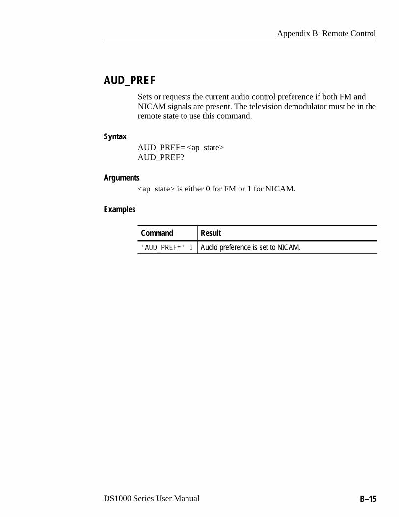
AUD_PREFSets or requests the current audio control preference if both FM andNICAM signals are present. The television demodulator must be in theremote state to use this command.
AUD_PREF= <ap_state>AUD_PREF?
<ap_state> is either 0 for FM or 1 for NICAM.
Command Result
��������� � Audio preference is set to NICAM.
Syntax
Arguments
Examples

Appendix B: Remote Control
B–16 DS1000 Series User Manual
BTSCSets or requests the stereo and SAP noise threshold for the BTSCcontroller. The television demodulator must be in the remote state touse this command.
BTSC= <stnt_val><sapnt_val>BTSC?
Byteoffset Argument Format Description
1 <stnt_val> byte Sets the stereo noise threshold in theBTSC controller. Range is 0 to 15.
2 <sapnt_val> byte Sets the SAP noise threshold in theBTSC controller. Range is 0 to 15
Command Result
���� �� � BTSC stereo noise threshold set to level 10.BTSC SAP noise threshold set to level 7.
Syntax
Arguments
Examples

Appendix B: Remote Control
DS1000 Series User Manual B–17
CHANNELSets or requests the selected channel record number and frequencytable of the television demodulator. Sending the CHANNEL=command automatically sets the tuning mode to CHANNEL. Thetelevision demodulator must be in the remote state to use thiscommand. For the query command, set TUNING to mode 0.
CHANNEL=<table><channel_rec>CHANNEL?
Byteoffset
Argu-ment Description
1 <table> Selects the table of channels from one of the following:
NTSC:0: User defined table1: CATV HRC2: CATV IRC3: CATV STD4: STDOFST5: IRC6: HRC7: B’CAST
PAL:0: User defined table1: UHF EUROPA2: UHF CHINA3: VHF EUROPA4: VHF FRANCE5: VHF ITALY6: VHF AUSTRALIA7: VHF CHINA8: VHF IRELAND9: VHF N. ZEALAND10: VHF S. AFRICA11: VHF OIRT12: VHF CCIR
2 <chan-nel_rec>
Selects the record number in the selected table. Thetable record number corresponds to a particular channelnumber. Refer to Appendix D for the record numberassociated with each channel number in the selectedtable.
Syntax
Arguments

Appendix B: Remote Control
B–18 DS1000 Series User Manual
Command Result
�������� �� NTSC:Table 1, CATV HRC frequency table is selected.Channel record 18 selected = channel number 19
PAL:UHF EUROPA frequency table selected.Channel record 18 selected = channel number 39
DISCPuts the television demodulator in the local state, which enables thefront panel controls and clears the remote flag. Use the commandPWD to enter the remote state and set the remote flag.
DISC=
none
Examples
Syntax
Arguments

Appendix B: Remote Control
DS1000 Series User Manual B–19
FREQSets or requests the demodulation frequency. Setting the frequencyautomatically sets the tuning mode to FREQ TUNE. See the commanddescription for TUNING. The television demodulator must be in theremote state to use this command.
FREQ= <freqH_val><freqL_val>FREQ?
Byteoffset Argument Format Description
1 <freqH_val> word:[x yyy]
Sets the integer part of the frequency inMHz. X = frequency in MHz/256. YYY = frequency in MHz – (x * 256). The range is 45 to 860.
3 <freqL_val> word:[x yyy]
Sets the fractional part of the frequency inkHz. X = frequency in kHz/256. YYY = frequency in kHz – (x * 256). The range is 0 to 999.
Command Result
������� ��� � ��� freqH: [1 100] = 1x256+100 = 356 MHzfreqL: [0 250] = 250 kHz
The frequency set is 356.25 MHz.
Syntax
Arguments
Examples

Appendix B: Remote Control
B–20 DS1000 Series User Manual
IDNSets or requests the television demodulator identification. The queryreturns the device name (‘DS1001’) followed by the software versionnumber (‘V01.00’ ), and a defined name <unit_loc>. You can assign adevice name with IDN= <unit_loc>. The television demodulator mustbe in the remote state to use this command.
IDN= <unit_loc>IDN?<device> <version><unit_loc>
<unit_loc> up to 20 characters<device> <version><unit_loc>
Byteoffset Argument Format Description
1 <device> Char(10) Model (‘DS1001’)
11 <version> Char(6) Software version (‘V01.00’)
17 <unit_loc> Char(20) Custom name (‘DEMOD2’)
Command Result
����� ������� ���������� ���
The model is DS1001, the software is version 1.00 and thecustom name is DEMOD2.
Syntax
Arguments
Returns
Examples

Appendix B: Remote Control
DS1000 Series User Manual B–21
LOG? (Query only)Requests the remote state of the television demodulator. Use thecommand PWD to start remote operation and DISC to return to localoperation.
LOG?
<remote flag> 0 for local control, 1 for remote
<remote flag>
������
0The television demodulator is in the local state.
MSGClears or requests the status of the television demodulator. The MSG?command causes the television demodulator to place any messages inits transmit buffer. Use a receive phase to return the message. Thetelevision demodulator can be polled continuously; see page B–8.
MSG= clears the message bit(s) matching the true bits in the messagebyte <state>. The television demodulator must be in the remote stateto use the MSG= command.
MSG=<state>MSG?
<state> is 1h to FFh. FFh clears all message bits.
Syntax
Arguments
Returns
Examples
Syntax
Arguments
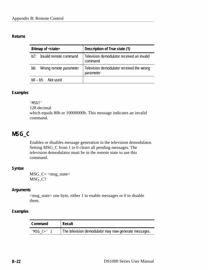
Appendix B: Remote Control
B–22 DS1000 Series User Manual
Bitmap of <state> Description of True state (1)
b7: Invalid remote command Television demodulator received an invalidcommand
b6: Wrong remote parameter Television demodulator received the wrongparameter
b0 – b5: Not used
�����
128 decimalwhich equals 80h or 10000000b. This message indicates an invalidcommand.
MSG_CEnables or disables message generation in the television demodulator.Setting MSG_C from 1 to 0 clears all pending messages. Thetelevision demodulator must be in the remote state to use thiscommand.
MSG_C= <msg_state>MSG_C?
<msg_state> one byte, either 1 to enable messages or 0 to disablethem.
Command Result
������ � The television demodulator may now generate messages.
Returns
Examples
Syntax
Arguments
Examples

Appendix B: Remote Control
DS1000 Series User Manual B–23
PATHPolls the television demodulator to check for status messages. Thetelevision demodulator returns its <Ad><Ads> addresses when there isa message and a null string when there are no messages. Use theMSG? command to get the actual status message. If the messages aredisabled with the MSG_C command, the television demodulator willnot have a message.
For more information on using the PATH command for polling, referto page B–8.
PATH= <Ad><Ars>PATH?
Device address Description
<Ad> Device address, always [0F hex] for the televisiondemodulator.
<Ars> Remote address, calculated on page B–3.
Command Result
������� <Ad><Ars>The television demodulator has a message and is ready tosend it. The <Ad><Ars> addresses are contained in the<data> returned.
Syntax
Returns
Examples

Appendix B: Remote Control
B–24 DS1000 Series User Manual
PRESETSets or requests the settings for one of the 20 programs withoutaffecting the present operation of the television demodulator. Use theRECPRT command to activate a preset program number. Thetelevision demodulator must be in the remote state to use thiscommand.
PRESET=<pres_nr><settings_data>PRESET?
<press_nr> is the program number to set or query. Range 1–20.<settings_data> Refer to the SETT command for a definition of theseparameters.
Command Result
������� �� <settings_data>Returns the program data for number 10.
PWDPuts the television demodulator in the remote state and sets the remoteflag. The front panel is disabled when in the remote state. Use thecommand DISC to enter the local state and clear the remote flag.
PWD=
none
Syntax
Arguments
Examples
Syntax
Arguments

Appendix B: Remote Control
DS1000 Series User Manual B–25
RECPRTSelects and makes active the current program (preset) or requests thecurrent number. The data in <prog_nr> becomes the current setting ofthe television demodulator. This command sets the tuning mode toPROGRAM. This command is allowed only when the remote flag istrue and when TUNING = 4, indicating the PROGRAM mode.
RECPRT= <prog_nr>RECPRT?
<prog_nr> one byte in the range 1 to 20 to indicate the programnumber.
Command Result
��������� 12The program number 12 is the current active program.
Syntax
Arguments
Examples

Appendix B: Remote Control
B–26 DS1000 Series User Manual
REPORT? (Query only)Requests the operating state of the television demodulator. Theresponse is 0 when an active input signal is detected and 2 when nosignal is detected. The television demodulator must be in the remotestate to use this command.
REPORT? <tic_state>
<tic_state> one byte, either 0 to indicate an active signal, or 2 toindicate no input signal.
Command Result
��������� 2The television demodulator does not detect a signal.
SETTSets or requests several operating parameters of the televisiondemodulator. With the SETT command, you can set severalparameters at once instead of using several different commands. SETTcan replace the following commands: FREQ, AFC, AUD_PREF,STRAP, ZCP, BTSC and AUD_OUT. The new settings are effectiveimmediately. The television demodulator must be in the remote stateto use this command.
SETT=<settings_data>SETT?
<setting_data>
Syntax
Arguments
Examples
Syntax
Arguments

Appendix B: Remote Control
DS1000 Series User Manual B–27
Byte offset Setting Range Command/desc
1–2 freqH_val 45 to 860 FREQ
3–4 freqL_val 0 to 999 FREQ
5 status_flags bitmap statusbyte
Set the bit true (1) to enable theassociated function:b7: xb6: ZCP controlb5: audio mode selection bit1b4: audio mode selection bit0b3: audio preference NICAMb2: Sound trap controlb1: AFC controlb0: off–channel frequency
Audio mode, bits b4 & b5:B4 B5 PAL mode NTSC mode0 0 mono1 mono1 0 mono2 mono/SAP0 1 mono1/mono2 stereo1 1 stereo SAP
6–7 ZCP line num-ber
0 to 21 ZCP
8 ZCP position 0 to 4 ZCP
9 BTSC stereonoise
0 to 15 BTSC
10 BTSC SAPnoise
0 to 15 BTSC
Command Result
������� Returns the current settings of the television demodulator.
Examples

Appendix B: Remote Control
B–28 DS1000 Series User Manual
STRAPSets or requests the status of the sound trap. The television demodula-tor must be in the remote state to use this command.
STRAP= <strap_state>STRAP?
<strap_state> Either 1 for On or 0 for Off.
Command Result
������ � Sound trap is on.
Syntax
Arguments
Examples
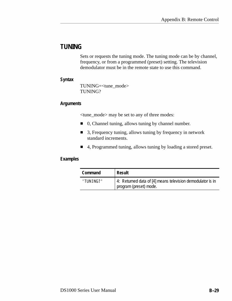
Appendix B: Remote Control
DS1000 Series User Manual B–29
TUNINGSets or requests the tuning mode. The tuning mode can be by channel,frequency, or from a programmed (preset) setting. The televisiondemodulator must be in the remote state to use this command.
TUNING=<tune_mode>TUNING?
<tune_mode> may be set to any of three modes:
� 0, Channel tuning, allows tuning by channel number.
� 3, Frequency tuning, allows tuning by frequency in networkstandard increments.
� 4, Programmed tuning, allows tuning by loading a stored preset.
Command Result
��������� 4: Returned data of [4] means television demodulator is inprogram (preset) mode.
Syntax
Arguments
Examples

Appendix B: Remote Control
B–30 DS1000 Series User Manual
ZCPSets or requests the status of the zero carrier pulse (ZCP). Thetelevision demodulator must be in the remote state to use thiscommand.
ZCP= <zcp_state><zcp_line_no><zcp_position>ZCP?
Byteoffset Arguments Range
1 <zcp_state> 0 for Off, 1 for On
2–3 <zcp_line_no> Sets the line number on which the ZCP isactivated. The range is 0 to 20. The<zcp_line_no> translates to an actual video linenumber as follows:
Line No.0–10:11–21:
PAL6–16319–329
NTSC10–20 (Field 1)10–20 (Field 2)
4 <zcp_position> ZCP position on the selected line. Range is 0 to 4.
Command Result
������ � �� � NTSC:ZCP is active on line 12 (field 2) in position 1.
PAL:ZCP is activate on line 321 in position 1.
Syntax
Arguments
Examples

DS1000 Series User Manual C–1
Appendix C: Service
WARNING. To avoid personal injury or damage to the unit, be sure thatthe power is not supplied to the television demodulator whileperforming the procedures in this section.
This section contains instructions for user service and preventativemaintenance. The only serviceable part is the fuse, which is availableon the rear panel.
There are no user serviceable parts within the unit. Please return it to aTektronix Service Center for service and calibration.
Packaging for ShipmentIf it becomes necessary to ship the television demodulator to aTektronix Service Center, follow these instructions:
1. Write the following on a tag attached to the product: the productowner, complete address and phone number of someone at yourfirm who can be contacted, the product serial number, and adescription of the required service.
2. Package the product in the original packaging materials. If they arenot available, follow these directions:
a. Obtain a carton of corrugated cardboard having insidedimensions at least 6 in (150 mm) greater than thedimensions of the instrument.
b. Surround the product with a protective bag (anti-staticpreferred).
c. Pack dunnage or urethane foam between the product andthe carton. If you use Styrofoam kernels, overfill the boxand compress by closing the lid. There should be 3 inches (75 mm) of tightly packed cushioning on all sidesof the instrument.
3. Seal the carton with shipping tape, an industrial stapler, or both.

Appendix C: Service
C–2 DS1000 Series User Manual
Replacing the Fuse1. Disconnect the power cable from the television demodulator rear
panel.
2. Remove the fuse holder by inserting a suitable instrument on eitherside of the holder and pulling straight out.
3. Remove the old fuse and replace it with a new fuse of the sametype. Use only 250 V, 1.6 A time-delayed fuses.
4. Replace the fuse holder ensuring that the holder clicks back into itssocket.
Cleaning the ExteriorThe instrument should be cleaned often enough to prevent dust anddirt from accumulating. Dirt acts as a thermal insulator, preventingeffective heat dissipation and providing high-resistance electricalleakage paths between conductors or components in a humidenvironment.
CAUTION. To avoid damaging the unit, do not allow water to get insideany enclosed assembly or component. Do not clean any plasticmaterials with benzene, toluene, xylene, acetone, or similar solvents,because they may damage the plastic.
Clean the dust from the outside of the instrument with a soft, dry clothor small brush. A brush is especially useful for removing dust fromaround the buttons and connectors.
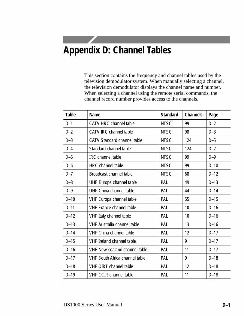
DS1000 Series User Manual D–1
Appendix D: Channel Tables
This section contains the frequency and channel tables used by thetelevision demodulator system. When manually selecting a channel,the television demodulator displays the channel name and number.When selecting a channel using the remote serial commands, thechannel record number provides access to the channels.
Table Name Standard Channels Page
ÁÁÁÁÁÁÁÁ
D–1 ÁÁÁÁÁÁÁÁÁÁÁÁÁÁÁÁÁÁÁÁ
CATV HRC channel table ÁÁÁÁÁÁÁÁÁÁ
NTSC ÁÁÁÁÁÁÁÁ99 ÁÁÁÁ
ÁÁÁÁD–2
ÁÁÁÁÁÁÁÁ
D–2 ÁÁÁÁÁÁÁÁÁÁÁÁÁÁÁÁÁÁÁÁ
CATV IRC channel table ÁÁÁÁÁÁÁÁÁÁ
NTSC ÁÁÁÁÁÁÁÁ98 ÁÁÁÁ
ÁÁÁÁD–3
ÁÁÁÁÁÁÁÁ
D–3 ÁÁÁÁÁÁÁÁÁÁÁÁÁÁÁÁÁÁÁÁ
CATV Standard channel table ÁÁÁÁÁÁÁÁÁÁ
NTSC ÁÁÁÁÁÁÁÁ124 ÁÁÁÁ
ÁÁÁÁD–5
ÁÁÁÁÁÁÁÁ
D–4 ÁÁÁÁÁÁÁÁÁÁÁÁÁÁÁÁÁÁÁÁ
Standard channel table ÁÁÁÁÁÁÁÁÁÁ
NTSC ÁÁÁÁÁÁÁÁ124 ÁÁÁÁ
ÁÁÁÁD–7
ÁÁÁÁÁÁÁÁ
D–5 ÁÁÁÁÁÁÁÁÁÁÁÁÁÁÁÁÁÁÁÁ
IRC channel table ÁÁÁÁÁÁÁÁÁÁ
NTSC ÁÁÁÁÁÁÁÁ99 ÁÁÁÁ
ÁÁÁÁD–9
ÁÁÁÁÁÁÁÁ
D–6 ÁÁÁÁÁÁÁÁÁÁÁÁÁÁÁÁÁÁÁÁ
HRC channel table ÁÁÁÁÁÁÁÁÁÁ
NTSC ÁÁÁÁÁÁÁÁ99 ÁÁÁÁ
ÁÁÁÁD–10
ÁÁÁÁÁÁÁÁ
D–7 ÁÁÁÁÁÁÁÁÁÁÁÁÁÁÁÁÁÁÁÁ
Broadcast channel table ÁÁÁÁÁÁÁÁÁÁ
NTSC ÁÁÁÁÁÁÁÁ68 ÁÁÁÁ
ÁÁÁÁD–12
ÁÁÁÁÁÁÁÁ
D–8 ÁÁÁÁÁÁÁÁÁÁÁÁÁÁÁÁÁÁÁÁ
UHF Europa channel table ÁÁÁÁÁÁÁÁÁÁ
PAL ÁÁÁÁÁÁÁÁ49 ÁÁÁÁ
ÁÁÁÁD–13
ÁÁÁÁÁÁÁÁ
D–9 ÁÁÁÁÁÁÁÁÁÁÁÁÁÁÁÁÁÁÁÁ
UHF China channel table ÁÁÁÁÁÁÁÁÁÁ
PAL ÁÁÁÁÁÁÁÁ44 ÁÁÁÁ
ÁÁÁÁD–14
ÁÁÁÁÁÁÁÁ
D–10ÁÁÁÁÁÁÁÁÁÁÁÁÁÁÁÁÁÁÁÁ
VHF Europa channel tableÁÁÁÁÁÁÁÁÁÁ
PALÁÁÁÁÁÁÁÁ55
ÁÁÁÁÁÁÁÁD–15
ÁÁÁÁÁÁÁÁ
D–11ÁÁÁÁÁÁÁÁÁÁÁÁÁÁÁÁÁÁÁÁ
VHF France channel tableÁÁÁÁÁÁÁÁÁÁ
PALÁÁÁÁÁÁÁÁ10
ÁÁÁÁÁÁÁÁD–16
ÁÁÁÁÁÁÁÁD–12
ÁÁÁÁÁÁÁÁÁÁÁÁÁÁÁÁÁÁÁÁVHF Italy channel table
ÁÁÁÁÁÁÁÁÁÁPAL
ÁÁÁÁÁÁÁÁ10
ÁÁÁÁÁÁÁÁD–16ÁÁÁÁ
ÁÁÁÁD–13ÁÁÁÁÁÁÁÁÁÁÁÁÁÁÁÁÁÁÁÁVHF Australia channel table
ÁÁÁÁÁÁÁÁÁÁPAL
ÁÁÁÁÁÁÁÁ13
ÁÁÁÁÁÁÁÁD–16ÁÁÁÁ
ÁÁÁÁD–14ÁÁÁÁÁÁÁÁÁÁÁÁÁÁÁÁÁÁÁÁVHF China channel table
ÁÁÁÁÁÁÁÁÁÁPAL
ÁÁÁÁÁÁÁÁ12
ÁÁÁÁÁÁÁÁD–17ÁÁÁÁ
ÁÁÁÁÁÁÁÁ
D–15ÁÁÁÁÁÁÁÁÁÁÁÁÁÁÁÁÁÁÁÁÁÁÁÁÁÁÁÁÁÁ
VHF Ireland channel tableÁÁÁÁÁÁÁÁÁÁÁÁÁÁÁ
PALÁÁÁÁÁÁÁÁÁÁÁÁ
9ÁÁÁÁÁÁÁÁÁÁÁÁ
D–17
ÁÁÁÁÁÁÁÁ
D–16 ÁÁÁÁÁÁÁÁÁÁÁÁÁÁÁÁÁÁÁÁ
VHF New Zealand channel table ÁÁÁÁÁÁÁÁÁÁ
PAL ÁÁÁÁÁÁÁÁ11 ÁÁÁÁ
ÁÁÁÁD–17
ÁÁÁÁÁÁÁÁ
D–17 ÁÁÁÁÁÁÁÁÁÁÁÁÁÁÁÁÁÁÁÁ
VHF South Africa channel table ÁÁÁÁÁÁÁÁÁÁ
PAL ÁÁÁÁÁÁÁÁ9 ÁÁÁÁ
ÁÁÁÁD–18
ÁÁÁÁÁÁÁÁ
D–18 ÁÁÁÁÁÁÁÁÁÁÁÁÁÁÁÁÁÁÁÁ
VHF OIRT channel table ÁÁÁÁÁÁÁÁÁÁ
PAL ÁÁÁÁÁÁÁÁ12 ÁÁÁÁ
ÁÁÁÁD–18
ÁÁÁÁÁÁÁÁ
D–19 ÁÁÁÁÁÁÁÁÁÁÁÁÁÁÁÁÁÁÁÁ
VHF CCIR channel table ÁÁÁÁÁÁÁÁÁÁ
PAL ÁÁÁÁÁÁÁÁ11 ÁÁÁÁ
ÁÁÁÁD–18

Appendix D: Channel Tables
D–2 DS1000 Series User Manual
Table D–1: CATV HRC channel table
Rec Chan FreqNo. No. (MHz)
Rec Chan FreqNo. No. (MHz)
Rec Chan FreqNo. No. (MHz)
0 1 72.00
1 2 54.00
2 3 60.00
3 4 66.00
4 5 78.00
5 6 84.00
6 7 174.00
7 8 180.00
8 9 186.00
9 10 192.00
10 11 198.00
11 12 204.00
12 13 210.00
13 14 120.00
14 15 126.00
15 16 132.00
16 17 138.00
17 18 144.00
18 19 150.00
19 20 156.00
20 21 162.00
21 22 168.00
22 23 216.00
23 24 222.00
24 25 228.00
25 26 234.00
26 27 240.00
27 28 246.00
28 29 252.00
29 30 258.00
30 31 264.00
31 32 270.00
32 33 276.00
33 34 282.00
34 35 288.00
35 36 294.00
36 37 300.00
37 38 306.00
38 39 312.00
39 40 318.00
40 41 324.00
41 42 330.00
42 43 336.00
43 44 342.00
44 45 348.00
45 46 354.00
46 47 360.00
47 48 366.00
48 49 372.00
49 50 378.00
50 51 384.00
51 52 390.00
52 53 396.00
53 54 402.00
54 55 408.00
55 56 414.00
56 57 420.00
57 58 426.00
58 59 432.00
59 60 438.00
60 61 444.00
61 62 450.00
62 63 456.00
63 64 462.00
64 65 468.00
65 66 474.00
66 67 480.00
67 68 486.00
68 69 492.00
69 70 498.00
70 71 504.00
71 72 510.00
72 73 516.00
73 74 522.00
74 75 528.00

Appendix D: Channel Tables
DS1000 Series User Manual D–3
Table D–1: CATV HRC channel table (cont.)
Rec Chan FreqNo. No. (MHz)
Rec Chan FreqNo. No. (MHz)
Rec Chan FreqNo. No. (MHz)
75 76 534.00
76 77 540.00
77 78 546.00
78 79 552.00
79 80 558.00
80 81 564.00
81 82 570.00
82 83 576.00
83 84 582.00
84 85 588.00
85 86 594.00
86 87 600.00
87 88 606.00
88 89 612.00
89 90 618.00
90 91 624.00
91 92 630.00
92 93 636.00
93 94 642.00
94 95 90.00
95 96 96.00
96 97 102.00
97 98 108.00
98 99 114.00
Table D–2: CATV IRC channel table
Rec Chan FreqNo. No. (MHz)
Rec Chan FreqNo. No. (MHz)
Rec Chan FreqNo. No. (MHz)
0 2 55.25
1 3 61.25
2 4 67.25
3 5 79.25
4 6 85.25
5 7 175.25
6 8 181.25
7 9 187.25
8 10 193.25
9 11 199.25
10 12 205.25
11 13 211.25
12 14 121.25
13 15 127.25
14 16 133.25
15 17 139.25
16 18 145.25
17 19 151.25
18 20 157.25
19 21 163.25
20 22 169.25
21 23 217.25
22 24 223.25
23 25 229.25
24 26 235.25
25 27 241.25
26 28 247.25
27 29 253.25
28 30 259.25
29 31 265.25
30 32 271.25
31 33 277.25
32 34 283.25
33 35 289.25
34 36 295.25
35 37 301.25

Appendix D: Channel Tables
D–4 DS1000 Series User Manual
Table D–2: CATV IRC channel table (cont.)
Rec Chan FreqNo. No. (MHz)
Rec Chan FreqNo. No. (MHz)
Rec Chan FreqNo. No. (MHz)
36 38 307.25
37 39 313.25
38 40 319.25
39 41 325.25
40 42 331.25
41 43 337.25
42 44 343.25
43 45 349.25
44 46 355.25
45 47 361.25
46 48 367.25
47 49 373.25
48 50 379.25
49 51 385.25
50 52 391.25
51 53 397.25
52 54 403.25
53 55 409.25
54 56 415.25
55 57 421.25
56 58 427.25
57 59 433.25
58 60 439.25
59 61 445.25
60 62 451.25
61 63 457.25
62 64 463.25
63 65 469.25
64 66 475.25
65 67 481.25
66 68 487.25
67 69 493.25
68 70 499.25
69 71 505.25
70 72 511.25
71 73 517.25
72 74 523.25
73 75 529.25
74 76 535.25
75 77 541.25
76 78 547.25
77 79 553.25
78 80 559.25
79 81 565.25
80 82 571.25
81 83 577.25
82 84 583.25
83 85 589.25
84 86 595.25
85 87 601.25
86 88 607.25
87 89 613.25
88 90 619.25
89 91 625.25
90 92 631.25
91 93 637.25
92 94 643.25
93 95 91.25
94 96 97.25
95 97 103.25
96 98 109.25
97 99 115.25

Appendix D: Channel Tables
DS1000 Series User Manual D–5
Table D–3: CATV standard channel table
Rec Chan FreqNo. No. (MHz)
Rec Chan FreqNo. No. (MHz)
Rec Chan FreqNo. No. (MHz)
0 2 55.25
1 3 61.25
2 4 67.25
3 5 77.25
4 6 83.25
5 7 175.25
6 8 181.25
7 9 187.25
8 10 193.25
9 11 199.25
10 12 205.25
11 13 211.25
12 14 121.25
13 15 127.25
14 16 133.25
15 17 139.25
16 18 145.25
17 19 151.25
18 20 157.25
19 21 163.25
20 22 169.25
21 23 217.25
22 24 223.25
23 25 229.25
24 26 235.25
25 27 241.25
26 28 247.25
27 29 253.25
28 30 259.25
29 31 265.25
30 32 271.25
31 33 277.25
32 34 283.25
33 35 289.25
34 36 295.25
35 37 301.25
36 38 307.25
37 39 313.25
38 40 319.25
39 41 325.25
40 42 331.25
41 43 337.25
42 44 343.25
43 45 349.25
44 46 355.25
45 47 361.25
46 48 367.25
47 49 373.25
48 50 379.25
49 51 385.25
50 52 391.25
51 53 397.25
52 54 403.25
53 55 409.25
54 56 415.25
55 57 421.25
56 58 427.25
57 59 433.25
58 60 439.25
59 61 445.25
60 62 451.25
61 63 457.25
62 64 463.25
63 65 469.25
64 66 475.25
65 67 481.25
66 68 487.25
67 69 493.25
68 70 499.25
69 71 505.25
70 72 511.25
71 73 517.25
72 74 523.25
73 75 529.25
74 76 535.25

Appendix D: Channel Tables
D–6 DS1000 Series User Manual
Table D–3: CATV standard channel table (cont.)
Rec Chan FreqNo. No. (MHz)
Rec Chan FreqNo. No. (MHz)
Rec Chan FreqNo. No. (MHz)
75 77 541.25
76 78 547.25
77 79 553.25
78 80 559.25
79 81 565.25
80 82 571.25
81 83 577.25
82 84 583.25
83 85 589.25
84 86 595.25
85 87 601.25
86 88 607.25
87 89 613.25
88 90 619.25
89 91 625.25
90 92 631.25
91 93 637.25
92 94 643.25
93 95 91.25
94 96 97.25
95 97 103.25
96 98 109.25
97 99 115.25
98 100 649.25
99 101 655.25
100 102 661.25
101 103 667.25
102 104 673.25
103 105 679.25
104 106 685.25
105 107 691.25
106 108 697.25
107 109 703.25
108 110 709.25
109 111 715.25
110 112 721.25
111 113 727.25
112 114 733.25
113 115 739.25
114 116 745.25
115 117 751.25
116 118 757.25
117 119 763.25
118 120 769.25
119 121 775.25
120 122 781.25
121 123 787.25
122 124 793.25
123 125 799.25

Appendix D: Channel Tables
DS1000 Series User Manual D–7
Table D–4: Standard channel table
Rec Chan FreqNo. No. (MHz)
Rec Chan FreqNo. No. (MHz)
Rec Chan FreqNo. No. (MHz)
0 2 55.25
1 3 61.25
2 4 67.25
3 5 77.25
4 6 83.25
5 95 91.25
6 96 97.25
7 97 103.25
8 98 109.25
9 99 115.25
10 14 121.26
11 15 127.26
12 16 133.26
13 17 139.25
14 18 145.25
15 19 151.25
16 20 157.25
17 21 163.25
18 22 169.25
19 7 175.25
20 8 181.25
21 9 187.25
22 10 193.25
23 11 199.25
24 12 205.25
25 13 211.25
26 23 217.25
27 24 223.25
28 25 229.26
29 26 235.26
30 27 241.26
31 28 247.26
32 29 253.26
33 30 259.26
34 31 265.26
35 32 271.26
36 33 277.26
37 34 283.26
38 35 289.26
39 36 295.26
40 37 301.26
41 38 307.26
42 39 313.26
43 40 319.26
44 41 325.26
45 42 331.27
46 43 337.26
47 44 343.26
48 45 349.26
49 46 355.26
50 47 361.26
51 48 367.26
52 49 373.26
53 50 379.26
54 51 385.26
55 52 391.26
56 53 397.26
57 54 403.25
58 55 409.25
59 56 415.25
60 57 421.25
61 58 427.25
62 59 433.25
63 60 439.25
64 61 445.25
65 62 451.25
66 63 457.25
67 64 463.25
68 65 469.25
69 66 475.25
70 67 481.25
71 68 487.25
72 69 493.25
73 70 499.25
74 71 505.25

Appendix D: Channel Tables
D–8 DS1000 Series User Manual
Table D–4: Standard channel table (cont.)
Rec Chan FreqNo. No. (MHz)
Rec Chan FreqNo. No. (MHz)
Rec Chan FreqNo. No. (MHz)
75 72 511.25
76 73 517.25
77 74 523.25
78 75 529.25
79 76 535.25
80 77 541.25
81 78 547.25
82 79 553.25
83 80 559.25
84 81 565.25
85 82 571.25
86 83 577.25
87 84 583.25
88 85 589.25
89 86 595.25
90 87 601.25
91 88 607.25
92 89 613.25
93 90 619.25
94 91 625.25
95 92 631.25
96 93 637.25
97 94 643.25
98 100 649.25
99 101 655.25
100 102 661.25
101 103 667.25
102 104 673.25
103 105 679.25
104 106 685.25
105 107 691.25
106 108 697.25
107 109 703.25
108 110 709.25
109 111 715.25
110 112 721.25
111 113 727.25
112 114 733.25
113 115 739.25
114 116 745.25
115 117 751.25
116 118 757.25
117 119 763.25
118 120 769.25
119 121 755.25
120 122 781.25
121 123 787.25
122 124 793.25
123 125 799.25

Appendix D: Channel Tables
DS1000 Series User Manual D–9
Table D–5: IRC channel table
Rec Chan FreqNo. No. (MHz)
Rec Chan FreqNo. No. (MHz)
Rec Chan FreqNo. No. (MHz)
0 2 55.25
1 3 61.25
2 4 67.25
3 1 73.25
4 5 79.25
5 6 85.25
6 95 91.25
7 96 97.25
8 97 103.25
9 98 109.25
10 99 115.26
11 14 121.26
12 15 127.26
13 16 133.25
14 17 139.25
15 18 145.25
16 19 151.25
17 20 157.25
18 21 163.25
19 22 169.25
20 7 175.25
21 8 181.25
22 9 187.25
23 10 193.25
24 11 199.25
25 12 205.25
26 13 211.25
27 23 217.25
28 24 223.26
29 25 229.26
30 26 235.26
31 27 241.26
32 28 247.26
33 29 253.26
34 30 259.25
35 31 265.25
36 32 271.25
37 33 277.25
38 34 283.25
39 35 289.25
40 36 295.25
41 37 301.25
42 38 307.25
43 39 313.25
44 40 319.25
45 41 325.25
46 42 331.25
47 43 337.25
48 44 343.25
49 45 349.25
50 46 355.25
51 47 361.25
52 48 367.25
53 49 373.25
54 50 379.25
55 51 385.25
56 52 391.25
57 53 397.25
58 54 403.25
59 55 409.25
60 56 415.25
61 57 421.25
62 58 427.25
63 69 433.25
64 60 439.25
65 61 445.25
66 62 451.25
67 63 457.25
68 64 463.25
69 65 469.25
70 66 475.25
71 67 481.25
72 68 487.25
73 69 493.25
74 70 499.25

Appendix D: Channel Tables
D–10 DS1000 Series User Manual
Table D–5: IRC channel table (cont.)
Rec Chan FreqNo. No. (MHz)
Rec Chan FreqNo. No. (MHz)
Rec Chan FreqNo. No. (MHz)
75 71 505.25
76 72 511.25
77 73 517.25
78 74 523.25
79 75 529.25
80 76 535.25
81 77 541.25
82 78 547.25
83 79 553.25
84 80 559.25
85 81 565.25
86 82 571.25
87 83 577.25
88 84 583.25
89 85 589.25
90 86 595.25
91 87 601.25
92 88 607.25
93 89 613.25
94 90 619.25
95 92 625.25
96 92 631.25
97 93 637.25
98 94 643.25
Table D–6: HRC channel table
Rec Chan FreqNo. No. (MHz)
Rec Chan FreqNo. No. (MHz)
Rec Chan FreqNo. No. (MHz)
0 2 54.00
1 3 60.00
2 4 66.00
3 1 72.00
4 5 78.00
5 6 84.00
6 95 90.00
7 96 96.00
8 97 102.00
9 98 108.00
10 99 114.00
11 14 120.00
12 15 126.00
13 16 132.00
14 17 138.00
15 18 144.00
16 19 150.00
17 20 156.00
18 21 162.00
19 22 168.00
20 7 174.00
21 8 180.00
22 9 186.00
23 10 192.00
24 11 198.00
25 12 204.00
26 13 210.00
27 23 216.00
28 24 222.00
29 25 228.00
30 26 234.00
31 27 240.00
32 28 246.00
33 29 252.00
34 30 258.00
35 31 264.00
36 32 270.00
37 33 276.00
38 34 282.00

Appendix D: Channel Tables
DS1000 Series User Manual D–11
Table D–6: HRC channel table (cont.)
Rec Chan FreqNo. No. (MHz)
Rec Chan FreqNo. No. (MHz)
Rec Chan FreqNo. No. (MHz)
39 35 288.00
40 36 294.00
41 37 300.00
42 38 306.00
43 39 312.00
44 40 318.00
45 41 324.00
46 42 330.00
47 43 336.00
48 44 342.00
49 45 348.00
50 46 354.00
51 47 360.00
52 48 366.00
53 49 372.00
54 50 378.00
55 51 384.00
56 52 390.00
57 53 396.00
58 54 402.00
59 55 408.00
60 56 414.00
61 57 420.00
62 58 426.00
63 59 432.00
64 60 438.00
65 61 444.00
66 62 450.00
67 63 456.00
68 64 462.00
69 65 468.00
70 66 474.00
71 67 480.00
72 68 486.00
73 69 492.00
74 70 498.00
75 71 504.00
76 72 510.00
77 73 516.00
78 74 522.00
79 75 528.00
80 76 534.00
81 77 540.00
82 78 546.00
83 79 552.00
84 80 558.00
85 81 564.00
86 82 570.00
87 83 576.00
88 84 582.00
89 85 588.00
90 86 594.00
91 87 600.00
92 88 606.00
93 89 612.00
94 90 618.00
95 91 624.00
96 92 630.00
97 93 636.00
98 94 642.00

Appendix D: Channel Tables
D–12 DS1000 Series User Manual
Table D–7: Broadcast channel table
Rec Chan FreqNo. No. (MHz)
Rec Chan FreqNo. No. (MHz)
Rec Chan FreqNo. No. (MHz)
0 2 55.25
1 3 61.25
2 4 67.25
3 5 77.25
4 6 83.25
5 7 175.25
6 8 181.25
7 9 187.25
8 10 193.25
9 11 199.25
10 12 205.25
11 13 211.25
12 14 471.25
13 15 477.25
14 16 483.25
15 17 489.25
16 18 495.25
17 19 501.25
18 20 507.25
19 21 513.25
20 22 519.25
21 23 525.25
22 24 531.25
23 25 537.25
24 26 543.25
25 27 549.25
26 28 555.25
27 29 561.25
28 30 567.25
29 31 573.25
30 32 579.25
31 33 585.25
32 34 591.25
33 35 597.25
34 36 603.25
35 37 609.25
36 38 615.25
37 39 621.25
38 40 627.25
39 41 633.25
40 42 639.25
41 43 645.25
42 44 651.25
43 45 657.25
44 46 663.25
45 47 669.25
46 48 675.25
47 49 681.25
48 50 687.25
49 51 693.25
50 52 699.25
51 53 705.25
52 54 711.25
53 55 717.25
54 56 723.25
55 57 729.25
56 58 735.25
57 59 741.25
58 60 747.25
59 61 753.25
60 62 759.25
61 63 765.25
62 64 771.25
63 65 777.25
64 66 783.25
65 67 789.25
66 68 795.25
67 69 801.25

Appendix D: Channel Tables
DS1000 Series User Manual D–13
Table D–8: UHF Europa channel table
Rec Chan FreqNo. No. (MHz)
Rec Chan FreqNo. No. (MHz)
Rec Chan FreqNo. No. (MHz)
0 21 471.25
1 22 479.25
2 23 487.25
3 24 495.25
4 25 503.25
5 26 511.25
6 27 519.25
7 28 527.25
8 29 535.25
9 30 543.25
10 31 551.25
11 32 559.25
12 33 567.25
13 34 575.25
14 35 583.25
15 36 591.25
16 37 599.25
17 38 607.25
18 39 615.25
19 40 623.25
20 41 631.25
21 42 639.25
22 43 647.25
23 44 655.25
24 45 663.25
25 46 671.25
26 47 679.25
27 48 687.25
28 49 695.25
29 50 703.25
30 51 711.25
31 52 719.25
32 53 727.25
33 54 735.25
34 55 743.25
35 56 751.25
36 57 759.25
37 58 767.25
38 59 775.25
39 60 783.25
40 61 791.25
41 62 799.25
42 63 807.25
43 64 815.25
44 65 823.25
45 66 831.25
46 67 839.25
47 68 847.25
48 69 855.25

Appendix D: Channel Tables
D–14 DS1000 Series User Manual
Table D–9: UHF China channel table
Rec Chan FreqNo. No. (MHz)
Rec Chan FreqNo. No. (MHz)
Rec Chan FreqNo. No. (MHz)
0 13 471.25
1 14 479.25
2 15 487.25
3 16 495.25
4 17 503.25
5 18 511.25
6 19 519.25
7 20 527.25
8 21 535.25
9 22 543.25
10 23 551.25
11 24 559.25
12 25 607.25
13 26 615.25
14 27 623.25
15 28 631.25
16 29 639.25
17 30 647.25
18 31 655.25
19 32 663.25
20 33 671.25
21 34 679.25
22 35 687.25
23 36 695.25
24 37 703.25
25 38 711.25
26 39 719.25
27 40 727.25
28 41 735.25
29 42 743.25
30 43 751.25
31 44 759.25
32 45 767.25
33 46 775.25
34 47 783.25
35 48 791.25
36 49 799.25
37 50 807.25
38 51 815.25
39 52 823.25
40 53 831.25
41 54 839.25
42 55 847.25
43 56 855.25
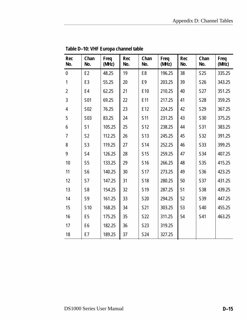
Appendix D: Channel Tables
DS1000 Series User Manual D–15
Table D–10: VHF Europa channel table
Rec Chan FreqNo. No. (MHz)
Rec Chan FreqNo. No. (MHz)
Rec Chan FreqNo. No. (MHz)
0 E2 48.25
1 E3 55.25
2 E4 62.25
3 S01 69.25
4 S02 76.25
5 S03 83.25
6 S1 105.25
7 S2 112.25
8 S3 119.25
9 S4 126.25
10 S5 133.25
11 S6 140.25
12 S7 147.25
13 S8 154.25
14 S9 161.25
15 S10 168.25
16 E5 175.25
17 E6 182.25
18 E7 189.25
19 E8 196.25
20 E9 203.25
21 E10 210.25
22 E11 217.25
23 E12 224.25
24 S11 231.25
25 S12 238.25
26 S13 245.25
27 S14 252.25
28 S15 259.25
29 S16 266.25
30 S17 273.25
31 S18 280.25
32 S19 287.25
33 S20 294.25
34 S21 303.25
35 S22 311.25
36 S23 319.25
37 S24 327.25
38 S25 335.25
39 S26 343.25
40 S27 351.25
41 S28 359.25
42 S29 367.25
43 S30 375.25
44 S31 383.25
45 S32 391.25
46 S33 399.25
47 S34 407.25
48 S35 415.25
49 S36 423.25
50 S37 431.25
51 S38 439.25
52 S39 447.25
53 S40 455.25
54 S41 463.25

Appendix D: Channel Tables
D–16 DS1000 Series User Manual
Table D–11: VHF France channel table
Rec Chan FreqNo. No. (MHz)
Rec Chan FreqNo. No. (MHz)
Rec Chan FreqNo. No. (MHz)
0 A 47.75
1 B 55.75
2 C1 60.50
3 C 63.55
4 1 176.00
5 2 184.00
6 3 192.00
7 4 200.00
8 5 208.00
9 6 216.00
Table D–12: VHF Italy channel table
Rec Chan FreqNo. No. (MHz)
Rec Chan FreqNo. No. (MHz)
Rec Chan FreqNo. No. (MHz)
0 A 53.75
1 B 62.25
2 C 82.25
3 D 175.25
4 E 183.75
5 F 192.25
6 G 201.25
7 H 210.25
8 H1 217.25
9 H2 224.25
Table D–13: VHF Australia channel table
Rec Chan FreqNo. No. (MHz)
Rec Chan FreqNo. No. (MHz)
Rec Chan FreqNo. No. (MHz)
0 0 46.25
1 1 57.25
2 2 64.25
3 3 86.25
4 4 95.25
5 5 102.25
6 6A 138.25
7 6 175.25
8 7 182.25
9 8 189.25
10 9 196.25
11 10 209.25
12 11 216.25

Appendix D: Channel Tables
DS1000 Series User Manual D–17
Table D–14: VHF China channel table
Rec Chan FreqNo. No. (MHz)
Rec Chan FreqNo. No. (MHz)
Rec Chan FreqNo. No. (MHz)
0 1 47.75
1 2 57.75
2 3 65.75
3 4 77.25
4 5 85.25
5 6 168.25
6 7A 176.25
7 8 184.25
8 9 192.25
9 10 200.25
10 11 208.25
11 112 216.25
Table D–15: VHF Ireland channel table
Rec Chan FreqNo. No. (MHz)
Rec Chan FreqNo. No. (MHz)
Rec Chan FreqNo. No. (MHz)
0 A 45.75
1 B 53.75
2 C 61.75
3 D 175.25
4 E 183.25
5 F 191.25
6 G 199.25
7 H 207.25
8 J 215.25
Table D–16: VHF New Zealand channel table
Rec Chan FreqNo. No. (MHz)
Rec Chan FreqNo. No. (MHz)
Rec Chan FreqNo. No. (MHz)
0 1 45.25
1 2 55.25
2 3 62.25
3 4 175.25
4 5 182.25
5 6 189.25
6 7A 196.25
7 8 203.25
8 9 210.25
9 10 217.25
10 11 224.25

Appendix D: Channel Tables
D–18 DS1000 Series User Manual
Table D–17: VHF South Africa channel table
Rec Chan FreqNo. No. (MHz)
Rec Chan FreqNo. No. (MHz)
Rec Chan FreqNo. No. (MHz)
0 4 175.25
1 5 183.25
2 6 191.25
3 7 199.25
4 8 207.25
5 9 215.25
6 10 223.25
7 11 231.25
8 13 247.43
Table D–18: VHF OIRT channel table
Rec Chan FreqNo. No. (MHz)
Rec Chan FreqNo. No. (MHz)
Rec Chan FreqNo. No. (MHz)
0 1 49.75
1 2 59.25
2 3 77.25
3 4 85.25
4 5 93.25
5 6 175.25
6 7A 183.25
7 8 191.25
8 9 199.25
9 10 207.25
10 11 215.25
11 112 223.25
Table D–19: VHF CCIR channel table
Rec Chan FreqNo. No. (MHz)
Rec Chan FreqNo. No. (MHz)
Rec Chan FreqNo. No. (MHz)
0 2 48.25
1 3 55.25
2 4 62.25
3 5 175.25
4 6 182.25
5 7 189.25
6 8A 196.25
7 9 203.25
8 10 210.25
9 11 217.25
10 12 224.25

DS1000 Series User Manual E–1
Appendix E: Factory Default Settings
This section lists the factory default settings for user definablesettings. All programs (presets) are set the same, so only the defaultsetting for one program is shown.
Table E–1: Program default settings
Program item NTSC system PAL systemÁÁÁÁÁÁÁÁÁÁÁÁÁÁÁÁÁÁFrequency Table
ÁÁÁÁÁÁÁÁÁÁÁÁBroadcast
ÁÁÁÁÁÁÁÁÁÁÁÁÁÁUHF EuropaÁÁÁÁÁÁÁÁÁ
ÁÁÁÁÁÁÁÁÁÁÁÁÁÁÁÁÁÁ
Channel NumberÁÁÁÁÁÁÁÁÁÁÁÁÁÁÁÁÁÁ
38ÁÁÁÁÁÁÁÁÁÁÁÁÁÁÁÁÁÁÁÁÁ
39
ÁÁÁÁÁÁÁÁÁÁÁÁÁÁÁÁÁÁ
Frequency ÁÁÁÁÁÁÁÁÁÁÁÁ
615.25 MHz ÁÁÁÁÁÁÁÁÁÁÁÁÁÁ
615.25 MHz
ÁÁÁÁÁÁÁÁÁÁÁÁÁÁÁÁÁÁ
ZCP State ÁÁÁÁÁÁÁÁÁÁÁÁ
Off ÁÁÁÁÁÁÁÁÁÁÁÁÁÁ
Off
ÁÁÁÁÁÁÁÁÁÁÁÁÁÁÁÁÁÁ
ZCP Line Number ÁÁÁÁÁÁÁÁÁÁÁÁ
16 (F1) ÁÁÁÁÁÁÁÁÁÁÁÁÁÁ
13
ÁÁÁÁÁÁÁÁÁÁÁÁÁÁÁÁÁÁ
ZCP Position ÁÁÁÁÁÁÁÁÁÁÁÁ
1 ÁÁÁÁÁÁÁÁÁÁÁÁÁÁ
1ÁÁÁÁÁÁÁÁÁÁÁÁÁÁÁÁÁÁ
Audio Preference ÁÁÁÁÁÁÁÁÁÁÁÁ
BTSC ÁÁÁÁÁÁÁÁÁÁÁÁÁÁ
NICAMÁÁÁÁÁÁÁÁÁÁÁÁÁÁÁÁÁÁ
AFC StateÁÁÁÁÁÁÁÁÁÁÁÁ
OffÁÁÁÁÁÁÁÁÁÁÁÁÁÁ
OffÁÁÁÁÁÁÁÁÁÁÁÁÁÁÁÁÁÁSound Trap State
ÁÁÁÁÁÁÁÁÁÁÁÁOn
ÁÁÁÁÁÁÁÁÁÁÁÁÁÁOnÁÁÁÁÁÁÁÁÁ
ÁÁÁÁÁÁÁÁÁÁÁÁÁÁÁÁÁÁ
Audio Output ModeÁÁÁÁÁÁÁÁÁÁÁÁÁÁÁÁÁÁ
StereoÁÁÁÁÁÁÁÁÁÁÁÁÁÁÁÁÁÁÁÁÁ
Stereo
ÁÁÁÁÁÁÁÁÁÁÁÁÁÁÁÁÁÁ
BTSC Stereo Noise ÁÁÁÁÁÁÁÁÁÁÁÁ
8 ÁÁÁÁÁÁÁÁÁÁÁÁÁÁ
–
ÁÁÁÁÁÁÁÁÁÁÁÁÁÁÁÁÁÁ
BTSC SAP Noise ÁÁÁÁÁÁÁÁÁÁÁÁ
8 ÁÁÁÁÁÁÁÁÁÁÁÁÁÁ
–

Appendix E: Factory Default Settings
E–2 DS1000 Series User Manual
Table E–2: System default settings
Item Default setting
ÁÁÁÁÁÁÁÁÁÁÁÁÁÁÁÁÁÁÁÁ
Active Program ÁÁÁÁÁÁÁÁÁÁÁÁÁÁÁÁÁÁÁÁ
1
ÁÁÁÁÁÁÁÁÁÁÁÁÁÁÁÁÁÁÁÁ
Position Message (IDN command) ÁÁÁÁÁÁÁÁÁÁÁÁÁÁÁÁÁÁÁÁ
Set to ASCII space characterÁÁÁÁÁÁÁÁÁÁÁÁÁÁÁÁÁÁÁÁÁÁÁÁÁÁÁÁÁÁ
Manual Frequency Response(All frequency steps)
ÁÁÁÁÁÁÁÁÁÁÁÁÁÁÁÁÁÁÁÁÁÁÁÁÁÁÁÁÁÁ
0
User Defined Channel Table(All channels)
200.00 MHz
Serial Mode RS232
ÁÁÁÁÁÁÁÁÁÁÁÁÁÁÁÁÁÁÁÁ
Unit Address ÁÁÁÁÁÁÁÁÁÁÁÁÁÁÁÁÁÁÁÁ
32
RS232 Handshake Status Enabled
RS485 Termination Terminated

Glossary


DS1000 Series User Manual Glossary–1
Glossary
BandwidthThe range of frequencies over which signal amplitude remainsconstant (within some limit) as it is passed through a system.
BasebandThe composite video signal before it modulates the picture carrier.Composite video that is distributed throughout a studio and is usedfor recording is at baseband.
Broad PulsesThe vertical synchronizing pulses in the center of the verticalinterval. These pulses are long enough to be distinguished from allothers and are the part of the signal actually detected by verticalsync separators.
BurstA small reference packet of the subcarrier sine wave sent on everyline of video. Since the carrier is suppressed, this phase andfrequency reference is required for synchronous demodulation ofthe color difference signals in the receiver.
B-YOne of the color difference signals used in the NTSC and PALsystems. It is obtained by subtracting luminance (Y) from the bluecamera signal (B).
ChrominanceThe color information in a television picture.
Chrominance SignalThe high-frequency portion of the video signal, that is obtained byquadrature amplitude modulation of a 4.43 MHz (PAL) or3.58 MHz (NTSC) subcarrier with R-Y and B-Y information.
Composite VideoA single video signal containing all of the necessary information toreproduce a color picture.
Glossary
Glossary–2 DS1000 Series User Manual
CWContinuous Wave. A separate subcarrier sine wave used forsynchronization of chrominance information.
dB (Decibel)A logarithmic unit used to describe signal ratios. For voltages, dB = 20 Log10 (V1/V2).
DemodulatorIn general, any device that recovers the original signal after it hasmodulated a high frequency carrier. In television, it refers to one ofthe following descriptions:
1. An instrument, such as the Tektronix DS1001, which takesvideo in its transmitted form (modulated onto the picturecarrier) and converts it to baseband.
2. The circuits that recover R-Y and B-Y from the compositesignal.
FieldHalf of the video lines required to produce a full video frame. Ininterlaced scan systems, such as NTSC and PAL, the informationfor one video frame is divided into two fields. Two vertical scansoverlay the two fields to produce the complete frame. In thecomplete frame, adjacent video lines in the picture are fromalternate fields.
FMFrequency Modulation. The process by which the frequency of acarrier signal is varied in proportion to the modulating signal, suchas an audio signal. In the NTSC and PAL television systems, audioinformation is transmitted using FM.
FrameContains all the information required for a complete picture. Forinterlaced scan systems, there are two fields in a frame.
Harmonic DistortionSignal distortion caused by non-linearities in a system. Systemnon-linearities produce multiples of a single frequency signalapplied to the the system. Harmonic distortion is evident when apure sine wave applied to a system produces harmonic content atmultiples of the sine wave frequency at the output.

Glossary
DS1000 Series User Manual Glossary–3
HumThe undesirable coupling of the 50 Hz (PAL) or 60 Hz (NTSC)power sine wave into other electrical circuits.
Intercarrier SoundA method used to recover audio information. Sound is separatedfrom video by beating the sound carrier against the video carrier,producing a 4.5 MHz (NTSC) or 5.5 MHz (PAL) IF that containsthe sound information.
IREA unit equal to 1/140 of the peak-to-peak amplitude of the videosignal, which is typically one volt. The 0 IRE point is at theblanking level, with the sync tip at –40 IRE and the whiteextending to +100 IRE. IRE stands for Institute of RadioEngineers, the organization that defined the unit.
Linear DistortionDistortions that are independent of signal amplitude.
LuminanceThe signal (Y) that represents brightness, or the amount of light inthe picture. This is the only signal required for black and whitepictures. For color systems, it is obtained as a weighted sum(Y = 0.3R + 0.59G + 0.11B) of the R, G, and B signals.
ModulatedWhen referring to television test signals, this term implies thatchrominance information is present. (For example, a modulatedramp has subcarrier on each step.)
ModulationA process that moves information around in the frequency domainin order to facilitate transmission or frequency-domain multiplex-ing.
Non-Linear DistortionSignal distortion that does not increase at the same rate as thesignal amplitude.
NTSCNational Television System Committee. The organization thatdeveloped the television standard currently in use in the United

Glossary
Glossary–4 DS1000 Series User Manual
States, Canada, and Japan. Now, NTSC is generally used to refer tothat standard.
PALPhase Alternate Line. One of the television systems used in Europeand many other parts of the world. The phase of one of the colordifference signals alternates from line to line to help cancel outphase errors.
Quadrature AMA process that allows two signals to modulate a single carrierfrequency. Two signals amplitude modulate carrier signals with thesame frequency but with a phase difference of 90 degrees (hencethe term Quadrature). The two resultant signals are added togetherbefore transmission. Both signals are recovered at the receiver bydemodulating them 90 degrees apart.
Quadrature DistortionDistortion resulting from the asymmetry of sidebands used investigial sideband television transmission. Quadrature distortionappears when using envelope detection but can be eliminated byusing a synchronous demodulator.
RFRadio Frequency. In television applications, the television signalafter the picture carrier modulation process.
RGBRed, Green and Blue. The three primary colors used in colortelevision’s additive color reproduction system. These are the threecolor components generated by the camera and used by the picturemonitor to produce a picture.
SubcarrierThe high-frequency signal used for quadrature amplitudemodulation of the color difference signals. The subcarrierfrequency is 3,579,545 Hz (NTSC) or 4,433,618.75 Hz (PAL).
Synchronous DetectionA demodulation process in which the original signal is recoveredby multiplying the modulated signal with the output of asynchronous oscillator locked to the carrier.

Glossary
DS1000 Series User Manual Glossary–5
TerminationAn impedance at the end of a transmission line that matches theimpedance of the source and of the line itself. Proper terminationprevents amplitude errors and reflections. Video systems use 75 �
transmission lines, so a 75 � terminator must be at the end of anysignal path. A receiving device connected to the transmission linemay provide the necessary termination.
Vertical IntervalThe synchronizing information that appears between fields andtells the picture monitor to go back to the top of the screen to beginanother vertical scan.
YAbbreviation for luminance.
Zero Carrier Reference Pulse (ZCP)A pulse in the vertical interval which is produced by thedemodulator to provide a reference for evaluating the depth ofmodulation.

Glossary
Glossary–6 DS1000 Series User Manual

Index


DS1000 Series User Manual Index–1
Index
AAccessories
optional, 1–3standard, 1–3
AddressRS485 addresses, B–3setting for RS485 serial commu-
nication, 3–8Adjust, frequency response, 3–10AFC
remote command, B–13selecting mode in program, 3–6
Applying power, 1–4, 2–4AUD_OUT, remote command,
B–14AUD_PREF, remote command,
B–15Audio
AUD_OUT remote command,B–14
AUD_PREF remote command,B–15
BTSC remote command, B–16CHANNEL remote command,
B–17input selection, 3–6selecting mode in program, 3–6setting noise threshold, 3–7specifications, A–3
Audio outputsdescription, 2–4left, 2–4status display, 2–6
BBaud rate, B–2
BTSCaudio selection for NTSC, 3–6remote command, B–16
Buttonsarrow, 2–2CONFIG, 2–2DISPLAY, 2–2enter, 2–2left and right, 2–2PROGRAM, 2–2up and down, 2–2use in Configure menu, 3–2
CCertifications and compliances,
A–5CHANNEL, remote command,
B–17Channel
adjusting current program, 2–9assignments in frequency tables,
3–4list of frequency tables, D–1selecting in program, 3–4
Channel table, configuring, 3–13Channel tables, D–1
broadcast, D–12CATV HRC, D–2CATV IRC, D–3CATV standard, D–5HRC, D–10IRC, D–9standard, D–7UHF China, D–14UHF Europa, D–13VHF Australia, D–16VHF CCIR, D–18

Index
Index–2 DS1000 Series User Manual
VHF China, D–17VHF Europa, D–15VHF France, D–16VHF Ireland, D–17VHF Italy, D–16VHF New Zealand, D–17VHF OIRT, D–18VHF South Africa, D–18
Cleaning, the exterior surface, C–2Commands, B–13
AFC, B–13AUD_OUT, B–14AUD_PREF, B–15BTSC, B–16CHANNEL, B–17DISC, B–18FREQ, B–19IDN, B–20LOG, B–21MSG, B–21MSG_C, B–22PATH, B–23PRESET, B–24PWD, B–24RECPRT, B–25REPORT, B–26SETT, B–26STRAP, B–28syntax defined, B–11TUNING, B–29ZCP, B–30
Communicationserial port, 2–3serial port pin out, B–1serial port protocol, B–1
Composite output, description, 2–4Configure
AFC mode, 3–6audio noise threshold, 3–7BTSC stereo and SAP noise
thresholds, 3–7
channel table, 3–13display contrast, 3–12frequency response, 3–10frequency table, 3–3menu hierarchy, 3–1operation, 3–1overview of Configure menu, 3–1programs, 3–3quick guide, 3–2RS232 handshaking, 3–9RS485 address, 3–8RS485 termination, 3–9selecting a channel, 3–4selecting Audio mode, 3–6selecting display modes, 2–5selecting frequency, 3–4selecting from menu, 3–2selecting ZCP, 3–5serial mode, 3–8serial port, 3–8sound trap, 3–7user defined channel table, 3–13
Connectionserial port pin assignments, B–2to AC power, 1–4
Connectors, rear panel, 2–3Contrast, adjustment, 3–12Controls, front panel, 2–1Custom channel table, 3–13Custom installation, 1–7
DDefault settings, E–1Description, of product, 1–1Device address, for RS485 proto-
col, B–4DISC, remote command, B–18Display
adjusting contrast, 3–12

Index
DS1000 Series User Manual Index–3
description, 2–2Display modes
audio output status, 2–6firmware revision, 2–7instrument identification, 2–7NICAM error count, 2–6program set up, 2–6selecting, 2–5system status, 2–5temperature status, 2–8
EElectrical installation, 1–4Electrical specifications, A–4Environmental characteristics, A–4
FFactory settings, E–1Features
front panel, 2–1rear panel, 2–3
Firmware, revision display, 2–74.5 MHz output, description, 2–4FREQ, remote command, B–19Frequency
adjusting current program, 2–9configuring response, 3–10FREQ remote command, B–19list of tables, D–1selecting a table, 3–3selecting in program, 3–4
Front panelarrow buttons, 2–2CONFIG button, 2–2description of features, 2–1DISPLAY button, 2–2
enter button, 2–2LCD display, 2–2left and right buttons, 2–2PROGRAM button, 2–2up and down buttons, 2–2
Functional check, 1–8Fuse
AC fuse location, 2–3replacing, C–2
GGetting started, 1–1
electrical installation, 1–4functional check, 1–8mechanical installation, 1–6options, 1–2product description, 1–1standard accessories, 1–3
IIdentification
IDN remote command, B–20of instrument, 2–7
IDN, remote command, B–20IF output, description, 2–4Initialization, at power on, 1–5Inputs, RF, 2–4Installation
custom, 1–7electrical, 1–4functional check, 1–8in a system, 1–6mechanical, 1–6rackmount information, 1–7typical configuration, 1–6
Instrument, firmware revision, 2–7

Index
Index–4 DS1000 Series User Manual
LLocal state, DISC remote com-
mand, B–18LOG, remote command, B–21
MMains source, 1–4Maintenance
cleaning, C–2replacing the fuse, C–2
Manual, organization, ixMeasurements
NICAM error count, 2–6RF signal strength, 2–5
Mechanical installation, 1–6MSG, remote command, B–21MSG_C, remote command, B–22
NNICAM errors, status display, 2–6Noise threshold
remote command BTSC, B–16selecting mode in program, 3–7
Nomenclature, location, 1–1
OOperating basics, 2–1Operating procedures, 2–4Optional accessories, rackmount
kits, 1–3Options, 1–2Organization, of manual, ixOutputs
4.5 MHz O/P, 2–4audio, 2–4composite, 2–4
IF O/P, 2–4Quad O/P, 2–3
PPackaging for shipment, C–1PATH, remote command, B–23Performance requirements, specifi-
cations, A–1Physical characteristics, A–4Pin out, of serial port, B–2Polling
for system status, B–8PATH remote command, B–23
Post correction. See Sound trapPower
AC connector, 2–3AC source type, 1–4applying, 2–4cord options, 1–2fuse holder, 2–3power on procedure, 1–4replacing the fuse, C–2self tests at power on, 1–5setting for AC mains, 1–4
Power cord, optional types, 1–2Power requirements, specifications,
A–4PRESET, remote command, B–24Product, description, ixProgram
adjusting current channel, 2–9configuration of programs, 3–3how to select, 2–8navigating in menu, 2–8PRESET remote command, B–24RECPRT remote command, B–25selecting a channel, 3–4selecting a frequency table, 3–3selecting the frequency, 3–4setting the AFC mode, 3–6

Index
DS1000 Series User Manual Index–5
setting the audio mode, 3–6setting the noise threshold, 3–7setting the sound trap, 3–7setting ZCP, 3–5status display, 2–6
Programmingcommand syntax, B–11command types, B–5remote flag, B–4
Programming model, B–3PWD, remote command, B–24
QQUAD output, description, 2–3
RRackmounting, 1–7
available kits, 1–7Rear panel, description of features,
2–3RECPRT, remote command, B–25Reference section, 3–1Remote address, for RS485 proto-
col, B–4Remote control, B–1
command descriptions, B–13command syntax, B–11command types, B–5programming model, B–3remote flag, B–4sending and receiving data, B–5
Remote flagDISC remote command, B–18RS485 protocol, B–4
Remote operation flag, RS485protocol, B–4
Replacing the fuse, C–2REPORT, remote command, B–26
RF inputdescription, 2–4signal strength, 2–5
RS232configuring, 3–8handshaking, 3–9protocol settings, B–2
RS485configuring, 3–8device address, B–4remote address, B–4setting address, 3–8special byte codes, B–3termination, 3–9
SSafety certification and compliance,
A–6Safety standards, A–7SCL protocol, B–3Self tests, at power on, 1–5Sending and receiving data, B–5Serial
addresses for RS485, B–3baud rate, B–2command descriptions, B–13command syntax, B–11command types, B–5configuring the port, 3–8pin assignments for port, B–2port connections, B–1port protocol, B–2programming model, B–3rear panel connector, 2–3remote flag for RS485, B–4RS232 handshaking, 3–9RS485 special byte codes, B–3RTS/CTS handshaking, 3–9selecting the mode, 3–8

Index
Index–6 DS1000 Series User Manual
selecting the port protocol, 3–8sending and receiving data, B–5setting the port address for
RS485, 3–8setting unit address for RS485,
3–8termination for RS485, 3–9
Serial number, location, 1–1Set up. See InstallationSETT, remote command, B–26Settings, default, E–1Shipping information, C–1Signal strength, measuring, 2–5Sound trap, selecting mode in
program, 3–7Specifications, A–1
audio, A–3certifications and compliances,
A–5environmental characteristics,
A–4System status, displaying, 2–5
TTemperature, operational status,
2–8
Termination, for RS485 serialcommunication, 3–9
TUNING, remote command, B–29
VVersion number, location, 1–1Video, specifications, A–2Video outputs
4.5 MHz O/P, 2–4composite, 2–4IF O/P, 2–4quadrature, 2–3
ZZCP
remote command, B–30selecting in program, 3–5
Zero carrier pulse, setting in pro-gram, 3–5