User Manual Digital Multimeter - images-na.ssl-images ... · Data hold is active. Sleep Mode...
20
User Manual Digital Multimeter model no.: MSR-U1000
Transcript of User Manual Digital Multimeter - images-na.ssl-images ... · Data hold is active. Sleep Mode...

User ManualDigital Multimetermodel no.: MSR-U1000

- 1 -
Safety Information
This Operating Manual covers information on safety and cautions. Please read therelevant information carefully and observe all the Warnings and Notes strictly.
Warning
Unpacking InspectionOpen the package case and take out the Meter. Check the following items carefullyto see any missing or damaged part:
DescriptionOperating ManualTest LeadMulti-Purpose Socket9V Battery (NEDA1604, 6F22 or 0006P) (installed inside the Meter)
Item1234
Qty1 piece1 pair1 piece1 piece
This Meter complies with the standards IEC61010: in pollution degree 2, overvoltagecategory (CAT. III 1000V, CAT. IV 600V) and double insulation.
CAT III: Distribution level, fixed installation, with smaller transient overvoltages thanCAT. IV.
CAT IV: Primary supply level, overhead lines, cable systems etc.Use the Meter only as specified in this operating manual, otherwise the protectionprovided by the Meter may be impaired.In this manual, a Warning identifies conditions and actions that pose hazards to theuser, or may damage the Meter or the equipment under test.A Note identifies the information that user should pay attention on.International electrical symbols used on the Meter.

- 2 -
Rules For Safe Operation
WarningTo avoid possible electric shock or personal injury, and to avoid possibledamage to the Meter or to the equipment under test, adhere to the following
rules:
Before using the Meter inspect the case. Do not use the Meter if it is damaged or the case (or part of the case) is removed. Look for cracks or missing plastic. Pay attention to the insulation around the connectors. Inspect the test leads for damaged insulation or exposed metal. Check the test leads for continuity.Replace damaged test leads with identical model number or electrical specifications before using the Meter. Do not apply more than the rated voltage, as marked on the Meter, between the terminals or between any terminal and grounding. The rotary switch should be placed in the right position and no any changeover of range shall be made during measurement is conducted to prevent damage of the Meter. When the Meter working at an effective voltage over 60V in DC or 30V rms in AC, special care should be taken for there is danger of electric shock. Do not use or store the Meter in an environment of high temperature, humidity, explosive, inflammable and strong magnetic field. The performance of the Meter may deteriorate after dampened. When using the test leads, keep your fingers behind the finger guards. Disconnect circuit power and discharge all high-voltage capacitors before testing resistance, continuity and diodes. Before measuring current, check the Meter is fused and turn off the current to be tested before connecting the Meter to the circuit. After connecting the circuit reliably, turn the current to be tested on. Replace the battery as soon as the battery indicator appears. With a low battery, the Meter might produce false readings that can lead to electric shock and personal injury. When servicing the Meter, use only the same model number or identical electrical specifications replacement parts. The internal circuit of the Meter shall not be altered at will to avoid damage of the Meter and any accident. Soft cloth and mild detergent should be used to clean the surface of the Meter when servicing. No abrasive and solvent should be used to prevent the surface of the Meter from corrosion, damage and accident. The Meter is suitable for indoor use.

- 3 -
The Meter Structure (see figure 1)
Rotary Switch
Turn the Meter off when it is not in use and take out the battery when not using for a long time. Constantly check the battery as it may leak when it has been using for some time, replace the battery as soon as leaking appears. A leaking battery will damage the Meter.
International Electrical Symbols
AC or DCDouble InsulatedWarning. Refer to the OperatingManual
GroundingDeficiency of Built-In BatteryConforms to Standards ofEuropean Union
LCD Display
Functional Buttons
Blue button
Rotary Switch
Input Terminal:
figure 1
1
2
3
4
5
Below table indicated for information about the rotary switch positions.
AC and DC Voltage MeasurementResistance MeasurementDiode TestContinuity TestCapacitance TestFrequency and Duty Cycle TestTransistorDC and AC current measurement DC and AC current measurement 10A DC and AC current measurementSensor TestPower offOFF
mV

- 4 -
Functional ButtonsBelow table indicated for information about the functional button operations.
Press to select the maximum and minimum value.
Operation Performed.Press and hold for 2 serconds to turn the display backlight on or off.Press to enter or exit data hold mode.Press to select the alternate function.
Press RANGE to enter the manual ranging mode;the Meter beeps.Press RANGE to step through the ranges available for theselected function; the Meter beeps.Press and hold RANGE for 2 seconds to return to autoranging;the Meter beeps
Press again to exit REL modePress to enter REL mode.
Button
HoldBLUE ButtonRANGE
REL
Display SymbolsMeaningData hold is active.Sleep Mode indicator.Indicates negative reading.Indicator for AC measurement.Indicator for DC measurement.The Meter is in the auto range mode in which the Meter automaticallyselects the range with the best resolution.Indicator for manual ranging mode. (optional)The input value is too large for the selected range.Transistor testing indicator.Test of diode.The continuity buzzer is on.Maximum and Minimum reading.Data output is in progress. (optional)The battery is low. Warning: To avoid false readings, which could lead topossible electric shock or personal injury, replace the batteryas soon as the battery indicator appears.Sensor test is in progress
No123456
7891011121314
15
Symbol
The REL is on to display the stored value minus the present value.16: Ohm. The unit of resistance.
k : kilohm. 1 x 10³ or 1000 ohms.M : Megaohm. 1 x 10⁶ or 1,000,000 ohms.V: Volts. The unit of voltage.mV: Millivolt. 1 x 10⁻³ or 0.001 volts.
17

- 5 -
figure 2
Measurement Operation
NoA: Amperes (amps). The unit of current.mA: Milliamp. 1 x 10⁻³ or 0.001 amperesµA : Microamp. 1x 10⁻⁶ or 0.000001 amperesF: Farad. The unit of capacitance.µF : Microfarad. 1 x 10⁻⁶ or 0.000001 farads.nF : Nanofarad. 1 x 10⁻⁹ or 0.000000001 farads.
: Centigrade. The unit of temperature (optional).: Fahrenheit. The unit of temperature (optional).
Hz: Hertz. The unit of frequency in cycles/second.kHz: Kilohertz. 1 x 10³ or 1,000 hertz.MHz: Megahertz. 1 x 10⁶ or1,000,000 hertz.The unit of transistor
17
Symbol Meaning
A. DC/AC Voltage Measurement (See figure 2)

- 6 -
Note In each range, the Meter has an input impedance of 10M except mV range which input impedance is 3000M . This loading effect can cause measurement errors in high impedance circuits. If the circuit impedance is less than or equal to 10k , the error is negligible (0.1% or less). When measuring mV, you must press RANGE manually to enter mV range. When voltage measurement has been completed, disconnect the connection between the testing leads and the circuit under test, and remove the testing leads away from the input terminals of the Meter.
WarningBefore connecting the Meter to the return circuit to be tested, cut off the currentof the return circuit.If the fuse burns out during measurement, the Meter may be damaged or theoperator himself may be hurt.Use proper terminals, function, and range for the measurement.When the testing leads are connected to the current terminals, do not parallelthem across any circuit.
To measure current, do the following:1. Insert the red test lead into the mA A or A input terminal and the black test lead into the COM terminal.2. Set the rotary switch to A, mA, or A.3. The Meter defaults to DC current measurement mode. To toggle between DC and AC current measurement function, press BLUE button.4. Connect the test lead in serial to the return circuit to be tested. The measured value shows on the display.
Display effective value of sine wave (mean value response).5. Press Hz% to obtain the frequency and duty cycle value.
Input Amplitude: (DC electric level is zero)Input Amplitude: range 30%Frequency response: 400Hz
B. DC/AC Current Measurement (See figure 3)
figure 3
A

- 7 -
Note If the value of current to be measured is unknown, use the maximum measurement position, and reduce the range step by step until a satisfactory reading is obtained. For safety sake, each measurement time for >5A current should be less than 10 seconds and the interval time between 2 measurements should be greater than 15 minutes. When current measurement has been completed, disconnect the connection between the testing leads and the circuit under test, and remove the testing leads away from the input terminals of the Meter.
C. Measuring Resistance (See figure 4)
figure 4 WarningTo avoid damages to the Meter or to the devices under test, disconnect circuitpower and discharge all the high-voltage capacitors before measuring resistance.To avoid harm to yourself, do not input higher than DC 60V or AC 30V voltages.To measure resistance, connect the Meter as follows:1. Insert the red test lead into the terminal and the black test lead into the COM terminal.2. Set the rotary switch to resistance measurement ( ) is default or press BLUE button to select measurement mode.3. Connect the test leads across with the object being measured. If there is lead on the resistor or SMT resistor, it is more convenience to use the included multi- purpose socket to carry out testing.The measured value shows on the display.

- 8 -
D. Testing for Continuity (See figure 5)
figure 5 WarningTo avoid damages to the Meter or to the devices under test, disconnect circuitpower and discharge all the high-voltage capacitors before testing for continuity.To avoid harm to yourself, do not input higher than DC 60V or AC 30V voltages.To test for continuity, connect the Meter as below:1. Insert the red test lead into the terminal and the black test lead into the COM terminal.
3. The buzzer sounds continuously if the resistor to be tested is <10 .. The buzzer does not sound if the resistor to be tested is >35
Note Open circuit voltage is around 0.45V. When continuity testing has been completed, disconnect the connection between the testing leads and the circuit under test, and remove the testing leads away from the input terminals of the Meter.
2. Set the rotary switch to and press BLUE button to select measurement mode.

- 9 -
E. Testing Diodes (See figure 6)
figure 6
Connect the test leads to the proper terminals as said above to avoid error display. The LCD will display OL indicating diode being tested is open or polarity is reversed. The unit of diode is Volt (V), displaying the forward voltage drop readings.
When diode testing has been completed, disconnect the connection between the testing leads and the circuit under test, and remove the testing leads away from the input terminals of the Meter.
- 10 -
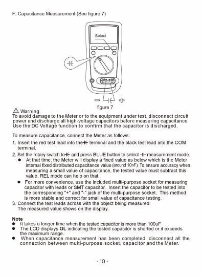
F. Capacitance Measurement (See figure 7)
figure 7
(around 10nF)
n the tested capacitor is more than 100uF

- 11 -
figure 8
When frequency measurement has been completed, disconnect the connectionbetween the testing leads and the circuit under test, and remove the testing leadsaway from the input terminals of the Meter.
G. Frequency Measurement (see figure 8)

- 12 -
H. Transistor hFE Measurement (See figure 9)
figure 9
1. Set the rotary switch to hFE.2. Insert the multi-purpose socket into the input terminal as shown on figure 9.3. Insert the transistor to be tested into the corresponding multi-purpose socket jacks.4. The LCD display hFE nearest value
Note When transistor measurement has been completed, disconnect all the connection
between multi-purpose socket, transistor and the Meter.
I. EF Function (See figure 10)
figure 10
To use EF function, connect the Meter as follows:1. Set the rotary switch to EF and remove the test lead from the input terminals.
2. Place the housing front part with marking towards the object being measured.3. When the test value is too high, the buzzer beeps and the red LED lights.

- 13 -
Operation of Function buttons
To avoid possibility of electric shock, do not use Hold mode to determine if circuitsare without power. The Hold mode will not capture unstable or noisy readings.The Hold mode is applicable to all measurement functions. Press HOLD to enter Hold mode; the Meter beeps. Press HOLD again to exit Hold mode; the Meter beeps. In Hold mode, is displayed.RANGE button
Hold button
Press RANGE to enter the manual ranging mode; the Meter beeps. Press RANGE to step through the ranges available for the selected function; the Meter beeps. Press and hold RANGE for over 2 seconds to return to autoranging; the Meter beeps.MAX MIN button Press MAX MIN to start recording of maximum and minimum values. Steps the display through high (MAX) and low (MIN) readings. The Meter enters manual ranging mode after pressing MAX MIN button. Press and hold MAX MIN for over 2 seconds to exit MAX MIN mode and return to the present measurement range.
Press and hold this button for 2 seconds again to turn off the backlight. 25

- 14 -
Sleep Mode
General Specifications
Maximum Voltage between any Terminals and Grounding: Refer to the different ranges input protection voltage..
Fused Protection for AmA Input Terminal:1A H 240V 6x25mm.
Fused Protection for 10A Input Terminal:10A H 240V 6x25mm. Display
Maximum reading 4000 (frequency 9999), analogue bar graph 41 segments. Measurement Speed: Updates 2~3 times/second. Range: Auto or Manual Polarity Display: Auto Overload indication: Display OL Battery Deficiency: Display
/ 7.1 x 3.4 x 1.8inch384g / 13.6oz

- 15 -
Accurcy Specifications

- 16 -

- 17 -
0.01Hz

- 18 -
This section provides basic maintenance information including battery and fusereplacement instruction.
WarningDo not attempt to repair or service your Meter unless you are qualified to doso and have the relevant calibration, performance test, and service information.To avoid electrical shock or damage to the Meter, do not get water inside the case.
A. General Service Periodically wipe the case with a damp cloth and mild detergent. Do not use abrasives or solvents. To clean the terminals with cotton bar with detergent, as dirt or moisture in the terminals can affect readings. Turn off the power of the Meter when it is not in use. Take out the battery when it is using for a long time.
Maintenance
Do not use or store the Meter in a place of humidity, high temperature, explosive, inflammable and strong magnetic field.
B. Replacing the Battery
figure 11 WarningTo avoid false readings, which could lead to possible electric shock or personalinjury , replace the battery as soon as the battery indicator appears.Make sure the test leads are disconnected from the circuit being tested beforeopening the case bottom.To replace the battery: (See figure 11)1. Turn the Meter power off and remove all connections from the terminals.2. Remove the screw from the tilt stand and the battery compartment and separate the battery compartment and the tilt stand from the case bottom.3. Remove the battery from the battery compartment.4. Replace the battery with a new 9V battery (NEDA1604, 6F22 or 006P)5. Rejoin the tilt stand, battery compartment and case bottom, and reinstall the screw.

- 19 -
Questions or Concerns? [email protected] etekcity.com for more products
C. Replacing the Fuses
figure 12
WarningTo avoid electrical shock or arc blast, or personal injury or damage to the Meter,use specified fuses only in accordance with the following procedure.To test the fuse: (See figure 12)The Meter does not response when measuring current and transistor hFE, go toinspect the Meter built-in fuses.
To replace the Meterís fuse: (See figure 11)1. Turn the Meter power off and remove all the connections from the terminals.2. Remove the screw from the tilt stand and the battery compartment and separate the battery compartment and the tilt stand from the case bottom.3. Remove the two screws from the case bottom, and separate the case top from the case bottom.4. Remove the fuse by gently prying one end loose, then take out the fuse from its bracket.5. Install ONLY replacement fuses with the identical type and specification as follows and make sure the fuse is fixed firmly in the bracket. µA mA range: F1, 1A H 240V, 6x25mm. (CE) 10A range: F2, 10A H 240V, 6x25 mm. (CE)6. Rejoin the case bottom and case top, and reinstall the screw.7. Rejoin the tilt stand, battery compartment and case bottom, and reinstall the screw.
1. Insert the red test lead into the terminal and the black test lead into the COM terminal;
2. Set the rotary switch to resistance measurement.3. Insert the test leads into the 10A and mAuA terminals and measure the
resistance value between these two terminals. If the value is less than 0.5, the fuses are OK, if the display appears OL, the fuses are broken.