User Manual CoolSculpting System
86
ZELTIQ Aesthetics, Inc. 4410 Rosewood Drive Pleasanton, CA 94588 USA www.coolsculpting.com ZELTIQ Customer Service Worldwide: (+1) 925-474-8160 USA: (+1) 888-935-8471 (1-888-ZELTIQ1) User Manual BRZ-101-TUM-EN2-M CoolSculpting System (ZELTIQ Breeze System)
Transcript of User Manual CoolSculpting System

ZELTIQ Aesthetics, Inc. 4410 Rosewood Drive Pleasanton, CA 94588 USA www.coolsculpting.com
ZELTIQ Customer Service Worldwide: (+1) 925-474-8160 USA: (+1) 888-935-8471 (1-888-ZELTIQ1)
User Manual
BRZ-101-TUM-EN2-M
CoolSculpting System (ZELTIQ Breeze System)

2 BRZ-101-TUM-EN2-M
Preface Contents
• Intellectual Property ......................................................................... 2
• Indications for Use ............................................................................ 2
• Contraindications ............................................................................. 3
• Warnings ........................................................................................... 3
• Treatment Sites ................................................................................ 4
• Precautions ....................................................................................... 5
• Adverse Events ................................................................................. 5
• About the System ............................................................................. 6
• Freeze Detect System ....................................................................... 6
• ZELTIQ Clinical Studies ...................................................................... 7
• System Symbols .............................................................................. 18
• User Documentation ...................................................................... 20
Intellectual Property
Copyright© 2019 ZELTIQ Aesthetics, Inc. All rights reserved. Unauthorized duplication or use is prohibited.
COOLSCULPTING®, ZELTIQ®, and FREEZE DETECT® are registered trademarks of ZELTIQ Aesthetics, Inc. The procedures described in this document are covered by U.S. Patent 7,367,341. Additional issued patents and patent applications pending worldwide relate to the products and procedures described in this document. For complete information on patents, go to http://www.coolsculpting.com/about-zeltiq/patents/
Your system may be labeled as the CoolSculpting® System, ZELTIQ® System, ZELTIQ® Breeze System, or the
ZELTIQ® Lipolysis System.
Indications for Use
The CoolSculpting System is a skin cooling or heating device. The device is indicated for cold-assisted lipolysis (breakdown of fat) of the upper arm, bra fat, back fat, banana roll, thigh, abdomen, and flank, or “love handles” in individuals with a Body Mass Index (BMI) of 30 or less. In addition, the device is intended for cold-assisted lipolysis of the submental and submandibular areas in individuals with a BMI up to 46.2. The device is intended to affect the appearance of visible fat bulges in the upper arm, bra fat, back fat, banana roll, submental and submandibular areas, thigh, abdomen and flank. When used for cold-assisted lipolysis of the submental area, the device can also affect the appearance of lax tissue in the submental area.
Cooling with the device may also be used to minimize pain and thermal injury during laser and dermatological treatments and act as a local anesthetic for procedures that induce minor local discomfort.
The CoolSculpting System is also indicated for use to provide localized thermal therapy (hot or cold) to minimize pain post-trauma and post-surgery, and for temporary relief of minor aches, pains, and muscle spasms. The optional massage function can also be used for the temporary relief of minor muscle aches, pain, and spasm and for temporary improvement in local circulation and temporary reduction in the appearance of cellulite.
The ZELTIQ Pretreatment Skin Wipe and Gel/Gelpad facilitate thermal contact of the device with a patient’s skin by mitigating minor variances in device-to-skin contact.
In the United States of America, Federal law restricts this device to sale by or on the order of a physician.

System Overview Contraindications
User Manual 3
Contraindications
Localized skin cooling is contraindicated in patients who have:
• Cryoglobulinemia
• Cold agglutinin disease
• Paroxysmal cold hemoglobinuria
Warnings
Unauthorized modification or repair of the control unit, its components, or supplies may result in unsafe conditions and/or impaired performance. No modification of this equipment is allowed without express authorization from ZELTIQ. Any unauthorized modification or repair will void the warranty.
CoolSculpting System use has not been studied in children, those who are pregnant or lactating, or patients with:
• Known sensitivity to cold such as cold urticaria, Raynaud’s disease, or Chilblains (pernio)
• Known sensitivity or allergy to fructose, glycerin, isopropyl alcohol, or propylene glycol
• Impaired peripheral circulation in the area to be treated
• Neuropathic disorders such as post-herpetic neuralgia or diabetic neuropathy
• Impaired skin sensation
• Open or infected wounds
• Bleeding disorders or concomitant use of blood thinners
• Recent surgery or scar tissue in the area to be treated
• Hernia in or adjacent to the treatment site
• Skin conditions such as eczema, dermatitis, or rashes in the area to be treated
The effect of performing a CoolSculpting treatment (treatment) with a vacuum applicator on a patient who has a hernia in or adjacent to the treatment site has not been studied. The applicator uses vacuum pressure to draw tissue into the applicator cup during the treatment. The vacuum pressure may therefore apply pressure on a pre-existing hernia or pre-existing structurally weak area such as a surgical scar, causing further complications. Physicians should examine that patient for evidence of pre-existing abdominal or femoral hernia prior to use of the device.
The system operates at temperatures below 0°C, which can freeze tissue; clinical events that are common to freezing tissue should be considered.
The use of this device on areas with superficially located nerve branches, arteries, or veins has not been demonstrated to be safe and effective. Such use may result in injury to the patient.
The effect of performing treatments directly over active implanted devices, such as pacemakers and defibrillators, is not known.
Patients with chronic pain, sensitivity to cold, or an anxiety disorder may be more prone to pain or discomfort during the treatment.
Do not use the CoolSculpting System of areas with a subcutaneous fat layer thickness of less than 1cm.
Do not use the CoolSculpting System on areas of decreased sensation or perfusion.
Do not use the CoolSculpting System on areas with minimal underlying muscle mass or on areas with superficially located nerve branches, arteries, or veins.
Do not use the CoolSculpting System on the face, head, genitalia, inguinal creases, axillae, popliteal fossae, antecubital fossae, hands, or feet.

Treatment Sites System Overview
4 BRZ-101-TUM-EN2-M
The use of other electronic medical devices on a patient who is undergoing a treatment might interfere with the correct functioning of the system, possibly resulting in injury to the patient. Do not use other electronic medical devices on a patient who is undergoing a treatment.
Treatment Sites
Observe the following warnings when treating the submental and submandibular areas:
Treatment Site Warning
WARNING: Cold exposure to the hypoglossal nerve may cause tongue deviation following treatment of the submental and submandibular areas.
Hypoglossal Nerve
WARNING: Cold exposure to the marginal mandibular nerve may cause lower lip weakness following treatment of the submental and submandibular areas.
Marginal Mandibular Nerve
WARNING: Cold exposure to the submandibular gland may cause xerostomia, or decrease in saliva production, following treatment of the submental and submandibular areas.
Submandibular Gland
Table 1: Submental and Submandibular Areas Treatment Warnings

System Overview Precautions
User Manual 5
Observe the following warning when treating the upper arm:
Treatment Site Warning
WARNING: Avoid compression of the ulnar nerve during treatment of the upper arm.
Ulnar Nerve
Table 2: Upper Arm Treatment Warning
Precautions
The system is intended for use by a trained physician or a physician-designated medical professional.
If the operator observes a potential safety issue or operational abnormality during use, the treatment should be terminated and ZELTIQ Customer Service should be contacted promptly.
The use of other equipment and supplies with the system has not been tested and may cause unexpected results.
Adverse Events
Common Adverse Events
The following effects can occur in the treatment area during and after a treatment. These effects are temporary and generally resolve within days or weeks.
During a treatment:
• Sensations of pulling, tugging, and mild pinching at the treatment site.
• Intense cold, tingling, stinging, aching, cramping. These sensations subside as the area becomes numb.
Immediately after a treatment:
• Redness and firmness.
• Transient blanching and/or mild bruising around the edges of the treatment area.
• Tingling and stinging.
One to two weeks after a treatment:
• Redness, bruising, and swelling.
• Tenderness, cramping, and aching.
• Itching, skin sensitivity, tingling, and numbness. Numbness can persist up to several weeks after a treatment.
• Sensation of fullness in the back of the throat after submental area treatment.
Rare Adverse Events
• Paradoxical hyperplasia: Visibly enlarged tissue volume within the treatment area, which may develop two to five months after treatment. Surgical intervention may be required.
• Late-onset pain with a typical onset several days after a treatment and resolution within several weeks.

About the System System Overview
6 BRZ-101-TUM-EN2-M
• Frostbite: First- and second-degree frostbite may occur during treatment. It typically resolves without sequelae with proper care.
• Vasovagal symptoms: Dizziness, lightheadedness, nausea, flushing, sweating, or fainting during or immediately after the treatment.
• Subcutaneous induration: Generalized hardness and/or discrete nodules within the treatment area, which may develop after the treatment, and may present with pain and/or discomfort.
• Hyperpigmentation: Hyperpigmentation may occur after treatment. Typically, it resolves spontaneously.
• Hernia: Treatment may cause new hernia formation or exacerbate pre-existing hernia, which may require surgical repair.
• Treatment Area Demarcation (TAD): An aesthetic outcome of treatment in which the patient experiences excessive fat removal in the treatment area, resulting in a visible disruption to the continuous contour of fat, or unwanted indentation in the treated area.
• Cold panniculitis: Cold panniculitis results from injury to adipose tissue exposed to cold and may result in a mild to severe inflammatory response. In mild cases, the symptoms are self-resolving and may include redness, swelling, skin nodules, warmth, tenderness, and possible low-grade fever. These cases typically resolve without long-term sequelae. In more severe cases, an intense inflammatory response may result in more extensive tissue damage, including fat necrosis, which may require medical or surgical intervention.
Frostbite, vasovagal symptoms, sensation in the back of the throat during swallowing, and hyperpigmentation were observed during clinical trials, while the others were reported in post market use.
WARNING: Before using the system, read and understand the User Documentation set (User Documentation on page 19).
About the System
The system is comprised of a control unit, a surface or vacuum applicator, massage function and supplies such as cards, foam borders, gelpads, liners, pretreatment skin wipes, and securement systems. The applicators, foam borders, gel, gelpads, liners, pretreatment skin wipes, and securement systems are patient-applied parts.
During a treatment, the operator applies a gel/gelpad and applicator to the patient’s skin. The vacuum applicator draws tissue into the applicator cup and holds the tissue against the cooling surfaces of the applicator; the surface applicator does not use vacuum pressure. The operator starts the treatment. Sensors in the cooling surfaces of the applicator monitor the skin surface, providing feedback that controls the rate of heat flux. The gel/gelpad protects the skin by providing thermal coupling at the interface between the cooling surfaces of the applicator and the skin. The card provides cycles and profiles for use with the system.
Freeze Detect System
The system operates at temperatures below 0°C, which can freeze tissue. Therefore, the system monitors
tissue during cooling and employs multiple safety features including the Freeze Detect® system, to minimize the risk of damage to tissue. In spite of these measures, on rare occasions, the Freeze Detect system can detect a possible freeze condition.
The Freeze Detect system is comprised of several features, including thermal sensors and proprietary algorithmic software. Freeze Detect is an integral part of the CoolSculpting System and is automatically employed when a treatment is initiated. When the Freeze Detect system detects a possible freeze condition, it stops the treatment and displays a Z409 message. If you receive this message, remove the applicator and gelpad or gel, and assess the tissue before taking further action and do not retreat for at least 24 hours, for CoolAdvantage and CoolMini applicators. For all other applicators, if you receive a second Z409 message for one treatment site, discontinue the treatment for the site, and do not retreat for at least 24 hours. Failure to follow instructions could result in injury to the patient, including first- or second-degree burns. Second-degree burns or complications of second-degree burns may result in hypopigmentation.

System Overview ZELTIQ Clinical Studies
User Manual 7
ZELTIQ Clinical Studies
NOTE: When the flank, abdomen, and thigh studies were performed, the degree of cooling or warming during a treatment was expressed as the Cooling Intensity Factor (CIF). The CIF was an index that represented the rate of heat flux into or out of tissue relative to 37°C. A positive CIF described the rate of heat flux out of tissue. A negative CIF referred to the rate of heat flux into tissue. The studies in this section used the CIF as a unit of measure. Current treatment parameters refer to the temperature at the surface of the applicator.
The ZELTIQ CoolSculpting System has undergone pre-clinical and clinical investigation (data on file at ZELTIQ). The clinical investigation and results pertaining to skin cooling for fat layer reduction in submental and submandibular areas, abdomen, flanks, thighs, and alternate treatment parameters are summarized in this section.
The below table summarizes the efficacy information for each study that has been conducted. Further details on each study can be found in the individual summaries below.
Treatment Site Photographic Review Results (% correct)
Ultrasound Results (mean reduction in mm)
Subject Satisfaction (% satisfied)
Flanks 88.6 N/A 82.1
Abdomen 85.3 1.9 62
Inner thigh 90.5 2.8 93.3
Outer thigh 83.9 2.5 86.5
Modified treatment parameters 85 3.92 88.37
Submental Area 91.4 2.0 83.3
Upper Arm 85.2 [72.9%, 93.4%] 3.2 63.3
Flank Study
Assessment Time Line
A clinical study that enrolled 60 healthy adult subjects, aged 23 to 65 years at two clinical centers was conducted from August 2007 through June 2008. Each individual received one or more applications of the ZELTIQ CoolSculpting System with a ZELTIQ vacuum applicator. Assessments of treatment efficacy and safety were performed as follows:
Day 0 Treatment 1 Week 2 Months 6 Months
C
on
sen
t Sc
reen
ing
P
ho
togr
aph
s
U
ltra
sou
nd
B
asel
ine
Dem
ogr
aph
ics
C
linic
al A
sse
ssm
ent
P
ho
ne
Follo
w-u
p
C
linic
al A
sse
ssm
ent
P
ho
togr
aph
s
U
ltra
sou
nd
C
linic
al A
sse
ssm
ent
P
ho
togr
aph
s
U
ltra
sou
nd
C
linic
al A
sse
ssm
ent
Four groups were treated with the treatment regimens shown in Table 3. A short period (two to five minutes) of simultaneous tissue cooling and massage was used during each treatment to facilitate lipolysis. For each subject, the larger of the two flank bulges was treated, leaving the contralateral side as an untreated control.

ZELTIQ Clinical Studies System Overview
8 BRZ-101-TUM-EN2-M
Treatment Group
Number of Subjects
Cooling Intensity Factor
(CIF)
Temperature Cooling Duration (minutes)
Energy Extraction Rate (mW/cm2)
1 28 33 -4ºC 60 min 63.6
2 11 37 -7ºC 30 min 68.3
3 11 37 -7ºC 45 min 68.3
4 10 42 -10°C 30 min 72.9
Table 3: Treatment Regimens
Clinical Efficacy Results
Blinded Photographic Evaluation
Efficacy was determined by photographic evaluation, ultrasound fat-thickness measurements, clinical assessments, and subject satisfaction. A blinded photographic evaluation was performed of 50 evaluable subjects in which three blinded reviewers were provided two series of photographs for each subject, one series taken at baseline, and the other taken post-treatment. Each reviewer was asked to identify the baseline photo series independently. In the blinded photographic review of all subjects the reviewers correctly identified the baseline photo series 88.6% of the time.
Treatment Group
Number of Subjects All Data % Correct ± % SE
All Data p-values
All Groups 50 88.6 ± 4.1 < 0.001*
Group 1 20 90.7 ± 5.1 < 0.001*
Group 2 10 90.0 ± 9.5 < 0.005*
Group 3 11 90.9 ± 8.7 < 0.001*
Group 4 9 66.7 ± 15.7 < 0.4
Table 4: Independent Photo Review Results
Post-treatment ultrasound measurements of fat layer thickness were compared with baseline measurements, using the untreated control side to normalize for weight changes that may have occurred during the follow-up period. The fat layer reduction as measured with ultrasound averaged 18.7% from baseline, after being normalized by the untreated control side. Ultrasound measurements at two months and at six months indicate that on average, 75% of the total fat layer reduction for a subject was realized within two months of treatment. Overall, 82.1% of subjects enrolled in the study indicated they were satisfied with the treatment.
Clinical Safety Results
Reported side effects included pain during or post-treatment, minor or significant bruising of the treated area, temporary hypoesthesia, tingling, erythema, and edema. All side effects during this study resolved spontaneously, most resolved within hours or days of the treatment.
Resolution of Hypoesthesia
Partial numbness and, to a lesser extent tingling, over the skin of the application site were reported for all subjects immediately post-treatment and for 68% of subjects by one week post-treatment. Partial numbness or tingling is a temporary and anticipated effect of the treatment and was found to resolve without intervention within two to three weeks on average, although in 8.3% of the cases these effects endured for as long as two months.

System Overview ZELTIQ Clinical Studies
User Manual 9
Adverse Events
There were four relatively minor adverse events; each was anticipated and resolved without intervention. During treatment, two adverse events were reported involving pain and/or discomfort. Each of these resolved after treatment was discontinued. Following treatment, two adverse events were reported: severe bruising and minor cramping or muscle spasm in the treatment area. Both resolved without intervention within four weeks. None of the adverse events reported during this study was considered serious or unanticipated.
During the clinical investigation, serum lipids and liver enzymes were measured in a subset of 20 subjects at times from 1 week to 12 weeks post-treatment to determine whether the CoolSculpting treatment had an effect on clinical chemistry. The following analytes were measured: Cholesterol, Triglycerides, HDL Cholesterol, LDL Cholesterol, VLDL Cholesterol, Cholesterol/HDL Ratio, Total Protein, Albumin, AST-SGOT, ALT-SGPT, Total Bilirubin, and Direct Bilirubin. No statistically significant changes were found for serum lipids or liver enzyme data from baseline over the duration of the study.
BMI Recommendations
For best results, patients should have a BMI of 30 or less and should maintain a healthy lifestyle following a treatment. The study evaluations for this clinical investigation included subjects with a Body Mass Index up to 38.7; however, patients who are significantly overweight are less likely to appreciate a significant improvement with a single treatment.
Skin Type
The clinical investigation subject population included Fitzpatrick skin types ranging from I to VI, with the majority of subjects being types II to IV. No change in skin pigmentation was observed following a treatment.
Based on the clinical data, ZELTIQ recommends that practitioners read this Preface carefully and pay special attention to warnings and cautions throughout the User Manual and Directions for Use.
Abdominal Study
A separate clinical investigation with the CoolSculpting device on the fat layer of the abdomen resulted in a clinically measurable reduction of local subcutaneous fat of the abdomen, in the same manner that that was previously demonstrated for the flank. Treatments were performed at -10°C (CIF 42) for 60 minutes. The primary endpoint results (Independent Photo Review) revealed that the percent correct identification of the pre-treatment images exceeded the pre-established 80% criterion and is statistically significant. Fat layer reduction in the treated area of the abdomen was further documented by ultrasound imaging which also revealed a statistically significant and clinically relevant reduction. Overall, 62% of subjects enrolled in the study indicated they were satisfied with the treatment.
Study data also revealed that the treatment is as safe when used in the abdomen as previously tested for the flank. Data collected during the study demonstrated that the post-treatment lipid profile and liver function tests showed no statistically significant difference from baseline. This was true for mean values for the entire population as well as for each individual subject. No serious adverse events were reported during the abdomen study. The results of this clinical study provide supportive evidence that treatment with the CoolSculpting device provides consistent and clinically significant reduction of the fat layer of the abdomen.
Summary of Thigh Studies
ZELTIQ conducted two clinical investigations to determine the safety and efficacy of cold-assisted lipolysis in the thigh region. In the inner thigh study, 90 treatments were completed with the flat cup vacuum applicator at -10°C (CIF 42); in the outer thigh study, 40 treatments were completed with the belt applicator at -10°C (CIF 23). Follow-up data is available for both studies up to 16 weeks post-treatment. Three blinded evaluators assessed the photos for visible reduction of fat in the treatment areas at the 16 -week follow-up visit. The evaluators were presented with the series of photographs and were asked to identify the pre-treatment photographs for each subject.

ZELTIQ Clinical Studies System Overview
10 BRZ-101-TUM-EN2-M
The overall correct identification rate by the three evaluators was 90.5% for the inner thigh study and 83.9% for the outer thigh study. At least two out of three evaluators correctly identified 90.5% of all photo pairs for the inner thigh study and 87.1% for the outer thigh study. The results demonstrate that the ZELTIQ CoolSculpting System affects the appearance of the thighs.
Change in subcutaneous fat layer thickness was also measured by ultrasound at 16-weeks: In the inner thigh study average fat thickness change was a 2.7 mm decrease. In the outer thigh study average fat thickness change was a 2.6 mm decrease. Overall for the inner thigh study, 93.3% of subjects enrolled in the study indicated they were satisfied with the treatment. Overall for the outer thigh study, 86.5% of subjects enrolled in the study indicated they were satisfied with the treatment.
Adverse events reported during the studies included numbness and mild contour irregularity. All adverse events but one resolved by the 16 week follow-up. A mild case of hyperpigmentation in the treatment area persisted beyond the 16 week follow-up. This is an adverse event that typically resolves spontaneously. The clinical investigations demonstrate that use of the ZELTIQ CoolSculpting System can safely and effectively induce cold-assisted lipolysis in the thigh in the same manner as in the abdomen and flanks.
Summary of Study with Modified Treatment Parameters
A study of a modified treatment parameter was designed to evaluate the safety and efficacy of the CoolSculpting System with a colder, shorter treatment. In this study, 63 treatments were completed with the CoolCurve+ applicator on 45 subjects. Each subject received one or two non-overlapping unilateral vacuum treatments of the flank at a treatment temperature of -15°C for 45 minutes; immediately after each treatment, the treated tissue was massaged manually for two minutes. Follow-up data is available for up to 16 weeks post-treatment.
Subject safety was assessed throughout the study, including immediately post-treatment, one-week post-treatment telephone follow-up, and at 8- and 16-week post-treatment clinic visits. The primary safety endpoint was the occurrence of device- or procedure-related adverse events. No serious adverse events were reported during the study or 16-week follow-up period. Adverse events reported during the study included mild numbness, post-treatment pain, hyperpigmentation, subcutaneous induration, and first-degree burn in the treatment area. All but three adverse events resolved by the 16 week follow-up. Three subjects reported mild numbness at the 16-week follow-up; all three reported resolution within the next 19 calendar days.
The primary efficacy endpoint was the change in fat layer thickness as measured with ultrasound. Fat layer reduction in the treated area of the flank was documented by ultrasound imaging pre-treatment and at 8 and 16 weeks post-treatment. Subsequent evaluation of the ultrasound images revealed a statistically significant and clinically relevant reduction.
Secondary efficacy endpoints included correct identification of pre- and post-treatment images by three blinded independent reviewers, and subject satisfaction assessment by subject questionnaire. Photos taken at baseline and at the 16-week follow-up visits were reviewed by a blinded independent panel of three physicians board-certified in dermatology or plastic surgery. The overall correct identification rate by the three evaluators was 85%, which exceeded the pre-established 80% criterion and is statistically significant.
The secondary efficacy endpoint for subject satisfaction was performed by means of a questionnaire with questions about the comfort and subjective results of the treatment, and about the subject’s attitudes toward CoolSculpting after treatment. With the exception of comfort, the majority of responses were positive to very positive. Overall, 88.37% of subjects enrolled in the study indicated they were satisfied with the treatment.
These clinical findings demonstrate that use of the CoolSculpting System can safely and effectively induce cold-assisted lipolysis with colder temperatures down to -15°C for shorter duration treatments with vacuum and surface applicators.
Submental Area Study
ZELTIQ conducted a clinical investigation to determine the safety and efficacy of the CoolSculpting System for affecting the appearance of visibly localized subcutaneous fat localized in the submental area.

System Overview ZELTIQ Clinical Studies
User Manual 11
In this study, 60 subjects were enrolled at three clinical sites. Sixty initial treatments were performed with the prototype CoolMini vacuum applicator; 59 subjects were re-treated at the 6-week follow-up visit. Treatments were performed at -10°C for 60 minutes. Follow-up data is available through 12 weeks post-treatment. Subject safety was assessed throughout the study.
The primary safety endpoint was the measurement of all device- or procedure-related adverse events. All adverse events reported during and after the treatment were included in the safety analysis. The primary safety endpoint was met. No device- or procedure-related serious adverse events (SAE) and no unanticipated adverse device effects (UADE) occurred during the study. Four device- or procedure-related adverse events were reported and have resolved. Clinical safety assessment showed anticipated side-effects, all of which resolved over the course of the study. The safety data recorded during this study supports the safety of the treatment parameters and device investigated.
The primary efficacy endpoint was correct identification of pre-treatment vs. 12-week post-final treatment images by 3 blinded independent reviewers. The overall correct identification rate by the 3 reviewers was 91% for the per-protocol population (n=58), which met the pre-established 80% criterion for success. The primary efficacy endpoint was met.
Reduction in subcutaneous fat layer thickness as measured by ultrasound at 12-weeks post-final treatment was a secondary efficacy endpoint for this study. Analysis of the per-protocol data (57 subjects) showed a statistically significant (p<0.0001) reduction of 0.20 cm. Therefore, the secondary efficacy endpoint for reduction of fat layer thickness was met.
The secondary efficacy endpoint for subject satisfaction was assessed by a questionnaire administered at 12 weeks post-final treatment. Overall, 83.3% of subjects enrolled in the study indicated they were satisfied with the treatment and 80% reported that they would recommend the treatment to a friend.
These clinical findings demonstrate that use of the CoolSculpting System can safely and effectively affect the appearance of visible fat bulges in the submental area with treatment at -10°C for 60 minutes.
Summary of Upper Arm Study
ZELTIQ conducted a clinical investigation to evaluate the safety and efficacy of cryolipolysis for non-invasive reduction of upper-arm fat.
In this study, 30 subjects were enrolled at two clinical sites. Sixty initial treatments were performed with a prototype of the CoolAdvantage applicator (CoolFit with aluminum Insert). Each subject was treated once on each upper arm, at -11°C for 35 minutes. Follow-up data is available through 12 weeks post-treatment. Subject safety was assessed throughout the study.
The primary safety endpoint was the incidence of unanticipated adverse device effects. Clinical safety assessment showed anticipated side-effects. There were 4 patients with prolonged numbness lasting greater than 12 weeks. No unanticipated adverse device effects, or serious device- or procedure-related adverse effects occurred. All device- and/or procedure-related adverse events resolved spontaneously. The primary safety endpoint was met.
The primary efficacy endpoint involved independent panel review of pre- and 12-week post-treatment photographs of the treatment area for discernible fat layer reduction. The per protocol population consisted of all the treated subjects followed for 12 weeks with weight change of no more than 5% of total body weight at the time the 12 week images were taken. For the per protocol population, the correct baseline photograph identification rate by the independent panel reviewers was 85.2% [72.9%, 93.4%].
Further evidence of treatment efficacy is found in the data from ultrasound measurements of fat reduction at the treated areas, with significant reduction in the fat layer (0.32 cm) from baseline to 12 weeks post-treatment.
The secondary efficacy endpoint for subject satisfaction was assessed by an IRB-approved questionnaire administered at 12 weeks post-treatment. 72.41% of the subjects found the procedure to be comfortable to very comfortable, and 63.3% of the subjects reported that they would recommend the procedure to a friend.

ZELTIQ Clinical Studies System Overview
12 BRZ-101-TUM-EN2-M
These clinical findings demonstrate that use of the CoolSculpting System can safely and effectively affect the appearance of visible fat bulges in the upper arm area with treatment at -11°C for 35 minutes.
Summary of Submental Area Study
A prior study (ZA14-002), approved by the Food and Drug Administration (FDA) under IDE G140083, reported the efficacy of cryolipolysis for non-invasive reduction of submental fat. Subsequently, a retrospective study was carried out in which standardized, masked, photographic images from the original ZELTIQ-sponsored clinical study were evaluated quantitatively to determine the efficacy of the CoolSculpting treatment in affecting the appearance of lax tissue in the submental area.
This retrospective study started with the ZA14-002 per-protocol population (n=58) for analysis, excluded one subject due to excessive hair in the submental region, and used the remaining fifty-seven (57) subjects for analysis. Lateral photographic views of the face taken at baseline and at the 12-week post-final treatment visit were included in the analysis. Each photograph was cropped and masked prior to evaluation. A board-certified plastic surgeon identified the following anatomical points on each photograph: the lateral canthus, the anterior-most point where the nostril meets the columella, and the point where the chin meets the neck (submental crease). AutoCAD software was used to apply lines to each photograph, and areas in the submental region were measured. A responder analysis was performed with the criteria being ≥ 20 mm2 decrease in area as measured on both the right lateral and left lateral views of the region.
A second analysis was performed in which reviewers compared the results from the responder analysis against results from the independent physician review panel of photos, which had been conducted in the previous study. This second analysis indicated that 77.2% (44/57) of subjects exhibited a ≥ 20 mm2 area reduction in the submental and neck tissue. Of those 44 subjects, 42 (95.5%) were correctly identified by the physician panel as having a visible response.
System Overview ZELTIQ Clinical Studies
User Manual 13
Summary of Clinical Study Publications
A review of clinical publications revealed 4,792 cryolipolysis treatments during clinical studies. From these studies, we compiled the numbers of treatments in several anatomical areas: 1,695 treatments in the abdomen, 1,987 treatments in the flanks, 501 treatments in the back, 323 treatments in the inner thigh, 150 treatments in the lateral thigh, 3 treatments in the anterior thigh, 119 treatments in the submental area, and 14 treatments in the banana roll region.
Efficacy was measured by several techniques including ultrasound and caliper measurements, circumferential measurements, 3D quantification of volume reduction, and blinded, independent review of clinical photographs. Based on the compilation of data from these studies, the overall mean ultrasound fat layer reduction ranged from 10.3 to 25.5% and 1.9 to 8.3 mm.
Compiled mean caliper fat layer reduction ranged from 14.7 to 23.0%. Single studies showed mean 0.9 cm circumferential reduction in the inner thigh, 2.4 cm circumferential reduction in the flanks, 6.8 cm circumferential reduction in the abdomen, and 39.6 cm3 volumetric reduction in the flanks.
Based on the compilation of these various studies, the overall mean ultrasound fat layer thickness reduction was 20.6% and 3.9 mm. Compiled mean caliper fat layer reduction was 22.3%. The independent photo review was 89.7% correct, on average.
As shown by multiple clinical studies submitted for clearance to the agency, the summary of published data shows a similarly high safety and efficacy profile for the cryolipolysis procedure. Common procedural side effects include erythema, bruising, and numbness, which typically resolve within one month of treatment. Based on the literature review, 6 cases would be considered serious adverse events. These serious adverse events include three cases of paradoxical hyperplasia in the abdomen, one case of paradoxical hyperplasia in the abdomen, back, and flanks, one case of contour irregularity in the abdomen, and one case of contour irregularity in the flank. For 4,792 treatments in published studies, the incidence of serious adverse events is very low (0.13%). Given the fact that 76.8% of treatments were to the abdomen and flanks, this incidence rate shows no clear indication of treatment site specificity. The clinical publications indicate that cryolipolysis is a safe and effective non-surgical procedure for subcutaneous fat reduction.
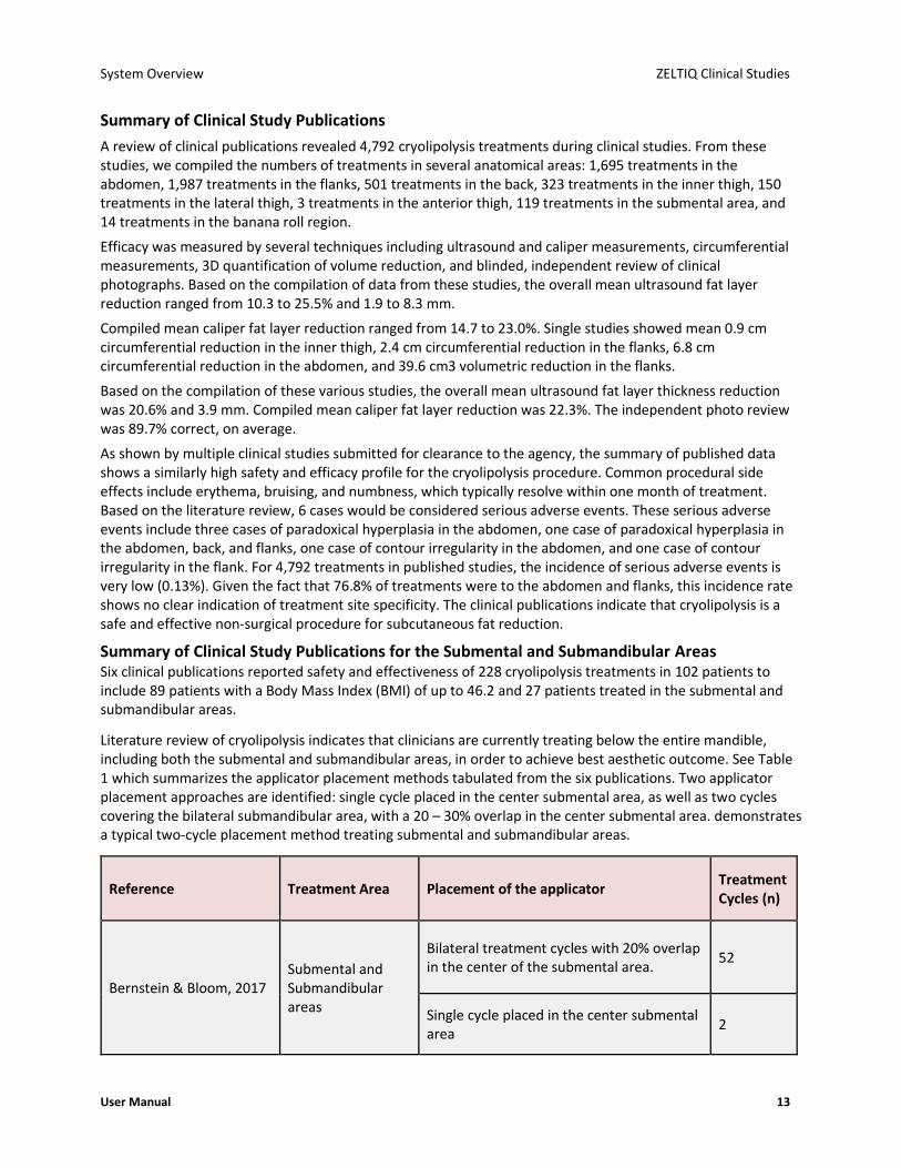
Summary of Clinical Study Publications for the Submental and Submandibular Areas Six clinical publications reported safety and effectiveness of 228 cryolipolysis treatments in 102 patients to include 89 patients with a Body Mass Index (BMI) of up to 46.2 and 27 patients treated in the submental and submandibular areas.
Literature review of cryolipolysis indicates that clinicians are currently treating below the entire mandible, including both the submental and submandibular areas, in order to achieve best aesthetic outcome. See Table 1 which summarizes the applicator placement methods tabulated from the six publications. Two applicator placement approaches are identified: single cycle placed in the center submental area, as well as two cycles covering the bilateral submandibular area, with a 20 – 30% overlap in the center submental area. demonstrates a typical two-cycle placement method treating submental and submandibular areas.
Reference Treatment Area Placement of the applicator Treatment Cycles (n)
Bernstein & Bloom, 2017 Submental and Submandibular areas
Bilateral treatment cycles with 20% overlap in the center of the submental area.
52
Single cycle placed in the center submental area
2

ZELTIQ Clinical Studies System Overview
14 BRZ-101-TUM-EN2-M
Reference Treatment Area Placement of the applicator Treatment Cycles (n)
Kilmer, Burns, & Zelickson, 2016
Submental area Single cycle placed in the center submental area
119
Leal Silva, Hernandez, Vazquez, Leal Delgado, & Blanco, 2017
Submental area Single cycle placed in the center submental area
30
Lee, Ibrahim, Arndt, & Dover, 2018
Submental and Submandibular areas
Bilateral treatment cycles with 30% overlap in the center of the submental area. Applicator is placed 1 to 2 cm from inferior aspect of mandible, in sequence.
2
Li, DaSilva, Canfield, & McDaniel, 2018
Submental and Submandibular areas
Single cycle placed in the center submental area
1
Bilateral treatment cycles with overlap in the center of the submental area.
2
Suh et al., 2018 Submental and Submandibular areas
Bilateral treatment cycles with 30% overlap in the center of the submental area.
20
Reported safety included common procedural side effects such as erythema, bruising, numbness, edema,
blanching, tingling, increased sensitivity, itching, pigmentation changes, tenderness, and hoarseness, typically
resolving within one month of treatment. It is believed that these side effects are not specifically quantified
and reported in all publications because they are expected, self-resolving, and considered minor; thus, reports
of erythema, bruising, pain, and transient numbness are likely under-reported. From the publications that
reported a total of 228 treatment cycles, the most common side effects at 1-Week post-treatment were
numbness (105 reports), tingling (24), edema (9), and erythema (3 reports).
Several techniques measured effectiveness, techniques including ultrasound measurement, caliper
measurement, Magnetic Resonance Imaging (MRI), three-dimensional (3D) quantification of volume reduction,
patient satisfaction, and blinded, independent review of clinical photographs. The mean ultrasound
measurement of fat layer reduction was 2.4 mm with a range from 2.0 to 2.8 mm. The mean caliper
measurement of fat layer reduction was 3.17 mm (around 33%) with a range from 2.3 to 4.0 mm. The single
study using MRI imaging showed mean reduction of 1.78 mm or 17% subcutaneous fat layer reduction. The
3D imaging showed a mean calculated reduction of 8.5 mL fat volume, and calculated reduction in submental
laxity by 2.25 mm. Three-dimensional volumetric measurement showed a fat reduction of 4.82 cm3.
Blinded, independent photo review was conducted in several studies with correct identification of baseline
photographs ranging from 60% to 91%, averaging 77%. Patient satisfaction ranged from 80% to 93%,
averaging 85%.
There were no device or procedure-related serious adverse events related to treatment of the submental and
submandibular areas in the six publications.

System Overview ZELTIQ Clinical Studies
User Manual 15
References
Published Papers
1. Bernstein EF, Bloom JD. Safety and Efficacy of Bilateral Submental Cryolipolysis With Quantified 3-Dimensional Imaging of Fat Reduction and Skin Tightening. JAMA Facial Plast Surg. 2017; 19(5), 350-357.
2. Leal Silva H, Hernandez EC, Vazquez MG, Leal Delgado S, Blanco AP. Noninvasive submental fat reduction using colder cryolipolysis. J Cosmet Dermatol. 2017; 1-6.
3. Lee NY, Ibrahim O, Arndt KA, Dover JS. Marginal Mandibular Injury After Treatment With Cryolipolysis. Dermatol Surg. 2018; 1-3.
4. Li MK, DaSilva D, Canfield D, McDaniel DH. Use of 3-Dimensional Imaging in Submental Fat Reduction After Cryolipolysis. Dermatol Surg. 2018; 889-892.
5. Suh DH, Park JH, Jung HK, Lee SJ, Kim JH, Ryu JH. Cryolipolysis for submental fat reduction in Asians. Journal of Cosmetic and Laser Therapy. 2018; 24-27.
6. Kilmer SL, Burns AJ, Zelickson BD. Safety and efficacy of cryolipolysis for non-invasive reduction of submental fat. Lasers Surg Med. 2015 Nov 26.
7. Seaman SA, Tannan SC, Cao Y, Peirce SM, Gampper TJ. Paradoxical Adipose Hyperplasia and Cellular Effects after Cryolipolysis: A Case Report. Aesthet Surg J. 2016 Jan; 36(1):NP6-NP13.
8. Keaney TC, Gudas AT, Alster TS. Delayed Onset Pain Associated With Cryolipolysis Treatment: A Retrospective Study With Treatment Recommendations. Dermatol Surg. 2015 Nov; 41(11):1296-9.
9. Stefani WA. Adipose Hypertrophy Following Cryolipolysis. Aesthet Surg J. 2015 Sep; 35(7):NP218-20.
10. Mahmoud ELdesoky MT, Mohamed Abutaleb EE, Mohamed Mousa GS. Ultrasound cavitation versus cryolipolysis for non-invasive body contouring. Australas J Dermatol. 2015 Aug 24.
11. Wanitphakdeedecha R, Sathaworawong A, Manuskiatti W. The efficacy of cryolipolysis treatment on arms and inner thighs. Lasers Med Sci. 2015 Nov; 30(8):2165-9.
12. Garibyan L, Cornelissen L, Sipprell W, Pruessner J, Elmariah S, Luo T, Lerner EA, Jung Y, Evans C, Zurakowski D, Berde CB, Anderson RR. Transient Alterations of Cutaneous Sensory Nerve Function by Noninvasive Cryolipolysis. J Invest Dermatol. 2015 Nov; 135(11):2623-31.
13. Singh SM, Geddes ER, Boutrous SG, Galiano RD, Friedman PM. Paradoxical adipose hyperplasia secondary to cryolipolysis: An underreported entity? Lasers Surg Med. 2015 Aug; 47(6):476-8.
14. Zelickson BD, Burns AJ, Kilmer SL. Cryolipolysis for safe and effective inner thigh fat reduction. Lasers Surg Med. 2015 Feb; 47(2):120-7.
15. Stevens WG, Bachelor EP. Cryolipolysis conformable surface applicator for non-surgical fat reduction in lateral thighs. Aesthet Surg J. 2015 Jan; 35(1):66-71.
16. Carruthers J, Stevens WG, Carruthers A, Humphrey S. Cryolipolysis and skin tightening. Derm Surg. 2014 Dec; 40 Suppl 12:S184-9.
17. Bernstein EF, Bloom JD, Basilavecchio LD, Plugis JM. Non-invasive fat reduction of the flanks using a new cryolipolysis applicator and overlapping, two-cycle treatments. Lasers Surg Med. 2014 Dec; 46(10):731-5.
18. Boey GE, Wasilenchuk JL. Fat Reduction in the Inner Thigh Using a Prototype Cryolipolysis Applicator. Dermatol Surg. 2014; 40(9):1004-9.
19. Stevens WG. Does Cryolipolysis Lead to Skin Tightening? A First Report of Cryodermadstringo. Aesthet Surg J. 2014; 34(6): NP32-NP34.

ZELTIQ Clinical Studies System Overview
16 BRZ-101-TUM-EN2-M
20. Sasaki GH, Abelev N, Tevez-Ortiz A. Noninvasive Selective Cryolipolysis and Reperfusion Recovery for Localized Natural Fat Reduction and Contouring. Aesthet Surg J. 2014 Mar; 34(3):420-31.
21. Garibyan L, Sipprell WH 3rd, Jalian HR, Sakamoto FH, Avram M, Anderson RR. Three-Dimensional Volumetric Quantification of Fat Loss Following Cryolipolysis. Lasers Surg Med. 2014 Feb; 46(2):75-80.
22. Jalian HR, Avram MM, Garibyan L, Mihm MC, Anderson RR. Paradoxical Adipose Hyperplasia after Cryolipolysis. JAMA Dermatol. 2014 Mar; 150(3):317-9.
23. Boey GE, Wasilenchuk JL. Enhanced Clinical Outcome with Manual Massage Following Cryolipolysis Treatment: A 4-Month Study of Safety and Efficacy. Lasers Surg Med. 2014 Jan; 46(1):20-6.
24. Stevens WG, Pietrzak LK, Spring MA. Broad Overview of a Clinical and Commercial Experience with CoolSculpting. Aesthet Surg J. 2013 Aug 1; 33(6):835-46.
25. Dierickx CC, Mazer JM, Sand M, Koenig S, Arigon V. Safety, Tolerance, and Patient Satisfaction With Noninvasive Cryolipolysis. Dermatol Surg. 2013 Aug; 39(8):1209-16.
26. Bernstein EF. Longitudinal Evaluation of Cryolipolysis Efficacy: Two Case Studies. J Cosmet Dermatol. 2013 Jun; 12(2):149-52.
27. Kotlus BS, Mok C. Evaluation of Cryolipolysis for Subcutaneous Fat Reduction. Am J of Cosmet Surg. 2013; 30(2), 89-93.
28. Lee, J. Clinical Efficacy of Fat Reduction on the Thigh of Korean Women through Cryolipolysis. Obes Weight Loss Ther 2013, 3:6.
29. Shek SY, Chan NPY, Chan HL. Non-Invasive Cryolipolysis for Body Contouring in Chinese — a First Commercial Experience. Lasers Surg Med. 2012 Feb; 44(2):125-30.
30. Brightman L, Geronemus R. Can Second Treatment Enhance Clinical Results in Cryolipolysis? Cosmet Dermatol. 2011; 24(2):85-88.
31. Klein K, Zelickson B, Riopelle JG, Okamoto E, Bachelor EP, Harry RS, Preciado JA. Non-Invasive Cryolipolysis for Subcutaneous Fat Reduction Does Not Affect Serum Lipid Levels or Liver Function Tests. Lasers Surg Med. 2009 Dec; 41(10):785-90.
32. Coleman SR, Sachdeva K, Egbert BM, Preciado J, Allison J. Clinical Efficacy of Noninvasive Cryolipolysis and Its Effects on Peripheral Nerves. Aesthetic Plast Surg. 2009 Jul; 33(4):482-8.
Published Abstracts
1. Loss L. Cryolipolysis Treatment of a Lipoma: A Case Study. Lasers Surg Med. 2014; 45(4):364.
2. Burns AJ, Saltz R, Stevens G, Kilmer S. Cryolipolysis Using the Treatment to Transformation Approach: One Year Follow Up. Lasers Surg Med. 2014; 46(S25):18.
3. Jalian HR, Tam J, Garibyan L, Anderson RR. Selective Cryolysis of Sebaceous Glands. Lasers Surg Med. 2014; 46(S25):2.
4. Macedo O, Corradini C, Matayoshi L. Cryolipolysis Treatment for Subcutaneous Fat Layer Reduction. Journal of the American Academy of Dermatology. 2012; 66(4):Suppl. 1: AB25.
5. Mayoral F, Kaminer M, Kilmer S, Weiss R, Zelickson B. Effect of Multiple Cryolipolysis Treatments on the Abdomen. Lasers Surg Med. 2012; 44(S24):15.
6. Dover J, Kaminer M, Teahan M, Barrett L. Patient Satisfaction at 2 and 6 Months after a Single Non-Invasive Cryolipolysis Treatment for Subcutaneous Fat Layer Reduction. Lasers Surg Med. 2011; 43(S23):968.
7. Kim H, Suh D, Park J, Rhue J, Lee S, Song K, Shin M, Ok C. Clinical Evaluation of a Non-Invasive Cryolipolysis for the Treatment of Subcutaneous Fat Removal in Korean Patients. Lasers Surg Med. 2011; 43(S23):973.

System Overview System Symbols
User Manual 17
8. Burns JA, Allison J, Bachelor E, Dover J, Coleman S, Fitzpatrick R, Garden J, Geronemus R, Goldberg D, Kilmer S, Kramer S, Levinson M, Mayoral F, Okamoto E, Tanzi E, Riopelle J, Weiss R, Zelickson B. Analysis of Side Effects of Non-Invasive Cryolipolysis for Subcutaneous Fat Layer Reduction – Interim Report from Controlled Clinical Trials. Lasers Surg Med. 2010; 42(S22):21.
9. Dover J, Burns J, Coleman S, Fitzpatrick R, Garden J, Goldberg D, Geronemus R, Kilmer S, Mayoral F, Tanzi E, Weiss R, Zelickson B. A Prospective Clinical Study of Noninvasive Cryolipolysis for Subcutaneous Fat Layer Reduction – Interim Report of Available Subject Data. Lasers Surg Med. 2009; 41(S21):43.
10. Kaminer M, Weiss R, Newman J, Allison J. Visible Cosmetic Improvement with Cryolipolysis: Photographic Evidence. Presented at the Annual Meeting of the American Society for Dermatologic Surgery, 2009, Phoenix, AZ.
ZELTIQ Customer Service
• Worldwide: (+1) 925-474-8160
• U.S.A.: 1-888-935-8471 (1-888-ZELTIQ1)
System Symbols
The following symbols are used on the components of the system and on its supplies and packaging.
Manufacturer Indicates the medical device manufacturer, as defined in EU Directives 90/385/EEC, 93/42/EEC and 98/79/EC. Per ISO 15223-1 Reg. No. 3082
Authorized Representative in the European Community Indicates the Authorized representative in the European Community. Per ISO 15223-1
Refer to instruction manual/booklet To signify that the instruction manual/booklet must be read. Per IEC 60878 Reg. No. M002
Consult instructions for use (user manual, directions for use) Indicates the need for the user to consult the instructions for use. Per ISO 15223-1 Reg. No. 1641
Conformité Européene or European Conformity Indicates manufacturer declaration that the product complies with the essential requirements of the relevant European health, safety and environmental protection legislation. Article 17
Caution Indicates the need for the user to consult the instructions for use for important cautionary information such as warnings and precautions that cannot, for a variety of reasons, be presented on the medical device itself. Per ISO 15223-1 Reg. No. 0434A
Do not reuse Indicates a medical device that is intended for one-time use only. Per ISO 15223-1 Reg. No. 1051
Do not use if package is damaged Indicates a medical device that should not be used if the package has been damaged or opened. Per ISO 15223-1 Reg. No. 2606
Type BF applied part To identify a type BF applied part complying with IEC 60601-1. Per IEC 60417 Reg. No. 5333
Potential for Electromagnetic Interference Per IEC 60417 Reg. No. W005

System Symbols System Overview
18 BRZ-101-TUM-EN2-M
Catalog number Indicates the manufacturer’s catalog number so that the medical device can be identified. Per ISO 15223-1 Reg. No. 2493
Serial number Indicates the manufacturer’s serial number so that a specific medical device can be identified. Per ISO 15223-1 Reg. No. 2498
Quantity
Batch code Indicates the manufacturer’s batch code so that the batch or lot can be identified. Per ISO 15223-1 Reg. No. 2492
Protective earth ground To identify any terminal which is intended for connection to an external conductor for protection against electric shock in case of a fault, or the terminal of a protective earth (ground) electrode. Per IEC 60417 Reg. No. 5019
cTUVus: Meets minimum electrical safety standards of Canada and the USA.
Equipotential contact To identify the terminals which, when connected together, bring the various parts of an equipment or of a system to the same potential, not necessarily being the earth (ground) potential, e.g. for local bonding. Per IEC 60417 Reg. No. 5021
Alternating current To indicate on the rating plate that the equipment is suitable for alternating current only; to identify relevant terminals. Per IEC 60417 Reg. No. 5032
Use by date Indicates the date after which the medical device is not to be used. Per ISO 15223-1 Reg. No. 2607
Special disposal methods are required for this electrical device. Refer to local and national regulations. Per Directive 2002/96/EC (WEEE)
Locked position To identify the location of a lock. To identify the control that effects a locking function. To indicate that the component or function is in its locked state. Per IEC 60417 Reg. No. 5569
Unlocked position To identify the control that effects an unlocking function. To indicate that the component or function is in its unlocked state. Per IEC 60417 Reg. No. 5570
On (Power) To identify the control that starts a function or operation. To identify the control that enables a function or operation to be engaged or activated. Per IEC 60417 Reg. No. 5007
Off (Power) To identify the control that stops a function or operation. To identify the control that disables a function or operation to be engaged or activated. Per IEC 60417 Reg. No. 5008
Peel here
Single patient use

System Overview User Documentation
User Manual 19
CAUTION: Federal Law (USA) restricts this device to sale by or on the order of a physician
Machine wash, cold, very mild process
Per ISO 3758 Reg. No. 3088
Do not bleach Per ISO 3758 Reg. No. 3124
Tumble dry gentle, low heat, very mild process Per ISO 3758 Reg. No. 3107
Do not iron Per ISO 3758 Reg. No. 3113
Do not dry clean Per ISO 3758 Reg. No. 3114
Regulatory Compliance Mark (Australia)
Table 5: System Symbols
For information on symbols and indicators that are displayed on the screen, see System Overview on page 23.
User Documentation
All images in ZELTIQ user documentation are sample images. Your hardware and information on the system screen may differ from those depicted in the documentation.
User Manual
The User Manual provides detailed information on the components of the system, contraindications and side effects, performing treatments, troubleshooting, and cleaning, and maintenance.
Directions for Use
A directions for use document is included with each applicator and with supplies. The document provides up-to-date information on safety and usage. Refer to the most recent directions for use for each item.
ZELTIQ reserves the right to modify the content of the user documentation at any time. Retain the most current user documentation and always review it prior to using any component of the system.
Conventions in User Documentation
Name Description
Note Additional information that is not associated with risk.
Caution Use or misuse of the device is associated with risk of minor temporary injury and damage to equipment.
Warning Use or misuse of the device is associated with risk of serious and/or permanent injury and death.
Table 6: Conventions in User Documentation

20 BRZ-101-TUM-EN2-M
This page intentionally left blank.

User Manual 21
Table of Contents
Preface ................................................................................................................................ 2
Intellectual Property ···································································································· 2
Indications for Use ······································································································· 2
Contraindications ········································································································· 3
Warnings ······················································································································ 3
Treatment Sites············································································································ 4
Precautions ·················································································································· 5
Adverse Events ············································································································ 5
About the System ········································································································ 6
Freeze Detect System ·································································································· 6
ZELTIQ Clinical Studies ································································································· 7
System Symbols ········································································································· 17
User Documentation ·································································································· 19
Chapter 1 System Overview .......................................................................................... 23
Control Unit ··············································································································· 23
Applicators ················································································································· 33
Supplies ····················································································································· 35
Chapter 2 Treatment ..................................................................................................... 37
Overview ···················································································································· 37
Perform a Treatment ································································································· 37
Perform Another Treatment ······················································································ 45
Cancel a Treatment ···································································································· 47
About Restarting a Treatment ··················································································· 48
Complete a Treatment ······························································································· 49
Chapter 3 Cleaning and Maintenance ........................................................................... 53
Cleaning ····················································································································· 53
Maintenance ·············································································································· 54
Disassembling the Control Unit ················································································· 57
Assembling the Control Unit ······················································································ 60
Connecting Latches, Hoses, and Cables ····································································· 61
Customer Service ······································································································· 62
Appendix A System Messages ....................................................................................... 63
ZELTIQ Customer Service ··························································································· 63
Recoverable Exceptions ····························································································· 63
Error Messages ·········································································································· 65
General Messages ······································································································ 65
Software Updates and Messages ··············································································· 66
Appendix B System Tools ............................................................................................... 69
Controls for System Tools ·························································································· 69
System Log Screen ····································································································· 69
Card Log Screen ········································································································· 71

Table of Contents
22 BRZ-101-TUM-EN2-M
Service Screen ············································································································ 72
Settings Screen ·········································································································· 74
Appendix C System Specifications ................................................................................. 79
Essential Performance ······························································································· 79
Disposal of Hazardous Materials ··············································································· 79
Environmental Requirements ···················································································· 79
Electrical Specifications ····························································································· 80
Medical Safety Standards ·························································································· 80
Electromagnetic Compatibility ·················································································· 80
Data Modem Specifications ······················································································· 84

User Manual 23
Contents
• Control Unit .................................................................................... 23
• Applicators ...................................................................................... 33
• Supplies........................................................................................... 35
This chapter describes the system.
Control Unit
The control unit is a portable device that is used to start, stop, and monitor treatments.
• Control Unit - Front View on page 23
• Control Unit - Rear View on page 30
Control Unit - Front View
Components - Front View
1. Rail: When the applicator is resting on top of the control unit, the rail helps keep the applicator in place. In addition, the rail is used as a handle to move the system.
2. Vents: Vents provide airflow that reduces heat build-up inside the control unit. Ensure all vents are free from obstructions when the control unit is in operation.
3. Drawer: The drawer provides storage space for supplies and user documentation.
4. Casters and Locks: The control unit has four casters that swivel. Each caster has a lock. Always engage the locks on all four casters before you use the control unit.
5. Screen: The screen displays system controls, information about the status of the system, information about the treatment, and messages for the operator.
► To engage and release the locks:
1. Press down on the locking lever with the toe of your shoe.
2. Pull up on the locking lever with the toe of your shoe.
C H A P T E R 1
SYSTEM OVERVIEW

Control Unit System Overview
24 BRZ-101-TUM-EN2-M
General Controls and Cues on the Screen
The screen on the control unit displays cues and control buttons.
Button Description Name
Pay attention to safety concerns. Caution
Connect the applicator to the control unit. Applicator? Cue
Insert the card into the slot on the applicator. Card? Cue
Display the list of profiles. Display Profiles
Go to the next screen. Next
Go to the previous screen. Previous
Increase (Date and Time settings) Increase
Decrease (Date and Time settings) Decrease
Start Start
Cancel Cancel
Interrupt Interrupt
Press Yes to confirm the selection YES Button
Press No to cancel the selection NO Button
Indicates that the system is cooling in preparation for treatment. If this cue persists, contact Customer Service.
Cooling Cue
Indicates that the system is warming in preparation for treatment. If this cue persists beyond 2 minutes, contact Customer Service.
Warming Cue
Displays the time remaining in which to restart an interrupted treatment.
Restart Timer
Table 7: General Controls and Cues

System Overview Control Unit
User Manual 25
Controls and Cues for Standard Vacuum Applicators
See also the directions for use for CoolAdvantage and CoolMini applicators.
The screen on the control unit displays the following controls and cues when a standard vacuum applicator is connected to the control unit.
Button Description Name
Install the liner onto the vacuum applicator. Liner?
Do not use a gelpad that has wrinkles or tears (left). Ensure that the gelpad is smooth and without tears (right).
Gelpad Placement Cue
Press to indicate that a new gelpad is on the treatment site.
GELPAD?
Indicates that the gelpad was confirmed. Gelpad Confirmed
Place the applicator over the center of the gelpad. Vacuum Applicator Placement Cue
Place the applicator on the treatment site and wait until the Start button is displayed.
Tissue Draw
Prompts you to activate or deactivate vacuum pressure.
Activate / Deactivate Vacuum
Vacuum Vacuum
Massage Massage
Off - Press to turn on. Off
On - Press to turn off. On
View and modify vacuum settings for the treatment. Vacuum Settings
Display massage settings Display
Hide massage settings Hide
Modify vacuum settings for massage. Max and Min Massage Settings

Control Unit System Overview
26 BRZ-101-TUM-EN2-M
Button Description Name
Increase Increase
Decrease Decrease
Indicates that the system is preparing for the next action.
Progress Indicator
Table 8: Controls and Cues - Standard Vacuum Applicator
Controls and Cues for CoolAdvantage Applicators
See also the CoolAdvantage Directions for Use.
The screen on the control unit displays the following controls and cues when a CoolAdvantage applicator is connected to the control unit.
Button Description Name
Do not use a gelpad that has wrinkles or tears (left). Ensure that the gelpad is smooth and without tears (right).
Gelpad Placement Cue
Press to indicate that a new gelpad is on the treatment site.
GELPAD?
Indicates that the gelpad was confirmed. Gelpad Confirmed
Prepare the applicator with gel trap, gasket, and contour.
Applicator Preparation Cue
Press to indicate that the required preparation is complete.
CONFIRM?
Indicates that the preparation was confirmed. CONFIRMED
Place the applicator over the center of the treatment site.
Applicator Placement Cue
Place the applicator on the treatment site and wait until the Start button is displayed.
Tissue Draw
Prompts you to activate or deactivate vacuum pressure.
Activate / Deactivate Vacuum
Vacuum Vacuum
Off - Press to turn on. Off

System Overview Control Unit
User Manual 27
Button Description Name
On - Press to turn off. On
Table 9: Controls and Cues - CoolAdvantage Applicators
Controls and Cues for the CoolMini Applicator
See also the CoolMini Directions for Use.
The screen on the control unit displays the following controls and cues when a CoolMini applicator is connected to the control unit.
Button Description Name
Apply gel to the treatment site. Gel Cue
Press to indicate that new gel is on the treatment site. GEL?
Indicates that the gel was confirmed. Gel Confirmed
Press to indicate that a gel trap is in the slot in the applicator cup.
Gel Trap Cue
Insert a gel trap into the slot in the applicator cup. GEL TRAP?
Place the applicator over the center of the treatment site.
Applicator Placement Cue
Place the applicator on the treatment site and wait until the Start button is displayed.
Tissue Draw
Prompts you to activate or deactivate vacuum pressure.
Activate / Deactivate Vacuum
Vacuum Vacuum
Off - Press to turn on. Off
On - Press to turn off. On
View and modify vacuum settings for the treatment. Vacuum Settings
Increase Increase

Control Unit System Overview
28 BRZ-101-TUM-EN2-M
Button Description Name
Decrease Decrease
Table 10: Controls and Cues - CoolMini Applicator
Controls and Cues for the Surface Applicator
The screen on the control unit displays the following cues and controls when a surface applicator is connected to the control unit.
Button Description Name
Apply foam borders, gelpad, and liner. Surface Applicator Site Preparation Cue
Press to indicate that the required site preparation is complete.
CONFIRM? Site Preparation
Indicates that site preparation was confirmed. Site Preparation Confirmed
Place the applicator between the borders and attach the securement system.
Surface Applicator Placement Cue
Table 11: Controls and Cues - Surface Applicator
Patient Data Controls
Button Description Name
The patient is new to the practice. New to Practice
The patient is returning to the practice. Returning to Practice
The patient is female. Female Patient
The patient is male. Male Patient
Perform another treatment on the same patient. Same Patient
Perform a treatment on the next patient. Next Patient
Table 12: Patient Data Controls
If the Patient Data controls are not displayed, contact Customer Service.

System Overview Control Unit
User Manual 29
Body Profile Screen
The Body Profile screen shows outlines of a male or female patient. In this example, a female patient is displayed.
► To select a treatment site:
1. Press the desired body part.
If the selected part is not available, the system emits a tone.
In this example, the flanks are selected for a female patient.
Progress Bar
The Progress Bar displays information about the current treatment.
In the examples below, a vacuum profile is presented.
Sample Description
60:00 Duration of the treatment in MM:SS or H:MM:SS. (H = hours, MM = minutes and SS = seconds). This treatment will last 60:00 minutes.
The treatment progress indicator shows the current stage of the treatment.
(Vacuum applicator only) Massage: The tilde appears above a segment that includes massage.
Table 13: Progress Bar

Control Unit System Overview
30 BRZ-101-TUM-EN2-M
Audible Tones
The control unit beeps:
• When the operator presses a button on the screen
• When the operator presses a button on the applicator touch pad
• When a treatment begins
• When the system detects an error
• When a treatment ends
Control Unit - Rear View
Components: Control Unit, Rear View
1. Rail: When the applicator is resting on top of the control unit, the rail helps keep the applicator in place. In addition, the rail is used as a handle to move the system.
2. Vents: Vents provide airflow that reduces heat build-up inside the control unit. Ensure that all vents are free from obstructions when the control unit is in operation.
3. Latches: The latches lock the upper and lower modules of the control unit together.
4. Antenna: The antenna and data modem send data to ZELTIQ. (Availability and use of the data modem are subject to regional limitations.)
5. Casters and locks: The control unit has four casters that swivel. Each caster has a lock. Always engage the locks on all four casters before you use the control unit.
6. Cleats: When the power cord is not in use, wrap it loosely around the cleats.
7. Chiller tank cap: The chiller tank cap provides access to the chiller tank for checking the coolant level and adding coolant.
8. Support Arm: Drape the applicator cable over the support arm to minimize drag on the connections and to keep the cable out of your way. Use the Velcro® straps to secure the cable to the support arm.

System Overview Control Unit
User Manual 31
Power Cord Clamp
The power cord clamp attaches the power cord to the rear of the control unit, and it acts as a strain relief to protect the Power Receptacle if the cord is pulled. Install the power cord clamp before using the system. If the power cord is dislodged during a treatment, the treatment will be ended abruptly.
► To install the power cord clamp:
1. Insert the thumbscrew into the hole on the rear of the control unit.
2. Using your fingers, turn the thumbscrew until it is snug.
Power Switch and Power Receptacle
The power switch controls power to the control unit and system components. The power receptacle houses the plug for the power cord.
Note: The power entry module may be 90 degrees and the clamp may have a different color.
Components
1. Power Switch
2. Power Receptacle
► To power on the control unit:
1. Insert one end of the power cord into the power receptacle.
2. Insert the other end of the power cord into a grounded wall outlet.
3. Press the power switch on the back of the control unit to the On position.
4. The control unit powers on and displays the first screen.
Warning:
Do not use the control unit if the Power Switch and/or Power Receptacle becomes damaged. If the Power Switch and/or Power Receptacle appears to be damaged, contact Customer Service as listed in the User Manual.
Potential Equalization Test Connector
The test connector is for use by trained personnel only.
Access Panel
► To open the access panel cover:

Control Unit System Overview
32 BRZ-101-TUM-EN2-M
1. Turn the thumb screw on the cover counterclockwise until it is loose.
2. Open the cover downward. The block holds the cover in a perpendicular position.
Components: Access Panel
1. Upper Port: The upper USB port (rectangular) is intended for use with approved software and hardware provided by ZELTIQ.
2. Lower Port: The lower USB port (square) is for use by ZELTIQ Customer Service personnel. Do not use the service port.
3. Vents: Vents provide airflow that reduces heat build-up inside the control unit. Ensure that all vents are free from obstructions when the control unit is in operation.
4. Cables: The cables connect the upper module to the base module and carry electrical information between the two modules.
5. Hoses: The hoses connect the upper module to the base module and carry coolant between the two modules.
6. Data Modem: The antenna and data modem send data to ZELTIQ. (Availability and use of the data modem are subject to regional limitations.)
Moving the Control Unit
► To move the control unit:
1. Power off the control unit.
2. Unplug the power cord from the wall outlet.
3. Wrap the power cord around the cleats on the back of the control unit.
Ensure that the cord does not exert force on the power cord clamp.
4. Release the locks on the casters.
5. Push or pull the rail to move the control unit to the new location.
6. Engage the locks on all four casters.

System Overview Applicators
User Manual 33
Applicators
CAUTION: Always use foam borders, gelpads, gel, liners, and securement systems with the applicator as instructed in the directions for use.
The applicator delivers controlled cooling and warming to the treatment site; the vacuum applicator can deliver optional massage to the treatment site.
The applicator consists of the applicator connector, the applicator cable, and the applicator head. The applicator is used with supplies provided by ZELTIQ.
For information about using the applicator in a treatment, see:
• Attach the Applicator to the Control Unit on page 38
• Surface Applicator Treatment on page 43
• Vacuum Applicator Treatment on page 42
• CoolAdvantage Directions for Use
• CoolMini Directions for Use
The applicators are designed to treat most body parts. The table provides general suggestions for treatment sites. However, clinicians should consider all physical aspects of the area to be treated and use the applicator that will fit best for each patient.
ZELTIQ defines a specific combination of treatment temperature and duration for each profile. Typically, a colder treatment temperature is paired with a shorter treatment duration.
Applicator Total Cooling Area
(cm2)
Treatment Sites Profile Temp. Range
Profile Duration
Range
Default Massage Settings
Default Vacuum Setting
Pre- treatment Skin Care
Post- treatment
Care Option
CoolCore
117 Contoured areas with pinchable fat, such as the upper and lower abdomen, and banana roll
Down to -
15C
Up to 60 minutes
(Optional)
50-65-50
50 Skin wipes Manual massage
CoolCurve+
130 Sharply contoured areas with pinchable fat, such as the flanks, back fat, and bra fat
Down to -
15C
Up to 60 minutes
(Optional)
50-65-50
50 Skin wipes Manual massage
CoolMax
343 Large contoured areas with pinchable fat, such as the lower abdomen
Down to -
15C
Up to 60 minutes
(Optional)
50-65-50
50 Skin wipes Manual massage

Applicators System Overview
34 BRZ-101-TUM-EN2-M
Applicator Total Cooling Area
(cm2)
Treatment Sites Profile Temp. Range
Profile Duration
Range
Default Massage Settings
Default Vacuum Setting
Pre- treatment Skin Care
Post- treatment
Care Option
CoolFit
170 Vertical bulges of pinchable fat, such as the inner thigh
Down to -
15C
Up to 60 minutes
(Optional)
50-65-50
50 Skin wipes Manual massage
CoolSmooth
213 Areas with non-pinchable fat, such as the lateral thigh and upper abdomen
Down to -
15C
Up to 120 minutes
N/A N/A Skin wipes Manual massage
CoolSmooth PRO
213 Areas with non-pinchable fat, such as the lateral thigh and upper abdomen
Down to -
15C
Up to 120 minutes
N/A N/A Skin wipes Manual massage
CoolMini
35 Small areas with pinchable fat, such as the submental and submandibular areas
Down to
-15C
Up to 60 minutes
N/A 40 Skin wipes Manual massage
CoolAdvantage
115 Areas with pinchable fat, such as the flanks, abdomen, thigh, and upper arm*
Down to -15°C
Up to 60 minutes
N/A 80 Skin wipes Manual massage
CoolAdvantage Petite
77 Areas with pinchable fat, such as the flanks, abdomen, thigh, and upper arm*
Down to -15°C
Up to 60 minutes
N/A 80 Skin wipes Manual massage
CoolAdvantage Plus
190 Areas with pinchable fat, such as the flanks, abdomen, and thigh
Down to -15°C
Up to 60 minutes
N/A 80 Skin wipes Manual massage
*The cleared treatment profile for the upper arm is -11°C for 35 minutes.

System Overview Supplies
User Manual 35
Supplies
Card
The card provides cycles and profiles for use with the system. Each cycle provides a single treatment. The profiles define the number of timed segments of cooling and warming. The profiles for a vacuum applicator may include massage segments.
• Elements of a Profile on page 37
• Insert a Card on page 40
• Select a Profile on page 41
Coolant
The control unit requires an adequate supply of ZELTIQ coolant. When the coolant level is low, a Recoverable Exception message is displayed.
Foam Borders
Foam borders minimize movement of the surface applicator during treatment. Refer to the directions for use for foam borders.
Gasket
(CoolAdvantage Applicators)
The gasket provides a tight seal between the CoolAdvantage applicator cup and the contour.
Gel
CoolSculpting gel provides thermal contact between the applicator and the patient’s skin. The gel is intended for a single use only. Refer to the gel or applicator directions for use for safety information on using gel.
Gelpad
The gelpad provides thermal contact between the applicator and the patient’s skin. The gelpad is intended for a single use only. Refer to the gelpad directions for use or the CoolAdvantage instructions for use for safety information on selecting and using gelpads.
Gel Trap
(CoolAdvantage and CoolMini Applicators)
The gel trap fits into the slot in the bottom of the applicator cup. The gel trap prevents the ingress of gel into the vacuum system. Use a new gel trap for each treatment.
Liner
The liner provides a clean surface between the patient and the applicator and minimizes the spread of gel from the gelpad. Refer to the liner directions for use for information on selecting and using liners.
Pretreatment Skin Wipe
Use the Pretreatment Skin Wipe (skin wipe) to prepare the treatment site before applying a gelpad. See Surface Applicator Treatment on page 43.
Securement System
The securement system comprises a center panel and four straps. The securement system minimizes movement of the surface applicator during treatment. Refer to the securement system directions for use.

Supplies System Overview
36 BRZ-101-TUM-EN2-M
This page intentionally left blank.

User Manual 37
Contents
• Overview ......................................................................................... 37
• Perform a Treatment ...................................................................... 37
• Perform Another Treatment .......................................................... 45
• Cancel a Treatment ........................................................................ 47
• About Restarting a Treatment ........................................................ 48
• Complete a Treatment ................................................................... 49
Overview
A treatment is comprised of timed segments of cooling and heating; a vacuum treatment may include optional massage. Each treatment is based on a profile, which is contained on the card. Each card contains a set number of cycles and a list of profiles. When all the cycles have been used, the card is expired.
About Profiles
The profile defines the temperature and duration of a treatment. The surface applicator cools tissue from one side and the vacuum applicator cools tissue from two sides; therefore, the rate of heat extraction and the intensity of cooling achieved during a given period of time are greater with a vacuum applicator than with a surface applicator. However, the total heat extraction for a given treatment is a function of temperature and time, regardless of the applicator type.
Elements of a Profile
A profile contains the following elements:
Element Description
°C The treatment temperature.
Time The duration of the treatment.
Massage (Vacuum applicator only) Massage segment: Yes or No.
Table 14: Elements of a Profile
Perform a Treatment • Set up the Control Unit on page 38
• Attach the Applicator to the Control Unit on page 38
• Insert a Card on page 40
• Enter Patient Data on page 40
• Select a Profile on page 41
• Vacuum Applicator Treatment on page 42
• Surface Applicator Treatment on page 43
C H A P T E R 2
TREATMENT

Perform a Treatment Treatment
38 BRZ-101-TUM-EN2-M
Set up the Control Unit
► To set up the control unit:
1. Position the control unit next to the bed or chair to be used for the treatment.
2. Ensure that the vents on all four sides of the system have adequate ventilation.
3. Ensure that the operator can access the power switch easily.
4. Insert the power plug into a grounded outlet that is labeled Hospital Grade.
To minimize the risk of electric shock, connect this equipment to a grounded electrical outlet.
5. Engage the locks on all four casters.
6. Power on the control unit.
The Applicator? and Card? cues are displayed on the Startup screen.
Attach the Applicator to the Control Unit
These examples show a vacuum applicator.
► To attach the applicator to the control unit:
1. Ensure that the support arm is installed on the side of the control unit that will be next to the treatment bed or chair.
To install the support arm, insert the straight end into the jack.
2. Place the applicator on top of the control unit.
3. Position the connector above the connector plate.
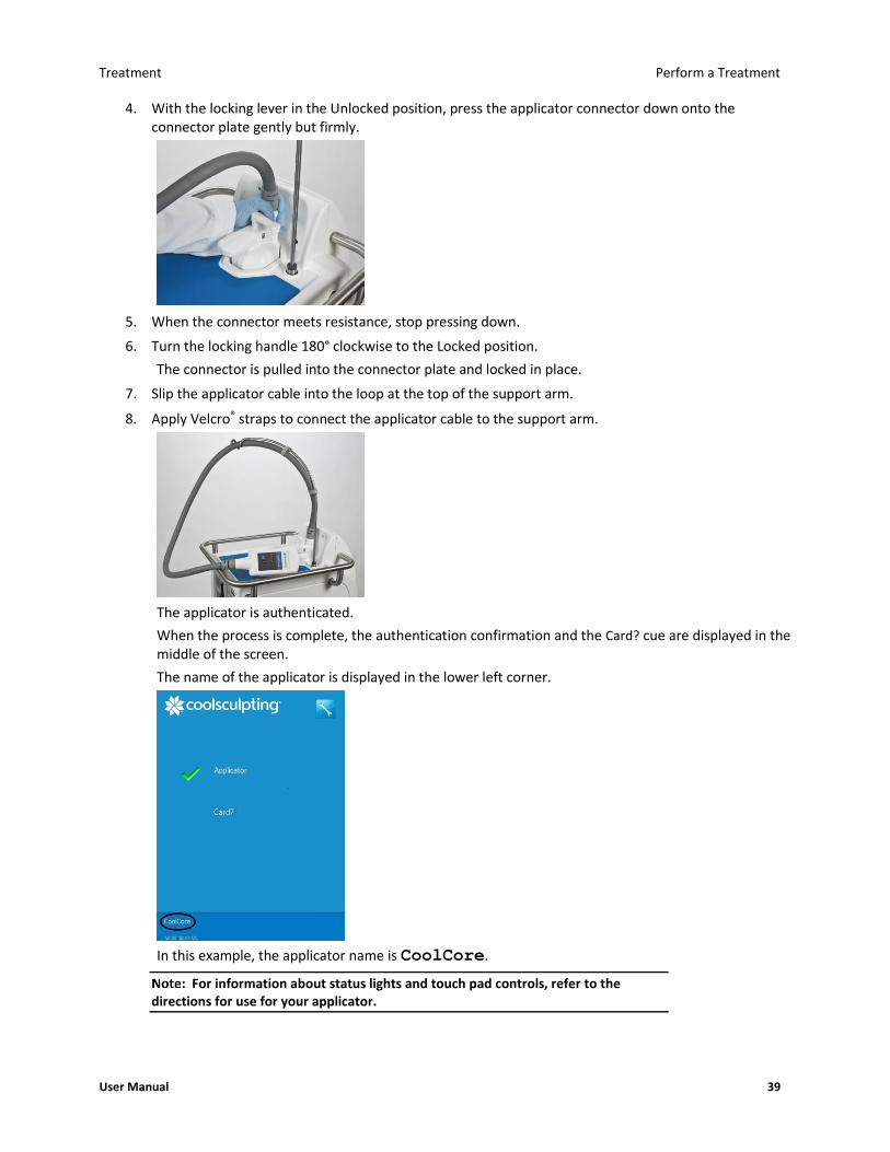
Treatment Perform a Treatment
User Manual 39
4. With the locking lever in the Unlocked position, press the applicator connector down onto the connector plate gently but firmly.
5. When the connector meets resistance, stop pressing down.
6. Turn the locking handle 180° clockwise to the Locked position.
The connector is pulled into the connector plate and locked in place.
7. Slip the applicator cable into the loop at the top of the support arm.
8. Apply Velcro® straps to connect the applicator cable to the support arm.
The applicator is authenticated.
When the process is complete, the authentication confirmation and the Card? cue are displayed in the middle of the screen.
The name of the applicator is displayed in the lower left corner.
In this example, the applicator name is CoolCore.
For information about status lights and touch pad controls, refer to the directions for use for your applicator.

Perform a Treatment Treatment
40 BRZ-101-TUM-EN2-M
Insert a Card
► To insert a card:
1. Align the card to the slot on the applicator.
For CoolAdvantage and CoolMini applicators, insert the card into the slot on the applicator adapter.
2. Insert the card into the slot.
The card is authenticated.
The authentication confirmation and the number of cycles remaining on the card are displayed in the middle of the screen.
The name of the card and the number of cycles remaining are displayed in the lower right corner.
The Next button is displayed.
In this example, the name of the card is CoolCard.
3. Press the Next button.
The New to Practice and Returning to Practice buttons are displayed.
If the patient data controls are not displayed, contact Customer Service.
Enter Patient Data
If the Usage Metrics function has been disabled, the Profile panel is displayed. See Select a Profile on page 41.
► To enter patient data:
1. Press the New to Practice or Returning to Practice button.
2. Press the Female Patient or Male Patient button.
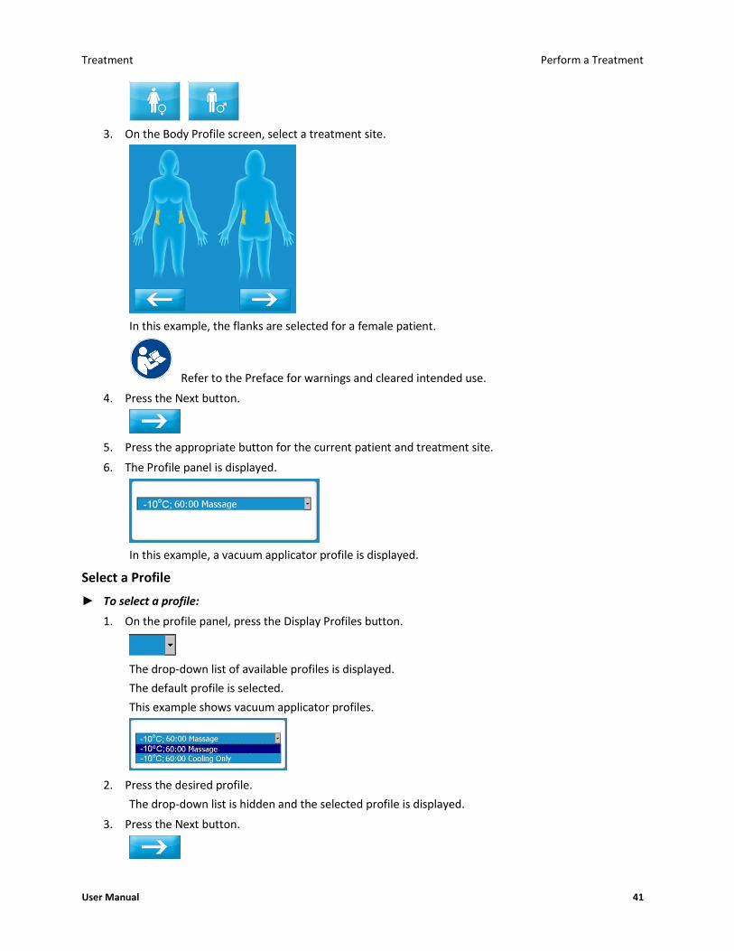
Treatment Perform a Treatment
User Manual 41
3. On the Body Profile screen, select a treatment site.
In this example, the flanks are selected for a female patient.
Refer to the Preface for warnings and cleared intended use.
4. Press the Next button.
5. Press the appropriate button for the current patient and treatment site.
6. The Profile panel is displayed.
In this example, a vacuum applicator profile is displayed.
Select a Profile
► To select a profile:
1. On the profile panel, press the Display Profiles button.
The drop-down list of available profiles is displayed.
The default profile is selected.
This example shows vacuum applicator profiles.
2. Press the desired profile.
The drop-down list is hidden and the selected profile is displayed.
3. Press the Next button.

Perform a Treatment Treatment
42 BRZ-101-TUM-EN2-M
Vacuum Applicator Treatment
• For a CoolAdvantage treatment, see the CoolAdvantage Directions for Use.
• For a CoolMini treatment, see the CoolMini Directions for Use.
If a liner is detected, the GELPAD? button is displayed.
If no liner is detected, the Liner? cue is displayed.
1. Install a liner.
CAUTION: Use a new liner on each patient.
CAUTION: Refer to the directions for use for your liner.
When the system detects the liner, it displays the GELPAD? button.
If the liner is not detected, disconnect the tabs from the hooks. Grasp the frames of the liner and remove the liner from the applicator cup. Repeat the installation process.
► To apply a gelpad:
Inspect the treatment site to ensure that the skin is intact. Treat over intact skin only.
1. Remove jewelry that is in or directly adjacent to the application site.
2. Wipe the treatment site with an alcohol wipe and/or pretreatment skin wipe.
Refer to the directions for use for your gelpad.
3. Press the GELPAD? button.
4. On the Gelpad Ready screen, press the Next button.
The Vacuum panel is displayed.
The Vacuum cue on the lower right spins.
The Vacuum Status light on the applicator touch pad flashes blue.

Treatment Perform a Treatment
User Manual 43
► To apply a vacuum applicator:
The use of this device on areas with superficially located nerve branches, arteries, or veins has not been demonstrated to be safe and effective. Such use may result in injury to the patient.
If the gelpad slips and the cooling surfaces of the applicator come into direct contact with the patient’s skin, tissue injury may result. Inspect the gelpad and applicator to ensure that the gelpad extends beyond the edges of the applicator cup.
Use the default vacuum settings or the lowest settings that result in acceptable tissue draw into the applicator cup.
1. Press the Vacuum On/Off button on the applicator touch pad.
The vacuum is activated.
The Vacuum On button and the Tissue Draw indicator are displayed.
The Vacuum Status light on the applicator touch pad shines blue.
2. Place the applicator over the center of the gelpad on the treatment site.
3. Ensure that the gelpad extends beyond the edges of the applicator cup.
4. For best results, ensure that tissue is drawn into the applicator cup.
5. (Optional: Test Vacuum Pressure for Massage)
6. When the system detects that the applicator is connected to the treatment site, the Start button is displayed.
The Treatment Status light on the applicator touch pad flashes blue.
Press the Start button.
The Treatment Status light on the applicator touch pad shines blue.
Surface Applicator Treatment
The CONFIRM? Site Preparation button is displayed.
Inspect the treatment site to ensure that the skin is intact. Treat over intact skin only.

Perform a Treatment Treatment
44 BRZ-101-TUM-EN2-M
1. Remove jewelry that is in or directly adjacent to the treatment site.
CAUTION: Prepare the treatment site with an alcohol wipe.
2. Apply one pair of foam borders around the treatment site.
CAUTION: Refer to the directions for use for your foam borders.
3. Wipe the treatment site with a pretreatment skin wipe.
4. Apply a gelpad to the treatment site.
Refer to the directions for use for your gelpad.
5. Apply a liner over the gelpad.
CAUTION: Refer to the directions for use for your liner.
6. Press the CONFIRM? Site Preparation button.
7. Press the Next button.
The Surface Applicator Placement Cue is displayed.
► To apply a surface applicator:
The use of this device on areas with superficially located nerve branches, arteries, or veins has not been demonstrated to be safe and effective. Such use may result in injury to the patient.
If the gelpad slips and the cooling surfaces of the applicator come into direct contact with the patient’s skin, tissue injury may result. Inspect the gelpad and liner to ensure that they extend beyond the outside edges of the foam borders.
1. Place the applicator between the foam borders on the treatment site.
2. Ensure that the gelpad and liner extend beyond the outside edges of the foam borders.
3. Wrap the securement system straps around the patient to secure the applicator in place.
Refer to the securement system directions for use for information on securing the applicator in place.
4. Press the Start button.
The Treatment Status light on the applicator shines blue.

Treatment Perform Another Treatment
User Manual 45
Perform Another Treatment
► To perform another treatment on the same patient:
CAUTION: When the vacuum is turned off or the securement system straps are released, the applicator may disengage from the patient. The applicator could fall and be damaged or cause injury. Grasp the head of the applicator firmly before turning off the vacuum or releasing the securement system straps.
Remove a vacuum applicator: Remove a surface applicator:
Grasp the applicator and turn off the vacuum. Grasp the applicator and release the securement system straps.
Remove the applicator from the patient. Remove the applicator from the patient.
Place the applicator head on top of the control unit with the cooling surfaces facing downward.
Place the applicator head on top of the control unit with the cooling surfaces facing upward.
Allow gel to drain onto a towel or other absorbent material.
n/a
Remove the gelpad or gel from the treatment site. Remove the liner, gelpad, and foam borders from the treatment site.
Discard the used gelpad or gel according to your site’s medical waste protocols.
Discard the used liner, gelpad, and foam borders according to your site’s medical waste protocols.
The Same Patient and Next Patient buttons are displayed.
(If the card is expired, see Expired Card on page 46.)
1. Press the Same Patient button.
2. On the Body Profile screen, select a treatment site.
In this example, the lower abdomen is selected for a female patient.
Refer to the Preface for warnings and cleared intended use.

Perform Another Treatment Treatment
46 BRZ-101-TUM-EN2-M
3. Press the Next button.
4. Press the appropriate button for the current patient and treatment site.
The Profile panel is displayed.
• See Select a Profile on page 41.
► To perform a treatment on the next patient:
CAUTION: When the vacuum is turned off or the securement system straps are released, the applicator may disengage from the patient. The applicator could fall and be damaged or cause injury. Grasp the head of the applicator firmly before turning off the vacuum or releasing the securement system straps.
Remove a vacuum applicator: Remove a surface applicator:
Grasp the applicator and turn off the vacuum. Grasp the applicator and release the securement system straps.
Remove the applicator from the patient. Remove the applicator from the patient.
Place the applicator head on top of the control unit with the cooling surfaces facing downward.
Place the applicator head on top of the control unit with the cooling surfaces facing upward.
Allow gel to drain onto a towel or other absorbent material.
n/a
Remove the gelpad or gel from the treatment site. Remove the liner, gelpad, and foam borders from the treatment site.
Remove the liner from the applicator cup. n/a
Discard the used gelpad or gel, and liner according to your site’s medical waste protocols.
Discard the used liner, gelpad, foam borders, and securement system according to your site’s medical waste protocols.
1. If the Same Patient and Next Patient buttons are displayed, press the Next Patient button.
If the Profile panel is displayed, select a profile.
• See Enter Patient Data on page 40.
Expired Card
If the card is expired, a recoverable exception is displayed.
1. Remove the card from the applicator.
2. Press the Next button to clear the message.
3. Insert a new card into the slot on the applicator.
The system authenticates the card.
4. When authentication is complete, press the Next button.
The profile screen is displayed.
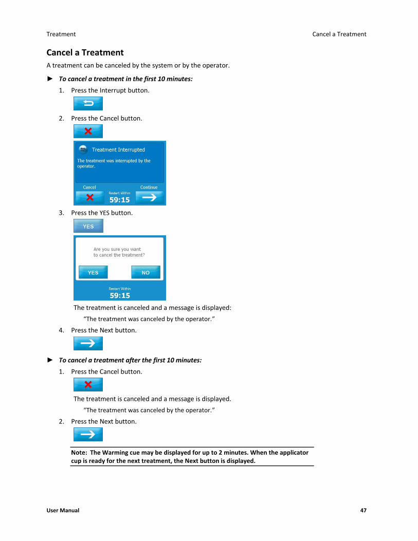
Treatment Cancel a Treatment
User Manual 47
Cancel a Treatment
A treatment can be canceled by the system or by the operator.
► To cancel a treatment in the first 10 minutes:
1. Press the Interrupt button.
2. Press the Cancel button.
3. Press the YES button.
The treatment is canceled and a message is displayed:
“The treatment was canceled by the operator.”
4. Press the Next button.
► To cancel a treatment after the first 10 minutes:
1. Press the Cancel button.
The treatment is canceled and a message is displayed.
“The treatment was canceled by the operator.”
2. Press the Next button.
The Warming cue may be displayed for up to 2 minutes. When the applicator cup is ready for the next treatment, the Next button is displayed.

About Restarting a Treatment Treatment
48 BRZ-101-TUM-EN2-M
About Restarting a Treatment
A treatment can be interrupted by either the operator or the system. When you restart a treatment, the treatment count on the card is not reduced further.
Each treatment can be restarted only once.
A treatment can be restarted if:
• The operator interrupted the treatment during the first 10 minutes
• The system interrupted the treatment during the first 10 minutes with one of the following Recoverable Exceptions:
The coolant level is low. Z403-YYY
Applicator control error. Z408-YYY
Treatment quality error. Z412-YYY
Potential loss of patient contact. Z415-YYY
Interference detected. Z426-YYY
• And, the Restart timer interval of 60 minutes has not expired
Interrupt a Treatment
► To interrupt a treatment:
1. Press the Interrupt button.
The Treatment Interrupted screen is displayed.
The Restart Timer runs for up to 60 minutes, after which the treatment can no longer be restarted.
2. Press the Next button to continue.
The Warming cue may be displayed for up to 2 minutes. When the applicator cup is ready for the next treatment, the Next button is displayed.
Treatment Complete a Treatment
User Manual 49
Restart a Treatment
CAUTION: When the vacuum is turned off or the securement system straps are released, the applicator may disengage from the patient. The applicator could fall and be damaged or cause injury. Grasp the head of the applicator firmly before turning off the vacuum or releasing the securement system straps.
The patient data that was used to start the treatment will be used to complete the treatment.
► To restart a treatment:
Remove a vacuum applicator: Remove a surface applicator:
Grasp the applicator and turn off the vacuum. Grasp the applicator and release the securement system straps.
Remove the applicator from the patient. Remove the applicator from the patient.
Place the applicator head on top of the control unit with the cooling surfaces facing downward.
Place the applicator head on top of the control unit with the cooling surfaces facing upward.
Allow gel to drain onto a towel or other absorbent material.
n/a
Remove the gelpad or gel from the treatment site. Remove the liner and gelpad from the treatment site.
Discard the used gelpad or gel according to your site’s medical waste protocols.
Discard the used liner and gelpad according to your site’s medical waste protocols.
• See Vacuum Applicator Treatment on page 42.
• See Surface Applicator Treatment on page 43.
Complete a Treatment
► To complete a treatment:
When the treatment is complete, a message is displayed.
“The treatment is complete.”
CAUTION: When the vacuum is turned off or the securement system straps are released, the applicator may disengage from the patient. The applicator could fall and be damaged or cause injury. Grasp the head of the applicator firmly before turning off the vacuum or releasing the securement system straps.
Remove a vacuum applicator: Remove a surface applicator:
Grasp the applicator and turn off the vacuum. Grasp the applicator and release the securement system straps.
Remove the applicator from the patient. Remove the applicator from the patient.
Place the applicator head on top of the control unit with the cooling surfaces facing downward.
Place the applicator head on top of the control unit with the cooling surfaces facing upward.
Allow gel to drain onto a towel or other absorbent material.
n/a

Complete a Treatment Treatment
50 BRZ-101-TUM-EN2-M
Remove a vacuum applicator: Remove a surface applicator:
Remove the gelpad or gel from the treatment site. Remove the liner, gelpad, and foam borders from the treatment site.
Remove the liner from the applicator cup. n/a
Discard the used gelpad or gel, and liner according to your site’s medical waste protocols.
Discard the used liner, gelpad, foam borders, and securement system according to your site’s medical waste protocols.
1. Wipe gel from the patient’s skin.
2. Wipe the cooling surfaces of the applicator with a soft, dry cloth.
3. To power off the control unit, press the power switch.
CAUTION: The electronic sensors on the cooling surfaces of the applicator are delicate. Use care when cleaning and storing the applicator. (See Cleaning on page 53.)
Test Vacuum Pressure for Massage
(Standard vacuum applicators only) Before you start a treatment, you can test and modify the vacuum pressure for massage to ensure that the vacuum pressure is high enough to keep the applicator in place during the treatment.
► To test the vacuum pressure for massage:
1. When the applicator is on the treatment site and the tissue is drawn into the applicator cup, press the Display Massage Settings button.
The Massage Settings Panel is displayed.
2. Press the Massage Status (Off) button on the Massage Settings panel.
3. Press the Max and Min Increase and Decrease buttons on the Massage Settings panel if needed to modify vacuum pressure for massage.
4. Press the Massage Status (On) button to turn off massage.
5. Press the Hide Massage Settings button.

Treatment Complete a Treatment
User Manual 51
6. If necessary, adjust the position of the vacuum applicator and modify the vacuum pressure for massage.
7. If you turn off the vacuum and then remove the vacuum applicator from the site:
a) Discard the used gelpad or gel according to your site’s medical waste protocols.
b) Clean the treatment site.
c) Apply a new gelpad or new gel. (Refer to the Directions for Use for your gelpad.)

Complete a Treatment Treatment
52 BRZ-101-TUM-EN2-M
This page intentionally left blank.
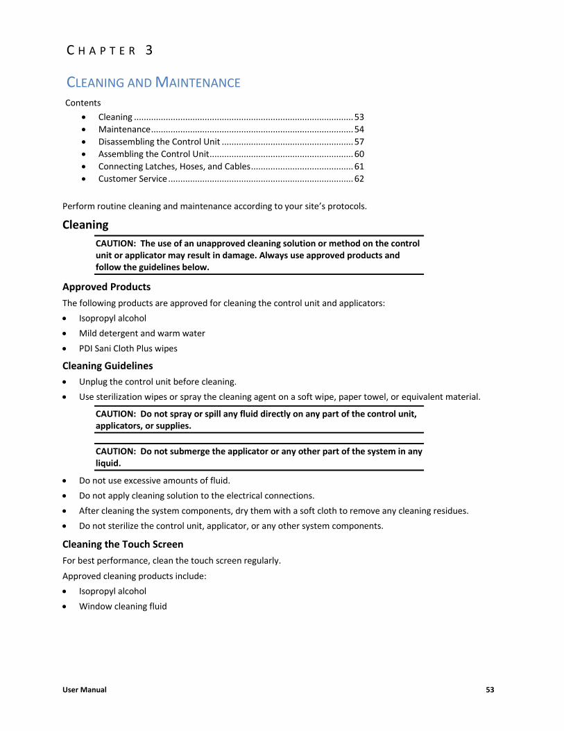
User Manual 53
Contents
• Cleaning .......................................................................................... 53
• Maintenance ................................................................................... 54
• Disassembling the Control Unit ...................................................... 57
• Assembling the Control Unit ........................................................... 60
• Connecting Latches, Hoses, and Cables .......................................... 61
• Customer Service ............................................................................ 62
Perform routine cleaning and maintenance according to your site’s protocols.
Cleaning
CAUTION: The use of an unapproved cleaning solution or method on the control unit or applicator may result in damage. Always use approved products and follow the guidelines below.
Approved Products
The following products are approved for cleaning the control unit and applicators:
• Isopropyl alcohol
• Mild detergent and warm water
• PDI Sani Cloth Plus wipes
Cleaning Guidelines
• Unplug the control unit before cleaning.
• Use sterilization wipes or spray the cleaning agent on a soft wipe, paper towel, or equivalent material.
CAUTION: Do not spray or spill any fluid directly on any part of the control unit, applicators, or supplies.
CAUTION: Do not submerge the applicator or any other part of the system in any liquid.
• Do not use excessive amounts of fluid.
• Do not apply cleaning solution to the electrical connections.
• After cleaning the system components, dry them with a soft cloth to remove any cleaning residues.
• Do not sterilize the control unit, applicator, or any other system components.
Cleaning the Touch Screen
For best performance, clean the touch screen regularly.
Approved cleaning products include:
• Isopropyl alcohol
• Window cleaning fluid
C H A P T E R 3
CLEANING AND MAINTENANCE

Maintenance Cleaning and Maintenance
54 BRZ-101-TUM-EN2-M
► To clean the touch screen:
1. Dampen a soft lint-free cloth with isopropyl alcohol or a window cleaning fluid.
2. Wipe the touch screen gently.
Maintenance
External Chiller Filter
The CoolSculpting control unit has an external filter installed that is located on the front bottom of the system (Picture A) and is easily replaceable. The purpose of this filter is to extend the service life of your control unit.
► Location of filter (Picture A):
► When to replace:
Every 6 months or
Blue Thermometer icon appears for extended period of time:
(Picture B)

Cleaning and Maintenance Preventive Maintenance
User Manual 55
► How to replace the external chiller filter:
Turn the control unit off prior to replacing the filter
Preventive Maintenance
As a rule, replace the chiller filter every six months. However, if the cooling cue (blue thermometer) is displayed indefinitely, or if the Z802-322 Chiller Error message is displayed, replace the chiller filter promptly. ► To replace the external chiller filter: 1. Slide the filter out of the slot.
2. Pull the filter downward to slip it out from under the spring. 3. Discard the used filter. 4. Remove a new filter from the package. 5. Slide the bottom of the new filter into the slot.
6. Fold the front of the filter up under the spring.
7. Ensure that the front of the filter is fitted smoothly against the frame.
► How to order:
The replacement part number is FRU-CTU-BAM-103 and can be ordered by contacting your local Allergan office.

Preventive Maintenance Cleaning and Maintenance
56 BRZ-101-TUM-EN2-M
Coolant
Coolant circulates between the control unit and the applicator to remove heat from the applicator. When you connect a new applicator, it takes up a significant amount of coolant. Also, when you disconnect an applicator, or disconnect the hoses on the access panel to prepare for shipping a module, a small amount of coolant may be lost.
When the level of coolant is low, the control unit displays a message. It is safe to add coolant while the control unit is powered on.
CAUTION: The use of unauthorized coolant has not been tested. Always use coolant authorized by ZELTIQ.
► To add coolant:
1. Locate the chiller tank cap.
2. Press down on the recessed end of the blue lever on the chiller tank cap.
The handle flips up.
3. Turn the blue handle counter-clockwise until the cap disengages.
4. Remove the cap.
5. Pour coolant into the tank.

Cleaning and Maintenance Disassembling the Control Unit
User Manual 57
The amount of additional coolant that is required can vary. To avoid spillage, watch the coolant as you pour. Listen for changes in the sound.
6. Replace the cap and tighten it just until snug.
When the vacuum is activated, it pulls the cap in tighter. If you overtighten the cap, it could become too tight to loosen.
Disassembling the Control Unit
The control unit consists of an upper module and a base module. Disassemble the control unit to prepare to ship either module to the factory for repair or replacement.
CAUTION: The upper and base modules of the control unit are heavy. Do not attempt to lift either module by yourself. This procedure requires two people.
Latches
► To disassemble the control unit:
1. Power off the control unit.
2. Engage the locks on all four casters.
3. Disconnect the power cord from the control unit.
4. Wrap the power cord around the cleats and secure it with the Velcro® strap.
5. Open the storage drawer and disconnect the latches on the front of the control unit.
6. Disconnect the latches on the back of the control unit.
► To disconnect a latch:

Disassembling the Control Unit Cleaning and Maintenance
58 BRZ-101-TUM-EN2-M
1. Flip the handle of the latch upward and turn it counterclockwise until the top of the clasp disengages.
2. Pull the handle back and let it hang downward.
Cables and Hoses
► To disconnect cables and hoses:
1. Turn the thumbscrew on the cover of the access panel.
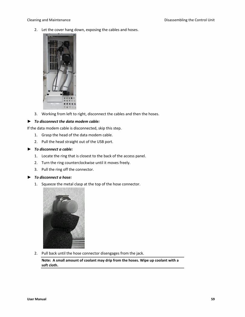
Cleaning and Maintenance Disassembling the Control Unit
User Manual 59
2. Let the cover hang down, exposing the cables and hoses.
3. Working from left to right, disconnect the cables and then the hoses.
► To disconnect the data modem cable:
If the data modem cable is disconnected, skip this step.
1. Grasp the head of the data modem cable.
2. Pull the head straight out of the USB port.
► To disconnect a cable:
1. Locate the ring that is closest to the back of the access panel.
2. Turn the ring counterclockwise until it moves freely.
3. Pull the ring off the connector.
► To disconnect a hose:
1. Squeeze the metal clasp at the top of the hose connector.
2. Pull back until the hose connector disengages from the jack.
A small amount of coolant may drip from the hoses. Wipe up coolant with a soft cloth.
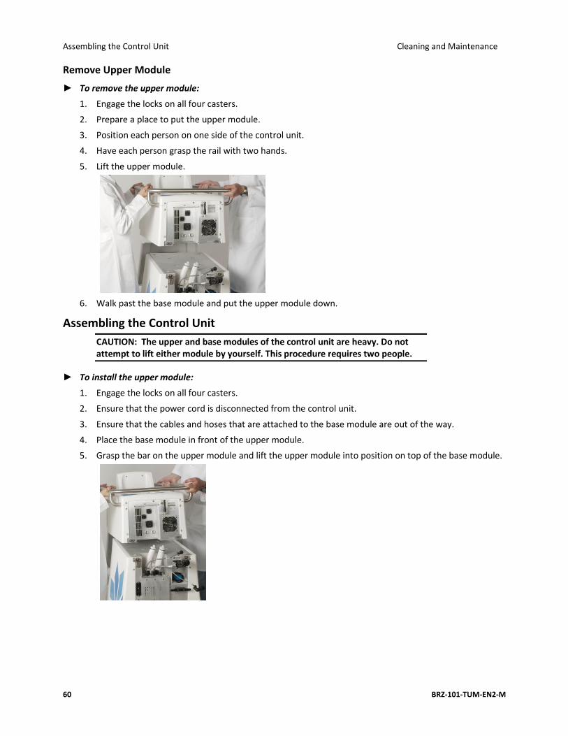
Assembling the Control Unit Cleaning and Maintenance
60 BRZ-101-TUM-EN2-M
Remove Upper Module
► To remove the upper module:
1. Engage the locks on all four casters.
2. Prepare a place to put the upper module.
3. Position each person on one side of the control unit.
4. Have each person grasp the rail with two hands.
5. Lift the upper module.
6. Walk past the base module and put the upper module down.
Assembling the Control Unit
CAUTION: The upper and base modules of the control unit are heavy. Do not attempt to lift either module by yourself. This procedure requires two people.
► To install the upper module:
1. Engage the locks on all four casters.
2. Ensure that the power cord is disconnected from the control unit.
3. Ensure that the cables and hoses that are attached to the base module are out of the way.
4. Place the base module in front of the upper module.
5. Grasp the bar on the upper module and lift the upper module into position on top of the base module.

Cleaning and Maintenance Connecting Latches, Hoses, and Cables
User Manual 61
6. Ensure that the cables and hoses are clear.
7. Connect the latches, cables, and hoses.
8. Ensure that the upper module is aligned to the base module.
Connecting Latches, Hoses, and Cables
► To connect a latch:
1. Place the top clasp over the top hook.
2. Flip the handle of the latch outward.
3. Turn the handle clockwise until the top clasp is snug against the hook.
4. Press the handle down.
► To connect the hoses and cables:
1. Start with the hose on the right.
2. Press the hose into the jack.
3. Repeat for the hose on the left.
4. Press the cable connector on the right over the post.
5. Turn the ring clockwise until it is snug. Do not overtighten.
6. Repeat for the remaining cables, working from right to left.
7. Close the cover of the access panel.
8. Align the thumbscrew on the cover of the access panel to the hole on the upper module.
9. Turn the thumbscrew to the right just until it is snug. Do not overtighten.

Customer Service Cleaning and Maintenance
62 BRZ-101-TUM-EN2-M
► To connect the data modem cable:
1. Grasp the head of the data modem cable.
2. Ensure that the USB symbol is facing upward.
3. Insert the head of the cable into the upper USB port.
Customer Service
To report issues with the performance or use of your System, contact ZELTIQ Customer Service.
• Worldwide: (+1) 925-474-8160
• United States: 1-888-935-8471 (1-888-ZELTIQ1)
Routine Issues
For questions regarding device performance or to report issues that do not interfere with current patient treatments:
• Call during regular business hours, 6 am to 6 pm, Pacific Time, Monday through Friday. Calls are answered in the order received.
Urgent Issues
To report safety concerns or issues that interfere with current patient treatments: Call at any time. Outside regular business hours (above), leave a voicemail. A technician will be paged and
will return your call promptly.
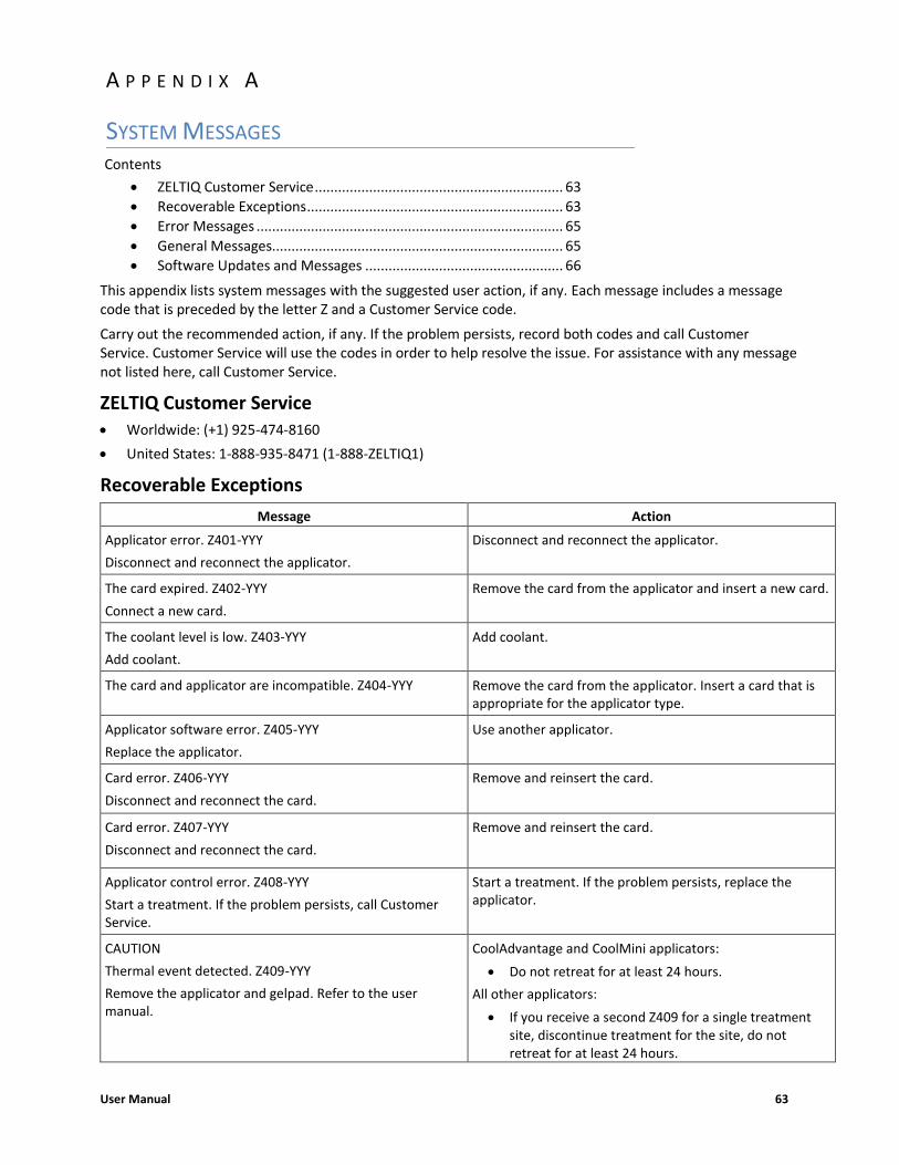
User Manual 63
Contents
• ZELTIQ Customer Service ................................................................ 63
• Recoverable Exceptions .................................................................. 63
• Error Messages ............................................................................... 65
• General Messages........................................................................... 65
• Software Updates and Messages ................................................... 66
This appendix lists system messages with the suggested user action, if any. Each message includes a message code that is preceded by the letter Z and a Customer Service code.
Carry out the recommended action, if any. If the problem persists, record both codes and call Customer Service. Customer Service will use the codes in order to help resolve the issue. For assistance with any message not listed here, call Customer Service.
ZELTIQ Customer Service • Worldwide: (+1) 925-474-8160
• United States: 1-888-935-8471 (1-888-ZELTIQ1)
Recoverable Exceptions
Message Action
Applicator error. Z401-YYY
Disconnect and reconnect the applicator.
Disconnect and reconnect the applicator.
The card expired. Z402-YYY
Connect a new card.
Remove the card from the applicator and insert a new card.
The coolant level is low. Z403-YYY
Add coolant.
Add coolant.
The card and applicator are incompatible. Z404-YYY Remove the card from the applicator. Insert a card that is appropriate for the applicator type.
Applicator software error. Z405-YYY
Replace the applicator.
Use another applicator.
Card error. Z406-YYY
Disconnect and reconnect the card.
Remove and reinsert the card.
Card error. Z407-YYY
Disconnect and reconnect the card.
Remove and reinsert the card.
Applicator control error. Z408-YYY
Start a treatment. If the problem persists, call Customer Service.
Start a treatment. If the problem persists, replace the applicator.
CAUTION
Thermal event detected. Z409-YYY
Remove the applicator and gelpad. Refer to the user manual.
CoolAdvantage and CoolMini applicators:
• Do not retreat for at least 24 hours.
All other applicators:
• If you receive a second Z409 for a single treatment site, discontinue treatment for the site, do not retreat for at least 24 hours.
A P P E N D I X A
SYSTEM MESSAGES

Recoverable Exceptions System Messages
64 BRZ-101-TUM-EN2-M
Message Action
Applicator control error. Z410-YYY
Start a treatment. If the problem persists, call Customer Service.
Start a treatment. If the problem persists, call Customer Service.
Applicator error. Z411-YYY
Power the control unit off and on.
Power the control unit off and on.
Treatment quality error. Z412-YYY
Start a treatment. If the problem persists, call Customer Service.
Restart the treatment or start a new treatment.
Applicator error. Z414-YYY
Disconnect and reconnect the applicator.
Disconnect and reconnect the applicator.
Potential loss of patient contact. Z415-YYY
Reapply the applicator and start a treatment. If the problem persists, call Customer Service.
Turn off the vacuum, remove the applicator cup from the patient, discard the used gelpad or gel, clean the treatment site, and apply a new gelpad or new gel. Restart an interrupted treatment or start a new treatment.
Card compatibility error. Z417-YYY
Replace the card.
Insert a card that is compatible with the control unit.
Card compatibility error. Z418-YYY
Call Customer Service.
Call Customer Service.
Card compatibility error. Z420-YYY
Call Customer Service.
Call Customer Service.
Card error. Z421-YYY
Disconnect and reconnect the card.
Disconnect and reconnect the card.
Disconnect and reconnect the applicator. Z422-YYY Disconnect and reconnect the applicator.
The restart timer has expired. Z425-YYY
Start a new treatment.
Start a new treatment.
Interference detected. Z426-YYY
Start a treatment. If the problem persists, refer to the User Manual.
Identify and resolve possible causes:
• Patient movement
• Another medical device in close proximity
If the problem persists, contact Customer Service.
This system must be serviced by ZELTIQ no later than YYYY-MM-DD to ensure continued use. Z428-YYY
Contact Customer Service.
The applicator adapter and applicator are incompatible. Z429-YYY. Contact Customer Service.
Contact Customer Service.
Table 15: Recoverable Exceptions

System Messages Error Messages
User Manual 65
Error Messages
For all system errors, power the control unit off and on. If the problem persists, call Customer Service. (ZELTIQ Customer Service on page 61)
Code Message
Z801 Chiller error. Z801-YYY
Z802 Chiller error. Z802-YYY
Z803 Control unit error. Z803-YYY
Z804 Control unit error. Z804-YYY
Z805 Control unit error. Z805-YYY
Z806 Invalid configuration values. Z806-YYY
Z808 Software error. Z808-YYY
Z809 Control unit error. Z809-YYY
Z810 This system must be serviced by ZELTIQ. Contact Customer Service.
Z811 Control unit error. Z811-YYY
Z812 The device connected to the control unit is not recognized. Z812-YYY
Table 16: Error Messages
General Messages
Message Recommended Action
The applicator is disconnected. Connect the applicator to the control unit.
The card is disconnected. Insert the card into the slot on the applicator. Ensure that the card is inserted correctly.
The treatment was cancelled by the operator. Restart the treatment or start a new treatment.
The treatment is complete. Turn off vacuum, remove the applicator and gelpad or gel, and clean the treatment site.
The treatment was interrupted by the operator. Restart the treatment or start a new treatment.
Turn off the vacuum.
Remove the applicator and gelpad or gel.
Turn off vacuum power either on the applicator touch pad or on the system touch screen. Remove the applicator and gelpad or gel.
Are you sure you want to cancel the treatment? Press the YES button to cancel the current treatment. Press the NO button to continue and restart the current treatment.
Table 17: General Messages

Software Updates and Messages System Messages
66 BRZ-101-TUM-EN2-M
Software Updates and Messages
From time to time, ZELTIQ may provide software updates.
Button Description Name
A software update is available. Software Update
Install the software update. Install
Clear the software update code. Clear
Delete the last character of the patient number. Backspace
Postpone the software update. Postpone
Start the update. Next Update
Skip the update. Skip Update
Table 18: Controls and Cues for Software Updates
The following text and messages may be displayed.
Software Update
Approximate installation time: xx minutes
Installation must be performed no later than YYYY/MM/DD to ensure continued use.
Enter the Software Update Key.
Installation complete.
Press the Next button.
Installation error. Z930
Power the control unit off and on. If the problem persists, contact Customer Service.
Installation error. Z961-YYY
Remove the USB stick. Power the control unit off and on. Contact Customer Service.
Installation error. Z962-YYY
Press the Next button. Contact Customer Service.
Installation error. Z963
Power the control unit off and on. If the problem persists, contact Customer Service.
Table 19: Software Update Installation Messages

System Messages Software Updates and Messages
User Manual 67
CoolAdvantage Software Updates and Messages
In addition to the general software update messages, the following information may be displayed during a CoolAdvantage software update.
Software Update: Attach the applicator adapter to the control unit. Approximate installation time: xx minutes
Installation must be performed no later than YYYY/MM/DD to ensure continued use.
Software updating ........
Installation complete. Press the Next button.
The applicator adapter was not detected. If you have an adapter, connect it to the control unit. To proceed with the update, press the Next button. To skip the update, press the Skip button.
Table 20: CoolAdvantage Software Update Installation Messages

Software Updates and Messages System Messages
68 BRZ-101-TUM-EN2-M
This page intentionally left blank.
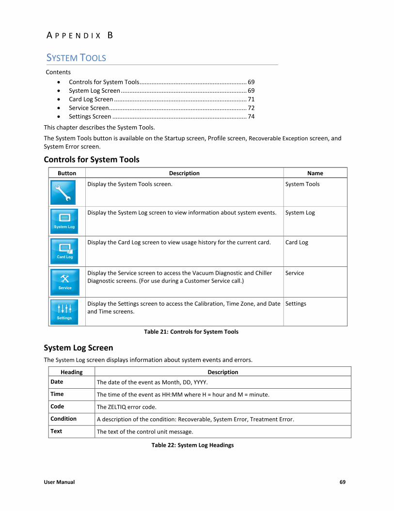
User Manual 69
Contents
• Controls for System Tools ............................................................... 69
• System Log Screen .......................................................................... 69
• Card Log Screen .............................................................................. 71
• Service Screen ................................................................................. 72
• Settings Screen ............................................................................... 74
This chapter describes the System Tools.
The System Tools button is available on the Startup screen, Profile screen, Recoverable Exception screen, and System Error screen.
Controls for System Tools
Button Description Name
Display the System Tools screen. System Tools
Display the System Log screen to view information about system events. System Log
Display the Card Log screen to view usage history for the current card. Card Log
Display the Service screen to access the Vacuum Diagnostic and Chiller Diagnostic screens. (For use during a Customer Service call.)
Service
Display the Settings screen to access the Calibration, Time Zone, and Date and Time screens.
Settings
Table 21: Controls for System Tools
System Log Screen
The System Log screen displays information about system events and errors.
Heading Description
Date The date of the event as Month, DD, YYYY.
Time The time of the event as HH:MM where H = hour and M = minute.
Code The ZELTIQ error code.
Condition A description of the condition: Recoverable, System Error, Treatment Error.
Text The text of the control unit message.
Table 22: System Log Headings
A P P E N D I X B
SYSTEM TOOLS

System Log Screen System Tools
70 BRZ-101-TUM-EN2-M
► To view the System Log screen:
1. On the System Tools screen, press the System Log button.
The System Log screen is displayed.
2. To scroll through the screen, drag the slider at the bottom or right side of the screen.
3. To return to the System Tools screen, press the Previous button.
Availability and use of the data modem are subject to regional limitations. The Upload Data button is displayed only if the modem is activated.
The data upload function is for use during a call with customer service.
► To upload data to ZELTIQ:
1. On the System Log screen, press the Upload Data button.
The Upload Status screen is displayed.
When the process is complete, a message is displayed:
Upload Status: Uploading, Upload complete, Upload failed

System Tools Card Log Screen
User Manual 71
Card Log Screen
The Card Log screen displays information about card usage. View the Card Log screen when you have questions about the number of cycles remaining and when treatments were performed.
Heading Description
Date The date of the usage: Month, DD, YYYY.
Time The time of the usage as HH:MM, where H = hour and M = minute, in AM/PM.
Status The status of the usage: (Canceled, Error, Unknown, Successful)
Table 23: Card Log Headings
► To view the Card Log screen:
1. Attach the applicator to the control unit.
2. Insert the card into the slot on the applicator.
The control unit authenticates the card.
3. When the process is complete, press the Next button.
4. On the System Tools screen, press the Card Log button.
The Card Log screen is displayed.
5. To return to the System Tools screen, press the Previous button.

Service Screen System Tools
72 BRZ-101-TUM-EN2-M
Service Screen
Controls for Service Tools
The tools on the Service screen are for use during a call with Customer Service. Follow the instructions provided by Customer Service.
Button Description Name
Display the Vacuum Diagnostic screen to view information about the performance of the vacuum system.
Vacuum Diagnostic
Display the Chiller Diagnostic screen to view information about the performance of the chiller.
Chiller Diagnostic
The data modem can upload data to ZELTIQ. Availability and use of the data modem are subject to regional limitations.
Data Modem
Table 24: Controls for Service Tools
► To view the Service screen:
1. On the System Tools screen, press the Service button.
The Service screen is displayed.
Vacuum Diagnostic Screen
The Vacuum Diagnostic screen provides information about the performance of the vacuum system.
Any changes to settings on this screen are temporary and do not influence the functionality of the system during a treatment.
► To view the Vacuum Diagnostic screen:
1. On the Service screen, press the Vacuum Diagnostic button.

System Tools Service Screen
User Manual 73
The Vacuum Diagnostic screen is displayed.
Standard Vacuum Applicator Vacuum Applicator with Adapter
On the sample screens, the applicator is disconnected and vacuum power is off.
2. Follow the instructions provided by Customer Service.
3. To return to the System Tools screen, press the Previous button.
Chiller Diagnostic Screen
The Chiller Diagnostic screen provides information about the performance of the chiller.
Any changes to settings on this screen are temporary and do not influence the functionality of the system during a treatment.
► To view the Chiller Diagnostic screen:
1. On the Service screen, press the Chiller Diagnostic button.
The Chiller Diagnostic screen is displayed.
On the sample screen, the applicator is connected, the chiller is off, chiller power is off, and cooling is off.
2. Follow the instructions provided by Customer Service.
3. To return to the System Tools screen, press the Previous button.

Settings Screen System Tools
74 BRZ-101-TUM-EN2-M
Data Modem Screen
Availability and use of the data modem are subject to regional limitations. Contact customer service for further information.
► To view the Data Modem screen:
1. On the Service screen, press the Data Modem button.
The Data Modem screen is displayed.
On the sample screen, the Network Type is HSDPA_3G and the Connection Quality is Unknown.
2. Follow the instructions provided by Customer Service.
To return to the Service screen, press the Previous button.
Settings Screen
The Settings button is available on the System Tools screen.
Ensure that the Time Zone setting is correct before you update the Date and Time settings.
Controls for Settings Tools
► To view the Settings screen:
1. On the System Tools screen, press the Settings button.

System Tools Settings Screen
User Manual 75
The Settings screen is displayed.
2. To return to the System Tools screen, press the Previous button.
Calibration Screen
The system screen might require recalibration from time to time. If the screen does not respond accurately to your touch, calibrate the screen.
► To calibrate the screen:
1. On the System Tools screen, press the Settings button.
2. Press the Calibration button.
The Calibration screen is displayed.
3. Use a cotton swab to press the cross-hatch.
The system records your touch and moves the cross-hatch to the next position.
4. Press the cross-hatch in each position.
After you press the last setting, the system displays a message.
5. To save your new settings, touch the screen within the time displayed in the message.
The new settings are saved and the Settings screen is displayed.

Settings Screen System Tools
76 BRZ-101-TUM-EN2-M
6. To discard your new settings and retain the previous settings, wait until the time runs out, approximately 30 seconds.
The Settings screen is displayed.
Time Zone Screen
The setting on the Time Zone screen determines the time zone for entries on the Card Log screen and System
Log screen.
Always check the Date and Time settings after you modify the time zone.
► To modify the time zone:
1. On the Settings screen, press the Time Zone button.
The Time Zone screen displays a list of regions.
2. To select a region, press the name of the region and then press the Next button.
The Time Zone screen displays a list of zones within the region you selected.
3. To scroll through the list, press and drag the scroll panel on the right.
4. To select a time zone, press a row.
5. To save changes, press the Next button.
6. To discard changes, press the Cancel button.

System Tools Settings Screen
User Manual 77
7. On the Settings screen, press the Date & Time button.
Date and Time Screen
Ensure that the Time Zone setting is correct before you modify Date and Time settings.
► To modify date and time settings:
1. On the Settings screen, press the Date & Time button.
The Date and Time screen is displayed.
2. To modify settings, press the Decrease and Increase buttons.
3. To save changes, press the Next button.
4. To discard changes, press the Cancel button.
The Settings screen is displayed.
The 24 Hour setting controls the hour of the day and is in a 24-hour format.
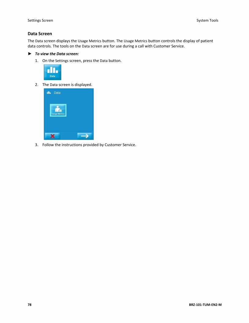
Settings Screen System Tools
78 BRZ-101-TUM-EN2-M
Data Screen
The Data screen displays the Usage Metrics button. The Usage Metrics button controls the display of patient data controls. The tools on the Data screen are for use during a call with Customer Service.
► To view the Data screen:
1. On the Settings screen, press the Data button.
2. The Data screen is displayed.
3. Follow the instructions provided by Customer Service.

User Manual 79
Contents
• Essential Performance .................................................................... 79
• Disposal of Hazardous Materials .................................................... 79
• Environmental Requirements ......................................................... 79
• Electrical Specifications .................................................................. 80
• Medical Safety Standards ............................................................... 80
• Electromagnetic Compatibility ....................................................... 80
• Data Modem Specifications ............................................................ 84
This product may contain remanufactured parts or parts that have had incidental use, all of which are equivalent in performance to new parts.
Essential Performance
When cooling to a target temperature that is below 5°C, the device allows cooling to no more than 1°C below the target temperature. When warming to a target temperature that is above 30°C, the device allows warming to no more than 1°C above the target temperature. Under steady state conditions, the device controls vacuum pressure to within ± 1 inches of Hg.
Disposal of Hazardous Materials
Various components of the system may contain materials whose disposal is subject to regulation. The upper module of the system contains a lithium battery, which is not serviceable by the customer. Dispose of all components of the system in accordance with applicable regulations. Contact your local environmental control agency for additional information on recycling or disposing of the system in your area.
Environmental Requirements
The system and its components are designed to operate normally when stored, shipped, and operated under the following conditions.
Use of the system in an oxygen-rich environment may cause fire. Do not use the system in an oxygen-rich environment.
CAUTION: The system may not operate as expected if it is stored or operated in conditions of excessive heat, humidity, or atmospheric pressure. Operate and store the system in a room that meets the stated requirements.
Shipping / Storage Operating
Temperature 32°F to 140°F (0°C - 60°C) 59°F to 82°F (15°C - 28°C)
Humidity 10% to 95% (non-condensing) 10% to 70% (non-condensing)
Atmospheric Pressure 14.7 psi (101.33 kPa) to 10.1 psi (69.64 kPa).
14.7 psi (101.33 kPa) to 10.1 psi (69.64 kPa).
Table 25: Shipping, Storage, and Operating Requirements
A P P E N D I X C
SYSTEM SPECIFICATIONS

Electrical Specifications System Specifications
80 BRZ-101-TUM-EN2-M
Dimensions of the Control Unit and Modules
Height Depth Width Weight
Control unit alone 47.5 in 120.7 cm
35 in 88.9 cm
24 in 61 cm
215 lbs 97.5 kg
Control unit with support arm 62 in 157.5 cm
n/a n/a 216 lbs 98.0 kg
Upper module 17 in 43.2 cm
27.25 in 69.2 cm
21.25 in 54 cm
65 lbs 29.5 kg
Base module 30.5 in 77.5 cm
28.5 in 72.4 cm
24 in 61 cm
150 lbs 68.0 kg
Table 26: Control Unit - Dimensions
Electrical Specifications
Electrical Safety
Class I Equipment, single phase AC, Continuous Operation
Contains Type BF Patient-applied Parts
Water Ingress Protection: Ordinary Equipment, IPX0
REF Voltage Frequency Current
BRZ-CG1-BAM-100 100VAC 50-60 Hz 12A
BRZ-CG1-BAM-110 110-120VAC 50-60 Hz 12A
BRZ-CG1-BAM-220 220-240VAC 50-60 Hz 7A
Table 27: Electrical Specifications
Fuses
The system contains two internal fuses: Type 3AB (ceramic cartridge), Rating: 250VAC, 6.25A, Slo-Blo. The fuses are not serviceable by the customer.
Medical Safety Standards
The system complies with the following medical safety standards:
• IEC 60601-1: 1998 + A1, A2
• IEC 60601-1: 2005 + CORR. 1 (2006) + CORR. 2 (2007) + Amendment 1:2012
• EN 60601-1: 2006 + Amendment 1:2013
• CAN/CSA C22.2 No 60601.1: 08
• ANSI/AAMI ES 60601-1: 2005 / AS: 2010 + Amendment 1:2012
• AS/NZS IEC 60601.1:2015
• Electromagnetic Compatibility (EMC) EN 60601-1-2: 2015
Electromagnetic Compatibility
The system has been tested and found to comply with Medical Standard Electromagnetic Compatibility (EMC) EN 60601-1-2: 2015. The system complies with the standards outlined below.
This system requires special precautions to ensure electromagnetic compatibility with other electrical medical devices. To ensure EMC, the system must be installed and operated according to the information provided in this manual.
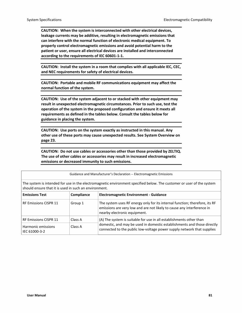
System Specifications Electromagnetic Compatibility
User Manual 81
CAUTION: When the system is interconnected with other electrical devices, leakage currents may be additive, resulting in electromagnetic emissions that can interfere with the normal function of electronic medical equipment. To properly control electromagnetic emissions and avoid potential harm to the patient or user, ensure all electrical devices are installed and interconnected according to the requirements of IEC 60601-1-1.
CAUTION: Install the system in a room that complies with all applicable IEC, CEC, and NEC requirements for safety of electrical devices.
CAUTION: Portable and mobile RF communications equipment may affect the normal function of the system.
CAUTION: Use of the system adjacent to or stacked with other equipment may result in unexpected electromagnetic circumstances. Prior to such use, test the operation of the system in the proposed configuration and ensure it meets all requirements as defined in the tables below. Consult the tables below for guidance in placing the system.
CAUTION: Use ports on the system exactly as instructed in this manual. Any other use of these ports may cause unexpected results. See System Overview on page 23.
CAUTION: Do not use cables or accessories other than those provided by ZELTIQ. The use of other cables or accessories may result in increased electromagnetic emissions or decreased immunity to such emissions.
Guidance and Manufacturer’s Declaration -- Electromagnetic Emissions
The system is intended for use in the electromagnetic environment specified below. The customer or user of the system should ensure that it is used in such an environment.
Emissions Test Compliance Electromagnetic Environment - Guidance
RF Emissions CISPR 11 Group 1 The system uses RF energy only for its internal function; therefore, its RF emissions are very low and are not likely to cause any interference in nearby electronic equipment.
RF Emissions CISPR 11 Class A (A) The system is suitable for use in all establishments other than domestic, and may be used in domestic establishments and those directly connected to the public low-voltage power supply network that supplies
Harmonic emissions IEC 61000-3-2
Class A

Electromagnetic Compatibility System Specifications
82 BRZ-101-TUM-EN2-M
Guidance and Manufacturer’s Declaration -- Electromagnetic Emissions
Voltage fluctuations/ Flicker emissions IEC 61000-3-3
Class A buildings used for domestic purposes, provided the following warning statement is heeded:
CAUTION: The system is intended for use by healthcare professionals only. The system may cause radio interference or may disrupt the operation of nearby equipment. It may be necessary to take mitigation measures, such as reorienting or relocating the system or shielding the location.
The EMISSIONS characteristics of this equipment make it suitable for use in industrial areas and hospitals (CISPR 11 class A). If it is used in a residential environment (for which CISPR 11 class B is normally required) this equipment might not offer adequate protection to radio-frequency communication services. The user might need to take mitigation measures, such as relocating or re-orienting the equipment.
Guidance and Manufacturer’s Declaration -- Electromagnetic Immunity
The system is intended for use in the electromagnetic environment specified below. The customer or user of the system should ensure that it is used in such an environment.
Immunity Test IEC 60601 Test Level
Compliance Level Electromagnetic Environment - Guidance
Electrostatic discharge (ESD) IEC 61000-4-2
±6kV contact
±8kV air
±2,4,6, 8kV contact
±2,4,8, 15kV air
Floors should be wood, concrete, or ceramic tile. If floors are covered with synthetic material, the relative humidity should be at least 30%.
Electrical fast transient/burst IEC 61000-4-4
±2kV for power supply lines
±1kV for input/output lines
±2kV for line to ground
±1kV for line to line
Mains power quality should be that of a typical commercial or hospital environment.
Surge IEC 61000-4-5
±1kV differential mode
±2kV common mode
± 0.5, 1kV differential mode
±0.5, 1, 2kV common mode
Mains power quality should be that of a typical commercial or hospital environment.
Voltage dips, short interruptions, and voltage variations on power supply input lines IEC 61000-4-11
0% UT: 0.5 cycle at 0o, 45o, 90o, 135o, 180o, 225o, 270o, and 315o 0% UT: 1 cycle and 70% UT: 25/30 cycles Single phase: at 0o
0% UT: 250/300 cycle
0% UT: 0.5 cycle at 0o, 45o, 90o, 135o, 180o, 225o, 270o, and 315o 0% UT: 1 cycle and 70% UT: 25/30 cycles Single phase: at 0o
0% UT: 250/300 cycle
Mains power quality should be that of a typical commercial or hospital environment. If the user of the system requires continued operation during power mains interruptions, it is recommended that the system be powered from an uninterruptible power supply or a battery.
Power frequency (50/60Hz) magnetic field IEC 61000-4-8
30A/m 30A/m Power frequency magnetic fields should be at levels characteristic of a typical location in a typical commercial or hospital environment.
NOTE: UT is the AC mains voltage prior to application of the test level.

System Specifications Electromagnetic Compatibility
User Manual 83
Guidance and Manufacturer’s Declaration -- Electromagnetic Immunity
The system is intended for use in the electromagnetic environment specified below. The customer or user of the system should ensure that it is used in such an environment.
Immunity Test IEC 60601 Test Level
Compliance Level
Electromagnetic Environment - Guidance
Portable and mobile RF communications equipment should be used no closer to any part of the system, including its cables, than the recommended separation distance calculated from the equation applicable to the frequency of the transmitter.
Recommended Separation Distance
Conducted RF
IEC 61000-4-6
3 Vrms
150 kHz to 80 MHz
3 Vrms d = 1.17 ¯P
Radiated RF
IEC 61000-4-3
3V/m
80 MHz to 2.5 GHz
3 V/m d = 1.2 ¯P 80 MHz to 800 MHz
d = 2.3 ¯P 800 MHz to 2.5 GHz
where P is the maximum output power rating of the transmitter in watts (W) according to the transmitter manufacturer and d is the recommended separation distance in meters (m).
Field strengths from fixed RF transmitters, as determined by the
electromagnetic site survey,a should be less than the compliance
level in each frequency range.b
Interference may occur in the vicinity of equipment marked with the following symbol:
NOTE 1: At 80 MHz and 800 MHz, the higher frequency range applies.
NOTE 2: These guidelines may not apply in all situations. Electromagnetic propagation is affected by absorption and reflection from structures, objects, and people.
(a) Field strengths from fixed transmitters, such as base stations for radio (cellular/cordless) telephones and land mobile radios, amateur radio, AM and FM radio broadcast, and TV broadcast, cannot be predicted theoretically with accuracy. To assess the electromagnetic environment due to fixed RF transmitters, an electromagnetic site survey should be considered. If the measured field strength in the location in which the system is used exceeds the applicable RF compliance level above, the system should be observed to verify normal operation. If abnormal performance is observed, additional measures may be necessary, such as reorienting or relocating the system.
(b) Over the frequency range 150 kHz to 80 MHz, field strengths should be less than 3 V/m.
RF Wireless Communications
Equipment
IEC 61000-4-3
See Table 9 of EN 60601-1-2:2015.
See Table 9 of EN 60601-1-2:2015.
See table below for recommended separation distances.
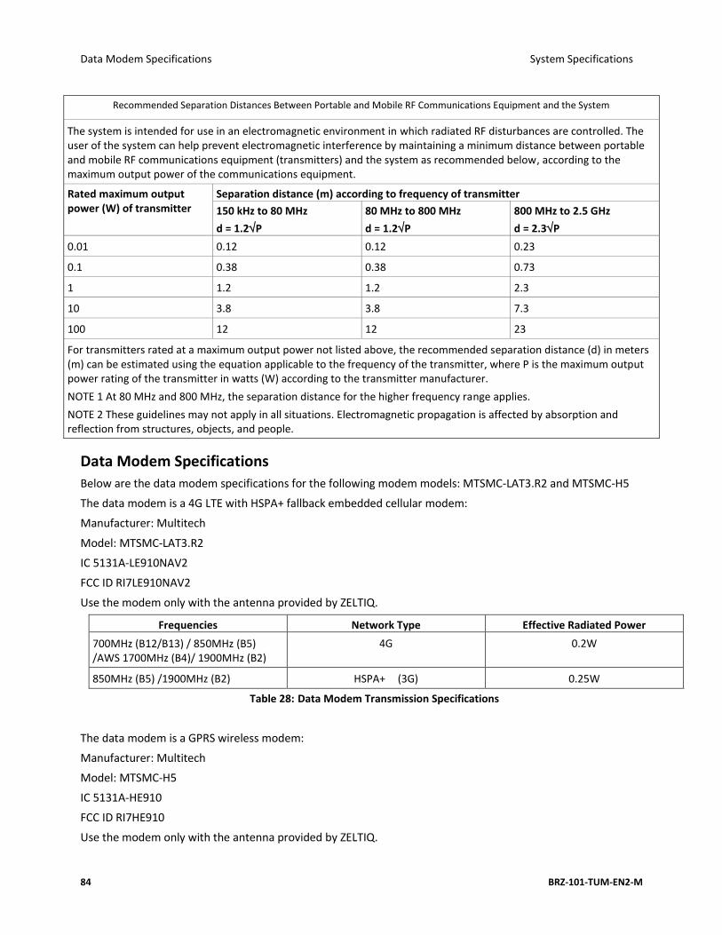
Data Modem Specifications System Specifications
84 BRZ-101-TUM-EN2-M
Recommended Separation Distances Between Portable and Mobile RF Communications Equipment and the System
The system is intended for use in an electromagnetic environment in which radiated RF disturbances are controlled. The user of the system can help prevent electromagnetic interference by maintaining a minimum distance between portable and mobile RF communications equipment (transmitters) and the system as recommended below, according to the maximum output power of the communications equipment.
Rated maximum output power (W) of transmitter
Separation distance (m) according to frequency of transmitter
150 kHz to 80 MHz
d = 1.2P
80 MHz to 800 MHz
d = 1.2P
800 MHz to 2.5 GHz
d = 2.3P
0.01 0.12 0.12 0.23
0.1 0.38 0.38 0.73
1 1.2 1.2 2.3
10 3.8 3.8 7.3
100 12 12 23
For transmitters rated at a maximum output power not listed above, the recommended separation distance (d) in meters (m) can be estimated using the equation applicable to the frequency of the transmitter, where P is the maximum output power rating of the transmitter in watts (W) according to the transmitter manufacturer.
NOTE 1 At 80 MHz and 800 MHz, the separation distance for the higher frequency range applies.
NOTE 2 These guidelines may not apply in all situations. Electromagnetic propagation is affected by absorption and reflection from structures, objects, and people.
Data Modem Specifications
Below are the data modem specifications for the following modem models: MTSMC-LAT3.R2 and MTSMC-H5
The data modem is a 4G LTE with HSPA+ fallback embedded cellular modem:
Manufacturer: Multitech
Model: MTSMC-LAT3.R2
IC 5131A-LE910NAV2
FCC ID RI7LE910NAV2
Use the modem only with the antenna provided by ZELTIQ.
Frequencies Network Type Effective Radiated Power
700MHz (B12/B13) / 850MHz (B5) /AWS 1700MHz (B4)/ 1900MHz (B2)
4G 0.2W
850MHz (B5) /1900MHz (B2) HSPA+ (3G) 0.25W
Table 28: Data Modem Transmission Specifications
The data modem is a GPRS wireless modem:
Manufacturer: Multitech
Model: MTSMC-H5
IC 5131A-HE910
FCC ID RI7HE910
Use the modem only with the antenna provided by ZELTIQ.
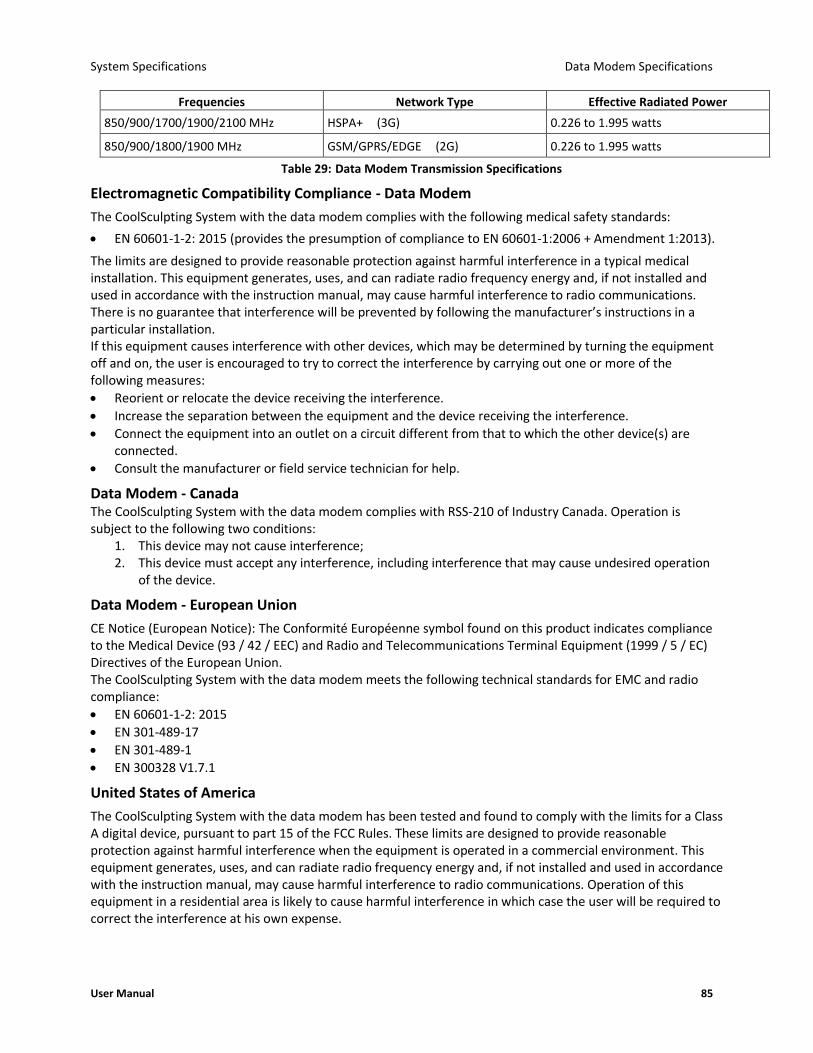
System Specifications Data Modem Specifications
User Manual 85
Frequencies Network Type Effective Radiated Power
850/900/1700/1900/2100 MHz HSPA+ (3G) 0.226 to 1.995 watts
850/900/1800/1900 MHz GSM/GPRS/EDGE (2G) 0.226 to 1.995 watts
Table 29: Data Modem Transmission Specifications
Electromagnetic Compatibility Compliance - Data Modem
The CoolSculpting System with the data modem complies with the following medical safety standards:
• EN 60601-1-2: 2015 (provides the presumption of compliance to EN 60601-1:2006 + Amendment 1:2013).
The limits are designed to provide reasonable protection against harmful interference in a typical medical installation. This equipment generates, uses, and can radiate radio frequency energy and, if not installed and used in accordance with the instruction manual, may cause harmful interference to radio communications. There is no guarantee that interference will be prevented by following the manufacturer’s instructions in a particular installation. If this equipment causes interference with other devices, which may be determined by turning the equipment off and on, the user is encouraged to try to correct the interference by carrying out one or more of the following measures:
• Reorient or relocate the device receiving the interference.
• Increase the separation between the equipment and the device receiving the interference.
• Connect the equipment into an outlet on a circuit different from that to which the other device(s) are connected.
• Consult the manufacturer or field service technician for help.
Data Modem - Canada The CoolSculpting System with the data modem complies with RSS-210 of Industry Canada. Operation is subject to the following two conditions:
1. This device may not cause interference; 2. This device must accept any interference, including interference that may cause undesired operation
of the device.
Data Modem - European Union
CE Notice (European Notice): The Conformité Européenne symbol found on this product indicates compliance to the Medical Device (93 / 42 / EEC) and Radio and Telecommunications Terminal Equipment (1999 / 5 / EC) Directives of the European Union. The CoolSculpting System with the data modem meets the following technical standards for EMC and radio compliance:
• EN 60601-1-2: 2015
• EN 301-489-17
• EN 301-489-1
• EN 300328 V1.7.1
United States of America
The CoolSculpting System with the data modem has been tested and found to comply with the limits for a Class A digital device, pursuant to part 15 of the FCC Rules. These limits are designed to provide reasonable protection against harmful interference when the equipment is operated in a commercial environment. This equipment generates, uses, and can radiate radio frequency energy and, if not installed and used in accordance with the instruction manual, may cause harmful interference to radio communications. Operation of this equipment in a residential area is likely to cause harmful interference in which case the user will be required to correct the interference at his own expense.

ZELTIQ Aesthetics, Inc. 4410 Rosewood Drive Pleasanton, CA 94588 USA (925) 474-2500 www.coolsculpting.com
10/2019