USER MANUAL Compressed Air Source Connection
12
USER MANUAL Compressed Air Source Connection 06-05-18 Rev 1.2 Culturing Cells in a Mechanically Active Environment ™ Flexcell International Corporation 2730 Tucker Street, Suite 200 Burlington, NC 27215 800-728-3714 (919) 732-1591 FAX: (919) 732-5196 www.flexcellint.com COPYRIGHT © 2009 FLEXCELL INTERNATIONAL CORPORATION
Transcript of USER MANUAL Compressed Air Source Connection
USER MANUAL
Compressed Air
Source Connection
06-05-18
Rev 1.2
Culturing Cells in a Mechanically Active Environment™ Flexcell International Corporation 2730 Tucker Street, Suite 200 Burlington, NC 27215
800-728-3714 (919) 732-1591 FAX: (919) 732-5196 www.flexcellint.com
COPYRIGHT © 2009 FLEXCELL INTERNATIONAL CORPORATION
FLEXCELL® INTERNATIONAL CORPORATION
i
TABLE OF CONTENTS
Introduction ............................................................................................................ 1
Compressed Air Source Requirements for the FX-6000TM Tension System ......................... 1
Equibiaxial Strain.................................................................................................................... 1
Unconstrained Distension ....................................................................................................... 1
Uniaxial Strain ........................................................................................................................ 1
In-House Compressed Air Systems ........................................................................................ 2
Connecting In-House Compressed Air Systems to the FX-6000TM Tension
System ...................................................................................................................... 3
General Information ................................................................................................................ 3
Compressed Air Regulator Setup............................................................................................ 3
Setting up the California Air Tools Compressor ................................................ 6
Physical Specifications ......................................................................................... 10
FLEXCELL® INTERNATIONAL CORPORATION
1
INTRODUCTION
COMPRESSED AIR SOURCE
REQUIREMENTS FOR THE FX-6000™
TENSION SYSTEM
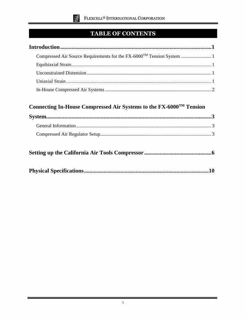
Optimizing performance on the FX-6000™
Tension System requires a compressed air
source able to maintain a free air flowrate of
5.7 cfm (161 L/min) at 100 kPa (14.5 psi).
The system can be used with the following
configurations:
• Equibiaxial strain (with cylindrical
Loading Stations™),
• Unconstrained distension (without
Loading Stations™),
• Uniaxial strain (with Arctangle®
Loading Stations™).
EQUIBIAXIAL STRAIN
The equibiaxial strain configuration uses a
BioFlex® plate with 6 cylindrical loading
posts situated in a Loading Station™ such that
the membrane translates across the lubricated
planar surface of the loading posts.
Distension of the membrane in this way
results in equibiaxial strain to the area of the
membrane over a loading post. The vacuum
requirement to produce a maximum strain of
23% on the BioFlex® membrane in this
configuration is -90 kPa. To operate the FX-
6000™ Tension System in this configuration,
a compressor is required that will provide the
following minimum specifications:
Maximum Pressure: +90 kPa (13.1 psi)
Minimum Free Airflow Rate: 5.7 cfm (161
L/min)
UNCONSTRAINED DISTENSION
The unconstrained distension configuration
uses the BioFlex® plate without loading posts
in Loading Stations™ such that the BioFlex®
membrane deforms freely downward.
Distension of the membrane in this way
results in a non-uniform strain profile on the
membrane that is maximal at the periphery
and minimal at the center. The vacuum
requirement to produce a maximum strain of
34% on the BioFlex® membrane in this
configuration is only -30 kPa. To operate the
FX-6000™ Tension System in this
configuration, a compressor is required that
will provide the following minimum
specifications:
Maximum Pressure: +30 kPa (4.4 psi)
Minimum Free Airflow Rate: 1.3 cfm (37
L/min)
UNIAXIAL STRAIN
The uniaxial strain configuration uses the
UniFlex® plate, the linear Tissue Train® plate
or the trapezoidal Tissue Train® plate with
the Arctangle® Loading Stations™ such that
the membrane deforms over the top, planar
surface of the loading posts in Loading
Station™ only at the east and west poles.
Distension of the membrane in this way
results in uniaxial strain to the area of the
membrane over the ArctangleTM loading
posts in a Loading Station™. The vacuum
requirement to produce a maximum strain of
12% on the UniFlex® membrane in this
configuration is -90 kPa. The vacuum
requirement to produce a maximum strain of
20% on the either Tissue Train® membrane in
this configuration is -90 kPa. To operate the
FX-6000™ Tension System in this
configuration, a compressor is required that
will provide the following minimum
specifications:
Maximum Vacuum: +90 kPa (13.1 psi)
Minimum Free Airflow Rate: 5.7 cfm (161
L/min)
FLEXCELL® INTERNATIONAL CORPORATION
2
IN-HOUSE COMPRESSED AIR SYSTEMS
If an in-house compressed air system is being
used in the laboratory, the system capabilities
must be known to determine if it is sufficient
to operate the FX-6000™ Tension System in
the desired configuration. The maximum
pressure and free airflow rate of the
compressor generated by the in-house air
compressor will likely be greater than that
required by the FX-6000™ ,and will therefore
require proper air regulation. However,
because in-house compressed air is often
shared among labs, neither the maximum
pressure level nor airflow rate available are
certain to be stable at all times.
If access of equipment to measure the
capabilities of the in-house compressed air
system is unavailable, the FX-6000™ can be
safely tested by connecting it to a pressure-
regulated outlet. The performance of the unit
can be noted with respect to the house
compressor to determine if it will be effective
enough for experimental purposes. The
maximum pressure of the in-house
compressor can be tested by programming a
regimen with the following parameters: Sine
wave, 0-23% elongation, 0.25 Hz, DC% =
50, 10 cycles.
This regimen should be run with standard
FLEX IN and FLEX OUT tubing lengths and
a BioFlex® baseplate with four culture plates
in place and four 25 mm cylindrical Loading
Stations™. Adjust the compressed air outlet
regulator to approximately +90 kPa and start
the regimen. If the actual output minimum %
elongation is less than 0.50%, then the in-
house air compressor is providing enough
positive pressure to run the unit at its
maximum capability.
The airflow rate of the in-house compressor
can be tested by programming a regimen with
the following parameters: Sine wave, 0-15%
elongation, 1.0 Hz, DC% = 50, 20 cycles.
This regimen should be run with standard
FLEX IN and FLEX OUT tubing lengths and
a BioFlex® baseplate with four culture plates
in place and four 25 mm cylindrical Loading
Stations™. Adjust the compressed air outlet
regulator to approximately +90 kPa and start
the regimen. If the actual output minimum %
elongation is less than 0.50%, then the in-
house air compressor is providing enough
airflow to run the unit at its maximum
capability.
If the output minimum % elongation is higher
than 0.50%, then the in-house air compressor
is going to be a limitation in the performance
of the FX-6000™. This will only be a problem
if the combination of % elongation and
frequency that is desired for particular
experiments is unachievable. Using the FX-
6000™ with an air compressor system that
does not allow the FX-6000™ to run at its
maximum capability will not damage the
unit. The FX-6000™ will adjust to make the
best possible use of the compressed air that is
being provided.
If there are questions about the operation of
the FX-6000™ Tension System with the in-
house compressed air system, call Flexcell®
and ask to speak with a technical service
representative.
FLEXCELL® INTERNATIONAL CORPORATION
3
CONNECTING IN-HOUSE COMPRESSED AIR SYSTEMS TO THE FX-6000™ TENSION SYSTEM
GENERAL INFORMATION
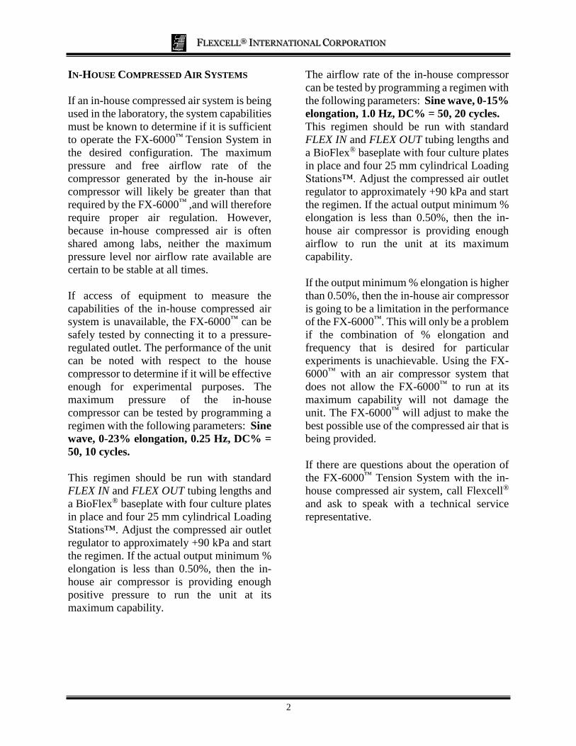
The FX-6000™ Tension System has a single
connection for the compressed air source.
This connection port is located on the back of
the FX6K™ Tension FlexLink® and is labeled
VENT as shown in Figure 1.
All of the following compressed air source
configurations will need a single source line
coming from a pressure regualtor to the
VENT port on the back of the FlexLink®. The
VENT port requires tubing dimensions of 3/8”
(9.5 mm) outer diameter by ¼” (6.4 mm)
inner diameter. Flexcell® recommends the 3/8” clear tubing that is provided with the FX-
6000™ Tension System.
Figure 1. FX-6000 FlexLink® back panel.
COMPRESSED AIR REGULATOR SETUP
If your facility has a central in-house air
compressor, speak to the building manager or
plumbing technician to drop a compressed
air-line into the location of FlexLink®
operation. The line will require a shutoff
valve within reachable distance to open or
close the line. The air-line should be securely
offset approximately 2-3” from the wall. To
install the provided pressure regulator, it is
recommended to have a union joint with a
90° elbow installed on the end of the air-line
to allow removal the piping past the shutoff
valve. The pressure regulator will connect to
a ¼” NPT threaded male fitting.
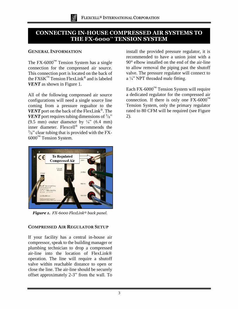
Each FX-6000™ Tension System will require
a dedicated regulator for the compressed air
connection. If there is only one FX-6000™
Tension System, only the primary regulator
rated to 80 CFM will be required (see Figure
2).
FLEXCELL® INTERNATIONAL CORPORATION
4
Figure 2. Single FX-6000 regulator setup
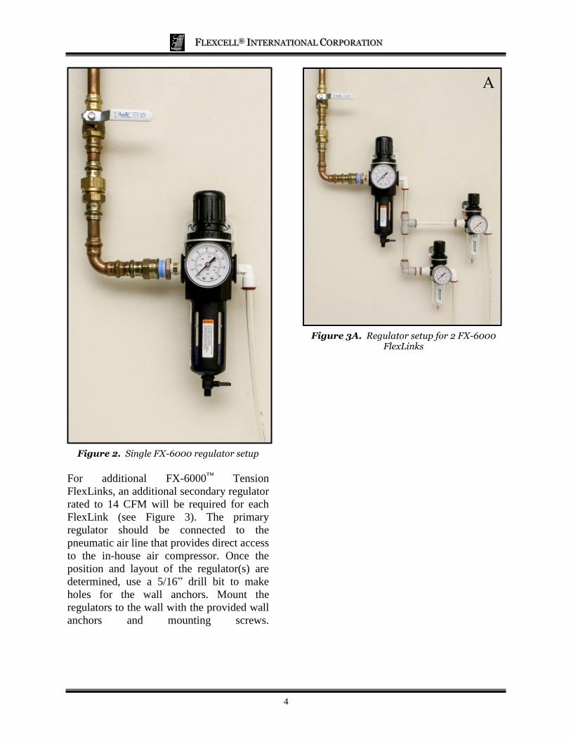
For additional FX-6000™ Tension
FlexLinks, an additional secondary regulator
rated to 14 CFM will be required for each
FlexLink (see Figure 3). The primary
regulator should be connected to the
pneumatic air line that provides direct access
to the in-house air compressor. Once the
position and layout of the regulator(s) are
determined, use a 5/16” drill bit to make
holes for the wall anchors. Mount the
regulators to the wall with the provided wall
anchors and mounting screws.
Figure 3A. Regulator setup for 2 FX-6000
FlexLinks
FLEXCELL® INTERNATIONAL CORPORATION
5
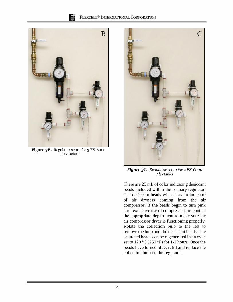
Figure 3B. Regulator setup for 3 FX-6000 FlexLinks
Figure 3C. Regulator setup for 4 FX-6000
FlexLinks
There are 25 mL of color indicating desiccant
beads included within the primary regulator.
The desiccant beads will act as an indicator
of air dryness coming from the air
compressor. If the beads begin to turn pink
after extensive use of compressed air, contact
the appropriate department to make sure the
air compressor dryer is functioning properly.
Rotate the collection bulb to the left to
remove the bulb and the desiccant beads. The
saturated beads can be regenerated in an oven
set to 120 °C (250 °F) for 1-2 hours. Once the
beads have turned blue, refill and replace the
collection bulb on the regulator.
FLEXCELL® INTERNATIONAL CORPORATION
6
SETTING UP THE CALIFORNIA AIR TOOLS COMPRESSOR
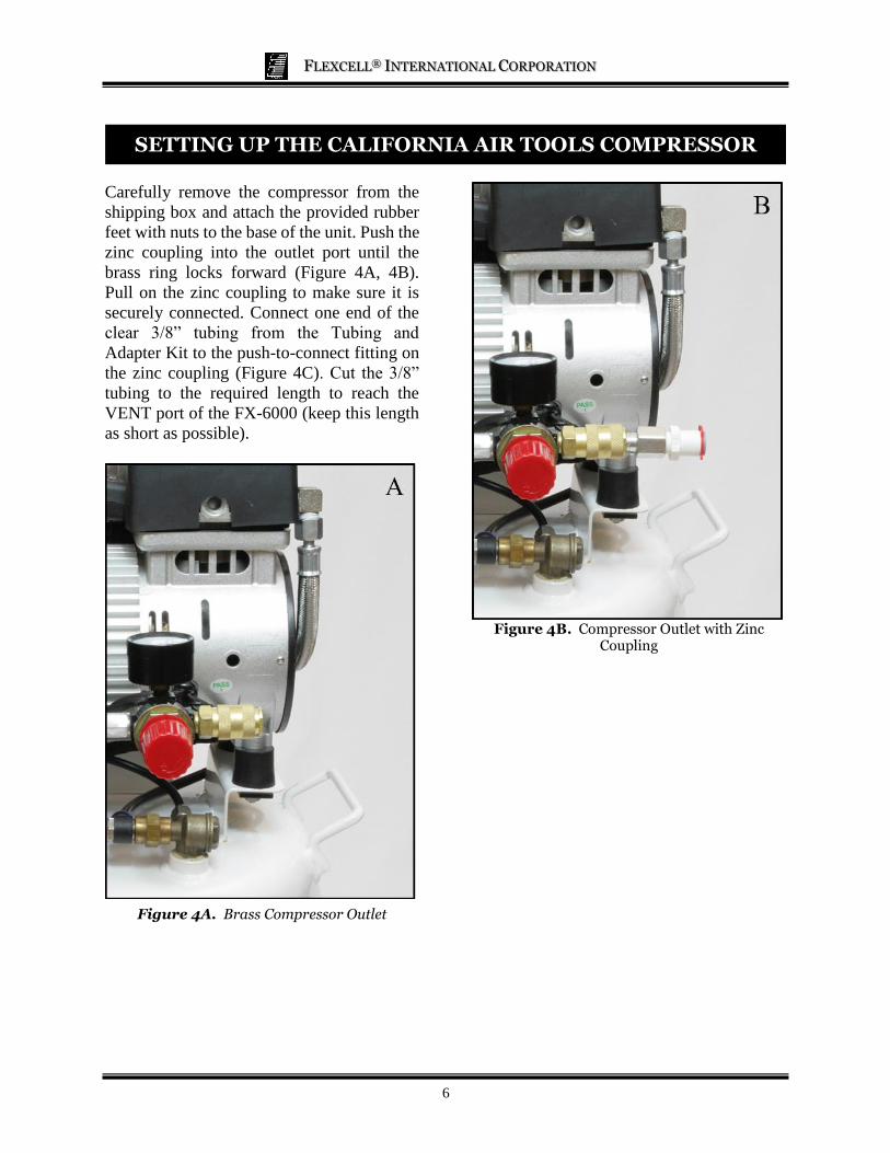
Carefully remove the compressor from the
shipping box and attach the provided rubber
feet with nuts to the base of the unit. Push the
zinc coupling into the outlet port until the
brass ring locks forward (Figure 4A, 4B).
Pull on the zinc coupling to make sure it is
securely connected. Connect one end of the
clear 3/8” tubing from the Tubing and
Adapter Kit to the push-to-connect fitting on
the zinc coupling (Figure 4C). Cut the 3/8”
tubing to the required length to reach the
VENT port of the FX-6000 (keep this length
as short as possible).
Figure 4A. Brass Compressor Outlet
Figure 4B. Compressor Outlet with Zinc Coupling
FLEXCELL® INTERNATIONAL CORPORATION
7
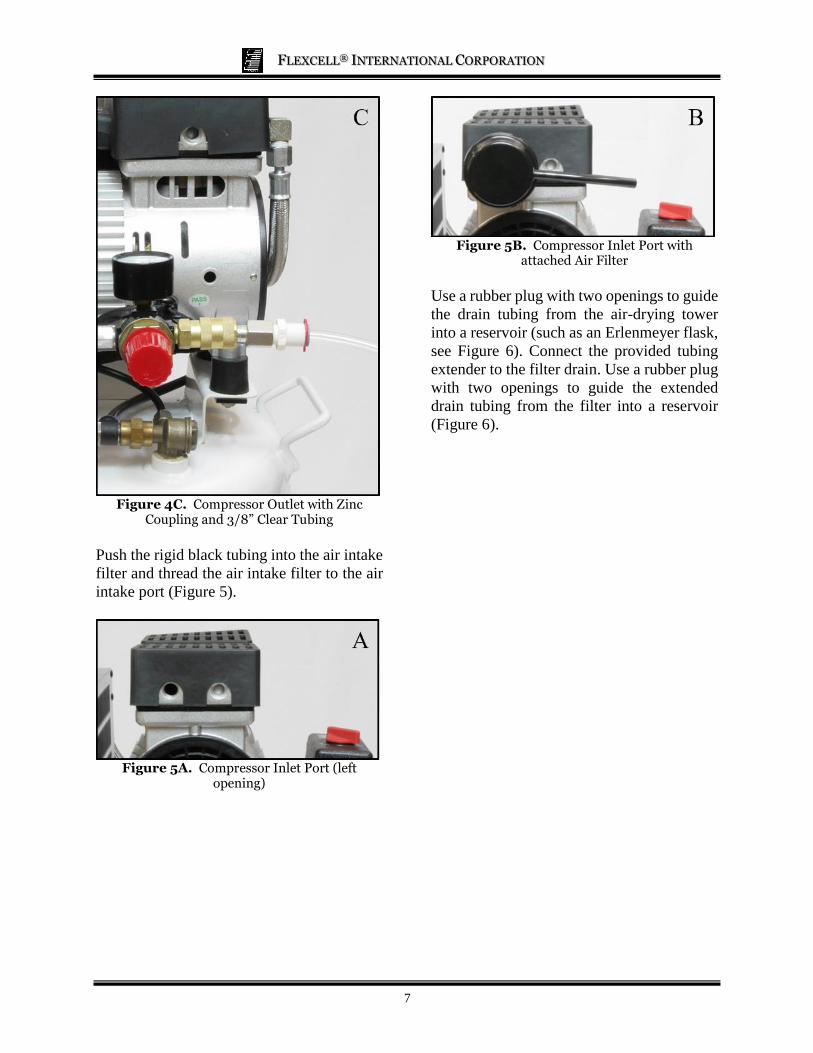
Figure 4C. Compressor Outlet with Zinc Coupling and 3/8” Clear Tubing
Push the rigid black tubing into the air intake
filter and thread the air intake filter to the air
intake port (Figure 5).
Figure 5A. Compressor Inlet Port (left opening)
Figure 5B. Compressor Inlet Port with attached Air Filter
Use a rubber plug with two openings to guide
the drain tubing from the air-drying tower
into a reservoir (such as an Erlenmeyer flask,
see Figure 6). Connect the provided tubing
extender to the filter drain. Use a rubber plug
with two openings to guide the extended
drain tubing from the filter into a reservoir
(Figure 6).
FLEXCELL® INTERNATIONAL CORPORATION
8
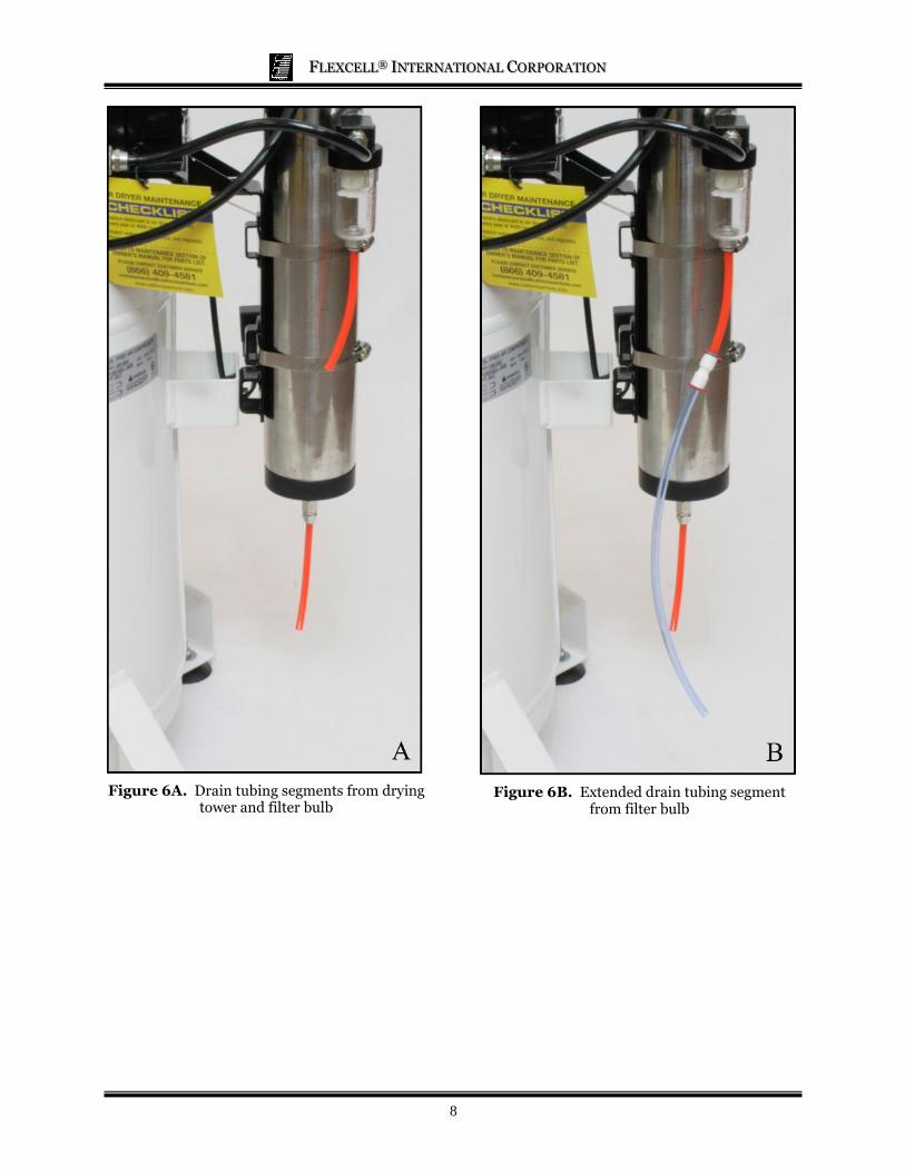
Figure 6A. Drain tubing segments from drying
tower and filter bulb
Figure 6B. Extended drain tubing segment
from filter bulb
FLEXCELL® INTERNATIONAL CORPORATION
9
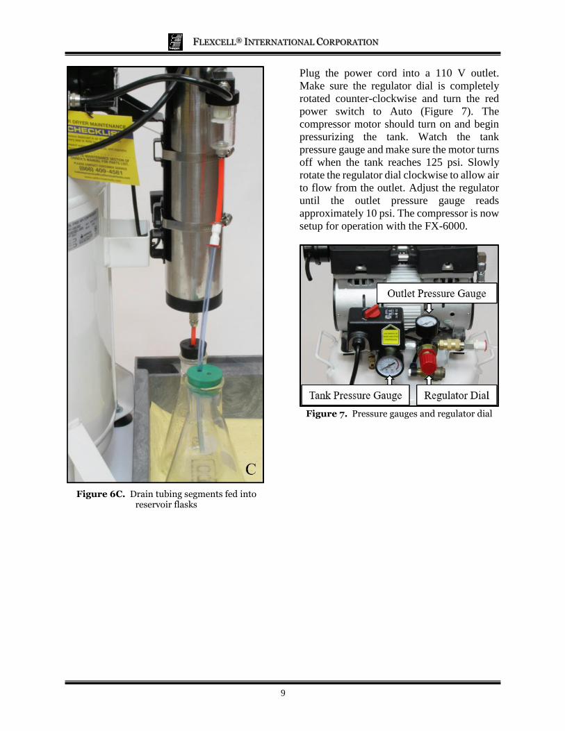
Figure 6C. Drain tubing segments fed into reservoir flasks
Plug the power cord into a 110 V outlet.
Make sure the regulator dial is completely
rotated counter-clockwise and turn the red
power switch to Auto (Figure 7). The
compressor motor should turn on and begin
pressurizing the tank. Watch the tank
pressure gauge and make sure the motor turns
off when the tank reaches 125 psi. Slowly
rotate the regulator dial clockwise to allow air
to flow from the outlet. Adjust the regulator
until the outlet pressure gauge reads
approximately 10 psi. The compressor is now
setup for operation with the FX-6000.
Figure 7. Pressure gauges and regulator dial
FLEXCELL® INTERNATIONAL CORPORATION
10
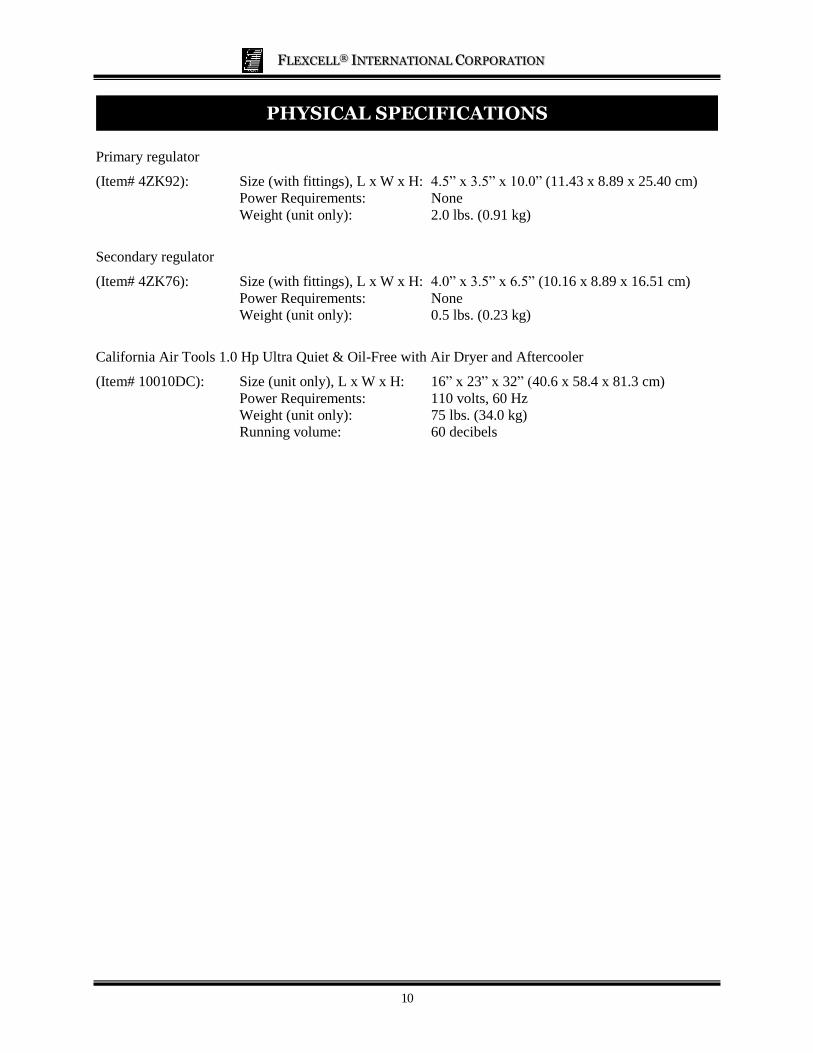
PHYSICAL SPECIFICATIONS
Primary regulator
(Item# 4ZK92): Size (with fittings), L x W x H: 4.5” x 3.5” x 10.0” (11.43 x 8.89 x 25.40 cm) Power Requirements: None
Weight (unit only): 2.0 lbs. (0.91 kg)
Secondary regulator
(Item# 4ZK76): Size (with fittings), L x W x H: 4.0” x 3.5” x 6.5” (10.16 x 8.89 x 16.51 cm)
Power Requirements: None
Weight (unit only): 0.5 lbs. (0.23 kg)
California Air Tools 1.0 Hp Ultra Quiet & Oil-Free with Air Dryer and Aftercooler
(Item# 10010DC): Size (unit only), L x W x H: 16” x 23” x 32” (40.6 x 58.4 x 81.3 cm)
Power Requirements: 110 volts, 60 Hz
Weight (unit only): 75 lbs. (34.0 kg)
Running volume: 60 decibels