USER MANUAL - comegmedical.com · AFTER SALE SERVICE ... For the address of the manufacturer please...
20
USER MANUAL
-
Upload
truongxuyen -
Category
Documents
-
view
213 -
download
0
Transcript of USER MANUAL - comegmedical.com · AFTER SALE SERVICE ... For the address of the manufacturer please...

USER MANUAL
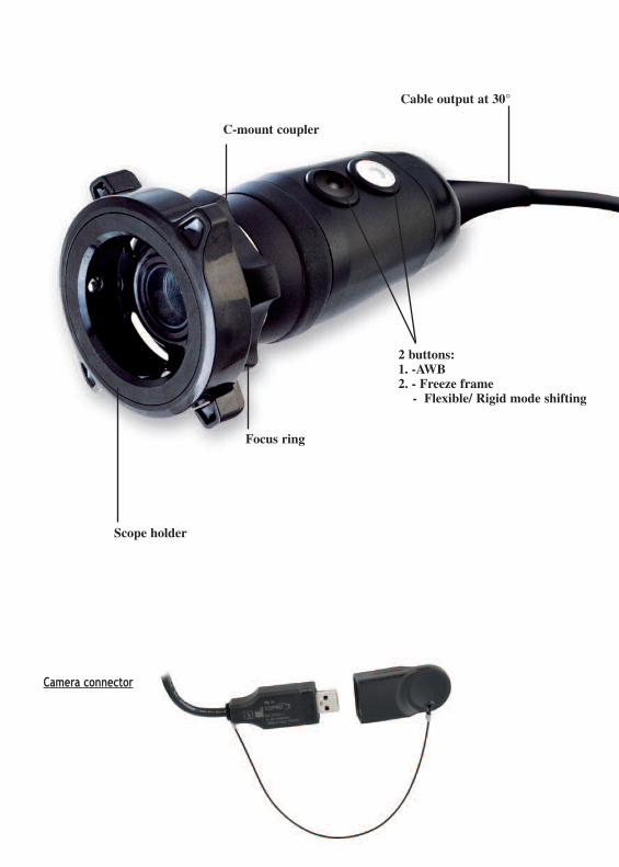
Scope holder
Focus ring
2 buttons:1. -AWB2. - Freeze frame
- Flexible/ Rigid mode shifting
C-mount coupler
Cable output at 30°
Camera connector

0 1 1 2 9 3 G - 0 3 / 2 0 1 4 1
E N G L I S H
CONTENTS
INTRODUCTION . . . . . . . . . . . . . . . . . . . . . . . . . . . . . . . . . . . . . . . .3
PRESENTATION OF THE CAMERA . . . . . . . . . . . . . . . . . . . . . . . . . . . . . .3
PRECAUTION FOR USE . . . . . . . . . . . . . . . . . . . . . . . . . . . . . . . . . . . .4
REGULATORY RECOMMENDATION . . . . . . . . . . . . . . . . . . . . . . . . . . . . .54.1 CONFORMITY4.2 ELECTROMAGNETIC INTERFERENCES AND ELECTROSTATIC DISCHARGES4.3 MATERIO VIGILANCE4.4 END OF LIFE
INSTALLATION . . . . . . . . . . . . . . . . . . . . . . . . . . . . . . . . . . . . . . . . . .75.1 INSTALLATION OF THE CAMERA ON THE COMPUTER - MINIMUM CONFIGURATION5.2 INSTALLATION OF THE IMAGINE SOFTWARE AND OF THE DRIVERS 5.3 OPTIMIZING THE IMAGE
USER ADJUSTMENTS . . . . . . . . . . . . . . . . . . . . . . . . . . . . . . . . . . . . . .86.1 WHITE BALANCE6.2 THE ICE FUNCTION6.3 IMAGE CAPTURE6.4 FLEXIBLE/RIGID
RECOMMENDED PROCEDURE FOR DECONTAMINATION . . . . . . . . . . . . . . .11
AFTER SALE SERVICE . . . . . . . . . . . . . . . . . . . . . . . . . . . . . . . . . . . .12
TECHNICAL SPECIFICATIONS . . . . . . . . . . . . . . . . . . . . . . . . . . . . . . . .13
ELECTROMAGNETIC COMPATIBILITY . . . . . . . . . . . . . . . . . . . . . . . . . . .14
1
2
3
4
5
6
7
8
9
10


0 1 1 2 9 3 G - 0 3 / 2 0 1 4 3
E N G L I S H1
INTRODUCTIONThank you for your confidence shown in us by your purchase of this device.
To take full advantage and comply with all necessary precautions, you should carefully read this manual and be
well acquainted with its contents.
Sentences containing the symbol are points requiring special attention.
Sentences containing the symbol are for information.
To facilitate the installation and the use of the camera we wanted to make his handbook easier to use. Thus,
references in the page of presentation in the back of the cover (in the form of [D1] for example) are proposed
for you to visualize easily the parts of the product concerned.
PRESENTATION OF THE CAMERAIt is a waterproof, USB2 colour micro camera with detachable sensor, designed for consulting offices diagnosisdirectly from your PC computer.Its lightness, its auto-shutter, its performances in terms of sensitivity, resolutionas well as its fidelity in the respect of colours make of it the ideal diagnosis tool.
It includes:
• A 1/4” CCD, C-Mount camera head, at the end of a 3m cable.• A USB2 cable with its waterproofness cap.• A CD including: - The patient management software
- A User Manual.- A USB2 driver.
In option:• A 12 or 17mm waterproof objective and its endoscope holder ring.• A 5m USB2 extension cord.
This equipment was delivered in a cardboard box. You must keep this element for further transport of the
camera.
2

4 0 1 1 2 9 3 G - 0 3 / 2 0 1 4
E N G L I S H3
PRECAUTION FOR USE
Read the user manual.
p Respect the use and storage conditions.
p Install the camera in a clean, dry and well ventilated place.
p The installation of the camera must be exclusively done by a competent technician trained by the
manufacturer.
p To avoid risk of electrical shocks, fire, short-circuits or dangerous emanations, do not insert any metallic object
in the apparatus.
p Do not expose the camera to water and do not store it in damp places without the waterproof cap on the USB
connector (risk of electric shock).
p Use only the accessories supplied with the apparatus or proposed as option by the manufacturer.
p Do not use this camera near any flammable anaesthetics.
p This camera must not be used in a ionizing environment.
p This camera is not a sterile device.

0 1 1 2 9 3 G - 0 3 / 2 0 1 4 5
E N G L I S H4
REGULATORY RECOMMENDATION
4.1 CONFORMITY
This device has been designed and manufactured by a company with a certified quality system.
It complies with the requirements of the European Directive 93/42/EEC related to medical devices.
As a result, it complies in particular with the ad hoc electric safety (IEC) and Electromagnetic Compatibility
(EMC) standards.
4.2 ELECTROMAGNETIC INTERFERENCE AND ELECTROSTATIC DISCHARGES
Although this product complies with the EMC standards, it is possible under very special circumstances that it
may interfere with other devices or be interfered by other devices or by an unfavourable electromagnetic
environment.
To prevent such situations, it is recommended :
• To take care of the quality of the electric network (and particularly the grounding system of all the devices and
carriages) ;
• To keep the device away from Electromagnetic sources (e.g., compressor, motor, transformer, HF generator, etc.).
4.3 MATERIO VIGILANCE
As for any medical system, this device is subject to the provisions pertaining to materio vigilance; any serious
malfunction must be promptly communicated to the competent authorities and the manufacturer with the
greatest possible precision.
For the address of the manufacturer please see the last page of manual.
Caution: US Federal law restricts this device to sale by or on the order of a Physician
This camera is intended to be used by qualified physicians in general and plastic surgery to provide access,
illumination and allow observation or manipulation of body cavities, hollow organs, and canals.
4.4 END OF LIFE
This appliance is marked according to the European Directive 2002/96/EEC on Waste Electrical and Electronic
Equipment (WEEE).
By ensuring this product is disposed of properly, you will help prevent potential negative consequences for the
environment and human health, which could otherwise be caused by inappropriate waste handling of this
product.
The symbol on the product, or on the documents accompanying the product, indicates that this appliance
may not be treated as household waste. Instead it shall be handed over to the applicable collection point for
recycling of electrical and electronic equipment.
Disposal must be carried out in accordance with local environmental regulations for waste disposal.
For more detailed information about treatment, recovery and recycling of this product, please contact the local
dealer to whom you purchased the product from and who will tell you how to proceed.

6 0 1 1 2 9 3 G - 0 3 / 2 0 1 4
E N G L I S H5
INSTALLATION
5.1 INSTALLATION OF THE CAMERA ON THE COMPUTER
A minimum configuration of the computer is necessary.
A USB2 driver included on the CD-ROM is necessary to the functionning of the camera.
DO NOT PLUG THE CAMERA ON A USB PORT ON THE FRONT PANEL OF THE COMPUTER.
INSTALL THE SOFTWARE BEFORE PLUGGING THE CAMERA.
5.2 INSTALLATION OF THE IMAGING SOFTWARE AND OF THE DRIVERS
Refer to the software installation manual located in the document directory of the Imaging software CD-ROM.
Recommended System Requirements
Intel® core i5 processor2 Gb of RAM320 Gb of hard disk space4 USB 2.0 Hi-Speed portsOperating system: Windows® 7 Pro sP1Graphics Card with NVIDIA or ATI chipset /512 MB of unshared video RAM with support forDirectX 9 USB chipset: Intel ou NEC® / Renesas®
Screen Resolution: 1280x 1024 or higher
Minimum System Requirements
Intel® Pentium iv – 1,3 ghz processor512 Mb of RAM250 Gb of hard disk space2 USB 2.0 Hi-Speed portsOperating system: Windows® xP Pro sP3Graphics Card: 32 MB of unshared video RAMwithsupport for DirectX 9
USB chipset: Intel ou NEC® / Renesas®
Screen Resolution: 1024 x 768
0 1 1 2 9 3 G - 0 3 / 2 0 1 4 7
E N G L I S H
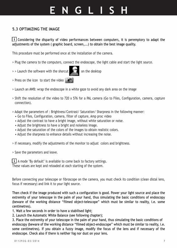
5.3 OPTIMIZING THE IMAGE
Considering the disparity of video performances between computers, it is peremptory to adapt theadjustments of the system ( graphic board, screen,...) to obtain the best image quality.
This procedure must be performed once at the installation of the camera.
> Plug the camera to the computers, connect the endoscope, the light cable and start the light source.
> > Launch the software with the shorcut on the desktop
> Press on the icon to start the video
> Launch an AWB: wrap the endoscope in a white gaze to avoid any dark area on the image
> Shift the resolution of the video to 720 x 576 for a PAL camera (Go to Files, Configuration, camera, captureconnection).
> Adapt the parameters of : Brightness/Contrast/ Saturation/ Sharpness in the following manner:• Go to Files, Configuration, camera, filter of capture, Amp proc video• Adjust the contrast to have a bright image, without white saturation or noise.• Adjust the brightness to have a bright and noiseless image.• Adjust the saturation of the colors of the images to obtain realistic colors.• Adjust the sharpness to enhance details without increasing the noise.
> If necessary, modify the adjustments of the monitor to adjust colors and brightness.
> Save the parameters and leave.
A mode "By default" is available to come back to factory settings.These values are kept and reloaded at each starting of the system.
Before connecting your telescope or fibroscope on the camera, you must check its condition (clean distal lens,focus if necessary) and link it to your light source.
Then check if the image produced with such a configuration is good. Power your light source and place theextremity of your telescope in the palm of your hand, thus simulating the basic conditions of endoscopy(beware of the working distance “filmed object-telescope” which must be similar to reality, i.e. somecentimetres). 1. Wait a few seconds in order to have a stabilised light;2. Launch the Automatic White Balance (see following chapter);3. Place the extremity of your telescope in the palm of your hand, thus simulating the basic conditions ofendoscopy (beware of the working distance “filmed object-endoscope” which must be similar to reality, i.e.some centimetres). If you obtain a fuzzy image, modify the focus of the lens and if necessary of theendoscope. Check also if there is neither fog nor dust on your lens.
8 0 1 1 2 9 3 G - 0 3 / 2 0 1 4
E N G L I S H
USER ADJUSTMENTS
6.2 WHITE BALANCE
Prior to performing an AWB, the camera must be plugged to the computer with the endoscope and the light
source connected. If there is not enought light, the AWB will not be done.
• Film a white surface, a white gaze preferably and take care it is properly placed before the endoscope. (beware
the produced image is clear), see Chap. 5.3.
• Press on the button of the white balance of the camera (white button) or of the software.
• A white square appears on the screen indicating a pending white balance, do not move until this square
disappears, indicating the end of the white balance.
Each balance is memorised. Thus, the next time you turn on the camera (and if no parameters of your image
chain were modified), you will find the same colours.
You need to do a new white balance if:
• You change the type of light source;
• You change your lamp (new one);
• You change the optics;
• You change the light cable;
• You not satisfied with the reproduction of the colours.
If you are not satisfied with the quality of the colours, think to check the adjustments of your monitor
(Chroma, contrast,...)
6
0 1 1 2 9 3 G - 0 3 / 2 0 1 4 9
E N G L I S H
6.2 THE ICE FUNCTION
With the new "ICE" (Intelligent Control Endoscope) device built in this camera, the white balance youjust performed also allows to optimize all the settings whatever the endoscope used is.
For each white balance, this exclusive process analyses:
• the size of the endoscope to adapt the field of vision of the camera,
• the color temperature from the light source to determine its wavelength,
• the color temperature of the light going through the endoscope to restore realistic colors during the
white balance.
• the minimum level of light to warn the user in case of failure.
6.3 IMAGE CAPTURE
A short pressure on the black button will allow you to capture an image.
According to the parameter settings of your Imaging software, the image with remain frozen on the
screen and you will have to press again on the same button to come back to live, or the image will
automatically shift to the live mode.
In both cases, the captured image is automatically saved in the patient file.

1 0 0 1 1 2 9 3 G - 0 3 / 2 0 1 4
E N G L I S H
6.4 FLEXIBLE/RIGID
This function is used to guarantee an excellent image quality whatever the used endoscope.
FLEXIBLE: this function activates the ANTIMOIRE filter of the camera. It is used only for flexible endoscopes made
with optic fibers.
RIGID: this function cancels the ANTIMOIRE filter of the camera and allows getting back the DETAILS of the image.
It is used for rigid and semi-rigid endoscopes.
A long pressure on the capture button (black) will active the anti-moiré*. A new long pressure will shift
back to Rigid.
When the anti-moiré* mode is activated, an F appears on the low right side of your screen.
*Anti-moiré : correction of the natural default of aliasing due to the association of a CCD camera with an
endoscope with optic fibres.
Moiré Anti-moiré

0 1 1 2 9 3 G - 0 3 / 2 0 1 4 1 1
E N G L I S H7
RECOMMENDED PROCEDURE FOR DECONTAMINATIONCAUTION: This procedure is only to be used if the cap of the USB connector is correctly closed.
The camera sensor and the lens are designed for a cold decontamination by immersion (Steranios, Chlore
Dioxyde, Hexanios, Tristel swipes)....). All other methods of decontamination are prohibited. The damages
due to these other methods could not be taken over by us.
Only immerse the C-Mount sensor with its objective screwed on it.
It is peremptory to respect the procedure consisting in cleaning the parts to immerse before decontamination
and after decontamination, to rinse carefully with sterile water all the parts which have been in contact with
the decontaminant.
CAUTION !
• It is peremptory to rinse abundantly the parts which have been in contact with the decontaminant.
• Use unwoven compresses for the drying of the distal lens so not to scratch it.
• The procedures described are advisory, they can, in no cases, be substituted to official recommandations
or directives.
• The decontamination being linked to the products, methods and/or selected tools, remains entirely under
the total responsability of the people concerned.

E N G L I S H
1 2 0 1 1 2 9 3 G - 0 3 / 2 0 1 4
E N G L I S H
AFTER SALE SERVICENo special maintenance is necessary on the camera. Here is a list of common problems which are easy to troubleshoot.For all other cases, contact our Maintenance Service that will help you in best delay. We remind you that themishandlings are not guaranteed.
8.1 NO IMAGE ON SCREEN
• Check if the camera is correctly connected and if the imaging software is opened and correctly installed (See Chap. 5).
8.2. FLICKERING IMAGE
• Check the minimal configuration of the computer in Chap.5.• Keep only the imaging software active, close any other software.• Do not plug the camera on the front panel of the computer.
8.3. THE IMAGE IS FUZZY UNIFORMELY WHITE
• Check if there is no blur on the lens.• Check if the sensor does not aim at a too lighted object.• Check the focus of the lens.
8.4. THE IMAGE IS TOO CLEAR OR TOO DARK
• Check if the " BRIGHTNESS" and "CONTRAST" parameters are well adjusted (See Chap.5).
If the problem remains and if you are led to send us back the camera, be careful to do it in its original packing.Likewise, you must send us the whole system (sensor, lenses, and cords). Be kind enough to join an explanatorynote relative to the observed default to the expedition bill.At the reception of your equipment, you will have to check its state and to enter a reservation on the deliverybill if necessary. You will then have 48 hours to confirm them by recommended letter addressed to the carrier.Beyond this delay, the carrier may deny these reservations. In the case where equipment shipped by us suffersdamages during the travel, the amount of the repairing will be charged whether to the carrier if the reservationwere entered in the delays, or to the consignee in the contrary.Think to check rapidly the good functioning of the equipment which has just travelled.Any other interventions being performed by our After Sales Service, no Service Manuals will be supplied.
8
0 1 1 2 9 3 G - 0 3 / 2 0 1 4 1 3
9
TECHNICAL SPECIFICATIONS• BF Type camera• Sensor: CCD 1/4” high sensitivity• Resolution of the sensor: (752 x 582) PAL ; (768 x 494) NTSC• Definition: 470 lines• Sensitivity : 2 lux• Signal/Noise Ratio : 52 dB• Electronic shutter: Automatic (1/50 to 1/100 000)• Variable surface of analyse of the shutter• White Balance: Automatic• Video enhancement "SHARPNESS"; electronic anti-moire filter for flexible fibrescope• Modification of the video parameters• Automatic detection of the colour temperature according to the used light source• Automatic saving of the adjustments parameters• 2 programmable buttons• Cable length: 3 meters, Ø = 5 mm• 1 USB 2.0 output• Power supply: 5 V DC• Power consumption : 2.5 VA• Operating temperature range: +10°C / +35°C• Operating relative humidity range: 30 to 75 %• Transport and storage temperature range: -10°C / +45°C• Transport and storage relative humidity range: 20% to 85%• Operating, transport and storage atmospheric pressure range: 700hPa to 1060hPa• Continuous Service• Not adapted to a use close to a mixture of inflammable anaesthetic with air or oxygen or nitrous oxide.• Comply with the European Directive 93/42/EEC, IEC 60601-2-18 and Amendment for CANADA and USA.
FEATURES OF THE CAMERA HEAD:• ABS waterproof camera head• Front part of the C-Mount made of aluminium• Size of the sensor: L = 87mm; Ø = 30 mm• Weight of the sensor: 210 g
ACCESSORIES• Objective F=12 or 17mm with endoscope holder• Weight of the objective : 60g
1 CD-ROM including:• The pilot of the camera• The patient management imaging software • Software tools.

1 4 0 1 1 2 9 3 G - 0 3 / 2 0 1 4
E N G L I S H10
ELECTROMAGNETIC COMPATIBILITY
10.1 GUIDE AND DECLARATION BY MANUFACTURER – ELECTROMAGNETIC EMISSIONS
This camera is designed to be used within the electromagnetic environment specified below. The user should
ensure that it is indeed used within this environment.
Emissions test Compliance Electromagnetic environment - Guide
RF emissionsCISPR 11
Group 1This camera only uses radioelectrical energy for its internalsubsystems. Therefore, it emits very low RF energy and is notlikely to interfere with nearby electronic devices.
RF emissionsCISPR 11
Class B This camera can be used in all domestic premises, includedpremises directly connected to the public low-voltage powerdistribution network used for powering buildings for residentialuse. This camera can be used in all premises other than residentialpremises and premises connected directly to the public low-voltage power distribution network used for powering residentialbuildings.
Harmonic emissionsEN 61000-3-2
Conform
Voltage fluctuations / flickerEN 61000-3-3
Conform

0 1 1 2 9 3 G - 0 3 / 2 0 1 4 1 5
E N G L I S H
10.2 GUIDE AND DECLARATION BY THE MANUFACTURER – ELECTROMAGNETIC IMMUNITY
This camera is designed to be used within the electromagnetic environment specified below. The user shouldensure that it is indeed used within this environment.
Immunity testCEI 60601
severity levelCompliance
levelElectromagnetic environment - Guide
Electrostatic dischargesEN 61000-4-2
± 6 kV via contact± 8 kV via air
± 6 kV ± 8 kV
The floor should be in timber, concrete or tiling. If the floor is covered
with a synthetic material, the relative humidity should be at least 30%.
Quick transients in burstsEN 61000-4-4
± 2 kV for power lines± 1 kV for
input/output lines
± 2 kV± 1 kV
Voltage shocksEN 61000-4-5
Differential mode ± 1 kVCommon mode ± 2 kV
± 1 kV± 2 kV
Brown-outs, brief powerfailures and voltage variationsEN 61000-4-11
<5% UT – for 10 ms40% UT – for 100 ms70% UT – for 500 ms
<5% UT – for 5 s
<5% UT 10 ms<40% UT 100 ms<70% UT 500 ms
<5% UT 5 s
Magnetic field at network frequency(50/60 Hz)
3 A/m 3 A/m
Conducted RFEN 61000-4-6
Radiated RFEN 61000-4-3
3 Vrms150 kHz to 80 MHz
3 V/m80 MHz to 2.5 GHz
3V
3V/m
The quality of the main power supply should be that of a typical
commercial or hospital environment.
The quality of the main power supply should be that of a typical
commercial or hospital environment.
The magnetic field at the network frequency should be at a level
characteristic of a location within a typical commercial or hospital
environment.
Portable and mobile RF communication devices must not be usedat a distance from this camera – including cables – that is less thanthe recommended separation distance calculated using applicableformulae according to the transmitter’s frequency.
Recommended separation distance
d = 1,16 P
d = 1,16 P 80 MHz à 800 MHz
d = 2,33 P 800 MHz à 2,5 GHz
In which P is the maximum output power of the transmitter, inWatts (W), assigned by the manufacturer of the transmitter andthe recommended separation distance (d) in meters (m).The field levels emitted by immobile RF transmitters – which areto be established by an electromagnetic measurement at the site –must be lower than the compliance level in each frequency band.Interference can occur nearby devices bearing the followingsymbol:
Note : UT is the nominal value of the power voltage applied during the test.Note 1 : At 80 MHz and 800 MHz, the higher frequency band applies.Note 2 : These recommendations may not apply in all situations. The propagation of electromagnetic waves is modified by absorption andreflection due to structures, objects and people.
a The field level of immobile transmitters, such as radio telephone base stations (cellular and cordless) and mobile terrestrial radio systems, amateur radio systems,AM/FM radio communication systems, and TV systems cannot be evaluated theoretically with precision. To ascertain the electromagnetic environment due toimmobile RF transmitters, a site measurement must be performed. If a field level measured within the environment in which this camera is used exceeds the aboveapplicable compliance levels, check that this camera operates in a satisfactory manner. If abnormal operation is observed, additional measurements should betaken, such as reorientation or relocation of the reference system.
b Outside the frequency band of 150 kHz to 80 MHz, the field level should be less than 3 V/m
The quality of the main power supply should be that of a typicalcommercial or hospital environment.If the user of this camera requires to be able to continue to workduring interruptions in the main power supply, it is recommended thatthis camera be powered via a UPS or battery.
1 6 0 1 1 2 9 3 G - 0 3 / 2 0 1 4
E N G L I S H
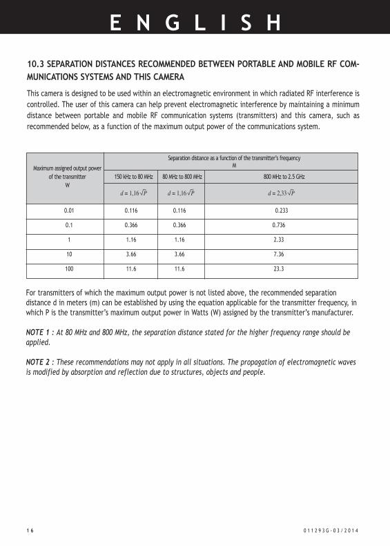
10.3 SEPARATION DISTANCES RECOMMENDED BETWEEN PORTABLE AND MOBILE RF COM-
MUNICATIONS SYSTEMS AND THIS CAMERA
This camera is designed to be used within an electromagnetic environment in which radiated RF interference is
controlled. The user of this camera can help prevent electromagnetic interference by maintaining a minimum
distance between portable and mobile RF communication systems (transmitters) and this camera, such as
recommended below, as a function of the maximum output power of the communications system.
For transmitters of which the maximum output power is not listed above, the recommended separationdistance d in meters (m) can be established by using the equation applicable for the transmitter frequency, inwhich P is the transmitter’s maximum output power in Watts (W) assigned by the transmitter’s manufacturer.
Note 1 : At 80 MHz and 800 MHz, the separation distance stated for the higher frequency range should beapplied.
Note 2 : These recommendations may not apply in all situations. The propagation of electromagnetic wavesis modified by absorption and reflection due to structures, objects and people.
Maximum assigned output power
of the transmitter
W
Separation distance as a function of the transmitter’s frequencyM
0.01 0.116 0.116 0.233
0.1 0.366 0.366 0.736
1 1.16 1.16 2.33
10 3.66 3.66 7.36
100 11.6 11.6 23.3
150 kHz to 80 MHz 80 MHz to 800 MHz 800 MHz to 2.5 GHz
d = 1,16 P d = 1,16 P d = 2,33 P

0 1 1 2 9 3 G - 0 3 / 2 0 1 4 1 7
E N G L I S H
Manufacturing date/ Date de fabrication / Fecha de fabricacion / Data di produzione /Herstellung datum
Manufacturer / Fabricant / Fabrica / Produzione / Hersteller
Comply with the European Directive 93/42/CEE / Conforme à la directive européenne93/42/42/CEE / Conforme a la directiva europea 93/42/CEE / Conforme alla direttivaeuropea 93/42/CEE / Entspricht des Europäischen Weisung 93/42/CEE
Read the User Manual / Lire le manuel d’utilisation / Observe la documentacion adjunta /Observe la documentacion adjunta / Leggere la documentazione allegata /Begleitpapiere beachten
Dispositif de type BF / Type BF device / Apparecchio mod.BF / Aparato del tipo BF /Gerät des Typs BF
UK : Disposal of electric and electronic equipment marketed after 13/August/2005.This symbol indicates that the product cannot be treated with domestic waste.FR : Equipement électronique et électrique mis sur le marché après le 13/08/2005.Ce symbole indique que ce produit ne doit pas être traité avec les déchets ménagers.ESP : Equipamiento electrónico introducido en el mercado después del 13/08/2005.Este símbolo indica que este producto no debe ser tratado junto a los residuosdomésticos.ITA : Apparecchiatura elettronica ed elettrica messa sul mercato dopo il 13/08/2005.Questo simbolo indica che questo prodotto non deve essere trattato come un rifiutodomestico.DE : Elektronische und elektrische Geräte, die nach dem 13.08.2005 auf den Marktgebracht wurden. Dieses Symbol weist darauf hin, dass dieses Produkt nicht über denHaushaltsmüll entsorgt werden darf
SYMBOLS-SYMBOLES-PICTOGRAMAS-SIMBOLI-BILDZEICHEN:

Manufac tu rer : SOPRO ZAC Athé l ia IV Avenue des Genévr ie rs 13705 La Cio ta t cedex FRANCE Tél +33(0) 442 98 01 01 - Fax +33 (0) 442 71 96 90 - E-mail : [email protected] - Web : www.sopro-comeg.com
Non
con
trac
tual
doc
umen
t –
Ref.
0112
93G
-03/
2014
– C
opyr
ight
© 2
014
SOPR
O-C
OM
EG.
All
righ
ts r
eser
ved.
No
info
rmat
ion
or p
art
of t
his
docu
men
t m
ay b
e re
prod
uced
or
tran
smit
ted
in a
ny f
orm
wit
hout
the
pri
or p
erm
issi
on o
f SO
PRO
-CO
MEG