USER MANUAL AD 131 and AD 132 pH/mV/Temperature Waterproof ... · AD 131 and AD 132...
56
AD 131 and AD 132 pH/mV/Temperature Waterproof Meters USER MANUAL www.adwainstruments.com
Transcript of USER MANUAL AD 131 and AD 132 pH/mV/Temperature Waterproof ... · AD 131 and AD 132...
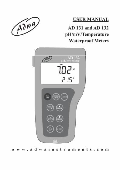
AD 131 and AD 132 pH/mV/Temperature
Waterproof Meters
USER MANUAL
w w w . a d w a i n s t r u m e n t s . c o m

2
Dear Customer,Thank you for choosing an Adwa product.Please read carefully this manual before starting operations.This instrument is in compliance with the EMC directive 2004/108/EC and its standards, and Low Voltage Directive 2006/95/EC and its standards for electrical equipments.For additional technical information, please e-mail us [email protected].
WARRANTYAdwa warrants this product to be free of defects in materialand workmanship as stated in the operating manual. If repairor adjustment is necessary and has not been the result ofabuse, misuse or improper handling within the warrantyperiod, please contact your dealer or the nearest Adwa Officefor the RGA (Return Goods Authorization) number to put onthe outside of your package. Warranted service will be madewithout charge. The meter is warranted for a period of 2 years,while probes are warranted for 6 months. The warrantyperiod commences from the original date of sale. Warranty isonly valid when the product is used under normal conditionsand in accordance with the instruction manual. The warrantyis void if the instrument is repaired or serviced by unauthorizedpersonnel, not used in accordance to the instructions, or ifnon-Adwa accessories such as buffer solutions, probes, etc.are used in conjunction with the meter. Adwa will not be heldresponsible for any accident whether directly or indirectly,caused by the use of this instrument.
3
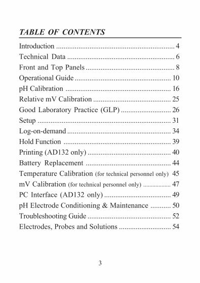
TABLE OF CONTENTS
Introduction ................................................................ 4Technical Data .......................................................... 6Front and Top Panels ................................................ 8Operational Guide .................................................... 10pH Calibration ......................................................... 16Relative mV Calibration .......................................... 25Good Laboratory Practice (GLP) ........................... 26Setup ........................................................................ 31Log-on-demand ........................................................ 34Hold Function .......................................................... 39Printing (AD132 only) ............................................. 40Battery Replacement .............................................. 44Temperature Calibration (for technical personnel only) 45mV Calibration (for technical personnel only) .................. 47PC Interface (AD132 only) .................................... 49pH Electrode Conditioning & Maintenance ........... 50Troubleshooting Guide ............................................. 52Electrodes, Probes and Solutions ............................ 54
4
INTRODUCTION
AD131 and AD132 are heavy-duty portable waterproofmeters for pH, ORP (Oxidation Reduction Potential) andtemperature measurements, designed to provide laboratoryresults and accuracy even under harsh industrial conditions.Main features include:• 7 memorized buffers for pH calibration (pH 1.68, 4.01,
6.86, 7.01, 9.18, 10.01 and 12.45)• Messages on the LCD to make the calibration easy
and accurate• pH readings with manual or automatic temperature
compensation• Calibration time-out alarm• Log-on-demand• HOLD feature to freeze stable reading on the LCD• GLP feature to view last calibration data for pH and
relative mV• PC interface (AD132 only)
5
Both models are supplied complete with:• AD1230B pH electrode with double ceramic junction,
BNC connector and 1 m cable• AD7662 stainless steel temperature probe, 1 m cable• 1.5V AA alkaline batteries (4 pcs)• User manual
• Connection to an external serial printer (AD132 only)with the following specification:• at least 16 characters/line• baud rate 9600• 9-pin RS232 input

6
TECHNICAL DATA
Range -2.00 to 16.00 pH±2000 mV
-20.0 to 120.0 °C (-4.0 to 248.0 °F)Resolution 0.01 pH
0.1 mV (±999.9 mV) / 1 mV (outside)0.1 °C (0.1 °F)
Accuracy ±0.01 pH(@25 °C/77 °F) ±0.2 mV up to ±699.9 mV
±0.5 mV up to ±999.9 mV±2 mV (outside)
±0.4 °C (±0.7 °F) excluding probe errorRelative mV Offset ± 2000 mVpH Calibration Up to 5-point calibration,
with 7 standard buffers(pH 1.68, 4.01, 6.86, 7.01, 9.18, 10.01, 12.45)
Temperature Manual or automatic,Compensation -20.0 to120.0 °C (-4.0 to 248.0 °F)pH Electrode AD1230BTemperature Probe AD7662Log-on-demand 500 samplesPrinter (AD132 only) External serial printer

7
PC Interface (AD132 only) RS232 portInput Impedance 1012 OhmEnvironment 0 to 50 °C (32 to 122 °F)
RH max. 100% non-condensingPower Supply 4 x 1.5 V AA, alkaline batteryBattery Life Approx. 300 hours of continuous useAuto-off User selectable: 5 minutes or disabledDimensions 188 x 96 x 70 mmWeight 460 g
8
FRONT AND TOP PANELS

9
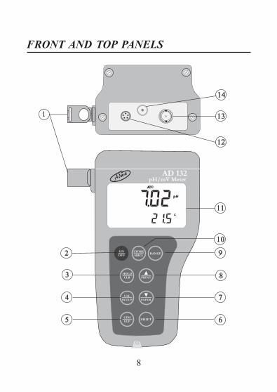
1. Holders for probes2. ON/OFF key, to turn the instrument ON and OFF3. HOLD/CLR key, to freeze stable reading on the
LCD and clear calibration or logged data4. CAL/SETUP key, to enter/exit calibration mode or
enter/exit SETUP mode5. CFM/GLP key, to confirm value and display GLP
information6. SHIFT key, to activate the key second function.
Press first SHIFT and then the selected key. TheSHIFT tag is displayed until the second key is pressed
7. DOWN arrow/PAPER (PAPER for AD132 only)to manually decrease the value of temperature orother parameters, or to pull out printer paper
8. UP arrow/PRINT (PRINT for AD132 only) key, tomanually increase the value of temperature or otherparameters, to obtain a printout or cancel printing
9. RANGE key, to select measurement range or switchfocused data
10. STORE/MRCL key, to store measured data andenter/exit the logged data viewing mode
11. Liquid Crystal Display (LCD)12. RS232 connector (AD132 only)13. BNC connector for pH or ORP electrodes14. Temperature probe socket
10
OPERATIONAL GUIDE
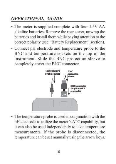
• The meter is supplied complete with four 1.5V AAalkaline batteries. Remove the rear cover, unwrap thebatteries and install them while paying attention to thecorrect polarity (see “Battery Replacement” section).
• Connect pH electrode and temperature probe to theBNC and temperature sockets on the top of theinstrument. Slide the BNC protection sleeve tocompletely cover the BNC connector.
• The temperature probe is used in conjunction with thepH electrode to utilize the meter’s ATC capability, butit can also be used independently to take temperaturemeasurements. If the probe is disconnected, thetemperature can be set manually using the arrow keys.
11
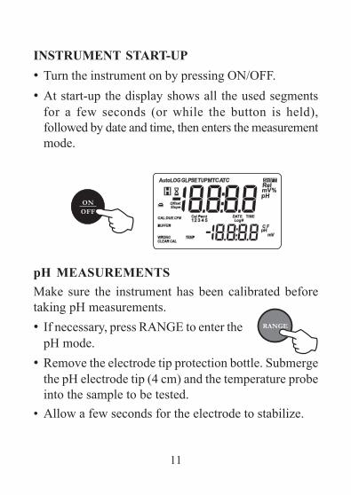
INSTRUMENT START-UP• Turn the instrument on by pressing ON/OFF.• At start-up the display shows all the used segments
for a few seconds (or while the button is held),followed by date and time, then enters the measurementmode.
pH MEASUREMENTSMake sure the instrument has been calibrated beforetaking pH measurements.• If necessary, press RANGE to enter the
pH mode.• Remove the electrode tip protection bottle. Submerge
the pH electrode tip (4 cm) and the temperature probeinto the sample to be tested.
• Allow a few seconds for the electrode to stabilize.

12
• The pH reading is displayed on the primaryLCD and the temperature on thesecondary LCD.
• If measurements are taken successively in differentsamples, it is recommended to rinse the electrodethoroughly with deionized or tap water. Then to conditionthe electrode, rinse it with some of the next sample tobe measured before immersing it into the solution.
• Since the pH reading is affected by temperature, inorder to measure the pH accurately, the meter is providedwith temperature compensation feature. To use theautomatic temperature compensation (ATC) feature,connect and immerse the AD7662 temperature probeinto the sample as close as possible to the electrodeand wait for a few seconds.

13
• If the temperature of the sample is known, manualtemperature compensation (MTC) can be performed.Disconnect the temperature probe and the display willshow the default temperature of 25 °C (77 °F) or thelast temperature reading with the °C (or °F) tag blinking.
• The temperature value can be adjusted using the arrowkeys.
ORP (mV) MEASUREMENTSOxidation- reduction potential (REDOX) measurementsprovide the quantification of the oxidizing or reducingpower of the tested sample.To correct perform a redox measurement, the surfaceof the ORP electrode must be clean and smooth.• Press RANGE to enter the mV mode.• Immerse the tip of the ORP electrode at
least 4 cm into the solution to be testedand wait a few seconds for the reading tostabilize.
• The instrument displays the mV reading on the primaryLCD and the temperature on the secondary LCD.

14
• If the reading is out of range, the closest full-scalevalue will be displayed blinking on the primary LCD.
RELATIVE mV MEASUREMENTSTo enter the relative mV mode, press the RANGE key.The relative mV reading will be displayed on theprimary LCD and the current temperature value on thesecondary LCD.The relative mV reading is equal to the differencebetween the absolute mV input value and relative mVoffset established in the relative mV calibration.
15
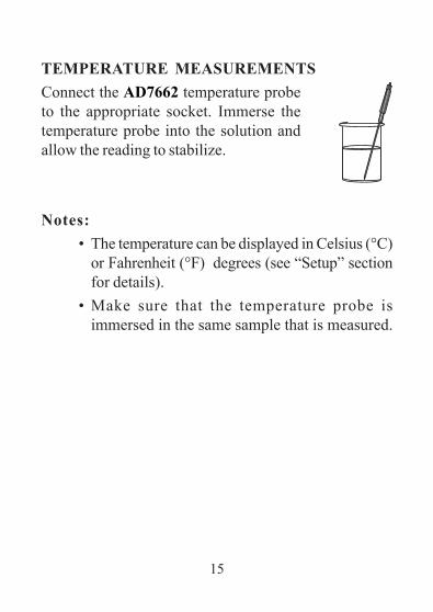
TEMPERATURE MEASUREMENTSConnect the AD7662 temperature probeto the appropriate socket. Immerse thetemperature probe into the solution andallow the reading to stabilize.
Notes:• The temperature can be displayed in Celsius (°C)
or Fahrenheit (°F) degrees (see “Setup” sectionfor details).
• Make sure that the temperature probe isimmersed in the same sample that is measured.

16
pH CALIBRATION
The instrument should be recalibrated:• Whenever the pH electrode is replaced• At least once a week• After testing aggressive chemicals• If the “CAL DUE” message blinks during measurement
PREPARATIONPour small quantities of the buffer solutions into cleanbeakers. If possible, use plastic beakers to minimize anyEMC interferences.For accurate calibration, use two beakers for each buffersolution: the first one for rinsing the electrode and thesecond for calibration.If you are measuring in the acidic range, use pH 4.01 or1.68 as second buffer. If you are measuring in the alkalinerange, use 10.01/9.18 or 12.45 as second buffer.For extended range measurements (acidic and alkaline),perform a five-point calibration by selecting five of theavailable buffers.
17
PROCEDUREThe meter allows to choose among 7 memorized buffervalues: pH 1.68, 4.01, 6.86, 7.01, 9.18, 10.01 and 12.45.For accurate measurements it is recommended toperform a five-point procedure. However, at least atwo-point calibration is suggested.The instrument will automatically skip the buffers alreadyused and require a minimum difference of 0.2 pH unitbetween two buffers used for calibration.A new calibration will override existing stored calibrationdata. The slopes adjacent to the calibration points will bereevaluated.If the new calibration point has no correspondence inthe existing stored calibration data, it is simply added orthe instrument will ask which buffer will be replaced bythe current one.If at least a two-point calibration has been performedand an offset correction of the electrode is desired, keepingunchanged the existing slopes, perform a one-pointcalibration selecting the “OFFS” option in the setup menu.If the “Pnt” option is selected, the slopes adjacent to thecalibration points will be reevaluated.

18
FIVE-POINT CALIBRATION• Immerse the pH electrode and the
temperature probe approximately 4 cminto the first buffer solution (pH 1.68,4.01, 6.86, 7.01, 10.01 or 12.45) and stirgently. The temperature probe shouldbe close to the pH electrode.
• To enter the pH calibration mode, pressCAL from pH measurement mode.
• The instrument will display the measured pH on theprimary LCD and the “7.01 pH” buffer on thesecondary LCD, together with “CAL” and “Cal Point1” tags.
• If necessary, use the arrow keys to select a differentbuffer value.

19
• The hourglass symbol will blink on the LCD until thereading is stable.
• When the reading is stable and closeto the selected buffer, the “CFM” tagblinks. Press the CFM key to confirmcalibration.
• The calibrated value is then displayed on the primaryLCD and the secondary LCD shows the secondexpected buffer value, together with the “CAL” and“Cal Point 2” tags.
Note: If the buffer is not recognized, the “WRONG”message blinks to advise the user. Change bufferand proceed.
• After the first calibration point is confirmed, immersethe pH electrode and the temperature probe approximately4 cm into the second buffer solution and stir gently.The temperature probe should be close to the pHelectrode.

20
• If necessary, use the arrow keys to select a differentbuffer value.
• The hourglass symbol will blink on the LCD until thereading is stable.
• When the reading is stable and closeto the selected buffer, the “CFM” tagblinks (or “WRONG” for buffer notrecognized). Press the CFM key toconfirm calibration.
• The calibrated value is then displayed on the primaryLCD and the secondary LCD shows the third expectedbuffer value.
• After the second calibration point is confirmed,immerse the pH electrode and the temperature probeapproximately 4 cm into the third buffer solution andstir gently. The temperature probe should be close tothe pH electrode.
• If necessary, use the arrow keys to select a differentbuffer value.
• The hourglass symbol will blink on the LCD until thereading is stable.
• When the reading is stable and close to the selectedbuffer, the “CFM” tag blinks (or “WRONG” for buffer

21
not recognized). Press the CFM key toconfirm calibration.
• The calibrated value is then displayedon the primary LCD and the secondaryLCD shows the fourth expected buffervalue.
• After the third calibration point is confirmed, immersethe pH electrode and the temperature probe approximately4 cm into the third buffer solution and stir gently. Thetemperature probe should be close to the pH electrode.
• If necessary, use the arrow keys to select a differentbuffer value.
• The hourglass symbol will blink on the LCD until thereading is stable.
• When the reading is stable and closeto the selected buffer, the “CFM” tagblinks (or “WRONG” for buffer notrecognized). Press the CFM key toconfirm calibration.
• The calibrated value is then displayed on the primaryLCD and the secondary LCD shows the fifth expectedbuffer value.

22
• After the fourth calibration point is confirmed, immersethe pH electrode and the temperature probe approximately4 cm into the third buffer solution and stir gently. Thetemperature probe should be close to the pH electrode.
• If necessary, use the arrow keys to select a differentbuffer value.
• The hourglass symbol will blink on the LCD until thereading is stable.
• When the reading is stable and closeto the selected buffer, the “CFM” tagblinks (or “WRONG” for buffer notrecognized). Press the CFM key toconfirm calibration.
• The instrument stores the calibration values andreturns to normal measurement mode.
FOUR, THREE or TWO-POINT CALIBRATIONProceed as described in the “Five-point calibration” sectionand press CAL after the appropriate accepted calibrationpoint. The instrument will memorize the calibration dataand return to normal measurement mode.
23
ONE-POINT CALIBRATION• Two setup options are available: “Pnt” and “OFFS”.• If the “Pnt” option is selected, the adjacent slopes will
be reevaluated.• If the “OFFS” option is selected, an electrode offset
correction is performed keeping unchanged the existingslopes.
• Proceed as described in the “Five-point calibration”section and press CAL after the first acceptedcalibration point. The instrument will memorize thesingle point calibration data and return to normalmeasurement mode.
Notes:• Press RANGE to toggle between pH buffer and
temperature reading during calibration.• Each time a buffer is confirmed, the new
calibration parameters replace the old data ofthe corresponding buffer.
• If current confirmed buffer has no correspondencein the stored calibration, it will be added to theexisting calibration data. If the stored calibrationis a five-point procedure, the instrument will askwhich buffer should be replaced.

24
Use the arrow keys to select the buffer to bereplaced, then press CFM to confirm or CAL toexit calibration without replacing.
CLEAR CALIBRATIONIf the SHIFT and CLR keys are pressed at any timeduring calibration, the “CLEAR CAL” tag lights up andthe “donE” message is displayed on the secondary LCD.All previous calibrations are cleared and the instrumentcontinues the procedure. The points already confirmedfor the current calibration are not deleted.The “CAL DUE” message will blinks in measurementmode to advise the user that a pH calibration is required.Note: If SHIFT and CLEAR are pressed during the
first calibration point, the instrument returns tomeasurement mode.

25
RELATIVE mV CALIBRATION
• To enter relative mV calibration mode, press CAL fromrelative mV measurement mode. The relative mV isdisplayed on the primary LCD and the absolute mVvalue on the secondary LCD.
• Use the arrow keys to change the displayed relativemV value.
• When the reading is stable and the relative mV offsetis inside the offset window (±200.0 mV), the CFMtag will be displayed.
• Press CFM to confirm relative mV calibration and theinstrument will return to normal measurement mode.
• If the absolute mV reading is out of range or the relativemV offset is out of the offset window, the WRONGtag will blink. Change the input value or the relativemV offset to complete the calibration procedure.

26
GOOD LABORATORY PRACTICE (GLP)GLP is a set of functions that allows data storage (andretrieval) about the electrode status and maintenance.All data regarding pH and relative mV calibrations arestored in the instrument memory.To enter GLP mode, press SHIFT and then GLP key.If no calibration has been performed, the “no CAL”message will blink.
CALIBRATION TIME-OUT ALARMThe instrument allows to set the number of days (from1 to 7) before the next required pH calibration. Thedefault setting is “OFF” (disabled).At start-up the instrument checks if the calibration time-outhas expired. If yes, the “CAL DUE” message blinks toadvise the user that a new calibration is required.

27
Note: If the instrument was not calibrated or allcalibration data were cleared, the “CAL DUE”message is displayed even if the feature isdisabled in the setup menu.
LAST pH CALIBRATION DATAThe last pH calibration data are stored automatically aftera successful calibration.To view the pH calibration data, from pH measurementmode press SHIFT and then GLP key. The instrumentwill display the date (yyyy.mm.dd) of last calibration.
Use the up arrow key to view all calibration parametersin the following sequence:• The time (hh:mm) of the
last calibration.

28
• The pH calibration offset.
• pH calibration slope (theGLP slope is the averageof the calibration slopes;the percentage is referredto the ideal value of 59.16mV/pH).
• Calibration buffers in the order used for calibration,together with the corresponding warnings.
• Calibration time-out alarmstatus. The display shows“OFF” if the feature isdisabled, or the daysremaining before thecalibration alarm will beactivated, or after thecalibration is expired (e.g. -3).

29
Notes:• The “OLd” message displayed beside a buffer
value means that this buffer was not used duringlast calibration. Press SHIFT and then SETUPkey to see the old calibration date (or time, if oldcalibration date is the same as the last procedure).
• The “no buF” message means that calibrationwas performed at less than five points.
• The instrument ID.

30
LAST RELATIVE mV CALIBRATION DATALast relative mV calibration data are stored automaticallyafter a successful calibration.To view the relative mV calibration data, from normalrelative mV measurement mode press SHIFT and thenGLP key. The instrument will display the date(yyyy.mm.dd) of the last calibration.Use the up arrow key to view all logged calibrationparameters in the following sequence:• Last calibration date and time• Relative mV calibration offset• Instrument ID as in pH GLP modePress SHIFT and then GLP key at any moment toreturn to normal measurement mode.

31
SETUPSetup mode allows viewing and modifying the followingparameters:
• Calibration alarm time-out• One-point calibration behavior• Temperature measure unit• Current date (yyyy.mm.dd)• Current time (hh:mm)• Printer status (AD132 only)• Auto-off• Baud rate (serial communication, AD132 only)• Command prefix (serial communication, AD132 only)• Instrument ID
• To enter SETUP mode, from measurement mode pressSHIFT and then SETUP.
• Press CAL to change theitem value. The selecteditem (e.g. hour, whilesetting the time) and“CFM” tag will blink.
• Use the arrow keys toscroll the available values.
32
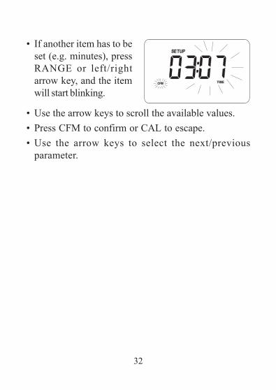
• If another item has to beset (e.g. minutes), pressRANGE or left/rightarrow key, and the itemwill start blinking.
• Use the arrow keys to scroll the available values.• Press CFM to confirm or CAL to escape.• Use the arrow keys to select the next/previous
parameter.

33
Item Description Valid values DefaultCAL DUE Time-out alarm OFF, 1 to 7 days OFF1 Pnt 1-point cal. behavior Pnt, OFFS PnttEMP Temperature unit °C, °F °CDate Date (yyyy.mm.dd) 2000.01.01 2004.01.01
to 2099.12.31Time Time (hh:mm) 00:00 to 23:59 00:00
Printer status ON, OFF OFF(AD132 only)bAUd Baud rate 600, 1200, 2400 2400(AD132 only) 4800, 9600PrEF Command prefix 0 to 47 16(AD132 only)AOFF Auto-off no or 5 minutes noIn Id Instrument ID 0000 to 9999 0000
The following table lists all the available SETUP parameters,their valid values and the factory settings (default):

34
LOG-ON-DEMAND
This feature allows the user to log pH and Rel mVmeasurements, together with temperature.Moreover, for AD132 all logged data can be transferredto a PC or printed through the RS232 port.Both models AD131 and AD132 can store up to 500samples into memory.
LOGGINGTo store the current reading into memory,press the STORE key from measurementmode.The instrument displays the current date (mm.dd) on theprimary LCD, while the secondary LCD shows therecord number with the “LOG” tag blinking for a fewseconds and then the number of free locations.
35
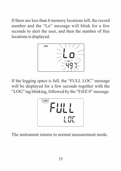
If there are less than 6 memory locations left, the recordnumber and the “Lo” message will blink for a fewseconds to alert the user, and then the number of freelocations is displayed.
If the logging space is full, the “FULL LOC” messagewill be displayed for a few seconds together with the“LOG” tag blinking, followed by the “FrEE 0” message.
The instrument returns to normal measurement mode.

36
VIEWING LOGGED DATATo retrieve the information stored, press SHIFT and thenMRCL from measurement mode. If no data were logged,the “no rEC” message blinks on the LCD.
Otherwise, the instrument displays the memorized pHor relative mV reading, and the lot number.
Pressing SHIFT and then SETUP key while in memoryrecall mode, the secondary LCD will toggle betweenthe lot and the record number. Use the arrow keys toselect a different lot or record.

37
Press RANGE key to scroll all logged parameters,displayed as shown in the table below:
Parameter Primary LCD Secondary LCDmV mV reading TemperatureTIME Hour & minutes SecondsDATE Year Month & dayOFFSET Offset value Lot or record numberSLOPE Slope value Lot number
Notes:• To view the previous logged parameter, press
the left arrow key.• In relative mV memory recall mode, the offset
value is not available and the display showsdashes “----”.
• The record number is an identification numberinside a lot.
After scrolling all logged parameters, the meter displaysthe “dEL” message together with the lot number.Note: Pressing SHIFT and then SETUP key, the
instrument toggles between record number and“del ALL”.

38
• Press SHIFT and then CLEAR to delete the selectedrecord or all records.
Note: Positions remain free in the log-on-demand lotby deleting the last logged sample or all lot.
• If the “dEL All” option was selected, all logged dataare deleted and the instrument returns to normalmeasurement mode.
• Press SHIFT and MRCL at any time to return tomeasurement mode.
39
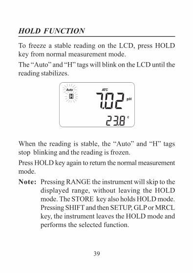
HOLD FUNCTION
To freeze a stable reading on the LCD, press HOLDkey from normal measurement mode.The “Auto” and “H” tags will blink on the LCD until thereading stabilizes.
When the reading is stable, the “Auto” and “H” tagsstop blinking and the reading is frozen.Press HOLD key again to return the normal measurementmode.Note: Pressing RANGE the instrument will skip to the
displayed range, without leaving the HOLDmode. The STORE key also holds HOLD mode.Pressing SHIFT and then SETUP, GLP or MRCLkey, the instrument leaves the HOLD mode andperforms the selected function.

40
PRINTING (AD132 only)When connected to an external serial printer, a completeset of information can be printed.Printer specifications:• at least 16 characters / line• baud rate 9600• 9-pin RS232 inputData can be printed on demand (from measurement, GLPand SETUP modes) by pressing SHIFT and then PRINT.Note: To cancel printing, press SHIFT and then PRINT
again.
While in pH measurement mode,the printout provides the followinginformation:
When in GLP mode, the printout provide the followinginformation:
Date 2004/01/01Time 02:25:17pH 7.01mV -23.2°C 26.3

41
• For pH range:
• For relative mV range:
• Setup mode: if SHIFT andPRINT are the first keys pressedafter entering the setup mode, asetup table of contents will beprinted:
GLP Rel mVInstr ID 0003Date 2004/01/01Time 02:27:35Off.RelmV -23.3
INSTRUMENT SETUPCalibration Alarm Time OutOne point cal behaviorTemperature unitCurrent DateCurrent TimePrinter ON/OFFAutoOff 5/NOBaud rateCommand prefixInstrument IDCAL-enter in modifying modeSET-exit SETUPRANGE-select parameter See also items Help printings
GLP pHInstr ID 0003Date 2004/01/01Time 01:04:32Cal Time Out OFFOffset -22.9mVSlope 100.0%Cal Buffers:pH 7.01

42
• When exiting the setupmode, the instrumentasks if the setup reporthas to be printed. The“Prn” message will bedisplayed, together withthe printer symbol ( )and the CFM tag blinking.
• Press CFM to print thesetup report or CAL toexit without printing.
SETUP REPORTInstr ID 0003Cal Time Out OFFOne Cal Point pntDate 2004/01/01Time 02:28:34Printer ONAuto-off noBaud Rate 2400Comm prefix 16Temperature °C

43
From setup mode, if CAL and thenPRINT is pressed for a chosenparameter, a help printout will providethe following information (e.g. AlarmTime-Out):
When in logging mode, an automaticprintout will provide the followinginformation for pH and mV:
SETALARM TIME OUT (OFF or 1-7)Active Keys: ̂ -increment v -decrementCAL-exit, no saveCFM-save & exitCLR-set to default
Date 2004/01/01Time 01:13:53pH 7.01mV -23.3°C 26.2
44
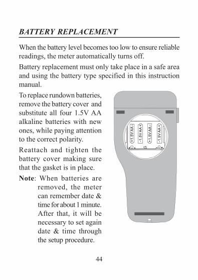
BATTERY REPLACEMENT
When the battery level becomes too low to ensure reliablereadings, the meter automatically turns off.Battery replacement must only take place in a safe areaand using the battery type specified in this instructionmanual.To replace rundown batteries,remove the battery cover andsubstitute all four 1.5V AAalkaline batteries with newones, while paying attentionto the correct polarity.Reattach and tighten thebattery cover making surethat the gasket is in place.Note: When batteries are
removed, the metercan remember date &time for about 1 minute.After that, it will benecessary to set againdate & time throughthe setup procedure.

45
TEMPERATURE CALIBRATION(for technical personnel only)
The instruments are factory calibrated for temperature.Adwa’s temperature probes are interchangeable and notemperature calibration is needed when they are replaced.If temperature measurements are not accurate, temperaturenew calibration should be performed.For an accurate recalibration, contact your dealer or thenearest Adwa Customer Service Center, or follow theinstructions below.• Prepare a vessel containing ice and water, and
another one containing hot water at approximately50°C (122°F). Place insulation material around thevessels to minimize temperature drift.
• Use a calibrated thermometer with a resolution of 0.1 °C(or 0.1 °F) as reference thermometer. Connect thesupplied AD7662 temperature probe to the appropriatesocket on the rear panel.
• With the instrument off, press and hold the CAL & uparrow keys, then power on the instrument. The “CAL”tag lights up and the secondary LCD shows 0.0 °C (or32.0 °F). The primary LCD will display the measuredtemperature or “----”, if the reading is out of range.

46
• Immerse the temperature probe into the vessel withice and water as close as possible to the referencethermometer. Allow a few seconds for probe thermalstabilization.
• Use the arrow keys to set the reading on the secondaryLCD to that measured by the reference thermometer.
• When the reading is stable and close to the selectedcalibration point, the CFM tag starts blinking.
• Press CFM to confirm. The secondaryLCD will display 50.0°C (or 122.0°F).
• Immerse the temperature probe into the second vesselas close as possible to the reference thermometer.Allow a few seconds for probe thermal stabilization.
• Use the arrow keys to set the reading on the secondaryLCD to that of the hot water measured by the referencethermometer.
• When the reading is stable and close to the selectedcalibration point, the CFM tag starts blinking.

47
• Press CFM to confirm. The instrumentreturns to normal measurement mode.
Notes:• If the reading is not close to the selected
calibration point, the WRONG tag will blink.Change the temperature probe and restartcalibration.
• Press CAL at any time to quit the procedure.
mV CALIBRATION (for technical personnel only)
The instruments are factory calibrated for mV range.Adwa’s ORP electrodes are interchangeable and no mVcalibration is needed when they are replaced.If measurements are not accurate, a mV recalibrationshould be performed.For an accurate recalibration, contact your dealer or thenearest Adwa Customer Service Center, or follow theinstructions below.A two or three-point procedure can be performed at 0.0,600.0 and 1800 mV.
48
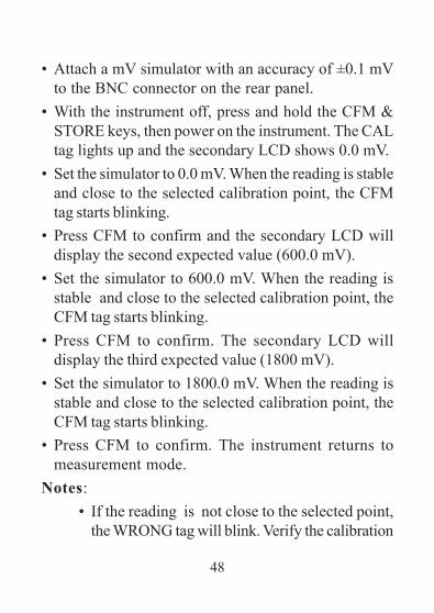
• Attach a mV simulator with an accuracy of ±0.1 mVto the BNC connector on the rear panel.
• With the instrument off, press and hold the CFM &STORE keys, then power on the instrument. The CALtag lights up and the secondary LCD shows 0.0 mV.
• Set the simulator to 0.0 mV. When the reading is stableand close to the selected calibration point, the CFMtag starts blinking.
• Press CFM to confirm and the secondary LCD willdisplay the second expected value (600.0 mV).
• Set the simulator to 600.0 mV. When the reading isstable and close to the selected calibration point, theCFM tag starts blinking.
• Press CFM to confirm. The secondary LCD willdisplay the third expected value (1800 mV).
• Set the simulator to 1800.0 mV. When the reading isstable and close to the selected calibration point, theCFM tag starts blinking.
• Press CFM to confirm. The instrument returns tomeasurement mode.
Notes:• If the reading is not close to the selected point,
the WRONG tag will blink. Verify the calibration

49
PC INTERFACE (AD132 only)Data can be transferred from the instrument to the PCusing the ADSW10 Windows® compatible software(optional).ADSW10 also offers graphing and on-line help feature.Data can be exported to the most popular spreadsheetprograms for further analysis.To connect your instrument to a PC, use the AD9551optional Adwa cable. Make sure that the instrument isswitched off and plug the cable to the instrument RS232socket and to a serial port of your PC.If not using the AD9551 cable, communication betweeninstrument and PC may be not possible, due to differentRS232 connector configuration.
conditions or contact your dealer if calibrationcan not be performed.
• To return to normal measurement mode, pressCAL at any moment during calibration.
• If the calibration procedure is ended after the600.0 mV point is confirmed, the meter returnsto normal measurement mode and stores a 2-point calibration data.

50
pH ELECTRODE CONDITIONING &MAINTENANCE
PREPARATION PROCEDURERemove the pH electrode protective cap. DO NOT BEALARMED IF SALT DEPOSITS ARE PRESENT.This is normal with electrodes and they will disappearwhen rinsed with water.During transport, tiny bubbles of air may form inside theglass bulb affecting proper functioning of the electrode.These bubbles can be removed by “shaking down” theelectrode as you would do with a glass thermometer.If the bulb and/or junction are dry, soak the electrode inAD70300 storage solution for at least one hour.
STORAGE PROCEDURETo minimize clogging and assure a quick response time,the glass bulb and the junction of the pH electrode shouldbe kept moist and not allowed to dry out.Replace the solution in the protective cap with a fewdrops of AD70300 storage solution .
NEVER STORE THE ELECTRODE IN DISTILLEDOR DEIONIZED WATER.

51
PERIODIC MAINTENANCEInspect electrode and cable. The cable used forconnection to the instrument must be intact and theremust be no points of broken insulation on the cable orcracks on the electrode stem or bulb. Connectors mustbe perfectly clean and dry. If any scratches or cracksare present, replace the electrode. Rinse off any saltdeposits with water.
CLEANING PROCEDURESoak in AD7061 general cleaning solution for approximately30 minutes.IMPORTANT: After performing any of the cleaningprocedures, rinse the electrode thoroughly with AD7000,refill the reference chamber with fresh electrolyte andsoak the electrode in AD70300 storage solution for atleast 1 hour before taking measurements.

52
TROUBLESHOOTING GUIDE SYMPTOMSSlow response/excessive drift.
Readingsfluctuate up anddown (noise).
Only blinkingdashes duringpH measure-ments.
Blinking readingduring measure-ments.Out of range inthe mV scale.
PROBLEMDirty pH electrode.
Clogged/dirtyjunction. Lowelectrolyte level(for refillableelectrodes only).Out of range in thepH scale.
Reading out ofrange or electrodenot connected.Dry membrane/junction.
SOLUTIONSoak in AD7000solution for 30minutes and thenclean the electrode.Clean the electrode.Refill with freshsolution (forrefillable electrodesonly).Make sure the pHsample is in thespecified range.Calibrate. Checkelectrolyte leveland general stateof the electrode.Check sample orconnect electrode.
Soak in AD70300storage solutionfor 1 h.

53
SYMPTOMSThe meter doesnot work withtemperatureprobe.The meter fails tocalibrate or givesfaulty readings.Explicit warningsare displayedduring pHcalibration.At start-up themeter displays allLCD perma-nently.“Prn Eror” errormessage dis-played.
“Err xx” errormessage dis-played.
PROBLEMOut of ordertemperature probe.
Broken or out oforder pH electrode.
Dirty/broken pHelectrode, contami-nated reference orbuffers.One of the keys isblocked.
Printer error.
Internal error.
SOLUTIONReplace the probe.
Replace theelectrode.
Follow displayedinstructions.
Check thekeyboard orcontact thevendor.Turn the meter offand then turn iton. If the errorpersist, contactyour dealer.Turn the meter offand then turn iton. If the errorpersist, contactyour dealer.
54
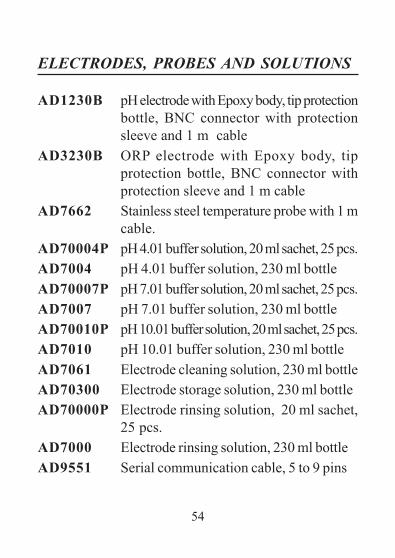
ELECTRODES, PROBES AND SOLUTIONS
AD1230B pH electrode with Epoxy body, tip protectionbottle, BNC connector with protectionsleeve and 1 m cable
AD3230B ORP electrode with Epoxy body, tipprotection bottle, BNC connector withprotection sleeve and 1 m cable
AD7662 Stainless steel temperature probe with 1 mcable.
AD70004P pH 4.01 buffer solution, 20 ml sachet, 25 pcs.AD7004 pH 4.01 buffer solution, 230 ml bottleAD70007P pH 7.01 buffer solution, 20 ml sachet, 25 pcs.AD7007 pH 7.01 buffer solution, 230 ml bottleAD70010P pH 10.01 buffer solution, 20 ml sachet, 25 pcs.AD7010 pH 10.01 buffer solution, 230 ml bottleAD7061 Electrode cleaning solution, 230 ml bottleAD70300 Electrode storage solution, 230 ml bottleAD70000P Electrode rinsing solution, 20 ml sachet,
25 pcs.AD7000 Electrode rinsing solution, 230 ml bottleAD9551 Serial communication cable, 5 to 9 pins

55

MANAD132 09/14
ADWA HUNGARY Kft.Alsókikötõ sor 11, 6726 Szeged, Hungary
Tel. +36 62 317 878Fax +36 62 550 610
www.adwainstruments.com