User manual 10500 sa p- gb
35
1 USER MANUAL 173, RUE DES FOUGERES ZONE INDUSTRIELLE LES BRACOTS 74890 BONS EN CHABLAIS France TEL 33 (0)4 50 36 13 85 FAX 33 (0)4 50 36 11 33 WEB : www.nicomatic.com CRIMPING PNEUMATIC PRESS CRIMPFLEX® TYPE : 10500 – SA/SAP Edition July 2005 – version 1.2
Transcript of User manual 10500 sa p- gb

1
USER MANUAL
173, RUE DES FOUGERES ZONE INDUSTRIELLE LES BRACOTS
74890 BONS EN CHABLAIS France
TEL 33 (0)4 50 36 13 85 FAX 33 (0)4 50 36 11 33
WEB : www.nicomatic.com
CRIMPING PNEUMATIC PRESS
CRIMPFLEX®
TYPE : 10500 – SA/SAP
Edition July 2005 – version 1.2

2
GENERAL SPECIFICATION The machine aims at selecting and crimping male or female NICOMATIC contacts CRIMPFLEX® type on jumpers or flexible circuits automatically. Male contact part number: 10241 / 10167 / 10067 / 11612 / 13595 Female contact part number : 11506 / 10025 / 14106 Square male contacts : 12410 (If equipped with square male tooling : 10500-SAP version) The number of contacts to be crimped is selected manually and can vary from 2 to 36. The jumper or flexible contact presentation is made manually by the operator as well as the cycle starting up. The contacts are moved into the tool automatically according to graduated positions on the rotative cylinder, corresponding to the required number of contacts to be crimped. This machine is also equipped with a downcounter, which allows pre-selecting a precise number of operations and stops automatically once it is back to zero. The press is operated by foot pedal. Crimping of 2 to 36 points in one press stroke. Use of toolings: Male tooling for : 10141, 10241, 10067, 10167, 12887 Female tooling for : 10025, 11506, 11612, 13595, 14106 Male tooling for square male contacts : 12410

3
CONFORMITY CERTIFICATE
The manufacturer:
NICOMATIC SA 173, RUE DES FOUGERES
ZONE INDUSTRIELLE LES BRACOTS 74890 BONS EN CHABLAIS
France states that the new material, which is indicated below:
CRIMPFLEX® CRIMPING PNEUMATIC PRESS
REFERENCED UNDER NUMBER 10500-SA(P) is certified conformable according to work hygiene and security rules which are properly applicable.
Bons en Chablais, 12.01.2004
For NICOMATIC P. NICOLLIN
President

4
OPERATING INSTRUCTIONS FOR THE FIRST USE I Air Supply The machine requires 5 to 6 bars of compressed, non-lubricated, dry air. Using any other air supply than the recommended air supply will damage the machine. II Installation
1. Remove all of the parts from the wooden crate and set up the machine onto the benchtop. There are mounting holes to attach the machine to table, but this is not required. It is recommended to install the machine on a flat and horizontal surface.
2. Place the foot pedal on the floor and attach the longest two red and blue tubes to the left side of the machine. The red tube is connected to the top port and the blue tube to the bottom port. The tubes should be pushed into the port and then checked for proper seating by pulling lightly on them to insure that they will not blow out under pressure.
3. Locate the large screw and table parts, and assemble. In some cases your machine may already have the work table installed. If so then just insert the thumb screw.
4. Attach an air hose to the quick disconnect fitting found on the right side of the
machine. Make sure to use a fitting that fits correctly to prevent personal injury and or damage to the machine.

5
SERVICE AND FINE ADJUSTMENTS
GENERAL REMARKS The machine does not require any special service and maintenance. However, we kindly recommend to proceed as follows, every time you change each reel or even periodically :
• cleaning we advise you to dismount the machine partially (see changes of types of contacts) and proceed as follows:
� remove all chips and scraps which you can find near the components, blades, slides, low crimping stop…
� oil or lubricate all moving components very slightly � check the blade condition visually
• cutting inspection The blades are spare-parts which might need to be replaced. We strongly recommend the user to check the condition of the blade or the cut quality of the parts

6

7
CHANGEOVER & SET UP REEL
1 - REMOVE THE ANCIEN REEL
• Disconnect the air supply by moving the red handle on the right side of the machine to the off position.
• Loosen the screw n°1 and remove the work driver n°2 • Rewind the contacts carefully, then to remove the reel by removing the part of
blocking n°3 2 - SET UP THE NEW REEL
• Set up the new reel of contacts (label of identification is facing you and visible from the front of the machine) and give the part of reel holder n°3. The reel must turn freely.
• Unroll and place the strip of contacts into the inlet until the work driver n°2 • Install the work driver so that the teeth on the bottom of the work driver must be
placed into the holes on the carrier strip and into the groove on the base of the machine n° 5.
• The work driver must be installed properly and completely into the right side. Hold the work driver down and turn the dial to determine if the contacts advance easily. If they do not advance try installing the work driver again.
• Turn the dial n°4, to left then to right, to insure that the contacts advance easily. • Tighten the screw n°1 and to actuate the dial n°4 again. • Turn the dial n°4 towards the full left. • Turn on the air supply and check up the pressure. It must rest between 5 and 6 bars (to
adjust if necessary). • Carry out a test of setting of 36 points. • If the crimping is defective, do the adjustment.

8

9
3 - CRIMPING SET-UP
• Remove the table n°6 and the support table n°7. • Free the two screws n°8 by keeping the compression. • Loosen the nuts n°9, then tighten or loosen of 1/8 of turn for the two screws n°10 to
keep them parallel. • Tighten the nuts n°9 and block the two screws n°8. • Carry out a test of crimping. • Test the crimping again if necessary. • Reinstall support table n°7 and the table n° 6.

10

11
4 – CHANGE NUMBER OF CONTACTS
• Disconnect the air. • Loosen the knurled knob n°12 in order to release the crown n°13. • Turn the dial to the notch n°13 corresponding to the number of contacts to crimp. • Tighten the knurled knob n°12 on the top of the work driver. • Turn on the air supply (before this always turn the dial n°4 to left) and check up the
pressure. It must rest between 5 and 6 bars. Adjust it if necessary. • Carry out a test.

12
13
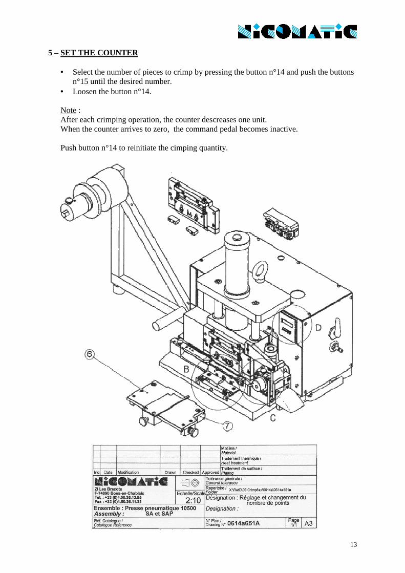
5 – SET THE COUNTER
• Select the number of pieces to crimp by pressing the button n°14 and push the buttons n°15 until the desired number.
• Loosen the button n°14. Note : After each crimping operation, the counter descreases one unit. When the counter arrives to zero, the command pedal becomes inactive. Push button n°14 to reinitiate the cimping quantity.
14
15
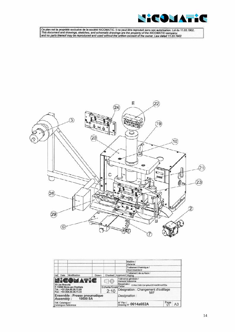
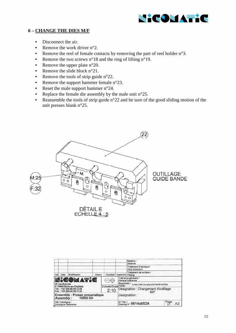
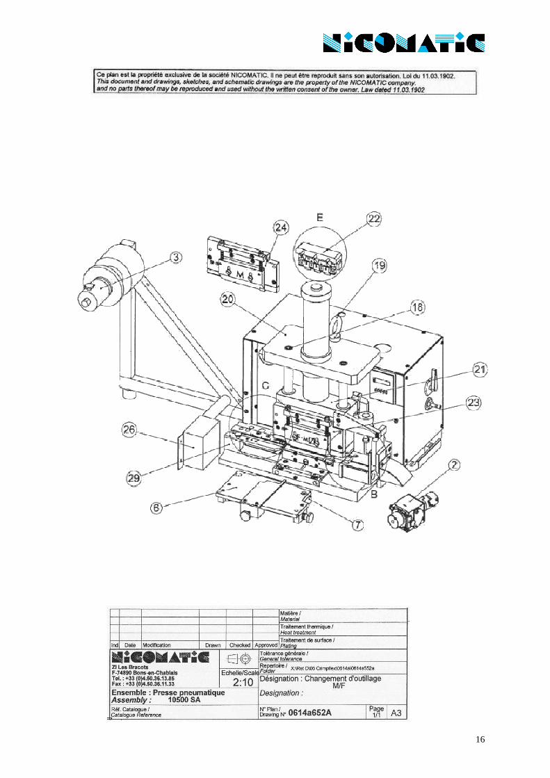
6 – CHANGE THE DIES M/F
• Disconnect the air. • Remove the work driver n°2. • Remove the reel of female contacts by removing the part of reel holder n°3. • Remove the two screws n°18 and the ring of lifting n°19. • Remove the upper plate n°20. • Remove the slide block n°21. • Remove the tools of strip guide n°22. • Remove the support hammer female n°23. • Reset the male support hammer n°24. • Replace the female die assembly by the male unit n°25. • Reassemble the tools of strip guide n°22 and be sure of the good sliding motion of the
unit presses blank n°25.
16

17
Base plate stamp
• Remove the table n°6 and the support table n°7. • Free the two screw n°8. • Loosen the screw n°16. • Withdraw the chocks n°17. • Tighten the screw n°16 to put the chocks n°17, side M in pressure. • Block the two screws n°8.

18
19
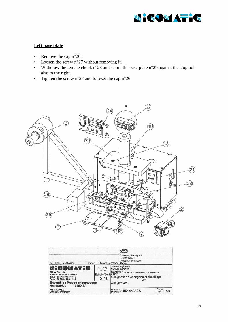
Left base plate
• Remove the cap n°26. • Loosen the screw n°27 without removing it. • Withdraw the female chock n°28 and set up the base plate n°29 against the stop bolt
also to the right. • Tighten the screw n°27 and to reset the cap n°26.

20
21
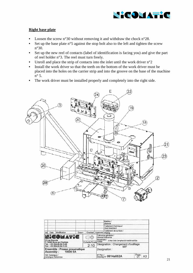
Right base plate
• Loosen the screw n°30 without removing it and withdraw the chock n°28. • Set up the base plate n°5 against the stop bolt also to the left and tighten the screw
n°30. • Set up the new reel of contacts (label of identification is facing you) and give the part
of reel holder n°3. The reel must turn freely. • Unroll and place the strip of contacts into the inlet until the work driver n°2 • Install the work driver so that the teeth on the bottom of the work driver must be
placed into the holes on the carrier strip and into the groove on the base of the machine n° 5.
• The work driver must be installed properly and completely into the right side.

22

23
• Turn the dial n°4, to left then to right, to insure that the contacts advance easily. • Tighten the screw n°1 and to actuate the dial n°4 again. • Turn the dial n°4 towards the full left. • Reset the table n°7 and the support table n°6. • Reset the slide block with the two springs and the support jack n°20 with the two
screws n°18 and the ring of lifting n°19. • Turn on the air supply and check up the pressure. It must rest between 5 and 6 bars (to
adjust if necessary). • Carry out a test of setting of 3 points before a second 36 points. • If the crimping is defective, do the adjustment.
Pass from female to male, please make the same operations but inverse.
24
25
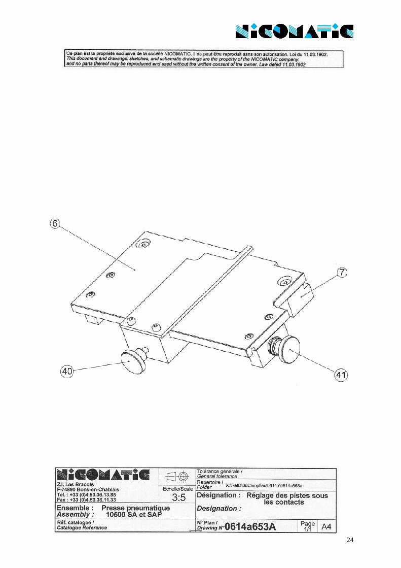
CHECK THE JUMPER CONDUCTORS ARE CENTERED UNDER THE CONTACTS:
• at each reel change • at each change of number of contacts to crimp • at each remove and setup of the work driver and when you change any tooling • at each change of lot number for cable or for circuit.
OTHERWISE:
• loosen the screws n°40 • adjust screw n°41 to right or to left to align the conductors and the contacts • tighten the screw n°40 • make a test
26
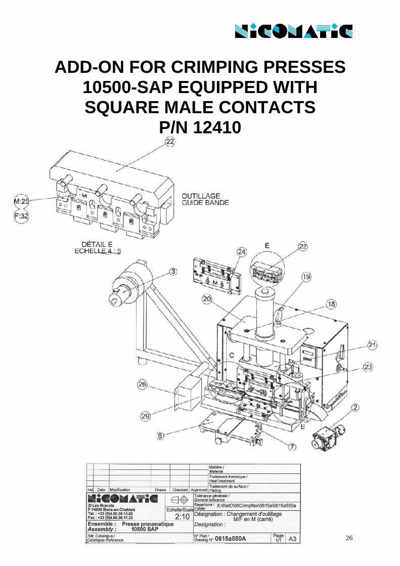
ADD-ON FOR CRIMPING PRESSES 10500-SAP EQUIPPED WITH SQUARE MALE CONTACTS
P/N 12410
27
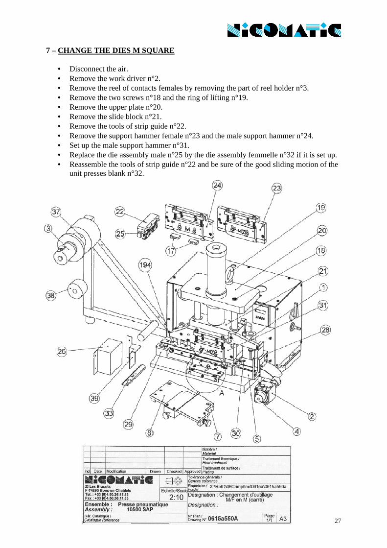
7 – CHANGE THE DIES M SQUARE
• Disconnect the air. • Remove the work driver n°2. • Remove the reel of contacts females by removing the part of reel holder n°3. • Remove the two screws n°18 and the ring of lifting n°19. • Remove the upper plate n°20. • Remove the slide block n°21. • Remove the tools of strip guide n°22. • Remove the support hammer female n°23 and the male support hammer n°24. • Set up the male support hammer n°31. • Replace the die assembly male n°25 by the die assembly femmelle n°32 if it is set up. • Reassemble the tools of strip guide n°22 and be sure of the good sliding motion of the
unit presses blank n°32.

28
29
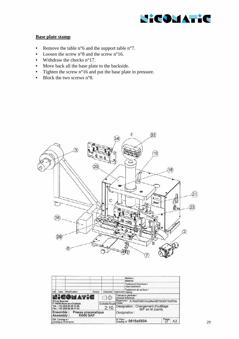
Base plate stamp
• Remove the table n°6 and the support table n°7. • Loosen the screw n°8 and the screw n°16. • Withdraw the chocks n°17. • Move back all the base plate to the backside. • Tighten the screw n°16 and put the base plate in pressure. • Block the two screws n°8.

30
31
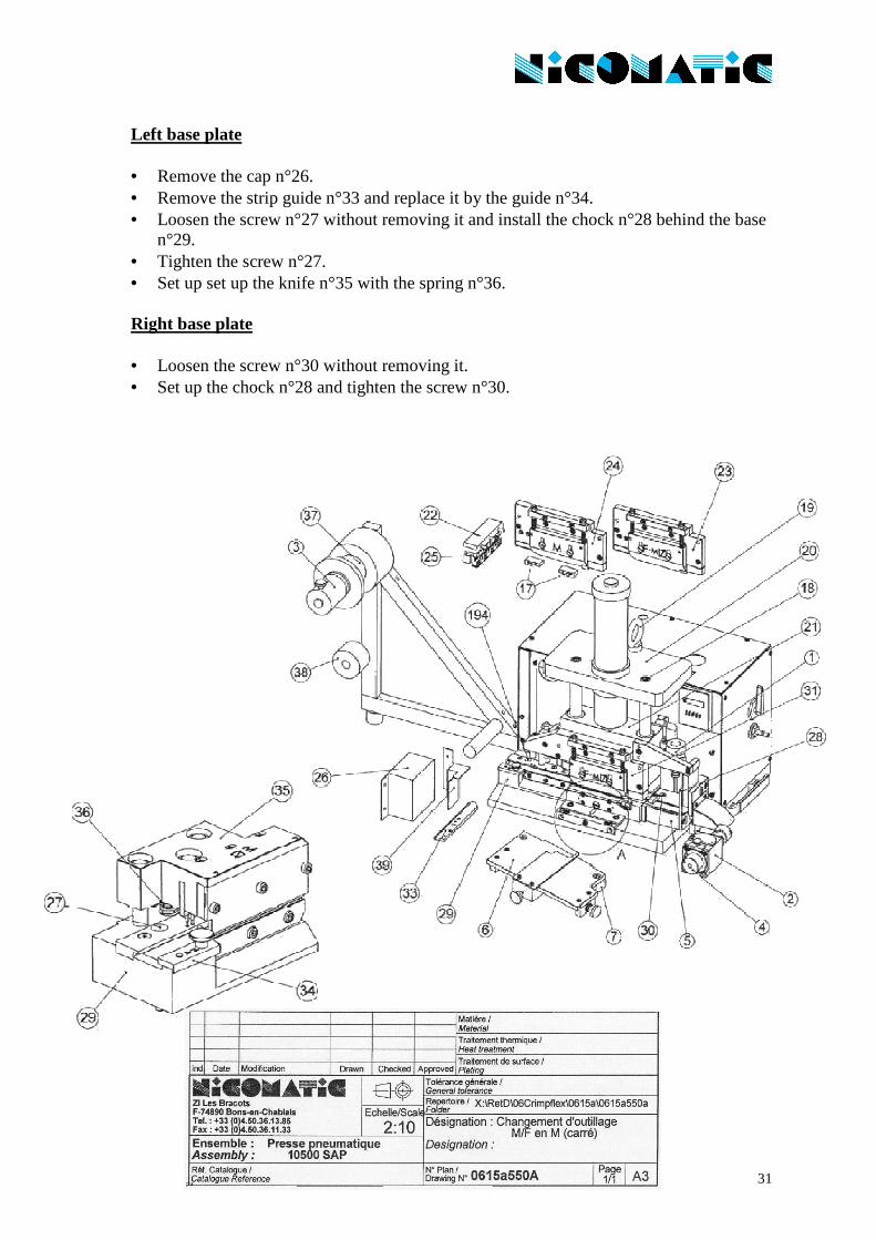
Left base plate
• Remove the cap n°26. • Remove the strip guide n°33 and replace it by the guide n°34. • Loosen the screw n°27 without removing it and install the chock n°28 behind the base
n°29. • Tighten the screw n°27. • Set up set up the knife n°35 with the spring n°36.
Right base plate
• Loosen the screw n°30 without removing it. • Set up the chock n°28 and tighten the screw n°30.

32

33
Placement of contacts • Remove the reel support n°37 and replace it by the support n°38. • Set up the reel of contacts (id label is facing you) and give the part of reel holder n°3.
The reel must turn freely. • Unroll the strip and prep the strip like indication (detail B). • Place carefully the strip of contacts into the inlet until the work driver n°2 • Install the work driver so that the teeth on the bottom of the work driver must be
placed into the holes on the carrier strip and into the groove on the base of the machine n° 5.
• The work driver must be installed properly and completely into the right side. • Turn the dial n°4, to left then to right, to insure that the contacts advance easily. • Tighten the screw n°1 and to actuate the dial n°4 again. • Turn the dial n°4 towards the full left.

34

35
• Set up table n°7 and the support table n°6. • Reset the slide block with the two springs and the support jack n°20 with the two
screws n°18 and the jack ring n°19. • Set up the case n°39. • Turn on the air supply and check up the pressure. It must rest between 5 and 6 bars (to
adjust if necessary). • Carry out a test of setting of 3 points before a second 36 points. • If the crimping is defective, do the adjustment.
Note: Take care well of the storage. Keep the parts in clean and good condition at the moment of assembly and disassembling.