User Guide Pulse Distribution Unit Model PDU-240 …...MANUAL P/N 900000154 REV A User Guide Pulse...
14
MANUAL P/N 900000154 REV A User Guide Pulse Distribution Unit Model PDU-240 P/N 018000501 Revision A May 2016 Brandywine Communications 1153 Warner Avenue Tustin, CA 92780 (714) 755 1050 (714) 755 0175 http://www.brandywinecomm.com/
Transcript of User Guide Pulse Distribution Unit Model PDU-240 …...MANUAL P/N 900000154 REV A User Guide Pulse...

MANUAL P/N 900000154 REV A
User Guide
Pulse Distribution Unit
Model PDU-240
P/N 018000501
Revision A
May 2016
Brandywine Communications1153 Warner Avenue
Tustin, CA 92780(714) 755 1050(714) 755 0175
http://www.brandywinecomm.com/

MANUAL P/N 900000154 REV A
2
Revision History
REVISION DATE COMMENTSA 5-20-2016 Original release of PDU-240 user guide.

MANUAL P/N 900000154 REV A
3
Safety Warnings
WARNING: This unit contains lethal AC voltages.Disconnect the unit from the AC supply before removingthe cover.
WARNING:The lightning flash with an arrowhead inside of an equilateral triangle isintended to alert the user to the presence of un-insulated “dangerousvoltage” within the product’s enclosure. The “dangerous voltage” may beof sufficient magnitude to constitute as a risk of electrical shock to people.
CAUTION:The exclamation point inside of an equilateral triangle is intended to alertthe user to the presence of important operation and maintenanceinstructions in the user guide.

MANUAL P/N 900000154 REV A
4
Table of Contents
1 Specifications ..................................................................................................51.1 Inputs........................................................................................................5
1.1.1 Reference Pulse Input......................................................................51.1.2 Fault Discrete (Optional)..................................................................51.1.3 Fault/Status.......................................................................................5
1.2 Outputs .....................................................................................................61.2.1 Reference Pulse Output...................................................................6
1.3 Switches and Indicators ............................................................................71.3.1 Status LED Indicators ......................................................................71.3.2 Environmental ..................................................................................71.3.3 Power ................................................................................................71.3.4 Physical.............................................................................................7
2 Option Configuration Sheet .............................................................................83 Unpacking and Installation ..............................................................................9
3.1 Unpacking.................................................................................................93.2 Installation.................................................................................................93.3 Connections............................................................................................10
3.3.1 Alarm Input Connection.................................................................104 Operation.......................................................................................................11
4.1 Powering the PDU-240 ...........................................................................114.2 Selecting the Input Reference.................................................................114.3 Fault Indicator .........................................................................................11
5 Maintenance and Troubleshooting ................................................................126 Calibration .....................................................................................................137 Drawings .......................................................................................................14

MANUAL P/N 900000154 REV A
5
1 Specifications
1.1 Inputs
1.1.1 Reference Pulse Input Pulse: 1 PPS 0.5 ppm Amplitude : 0.5 V – 1 Vrms and nominal 1 Vrms factory set Input Impedance: 50 ohm Number of Inputs: 1 with auto selection and manual override from the
front panel toggle switch Connector Type: BNC
1.1.2 Fault Discrete (Optional) Number of Inputs: 2 Level: TTL Link selectable for active high or active low Forces a changeover when active for online reference
1.1.3 Fault/Status Connector Type: DB-9 Female Mating Connector: AMP P/N 747904-2

MANUAL P/N 900000154 REV A
6
1.2 Outputs
1.2.1 Reference Pulse Output Number of Outputs: 24 Connector Type: BNC Output Protection: short circuit proof Frequencies Available (same as input):
o 1 PPSo 5 MHz
Output Level: +13 2 dBm standard and specified at time of order Stability:
o With External Reference Only:+ Same as reference
o With Free Running Internal Oscillator:+ Stability vs. Temperature: 3 x 10⁻⁹ from 0 - 60C+ Aging: 5 x 10⁻⁷ per year
Harmonic Distortion: -45 dBc Cross Talk: -80 dBc Spurious: -80 dBc Phase Noise at 1 PPS:
OFFSET (Hz) SSB PHASE NOISE dBc/Hz1 -90
10 -110100 -140
1000 -15010000 -160
MANUAL P/N 900000154 REV A
7
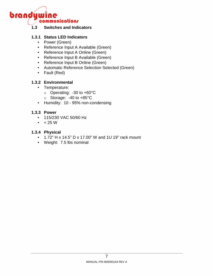
1.3 Switches and Indicators
1.3.1 Status LED Indicators Power (Green) Reference Input A Available (Green) Reference Input A Online (Green) Reference Input B Available (Green) Reference Input B Online (Green) Automatic Reference Selection Selected (Green) Fault (Red)
1.3.2 Environmental Temperature:
o Operating: -30 to +60Co Storage: -40 to +85C
Humidity: 10 - 95% non-condensing
1.3.3 Power 115/230 VAC 50/60 Hz < 25 W
1.3.4 Physical 1.72” H x 14.5” D x 17.00” W and 1U 19” rack mount Weight: 7.5 lbs nominal

MANUAL P/N 900000154 REV A
8
2 Option Configuration Sheet
PDU-240 CONFIGURATION SHEETPART NUMBER 022000002
CONNECTOR FUNCTION LEVEL INSTALLEDJ1 ALARM INPUT
PIN 1 STATUS APIN 2 STATUS BPIN 3 NO CONNPIN 4 NO CONNPIN 5 NO CONNPIN 6 GROUNDPIN 7 GROUNDPIN 8 GROUNDPIN 9 NO CONN
ACTIVE H__LACTIVE H__L
J3 REFERENCE A INPUT 1.0 Vrms
PULSE 1 PPSREFERENCEASOURCE
EXTERNAL_____ _____
FREE RUNNINGOCXO
____________
OCXO PHASELOCKED TOREFERENCE__________
J2 REFERENCE B INPUT 1.0 Vrms
PULSE 1 PPSREFERENCEBSOURCE
EXTERNAL_____ _____
FREE RUNNINGOCXO
____________
OCXO PHASELOCKED TOREFERENCE__________
J4 - J27 PULSE OUTPUT 1.0 Vrms
LEVEL 10 1 dBm
AC POWER 115 VAC

MANUAL P/N 900000154 REV A
9
3 Unpacking and Installation
3.1 Unpacking
Carefully remove the PDU-240 from its shipping carton. The following itemsshould be included in the shipment:
1 PDU-240 1 power cord 1 user guide
Note the power entry module on the rear of the PDU-240 chassis. Please takenote of the voltage displayed on the rear of the power entry module and verifythat the voltage matches the local line’s voltage.
CAUTION:THE PDU-240 WILL BE DAMAGED IF THE INCORRECT ACLINE SETTING IS USED.
WARNING:REMOVE THE POWER CORD FROM THE PDU-240 BEFOREADJUSTING THE LINE VOLTAGE.
If the AC line setting is incorrect, detach the power cord from the power entrymodule. Use a small screwdriver to lift up the fuse cover on the power entrymodule to remove the fuse holder. Reverse the fuse holder and re-insert thefuse holder, making sure that the correct AC line voltage is now displayed on therear panel.
3.2 Installation
The PDU-240 should be bolted directly into a 19” rack mount enclosure ormounted on a shelf. The PDU-240 when fully populated has up to 27 cablesattached to the rear panel, therefore it is recommended that some appropriatecable strain-relief system be used to support these cables, particularly when theunit is not supported by a shelf.

MANUAL P/N 900000154 REV A
10
3.3 Connections
Insert the power cord provided in the shipment into the rear power entry module.Connect the input reference signals to the appropriate connectors on the rearpanel.
CAUTION:FOR CORRECT OPERATION, REFERENCE PULSE AAND REFERENCE PULSE B MUST BE THE SAMEPULSE RATE, WHICH IS TYPICALLY 1 PPS.
Connect the output cables to the desired output connectors. Any unusedconnectors may be left un-terminated.
3.3.1 Alarm Input Connection
The PDU-240 may be used with an external reference such as the BrandywineCommunications GPS8 or PTS system that incorporates a discrete alarm signal.This alarm signal is used to indicate a fault (e.g. rubidium out of lock) on thereference signal, although the 1 PPS input signals may be present.
The factory standard PDU-240 configuration is a logic HI signal on the ALARM INpin indicating that the input is GOOD. A built in pull-up resistor ensures that if noALARM IN connection is made the reference is considered good. To change thepolarity of the ALARM IN, remove the top cover of the PDU-240 and set the linksto the link settings seen in the table below.
LINK SETTING REFERENCE A STATUSLK1 2-3 HI – reference A is GOODLK1 1-2 LO – reference A is GOOD
LINK SETTING REFERENCE B STATUSLK2 2-3 HI – reference B is GOODLK2 1-2 LO – reference B is GOOD
MANUAL P/N 900000154 REV A
11
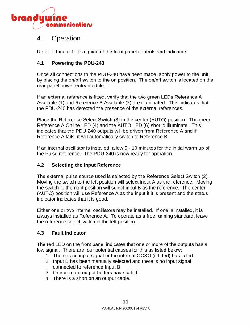
4 Operation
Refer to Figure 1 for a guide of the front panel controls and indicators.
4.1 Powering the PDU-240
Once all connections to the PDU-240 have been made, apply power to the unitby placing the on/off switch to the on position. The on/off switch is located on therear panel power entry module.
If an external reference is fitted, verify that the two green LEDs Reference AAvailable (1) and Reference B Available (2) are illuminated. This indicates thatthe PDU-240 has detected the presence of the external references.
Place the Reference Select Switch (3) in the center (AUTO) position. The greenReference A Online LED (4) and the AUTO LED (6) should illuminate. Thisindicates that the PDU-240 outputs will be driven from Reference A and ifReference A fails, it will automatically switch to Reference B.
If an internal oscillator is installed, allow 5 - 10 minutes for the initial warm up ofthe Pulse reference. The PDU-240 is now ready for operation.
4.2 Selecting the Input Reference
The external pulse source used is selected by the Reference Select Switch (3).Moving the switch to the left position will select input A as the reference. Movingthe switch to the right position will select input B as the reference. The center(AUTO) position will use Reference A as the input if it is present and the statusindicator indicates that it is good.
Either one or two internal oscillators may be installed. If one is installed, it isalways installed as Reference A. To operate as a free running standard, leavethe reference select switch in the left position.
4.3 Fault Indicator
The red LED on the front panel indicates that one or more of the outputs has alow signal. There are four potential causes for this as listed below:
1. There is no input signal or the internal OCXO (if fitted) has failed.2. Input B has been manually selected and there is no input signal
connected to reference Input B.3. One or more output buffers have failed.4. There is a short on an output cable.

MANUAL P/N 900000154 REV A
12
5 Maintenance and Troubleshooting
There is no preventive maintenance required for the PDU-240.
SYMPTOM POTENTIAL CAUSE CORRECTIVE ACTIONNo signaloutputs
1. There is no inputreference.
2. The Reference Selectswitch is selectingReference B when aninternal OCXO is used.
3. There is a failed internalsource.
1. Connect the referenceinput.
2. Select an internal source.
3. Return to factory for repair.
Fault lightilluminated
1. There is an internalOCXO failure.
2. There is a failed outputdriver.
3. There is an excessiveload on one or moreoutputs.
4. The output level isadjusted too low.
1. Return to factory for repair.
2. Return to factory for repair.
3. Disconnect the outputloads one by one until theoverloaded output isisolated. Outputs shouldnot have a load < 50 ohm.
4. Isolate the low output leveland adjust for a level thatis > 10 dBm.
MANUAL P/N 900000154 REV A
13
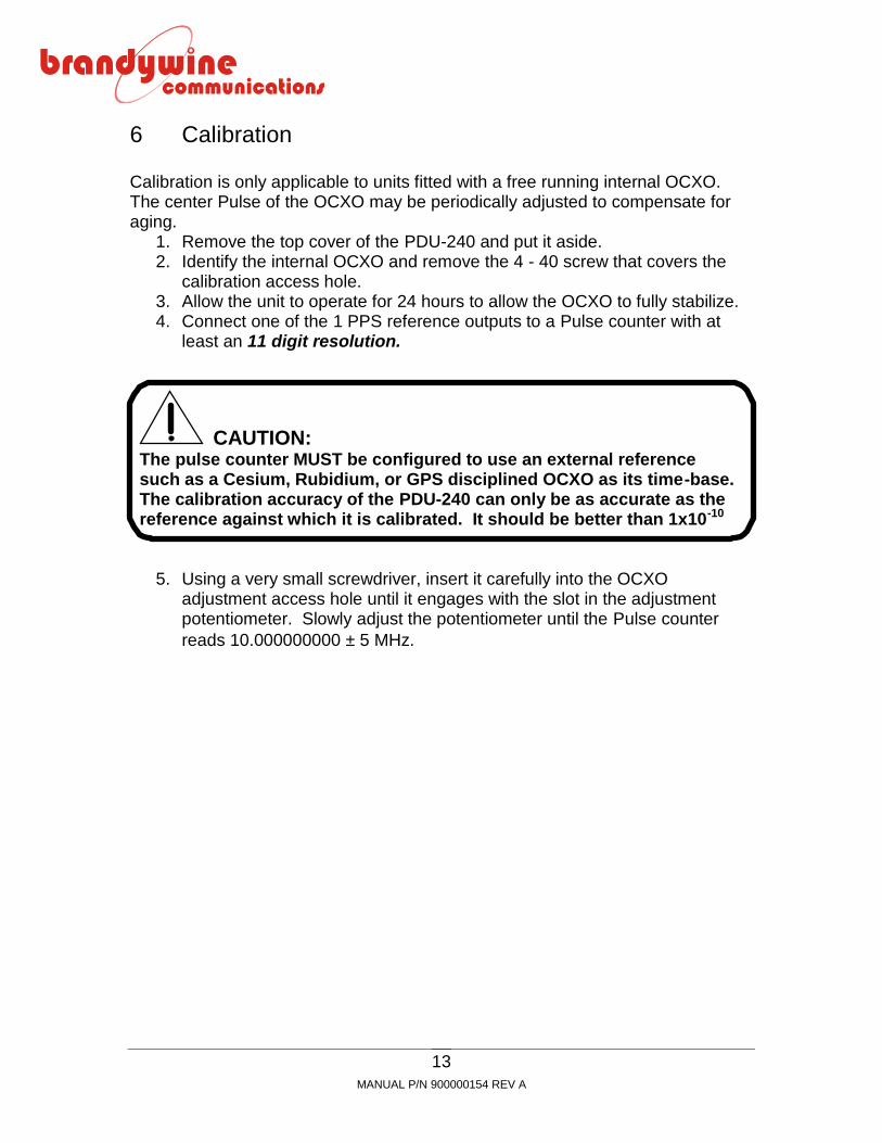
6 Calibration
Calibration is only applicable to units fitted with a free running internal OCXO.The center Pulse of the OCXO may be periodically adjusted to compensate foraging.
1. Remove the top cover of the PDU-240 and put it aside.2. Identify the internal OCXO and remove the 4 - 40 screw that covers the
calibration access hole.3. Allow the unit to operate for 24 hours to allow the OCXO to fully stabilize.4. Connect one of the 1 PPS reference outputs to a Pulse counter with at
least an 11 digit resolution.
CAUTION:The pulse counter MUST be configured to use an external referencesuch as a Cesium, Rubidium, or GPS disciplined OCXO as its time-base.The calibration accuracy of the PDU-240 can only be as accurate as thereference against which it is calibrated. It should be better than 1x10⁻¹⁰
5. Using a very small screwdriver, insert it carefully into the OCXOadjustment access hole until it engages with the slot in the adjustmentpotentiometer. Slowly adjust the potentiometer until the Pulse counterreads 10.000000000 5 MHz.

MANUAL P/N 900000154 REV A
14
7 Drawings
FIGURE DESCRIPTION1 PDU-240 Front Panel2 PDU-240 Rear Panel3 PDU-240 Mechanical Outline4 PDU-240 Link Location