
User guide - generator s VERSO 200.pdf · 1/36 Summary . 1 - Safety guidelines for installation and...
38
User guide SDMO Changeover switch VERSO 200 V 1.1a 13/11/2013 33502029301_0_1
Transcript of User guide - generator s VERSO 200.pdf · 1/36 Summary . 1 - Safety guidelines for installation and...

User guide
SDMO
Changeover switch
VERSO 200
V 1.1a13/11/2013
33502029301_0_1


1/36
Summary 1 - Safety guidelines for installation and operation ............................................................................................ 4 2 - Installation of the source changeover switch ................................................................................................. 5
2.1 - Wall-mounted unit .................................................................................................................................... 5 2.2 - Floor-mounted cabinet .............................................................................................................................. 5 2.3 - Unit dimensions and weights .................................................................................................................... 5
3 - Electrical connections for the source changeover switch ................................................................................ 6 3.1 - Preliminary checks .................................................................................................................................... 6 3.2 - Securing voltage sources ........................................................................................................................... 6 3.3 - Power connections .................................................................................................................................... 7
3.3.1 - Upstream connections (mains and generating set) .............................................................................................. 7 3.3.2 - Downstream connections (use) ........................................................................................................................... 7 3.3.3 - Tightening torque ............................................................................................................................................... 8 3.3.4 - Auxiliary connections ......................................................................................................................................... 8
3.4 - Remote control connections ...................................................................................................................... 8 3.4.1 - External starting command ................................................................................................................................. 8 3.4.2 - Options ............................................................................................................................................................... 8
4 - Description of the electronic module .............................................................................................................. 8 5 - Switching on the source changeover switch ................................................................................................. 10
5.1 - Preliminary checks .................................................................................................................................. 10 5.2 - Switching to the mains ............................................................................................................................ 10 5.3 - Switching on the generating set .............................................................................................................. 12
6 - Using the Verso 200 module .......................................................................................................................... 13 6.1 - Reading the electrical ratings .................................................................................................................. 13
6.1.1 - Three-phase source with a neutral point ........................................................................................................... 13 6.1.2 - Three-phase source without a neutral point ...................................................................................................... 13 6.1.3 - Two-phase source with a neutral point ............................................................................................................. 13 6.1.4 - Single-phase source .......................................................................................................................................... 14
6.2 - Operating modes ..................................................................................................................................... 14 6.2.1 - "AUTO" Mode ................................................................................................................................................. 14 6.2.2 - "Forcing source 1" mode .................................................................................................................................. 14 6.2.3 - "Forcing source 2" mode .................................................................................................................................. 14 6.2.4 - "TEST" Mode ................................................................................................................................................... 14
6.3 - Alarms and faults display ........................................................................................................................ 15 6.3.1 - Alarms .............................................................................................................................................................. 15 6.3.2 - Faults ................................................................................................................................................................ 15 6.3.3 - Resetting a fault ................................................................................................................................................ 15
6.4 - Display of actions in progress ................................................................................................................. 16 7 - Description of menus available on the screen .............................................................................................. 17
7.1 - List of menus, features and navigation .................................................................................................... 17 7.2 - "LAMPS TEST" menu ............................................................................................................................ 18 7.3 - "STATS" menu ....................................................................................................................................... 18 7.4 - "EVENTS" menu .................................................................................................................................... 18 7.5 - "MAINT" menu ...................................................................................................................................... 19 7.6 - "PARAM" menu ..................................................................................................................................... 20
7.6.1 - List of parameters ............................................................................................................................................. 20 7.6.2 - Selection and modification of a parameter ....................................................................................................... 21
7.7 - "TIMER" menu ....................................................................................................................................... 21 7.7.1 - List of timers..................................................................................................................................................... 22 7.7.2 - Selection and adjustment of a timer .................................................................................................................. 23
7.8 - "PROGRAMS" menu .............................................................................................................................. 24 7.8.1 - Description of criteria ....................................................................................................................................... 24 7.8.2 - Selecting and modifying a program .................................................................................................................. 24
7.9 - "I/O" menu .............................................................................................................................................. 26 7.9.1 - Functions linked to inputs and outputs ............................................................................................................. 26 7.9.2 - Selecting and programming an input or output ................................................................................................. 27

2/36
7.10 - "AUTOSET" menu ............................................................................................................................... 27 7.11 - RS485 menu .......................................................................................................................................... 28
7.11.1 - List of RS485 parameters ............................................................................................................................... 28 7.11.2 - Selecting and modifying an RS485 parameter ................................................................................................ 28 7.11.3 - No RS485 ....................................................................................................................................................... 28
7.12 - "INIT" menu.......................................................................................................................................... 29 7.13 - "FACTORY" menu ............................................................................................................................... 29
7.13.1 - List of screens under the FACTORY menu .................................................................................................... 29 7.13.2 - ID screen ......................................................................................................................................................... 29 7.13.3 - "CLOCK" screen ............................................................................................................................................ 30 7.13.4 - "USB" screen .................................................................................................................................................. 30 7.13.5 - "SPY" screen .................................................................................................................................................. 31 7.13.6 - "AUTOCONF" screen .................................................................................................................................... 31
8 - Automatic responses and safety features ..................................................................................................... 32 8.1 - Voltage detection .................................................................................................................................... 32 8.2 - Phase sequence ........................................................................................................................................ 32 8.3 - Loss of voltage source 1 .......................................................................................................................... 32 8.4 - Return of voltage source 1 ...................................................................................................................... 32 8.5 - Alarms and faults associated with frequency and voltage ....................................................................... 32 8.6 - Setting voltage and frequency thresholds (dynamic) .............................................................................. 33
8.6.1 - Setting voltage thresholds ................................................................................................................................. 33 8.6.2 - Setting frequency thresholds ............................................................................................................................. 34
8.7 - Critical and final voltage thresholds ........................................................................................................ 34 8.7.1 - Critical thresholds ............................................................................................................................................. 34 8.7.2 - Final thresholds ................................................................................................................................................ 34
8.8 - Critical frequency thresholds .................................................................................................................. 34 8.9 - "EJP" function (for France only) ............................................................................................................. 35 8.10 - Effect of temperature ............................................................................................................................. 35
9 - Options ............................................................................................................................................................ 35
3/36
List of figures
Figure 1 - wall-mounted unit .............................................................................................................................................................5 Figure 2 - floor-mounted cabinet .......................................................................................................................................................5 Figure 3 - Securing voltage sources ..................................................................................................................................................7 Figure 4 - front panel of the electronic module .................................................................................................................................8 Figure 5 - switch positions .............................................................................................................................................................. 10 Figure 6 - Manual position .............................................................................................................................................................. 10 Figure 7 - adjusting parameters from auto-configuration ................................................................................................................ 11 Figure 8- adjusting the date and time .............................................................................................................................................. 11 Figure 9 - overview display for three-phase + N source .................................................................................................................. 13 Figure 10 - overview display for three-phase source ....................................................................................................................... 13 Figure 11 - overview display for two-phase + N source .................................................................................................................. 13 Figure 12 - overview display for single-phase source ..................................................................................................................... 14 Figure 13 - test mode screen ............................................................................................................................................................ 14 Figure 14 - fault display .................................................................................................................................................................. 15 Figure 15 - no GS start-up ............................................................................................................................................................... 15 Figure 16 - menu list screen ............................................................................................................................................................ 17 Figure 17 - accessing menus ........................................................................................................................................................... 17 Figure 18 - LAMPS TEST screen ................................................................................................................................................... 18 Figure 19 - STATS screens 1/2 and 2/2 .......................................................................................................................................... 18 Figure 20 - EVENTS screen page ................................................................................................................................................... 18 Figure 21 - consulting the event stack ............................................................................................................................................. 19 Figure 22 - MAINT screen .............................................................................................................................................................. 19 Figure 23 - PARAM screen, page 1 ................................................................................................................................................ 20 Figure 24 - process for modifying a parameter................................................................................................................................ 21 Figure 25 - TIMERS screen, page 1 ................................................................................................................................................ 21 Figure 26 - process for adjusting a timer ......................................................................................................................................... 23 Figure 27 - PROGRAMS menu ...................................................................................................................................................... 24 Figure 28 - method for programming in the PROGRAMS menu .................................................................................................... 25 Figure 29 - I/O menu, page 1 .......................................................................................................................................................... 26 Figure 30 - process for programming an input or output ................................................................................................................. 27 Figure 31 - AUTOSET screen ......................................................................................................................................................... 27 Figure 32 - AUTOSET sequence .................................................................................................................................................... 28 Figure 33 - RS485 menu, page 1 ..................................................................................................................................................... 28 Figure 34 - "no RS485" screen ........................................................................................................................................................ 28 Figure 35 - INIT screen ................................................................................................................................................................... 29 Figure 36 - initialisation sequence ................................................................................................................................................... 29 Figure 37 - FACTORY menu .......................................................................................................................................................... 29 Figure 38 - ID menu ........................................................................................................................................................................ 29 Figure 39 - CLOCK menu ............................................................................................................................................................... 30 Figure 40 - USB menu .................................................................................................................................................................... 30 Figure 41 - USB not detected .......................................................................................................................................................... 31 Figure 42 - SPY screen .................................................................................................................................................................... 31 Figure 43 - AUTOCONF screen ..................................................................................................................................................... 31 Figure 44 - INIT and AUTOCONF sequence ................................................................................................................................. 31 List of tables
Table 1 - dimensions and weights .....................................................................................................................................................5 Table 2 - maximum connection cross sections ..................................................................................................................................6 Table 3 - upstream connection ports..................................................................................................................................................7 Table 4 - downstream connection ports .............................................................................................................................................7 Table 5 - tightening torque ................................................................................................................................................................8 Table 6 - functions of the front-panel LEDs ......................................................................................................................................9 Table 7 - list of alarms ..................................................................................................................................................................... 15 Table 8 - voltage detection ranges ................................................................................................................................................... 32 Table 9 - adjustable threshold limits for voltage ............................................................................................................................. 33 Table 10 - adjustable threshold limits for frequency ....................................................................................................................... 34 Table 11 - temperature downgrades ................................................................................................................................................ 35

4/36
1 - Safety guidelines for installation and operation Before connecting the unit to the power supply and before switching on the source changeover switch, please read this instruction manual carefully. This manual explains in detail all the stages for operating the changeover switch.
A changeover switch works with different sources of voltage supplied at potentially dangerous levels for the human body. For this reason, only qualified electricians are permitted to commission changeover switches. SDMO Industries shall not be held responsible for failure to observe any of the instructions described below. DANGER
The source changeover switch is designed to operate with an alternating supply voltage of 440 volts max. (), for both the mains and the generating set. Any connection to a nominal voltage higher than this value will damage, or even destroy, the internal components of the unit. () However, the electrical components can bear variations in voltage to around the maximum voltage, within the operational limits set out in this document (section 8.6.1).
Our Verso 200 range covers capacities from 200A to 3200A. Please ensure that your chosen changeover switch fully corresponds to its intended use. In this respect, it is necessary to check that the current flowing through the equipment does not exceed the nominal thermal capacity of the changeover unit switching components. Our equipment is designed to operate in the AC1 category, i.e. with no permissible overload (even short term), and at a maximum temperature of 40°C inside the equipment.
IMPORTANT
Where the unit is to be used at a temperature greater than 40°C, it is essential to adhere to the downgrade table contained in section 8.10. The capacity of the source changeover switch (nominal thermal rating in Amps), is marked on the inside of the equipment on the product information plate.
Our changeover switches are not equipped with a device to protect against overload and short-circuits which may occur downstream of the changeover switch. In this respect, it is necessary to check that suitable protection is fitted upstream of the source changeover switch; both for the mains and for the generating set. SDMO Industries shall not be held responsible for any damage to equipment as a result of a short-circuit downstream of the unit.
IMPORTANT
The wiring diagram provided on the inside of the unit should be consulted for any electrical connections (power and remote control).
The Verso 200 changeover switch has been factory tested. When the unit is switched on for the first time, the electrical system: • automatically analyses the voltage, the frequency and the type of network (), • display the three detected parameters on the screen and awaits user confirmation. If, during automatic configuration, the voltage is not stable or if the unit is not correctly connected (if a phase is not connected, for example), the automatic detection will not be correct. It will then be necessary to adjust the value of the detected parameter once the voltage has been stabilised and/or after the unit has been properly connected.
IMPORTANT
() Please note that the electronics of the Verso 200 work equally well with a three-phase network with a neutral point and a three-phase network without one.

5/36
2 - Installation of the source changeover switch Changeover switches in the Verso 200 range come in two types:
- Wall-mounted unit; - Floor-mounted cabinet.
In order to best secure the unit, it must be attached to a wall or to a suitable floor surface. Select the location for the unit or cabinet depending on the routing of existing cables or, should this not be possible, check the possibility of the future installation of a cable routing system before the equipment is attached. 2.1 - Wall-mounted unit This unit can be securely fixed via four 7mm holes on its rear side (fastenings not provided). A drilling template is marked on the cardboard packaging of the unit. When fixing the unit to the wall, a suitable fixing system for the type of wall and the weight of the unit should be used (see table 1). The unit must be fixed the right way up according to its height, marked "h" on the figure opposite. Its protection index is IP2x.
Figure 1 - wall-mounted unit 2.2 - Floor-mounted cabinet This unit can be securely fixed to the floor via four 10mm holes in the bottom of the cabinet (fastenings not provided). A drilling template is marked on the cardboard packaging of the cabinet. When fixing the cabinet to the floor, use a fixing system that is suitable for the type of ground and the weight of the cabinet (see table 1). The unit is designed to be fixed the right way up according to its height, marked "h" on the figure opposite. The cabinet is equipped with four lifting rings for transportation and handling. Its protection index is IP55.
Figure 2 - floor-mounted cabinet 2.3 - Unit dimensions and weights Table 1 below gives the external dimensions and weights of the units by capacity. Size 1 Wall-mounted cabinet h x l x d 800 x 600 x 400 ()
Capacity 200A 250A 400A 630A Weight in kg 35 35 40 40
Size 2 Floor-mounted cabinet h x l x d 2000 x 800 x 600 ()
Capacity 800A 1000A 1250A Weight in kg 200 200 215
Size 3 Floor-mounted cabinet h x l x d 2000 x 1000 x 600 ()
Capacity 1600A Weight in kg 250
Size 4 Floor-mounted cabinet h x l x p 2000 x 1000 x 800 ()
Capacity 2000A 2500A 3200A Weight in kg 415 420 450
Table 1 - dimensions and weights () An optional base, h=200mm, is available for floor mounting. () An optional base, h=200mm, is available.

6/36
3 - Electrical connections for the source changeover switch 3.1 - Preliminary checks In order to ensure personal safety and the longevity of the electrical appliance, the source changeover switch should be earthed. In order to do so, each changeover switch has three studs welded to the bottom of the unit allowing the earthing of the three main electrical connections:
- the "mains/source changeover switch" connection; - the "generating set/source changeover switch" connection; - the "source changeover switch/use" connection.
These studs are labelled with the symbol on the right. The cables to be used (power supply and remote control unit) are industrial cables; H07RNF (flexible copper core) or U1000R2V (solid copper core).
Electrical cables must only be connected by a qualified electrician. Table 2 below gives the maximum connection cross sections that it is possible to use depending on the equipment capacity. The capacity of the source changeover switch (thermal capacity in Amps) is marked on the inside of the equipment on: - the right side for 200A to 630A wall-mounted units (size 1); - the door for the 800A to 3200A cabinet units (sizes 2, 3 and 4).
Capacity 200A 250A 400A 630A Size 1 Cross section 95mm² per phase 150mm² per phase 240mm² per phase 2x300mm² per phase
Capacity 800A 1000A 1250A Size 2
Cross section 2x300mm² per phase 2x300mm² per phase 4x185mm² per phase
Capacity 1600 Size 3 Cross section 4x300mm² per phase
Capacity 2000A 2500A 3200A Size 4
Cross section 4x400mm² per phase 4x630mm² per phase 4x630mm² per phase Table 2 - maximum connection cross sections
NB: cable cross sections should be precisely defined by the installer, according to the installation conditions, temperature, and the nature and length of the cable. 3.2 - Securing voltage sources
Before making the electrical connection to source 1 (mains), it is necessary to secure the input protection circuit breaker (usually located in the general low voltage panel). This operation must be carried out by a person qualified to secure electrical equipment ().
Before connecting source 2 (generating set), it is necessary to ensure that the generating set cannot be started by an unauthorised person. It is therefore important to secure the generating set. This operation must be carried out by a person qualified to secure electrical equipment (). () Securing: this equipment safety operation prevents any accidental electrical contact downstream of the equipment. This operation prevents any shut-off of power supply devices by fitting a padlock and visual labels (see figure 3).

7/36
Figure 3 - Securing voltage sources
Check the installation wiring diagram in order to precisely identify all voltage sources. Check for the absence of voltage (CAV) at the terminals downstream of the circuit breakers, using appropriate equipment. Respect the procedures for securing electrical equipment. 3.3 - Power connections Cables always pass through the bottom () of both wall-mounted units and floor-mounted cabinets, whatever the capacity of the changeover switch. Take off the cable passage plate and drill as necessary to fit the cable glands. Use connection accessories (end pieces, terminals, fixings, sleeves) as suited to the section of electrical cable in question. Cable glands should be attached manually to support the cables. Observe the correct order of the phases and the tightening torque (see table 5). () It is possible to connect cables through the top of the unit (option when ordering). 3.3.1 - Upstream connections (mains and generating set) Make upstream connections directly to the switch ports (up to 630A) or to the ends of the bars (800A and above), using table 3 below: 200A 250A 400A 630A 800A 1000A
Port 20 x 3.5 Port 25 x 3.5 Port 35 x 3.5 Port 45 x 5 Port 50 x 7 Port 50 x 7 1x 9mm hole 1x 11mm hole 1x 11mm hole 1x 13mm hole 4x 9mm holes
1x 15mm hole 4x 9mm holes 1x 15mm hole
1250A 1600A 2000A 2500A 3200A Port 60 x 7 Port 90 x 8 1 port 160 x 10 1 port 160 x 10 2 ports 160 x 10
4 oblongs 16 x 11 1x 12.5mm hole 2 oblongs 17.5 x 12.5
2x 18mm holes 2x 18mm holes 2x 18mm holes
Table 3 - upstream connection ports 3.3.2 - Downstream connections (use) Make downstream connections to the ends of the bars toward the bottom of the unit or cabinet using table 4 below: 200A 250A 400A 630A 800A 1000A
Port 20 x 3 Port 25 x 3 Port 32 x 5 Port 50 x 5 Port 50 x 10 Port 50 x 10 1x 9mm hole 1x 11mm hole 1x 11mm hole 1x 13mm hole 1x 13mm hole 1x 13mm hole
1250A 1600A 2000A 2500A 3200A Port 60 x 12 Port 100 x 8 2 ports 120 x 10 2 ports 120 x 10 2 ports 120 x 10
2x 12mm holes 2x 13mm holes 2x 18mm holes 2x 18mm holes 2x 18mm holes Table 4 - downstream connection ports
Visual label Padlock

8/36
3.3.3 - Tightening torque The table 5 below sets out the tightening torques by the size of the connecting screw.
Screw M6 M8 M10 M12 Torque (Nm) advised/max 4.5 / 5.4 8.3 / 13 20 / 26 40 / 45
Table 5 - tightening torque 3.3.4 - Auxiliary connections The power supply cable for the generating set auxiliaries (water pre-heating, etc.) must be connected directly to the circuit breaker marked 4F17 (consult the wiring diagram).
Single-phase water preheating 3G1.5mm² minimum U1000R2V or H07RNF Three-phase water preheating 5G1.5mm² minimum U1000R2V or H07RNF
3.4 - Remote control connections 3.4.1 - External starting command Connect a 2-conductor cable (H07RNF or U1000R2V) with min. 2.5mm² diameter, between the source changeover switch (terminal block X13, terminals 3 & 4) and the generating set (see wiring diagram).
Never connect alternating voltage to the external command terminals. SDMO Industries shall not be held responsible for the consequences of any failure to respect this instruction. 3.4.2 - Options Connect the options as per the wiring diagram supplied with the source changeover switch. See section 9 for details of the options available for the unit.
4 - Description of the electronic module The Verso 200 electronic module is fitted to the front of the control box or unit. It consists of a polycarbonate casing with 2 electronic cards fitted to the back. The module controls all operations of the source changeover switch.
Figure 4 - front panel of the electronic module
1 2
3 4
5 6 7
8
12
9 10
11

9/36
Description of the front panel 1 Red LED, phase sequence upon voltage source 1 (mains) supply 2 Red LED, phase sequence upon voltage source 2 (generating set) supply 3 Green switch-position LED, source 1 4 Green switch-position LED, source 2 5 Source 1 preset button, with orange LED 6 Source 2 forcing button, with orange LED 7 AUTO mode button, with green LED 8 TEST mode button, with orange LED 9 Four-button keypad for navigation, accessing menus and configuration 10 Deep-blue screen, white characters, 4 lines, 20 characters 11 Traffic-light LED (red, green, orange) condition of voltage source 1 (OK, alarm, default) 12 Traffic-light LED (red, green, orange) condition of voltage source 2 (OK, alarm, default) The synoptic on the front panel represents the source changeover switch comprising two switches which are electronically connected at the bottom of the unit. The arrow at the bottom represents customer installation. At the top left, an electricity pylon symbolises the mains (source 1) and on the right a generating set symbolises the back-up source (source 2). LEDs and bear a pictogram symbolising the phase sequence function (see section 8.2 for more details on this function). The table below lists the LEDs and their colour by situation. No. LED Off Lit
fixed green Lit
flashing green Lit
fixed orange Lit
fixed red
1 phase sequence
source 1 OK
phase sequence
fault with source 1
2 phase sequence
source 2 OK
phase sequence
fault with source 2
11 no source 1 source 1 OK
alarm U or F source 1
fault U or F with source 1
12 no source 2 source 2 OK
alarm U or F with source 2
fault U or F with source 2
3 switch source 1 open
switch source 1 closed
fault with position control
source 1
4 switch source 2 open
switch source 2 closed
fault with position control
source 2
5 no forcing for source 1
source 1 forcing selected
6 no forcing for source 2
source 2 forcing selected
7 AUTO mode not operational
AUTO mode operational
8 TEST mode not selected
TEST mode selected
Table 6 - functions of the front-panel LEDs

10/36
5 - Switching on the source changeover switch 5.1 - Preliminary checks Before switching on the source changeover switch: 1 - Check to make sure that no tool or connection accessory has been left inside the equipment. 2 - Check that the switch is in the "O" position (see the 3 figures below).
Switch in I position
Switch in O position
Switch in II position
Figure 5 - switch positions If the switch is not in the "O" position, turn the yellow lever to the "manual" () position (see figure to the right), insert the switch handle into its square housing and turn the switch to the "O" position. Remove the switch handle. Return the yellow lever to the automatic (AUT) position.
Figure 6 - Manual position
Please note: In position the electrical controls are active
it is impossible to insert the control handle it is impossible to pull the flap to fit a padlock
In position the electrical controls are overridden it is possible to insert and to use the control handle it is possible to padlock the switch if the handle has been removed 3 - Close the upper door of the removable panel of the unit or cabinet.
5.2 - Switching to the mains Step 1 Release and close the mains-protection circuit breaker; alternating current will now be present in the source changeover switch. The phase sequence check will run automatically. The fixed-green LED 7 (AUTO mode operational) will be lit. The unit will auto-configure and the screen to the right will appear for a few seconds. During its auto-configuration, the system will analyse source 1 and display the results on the screen, as in step 3 below.
|--AUTOCONF--|
Step 2 If the phase sequence is correct () (LED 1 remains lit), the fixed-green LED 11 will be lit and the switch automatically turned to the "I" position. () The phase sequence function is only available for a three-phase network. The switch will automatically turn to the I position and the fixed-green LED 3 will be lit. Voltage will now be present downstream of the source changeover switch ready for use. The changeover switch is now operational for source 1. The behaviour of source 2 still has to be checked. Proceed to step 3. If the phase sequence is incorrect (the fixed-red LED 1 is lit), the switch will remain in the "O" position.
AUT

11/36
Open and release the mains circuit breaker, check the absence of voltage (CAV) upstream of the source changeover switch, then adjust the wiring of the phases. Then return to step 1. Step 3
V1.1a - 25/07/13 Type=333PPP | Unom=400V | OK?=OK Fnom=50Hz |
The system will display the 3 parameters detected: - type of network (e.g.: 3P); - nominal voltage (e.g.: 415V); - nominal frequency (e.g.: 50Hz).
A prompt to the right will request user confirmation of these 3 parameters. The first parameter, "3P," will flash.
The electronic system can detect three-phase networks, two-phase networks and single-phase networks, but it cannot detect the presence of a neutral point (3P+N or 2P+N network). If source 1 is a 3P+N network, the user must then modify this information (as explained below). If, at the time of auto-configuration, voltage source 1 presents a level of voltage lesser or greater than its actual nominal voltage, the user must modify the displayed Unom voltage value (see the table of voltage detection ranges in section 8.1). Example: - The nominal voltage is 415 Volts and the detection range for 415 Volts is between 408 and 427 Volts (see section 8.1). - At the time of auto-configuration the voltage measured at the changeover switch terminals is 407 Volts, therefore the system will detect a nominal voltage of 400 Volts. The user will therefore have to modify the nominal voltage as explained below.
V1.1a - 25/07/13 Type=333PPP | Unom=400V | OK?=OK Fnom=50Hz |
or
V1.1a - 25/07/13 Type=3P+N | Unom=444000000VVV | OK?=OK Fnom=50Hz |
or
V1.1a - 25/07/13 Type=3P+N | Unom=415V | OK?=OK Fnom=555000HHHzzz |
or
Figure 7 - adjusting parameters from auto-configuration
V1.1a - 25/07/13 HOURS =111666h 37mim 18s DATE =dd/mm/yy =25/07/13
The system will display the time and date. The unit is equipped with an internal electronic clock. The clock continues to function when the changeover switch is powered off. Should there be a discrepancy in the time, the clock must be updated.
Figure 8- adjusting the date and time
access to settings other than "3P" possible
(see settings in section 7.6.1)
access to settings other than "400V" possible
(see settings in section 7.6.1)
access to settings other than "50Hz" possible
(see settings in section 7.6.1)
after selecting and confirming 3P+N
after selecting and confirming 415V

12/36
The hour (in the format 00h-23h) will flash. Press or to make any adjustments to the hour. Press OK to confirm. The minutes will flash. Press or to make any adjustments to the minutes and confirm by pressing OK. Repeat the same process for the seconds, day, month and year. NB: updating the date and time has no effect on the functioning of the changeover switch. In the case that incorrect data is input, only the dates and times of the events saved in the EVENTS menu will be incorrect (see paragraph 7.4). Once the information has been updated, the screen will display an overview of the electrical details (frequency and voltage). The example on the right displays a three-phase + neutral network, with a frequency of 50Hz and a 410V voltage.
(1)=4OK | Hz=50.3 U12=410V | V1=238V U23=411V | V2=238V U31=414V | V3=240V
5.3 - Switching on the generating set Step 1 With the mains present and the switch in the I" position (voltage present downstream of the source changeover switch), release and close the back-up circuit breaker and set the generating set to AUTO mode (see user documents on the generating set control module). Step 2 Press the TEST button on the Verso 200 module. The fixed-red LED 8 will be lit and the screen on the right will appear. Press the button. The generating set will start up without any further notice.
--------TEST-------- ------30sec--- ---TEST>0KW=OK ---TEST 0KW=EXIT
The voltage of the generating set will be established upstream of the changeover switch on the source 2 side. Step 3 If the phase sequence is correct () (LED 2 remains off), the fixed-green LED 12 will be lit, the switch will automatically turn to the "II" position, and the fixed-green LED 4 will be lit. Voltage will be present downstream of the source changeover switch ready for use. () function only available for three-phase networks. If the phase sequence is incorrect (the fixed-red LED 2 is lit), the switch will remain in the "I" position. Open and release the mains circuit breaker, check the absence of voltage (CAV) upstream of the source changeover switch, then adjust the wiring of the phases. Then return to step 1. Step 4 Press the TEST button to stop the generating set. The switch will automatically turn to the "I" position and the set will stop following a cool-down timer. The Verso 200 changeover switch will be operational.

13/36
6 - Using the Verso 200 module In addition to its main function of automatic source changeover, the Verso 200 module allows an overview of the main electrical information (voltage and frequency), as well as any events (conditions, alarms, faults), to be viewed in real time. It also allows you to change the change-over switch operation mode and to adjust parameters where necessary, ensuring optimum performance for the environment in which it is installed. 6.1 - Reading the electrical ratings Following the voltage source present over the changeover switch, you will observe:
- "source 1" screen, if source 1 is present (screen text "(1) OK"); - "source 2" screen, if source 2 is present (screen text "(2) OK").
If the two voltage sources are present at the same time, they will be displayed in a cycle. The display will vary according to the nature of the voltage source (three-phase, single-phase, etc.). The time for which each source is displayed can be adjusted in the TIMER menu (timer T26) (see section 7.7.1). 6.1.1 - Three-phase source with a neutral point For a three-phase voltage source with a neutral point, the three phase-to-phase voltage values (U12, U23, U31), the three phase-to-neutral voltage values (V1, V2, V3), and frequency (Hz) will be displayed.
Source 1 present screen
(1)=4OK | Hz=50.3 U12=410V | V1=238V U23=411V | V2=238V U31=414V | V3=240V
Source 2 present screen
(2)=4OK | Hz=50.1 U12=405V | V1=235V U23=407V | V2=232V U31=411V | V3=231V
Figure 9 - overview display for three-phase + N source
6.1.2 - Three-phase source without a neutral point For a three-phase voltage source without a neutral point, the three phase-to-phase voltage values (U12, U23, U31) and the frequency (Hz) will be displayed.
Source 1 present screen
(1)=4OK | Hz=50.3 U12=410V | U23=411V | U31=414V |
Source 2 present screen
(2)=4OK | Hz=50.1 U12=405V | U23=407V | U31=411V |
Figure 10 - overview display for three-phase source
6.1.3 - Two-phase source with a neutral point For a two-phase voltage source with a neutral point, the phase-to-phase voltage value (U12), the two phase-to-neutral voltage values (V1, V2), and the frequency (Hz) are displayed.
Source 1 present screen
(1)=4OK | Hz=50.3 U12=230V | V1=127V | V2=127V
Source 2 present screen
(2)=4OK | Hz=50.1 U12=230V | V1=127V | V2=127V
Figure 11 - overview display for two-phase + N source

14/36
6.1.4 - Single-phase source For a single-phase voltage source, the phase-to-neutral voltage value (V) and the frequency (Hz) will be displayed.
Source 1 present screen
(1)=4OK | Hz=50.0 V =127V |
Source 2 present screen
(2)=4OK | Hz=50.0 V =127V |
Figure 12 - overview display for single-phase source
6.2 - Operating modes There are four different operating modes: - "AUTO" mode; - "forcing source 1" mode; - "forcing source 2" mode; - "TEST" mode.
6.2.1 - "AUTO" Mode This is the normal operating mode for the source changeover switch. The AUTO key LED (no. 7) lights up green to signal that AUTO mode is selected. When voltage is supplied from source 1 and once the checks have been carried out by the electronic module, the changeover switch is automatically placed in AUTO mode. In AUTO mode, the changeover switch can be found in one of three positions: O, I or II. 6.2.2 - "Forcing source 1" mode Button 1 is used to force the changeover switch to close over source 1 (mains). Pressing button 1 initiates the following actions:
- the AUTO mode LED goes out; - the button 1 LED is lit; - the generating set (source 2) switch is opened, if it was closed; - the mains switch (source 1) is closed, if it was open.
6.2.3 - "Forcing source 2" mode Button 2 is used to force the changeover switch to close over source 2 (generating set). Pressing button 2 initiates the following actions:
- the AUTO mode LED goes out; - the button 2 LED is lit; - the mains switch (source 1) is opened, if it was closed; - the generating set switch (source 2) is closed, if it was open.
6.2.4 - "TEST" Mode TEST mode is used to check the functioning of the generating set from the changeover switch. This check is done with source 1 present. Pressing the TEST button will bring up the TEST screen on the right. The user has the choice of two operating modes: - "test off load"; - "test on load".
--------TEST-------- ------30sec--- ---TEST>0KW=OK ---TEST 0KW=EXIT
Figure 13 - test mode screen
The generating set will be started up automatically when the TEST button is pressed. LED no. 8 will be lit fixed orange. The user then has thirty seconds (as indicated on the screen), to select the desired operating mode.

15/36
Selecting the operating mode is simple: - press the OK button for a "test on load" (>0kW); - press the button for a "test off load" (0kW);
The duration of the test (on or off load) corresponds to timer T19 (see section 7.7.1). This timer begins when the TEST button is pressed. If the user does not select either of the two modes during the allotted 30 second time period, the "test off load" mode is automatically selected by default. Test mode (on or off load) can be interrupted by the user at any time by touching the TEST button. In "test off load" mode Generating set immediately shut down without cooling, source 1
remains closed. In "test on load" mode Gradual shut-down () of the generating set once the source
changeover switch turns to I position. () The gradual shut-down depends on timer T18 (see section 7.7.1). 6.3 - Alarms and faults display 6.3.1 - Alarms When an alarm is triggered the following are lit fixed-orange:
- LED 11 for source 1; - LED 12 for source 2.
Min. voltage source 1 Min. voltage source 2 Max. voltage source 1 Max. voltage source 2
Min. frequency source 1 Min. frequency source 2 Max. frequency source 1 Max. frequency source 2
Table 7 - list of alarms When an alarm is triggered (alarm table above), no message is displayed on the screen. See section 8.5 on alarm management. 6.3.2 - Faults When a fault is detected, the following are lit fixed-red:
- LED 1 for source 1 (phase sequence fault); - LED 2 for source 2 (phase sequence fault); - LED 11 for source 1 (min/max voltage or min/max frequency fault); - LED 12 for source 2 (min/max voltage or min/max frequency fault).
The LEDs will be lit red and the fault displayed on the first line of the screen. The example shows a "max voltage fault" over source 1.
(1)= U>% | Hz=50.3 U12=400V | V1=230V U23=412V | V2=236V U31=400V | V3=229V
Figure 14 - fault display
In the case of the fault above, the generating set will start up. If the generating set does not start up for any reason, the additional message to the right will be displayed (see also section 6.4).
(1)= U>% | Hz=50.3 (2)=SOS GEN START RESET=OK
Figure 15 - no GS start-up
6.3.3 - Resetting a fault Eliminate the cause of the fault. Press the OK button; the fault will be automatically removed from the screen. The fault will be recorded in the event stack (see section 7.4).

16/36
6.4 - Display of actions in progress During normal operation (e.g.: loss of voltage over source 1) or abnormal operation (e.g.: source 1 closing fault), the messages below will be displayed on lines 3 and 4 of the screen.
(1)= U<% | Hz=50.1 T00=52sec (1)->(0)
Loss of voltage over source 1
(1)= OK | Hz=50.1 T13=005s/10 (2)->(1)
Power returned to source 1 OK Source 2 switched to source 1
(1)= OK | Hz=50.1 T19=458sec MODE TEST
Test mode in progress
(1)= OK | Hz=50.1 T18=060sec (2)<°C
Cooling source 2
(1)= OK | Hz=50.1 T20=020mn Préavis EJP
EJP notice (for France only) timer
(1)= OK | Hz=50.1 T19=526mn Perte EJP
EJP loss (for France only) timer
(1)= OK | Hz=50.1 MODE EJP
EJP mode (for France only) in progress
(1)= OK | Hz=50.1 PROGRAM
Programme in progress
(2)= U<% | Hz=50.1 ATS=0
ATS = 0 activation of a programmed entry (function F07)
(1)= U>% | Hz=50.1 (2)=SOS GEN START RESET=OK
GS non-starting fault
(1)= U>% | Hz=50.1 (1)=OK CONFIRM ? CONFIRM=OK
Manual confirmation of power return by programmed entry (function F06)
(1)= U>% | Hz=50.1 (1)->4F01=SOS RESET=OK
Surge arrester activated signal
(1)= OK | Hz=50.1 (0)->(1)=SOS RESET=OK
Source 1 closing fault
(2)= OK | Hz=50.1 (0)->(2)=SOS RESET=OK
Source 2 closing fault
(2)= OK | Hz=50.1 (1)->(0)=SOS RESET=OK
Source 1 opening fault
(1)= OK | Hz=50.1 (2)->(0)=SOS RESET=OK
Source 2 opening fault
(1)=ACB | Hz=50.1 (1)=SOS ACB RESET=OK
Source 1 phase sequence fault
(2)=ACB | Hz=50.1 (2)=SOS ACB RESET=OK
Source 2 phase sequence fault
Some messages request confirmation that the user has viewed or ignores them.

17/36
7 - Description of menus available on the screen 7.1 - List of menus, features and navigation The table below sets out the list of menus that the user can access. The following paragraphs then describe each menu separately. 1 LAMP TEST Lamp (or LED) test 2 STATS Statistics page 1 3 EVENTS Events 4 MAINT Maintenance 5 PARAM Adjustment of parameters page 2 6 TIMER Timing settings 7 PROGRAMS Programming of the generating set test 8 I/O Programming the inputs and outputs of the electronic module page 3 9 AUTOSET Automatic settings of the electronic module 10 RS485 Programming the serial link 11 INIT Initialisation of the parameters, timings, I/O, auto-configuration page 4 12 FACTORY Miscellaneous; hardware, software, recovering programs via USB key The different menus can be accessed by pressing the OK button. The screen on the right will then appear. The first line displays the reference of the software version and the date, in the format day/month/year. The first menu, LAMP TEST, will be flashing on the screen.
V1.1a - 25/07/13 LLLAAAMMMPPP TTTEEESSSTTT STATS EVENTS
Figure 16 - menu list screen
To navigate the menus, the user can scroll through menu by menu and page by page, as below:
V1.1a - 25/07/13 RS485 IIINNNIIITTT FACTORY
menu 11 page 4
"INIT" flashing
V1.1a - 25/07/13 RS485 INIT FFFAAACCCTTTOOORRRYYY
menu 12 page 4
"FACTORY" flashing
V1.1a - 25/07/13 LLLAAAMMMPPP TTTEEESSSTTT STATS EVENTS
menu 1 page 1
"LAMP TEST" flashing
V1.1a - 25/07/13 LAMP TEST SSSTTTAAATTTSSS EVENTS
menu 2 page 1
"STATS" flashing
V1.1a - 25/07/13 LAMP TEST STATS EEEVVVEEENNNTTTSSS
menu 3 page 1
"EVENTS" flashing
Figure 17 - accessing menus

18/36
Pressing the OK button will allow the user to access whichever menu is flashing (see the following paragraphs). Pressing the button will allow the user to exit the menus, returning to the general display. 7.2 - "LAMPS TEST" menu The LAMPS TEST menu consists of only one screen. This screen allows the user to control the correct functioning of the electronic components (pixels) and the LEDs. Pressing the OK button initiates a lamp test for 3 seconds.
-----LAMPS TEST----- LAMPS TEST = 3s -OK = CONFIRM -EXIT = RESET
Figure 18 - LAMPS TEST screen
All LEDs on the front panel are lit, as is every full motif on the screen (as on the figure on the right). At the end of the test, the screen automatically goes back to the list of menus. If the OK button is not pressed, the LAMPS TEST screen will remain. Pressing the button allows the user to return to the list of menus.
7.3 - "STATS" menu The STATS menu consists of two screens that are accessible in a loop, via the and buttons. Screen 1/2 displays: - the number of hours during which source 1 has been closed (source 1 = mains); - the number of hours during which source 2 has been closed (source 2 = generating set).
-------STATS-------- (1)= 999999H (2)= 999999H 1/2
Screen 2/2 displays: - the number of switches from source 1 to source 2; - the number of switches from source 2 to source 1.
-------STATS-------- (1)->(2)=999 (2)->(1)=999 2/2
Pressing the button allows the user to navigate away from the STATS menu, returning to the list of menus.
Figure 19 - STATS screens 1/2 and 2/2
7.4 - "EVENTS" menu The EVENTS menu consists of one or more screens depending on the number of events recorded to the memory (1 event = 1 screen page). An event constitutes a normal (operation) or abnormal (fault displayed on the general screen) state. The electronic module can record up to 100 events. If a 101st event appears, event number 1 is deleted from the event stack. Each screen records one event as displayed to the right: - identification of the voltage source, 1 or 2; - the event in the form of a code; - the time at which it occurred in the format hour/minute/second; - the date on which it occurred in the format day/month/year; - the number of the event in stack, from 001 to 100.
-------EVENTS------- (1) F<% 10h49min26s ---25/07/13 100
Figure 20 - EVENTS screen page
When this menu is selected, the screen which appears displays the event most recently recorded to the memory (=100 if the stack is full). Pressing the button allows the user to access the previous event (older time and date), if one exists. Pressing the button again brings up the event prior to that event, and so on up until the oldest event.

19/36
Pressing the button allows the user to access the oldest event (oldest time and date), if one exists. Pressing the button again brings up the next most recent event, and so on. Pressing the button allows the user to return to the list of menus. E.g.: in the case of an event stack containing 4 identical events (source 1 min frequency fault) recorded at different times:
-------EVENTS------- (1) F<% 10h49min26s ---25/07/13 004
-------EVENTS------- (1) F<% 10h25min39s ---25/07/13 001
-------EVENTS------- (1) F<% 10h27min24s ---25/07/13 002
-------EVENTS------- (1) F<% 10h36min12s ---25/07/13 003
Figure 21 - consulting the event stack
If there are no events recorded in the stack when the EVENTS menu is selected, the screen to the right will appear. The and buttons will have no effect. Pressing the button exits the menu.
-------EVENTS------- NO EVENTS --
List of events which can be recorded to the memory (code and meaning)
(1) U<% Source 1 min voltage fault (1) U>% Source 1 max voltage fault (1) F<% Source 1 min frequency fault (1) F>% Source 1 max frequency fault
(1) U<<% Source 1 min voltage fault (final or critical) (1) U>>% Source 1 max voltage fault (final or critical) (1) F<<% Source 1 min frequency fault (final or critical) (1) F>>% Source 1 max frequency fault (final or critical) (1) ACB Source 1 phase sequence fault (2) U<% Source 2 max voltage fault (2) U>% Source 2 max voltage fault (2) F<% Source 2 min frequency fault (2) F>% Source 2 max frequency fault
(2) U<<% Source 2 min voltage fault (final or critical) (2) U>>% Source 2 max voltage fault (final or critical) (2) F<<% Source 2 min frequency fault (final or critical) (2) F>>% Source 2 max frequency fault (final or critical) (2) ACB Source 2 phase sequence fault (2) =0kW Test off load mode activated by user on source 2 (2) >0kW Test on load mode activated by user on source 2
(2) START Start-up of the generating set (source 2) (2) TOP EJP TOP EJP present (for France only)
(2) Préavis EJP EJP notice (for France only) (2) 4F01 Source 2 surge arrester activated
Reminder: source 1 = mains source 2 = generating set 7.5 - "MAINT" menu The MAINT menu consists of only one screen. This screen displays two telephone numbers previously entered into the memory by the user. These two numbers are named 1 and 2.
-------MAINT-------- SOS?->PHONE 111===+()123456789 01234 2=+(123457) 89012345
Figure 22 - MAINT screen

20/36
The format for entering the data (the numbers comprising the telephone number) is completely free. No number is entered into the memory by default. When the MAINT screen is displayed, the number "1=" will flash. Press OK to enter telephone number 1, the cursor will then flash to the right of the "=" sign. The characters available for entering the telephone number are:
( ) + ( (space) 0 1 2 3 4 5 6 7 8 9 To select the characters, simply use the and buttons. Once the desired character is on the screen, press OK to move on to select the next character, and so on for all of the characters comprising the telephone number. It is possible to enter up to eighteen characters. When the number has been entered, press OK and enter blank characters ( ) up to the end of the line. The number "1=" will then flash again. Press to access telephone no. 2 and follow the same process.
-------MAINT-------- SOS?->PHONE 1=+(33)0298414141 2=
Pressing the button allows the user to navigate away from the MAINT menu, returning to the list of menus. 7.6 - "PARAM" menu The PARAM menu consists of eight screens, with each screen including three parameters. The twenty-four parameters allow for full adjustment, optimising the performance of the Verso 200 source changeover switch.
-------PARAM-------- TTTyyypppeee =3P+N Unom =400V Fnom =50Hz
Figure 23 - PARAM screen, page 1
7.6.1 - List of parameters The table below sets out the parameters available for viewing and adjustment via the PARAM menu.
Title Meaning Possible values By default Type Type of network 3P+N, 3P, 2P+N, 1P+N 3P+N Unom Operating voltage in Volts 208, 220, 230, 240, 380, 400, 415, 440 415 page 1 Fnom Operating frequency in Hz 50, 60 50
(1) U<% Source 1, min voltage threshold in % As per the Unom voltage Dynamic (2) U<% Source 2, min voltage threshold in % As per the Unom voltage Dynamic page 2 (1) U>% Source 1, max voltage threshold in % As per the Unom voltage Dynamic (2) U>% Source 2, max voltage threshold in % As per the Unom voltage Dynamic (1) Hz<% Source 1, min frequency threshold in % From 0 to 10% if 50Hz, from 0 to 25% if 60Hz 5% page 3 (2) Hz<% Source 2, min frequency threshold in % From 0 to 10% if 50Hz, from 0 to 25% if 60Hz 5% (1) Hz>% Source 1, max frequency threshold in % From 0 to 30% if 50Hz, from 0 to 8% if 60Hz 5% (2) Hz>% Source 2, max frequency threshold in% From 0 to 30% if 50Hz, from 0 to 8% if 60Hz 8% page 4
ABC Phase sequence ABC, ACB, OFF (no check) ABC (1) V/V Adjustment of voltage source 1 From 0 to 9999 1000 (2) V/V Adjustment of voltage source 2 From 0 to 9999 1000 page 5
Position Changeover switch position control YES, NO YES Bklight Screen back-light control From 1 to 99, (1= black screen) 99
Contrast Screen contrast adjustment From 1 to 99, (1= max contrast) 10 page 6 Modbus Activation of the RS485 serial link YES, NO (no activation) NO Prio EJP Management of EJP priority (see § 7.9.1)
YES, NO (no management) NO
(1) OK? Confirmation of return of voltage source 1 YES, NO (not confirmed) NO page 7 NO % Confirmation of U and F thresholds OFF (no confirmation), ON OFF
Hist/U% U threshold hysteresis adjustment From 0 to 3% 2% Hist/F% F threshold hysteresis adjustment From 0 to 2% 0% page 8
(1)+/- Source 1 voltage gain adjustment From 0 to 999 100 NB: the dynamic adjustment of voltage thresholds is explained in detail in section 8.6.1.
21/36
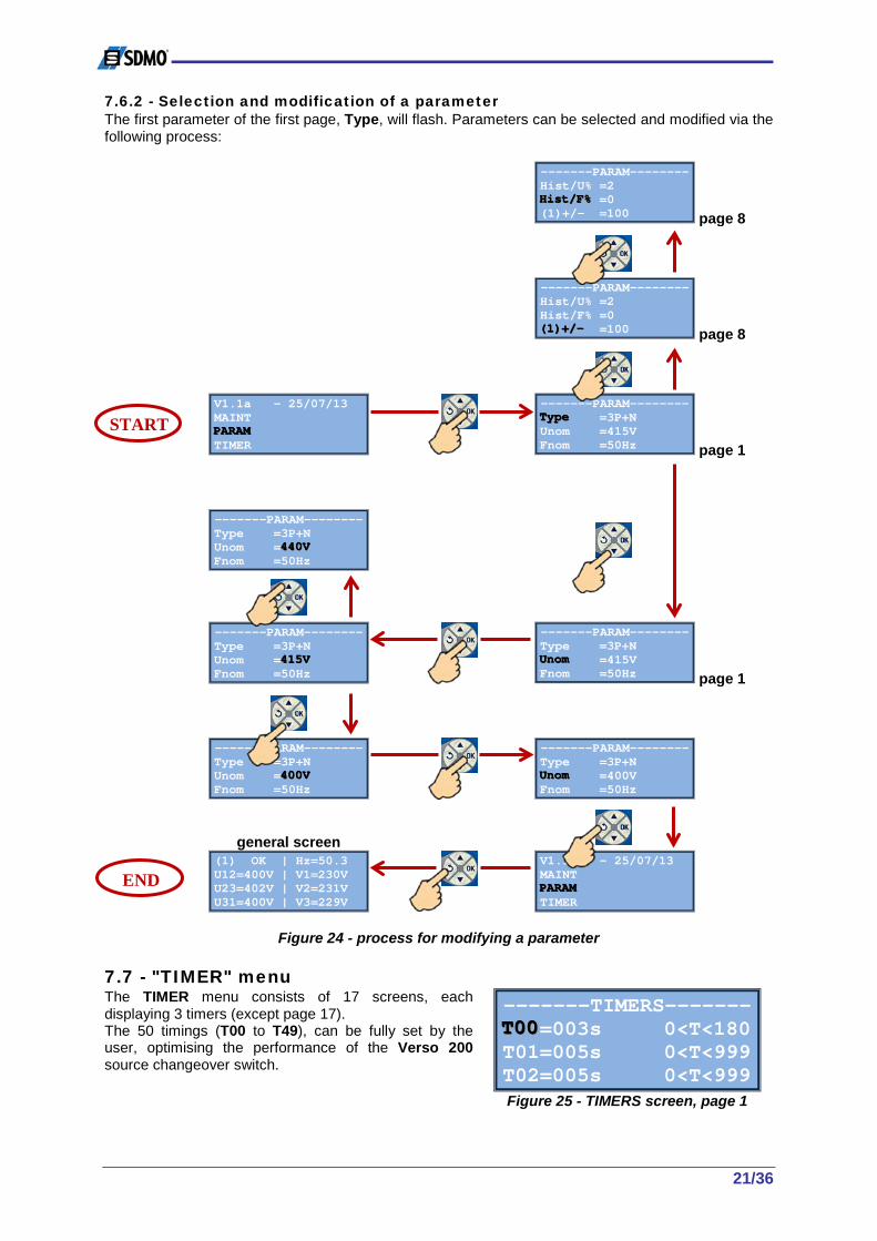
7.6.2 - Selection and modification of a parameter The first parameter of the first page, Type, will flash. Parameters can be selected and modified via the following process:
-------PARAM-------- Hist/U% =2 HHHiiisssttt///FFF%%% =0 (1)+/- =100
page 8
-------PARAM-------- Hist/U% =2 Hist/F% =0 (((111)))+++///--- =100
page 8
V1.1a - 25/07/13 MAINT PPPAAARRRAAAMMM TIMER
-------PARAM-------- TTTyyypppeee =3P+N Unom =415V Fnom =50Hz
page 1
-------PARAM-------- Type =3P+N Unom =444444000VVV Fnom =50Hz
-------PARAM-------- Type =3P+N Unom =444111555VVV Fnom =50Hz
-------PARAM-------- Type =3P+N UUUnnnooommm =415V Fnom =50Hz
page 1
-------PARAM-------- Type =3P+N Unom =444000000VVV Fnom =50Hz
-------PARAM-------- Type =3P+N UUUnnnooommm =400V Fnom =50Hz
general screen
(1)=4OK | Hz=50.3 U12=400V | V1=230V U23=402V | V2=231V U31=400V | V3=229V
V1.1a - 25/07/13 MAINT PPPAAARRRAAAMMM TIMER
Figure 24 - process for modifying a parameter
7.7 - "TIMER" menu The TIMER menu consists of 17 screens, each displaying 3 timers (except page 17). The 50 timings (T00 to T49), can be fully set by the user, optimising the performance of the Verso 200 source changeover switch.
-------TIMERS------- TTT000000=003s 0<T<180 T01=005s 0<T<999 T02=005s 0<T<999
Figure 25 - TIMERS screen, page 1
START
END

22/36
7.7.1 - List of timers The table below sets out the 50 timers available for viewing and adjustment via the TIMER menu.
No. Meaning Possible values By default T00 Loss of voltage source 1 From 0 to 180 seconds 3 seconds T01 Return of voltage source 1 From 0 to 999 seconds 5 seconds page 1 T02 Min. voltage fault source 1 From 0 to 999 seconds 5 seconds T03 Max. voltage fault source 1 From 0 to 999 seconds 5 seconds T04 Min. voltage fault source 2 From 0 to 999 seconds 5 seconds page 2 T05 Max. voltage fault source 2 From 0 to 999 seconds 5 seconds T06 Min. frequency fault source 1 From 0 to 999 seconds 5 seconds T07 Max. frequency fault source 1 From 0 to 999 seconds 5 seconds page 3 T08 Min. frequency fault source 2 From 0 to 999 seconds 5 seconds T09 Max. frequency fault source 2 From 0 to 999 seconds 5 seconds T10 Source 1 control fault From 2 to 999 seconds 5 seconds page 4 T11 Source 2 control fault From 2 to 999 seconds 5 seconds T12 Switch of source From 0 to 999 seconds/10 10/10 seconds T13 Stabilisation of voltage source 1 From 0 to 999 seconds/10 10/10 seconds page 5 T14 Stabilisation of voltage source 2 From 0 to 999 seconds/10 30/10 seconds T15 Establishment of voltage source 1 From 0 to 999 seconds/10 5/10 seconds T16 Establishment of voltage source 2 From 0 to 999 seconds/10 5/10 seconds page 6 T17 GS cooling source 1 From 0 to 999 seconds 60 seconds T18 GS cooling source 2 From 0 to 999 seconds 60 seconds T19 Test mode in progress From 0 to 999 seconds 600 seconds page 7 T20 EJP notice (for France only) From 0 to 999 minutes 20 minutes T21 EJP loss (For France only) From 0 to 999 seconds 600 seconds T22 Power cut-off From 0 to 999 seconds 10 seconds page 8 T23 Failure to start From 0 to 999 seconds 30 seconds T24 Reserved for future development From 0 to 999 seconds 120 seconds T25 Reserved for future development From 0 to 999 seconds 120 seconds page 9 T26 Scrolling down of measurement screens From 1 to 10 seconds 5 seconds T27 Reserved for future development From 0 to 999 seconds 3 seconds T28 Critical min. voltage fault source 1 From 0 to 999 seconds 1 second page 10 T29 Critical max. voltage fault source 1 From 0 to 999 seconds 1 second T30 Critical min. voltage fault source 2 From 0 to 999 seconds 5 seconds T31 Critical min. voltage fault source 2 From 0 to 999 seconds 5 seconds page 11 T32 Critical min. frequency fault source 1 From 0 to 999 seconds 1 second T33 Critical max. frequency fault source 1 From 0 to 999 seconds 1 second T34 Critical min. frequency fault source 2 From 0 to 999 seconds 5 seconds page 12 T35 Critical max. frequency fault source 2 From 0 to 999 seconds 5 seconds T36 Final fault source 1 From 0 to 999 seconds/10 5/10 seconds T37 Reserved for future development From 0 to 999 seconds 1 second page 13 T38 Final fault source 2 From 0 to 999 seconds/10 5/10 seconds T39 Reserved for future development From 0 to 999 seconds 1 second T40 Production request From 0 to 999 seconds 10 seconds page 14 T41 Switch in changeover switch power supply From 0 to 999 seconds 3 seconds T42 Back-light activation From 0 to 999 seconds 15 seconds T43 Reserved for future development From 0 to 999 seconds 5 seconds page 15 T44 Reserved for future development From 0 to 999 seconds 5 seconds T45 Reserved for future development From 0 to 999 seconds 3 seconds T46 Reserved for future development From 0 to 999 seconds 3 seconds page 16 T47 Reserved for future development From 0 to 999 seconds 3 seconds T48 Reserved for future development From 0 to 999 seconds 3 seconds T49 Reserved for future development From 0 to 999 seconds 3 seconds page 17

23/36
7.7.2 - Selection and adjustment of a timer The first timer of page 1, T00, will flash. Timers can be selected and adjusted via the following process:
-------TIMERS------- TTT444888=003s 0<T<999 T49=003s 0<T<999
-------TIMERS------- T48=003s 0<T<999 TTT444999=003s 0<T<999
V1.1a - 25/07/13 MAINT PARAM TTTIIIMMMEEERRR
-------TIMERS------- TTT000000=003s 0<T<180 T01=005s 0<T<999 T02=005s 0<T<999
-------TIMERS------- T00=003s 0<T<180 T01=005s 0<T<999 T02=000000666sss 0<T<999
-------TIMERS------- T00=003s 0<T<180 TTT000111=005s 0<T<999 T02=005s 0<T<999
-------TIMERS------- T00=003s 0<T<180 T01=005s 0<T<999 T02=000000555sss 0<T<999
-------TIMERS------- T00=003s 0<T<180 T01=005s 0<T<999 TTT000222=005s 0<T<999
-------TIMERS------- T00=003s 0<T<180 T01=005s 0<T<999 T02=000000444sss 0<T<999
-------TIMERS------- T00=003s 0<T<180 T01=005s 0<T<999 TTT000222=004s 0<T<999
general screen
(1)=4OK | Hz=50.3 U12=400V | V1=230V U23=402V | V2=231V U31=400V | V3=229V
V1.1a - 25/07/13 MAINT PARAM TTTIIIMMMEEERRR
Figure 26 - process for adjusting a timer
START
Increase by 1
Decrease by 1
END

24/36
7.8 - "PROGRAMS" menu The PROGRAMS menu consists of several screens used to manage 3 Verso 200 source changeover switch test programs. These 3 programs use 4 different criteria to define the test.
------PROGRAMS------ PPPrrrooogggrrraaammm111 Program2 Program3
Figure 27 - PROGRAMS menu
7.8.1 - Description of criteria The following criteria define the conditions in which the changeover switch operating program will run.
Criteria Choice Description Period Off No programming
Week Generating set start-up on a very specific date. The corresponding date will be repeated every week of the year. Generating set shut-down is also possible. The date for this must be no more than 6 days after the start-up date.
Day Generating set start-up every day of the week, repeated every week of the year. 1Day Generating set start-up on a single date in the current year. There will be no start-
up the following year. Test =0KW The generating set starts up, but the changeover switch remains in the I position
(source 1). The test will stop according to the last 2 criteria. >0KW The generating set starts up, and the changeover switch shifts from the I position
to the II position. The test will stop according to the last 2 criteria. The changeover switch will shift back from the II position to the I position.
StartDate dd/mm ()
This allows the user to programme the start-up date for the generating set. This date will be systematically associated with a start-up time (Start Hour).
StopDate dd/mm This allows the user to programme the stop date for the generating set. This date will be systematically associated with a stop time (Stop Hour).
StartHour 00h 00mn ()
This allows the user to programme the start-up time for the generating set.
StopHour 00h 00mn This allows the user to programme the stop time for the generating set. () date format: day/month () time format: 00-23 hours and 00-59 minutes 7.8.2 - Selecting and modifying a program When the PROGRAMS screen appears, "Program1" will be flashing. A program can be selected for configuration cyclically using the and buttons. Press OK to select one of the 3 programs to configure, for example program 1 "Program1". The 2 first criterion then appear: Period (criterion 1) and Test (criterion 2).
------PROGRAMS------ Program1 Period=OOOffffff Test =0KW
By default, the "Period" criterion will be set to "Off" (flashing). Press or to select an option for criterion 1 (Week, Day or 1Day). Press OK to confirm. The option =0KW or >0KW will then flash. Press or to select an option for criterion 2 (=0kW or >0kW). Press OK to confirm.
------PROGRAMS------ Program1 Period=Week Test ===000KKKWWW
25/36
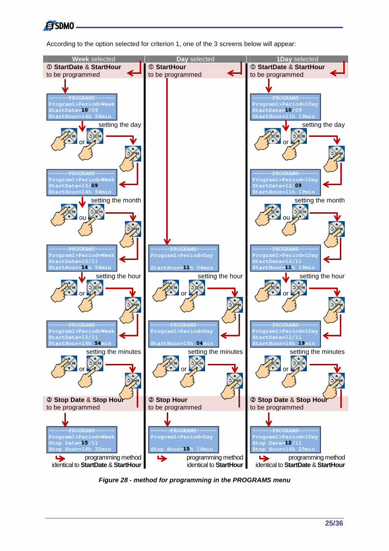
According to the option selected for criterion 1, one of the 3 screens below will appear:
Week selected Day selected 1Day selected StartDate & StartHour to be programmed
StartHour to be programmed
StartDate & StartHour to be programmed
------PROGRAMS------ Program1>Period=Week StartDate=111000/09 StartHour=14h 54min
------PROGRAMS------ Program1>Period=1Day StartDate=111000/09 StartHour=11h 19min
setting the day setting the day
or
or
------PROGRAMS------ Program1>Period=Week StartDate=15/000999 StartHour=14h 54min
------PROGRAMS------ Program1>Period=1Day StartDate=12/000999 StartHour=11h 19min
setting the month setting the month
ou
ou
------PROGRAMS------ Program1>Period=Week StartDate=15/11 StartHour=111444h 54min
------PROGRAMS------ Program1>Period=Day StartHour=111111h 04min
------PROGRAMS------ Program1>Period=1Day StartDate=12/11 StartHour=111111h 19min
setting the hour setting the hour setting the hour
or or or
------PROGRAMS------ Program1>Period=Week StartDate=15/11 StartHour=16h 555444min
------PROGRAMS------ Program1>Period=Day StartHour=15h 000444min
------PROGRAMS------ Program1>Period=1Day StartDate=12/11 StartHour=16h 111999min
setting the minutes setting the minutes setting the minutes
or or or
Stop Date & Stop Hour to be programmed
Stop Hour to be programmed
Stop Date & Stop Hour to be programmed
------PROGRAMS------ Program1>Period=Week Stop Date=111555/11 Stop Hour=16h 32min
------PROGRAMS------ Program1>Period=Day Stop Hour=111555h 16min
------PROGRAMS------ Program1>Period=1Day Stop Date=111222/11 Stop Hour=16h 25min
programming method identical to StartDate & StartHour
programming method identical to StartHour
programming method identical to StartDate & StartHour
Figure 28 - method for programming in the PROGRAMS menu

26/36
7.9 - "I/O" menu The I/O menu consists of 2 screens and 5 possible settings. This menu is used to set the parameters for the 3 inputs and 2 outputs provided on the electronic card.
----Input/Output---- IIINNN ###111=F02 (2) >0KW IN #2=F04 (1) OK? IN #3=F08 Lamp test
Figure 29 - I/O menu, page 1
The inputs are labelled IN#1, IN#2 and IN#3, and the outputs are labelled OUT#1 and OUT#2. 7.9.1 - Functions linked to inputs and outputs The inputs and outputs are linked to pre-determined functions (F00 to F09 for the inputs and F00 to F12 for the outputs). According to the user's needs, two inputs or the two outputs can be programmed for the same function (e.g.: IN#1=F04, IN#2=F04). All available functions are described in the table below. The title of each function is displayed on the screen for each function number (see previous screen-shot). Functions available for inputs Number Title Description
F00 No associated function F01 PreavisEJP EJP notice (for France only) () F02 Top EJP Top EJP (for France only) () F03 Prior EJP EJP priority (for France only) () F04 (2) >0KW Source 2 production request F05 (2) >0KW+T Source 2 production request associated with a timer F06 (1) OK? Confirmation of return of voltage source 1 F07 1->(0)<-2 Changeover switch forced into O position F08 Lamp test Lamp test over distance F09 SOS 4F01 Surge arrester fault report (optional fitting to the changeover switch)
Functions available for outputs Number Title Description
F00 No associated function F01 ->(1) Report changeover switch closed in I position F02 ->(2) Report changeover switch closed in II position F03 (1)-> Report changeover switch open over source 1 F04 (2)-> Report changeover switch open over source 2 F05 (1) OK Source 1 OK in performance range F06 (2) OK Source 2 OK in performance range F07 AUTO NOK Verso 200 not in AUTO mode F08 (2) + T22 Power interruption request F09 EJP EJP mode report () F10 IN#1 Input 1 report F11 IN#2 Input 2 report F12 IN#3 Input 3 report
() EJP: this is a concept specific to France and means: Effacement Jours de Pointe (peak-day load reduction) The default setting for the 3 inputs and 2 outputs is F00 (no associated function).

27/36
7.9.2 - Selecting and programming an input or output When the I/O menu appears, the first parameter, IN #1, will flash. An input or output can be selected via the following process.
----Input/Output---- OOOUUUTTT###111=F05 (1) OK OUT#2=F06 (2) OK
----Input/Output---- OUT#1=F05 (1) OK OOOUUUTTT###222=F06 (2) OK
V1.1a - 25/07/13 PROGRAM III///OOO AUTOSET
----Input/Output---- IIINNN ###111=F02 (2) >0KW IN #2=F04 (1) OK? IN #3=F08 Lamp test
----Input/Output---- IN #1=F02 (2) >0KW IN #2=F04 (1) OK? IN #3=FFF000999 SOS 4F01
----Input/Output---- IN #1=F04 (2) >0KW IIINNN ###222=F06 (1) OK? IN #3=F08 Lamp test
----Input/Output---- IN #1=F04 (2) >0KW IN #2=F06 (1) OK? IN #3=FFF000888 Lamp test
----Input/Output---- IN #1=F04 (2) >0KW IN #2=F06 (1) OK? IIINNN ###333=F08 Lamp test
----Input/Output---- IN #1=F04 (2) >0KW IN #2=F06 (1) OK? IN #3=FFF000777 1->(0)<-2
----Input/Output---- IN #1=F04 (2) >0KW IN #2=F06 (1) OK? IIINNN ###333=F07 1->(0)<-2
general screen
(1)=4OK | Hz=50.3 U12=400V | V1=230V U23=402V | V2=231V U31=400V | V3=229V
V1.1a - 25/07/13 PROGRAM III///OOO AUTOSET
Figure 30 - process for programming an input or output
7.10 - "AUTOSET" menu The AUTOSET menu consists of one screen. This menu is used to run a new auto-configuration after the first operation. Mains power must be supplied over source 1 in order to run this operation.
------AUTOSET------- AUTOSET =OK
Figure 31 - AUTOSET screen
START
Function F09 flashing
Function F07 flashing
END
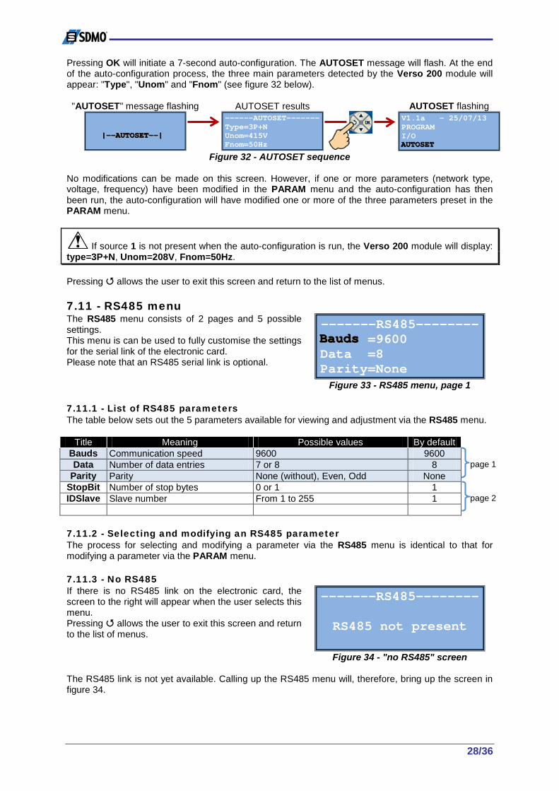
28/36
Pressing OK will initiate a 7-second auto-configuration. The AUTOSET message will flash. At the end of the auto-configuration process, the three main parameters detected by the Verso 200 module will appear: "Type", "Unom" and "Fnom" (see figure 32 below). "AUTOSET" message flashing
|||------AAAUUUTTTOOOSSSEEETTT------|||
AUTOSET results
------AUTOSET------- Type=3P+N Unom=415V Fnom=50Hz
AUTOSET flashing
V1.1a - 25/07/13 PROGRAM I/O AAAUUUTTTOOOSSSEEETTT
Figure 32 - AUTOSET sequence No modifications can be made on this screen. However, if one or more parameters (network type, voltage, frequency) have been modified in the PARAM menu and the auto-configuration has then been run, the auto-configuration will have modified one or more of the three parameters preset in the PARAM menu.
If source 1 is not present when the auto-configuration is run, the Verso 200 module will display: type=3P+N, Unom=208V, Fnom=50Hz. Pressing allows the user to exit this screen and return to the list of menus. 7.11 - RS485 menu The RS485 menu consists of 2 pages and 5 possible settings. This menu is can be used to fully customise the settings for the serial link of the electronic card. Please note that an RS485 serial link is optional.
-------RS485-------- BBBaaauuudddsss =9600 Data =8 Parity=None
Figure 33 - RS485 menu, page 1 7.11.1 - List of RS485 parameters The table below sets out the 5 parameters available for viewing and adjustment via the RS485 menu.
Title Meaning Possible values By default Bauds Communication speed 9600 9600 Data Number of data entries 7 or 8 8 page 1
Parity Parity None (without), Even, Odd None StopBit Number of stop bytes 0 or 1 1 IDSlave Slave number From 1 to 255 1 page 2
7.11.2 - Selecting and modifying an RS485 parameter The process for selecting and modifying a parameter via the RS485 menu is identical to that for modifying a parameter via the PARAM menu. 7.11.3 - No RS485 If there is no RS485 link on the electronic card, the screen to the right will appear when the user selects this menu. Pressing allows the user to exit this screen and return to the list of menus.
-------RS485-------- RS485 not present
Figure 34 - "no RS485" screen
The RS485 link is not yet available. Calling up the RS485 menu will, therefore, bring up the screen in figure 34.

29/36
7.12 - "INIT" menu The INIT menu consists of one screen. This menu can be used to initiate the system. The system must be initiated with voltage supply from source 1. The OK command will appear on the screen.
--------INIT-------- INIT PARAM =OK
Figure 35 - INIT screen
After pressing OK, initialisation is launched and the following actions are run:
1- Return to the default values for the PARAM menu parameters; 2- Automatic network-, voltage- and frequency-type test; 3- Return to the default values for the TIMER menu timers; 4- The 3 inputs and 2 outputs are set to F00; 5- The events stack is reset in the EVENTS menu.
IMPORTANT: if there is no voltage supply from source 1 when initiating the system, there will be no automatic test (point 2 above) and the following default settings will be configured: - source 1 configured as 3P+N (default parameter); - voltage configured as 208V (lowest possible value) (default parameter = 415V); - frequency configured as 50Hz (default parameter). The initialisation lasts around 10 seconds and proceeds as follows:
"INIT" message flashing
|||---------IIINNNIIITTT---------|||
"INIT" message fixed
|---INIT---|
INIT flashing in the list of menus
V1.1a - 25/07/13 RS485 IIINNNIIITTT FACTORY
Figure 36 - initialisation sequence 7.13 - "FACTORY" menu The FACTORY menu consists of 2 screens and 5 accessible data entries. Each data entry appears on an additional screen for a specific function. The five screens are described below.
-------FACTORY------ IIIDDD CLOCK USB
Figure 37 - FACTORY menu 7.13.1 - List of screens under the FACTORY menu The table below sets out the screens that can be accessed from the FACTORY menu.
Title Meaning ID Provides information on the electronic card
CLOCK Allows the date and time to be updated page 1 USB Allows data files to be recovered or transferred SPY Reserved for troubleshooting by SDMO Industries
AUTOCONF Adjustment of parameters page 2
7.13.2 - ID screen The ID screen provides information on the Verso 200 electronic card: - hardware identification (electronic card); - software identification; - the Verso 200 module serial number.
---------ID--------- S/N =1100254 Version=1.1.00 S/N HW =524Z1
Figure 38 - ID menu

30/36
This information cannot be adjusted. It also appears in the "S/N.txt" file, which is created when a USB key is inserted (see section 7.13.4). Pressing the button exits this screen. 7.13.3 - "CLOCK" screen The "CLOCK" screen can be used to set the time and date which will then be used for recording the time and date of events (conditions, alarms and faults). When the menu is brought up, HOURS will flash.
-------CLOCK-------- HHHOOOUUURRRSSS =11h 24min 46s DATE =dd/mm/yy =25/07/13
Figure 39 - CLOCK menu Process for setting the time: Starting from the screen above, press OK to access the time. Press or to adjust the hour (format: 00-23), then press OK to confirm. Press or to adjust the minutes (format: 00-59), then press OK to confirm. Press or to adjust the seconds (format: 00-59), then press OK to confirm. HOURS will flash again. Process for setting the date: Starting from the previous screen, press to access the DATE. DATE will flash. Press OK to access the date. Press or to adjust the day (format: 01-31), then press OK to confirm. Press or to adjust the month (format: 01-12), then press OK to confirm. Press or to adjust the year (format: 12-99), then press OK to confirm. HOURS will flash again. Press to exit the screen. NB: when a data category is flashing (hours, minutes, seconds, day, month, year), pressing has no effect. 7.13.4 - "USB" screen Insert a USB key into the port in the electronic card. If the key is recognised by the system, the screen to the right can then be accessed through the FACTORY menu, by selecting USB. The line displaying ATS-->USB=INFO will be flashing.
--------USB--------- AAATTTSSS------>>>UUUSSSBBB===IIINNNFFFOOO ATS-->USB=PARAM USB-->ATS=PROG
Figure 40 - USB menu 3 options are available on this screen: ATS-->USB=INFO Automatic creation of a txt file (S/N.txt) and transfer of the following data from
the electronic card to the USB key: The full PARAM, TIMER, ID and EVENTS menus ATS-->USB=PARAM Automatic creation of a txt file (PARAM.txt) and transfer of the following data
from the electronic card to the USB key: the full PARAM and TIMER menus USB-->ATS=PROG This allows the transfer of data from the PARAM.txt file on the USB key to the
electronic card: The full PARAM menu Select the desired option using the and buttons, then press OK to run the operation. Once the operation has been completed, the first line, ATS-->USB=INFO, will flash again regardless of the option that was selected. The USB key can then be removed. Press the button to exit the USB menu.

31/36
If the USB key is not connected to the electronic card, the screen to the right will appear when the USB menu is brought up.
--------USB--------- key not detected
Figure 41 - USB not detected 7.13.5 - "SPY" screen The SPY screen is for the internal use of SDMO Industries. It gives a full overview of the condition of the source changeover switch (LEDs, switch positions, inputs, outputs, etc.). It allows the troubleshooting of the inputs and outputs of the electronic card.
---------SPY-------- 0000000001000011 1001000
Figure 42 - SPY screen Pressing the button exits the SPY screen and returns to the list of accessible screens in FACTORY. 7.13.6 - "AUTOCONF" screen The AUTOCONF screen allows an auto-configuration to be run when the source changeover switch goes back to receiving voltage from source 1. On the screen to the right, AUTOCONF will be flashing. Press OK, "0" will flash.
------AUTOCONF------ AAAUUUTTTOOOCCCOOONNNFFF=0
Figure 43 - AUTOCONF screen Change the AUTOCONF value by pressing or . The AUTOCONF value will change to "1". Press OK to confirm this choice. The next time the changeover switch has its power supply cut and then return, or when it is next initiated (INIT menu), an automatic configuration will be run. The flowchart below details the automatic sequence that runs once AUTOCONF=1 has been selected and an initialisation has been run (section 7.12):
|||---------IIINNNIIITTT---------|||
|||------AAAUUUTTTOOOCCCOOONNNFFF------|||
V1.1a - 25/07/13 Type=333PPP | Unom=400V | OK?=OK Fnom=50Hz |
Figure 44 - INIT and AUTOCONF sequence

32/36
8 - Automatic responses and safety features 8.1 - Voltage detection The table below sets out the voltage ranges that allow the system to detect the nominal voltage value Unom during auto-configuration. Nominal voltage detection ranges
Nominal voltage Min voltage Max voltage Min deviation Max deviation 208V 214V 6V 220V 215V 227V -5V 7V 230V 228V 237V -2V 7V 240V 238V -2V 380V 390V 10V 400V 391V 407V -9V 7V 415V 408V 427V -7V 12V 440V 428V -12V
Table 8 - voltage detection ranges How to use the table: If the voltage at the terminals of the changeover switch, when supplied by source 1, is between 408 Volts and 427 Volts, the system will display a nominal voltage of 415 Volts on the screen. Nevertheless, it is the user's responsibility to check the value given by the system, as it may have been incorrect at the time of measurement. 8.2 - Phase sequence The electronic module is equipped with a system to detect the order of source 1 (mains) and source 2 (generating set) phases. The three phases of a three-phase network create a rotating field following the sketch below. . The rotating field is "direct" when the three phases rotate clockwise. . The rotating field is "reverse" when the three phases rotate anticlockwise. In the case of a reverse field, it is necessary to modify the wiring of the source changeover switch.
8.3 - Loss of voltage source 1 There is considered to be a "loss of voltage" over source 1 when the mains voltage U upstream of the source changeover switch is equal to or below Unom/2. When voltage is detected to be at this level, the power outage timer (T00) is activated. If, at the end of this timer, the voltage has not returned to a correct level, the power cut will then be taken into account. The changeover switch will remain in the I position. A starting order will be sent to the generating set. Following the generating set start-up and when the voltage has stabilised (T14), supply is returned to the source switching mechanism and the changeover switch changes to the O position, and then to the II position. Supply is then returned. 8.4 - Return of voltage source 1 There is considered to be a "return of voltage" over source 1 when the mains voltage U upstream of the source changeover switch is greater than Unom/2. When voltage is detected to be at this level, the mains return timer (T01) is activated. If, at the end of the timer, voltage has not fallen back below Unom/2, the return of voltage is confirmed, timer T18 is started and there will be a switch from source 2 to source 1. At the end of the T18 timer, the generating set automatically receives a stop order (remote deactivation order). 8.5 - Alarms and faults associated with frequency and voltage This section explains how to acknowledge and manage the alarms and faults associated with variations in frequency and voltage over the two voltage sources.
direction of phases rotation
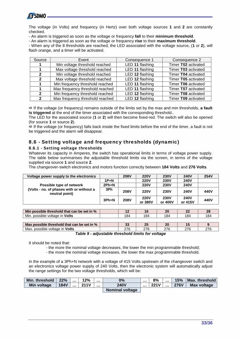
33/36
The voltage (in Volts) and frequency (in Hertz) over both voltage sources 1 and 2 are constantly checked. - An alarm is triggered as soon as the voltage or frequency fall to their minimum threshold. - An alarm is triggered as soon as the voltage or frequency rise to their maximum threshold. - When any of the 8 thresholds are reached, the LED associated with the voltage source, (1 or 2), will flash orange, and a timer will be activated.
Source Event Consequence 1 Consequence 2 1 Min voltage threshold reached LED 11 flashing Timer T02 activated 1 Max voltage threshold reached LED 11 flashing Timer T03 activated 2 Min voltage threshold reached LED 12 flashing Timer T04 activated 2 Max voltage threshold reached LED 12 flashing Timer T05 activated 1 Min frequency threshold reached LED 11 flashing Timer T06 activated 1 Max frequency threshold reached LED 11 flashing Timer T07 activated 2 Min frequency threshold reached LED 12 flashing Timer T08 activated 2 Max frequency threshold reached LED 12 flashing Timer T09 activated
If the voltage (or frequency) remains outside of the limits set by the max and min thresholds, a fault is triggered at the end of the timer associated with the corresponding threshold.. The LED for the associated source (1 or 2) will then become fixed-red. The switch will also be opened (for source 1 or source 2). If the voltage (or frequency) falls back inside the fixed limits before the end of the timer, a fault is not be triggered and the alarm will disappear. 8.6 - Setting voltage and frequency thresholds (dynamic) 8.6.1 - Setting voltage thresholds Whatever its capacity in Amperes, the switch has operational limits in terms of voltage power supply. The table below summarises the adjustable threshold limits via the screen, in terms of the voltage supplied via source 1 and source 2. The changeover-switch electronics and motors function correctly between 184 Volts and 276 Volts.
Voltage power supply to the electronics 208V 220V 230V 240V 254V 1P+N 220V 230V 240V
Possible type of network 2Ph+N 220V 230V 240V (Volts - no. of phases with or without a
neutral point) 3Ph 208V 220V 230V 240V 440V
3Ph+N 208V 220V or 380V
230V or 400V
240V or 415V 440V
Min possible threshold that can be set in % 12 16 20 22 28 Min. possible voltage in Volts 184 184 184 184 184 Max possible threshold that can be set in % 33 25 20 15 9 Max. possible voltage in Volts 276 276 276 276 276
Table 9 - adjustable threshold limits for voltage It should be noted that: - the more the nominal voltage decreases, the lower the min programmable threshold; - the more the nominal voltage increases, the lower the max programmable threshold. In the example of a 3Ph+N network with a voltage of 415 Volts upstream of the changeover switch and an electronics voltage power supply of 240 Volts, then the electronic system will automatically adjust the range settings for the two voltage thresholds, which will be:
Min. threshold 22% … 12% … 0% … 8% … 15% Max. threshold Min voltage 184V … 211V … 240V … 221V … 276V Max voltage
Nominal voltage

34/36
8.6.2 - Setting frequency thresholds Whatever its capacity in Amperes, the source changeover switch has operational limits in terms of frequency. The table below summarises the adjustable threshold limits via the screen, in terms of the frequency of the voltage supplied via source 1 and source 2. The changeover-switch electronics and motors function correctly between 45 Volts and 65 Volts.
Frequency of the voltage power supply to the electronics 50Hz 60Hz 1P+N 1P+N 2P+N 2P+N
Possible type of network 3P 3P 3P+N 3P+N
Min possible threshold in % 10 25
Min. possible frequency in Hertz 45 45
Max possible threshold in % 30 8 Max. possible frequency in Hertz 65 65
Table 10 - adjustable threshold limits for frequency In the example of a frequency of 50Hz over the voltage power supply upstream of the source changeover switch, the electronic system will automatically adjust the range setting of the two frequency thresholds, which will be:
Min. threshold 10% … 6% … 0% … 12% … 30% Max. threshold Min frequency 45Hz … 47Hz … 50Hz … 56Hz … 65Hz Max frequency
Nominal frequency 8.7 - Critical and final voltage thresholds As well as the min. and max. thresholds that can be adjusted in relation to the voltage power supply, 4 additional thresholds are in place in order to ensure optimum protection of the electronics. 8.7.1 - Critical thresholds The critical thresholds are the min. and max. operational voltages issued by the appliance manufacturer:
- Min. critical threshold = 184 Volts; - Max. critical threshold = 276 Volts.
If the voltage reaches one of the 2 critical thresholds, a timer is activated (see table of timers in section 7.7.1). If, at the end of this timer, the voltage has not fallen back below the critical threshold, the electronic system automatically turns the switch to the opposite position. 8.7.2 - Final thresholds The final thresholds are the voltages that must not be exceeded, beyond the critical thresholds:
- Min. final threshold = 150 Volts; - Max. final threshold = 300 Volts.
If, while the critical threshold timer is active, the voltage reaches any of the 2 final thresholds, a new, very short timer (usually 0.5 seconds) will be activated. At the end of this timer, the electronic system automatically turns the switch to the opposite position. 8.8 - Critical frequency thresholds As well as the min. and max. thresholds that can be adjusted in relation to the frequency of the voltage power supply, 2 additional thresholds are in place in order to ensure optimum protection of the electronics of the unit. The critical thresholds are the min. and max. operational frequencies issued by the appliance manufacturer:
- Min. critical threshold = 45Hz; - Max. critical threshold = 65Hz.

35/36
If the voltage reaches one of the 2 critical thresholds, a timer is activated (see table of timers in section 7.7.1). If, at the end of this timer, the frequency has not fallen back below the critical threshold, the electronic system automatically turns the switch to the opposite position. 8.9 - "EJP" function (for France only) The "EJP" function can be used for the French market. "EJP," standing for peak-day load reduction, is a pricing system and a way of operating employed by electricity providers in France. The user enjoys a low rate over a period of 343 days per year. In exchange, the price of a kWh is at a premium for the remaining 22 days. These days are called "EJP days" and are distributed between 1 November and 31 March. The user is warned the day before each EJP-rate day ("EJP-12 hours" contact available). Another "EJP-30 minutes" contact (again called "EJP notice") closes automatically 30 minutes before the start of the EJP. A T20 timer (generally 20 minutes) is initiated, and at the end of this timer the generating set starts up automatically. When the "top EJP" contact is closed 30 minutes after the EJP notice, the switch turns to the "I" position, to the "O" position and then to the "II" position. The "top EJP" contact remains closed from 6am to 10pm. At 10pm, the contact opens, the switch returns to the I position, and the generating set begins a cool-down and then stops at the end of the T18 timer. The EJP function is included with the Verso 200, but it is not programmed (see paragraph 7.9.1). 8.10 - Effect of temperature The changeover switch is designed to operate inside housing (unit or cabinet) at 40°C. If the temperature surrounding the switch exceeds 40°C, the user should refer to the table below in order to determine the switch capacity applicable in relation to its intended use (load) and the temperature.
Temp. Capacity in Amperes Up to 40°C 200 250 400 630 800 1000 1250 1600 2000 2500 3200
Currents with downgrade (in Amperes) From 41°C to 50°C 180 225 360 567 720 900 1125 1440 1800 2250 2880 From 51°C to 60°C 144 180 288 454 576 720 900 1152 1440 1800 2304 From 61°C to 70°C 101 126 202 318 404 504 630 807 1008 1260 1613
Table 11 - temperature downgrades Temp. is the surrounding air temperature of the appliance. It should be noted that using the source changeover switch in a surrounding air temperature of over 60°C reduces the switch performance by half. Extreme care must, therefore, be taken, with regard to the ambient temperature inside the unit.
9 - Options The table below sets out the options available for the Verso 200 source changeover switch.
1 IT set-up with neutral point (ITAN)
Replacement of the 4F17 fuse with a 3P+N circuit breaker
2 IT set-up without neutral point (ITSN) For Unom ≤ 240V
Replacement of the 4F17 fuse with a 3P circuit breaker
3 IT set-up without neutral point (ITSN) For Unom ≥ 240V
Same as option no. 2, with the addition of a three-phase kit without neutral point (auto-transformer)
4 Three-phase network without neutral from 380V to 440V
Addition of a three-phase kit without neutral (auto-transformer)
5 70kA surge arrester Addition of a surge arrester kit, only for size 1 equipment, delivered with installation notice
6 wiring through the top Impossible after delivery, must be pre-ordered 7 IP55 protection rating For size 1 unit only 8 Base Height 200mm for all equipment sizes

36/36
Personal Notes …………………………………………………………………………………………………………………………………………………………………………………………………………………………………………………………………………………………………………………………………………………………………………………………………………………………………………………………………………………………………………………………………………………………………………………………………………………………………………………………………………………………………………………………………………………………………………………………………………………………………………………………………………………………………………………………………………………………………………………………………………………………………………………………………………………………………………………………………………………………………………………………………………………………………………………………………………………………………………………………………………………………………………………………………………………………………………………………………………………………………………………………………………………………………………………………………………………………………………………………………………………………………………………………………………………………………………………………………………………………………………………………………………………………………………………………………………………………………………………………………………………………………………………………………………………………………………………………………………………………………………………………………………………………………………………………………………………………………………………………………………………………………………………………………………………………………………………………………………………………………………………………………………………………………………………………………………………………………………………………………………………………………………………………………………………………………………………………………………………………………………………………………………………………………………………………………………………………………………………………………………………………………………………………………………………………………………………………………………………………………………………………………………………………………………………………………………………………………………………………………………………………………………………………………………………………………………………………………………………………………………………………………………………………………………………………………………………………………………………………………………………………………………………………………………………………………………………………………………………………………………………………………………………………………………………………………………………………………………………………………………………………………………………………………………………………………………………………………………………………………………………………………………………………………………………………………………………………………………………………………………………………………………………………………………………………………………………………………………………………………………………………………………………………………………………………………………………………………………………………………………………………………………………………………………………………………………………………………………………………………………………………………………………………………………………………………………………………………………………………………………………………………………………………………………………………………………………………………………………………………………………………………………………………………………………………………………………………………………………………………………………………………………………………………………………………………………………………………………………………………………………………………………………………………………………………………………………………………………………………………………………………………………………………………………………………………………………………………………………………………………………………………………………………………………………………………………………………………………………………………………………………………………………………………………………………………………………………………………………………………………………………………………………………………………………………………………………………………………………………………………………………………………………………………………………………………………………………………………………………………………………………………………………………………………………………………………………………………………………………………………………………………………………………………………………………………………………………………………………………………………………………………………………………………………………………………………………………………………………………………………………………………………………………………………………………………………………………………………………………………………………………………………………………………………………………………………………………………………………………………………………………………………………………………………………………………………………………………………………………......