Communities and Clustering in some Social Networks Guido Caldarelli SMC CNR-INFM Rome.

USER GUIDE
SMC2890W-AG / SMC2891W-AG
Elite Connect™802.11a/g Outdoor Enterprise Access Point

20 Mason,Irvine, CA 92618Phone: (949) 679-8000
EliteConnect™ SMC2890W-AG and SMC2891W-AG Universal 2.4GHz/5GHz Wireless Dual-Band Outdoor Access Point
The easy way to make all your network connections
February 2007Revision Number: R01 F1.0.0.1

CopyrightInformation furnished by SMC Networks, Inc. (SMC) is believed to be accurate and reliable. However, no responsibility is assumed by SMC for its use, nor for any infringements of patents or other rights of third parties which may result from its use. No license is granted by implication or otherwise under any patent or patent rights of SMC. SMC reserves the right to change specifications at any time without notice.
Copyright © 2005 bySMC Networks, Inc.
20 MasonIrvine, CA 92618
All rights reserved.
Trademarks:SMC is a registered trademark; and EliteConnect is a trademark of SMC Networks, Inc. Other product and company names are trademarks or registered trademarks of their respective holders.

Compliances
Federal Communication Commission Interference Statement
This equipment has been tested and found to comply with the limits for a Class B digital device, pursuant to Part 15 of the FCC Rules. These limits are designed to provide reasonable protection against harmful interference in a residential installation. This equipment generates, uses and can radiate radio frequency energy and, if not installed and used in accordance with the instructions, may cause harmful interference to radio communications. However, there is no guarantee that interference will not occur in a particular installation. If this equipment does cause harmful interference to radio or television reception, which can be determined by turning the equipment off and on, the user is encouraged to try to correct the interference by one of the following measures:
• Reorient or relocate the receiving antenna• Increase the separation between the equipment and receiver• Connect the equipment into an outlet on a circuit different from that to which the receiver
is connected• Consult the dealer or an experienced radio/TV technician for help
FCC Caution: Any changes or modifications not expressly approved by the party responsible for compliance could void the user’s authority to operate this equipment. This device complies with Part 15 of the FCC Rules. Operation is subject to the following two conditions: (1) This device may not cause harmful interference, and (2) this device must accept any interference received, including interference that may cause undesired operation.
IMPORTANT NOTE: FCC Radiation Exposure Statement
This equipment complies with FCC radiation exposure limits set forth for an uncontrolled environment. This equipment should be installed and operated with a minimum distance of 20 centimeters (8 inches) between the radiator and your body. This transmitter must not be co-located or operating in conjunction with any other antenna or transmitter.
Wireless 5 GHz Band Statement:
As the access point can operate in the 5150-5250 MHz frequency band it is limited by the FCC, Industry Canada and some other countries to indoor use only so as to reduce the potential for harmful interference to co-channel Mobile Satellite systems.
High power radars are allocated as primary users (meaning they have priority) of the 5250-5350 MHz and 5650-5850 MHz bands. These radars could cause interference and/or damage to the access point.
i

VCCI Notice
This is a class A product based on the standard of the Voluntary Control Council for Interference by Information Technology Equipment (VCCI). If this equipment is used in a domestic environment, radio disturbance may arise. When such trouble occurs, the user may be required to take corrective actions.
EC Conformance Declaration
Marking by the above symbol indicates compliance with the Essential Requirements of the R&TTE Directive of the European Union (1999/5/EC). This equipment meets the following conformance standards:
• EN 60950 (IEC 60950) - Product Safety• EN 301 893 - Technical requirements for 5 GHz radio equipment• EN 300 328 - Technical requirements for 2.4 GHz radio equipment• EN 301 489-1 / EN 301 489-17 - EMC requirements for radio equipment
Countries of Operation & Conditions of Use in the European Community
This device is intended to be operated in all countries of the European Community. Requirements for indoor vs. outdoor operation, license requirements and allowed channels of operation apply in some countries as described below:
Note: The user must use the configuration utility provided with this product to ensure the channels of operation are in conformance with the spectrum usage rules for European Community countries as described below.
• This device requires that the user or installer properly enter the current country of operation in the command line interface as described in the user guide, before operating this device.
• This device will automatically limit the allowable channels determined by the current country of operation. Incorrectly entering the country of operation may result in illegal operation and may cause harmful interference to other system. The user is obligated to ensure the device is operating according to the channel limitations, indoor/outdoor restrictions and license requirements for each European Community country as described in this document.
ii

• This device employs a radar detection feature required for European Community operation in the 5 GHz band. This feature is automatically enabled when the country of operation is correctly configured for any European Community country. The presence of nearby radar operation may result in temporary interruption of operation of this device. The radar detection feature will automatically restart operation on a channel free of radar.
• The 5 GHz Turbo Mode feature is not allowed for operation in any European Community country. The current setting for this feature is found in the 5 GHz 802.11a Radio Settings Window as described in the user guide.
• The 5 GHz radio's Auto Channel Select setting described in the user guide must always remain enabled to ensure that automatic 5 GHz channel selection complies with European requirements. The current setting for this feature is found in the 5 GHz 802.11a Radio Settings Window as described in the user guide.
• This device may be operated indoors or outdoors in all countries of the European Community using the 2.4 GHz band: Channels 1 - 13, except where noted below.- In Italy the end-user must apply for a license from the national spectrum authority to
operate this device outdoors. - In Belgium outdoor operation is only permitted using the 2.46 - 2.4835 GHz band:
Channel 13.- In France outdoor operation is only permitted using the 2.4 - 2.454 GHz band:
Channels 1 - 7
Operation Using 5 GHz Channels in the European Community
The user/installer must use the provided configuration utility to check the current channel of operation and make necessary configuration changes to ensure operation occurs in conformance with European National spectrum usage laws as described below and elsewhere in this document.
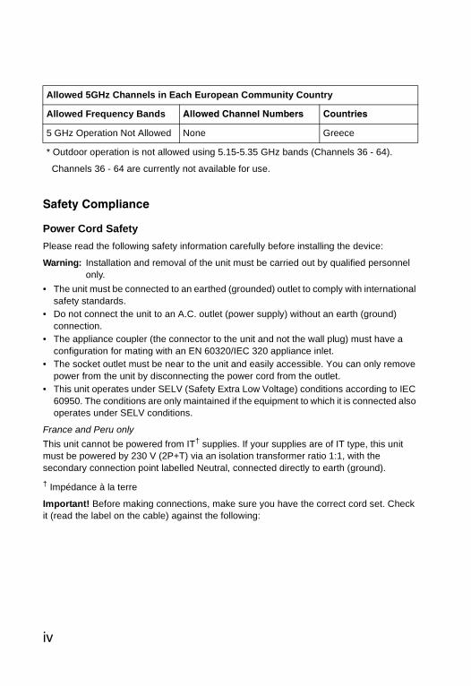
Allowed 5GHz Channels in Each European Community Country
Allowed Frequency Bands Allowed Channel Numbers Countries
5.15 - 5.25 GHz* 36, 40, 44, 48 Austria, Belgium
5.15 - 5.35 GHz* 36, 40, 44, 48, 52, 56, 60, 64 France, Switzerland, Liechtenstein
5.15 - 5.35* & 5.470 - 5.725 GHz
36, 40, 44, 48, 52, 56, 60, 64, 100, 104, 108, 112, 116, 120, 124, 128, 132, 136, 140
Denmark, Finland, Germany, Iceland, Ireland, Italy, Luxembourg, Netherlands, Norway, Portugal, Spain, Sweden, U.K.
iii
Safety Compliance
Power Cord SafetyPlease read the following safety information carefully before installing the device:
Warning: Installation and removal of the unit must be carried out by qualified personnel only.
• The unit must be connected to an earthed (grounded) outlet to comply with international safety standards.
• Do not connect the unit to an A.C. outlet (power supply) without an earth (ground) connection.
• The appliance coupler (the connector to the unit and not the wall plug) must have a configuration for mating with an EN 60320/IEC 320 appliance inlet.
• The socket outlet must be near to the unit and easily accessible. You can only remove power from the unit by disconnecting the power cord from the outlet.
• This unit operates under SELV (Safety Extra Low Voltage) conditions according to IEC 60950. The conditions are only maintained if the equipment to which it is connected also operates under SELV conditions.
France and Peru onlyThis unit cannot be powered from IT† supplies. If your supplies are of IT type, this unit must be powered by 230 V (2P+T) via an isolation transformer ratio 1:1, with the secondary connection point labelled Neutral, connected directly to earth (ground).† Impédance à la terre
Important! Before making connections, make sure you have the correct cord set. Check it (read the label on the cable) against the following:
5 GHz Operation Not Allowed None Greece
* Outdoor operation is not allowed using 5.15-5.35 GHz bands (Channels 36 - 64).
Channels 36 - 64 are currently not available for use.
Allowed 5GHz Channels in Each European Community Country
Allowed Frequency Bands Allowed Channel Numbers Countries
iv

Veuillez lire à fond l'information de la sécurité suivante avant d'installer l’appareil:
AVERTISSEMENT: L’installation et la dépose de ce groupe doivent être confiés à un personnel qualifié.
• Ne branchez pas votre appareil sur une prise secteur (alimentation électrique) lorsqu'il n'y a pas de connexion de mise à la terre (mise à la masse).
• Vous devez raccorder ce groupe à une sortie mise à la terre (mise à la masse) afin de respecter les normes internationales de sécurité.
• Le coupleur d’appareil (le connecteur du groupe et non pas la prise murale) doit respecter une configuration qui permet un branchement sur une entrée d’appareil EN 60320/IEC 320.
• La prise secteur doit se trouver à proximité de l’appareil et son accès doit être facile. Vous ne pouvez mettre l’appareil hors circuit qu’en débranchant son cordon électrique au niveau de cette prise.
Power Cord Set
U.S.A. and Canada
The cord set must be UL-approved and CSA certified.
The minimum specifications for the flexible cord are:- No. 18 AWG - not longer than 2 meters, or 16 AWG.- Type SV or SJ- 3-conductor
The cord set must have a rated current capacity of at least 10 A
The attachment plug must be an earth-grounding type with NEMA 5-15P (15 A, 125 V) or NEMA 6-15P (15 A, 250 V) configuration.
Denmark The supply plug must comply with Section 107-2-D1, Standard DK2-1a or DK2-5a.
Switzerland The supply plug must comply with SEV/ASE 1011.
U.K. The supply plug must comply with BS1363 (3-pin 13 A) and be fitted with a 5 A fuse which complies with BS1362.
The mains cord must be <HAR> or <BASEC> marked and be of type HO3VVF3GO.75 (minimum).
Europe The supply plug must comply with CEE7/7 (“SCHUKO”).
The mains cord must be <HAR> or <BASEC> marked and be of type HO3VVF3GO.75 (minimum).
IEC-320 receptacle.
v

• L’appareil fonctionne à une tension extrêmement basse de sécurité qui est conforme à la norme IEC 60950. Ces conditions ne sont maintenues que si l’équipement auquel il est raccordé fonctionne dans les mêmes conditions.
France et Pérou uniquement:Ce groupe ne peut pas être alimenté par un dispositif à impédance à la terre. Si vos alimentations sont du type impédance à la terre, ce groupe doit être alimenté par une tension de 230 V (2 P+T) par le biais d’un transformateur d’isolement à rapport 1:1, avec un point secondaire de connexion portant l’appellation Neutre et avec raccordement direct à la terre (masse).
Cordon électrique - Il doit être agréé dans le pays d’utilisation
Etats-Unis et Canada:
Le cordon doit avoir reçu l’homologation des UL et un certificat de la CSA.
Les spécifications minimales pour un cable flexible sont AWG No. 18, ouAWG No. 16 pour un cable de longueur inférieure à 2 mètres.- type SV ou SJ- 3 conducteurs
Le cordon doit être en mesure d’acheminer un courant nominal d’au moins 10 A.
La prise femelle de branchement doit être du type à mise à la terre (mise à la masse) et respecter la configuration NEMA 5-15P (15 A, 125 V) ou NEMA 6-15P (15 A, 250 V).
Danemark: La prise mâle d’alimentation doit respecter la section 107-2 D1 de la norme DK2 1a ou DK2 5a.
Suisse: La prise mâle d’alimentation doit respecter la norme SEV/ASE 1011.
Europe La prise secteur doit être conforme aux normes CEE 7/7 (“SCHUKO”)
LE cordon secteur doit porter la mention <HAR> ou <BASEC> et doit être de type HO3VVF3GO.75 (minimum).
vi

Bitte unbedingt vor dem Einbauen des Geräts die folgenden Sicherheitsanweisungen durchlesen (Germany):WARNUNG: Die Installation und der Ausbau des Geräts darf nur durch Fachpersonal
erfolgen.
• Das Gerät sollte nicht an eine ungeerdete Wechselstromsteckdose angeschlossen werden.
• Das Gerät muß an eine geerdete Steckdose angeschlossen werden, welche die internationalen Sicherheitsnormen erfüllt.
• Der Gerätestecker (der Anschluß an das Gerät, nicht der Wandsteckdosenstecker) muß einen gemäß EN 60320/IEC 320 konfigurierten Geräteeingang haben.
• Die Netzsteckdose muß in der Nähe des Geräts und leicht zugänglich sein. Die Stromversorgung des Geräts kann nur durch Herausziehen des Gerätenetzkabels aus der Netzsteckdose unterbrochen werden.
• Der Betrieb dieses Geräts erfolgt unter den SELV-Bedingungen (Sicherheitskleinstspannung) gemäß IEC 60950. Diese Bedingungen sind nur gegeben, wenn auch die an das Gerät angeschlossenen Geräte unter SELV-Bedingungen betrieben werden.
vii

Stromkabel. Dies muss von dem Land, in dem es benutzt wird geprüft werden:
U.S.A und Canada Der Cord muß das UL gepruft und war das CSA beglaubigt.
Das Minimum spezifikation fur der Cord sind:
- Nu. 18 AWG - nicht mehr als 2 meter, oder 16 AWG.
- Der typ SV oder SJ
- 3-Leiter
Der Cord muß haben eine strombelastbarkeit aus wenigstens 10 A
Dieser Stromstecker muß hat einer erdschluss mit der typ NEMA 5-15P (15A, 125V) oder NEMA 6-15P (15A, 250V) konfiguration.
Danemark Dieser Stromstecker muß die ebene 107-2-D1, der standard DK2-1a oder DK2-5a Bestimmungen einhalten.
Schweiz Dieser Stromstecker muß die SEV/ASE 1011Bestimmungen einhalten.
Europe Das Netzkabel muß vom Typ HO3VVF3GO.75 (Mindestanforderung) sein und die Aufschrift <HAR> oder <BASEC> tragen.
Der Netzstecker muß die Norm CEE 7/7 erfüllen (”SCHUKO”).
viii

Table of Contents
Chapter 1: Introduction 1-1
Radio Characteristics 1-1Package Checklist 1-2Hardware Description 1-2LED Indicators 1-3Integrated High-Gain Antenna 1-5External Antenna Options 1-5Ethernet Port 1-6Power Injector Module 1-6Grounding Point 1-7Water Tight Test Point 1-7Wall- and Pole-Mounting Bracket Kit 1-7System Configuration 1-8Features and Benefits 1-8
Chapter 2: Network Configuration 2-1Access Point Topologies 2-1
Infrastructure Wireless LAN 2-2Infrastructure Wireless LAN for Roaming Wireless PCs 2-3
Bridge Link Topologies 2-4Point-to-Point Configuration 2-4Point-to-Multipoint Configuration 2-5
Chapter 3: Bridge Link Planning 3-1Data Rates 3-1Radio Path Planning 3-1
Antenna Height 3-2Antenna Position and Orientation 3-4Radio Interference 3-5Weather Conditions 3-5
Ethernet Cabling 3-5Grounding 3-6
Chapter 4: Hardware Installation 4-1Testing Basic Link Operation 4-1Mount the Unit 4-1
ix

Contents
Mounting to a Wall 4-4Connect External Antennas 4-5Connect Cables to the Unit 4-6Connect the Power Injector 4-7Align Antennas 4-8
Chapter 5: Initial Configuration 5-1Initial Setup through the CLI 5-1
Required Connections 5-1Initial Configuration Steps 5-2
Logging In 5-3
Chapter 6: System Configuration 6-1Advanced Configuration 6-2
System Identification 6-3TCP / IP Settings 6-5RADIUS 6-7SSH Settings 6-11Authentication 6-12Filter Control 6-17VLAN 6-19WDS Settings 6-21AP Management 6-27Administration 6-28System Log 6-33RSSI 6-37
SNMP 6-40Configuring SNMP and Trap Message Parameters 6-41Configuring SNMPv3 Users 6-46Configuring SNMPv3 Trap Filters 6-48Configuring SNMPv3 Targets 6-50
Radio Interface 6-51Radio Settings A (802.11a) 6-53Radio Settings G (802.11g) 6-68Security 6-70
Status Information 6-88Access Point Status 6-88Station Status 6-91Event Logs 6-93STP Status 6-95
x

Contents
Chapter 7: Command Line Interface 7-1Using the Command Line Interface 7-1
Accessing the CLI 7-1Console Connection 7-1Telnet Connection 7-1
Entering Commands 7-2Keywords and Arguments 7-2Minimum Abbreviation 7-2Command Completion 7-3Getting Help on Commands 7-3Partial Keyword Lookup 7-4Negating the Effect of Commands 7-4Using Command History 7-4Understanding Command Modes 7-4Exec Commands 7-5Configuration Commands 7-5Command Line Processing 7-6
Command Groups 7-6General Commands 7-7
configure 7-8end 7-8exit 7-8ping 7-9reset 7-10show history 7-10show line 7-11
System Management Commands 7-11country 7-12prompt 7-14system name 7-14username 7-15password 7-15ip ssh-server enable 7-16ip ssh-server port 7-16ip telnet-server enable 7-17ip http port 7-17ip http server 7-18ip http session-timeout 7-18ip https port 7-19ip https server 7-19web-redirect 7-20APmgmtIP 7-21APmgmtUI 7-22show apmanagement 7-22
xi

Contents
show system 7-24show version 7-25show config 7-25show hardware 7-29
System Logging Commands 7-29logging on 7-30logging host 7-30logging console 7-31logging level 7-31logging facility-type 7-32logging clear 7-33show logging 7-33show event-log 7-34
System Clock Commands 7-34sntp-server ip 7-35sntp-server enable 7-35sntp-server date-time 7-36sntp-server daylight-saving 7-37sntp-server timezone 7-37show sntp 7-38
DHCP Relay Commands 7-39dhcp-relay enable 7-39dhcp-relay 7-40show dhcp-relay 7-40
SNMP Commands 7-41snmp-server community 7-42snmp-server contact 7-42snmp-server location 7-43snmp-server enable server 7-43snmp-server host 7-44snmp-server trap 7-45snmp-server engine-id 7-46snmp-server user 7-47snmp-server targets 7-49snmp-server filter 7-50snmp-server filter-assignments 7-51show snmp groups 7-51show snmp users 7-52show snmp group-assignments 7-52show snmp target 7-53show snmp filter 7-53show snmp filter-assignments 7-54show snmp 7-55
Flash/File Commands 7-56bootfile 7-56
xii

Contents
copy 7-57delete 7-58dir 7-59show bootfile 7-59
RADIUS Client 7-60radius-server address 7-60radius-server port 7-61radius-server key 7-61radius-server retransmit 7-62radius-server timeout 7-62radius-server port-accounting 7-63radius-server timeout-interim 7-63radius-server radius-mac-format 7-64radius-server vlan-format 7-64show radius 7-65
802.1X Authentication 7-66802.1x 7-66802.1x broadcast-key-refresh-rate 7-67802.1x session-key-refresh-rate 7-68802.1x session-timeout 7-68802.1x-supplicant enable 7-69802.1x-supplicant user 7-69show authentication 7-70
MAC Address Authentication 7-71address filter default 7-71address filter entry 7-72address filter delete 7-72mac-authentication server 7-73mac-authentication session-timeout 7-73
Filtering Commands 7-74filter local-bridge 7-75filter ap-manage 7-75filter uplink enable 7-76filter uplink 7-76filter ethernet-type enable 7-76filter ethernet-type protocol 7-77show filters 7-78
WDS Bridge Commands 7-78bridge mode 7-79bridge role (WDS) 7-79bridge channel-auto-sync 7-80bridge-link parent 7-80bridge-link child 7-81bridge dynamic-entry age-time 7-82show bridge aging-time 7-82
xiii

Contents
show bridge filter-entry 7-83show bridge link 7-83
Spanning Tree Commands 7-85bridge stp enable 7-85bridge stp forwarding-delay 7-86bridge stp hello-time 7-86bridge stp max-age 7-87bridge stp priority 7-87bridge-link path-cost 7-88bridge-link port-priority 7-88show bridge stp 7-89
Ethernet Interface Commands 7-90interface ethernet 7-90dns server 7-91ip address 7-91ip dhcp 7-92speed-duplex 7-93shutdown 7-94show interface ethernet 7-94
Wireless Interface Commands 7-95interface wireless 7-97vap 7-97speed 7-98turbo 7-98multicast-data-rate 7-99channel 7-100transmit-power 7-100radio-mode 7-101preamble 7-102antenna control 7-103antenna id 7-103antenna location 7-104beacon-interval 7-105dtim-period 7-105fragmentation-length 7-106rts-threshold 7-107super-a 7-108super-g 7-108description 7-109ssid 7-109closed-system 7-110max-association 7-110assoc-timeout-interval 7-111auth-timeout-value 7-111shutdown 7-111
xiv

Contents
show interface wireless 7-113show station 7-115
Rogue AP Detection Commands 7-116rogue-ap enable 7-116rogue-ap authenticate 7-117rogue-ap duration 7-118rogue-ap interval 7-118rogue-ap scan 7-119show rogue-ap 7-120
Wireless Security Commands 7-120auth 7-121encryption 7-123key 7-124transmit-key 7-125cipher-suite 7-126mic_mode 7-127wpa-pre-shared-key 7-128pmksa-lifetime 7-128pre-authentication 7-129
Link Integrity Commands 7-130link-integrity ping-detect 7-131link-integrity ping-host 7-131link-integrity ping-interval 7-132link-integrity ping-fail-retry 7-132link-integrity ethernet-detect 7-132show link-integrity 7-133
IAPP Commands 7-134iapp 7-134
VLAN Commands 7-135vlan 7-135management-vlanid 7-136vlan-id 7-136
WMM Commands 7-137wmm 7-138wmm-acknowledge-policy 7-138wmmparam 7-139
Appendix A: Troubleshooting A-1
Appendix B: Cables and Pinouts B-1Twisted-Pair Cable Assignments B-1
10/100BASE-TX Pin Assignments B-1Straight-Through Wiring B-2
xv

Contents
Crossover Wiring B-38-Pin DIN Connector Pinout B-38-Pin DIN to RJ-45 Cable Wiring B-4
Appendix C: Specifications C-1General Specifications C-1Sensitivity C-4Transmit Power C-5
Appendix D: Montieren der Bridge D-1Verwenden der Halterung für Mastmontage D-1Verwenden der Halterung für Wandmontage D-3Anschließen der externen Antennen D-5Anschließen der Kabel an das Gerät D-6Anschließen des PoE Injectors D-7
Glossary
Index
xvi

Chapter 1: Introduction
The Dual-band Outdoor Access Point / Bridge system consists of two models that provide point-to-point or point-to-multipoint bridge links between remote Ethernet LANs, and wireless access point services for clients in the local LAN area:
• SMC2891W-AG – Includes an integrated high-gain antenna for the 802.11a radio and is designed to operate as a “bridge node” in point-to-multipoint configurations, or provide a high-speed point-to-point wireless link between two sites that can be up to 15.4 km (9.6 miles) apart. The 802.11b/g radio requires an external antenna option.
• SMC2890W-AG – Provides only external antenna options and is designed to operate as the “root bridge” in point-to-multipoint configurations, supporting wireless bridge connections to as many as six units.
Note: Both models can be set to operate in either “root bridge” or “bridge node” mode.
Each model is housed in a weatherproof enclosure for mounting outdoors and includes its own brackets for attaching to a wall, pole, radio mast, or tower structure. The unit is powered through its Ethernet cable connection from a power injector module that is installed indoors.
The wireless bridge system offers a fast, reliable, and cost-effective solution for connectivity between remote Ethernet wired LANs or to provide Internet access to an isolated site. The system is also easy to install and operate, ideal for situations where a wired link may be difficult or expensive to deploy. The wireless bridge connection provides data rates of up to 108 Mbps.
In addition, both wireless bridge models offer full network management capabilities through an easy-to-use web interface, a command-line interface, and support for Simple Network Management Protocol (SNMP) tools.
Radio CharacteristicsThe IEEE 802.11a and 802.11g standards use a radio modulation technique known as Orthogonal Frequency Division Multiplexing (OFDM), and a shared collision domain (CSMA/CA). The 802.11a standard operates in the 5 GHz Unlicensed National Information Infrastructure (UNII) band, and the 802.11g standard in the 2.4 GHz band.
IEEE 802.11g includes backward compatibility with the IEEE 802.11b standard. IEEE 802.11b also operates at 2.4 GHz, but uses Direct Sequence Spread Spectrum (DSSS) and Complementary Code Keying (CCK) modulation technology to achieve a communication rate of up to 11 Mbps.
The wireless bridge provides a 54 Mbps half-duplex connection for each active channel (up to 108 Mbps in turbo mode on the 802.11a interface).
1-1

Introduction1
Package ChecklistThe Dual-band Outdoor Access Point / Bridge package includes:• One Wireless Dual-band Access Point (SMC2890W-AG or SMC2891W-AG)• One Category 5e network PoE cable, length 98 ft (30 m)• One power injector module and power cord 5.9 ft (1.8 m)• One RS232 console cable 5.9ft (1.8 m)• Outdoor pole- and wall-mounting bracket kit• User Guide CD
Inform your dealer if there are any incorrect, missing or damaged parts. If possible, retain the carton, including the original packing materials. Use them again to repack the product in case there is a need to return it.
Hardware Description
Console Port Ethernet/PoE Connector
Water-Tight Test Point(DO NOT REMOVE)
Integrated Antenna
Bottom View(both models)
Top View(SMC2891W-AG)
N-Type External Antenna Connector(2.4 GHz)
N-Type External Antenna Connector(5 GHz)
Console Port CoverAttachment
N-Type External Antenna Connector(2.4 GHz)
1-2

LED Indicators 1
LED IndicatorsThe access point includes eight status LED indicators, as indicated in the following figure.
The following table describes the system status LEDs.
LED Status DescriptionPower On Green Indicates that the system is working normally.
On Amber Indicates a system reset.Link On Green Indicates a valid 10/100 Mbps Ethernet cable link.
Flashing Green Indicates that the access point is transmitting or receiving data on a 10/100 Mbps Ethernet LAN. Flashing rate is proportional to network activity.
Top View(SMC2890W-AG)
N-Type External Antenna Connector(2.4 GHz)Right Antenna
N-Type External Antenna Connector(5 GHz)Right Antenna
N-Type External Antenna Connector(2.4 GHz)Left Antenna
N-Type External Antenna Connector(5 GHz)Left Antenna
Power
Link11a
11b/gPower
802.11a WirelessLink/Activity
EthernetLink/Activity
802.11b/g WirelessLink/Activity
1-3

Introduction1
The 11a and 11b/g LEDs operate in two display modes, which are configurable through the management interface. The RSSI mode is for aligning antennas in a bridge link. The AP mode is for indicating data traffic rates.The following table describes the wireless status LEDs in AP mode.
The following table describes the wireless status LEDs in RSSI mode.
LED Status Description11a(three LEDs)
Off No signal detected or the 802.11a radio is disabled.Slow Flashing Green The 802.11a radio is enabled with a low level of network
activity.Fast Flashing Green Indicates a medium level of network activity.On Green Indicates a high level of network activity.
11b/g(three LEDs)
Off No signal detected or the 802.11b/g radio is disabled.Slow Flashing Green The 802.11b/g radio is enabled with a low level of network
activity.Fast Flashing Green Indicates a medium level of network activity.On Green Indicates a high level of network activity.
LED Status Description11a(three LEDs)
Off No signal detected or the 802.11a radio is disabled.Slow Flashing Green The 802.11a radio is enabled with a low level signal.Fast Flashing Green Indicates a medium level signal.On Green Indicates a high level signal.
11b/g(three LEDs)
Off No signal detected or the 802.11b/g radio is disabled.Slow Flashing Green The 802.11b/g radio is enabled with a low level signal.Fast Flashing Green Indicates a medium level signal.On Green Indicates a high level signal.
1-4

Introduction1
Ethernet PortThe wireless bridge has one 10BASE-T/100BASE-TX 8-pin DIN port that connects to the power injector module using the included Ethernet cable. The Ethernet port connection provides power to the wireless bridge as well as a data link to the local network.The wireless bridge appears as an Ethernet node and performs a bridging function by moving packets from the wired LAN to the remote end of the wireless bridge link.
Note: The power injector module does not support Power over Ethernet (PoE) based on the IEEE 802.3af standard. The wireless bridge unit must always be powered on by being connected to the power injector module.
Power Injector ModuleThe wireless bridge receives power through its network cable connection using power-over-Ethernet technology. A power injector module is included in the wireless bridge package and provides two RJ-45 Ethernet ports, one for connecting to the wireless bridge (Output), and the other for connecting to a local LAN switch (Input).
The Input port uses an MDI (i.e., internal straight-through) pin configuration. You can therefore use straight-through twisted-pair cable to connect this port to most network interconnection devices such as a switch or router that provide MDI-X ports. However, when connecting the access point to a workstation or other device that does not have MDI-X ports, you must use crossover twisted-pair cable.
The wireless bridge does not have a power switch. It is powered on when its Ethernet port is connected to the power injector module, and the power injector module is connected to an AC power source. The power injector includes one LED indicator that turns on when AC power is applied.
Input Output
Ethernet and Power to Wireless Bridge
LED Indicator AC Power Socket(Hidden)
Ethernet from Local Network
1-6

Grounding Point 1
The power injector module automatically adjusts to any AC voltage between 100-240 volts at 50 or 60 Hz. No voltage range settings are required.Warning: The power injector module is designed for indoor use only. Never mount the power injector outside with the wireless bridge unit.
Grounding PointEven though the wireless bridge includes its own built-in lightning protection, it is important that the unit is properly connected to ground. A grounding screw is provided for attaching a ground wire to the unit.
Water Tight Test PointCaution: Do no remove or loosen this screw. Doing so could lead to damage of the
unit.
Wall- and Pole-Mounting Bracket KitThe wireless bridge includes a bracket kit that can be used to mount the bridge to a wall, pole, radio mast, or part of a tower structure.
1-7

Introduction1
System ConfigurationAt each location where a unit is installed, it must be connected to the local network using the power injector module. The following figure illustrates the system component connections.Features and Benefits• SMC2891W-AG units support a 5 GHz point-to-point wireless link up 15.4 km (at
6 Mbps data rate) using integrated high-gain 17 dBi antennas• SMC2890W-AG units support 5 GHz point-to-multipoint links using various
external antenna options• Both SMC2890W-AG and SMC2891W-AG units also support access point
services for the 5 GHz and 2.4 GHz radios using various external antenna options• Maximum data rate up to 108 Mbps on the 802.11a (5 GHz) radio• Outdoor weatherproof design • IEEE 802.11a and 802.11b/g compliant • Local network connection via 10/100 Mbps Ethernet port• Powered through its Ethernet cable connection to the power injector module• Includes wall- and pole-mount bracket• Security through 64/128/152-bit Wired Equivalent Protection (WEP) or 128-bit
Advanced Encryption Standard (AES) encryption• Scans all available channels and selects the best channel and data rate based on
the signal-to-noise ratio• Manageable through an easy-to-use web-browser interface, command line (via
Telnet), or SNMP network management tools
Indoor Outdoor
LAN Switch
AC Power
PowerInjector
Wireless Bridge Unit
Ground Wire
Ethernet Cable
EthernetCable
External Antenna
RF Coaxial Cable
LightningArrestor
1-8

Chapter 2: Network Configuration
The Dual-band Outdoor Access Point / Bridge system provides access point and bridging services through either the 5 GHz or 2.4 GHz radio interfaces.
The wireless bridge units can be used just as normal 802.11a/b/g access points connected to a local wired LAN, providing connectivity and roaming services for wireless clients in an outdoor area. Units can also be used purely as bridges connecting remote LANs. Alternatively, you can employ both access point and bridging functions together, offering a flexible and convenient wireless solution for many applications.
This chapter describes the role of Dual-band Outdoor Access Point / Bridge in various wireless network configurations.
Access Point Topologies
Operating as an outdoor access point, the unit is deployed in an integrated configuration with wired Ethernet LANs, providing network access to wireless stations in the wireless coverage area.
The access point’s radios can support these modes:• Infrastructure wireless LAN • Infrastructure wireless LAN with roaming• Point-to-point bridge link• Point-to-multipoint bridge links
The 802.11b and 802.11g frequency band, which operates at 2.4 GHz, can easily encounter interference from other 2.4 GHz devices, such as other 802.11b or g wireless devices, cordless phones and microwave ovens. If you experience poor wireless LAN performance, try the following measures: • Limit any possible sources of radio interference within the service area• Increase the distance between neighboring access points• Increase the channel separation of neighboring access points (e.g., up to 3
channels of separation for 802.11b or up to 5 channels for 802.11g)
2-1

Network Configuration2
Infrastructure Wireless LANThe access point function of the wireless bridge provides access to a wired LAN for 802.11a/b/g wireless workstations. An integrated wired/wireless LAN is called an Infrastructure configuration. A Basic Service Set (BSS) consists of a group of wireless PC users and an access point that is directly connected to the wired LAN. Each wireless PC in a BSS can connect to any computer in its wireless group or access other computers or network resources in the wired LAN infrastructure through the access point.
The infrastructure configuration not only extends the accessibility of wireless PCs to the wired LAN, but also increases the effective wireless transmission range for wireless PCs by passing their signals through one or more access points.
A wireless infrastructure can be used for access to a central database, or for connection between mobile workers, as shown in the following figure.
Server
SwitchDesktop PC
Access Point
Wired LAN Extensionto Wireless Clients
Desktop PC
Notebook PC
2-2

Access Point Topologies 2
Infrastructure Wireless LAN for Roaming Wireless PCsThe Basic Service Set (BSS) defines the communications domain for each access point and its associated wireless clients. The BSS ID is a 48-bit binary number based on the access point’s wireless MAC address, and is set automatically and transparently as clients associate with the access point. The BSS ID is used in frames sent between the access point and its clients to identify traffic in the service area.
The BSS ID is only set by the access point, never by its clients. The clients only need to set the Service Set Identifier (SSID) that identifies the service set provided by one or more access points. The SSID can be manually configured by the clients, can be detected in an access point’s beacon, or can be obtained by querying for the identity of the nearest access point. For clients that do not need to roam, set the SSID for the wireless card to that used by the access point to which you want to connect.
A wireless infrastructure can also support roaming for mobile workers. More than one access point can be configured to create an Extended Service Set (ESS). By placing the access points so that a continuous coverage area is created, wireless users within this ESS can roam freely. All wireless network card adapters and wireless access points within a specific ESS must be configured with the same SSID.
<BSS 2>
<ESS><BSS 1>
Server
SwitchDesktop PC
Access Point
Seamless RoamingBetween Access Points
Desktop PC
Notebook PC
Access Point
Notebook PC
Switch
2-3
Network Configuration2
Bridge Link TopologiesThe IEEE 802.11 standard defines a WIreless Distribution System (WDS) for bridge connections between BSS areas (access points). The outdoor wireless bridge uses WDS to forward traffic on links between units. Up to 5 WDS links can be specified for a SMC2890W-AG unit, which acts as the “Master” in the wireless bridge network. Other SMC2891W-AG units support only one WDS link, which must be to the network’s master unit.
The unit supports WDS bridge links on either the 5 GHz (802.11a) or 2.4 GHz (802.11b/g) bands and can be used with various external antennas to offer flexible deployment options.
Note: The external antennas offer longer range options using the 5 GHz radio, which makes this interface more suitable for bridge links. The 2.4GHz radio has various types of antenna options, but the 8dBi omnidirectional antenna is better suited for local access point services.
When using WDS on a radio band, only wireless bridge units can associate to each other. Wireless clients can only associate with the wireless bridge using a radio band set to access point mode.
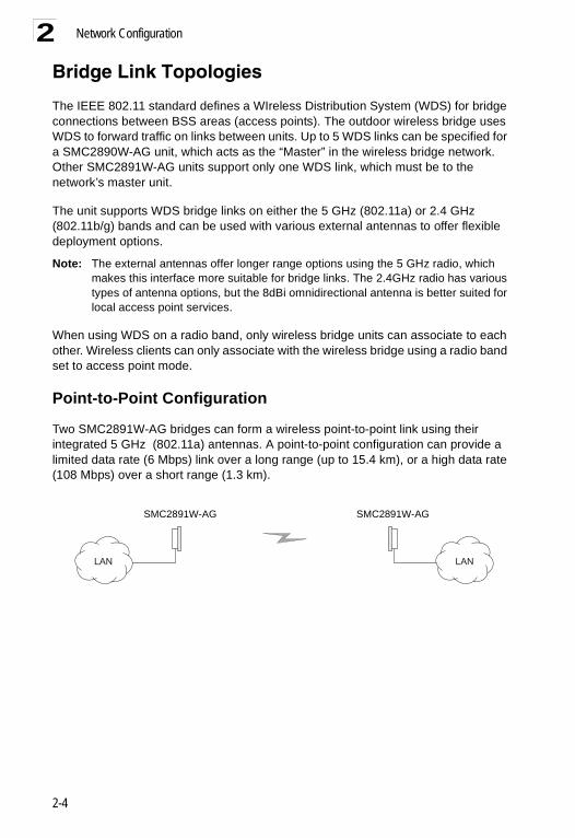
Point-to-Point Configuration
Two SMC2891W-AG bridges can form a wireless point-to-point link using their integrated 5 GHz (802.11a) antennas. A point-to-point configuration can provide a limited data rate (6 Mbps) link over a long range (up to 15.4 km), or a high data rate (108 Mbps) over a short range (1.3 km).
LANLAN
SMC2891W-AG SMC2891W-AG
2-4

Bridge Link Topologies 2
Point-to-Multipoint ConfigurationA SMC2890W-AG wireless bridge can use an omnidirectional or sector antenna to connect to as many as 6 bridges in a point-to-multipoint configuration. There can only be one “Master” unit in the wireless bridge network, all other bridges must be “Slave” units.
Using the 5 GHz 8 dBi omnidirectional external antenna, the SMC2890W-AG can connect to SMC2891W-AG units up to 3.3 km (2 miles) away. Using the 13.5 dBi 120-degree sector antenna, the SMC2890W-AG can connect to SMC2891W-AG units up to 10.3 km (6.4 miles) away.
SMC2890W-AG withOmnidirectional
Antenna
SMC2891W-AG
SMC2891W-AGSMC2891W-AG
SMC2891W-AG
SMC2891W-AGSMC2891W-AG
SMC2890W-AG withSector Antenna
SMC2891W-AG
SMC2891W-AG
SMC2891W-AG
2-5

Network Configuration2
2-6

Chapter 3: Bridge Link Planning
The Dual-band Outdoor Access Point / Bridge supports fixed point-to-point or point-to-multipoint wireless links. A single link between two points can be used to connect a remote site to larger core network. Multiple bridge links can provide a way to connect widespread Ethernet LANs.
For each link in a wireless bridge network to be reliable and provide optimum performance, some careful site planning is required. This chapter provides guidance and information for planning your wireless bridge links.
Note: The planning and installation of the wireless bridge requires professional personnel that are trained in the installation of radio transmitting equipment. The user is responsible for compliance with local regulations concerning items such as antenna power, use of lightning arrestors, grounding, and radio mast or tower construction. Therefore, it is recommended to consult a professional contractor knowledgeable in local radio regulations prior to equipment installation.
Data RatesUsing its 5 GHz integrated antenna, the SMC2891W-AG bridge can operate over a range of up to 15.4 km (9.6 miles) or provide a high-speed connection of 54 Mbps (108 Mbps in turbo mode). However, the maximum data rate for a link decreases as the operating range increases.
When you are planning each wireless bridge link, take into account the maximum distance and data rates for the various antenna options. See “Transmit Power” on page C-5.
Radio Path PlanningAlthough the wireless bridge uses IEEE 802.11a radio technology, which is capable of reducing the effect of multipath signals due to obstructions, the wireless bridge link requires a “radio line-of-sight” between the two antennas for optimum performance.
The concept of radio line-of-sight involves the area along a radio link path through which the bulk of the radio signal power travels. This area is known as the first Fresnel Zone of the radio link. For a radio link not to be affected by obstacles along its path, no object, including the ground, must intrude within 60% of the first Fresnel Zone.
The following figure illustrates the concept of a good radio line-of-sight.
3-1

Bridge Link Planning3
If there are obstacles in the radio path, there may still be a radio link but the quality and strength of the signal will be affected. Calculating the maximum clearance from objects on a path is important as it directly affects the decision on antenna placement and height. It is especially critical for long-distance links, where the radio signal could easily be lost.
When planning the radio path for a wireless bridge link, consider these factors:
• Avoid any partial line-of-sight between the antennas.• Be cautious of trees or other foliage that may be near the path, or may grow and
obstruct the path.• Be sure there is enough clearance from buildings and that no building construction
may eventually block the path.• Check the topology of the land between the antennas using topographical maps,
aerial photos, or even satellite image data (software packages are available that may include this information for your area)
• Avoid a path that may incur temporary blockage due to the movement of cars, trains, or aircraft.
Antenna Height
A reliable wireless link is usually best achieved by mounting the antennas at each end high enough for a clear radio line of sight between them. The minimum height required depends on the distance of the link, obstacles that may be in the path, topology of the terrain, and the curvature of the earth (for links over 3 miles).
For long-distance links, a mast or pole may need to be contsructed to attain the minimum required height. Use the following table to estimate the required minimum clearance above the ground or path obstruction.
Visual Line of Sight Radio Line of Sight
3-2

Radio Path Planning 3
.Note that to avoid any obstruction along the path, the height of the object must be added to the minimum clearance required for a clear radio line-of-sight. Consider the following simple example, illustrated in the figure below.
A wireless bridge link is deployed to connect building A to a building B, which is located three miles (4.8 km) away. Mid-way between the two buidings is a small tree-covered hill. From the above table it can be seen that for a three-mile link, the object clearance required at the mid-point is 5.3 m (17.4 ft). The tree-tops on the hill are at an elevation of 17 m (56 ft), so the antennas at each end of the link need to be at least 22.3 m (73 ft) high. Building A is six stories high, or 20 m (66 ft), so a 2.3 m
Total Link Distance Max Clearance for 60% of First Fresnel Zone at 5.8 GHz
Approximate Clearance for Earth Curvature
Total Clearance Required at Mid-point of Link
0.25 mile (402 m) 4.5 ft (1.4 m) 0 4.5 ft (1.4 m)
0.5 mile (805 m) 6.4 ft (1.95 m) 0 6.4 ft (1.95 m)
1 mile (1.6 km) 9 ft (2.7 m) 0 9 ft (2.7 m)
2 miles (3.2 km) 12.7 ft (3.9 m) 0 12.7 ft (3.9 m)
3 miles (4.8 km) 15.6 ft (4.8 m) 1.8 ft (0.5 m) 17.4 ft (5.3 m)
4 miles (6.4 km) 18 ft (5.5 m) 3.2 ft (1.0 m) 21.2 ft (6.5 m)
5 miles (8 km) 20 ft (6.1 m) 5 ft (1.5 m) 25 ft (7.6 m)
7 miles (11.3 km) 24 ft (7.3 m) 9.8 ft (3.0 m) 33.8 ft (10.3 m)
9 miles (14.5 km) 27 ft (8.2 m) 16 ft (4.9 m) 43 ft (13.1 m)
12 miles (19.3 km) 31 ft (9.5 m) 29 ft (8.8 m) 60 ft (18.3 m)
15 miles (24.1 km) 35 ft (10.7 m) 45 ft (13.7 m) 80 ft (24.4 m)
17 miles (27.4 km) 37 ft (11.3 m) 58 ft (17.7 m) 95 ft (29 m)
A B
3 miles (4.8 km)
5.4 m
17 m20 m
2.4 m
12 m
9 m
1.4 m
Visual Line of Sight Radio Line of Sight
3-3

Bridge Link Planning3
(7.5 ft) mast or pole must be contructed on its roof to achieve the required antenna height. Building B is only three stories high, or 9 m (30 ft), but is located at an elevation that is 12 m (39 ft) higher than bulding A. To mount an anntena at the required height on building B, a mast or pole of only 1.3 m (4.3 ft) is needed.Warning: Never construct a radio mast, pole, or tower near overhead power lines.
Note: Local regulations may limit or prevent construction of a high radio mast or tower. If your wireless bridge link requires a high radio mast or tower, consult a professional contractor for advice.
Antenna Position and Orientation
Once the required antenna height has been determined, other factors affecting the precise position of the wireless bridge must be considered:
• Be sure there are no other radio antennas within 2 m (6 ft) of the wireless bridge• Place the wireless bridge away from power and telephone lines• Avoid placing the wireless bridge too close to any metallic, refective surfaces, such
as roof-installed air-conditioning equipment, tinted windows, wire fences, or water pipes
• The wireless bridge antennas at both ends of the link must be positioned with the same polarization direction, either horizontal or vertical
Antenna Polarization — The wireless bridge’s integrated antenna sends a radio signal that is polarized in a particular direction. The antenna’s receive sensitivity is also higher for radio signals that have the same polarization. To maximize the performance of the wireless link, both antennas must be set to the same polarization direction. The unit should be mounted with the antenna sockets facing upwards.
Antenna sockets should point upwards in a vertical manner
3-4

Ethernet Cabling 3
Radio InterferenceThe avoidance of radio interference is an important part of wireless link planning. Interference is caused by other radio transmissions using the same or an adjacent channel frequency. You should first scan your proposed site using a spectrum analyzer to determine if there are any strong radio signals using the 802.11a channel frequencies. Always use a channel frequency that is furthest away from another signal.
If radio interference is still a problem with your wireless bridge link, changing the antenna polarization direction may improve the situation. This is only recommended when the integrated internal antenna is used.
Weather Conditions
When planning wireless bridge links, you must take into account any extreme weather conditions that are known to affect your location. Consider these factors:
• Temperature — The wireless bridge is tested for normal operation in temperatures from -40°C to 60°C. Operating in temperatures outside of this range may cause the unit to fail.
• Wind Velocity — The wireless bridge can operate in winds up to 44 m/s and survive higher wind speeds up to 66 m/s. You must consider the known maximum wind velocity and direction at the site and be sure that any supporting structure, such as a pole, mast, or tower, is built to withstand this force.
• Lightning — The wireless bridge includes its own built-in lightning protection. However, you should make sure that the unit, any supporting structure, and cables are all properly grounded. Additional protection using lightning rods, lightning arrestors, or surge suppressors may also be employed.
• Rain — The wireless bridge is weatherproofed against rain. Also, prolonged heavy rain has no significant effect on the radio signal. However, it is recommended to apply weatherproof sealing tape around the Ethernet port and antenna connectors for extra protection. If moisture enters a connector, it may cause a degradation in performance or even a complete failure of the link.
• Snow and Ice — Falling snow, like rain, has no significant effect on the radio signal. However, a build up of snow or ice on antennas may cause the link to fail. In this case, the snow or ice has to be cleared from the antennas to restore operation of the link.
Ethernet CablingWhen a suitable antenna location has been determined, you must plan a cable route form the wireless bridge outdoors to the power injector module indoors. Consider these points:
• The Ethernet cable length should never be longer than 100 m (328 ft)• Determine a building entry point for the cable
3-5

Bridge Link Planning3
• Determine if conduits, bracing, or other structures are required for safety orprotection of the cable• For lightning protection at the power injector end of the cable, consider using a
lightning arrestor immediately before the cable enters the building
GroundingIt is important that the wireless bridge, cables, and any supporting structures are properly grounded. The wireless bridge unit includes a grounding screw for attaching a ground wire. Be sure that grounding is available and that it meets local and national electrical codes.
3-6

Chapter 4: Hardware Installation
Before mounting antennas to set up your wireless bridge links, be sure you have selected appropriate locations for each antenna. Follow the guidance and information in Chapter 2, “Wireless Link Planning.”
Also, before mounting units in their intended locations, you should first perform initial configuration and test the basic operation of the wireless bridge links in a controlled environment over a very short range. (See the section “Testing Basic Link Operation” in this chapter.)
The wireless bridge includes its own bracket kit for mounting the unit to a 1.5 to 2 inch diameter steel pole or tube, or to a wall. The pole-mounting bracket allows the unit to be mounted to part of a radio mast or tower structure. The wall-mounting option enables it to be fixed to a building wall or roof when using external antennas.
Hardware installation of the wireless bridge involves these steps:1. Mount the unit on a wall, pole, mast, or tower using the mounting bracket.
2. Mount external antennas directly on the bridge or on the same supporting structure as the bridge and connect them to the bridge unit.
3. Connect the Ethernet cable and a grounding wire to the unit.
4. Connect the power injector to the Ethernet cable, a local LAN switch, and an AC power source.
5. Align antennas at both ends of the link.
Testing Basic Link Operation
Set up the units over a very short range (15 to 25 feet), either outdoors or indoors. Connect the units as indicated in this chapter and be sure to perform all the basic configuration tasks outlined in Chapter 5: "Initial Configuration." When you are satisfied that the links are operating correctly, proceed to mount the units in their intended locations.
Mount the Unit
The bridge can be mounted in the following ways using the included mounting bracket:
• To a 1.5 to 2 inch diameter Pole• To a wall
4-1
4-1

Hardware Installation4
The bridge’s mounting bracket has four parts. One rectangular plate that is used for pole and wall mounting, one square plate that attaches directly to the bridge, and two plates that form an adjustable V-shaped clamp for pole mounting.Mounting on a Pole
Perform the following steps to mount the unit to a 1.5 to 2 inch diameter steel pole or tube using the mounting bracket:
1. Fit the edges of the V-shaped clamp parts into the slots on the flat side of the rectangular plate. The inner slots are for a 1.5 inch diameter pole and the outer slots for a 2 inch diameter pole.
2. Place the V-shaped clamp parts of the bracket around the pole and tighten the securing nuts just enough to hold the bracket to the pole. (The bracket may need to be rotated around the pole during the antenna alignment process.)
3. Attach the square mounting plate to the bridge with the supplied screws.
Fit the edges of the V-shaped part into the slots
Tighten the securing bolts
4-2

Mount the Unit 4
4. Attach the bridge with its mounting plate to the bracket already fixed to the pole.
5. Use the included nuts to secure the wireless bridge to the pole bracket. Note that the wireless bridge tilt angle may need to be adjusted during the antenna alignment process.
Attach the adjustable rectangular plate to the bridge with supplied screws
Attach the bridge to the plate on the pole
4-3

Hardware Installation4
Be sure to take account of the antenna polarization direction; all antennas in a link must be mounted with the same polarization.Mounting to a Wall
Perform the following steps to mount the unit to a wall using the wall-mounting bracket:
Note: The wall-mounting bracket does not allow the wireless bridge’s intrgrated antenna to be aligned. It is intended for use with the unit using external antennas.
1. Attach the bracket to a wall with flat side flush against the wall (see following figure). Position the bracket in the intended location and mark the position of the four mounting screw holes.
2. Drill four holes in the wall that match the screws and wall plugs included in the bracket kit, then secure the bracket to the wall.
3. Attach the square mounting plate to the bridge with the supplied screws.
4. Use the included nuts to tightly secure the wireless bridge to the bracket.
4-4

Connect External Antennas 4
Connect External Antennas
When deploying a SMC2891W-AG unit for a bridge link or access point operation, you need to mount external antennas and connect them to the bridge. Typically, a bridge link requires a 5 GHz antenna, and access point operation a 2.4 GHz antenna. SMC2890W-AG units also require an external antenna for 2.4 GHz operation.
Perform these steps:1. Mount the external antenna to the same supporting structure as the bridge,
within 3 m (10 ft) distance, using the bracket supplied in the antenna package.
2. Connect the antenna to the bridge’s N-type connector using the RF coaxial cable provided in the antenna package. Some omnidirectional external antennas attach directly to an N-type connector without using a coaxial cable.
3. Apply weatherproofing tape to the antenna connectors to help prevent water entering the connectors.
4. Set the antenna option for the corresponding antenna through the user interface. See “Antenna ID” on page 6-59 and “Antenna Control Method” on page 6-59.
4-5

Hardware Installation4
Connect Cables to the Unit
Warning: Do not connect or disconnect cables or otherwise work with the bridge during periods of lightning activity.
1. Attach the Ethernet cable to the Ethernet port on the wireless bridge.
2. For extra protection against rain or moisture, apply weatherproofing tape (not included) around the Ethernet connector.
3. Be sure to ground the unit with an appropriate grounding wire (not included) by attaching it to the grounding point on the base of the unit using the screw provided in the package.
Caution: Be sure that grounding is available and that it meets local and national electrical codes. For additional lightning protection, use lightning rods, lightning arrestors, or surge suppressors.
Note: The Ethernet cable included with the package is 30 m (100 ft) long.
RF Coaxial Cable
2.4 GHz ExternalOmnidirectionalAntenna
2.4 GHz N-type Connector
5 GHzN-type Connector
5 GHz ExternalHigh-gain PanelAntenna
4-6

Connect the Power Injector 4
Connect the Power Injector
To connect the wireless bridge to a power source:
Caution: Do not install the power injector outdoors. The unit is for indoor installation only.
Caution: Install lightning protection at the power injector end of the Ethernet cable, use a lightning arrestor immediately before the cable enters the building.
Note: The wireless bridge’s Ethernet port does not support Power over Ethernet (PoE) based on the IEEE 802.3af standard. Do not try to power the unit by connecting it directly to a network switch that provides IEEE 802.3af PoE. Always connect the unit to the included power injector module.
1. Connect the Ethernet cable from the wireless bridge to the RJ-45 port labeled “Output” on the power injector.
2. Connect a straight-through unshielded twisted-pair (UTP) cable from a local LAN switch to the RJ-45 port labeled “Input” on the power injector. Use Category 5e or better UTP cable for 10/100BASE-TX connections.
Note: The RJ-45 port on the power injector is an MDI port. If connecting directly to a computer for testing the link, use a crossover cable.
Ground Wire
Ethernet Cable
PoE (Ethernet) PortConsole Port
Grounding Screw
4-7

Hardware Installation4
1. Insert the power cable plug directly into the standard AC receptacle on the power injector.
2. Plug the other end of the power cable into a grounded, 3-pin socket, AC power source.
Note: For International use, you may need to change the AC line cord. You must use a line cord set that has been approved for the receptacle type in your country.
3. Check the LED on top of the power injector to be sure that power is being supplied to the wireless bridge through the Ethernet connection.
Align Antennas
After wireless bridge units have been mounted, connected, and their radios are operating, the antennas must be accurately aligned to ensure optimum performance on the bridge links. This alignment process is particularly important for long-range point-to-point links. In a point-to-multipoint configuration the root bridge uses an omnidirectional or sector antenna, which does not require alignment, but bridge nodes still need to be correctly aligned with the root bridge antennna.• Point-to-Point Configurations – In a point-to-point configuration, the alignment
process requires two people, one at each end of the link. The use of cell phones or two-way radio communication may help with coordination. To start, you can just point the antennas at each other, using binoculars or a compass to set the general direction. For accurate alignment, you must monitor the signal strength LEDs as the antenna moves horizontally and vertically.
• Point-to-Multipoint Configurations – In a point-to-multipoint configuration all bridge nodes must be aligned with the root bridge antenna. The alignment process is the same as in point-to-point links, but only the bridge node end of the link requires the alignment.
Input
Output
Ethernet cable from LAN switch
Ethernet cable to wireless bridge
AC power
Power LED indicator
4-8

Align Antennas 4
The signal strength LEDs indicate the received radio signal strength for a particular bridge link. The more LEDs that turn on, the stronger the signal. Alternatively, you can monitor the Receive Signal Strength Indicator (RSSI) value directly from the management interface. The higher the RSSI value, the stronger the signal.When you move the antenna during alignment, the radio signal from the remote antenna can be seen to have a strong central main lobe and smaller side lobes. The object of the alignment process is to set the antenna so that it is receiving the strongest signal from the central main lobe.
To align the antennas in the link, monitor the signal strength LEDs or the RSSI value in the management interface. Start with one antenna fixed and then perform the following procedure on the other antenna:
Note: The RSSI value can be configured through management interfaces to display a value for specific WDS bridge links. See page 6-40 for more information.
Main LobeMaximum
Horizontal Scan
Vertical Scan
RSSIValue Side Lobe
Maximum
RSSI Value
RemoteAntenna
Maximum Signal Strength Positionfor Horizontal Alignment
Maximum SignalStrength Position forVertical Alignment
Power
Link11a
11b/g
Power
Link11a
11b/g
Power
Link11a
11b/g
High 11a Signal
Medium 11a Signal
Low 11a Signal
4-9

Hardware Installation4
1. Pan the antenna horizontally back and forth while checking the LEDs. If usingthe pole-mounting bracket with the unit, you must rotate the mounting bracket around the pole. Other external antenna brackets may require a different horizontal adjustment.
2. Find the point where the signal is strongest (all LEDs on) and secure the horizontal adjustment in that position.
Note: Sometimes there may not be a central lobe peak because vertical alignment is too far off; only two similar peaks for the side lobes are detected. In this case, fix the antenna so that it is halfway between the two peaks.
3. Loosen the vertical adjustment on the mounting bracket and tilt the antenna slowly up and down while checking the LEDs.
4. Find the point where the signal is strongest and secure the vertical adjustment in that position.
4-10

Chapter 5: Initial Configuration
The Dual-band Outdoor Access Point / Bridge offers a variety of management options, including a web-based interface, a direct connection to the console port, Telnet, Secure Shell (SSH), or using SNMP software.
The initial configuration steps can be made through the web browser interface or CLI. The access point requests an IP address via DHCP by default. If no response is received from the DHCP server, then the access point uses the default address 192.168.2.2. If this address is not compatible with your network, you can first use the command line interface (CLI) as described below to configure a valid address.
Note: Units sold in countries outside the United States are not configured with a specific country code. You must use the CLI to set the country code and enable wireless operation (page 5-3).
Initial Setup through the CLI
Required Connections
The access point provides an RS-232 serial port that enables a connection to a PC or terminal for monitoring and configuration. Attach a VT100-compatible terminal, or a PC running a terminal emulation program to the access point. You can use the console cable provided with this package, or use a cable that complies with the wiring assignments shown on page B-3.
To connect to the console port, complete the following steps:
1. Connect the console cable to the serial port on a terminal, or a PC running terminal emulation software, and tighten the captive retaining screws on the DB-9 connector.
2. Connect the other end of the cable to the RS-232 serial port on the access point.
3. Make sure the terminal emulation software is set as follows:• Select the appropriate serial port (COM port 1 or 2).• Set the data rate to 9600 baud.• Set the data format to 8 data bits, 1 stop bit, and no parity.• Set flow control to none.• Set the emulation mode to VT100.• When using HyperTerminal, select Terminal keys, not Windows keys.
4. Once you have set up the terminal correctly, press the [Enter] key to initiate the console connection. The console login screen will be displayed.
5-1

Initial Configuration5
For a description of how to use the CLI, see “Using the Command Line Interface” on page 7-1. For a list of all the CLI commands and detailed information on using the CLI, refer to “Command Groups” on page 7-6.Initial Configuration Steps
Logging In – Enter “admin” for the user name. The default password is null, so just press [Enter] at the password prompt. The CLI prompt appears displaying the access point’s name.
Setting the IP Address – By default, the access point is configured to obtain IP address settings from a DHCP server. If a DHCP server is not available, the IP address defaults to 192.168.2.2, which may not be compatible with your network. You will therefore have to use the command line interface (CLI) to assign an IP address that is compatible with your network.
Type “configure” to enter configuration mode, then type “interface ethernet” to access the Ethernet interface-configuration mode.
First type “no ip dhcp” to disable DHCP client mode. Then type “ip address ip-address netmask gateway,” where “ip-address” is the access point’s IP address, “netmask” is the network mask for the network, and “gateway” is the default gateway router. Check with your system administrator to obtain an IP address that is compatible with your network.
After configuring the access point’s IP parameters, you can access the management interface from anywhere within the attached network. The command line interface can also be accessed using Telnet from any computer attached to the network.
Username: adminPassword: SMC Enterprise AP/Bridge#
SMC AP#configureSMC AP(config)#interface ethernetSMC AP(config-if)#
SMC AP(if-ethernet)#no ip dhcpSMC AP(if-ethernet)#ip address 192.168.2.2
255.255.255.0 192.168.2.254SMC AP(if-ethernet)#
5-2

Logging In 5
Setting the Country Code – Units sold in the United States are configured by default to use only radio channels 1-11 in 802.11b or 802.11g mode as defined by FCC regulations. Units sold in other countries are configured by default without a country code (i.e., 99). You must use the CLI to set the country code. Setting the country code restricts operation of the access point to the radio channels and transmit power levels permitted for wireless networks in the specified country.Type “exit” to leave configuration mode. Then type “country ?” to display the list of countries. Select the code for your country, and enter the country command again, following by your country code (e.g., tw for Taiwan).
Note: Command examples shown later in this manual abbreviate the console prompt to “AP” for simplicity.
Logging In
There are only a few basic steps you need to complete to connect the access point to your corporate network, and provide network access to wireless clients.
The access point can be managed by any computer using a web browser (Internet Explorer 5.0 or above, or Netscape 6.2 or above). Enter the default IP address: http://192.168.2.2
Logging In – Enter the username “admin,” the password is null, so just press just leave it blank and click LOGIN. For information on configuring a user name and password, see page 6-28.
SMC AP#country twSMC AP#
5-3

Initial Configuration5
The home page displays the Main Menu.5-4

Chapter 6: System ConfigurationBefore continuing with advanced configuration, first complete the initial configuration steps described in Chapter 4 to set up an IP address for the access point.
The access point can be managed by any computer using a web browser (Internet Explorer 5.0 or above, or Netscape 6.2 or above). Enter the configured IP address of the access point, or use the default address: http://192.168.2.2
To log into the access point, enter the default user name “admin” and then press “LOGIN”. When the home page displays, click on Advanced Setup. The following page will display.
The information in this chapter is organized to reflect the structure of the web screens for easy reference. However, it is recommended that you configure a user name and password as the first step under Administration to control management access to this device (page 6-28).
6-1

System Configuration6
Advanced ConfigurationThe Advanced Configuration pages include the following options.Table 6-1. MenuMenu Description Page
System Configures basic administrative and client access 6-3
Identification Specifies the host name 6-3
TCP / IP Settings Configures the IP address, subnet mask, gateway, and domain name servers
6-4
RADIUS Configures the RADIUS server for wireless client authentication and accounting
6-7
SSH Settings Configures Secure Shell management access 6-11
Authentication Configures 802.1X client authentication, with an option for MAC address authentication
6-12
Filter Control Filters communications between wireless clients, access to the management interface from wireless clients, and traffic matching specific Ethernet protocol types
6-17
VLAN Enables VLAN support and sets the management VLAN ID 6-19
WDS Settings Configures bridge or repeater modes for each radio interface and sets spanning tree parameters
6-21
AP Management Configures access to management interfaces 6-27
Administration Configures user name and password for management access; upgrades software from local file, FTP or TFTP server; resets configuration settings to factory defaults; and resets the access point
6-28
System Log Controls logging of error messages; sets the system clock via SNTP server or manual configuration
6-33
RSSI Configures RSSI value display, bridge link distance, and LED display mode
6-37
SNMP Configures SNMP settings 6-40
SNMP Controls access to this access point from management stations using SNMP, as well as the hosts that will receive trap messages
6-40
SNMP Trap Filters Defines trap filters for SNMPv3 users 6-48
SNMP Targets Specifies SNMPv3 users that will receive trap messages 6-50
Radio Interface A Configures the IEEE 802.11a interface 6-51
Radio Settings Configures common radio signal parameters and other settings for each VAP interface
6-53
Security Enables each virtual access point (VAP) interface, sets the Service Set Identifier (SSID), and configures wireless security
6-70
6-2

Advanced Configuration 6
System IdentificationThe system name for the access point can be left at its default setting. However, modifying this parameter can help you to more easily distinguish different devices in your network.
System Name – An alias for the access point, enabling the device to be uniquely identified on the network. (Default: SMC Enterprise AP/Bridge; Range: 1-32 characters)
Radio Interface G Configures the IEEE 802.11g interface 6-51
Radio Settings Configures common radio signal parameters and other settings for each VAP interface
6-68
Security Enables each VAP interface, sets the SSID, and configures wireless security
6-70
Status Displays information about the access point and wireless clients 6-88
AP Status Displays configuration settings for the basic system and the wireless interface
6-88
Station Station Shows the wireless clients currently associated with the access point
6-91
Event Logs Shows log messages stored in memory 6-93
Table 6-1. MenuMenu Description Page
6-3

System Configuration6
CLI Commands for System Identification – Enter the global configuration mode, and use the system name command to specify a new system name. Then return to the Exec mode, and use the show system command to display the changes to the system identification settings.SMC AP#config 7-8Enter configuration commands, one per line.SMC AP(config)#system name R&D 7-14SMC AP(config)#end 7-90SMC AP#show system 7-24
System Information==============================================================Serial Number :System Up time : 0 days, 0 hours, 32 minutes, 22 secondsSystem Name : Enterprise Wireless APSystem Location :System Contact : ContactSystem Country Code : US - UNITED STATESMAC Address : 00-12-CF-12-34-60Radio A MAC Address : 00-12-CF-12-34-61Radio G MAC Address : 00-12-CF-12-34-65IP Address : 192.168.2.2Subnet Mask : 255.255.255.0Default Gateway : 0.0.0.0VLAN State : DISABLEDManagement VLAN ID(AP): 1IAPP State : ENABLEDDHCP Client : ENABLEDHTTP Server : ENABLEDHTTP Server Port : 80HTTP Session Timeout : 300 sec(s)HTTPS Server : ENABLEDHTTPS Server Port : 443Slot Status : Dual band(a/g)Boot Rom Version : v1.1.6Software Version : v4.3.3.1b05SSH Server : ENABLEDSSH Server Port : 22Telnet Server : ENABLEDDHCP Relay : DISABLED==============================================================
SMC AP#
6-4

Advanced Configuration 6
TCP / IP SettingsConfiguring the access point with an IP address expands your ability to manage the access point. A number of access point features depend on IP addressing to operate.Note: You can use the web browser interface to access IP addressing only if the access point already has an IP address that is reachable through your network.
By default, the access point will be automatically configured with IP settings from a Dynamic Host Configuration Protocol (DHCP) server. However, if you are not using a DHCP server to configure IP addressing, use the CLI to manually configure the initial IP values (see page 5-2). After you have network access to the access point, you can use the web browser interface to modify the initial IP configuration, if needed.
Note: If there is no DHCP server on your network, or DHCP fails, the access point will automatically start up with a default IP address of 192.168.2.2.
DHCP Client (Enable) – Select this option to obtain the IP settings for the access point from a DHCP (Dynamic Host Configuration Protocol) server. The IP address, subnet mask, default gateway, and Domain Name Server (DNS) address are dynamically assigned to the access point by the network DHCP server. (Default: Enabled)
DHCP Client (Disable) – Select this option to manually configure a static address for the access point.
• IP Address: The IP address of the access point. Valid IP addresses consist of four decimal numbers, 0 to 255, separated by periods.
• Subnet Mask: The mask that identifies the host address bits used for routing to specific subnets.
6-5

System Configuration6
• Default Gateway: The default gateway is the IP address of the router for the accesspoint, which is used if the requested destination address is not on the local subnet. If you have management stations, DNS, RADIUS, or other network servers located on another subnet, type the IP address of the default gateway router in the text field provided. Otherwise, leave the address as all zeros (0.0.0.0).
• Primary and Secondary DNS Address: The IP address of Domain Name Servers on the network. A DNS maps numerical IP addresses to domain names and can be used to identify network hosts by familiar names instead of the IP addresses. If you have one or more DNS servers located on the local network, type the IP addresses in the text fields provided. Otherwise, leave the addresses as all zeros (0.0.0.0).
CLI Commands for TCP/IP Settings – From the global configuration mode, enter the interface configuration mode with the interface ethernet command. Use the ip dhcp command to enable the DHCP client, or no ip dhcp to disable it. To manually configure an address, specify the new IP address, subnet mask, and default gateway using the ip address command. To specify DNS server addresses use the dns server command. Then use the show interface ethernet command from the Exec mode to display the current IP settings.
SMC AP(config)#interface ethernet 7-90Enter Ethernet configuration commands, one per line.SMC AP(if-ethernet)#no ip dhcp 7-92SMC AP(if-ethernet)#ip address 192.168.1.2 255.255.255.0 192.168.1.253 7-91SMC AP(if-ethernet)#dns primary-server 192.168.1.55 7-91SMC AP(if-ethernet)#dns secondary-server 10.1.0.55 7-91SMC AP(config)#end 7-8SMC AP#show interface ethernet 7-94Ethernet Interface Information========================================IP Address : 192.168.1.2Subnet Mask : 255.255.255.0Default Gateway : 192.168.1.253Primary DNS : 192.168.1.55Secondary DNS : 10.1.0.55Admin status : UpOperational status : Up========================================SMC AP#
6-6

Advanced Configuration 6
RADIUSRemote Authentication Dial-in User Service (RADIUS) is an authentication protocol that uses software running on a central server to control access to RADIUS-aware devices on the network. An authentication server contains a database of user credentials for each user that requires access to the network.A primary RADIUS server must be specified for the access point to implement IEEE 802.1X network access control and Wi-Fi Protected Access (WPA) wireless security. A secondary RADIUS server may also be specified as a backup should the primary server fail or become inaccessible.
In addition, the configured RADIUS server can also act as a RADIUS Accounting server and receive user-session accounting information from the access point. RADIUS Accounting can be used to provide valuable information on user activity in the network.
Note: This guide assumes that you have already configured RADIUS server(s) to support the access point. Configuration of RADIUS server software is beyond the scope of this guide, refer to the documentation provided with the RADIUS server software.
6-7

System Configuration6
6-8

Advanced Configuration 6
MAC Address Format – MAC addresses can be specified in one of four formats, using no delimeter, with a single dash delimeter, with multiple dash delimeters, and with multiple colon delimeters.VLAN ID Format – A VLAN ID (a number between 1 and 4094) can be assigned to each client after successful authentication using IEEE 802.1X and a central RADIUS server. The user VLAN IDs must be configured on the RADIUS server for each user authorized to access the network. VLAN IDs can be entered as hexadecimal numbers or as ASCII strings.
Primary Radius Server Setup – Configure the following settings to use RADIUS authentication on the access point.
• Radius Status: Enabling Radius Status allows the settings of RADIUS authentication. (Default: Enable)
• IP Address: Specifies the IP address or host name of the RADIUS server.• Port: The UDP port number used by the RADIUS server for authentication
messages. (Range: 1024-65535; Default: 1812)• Key: A shared text string used to encrypt messages between the access point and
the RADIUS server. Be sure that the same text string is specified on the RADIUS server. Do not use blank spaces in the string. (Maximum length: 255 characters)
• Timeout: Number of seconds the access point waits for a reply from the RADIUS server before resending a request. (Range: 1-60 seconds; Default: 5)
• Retransmit attempts: The number of times the access point tries to resend a request to the RADIUS server before authentication fails. (Range: 1-30; Default: 3)
• Accounting Port: The RADIUS Accounting server UDP port used for accounting messages. (Range: 0 or 1024-65535; Default: 0, disabled)
• Interim Update Timeout: The interval between transmitting accounting updates to the RADIUS server. (Range: 60-86400; Default: 3600 seconds)
Note: For the Timeout and Retransmit attempts fields, accept the default values unless you experience problems connecting to the RADIUS server over the network.
Secondary Radius Server Setup – Configure a secondary RADIUS server to provide a backup in case the primary server fails. The access point uses the secondary server if the primary server fails or becomes inaccessible. Once the access point switches over to the secondary server, it periodically attempts to establish communication again with primary server. If communication with the primary server is re-established, the secondary server reverts to a backup role.
6-9

System Configuration6
CLI Commands for RADIUS – From the global configuration mode, use the radius-server address command to specify the address of the primary or secondary RADIUS servers. (The following example configures the settings for the primary RADIUS server.) Configure the other parameters for the RADIUS server. Then use the show show radius command from the Exec mode to display the current settings for the primary and secondary RADIUS servers.SMC AP(config)#radius-server address 192.168.1.25 7-60SMC AP(config)#radius-server port 181 7-61SMC AP(config)#radius-server key green 7-61SMC AP(config)#radius-server timeout 10 7-62SMC AP(config)#radius-server retransmit 5 7-62Enterprise AP(config)#radius-server port-accounting 1813 7-63Enterprise AP(config)#radius-server timeout-interim 500 7-63SMC AP(config)#exitSMC AP#show radius 7-65
Radius Server Information========================================IP : 192.168.1.25Port : 181Key : *****Retransmit : 5Timeout : 10Radius MAC format : no-delimiterRadius VLAN format : HEX========================================
Radius Secondary Server Information========================================IP : 0.0.0.0Port : 1812Key : *****Retransmit : 3Timeout : 5Radius MAC format : no-delimiterRadius VLAN format : HEX========================================SMC AP#
6-10

Advanced Configuration 6
SSH SettingsTelnet is a remote management tool that can be used to configure the access point from anywhere in the network. However, Telnet is not secure from hostile attacks. The Secure Shell (SSH) can act as a secure replacement for Telnet. The SSH protocol uses generated public keys to encrypt all data transfers passing between the access point and SSH-enabled management station clients and ensures that data traveling over the network arrives unaltered. Clients can then securely use the local user name and password for access authentication.Note that SSH client software needs to be installed on the management station to access the access point for management via the SSH protocol.
Notes: 1. The access point supports only SSH version 2.0.
2. After boot up, the SSH server needs about two minutes to generate host encryption keys. The SSH server is disabled while the keys are being generated.
SSH SettingsTelnet Server Status – Enables or disables the Telnet server. (Default: Enabled)
SSH Server Status – Enables or disables the SSH server. (Default: Enabled)
SSH Server Port – Sets the UDP port for the SSH server. (Range: 1-65535; Default: 22)
6-11

System Configuration6
CLI Commands for SSH – To enable the SSH server, use the ip ssh-server enable command from the CLI Ethernet interface configuration mode. To set the SSH server UDP port, use the ip ssh-server port command. To view the current settings, use the show system command from the CLI Exec mode (not shown in the following example).AuthenticationWireless clients can be authenticated for network access by checking their MAC address against the local database configured on the access point, or by using a database configured on a central RADIUS server. Alternatively, authentication can be implemented using the IEEE 802.1X network access control protocol.
A client’s MAC address provides relatively weak user authentication, since MAC addresses can be easily captured and used by another station to break into the network. Using 802.1X provides more robust user authentication using user names and passwords or digital certificates. You can configure the access point to use both MAC address and 802.1X authentication, with client station MAC authentication occurring prior to IEEE 802.1X authentication. However, it is better to choose one or the other, as appropriate.
Take note of the following points before configuring MAC address or 802.1X authentication:
• Use MAC address authentication for a small network with a limited number of users. MAC addresses can be manually configured on the access point itself without the need to set up a RADIUS server, but managing a large number of MAC addresses across many access points is very cumbersome. A RADIUS server can be used to centrally manage a larger database of user MAC addresses.
• Use IEEE 802.1X authentication for networks with a larger number of users and where security is the most important issue. When using 802.1X authentication, a RADIUS server is required in the wired network to centrally manage the credentials of the wireless clients. It also provides a mechanism for enhanced network security using dynamic encryption key rotation or W-Fi Protected Access (WPA).
Note: If you configure RADIUS MAC authentication together with 802.1X, RADIUS MAC address authentication is performed prior to 802.1X authentication. If RADIUS MAC authentication succeeds, then 802.1X authentication is performed. If RADIUS MAC authentication fails, 802.1X authentication is not performed.
• The access point can also operate in a 802.1X supplicant mode. This enables the access point itself to be authenticated with a RADIUS server using a configured MD5 user name and password. This prevents rogue access points from gaining access to the network.
Enterprise AP(if-ethernet)#no ip telnet-server 7-17Enterprise AP(if-ethernet)#ip ssh-server enable 7-16Enterprise AP(if-ethernet)#ip ssh-server port 1124 7-16Enterprise AP(if-ethernet)#exitEnterprise AP(if-ethernet)#configure
6-12

Advanced Configuration 6
MAC Authentication – You can configure a list of the MAC addresses for wireless clients that are authorized to access the network. This provides a basic level of authentication for wireless clients attempting to gain access to the network. A database of authorized MAC addresses can be stored locally on the access point or remotely on a central RADIUS server. (Default: Disabled)
• Disabled: No checks are performed on an associating station’s MAC address.• Local MAC: The MAC address of the associating station is compared against the
local database stored on the access point. Use the Local MAC Authentication section of this web page to set up the local database, and configure all access points in the wireless network service area with the same MAC address database.
• Radius MAC: The MAC address of the associating station is sent to a configured RADIUS server for authentication. When using a RADIUS authentication server for MAC address authentication, the server must first be configured in the Radius window (see “RADIUS” on page 6-7). The database of MAC addresses and filtering policy must be defined in the RADIUS server.
Note: MAC addresses on the RADIUS server can be entered in four different formats (see “RADIUS” on page 6-7).
802.1X Supplicant – The access point can also operate in a 802.1X supplicant mode. This enables the access point itself to be authenticated with a RADIUS server using a configured MD5 user name and password. This prevents rogue access points from gaining access to the network.
6-13

System Configuration6
Local MAC Authentication – Configures the local MAC authentication database. The MAC database provides a mechanism to take certain actions based on a wireless client’s MAC address. The MAC list can be configured to allow or deny network access to specific clients.• System Default: Specifies a default action for all unknown MAC addresses (that is, those not listed in the local MAC database).• Deny: Blocks access for all MAC addresses except those listed in the local
database as “Allow.”
• Allow: Permits access for all MAC addresses except those listed in the local database as “Deny.”
• MAC Authentication Settings: Enters specified MAC addresses and permissions into the local MAC database.• MAC Address: Physical address of a client. Enter six pairs of hexadecimal digits
separated by hyphens; for example, 00-90-D1-12-AB-89.
• Permission: Select Allow to permit access or Deny to block access. If Delete is selected, the specified MAC address entry is removed from the database.
• Update: Enters the specified MAC address and permission setting into the local database.
• MAC Authentication Table: Displays current entries in the local MAC database.
6-14

Advanced Configuration 6
CLI Commands for Local MAC Authentication – Use the mac-authentication server command from the global configuration mode to enable local MAC authentication. Use the mac-authentication session-timeout command to set the authentication interval, and web-redirect command to enable web-based authentication for service billing. Set the default action for MAC addresses not in the local table using the address filter default command, then enter MAC addresses in the local table using the address filter entry command. To remove an entry from the table, use the address filter delete command. To display the current settings, use the show authentication command from the Exec mode.SMC AP(config)#mac-authentication server local 7-73SMC AP(config)#mac-authentication session-timeout 5 7-73SMC AP(config)#web-redirect 7-20SMC AP(config)#address filter default denied 7-71SMC AP(config)#address filter entry 00-70-50-cc-99-1a denied 7-72SMC AP(config)#address filter entry 00-70-50-cc-99-1b allowedSMC AP(config)#address filter entry 00-70-50-cc-99-1c allowedSMC AP(config)#address filter delete 00-70-50-cc-99-1c 7-72SMC AP(config)#exitSMC AP#show authentication 7-69
Authentication Information===========================================================MAC Authentication Server : LOCALMAC Auth Session Timeout Value : 0 min802.1x supplicant : DISABLED802.1x supplicant user : EMPTY802.1x supplicant password : EMPTYAddress Filtering : DENIED
System Default : ALLOW addresses not found in filter table.Filter Table
MAC Address Status----------------- ----------00-70-50-cc-99-1a DENIED00-70-50-cc-99-1b ALLOWED=========================================================SMC AP#
6-15

System Configuration6
CLI Commands for RADIUS MAC Authentication – Use the mac-authentication server command from the global configuration mode to enable remote MAC authentication. Set the timeout value for re-authentication using the mac- authentication session-timeout command. Be sure to also configure connection settings for the RADIUS server (not shown in the following example). To display the current settings, use the show authentication command from the Exec mode.CLI Command for 802.1x Supplicant – To configure the access point to operate as a 802.1X supplicant, first use the 802.1X supplicant user command to set a user name and password for the access point, then use the 802.1X supplicant command to enable the feature. To display the current settings, use the show authentication command from the Exec mode (not shown in the following example)
SMC AP(config)#mac-authentication server remote 7-73SMC AP(config)#mac-authentication session-timeout 300 7-73SMC AP(config)#exitSMC AP#show authentication 7-69
Authentication Information===========================================================MAC Authentication Server : REMOTEMAC Auth Session Timeout Value : 300 min802.1x supplicant : DISABLED802.1x supplicant user : EMPTY802.1x supplicant password : EMPTYAddress Filtering : DENIED
System Default : DENY addresses not found in filter table.Filter Table
MAC Address Status----------------- ----------00-70-50-cc-99-1a DENIED00-70-50-cc-99-1b ALLOWED=========================================================SMC AP#
SMC AP(config)#802.1X supplicant user secureAP dot1xpass 7-69SMC AP(config)#802.1X supplicant 7-69SMC AP(config)#
6-16

Advanced Configuration 6
Filter ControlThe access point can employ network traffic frame filtering to control access to network resources and increase security. You can prevent communications between wireless clients and prevent access point management from wireless clients. Also, you can block specific Ethernet traffic from being forwarded by the access point.Inter Client STAs Communication Filter – Sets the global mode for wireless-to-wireless communications between clients associated to Virtual AP (VAP) interfaces on the access point. (Default: Prevent Inter and Intra VAP client Communication)
• Disabled: All clients can communicate with each other through the access point.• Prevent Intra VAP client communication: When enabled, clients associated with a
specific VAP interface cannot establish wireless communications with each other. Clients can communicate with clients associated to other VAP interfaces.
• Prevent Inter and Intra VAP client communication: When enabled, clients cannot establish wireless communications with any other client, either those associated to the same VAP interface or any other VAP interface.
AP Management Filter – Controls management access to the access point from wireless clients. Management interfaces include the web, Telnet, or SNMP. (Default: Disabled)• Disabled: Allows management access from wireless clients.• Enabled: Blocks management access from wireless clients.
6-17

System Configuration6
Uplink Port MAC Address Filtering Status – Prevents traffic with specified source MAC addresses from being forwarded to wireless clients through the access point. You can add a maximum of four MAC addresses to the filter table. (Default: Disabled)• MAC Address: Specvifies a MAC address to filter, in the form xx-xx-xx-xx-xx-xx.• Permission: Adds or deletes a MAC address from the filtering table.
Ethernet Type Filter – Controls checks on the Ethernet type of all incoming and outgoing Ethernet packets against the protocol filtering table. (Default: Disabled)• Disabled: Access point does not filter Ethernet protocol types.• Enabled: Access point filters Ethernet protocol types based on the configuration of
protocol types in the filter table. If the status of a protocol is set to “ON,” the protocol is filtered from the access point.
Note: Ethernet protocol types not listed in the filtering table are always forwarded by the access point.
Ethernet Type Filter – Enables or disables Ethernet filtering on the port. (Default: Disabled)
CLI Commands for Bridge Filtering – Use the filter local-bridge command from the global configuration mode to prevent wireless-to-wireless communications through the access point. Use the filter ap-manage command to restrict management access from wireless clients. To configure Ethernet protocol filtering, use the filter ethernet-type enable command to enable filtering and the filter ethernet-type protocol command to define the protocols that you want to filter. To remove an entry from the table, use the address filter delete command. To display the current settings, use the show filters command from the Exec mode.
SMC AP(config)#filter local-bridge 7-75SMC AP(config)#filter ap-manage 7-75SMC AP(config)#filter uplink enable 7-76SMC AP(config)#filter uplink add 00-12-34-56-78-9a 7-76SMC AP(config)#filter ethernet-type enable 7-76SMC AP(config)#filter ethernet-type protocol ARP 7-77SMC AP(config)#exitSMC AP#show filters 7-78
Protocol Filter Information=========================================================Local Bridge :ENABLEDAP Management :ENABLEDEthernet Type Filter :ENABLED
Enabled Protocol Filters---------------------------------------------------------Protocol: ARP ISO: 0x0806=========================================================SMC AP#
6-18
Advanced Configuration 6
VLANThe access point can employ VLAN tagging support to control access to network resources and increase security. VLANs separate traffic passing between the access point, associated clients, and the wired network. There can be a VLAN assigned to each associated client, a default VLAN for each VAP (Virtual Access Point) interface, and a management VLAN for the access point.Note the following points about the access point’s VLAN support:
• The management VLAN is for managing the access point through remote management tools, such as the web interface, SSH, SNMP, or Telnet. The access point only accepts management traffic that is tagged with the specified management VLAN ID.
• All wireless clients associated to the access point are assigned to a VLAN. If IEEE 802.1X is being used to authenticate wireless clients, specific VLAN IDs can be configured on the RADIUS server to be assigned to each client. If a client is not assigned to a specific VLAN or if 802.1X is not used, the client is assigned to the default VLAN for the VAP interface with which it is associated. The access point only allows traffic tagged with assigned VLAN IDs or default VLAN IDs to access clients associated on each VAP interface.
• When VLAN support is enabled on the access point, traffic passed to the wired network is tagged with the appropriate VLAN ID, either an assigned client VLAN ID, default VLAN ID, or the management VLAN ID. Traffic received from the wired network must also be tagged with one of these known VLAN IDs. Received traffic that has an unknown VLAN ID or no VLAN tag is dropped.
• When VLAN support is disabled, the access point does not tag traffic passed to the wired network and ignores the VLAN tags on any received frames.
Note: Before enabling VLAN tagging on the access point, be sure to configure the attached network switch port to support tagged VLAN frames from the access point’s management VLAN ID, default VLAN IDs, and other client VLAN IDs. Otherwise, connectivity to the access point will be lost when you enable the VLAN feature.
Using IEEE 802.1X and a central RADIUS server, up to 64 VLAN IDs can be mapped to specific wireless clients, allowing users to remain within the same VLAN as they move around a campus site. This feature can also be used to control access to network resources from clients, thereby improving security.
A VLAN ID (1-4094) can be assigned to a client after successful IEEE 802.1X authentication. The client VLAN IDs must be configured on the RADIUS server for each user authorized to access the network. If a client does not have a configured VLAN ID on the RADIUS server, the access point assigns the client to the configured default VLAN ID for the VAP interface.
Note: When using IEEE 802.1X to dynamically assign VLAN IDs, the access point must have 802.1X authentication enabled and a RADIUS server configured. Wireless clients must also support 802.1X client software.
6-19

System Configuration6
When setting up VLAN IDs for each user on the RADIUS server, be sure to use the RADIUS attributes and values as indicated in the following table.VLAN IDs on the RADIUS server can be entered as hexadecimal digits or a string (see “radius-server vlan-format” on page 7-64).
Note: The specific configuration of RADIUS server software is beyond the scope of this guide. Refer to the documentation provided with the RADIUS server software.
VLAN Classification – Enables or disables VLAN tagging support on the access point.
Native VLAN ID – The VLAN ID that traffic must have to be able to manage the access point. (Range 1-4094; Default: 1)
Number RADIUS Attribute Value
64 Tunnel-Type VLAN (13)
65 Tunnel-Medium-Type 802
81 Tunnel-Private-Group-ID VLANID(1 to 4094 as hexadecimal or string)
6-20

Advanced Configuration 6
WDS SettingsEach access point radio interface can be configured to operate in a bridge or repeater mode, which allows it to forward traffic directly to other access point units. To set up bridge links between access point units, you must configure the wireless Distribution System (WDS) forwarding table by specifying the wireless MAC address of all units to which you want to forward traffic. Up to six WDS bridge or repeater links can be specified for each unit in the wireless bridge network.The Spanning Tree Protocol (STP) can be used to detect and disable network loops, and to provide backup links between bridges. This allows a wireless bridge to interact with other bridging devices (that is, an STP-compliant switch, bridge or router) in your network to ensure that only one route exists between any two stations on the network, and provide backup links which automatically take over when a primary link goes down.
WDS Bridge – Up to six WDS bridge or repeater links (MAC addresses) per radio interface can be specified for each unit in the wireless bridge network. One unit only must be configured as the “root bridge” in the wireless network. The root bridge is the unit connected to the main core of the wired LAN. Other bridges need to specify one “Parent” link to the root bridge or to a bridge connected to the root bridge. The other five WDS links are available as “Child” links to other bridges.
• Bridge Role – Each radio interface can be set to operate in one of the following four modes: (Default: AP)• AP (Access Point): Operates as an access point for wireless clients, providing
connectivity to a wired LAN.
6-21

System Configuration6
• Bridge: Operates as a bridge to other access points. The “Parent” link to the rootbridge must be configured. Up to five other ”Child” links are available to other bridges.
• Repeater: Operates as a wireless repeater, extending the range for remote wireless clients and connecting them to the root bridge. The “Parent” link to the root bridge must be configured. In this mode, traffic is not forwarded to the Ethernet port from the radio interface.
• Root Bridge: Operates as the root bridge in the wireless bridge network. Up to six ”Child” links are available to other bridges in the network.
• Master/Slave Mode – Selects between Master and Slave mode. A single master enables up to five slave links, whereas a slave will have only one link to the master.
• Bridge Parent – The physical layer address of the root bridge unit or the bridge unit connected to the root bridge. (12 hexadecimal digits in the form “xx-xx-xx-xx-xx-xx”)
• Channel Auto Sync – Allows a Bridge Child to automatically find the operating channel used by its Bridge Parent.
Caution:Do not enable Channel Auto Sync on a master bridge if there is no root bridge acting as the master bridge's parent.
• Bridge Child – The physical layer address of other bridge units for which this unit serves as the bridge parent or the root bridge. Note that the first entry under the list of child nodes is reserved for the root bridge, and can only be configured if the role is set to “Root Bridge.” (12 hexadecimal digits in the form “xx-xx-xx-xx-xx-xx”)
6-22

Advanced Configuration 6
Spanning Tree Protocol – STP uses a distributed algorithm to select a bridging device (STP-compliant switch, bridge or router) that serves as the root of the spanning tree network. It selects a root port on each bridging device (except for the root device) which incurs the lowest path cost when forwarding a packet from that device to the root device. Then it selects a designated bridging device from each LAN which incurs the lowest path cost when forwarding a packet from that LAN to the root device. All ports connected to designated bridging devices are assigned as designated ports. After determining the lowest cost spanning tree, it enables all root ports and designated ports, and disables all other ports. Network packets are therefore only forwarded between root ports and designated ports, eliminating any possible network loops.
6-23

System Configuration6
Once a stable network topology has been established, all bridges listen for Hello BPDUs (Bridge Protocol Data Units) transmitted from the root bridge. If a bridge does not get a Hello BPDU after a predefined interval (Maximum Age), the bridge assumes that the link to the root bridge is down. This bridge will then initiate negotiations with other bridges to reconfigure the network to reestablish a valid network topology.• Bridge – Enables/disables STP on the wireless bridge or repeater. (Default: Disabled)
• Bridge Priority – Used in selecting the root device, root port, and designated port. The device with the highest priority becomes the STP root device. However, if all devices have the same priority, the device with the lowest MAC address will then become the root device. (Note that lower numeric values indicate higher priority.)• Range: 0-65535• Default: 32768
• Bridge Max Age – The maximum time (in seconds) a device can wait without receiving a configuration message before attempting to reconfigure. All device ports (except for designated ports) should receive configuration messages at regular intervals. Any port that ages out STP information (provided in the last configuration message) becomes the designated port for the attached LAN. If it is a root port, a new root port is selected from among the device ports attached to the network. (Range: 6-40 seconds)• Default: 20• Minimum: The higher of 6 or [2 x (Hello Time + 1)].• Maximum: The lower of 40 or [2 x (Forward Delay - 1)]
• Bridge Hello Time – Interval (in seconds) at which the root device transmits a configuration message. (Range: 1-10 seconds)• Default: 2• Minimum: 1• Maximum: The lower of 10 or [(Max. Message Age / 2) -1]
• Bridge Forwarding Delay – The maximum time (in seconds) this device waits before changing states (i.e., discarding to learning to forwarding). This delay is required because every device must receive information about topology changes before it starts to forward frames. In addition, each port needs time to listen for conflicting information that would make it return to a discarding state; otherwise, temporary data loops might result. (Range: 4-30 seconds)• Default: 15• Minimum: The higher of 4 or [(Max. Message Age / 2) + 1]• Maximum: 30
• Link Path Cost – This parameter is used by the STP to determine the best path between devices. Therefore, lower values should be assigned to ports attached to faster media, and higher values assigned to ports with slower media. (Path cost takes precedence over port priority.)
6-24

Advanced Configuration 6
• Range: 1-65535• Default: Ethernet interface: 19; Wireless interface: 40• Link Port Priority – Defines the priority used for this port in the Spanning Tree Protocol. If the path cost for all ports on a switch are the same, the port with the highest priority (i.e., lowest value) will be configured as an active link in the spanning tree. This makes a port with higher priority less likely to be blocked if the Spanning Tree Protocol is detecting network loops. Where more than one port is assigned the highest priority, the port with lowest numeric identifier will be enabled.• Default: 128• Range: 0-240, in steps of 16
CLI Commands for WDS Settings – To set the role of the access point radio interface, use the bridge role command from the CLI wireless interface configuration mode. If the role of the radio interface is set to “Bridge” or “Repeater,” the MAC address of the parent node must also be configured using the bridge-link parent command. If the role is set to anything other than “Access Point,” then you should also configure the MAC addresses of the child nodes using the bridge-link child command. To view the current bridge link settings, use the show bridge link command.
Enterprise AP(if-wireless a)#bridge role bridge 7-79Enterprise AP(if-wireless a)#bridge channel-auto-sync enable 7-80Enterprise AP(if-wireless a)#bridge-link child 2 00-08-3e-84-bc-6d 7-81Enterprise AP(if-wireless a)#bridge-link child 3 00-08-3e-85-13-f2Enterprise AP(if-wireless a)#bridge-link child 4 00-08-3e-84-79-31Enterprise AP(if-wireless a)#bridge-link parent 00-08-2d-69-3a-51 7-80Enterprise AP(if-wireless a)#exitEnterprise AP#show bridge link wireless a 7-83
Interface Wireless A WDS Information====================================AP Role: BridgeChannel Auto Sync: EnableParent: 00-08-2d-69-3a-51Child: Child 2: 00-08-3e-84-bc-6d Child 3: 00-08-3e-85-13-f2 Child 4: 00-08-3e-84-79-31 Child 5: 00-00-00-00-00-00 Child 6: 00-00-00-00-00-00STAs: No WDS Stations.Enterprise AP#
6-25

System Configuration6
CLI Commands for STP Settings – If the role of a radio interface is set to Repeater, Bridge or Root Bridge, STP can be enabled on the access point to maintain a valid network topology. To globally enable STP, use the bridge stp enable command from the CLI configuration mode. Then configure the other global STP parameters for the bridge. The path cost and priority for each bridge link can be set using the bridge-link path-cost and bridge-link port-priority command from the Wireless Interface configuration mode. The path cost and priority can also be set for the Ethernet port from the Ethernet Interface configuration mode. To view the current STP settings, use the show bridge stp command.Enterprise AP(config)#bridge stp enable 6-104Enterprise AP(config)#bridge stp forwarding-delay 2500 6-105Enterprise AP(config)#bridge stp hello-time 500 6-106Enterprise AP(config)#bridge stp max-age 4000 6-107Enterprise AP(config)#bridge stp priority 40000 6-108Enterprise AP(config)#interface wireless aEnterprise AP(if-wireless a)#bridge-link path-cost 2 40 6-109Enterprise AP(if-wireless a)#bridge-link port-priority 2 64 6-110Enterprise AP(if-wireless a)#exitEnterprise AP#show bridge stp 6-111
Bridge MAC : 00:30:F1:F0:9A:9CStatus : Disabledpriority : 32768desiginated-root : priority = 0, MAC = 00:00:00:00:00:00root-path-cost : 0root-Port-no : 0Hold Time : 0 SecondsHello Time : 0 SecondsMaximum Age : 0 SecondsForward Delay : 0 Secondsbridge Hello Time : 2 Secondsbridge Maximum Age : 20 Secondsbridge Forward Delay : 5 Secondstime-since-top-change: 3168 Secondstopology-change-count: 0Enterprise AP#
6-26

Advanced Configuration 6
AP ManagementThe Web, Telnet, and SNMP management interfaces are enabled and open to all IP addresses by default. To provide more security for management access to the access point, specific interfaces can be disabled and management restricted to a single IP address or a limited range of IP addresses.Once you specify an IP address or range of addresses, access to management interfaces is restricted to the specified addresses. If anyone tries to access a management interface from an unauthorized address, the access point will reject the connection.
UI Management – Enables or disables management access through Telnet, the Web (HTTP), or SNMP interfaces. (Default: Enabled)
Note: Secure Web (HTTPS) connections are not affected by the UI Management or IP Management settings.
IP Management – Restricts management access to Telnet, Web, and SNMP interfaces to specified IP addresses. (Default: Any IP)
• Any IP: Indicates that any IP address is allowed management access.• Single IP: Specifies a single IP address that is allowed management access.• Multiple IP: Specifies an address range as defined by the entered IP address and
subnet mask. For example, IP address 192.168.1.6 and subnet mask 255.255.255.0, defines all IP addresses from 192.168.2.2 to 192.168.1.254.
6-27

System Configuration6
CLI Commands for AP Management features.Administration
Changing the PasswordManagement access to the web and CLI interface on the access point is controlled through a single user name and password. You can also gain additional access security by using control filters (see “Filter Control” on page 6-17).
To protect access to the management interface, you need to configure an Administrator’s user name and password as soon as possible. If the user name and password are not configured, then anyone having access to the access point may be able to compromise access point and network security. Once a new Administrator has been configured, you can delete the default “admin” user name from the system.
Username – The name of the user. The default name is “admin.” (Length: 3-16 characters, case sensitive)
New Password – The password for management access. (Length: 3-16 characters, case sensitive)
Confirm New Password – Enter the password again for verification.
CLI Commands for the Administrator’s User Name and Password – Use the username and password commands from the CLI configuration mode.
Setting the Timeout IntervalYou can set the timeout interval for web access to the unit, after which the user will have to re-enter the username and password.
SMC AP(config)#apmgmtip multiple 192.168.1.50 255.255.255.0 7-21SMC AP(config)#apmgmtui SNMP enable 7-22
SMC AP(config)#username bob 7-15SMC AP(config)#password admin 7-15SMC AP#
6-28

Advanced Configuration 6
Session Timeout for WEB – Sets the time limit for an idle web interface session. (Range: 0-1800 seconds; Default: 300 seconds; 0 is disabled)
CLI Command for the Web Session Timeout – Use the ip http session-timeout command from the CLI configuration mode.
Upgrading FirmwareYou can upgrade new access point software from a local file on the management workstation, or from an FTP or TFTP server. New software may be provided periodically from your distributor.
After upgrading new software, you must reboot the access point to implement the new code. Until a reboot occurs, the access point will continue to run the software it was using before the upgrade started. Also note that new software that is incompatible with the current configuration automatically restores the access point to the factory default settings when first activated after a reboot.
SMC AP(config)#ip http session-timeout 0 7-18SMC AP(config)#
6-29

System Configuration6
Before upgrading new software, verify that the access point is connected to the network and has been configured with a compatible IP address and subnet mask.
If you need to download from an FTP or TFTP server, take the following additional steps:
• Obtain the IP address of the FTP or TFTP server where the access point software is stored.
• If upgrading from an FTP server, be sure that you have an account configured on the server with a user name and password.
• If VLANs are configured on the access point, determine the VLAN ID with which the FTP or TFTP server is associated, and then configure the management station, or the network port to which it is attached, with the same VLAN ID. If you are managing the access point from a wireless client, the VLAN ID for the wireless client must be configured on a RADIUS server.
Current version – Version number of runtime code.
6-30

Advanced Configuration 6
Firmware Upgrade Local – Downloads an operation code image file from the web management station to the access point using HTTP. Use the Browse button to locate the image file locally on the management station and click Start Upgrade to proceed.• New firmware file: Specifies the name of the code file on the server. The newfirmware file name should not contain slashes (\ or /), the leading letter of the file name should not be a period (.), and the maximum length for file names is 32 characters for files on the access point. (Valid characters: A-Z, a-z, 0-9, “.”, “-”, “_”)
Firmware Upgrade Remote – Downloads an operation code image file from a specified remote FTP or TFTP server. After filling in the following fields, click Start Upgrade to proceed.• New firmware file: Specifies the name of the code file on the server. The new
firmware file name should not contain slashes (\ or /), the leading letter of the file name should not be a period (.), and the maximum length for file names on the FTP/TFTP server is 255 characters or 32 characters for files on the access point. (Valid characters: A-Z, a-z, 0-9, “.”, “-”, “_”)
• IP Address: IP address or host name of FTP or TFTP server.• Username: The user ID used for login on an FTP server.• Password: The password used for login on an FTP server.
Configuration File Backup/Restore – Uploads the current access point configuration file to a specified remote FTP or TFTP server. A configuration file can also be downloaded to the access point to restore a specific configuration.
• Export/Import: Select Export to upload a file to an FTP/TFTP server. Select Import to download a file from an FTP/TFTP server.
• Config file: Specifies the name of the configuration file, which must always be "syscfg." A path on the server can be specified using “/” in the name, providing the path already exists; for example, “myfolder/syscfg.” Other than to indicate a path, the file name must not contain any slashes (\ or /), the leading letter cannot be a period (.), and the maximum length for file names on the FTP/TFTP server is 255 characters. (Valid characters: A-Z, a-z, 0-9, “.”, “-”, “_”)
• IP Address: IP address or host name of FTP or TFTP server.• Username: The user ID used for login on an FTP server.• Password: The password used for login on an FTP server.
Restore Factory Settings – Click the Restore button to reset the configuration settings for the access point to the factory defaults and reboot the system. Note that all user configured information will be lost. You will have to re-enter the default user name (admin) to re-gain management access to this device.
Reboot Access Point – Click the Reset button to reboot the system.
Note: If you have upgraded system software, then you must reboot the access point to implement the new operation code. New software that is incompatible with the current configuration automatically restores the access point to default values when first activated after a reboot.
6-31

System Configuration6
Upon uploading a new configuration file you will be prompted to either restore factory settings, or reboot the unit.CLI Commands for Downloading Software from a TFTP Server – Use the copy tftp file command from the Exec mode and then specify the file type, name, and IP address of the TFTP server. When the download is complete, the dir command can be used to check that the new file is present in the access point file system. To run the new software, use the reset board command to reboot the access point.
SMC AP#copy tftp file 7-571. Application image2. Config file3. Boot block imageSelect the type of download<1,2,3>: [1]:1TFTP Source file name:img.binTFTP Server IP:192.168.2.29
SMC AP#dir 7-59File Name Type File Size-------------------------- ---- -----------dflt-img.bin 2 1319939img.bin 2 1629577syscfg 5 17776syscfg_bak 5 17776
262144 byte(s) available
SMC AP#reset board 7-10Reboot system now? <y/n>: y
6-32

Advanced Configuration 6
System Log The access point can be configured to send event and error messages to a System Log Server. The system clock can also be synchronized with a time server, so that all the messages sent to the Syslog server are stamped with the correct time and date.Enabling System LoggingThe access point supports a logging process that can control error messages saved to memory or sent to a Syslog server. The logged messages serve as a valuable tool for isolating access point and network problems.
System Log Setup – Enables the logging of error messages. (Default: Disable)
Server (1-4) – Enables the sending of log messages to a Syslog server host. Up to four Syslog servers are supported on the access point. (Default: Disable)
Server Name/IP – The IP address or name of a Syslog server. (Default: 0.0.0.0)
UDP Port – The UDP port used by a Syslog server. (Range: 514 or 11024-65535; Default: 514)
Logging Console – Enables the logging of error messages to the console. (Default: Disable)
6-33

System Configuration6
Logging Level – Sets the minimum severity level for event logging. (Default: Informational)The system allows you to limit the messages that are logged by specifying a minimum severity level. The following table lists the error message levels from the most severe (Emergency) to least severe (Debug). The message levels that are logged include the specified minimum level up to the Emergency level.
Note: The access point error log can be viewed using the Event Logs window in the Status section (page 6-93). The Event Logs window displays the last 128 messages logged in chronological order, from the newest to the oldest. Log messages saved in the access point’s memory are erased when the device is rebooted.
Logging Facility Type – Sets the facility type for remote logging of syslog messages. The command specifies the facility type tag sent in syslog messages. (See RFC 3164.) This type has no effect on the kind of messages reported by the switch. However, it may be used by the syslog server to sort messages or to store messages in the corresponding database. (Range: 16-23; Default: 16)
Error Level Description
Emergency System unusable
Alerts Immediate action needed
Critical Critical conditions (e.g., memory allocation, or free memory error - resource exhausted)
Error Error conditions (e.g., invalid input, default used)
Warning Warning conditions (e.g., return false, unexpected return)
Notice Normal but significant condition, such as cold start
Informational Informational messages only
Debug Debugging messages
6-34

Advanced Configuration 6
CLI Commands for System Logging – To enable logging on the access point, use the logging on command from the global configuration mode. The logging level command sets the minimum level of message to log. Use the logging console command to enable logging to the console. Use the logging host command to specify up to four Syslog servers. The CLI also allows the logging facility-type command to set the facility-type number to use on the Syslog server. To view the current logging settings, use the show logging command.Configuring SNTPSimple Network Time Protocol (SNTP) allows the access point to set its internal clock based on periodic updates from a time server (SNTP or NTP). Maintaining an accurate time on the access point enables the system log to record meaningful dates and times for event entries. If the clock is not set, the access point will only record the time from the factory default set at the last bootup.
The access point acts as an SNTP client, periodically sending time synchronization requests to specific time servers. You can configure up to two time server IP addresses. The access point will attempt to poll each server in the configured sequence.
SNTP Server – Configures the access point to operate as an SNTP client. When enabled, at least one time server IP address must be specified.
• Primary Server: The IP address of an SNTP or NTP time server that the access point attempts to poll for a time update.
• Secondary Server: The IP address of a secondary SNTP or NTP time server. The access point first attempts to update the time from the primary server; if this fails it attempts an update from the secondary server.
SMC AP(config)#logging on 7-30SMC AP(config)#logging level alert 7-31SMC AP(config)#logging console 7-31SMC AP(config)#logging host 1 IP 10.1.0.3 514 7-30SMC AP(config)#logging host 1 Port 514 7-30SMC AP(config)#logging facility-type 19 7-32SMC AP(config)#exitSMC AP#show logging 7-33
Logging Information============================================Syslog State : EnabledLogging Console State : EnabledLogging Level : AlertLogging Facility Type : 19Servers 1: 10.1.0.3, UDP Port: 514, State: Enabled 2: 0.0.0.0, UDP Port: 514, State: Disabled 3: 0.0.0.0, UDP Port: 514, State: Disabled 4: 0.0.0.0, UDP Port: 514, State: Disabled=============================================
SMC AP#
6-35

System Configuration6
Note: The access point also allows you to disable SNTP and set the system clockmanually.
Set Time Zone – SNTP uses Coordinated Universal Time (or UTC, formerly Greenwich Mean Time, or GMT) based on the time at the Earth’s prime meridian, zero degrees longitude. To display a time corresponding to your local time, you must indicate the number of hours your time zone is located before (east) or after (west) UTC.
Enable Daylight Saving – The access point provides a way to automatically adjust the system clock for Daylight Savings Time changes. To use this feature you must define the month and date to begin and to end the change from standard time. During this period the system clock is set back by one hour.
CLI Commands for SNTP – To enable SNTP support on the access point, from the global configuration mode specify SNTP server IP addresses using the sntp-server ip command, then use the sntp-server enable command to enable the service. Use the sntp-server timezone command to set the time zone for your location, and the sntp-server daylight-saving command to set daylight savings. To view the current SNTP settings, use the show sntp command.
SMC AP(config)#sntp-server ip 1 10.1.0.19 7-35SMC AP(config)#sntp-server enable 7-35SMC AP(config)#sntp-server timezone +8 7-37SMC AP(config)#sntp-server daylight-saving 7-37Enter Daylight saving from which month<1-12>: 3and which day<1-31>: 31Enter Daylight saving end to which month<1-12>: 10and which day<1-31>: 31SMC AP(config)#exitSMC AP#show sntp 7-38
SNTP Information=========================================================Service State : EnabledSNTP (server 1) IP : 10.1.10.19SNTP (server 2) IP : 192.43.244.18Current Time : 19 : 35, Oct 10th, 2003Time Zone : +8 (TAIPEI, BEIJING)Daylight Saving : Enabled, from Mar, 31st to Oct, 31st=========================================================
SMC AP#
6-36

Advanced Configuration 6
CLI Commands for the System Clock – The following example shows how to manually set the system time when SNTP server support is disabled on the access point.RSSI
The RSSI value displayed on the RSSI page represents a signal to noise ratio. A value of 30 would indicate that the power of the received signal is 30 dBm above the ambient noise floor. This value can be used to align antennas (see page 4-6) and monitor the quality of the received signal for bridge links. An RSSI value of about 30 or more indicates a strong enough signal to support the maximum data rate of 54 Mbps. Below a value of 30, the supported data rate would drop to lower rates. A value of 15 or less indicates that the signal is weak and the antennas may require realignment.
SMC AP(config)#no sntp-server enable 7-35SMC AP(config)#sntp-server date-time 7-36Enter Year<1970-2100>: 2003Enter Month<1-12>: 10Enter Day<1-31>: 10Enter Hour<0-23>: 18Enter Min<0-59>: 35SMC AP(config)#
6-37

System Configuration6
The RSSI controls allow the external connector to be disabled and the receive signal for each WDS port displayed.RSSI:
• Auto Refresh – Enables or disables the refreshing of RSSI information.• RSSI Value – The displayed RSSI value for a selected port.
6-38

Advanced Configuration 6
• Port Number: Selects a specific WDS port for which to display the RSSI outputvalue. Ports 1-6 are available for a Master unit, only port 1 for a Slave unit. (Default: 1)
Distance:
• Mode: Indicates if the 802.11a radio is operating in normal or Turbo mode. (See "Radio Settings A" on page 6-53.)
• Distance: The approximate distance between antennas in a bridge link.LED Status
• Mode – Selects AP mode or Bridge mode.• Bridge Port – Allows the user to select the bridge port on which to monitor traffic.
(Default:1; Range: 1~6)
There are currently no equivalent CLI commands for the RSSI controls.
6-39

System Configuration6
SNMPSimple Network Management Protocol (SNMP) is a communication protocol designed specifically for managing devices on a network. Equipment commonly managed with SNMP includes switches, routers and host computers. SNMP is typically used to configure these devices for proper operation in a network environment, as well as to monitor them to evaluate performance or detect potential problems.Managed devices supporting SNMP contain software, which runs locally on the device and is referred to as an agent. A defined set of variables, known as managed objects, is maintained by the SNMP agent and used to manage the device. These objects are defined in a Management Information Base (MIB) that provides a standard presentation of the information controlled by the agent. SNMP defines both the format of the MIB specifications and the protocol used to access this information over the network.
The access point includes an onboard agent that supports SNMP versions 1, 2c, and 3 clients. This agent continuously monitors the status of the access point, as well as the traffic passing to and from wireless clients. A network management station can access this information using SNMP management software that is compliant with MIB II. To implement SNMP management, the access point must first have an IP address and subnet mask, configured either manually or dynamically. Access to the onboard agent using SNMP v1 and v2c is controlled by community strings. To communicate with the access point, the management station must first submit a valid community string for authentication.
Access to the access point using SNMP v3 provides additional security features that cover message integrity, authentication, and encryption; as well as controlling notifications that are sent to specified user targets.
6-40

SNMP 6
Configuring SNMP and Trap Message ParametersThe access point SNMP agent must be enabled to function (for versions 1, 2c, and 3 clients). Management access using SNMP v1 and v2c also requires community strings to be configured for authentication. Trap notifications can be enabled and sent to up to four management stations.SNMP – Enables or disables SNMP management access and also enables the access point to send SNMP traps (notifications). (Default: Disable)
Location – A text string that describes the system location. (Maximum length: 255 characters)
Contact – A text string that describes the system contact. (Maximum length: 255 characters)
Community Name (Read Only) – Defines the SNMP community access string that has read-only access. Authorized management stations are only able to retrieve MIB objects. (Maximum length: 23 characters, case sensitive; Default: public)
6-41

System Configuration6
Community Name (Read/Write) – Defines the SNMP community access string that has read/write access. Authorized management stations are able to both retrieve and modify MIB objects. (Maximum length: 23 characters, case sensitive; Default: private)Trap Destination (1 to 4) – Enables recipients (up to four) of SNMP notifications.
• Trap Destination IP Address – Specifies the recipient of SNMP notifications. Enter the IP address or the host name. (Host Name: 1 to 63 characters, case sensitive)
• Trap Destination Community Name – The community string sent with the notification operation. (Maximum length: 23 characters, case sensitive; Default: public)
Engine ID – Sets the engine identifier for the SNMPv3 agent that resides on the access point. This engine protects against message replay, delay, and redirection. The engine ID is also used in combination with user passwords to generate the security keys for authenticating and encrypting SNMPv3 packets. A default engine ID is automatically generated that is unique to the access point. (Range: 10 to 64 hexadecimal characters)
Note: If the local engine ID is deleted or changed, all SNMP users will be cleared. All existing users will need to be re-configured. If you want to change the default engine ID, change it first before configuring other SNMP v3 parameters.
6-42

SNMP 6
Trap Configuration – Allows selection of specific SNMP notifications to send. The following items are available:• sysSystemUp - The access point is up and running.• sysSystemDown - The access point is about to shutdown and reboot.• sysRadiusServerChanged - The access point has changed from the primary
RADIUS server to the secondary, or from the secondary to the primary.• sysConfigFileVersionChanged - The access point’s configuration file has been
changed.• dot11StationAssociation - A client station has successfully associated with the
access point.• dot11StationReAssociation - A client station has successfully re-associated with
the access point.• dot11StationAuthentication - A client station has been successfully authenticated.• dot11StationRequestFail - A client station has failed association, re-association, or
authentication.• dot11InterfaceBFail - The 802.11b interface has failed.• dot11InterfaceAFail - The 802.11a or 802.11g interface has failed.• dot1xMacAddrAuthSuccess - A client station has successfully authenticated its
MAC address with the RADIUS server.• dot1xMacAddrAuthFail - A client station has failed MAC address authentication
with the RADIUS server.• dot1xAuthNotInitiated - A client station did not initiate 802.1X authentication.• dot1xAuthSuccess - A 802.1X client station has been successfully authenticated
by the RADIUS server.• dot1xAuthFail - A 802.1X client station has failed RADIUS authentication.• dot1xSuppAuthenticated - A supplicant station has been successfully
authenticated by the RADIUS server• localMacAddrAuthSuccess - A client station has successfully authenticated its
MAC address with the local database on the access point.• localMacAddrAuthFail - A client station has failed authentication with the local MAC
address database on the access point.• iappStationRoamedFrom - A client station has roamed from another access point
(identified by its IP address).• iappStationRoamedTo - A client station has roamed to another access point
(identified by its IP address).• iappContextDataSent - A client station’s Context Data has been sent to another
access point with which the station has associated.• sntpServerFail - The access point has failed to set the time from the configured
SNTP server.• wirelessExternalAntenna - An external antenna has been enabled.• dot11WirelessStationDeauthenticate - A client station has de-authenticated from
the network.
6-43

System Configuration6
• dot11StationDisassociate - A client station no longer associates with the network.• dot11StationAuthenticateFail - A client station has tried and failed to authenticateto the network.• Enable All Traps - Click the button to enable all the available traps.• Disable All Traps - Click the button to disable all the available traps.CLI Commands for SNMP and Trap Configuration – Use the snmp-server enable server command from the global configuration mode to enable the SNMP agent. Use the snmp-server location and snmp-server contact commands to indicate the physical location of the access point and define a system contact. To set the read-only and read/write community names, use the snmp-server community command. Use the snmp-server host command to define a trap receiver host and the snmp-server trap command to enable or disable specific traps.
SMC AP(config)#snmp-server enable server 7-43SMC AP(config)#snmp-server community alpha rw 7-42SMC AP(config)#snmp-server community beta roSMC AP(config)#snmp-server location WC-19 7-43SMC AP(config)#snmp-server contact Paul 7-42SMC AP(config)#snmp-server host 192.168.1.9 alpha 7-44Enterprise AP(config)#snmp-server trap dot11StationAssociation 7-45Enterprise AP(config)#
6-44

SNMP 6
To view the current SNMP settings, use the show snmp command.SMC AP#show snmp 7-55
SNMP Information==============================================Service State : EnableCommunity (ro) : *****Community (rw) : *****Location : WC-19Contact : Paul
EngineId :80:00:07:e5:80:00:00:2e:62:00:00:00:18EngineBoots:1
Trap Destinations: 1: 192.168.1.9, Community: *****, State: Enabled 2: 0.0.0.0, Community: *****, State: Disabled 3: 0.0.0.0, Community: *****, State: Disabled 4: 0.0.0.0, Community: *****, State: Disabled
dot11InterfaceAGFail Enabled dot11InterfaceBFail Enabled dot11StationAssociation Enabled dot11StationAuthentication Enableddot11StationReAssociation Enabled dot11StationRequestFail Enabled dot1xAuthFail Enabled dot1xAuthNotInitiated Enabled dot1xAuthSuccess Enabled dot1xMacAddrAuthFail Enabled dot1xMacAddrAuthSuccess Enabled iappContextDataSent Enabled iappStationRoamedFrom Enabled iappStationRoamedTo Enabled localMacAddrAuthFail Enabled localMacAddrAuthSuccess Enabled iappContextDataSent Enabled dot1XSuppAuthenticated Enabled wirelessExternalAntenna Enabled dot11InterfaceAFail Enabled dot11InterfaceGFail Enabled pppLogonFail Enabled sntpServerFail Enabled configFileVersionChanged Enabled radiusServerChanged Enabled systemDown Enabled systemUp Enabled
=============================================Enterprise AP#
6-45

System Configuration6
Configuring SNMPv3 UsersThe access point allows up to 10 SNMP v3 users to be configured. Each user must be defined by a unique name, assigned to one of three pre-defined security groups, and configured with specific authentication and encryption settings.User – The SNMPv3 user name. (32 characters maximum)
Group – The SNMPv3 group name. (Options: RO, RWAuth, or RWPriv; Default: RO)• RO – Read-only access.• RWAuth – Read/write access with user authentication.• RWPriv – Read/write access with both user authentication and data encryption.
Auth Type – The authentication type used for the SNMP user; either MD5 or none. When MD5 is selected, enter a password in the corresponding Passphrase field.
Priv Type – The data encryption type used for the SNMP user; either DES or none. When DES is selected, enter a key in the corresponding Passphrase field.
Passphrase – The password or key associated with the authentication and privacy settings. A minimum of eight plain text characters is required.
Action – Click the Add button to add a new user to the list. Click the edit button to change details of an existing user. Click the Del button to remove a user from the list.
Note: Users must be assigned to groups that have the same security levels. For example, a user who has “Auth Type” and “Priv Type” configured to MD5 and DES respectively (that it, uses both authentication and data encryption) must be assigned to the RWPriv group. If this same user were instead assigned to the read-only (RO) group, the user would not be able to access the database.
6-46

SNMP 6
CLI Commands for Configuring SNMPv3 Users – Use the snmp-server engine-id command to define the SNMP v3 engine before assigning users to groups. Use the snmp-server user command to assign users to one of the three groups and set the appropriate authentication and encryption types to be used. To view the current SNMP v3 engine ID, use the show snmp command. To view SNMP users and group settings, use the show snmp users or show snmp group-assignments commands.Enterprise AP(config)#snmp-server engine-id 1a:2b:3c:4d:00:ff 7-46Enterprise AP(config)#snmp-server user 7-47User Name<1-32> :chrisGroup Name<1-32> :RWPrivAuthtype(md5,<cr>none):md5Passphrase<8-32>:a good secretPrivacy(des,<cr>none) :desPassphrase<8-32>:a very good secretEnterprise AP(config)#exitEnterprise AP#show snmp users 7-52
=============================================UserName :chrisGroupName :RWPrivAuthType :MD5 Passphrase:****************PrivType :DES Passphrase:****************=============================================Enterprise AP#show snmp group-assignments 7-52
GroupName :RWPrivUserName :chrisEnterprise AP#
6-47

System Configuration6
Configuring SNMPv3 Trap FiltersSNMP v3 users can be configured to receive notification messages from the access point. An SNMP Target ID is created that specifies the SNMP v3 user, IP address, and UDP port. A user-defined notification filter can be created so that specific notifications can be prevented from being sent to particular targets.The access point allows up to 10 notification filters to be created. Each filter can be defined by up to 20 MIB subtree ID entries.
To configure a new notification filter, click the New button. A new page opens to configure the filter (see below). To edit an existing filter, select the radio button next to the entry in the table and then click the Edit button. To delete a filter, select the radio button next to the entry in the table and then click the Delete button.
When you click on the New button in the SNMP Trap Filters page, a new page opens where the filter parameters are configured. Define a filter name and subtree ID to be filtered. Select the filter type, include or exclude, from the drop-down list. Click Apply to create the filter.
To add more subtree IDs to the filter, return to the SNMP Trap Filters page and click the Edit button. In the Edit page, click the New button to access the Add SNMP Notification Subtree page and configure a new subtree ID to be filtered.
Note: Only the New Filter page allows the Filter ID to be configured.
6-48

SNMP 6
Filter ID – A user-defined name that identifies the filter. (Maximum length: 32 characters)
Subtree OID – Specifies MIB subtree to be filtered. The MIB subtree must be defined in the form “.1.3.6.1” and always start with a “.”.
Filter Type – Indicates if the filter is to “include” or “exclude” the MIB subtree objects from the filter. Note that MIB objects included in the filter are not sent to the receiving target and objects excluded are sent. By default all traps are sent, so you can first use an “include” filter entry for all trap objects. Then use “exclude” entries for the required trap objects to send to the target. Note that the filter entries are applied in the sequence that they are defined.
CLI Commands for Configuring SNMPv3 Trap Filters – To create a notification filter, use the snmp-server filter command from the CLI configuration mode. Use the command more than once with the same filter ID to build a filter that includes or excludes multiple MIB objects. To view the current SNMP filters, use the show snmp filter command from the CLI Exec mode.
Enterprise AP(config)#snmp-server filter trapfilter include .1 7-50Enterprise AP(config)#snmp-server filter trapfilter exclude .1.3.6.1.2.1.2.2.1.1.23Enterprise AP(config)#exitEnterprise AP#show snmp filter 7-53
Filter: trapfilter Type: include Subtree: iso
Type: exclude Subtree: iso.3.6.1.2.1.2.2.1.1.23=============================Enterprise AP#
6-49

System Configuration6
Configuring SNMPv3 TargetsAn SNMP v3 notification Target ID is specified by the SNMP v3 user, IP address, and UDP port. A user-defined filter can also be assigned to specific targets to limit the notifications received to specific MIB objects. (Note that the filter must first be configured. See “Configuring SNMPv3 Trap Filters” on page 6-48)To configure a new notification receiver target, click the New button. A new page opens to configure the settings (see below). To edit an existing target, select the radio button next to the entry in the table and then click the Edit button. To delete targets, select the radio button next to the entry in the table and then click the Delete button.
When you click on the New or Edit button in the SNMP Targets page, a new page opens where the target parameters are configured. Define the parameters and select a filter, if required. Note that the SNMP v3 user name must first be defined (See “Configuring SNMPv3 Users” on page 6-46). Click Apply.
Note: The Target ID cannot be changed in the Edit Target page. Only the New Target page allows the Target ID to be configured.
Target ID – A user-defined name that identifies a receiver of notifications. The access point supports up to 10 target IDs. (Maximum length: 32 characters)
IP Address – Specifies the IP address of the receiving management station.
6-50

Radio Interface 6
UDP Port – The UDP port that is used on the receiving management station for notification messages.SNMP User – The defined SNMP v3 user that is to receive notification messages.
Assigned Filter – The name of a user-defined notification filter that is applied to the target.
CLI Commands for Configuring SNMPv3 Targets – To create a notification target, use the snmp-server targets command from the CLI configuration mode. To assign a filter to a target, use the snmp-server filter-assignment command. To view the current SNMP targets, use the show snmp target command from the CLI Exec mode. To view filter assignment to targets, use the show snmp filter-assignments command.
Radio InterfaceThe IEEE 802.11a and 802.11g interfaces include configuration options for radio signal characteristics and wireless security features. The configuration options are nearly identical, and are therefore both covered in this section of the manual.
The access point can operate in three modes, IEEE 802.11a only, 802.11b/g only, or a mixed 802.11a/b/g mode. Also note that 802.11g is backward compatible with 802.11b. These interfaces are configured independently under the following web pages:
• Radio Interface A: 802.11a • Radio Interface G: 802.11b/g
Enterprise AP(config)#snmp-server targets mytraps 192.168.1.33 chris 7-49Enterprise AP(config)#snmp-server filter-assignment mytraps trapfilter 7-51Enterprise AP(config)#exitEnterprise AP#show snmp target 7-53
Host ID : mytrapsUser : chrisIP Address : 192.168.1.33UDP Port : 162=============================Enterprise AP#show snmp filter-assignments 7-54
HostID FilterID
mytraps trapfilterEnterprise AP#
6-51

System Configuration6
Each radio supports up to four virtual access point (VAP) interfaces numbered 0 to 3. Each VAP functions as a separate access point, and can be configured with its own Service Set Identification (SSID) and security settings. However, most radio signal parameters apply to all four VAP interfaces.The VAPs function similar to a VLAN, with each VAP mapped to its own VLAN ID. Traffic to specific VAPs can be segregated based on user groups or application traffic. Each VAP can have up to 64 wireless clients, whereby the clients associate with these VAPs the same as they would with a physical access point.
Note: The radio channel settings for the access point are limited by local regulations, which determine the number of channels that are available. Refer to “General Specifications” on page C-1 for additional information on the maximum number channels available.
6-52

Radio Interface 6
Radio Settings A (802.11a)The IEEE 802.11a interface operates within the 5 GHz band, at up to 54 Mbps in normal mode or up to 108 Mbps in Turbo mode.First configure the radio settings that apply to the individual VAPs (Virtual Access Point) and the common radio settings that apply to the overall system. After you have configured the radio settings, go to the Security page under the 802.a Interface (See “Security” on page 6-70), enable the radio service for any of the VAP interfaces, and then set an SSID to identify the wireless network service provided by each VAP. Remember that only clients with the same SSID can associate with a VAP.
Note: You must first enable VAP interface 0 before the other interfaces can be enabled.
Configuring VAP Radio SettingsTo configure VAP radio settings, select the Radio Settings page.
6-53

System Configuration6
Default VLAN ID – The VLAN ID assigned to wireless clients associated to the VAP interface that are not assigned to a specific VLAN by RADIUS server configuration. (Default: 1)
Closed System – When enabled, the VAP interface does not include its SSID in beacon messages. Nor does it respond to probe requests from clients that do not include a fixed SSID. (Default: Disable)
Authentication Timeout Interval – The time within which the client should finish authentication before authentication times out. (Range: 5-60 minutes; Default: 60 minutes)
Association Timeout Interval – The idle time interval (when no frames are sent) after which a client is disassociated from the VAP interface. (Range: 5-60 minutes; Default: 30 minutes)
WPA2 PMKSA Life Time – WPA2 provides fast roaming for authenticated clients by retaining keys and other security settings in a cache for each VAP. In this way, when clients roam back into a VAP they had previously been using, re-authentication is not required. When a WPA2 client is first authenticated, it receives a Pairwise Master Key (PMK) that is used to generate the other keys used for unicast data encryption. This key and other client information form a client Security Association (SA) that the VAP holds in a cache. When the lifetime expires, the security association and keys are deleted from the cache. If the client returns to an access point after the association has been deleted, it will require full re-authentication. (Range: 1-1440 minutes; Default: 720 minutes)
6-54

Radio Interface 6
CLI Commands for the Configuring the VAPs – From the global configuration mode, enter the interface wireless a command to access the 802.11a radio interface. From the 802.11a interface mode, you can access radio settings that apply to all VAP interfaces. To access a specific VAP interface (numbered 0 to 3), use the vap command. You can configure a name for each interface using the description command. You can also use the closed-system command to stop sending the SSID in beacon messages. Set any other VAP parameters and radio setting as required before enabling the VAP interface (with the no shutdown command). To view the current 802.11a radio settings for the VAP interface, use the show interface wireless a [0-3] command as shown on 7-97.Configuring Rogue AP DetectionTo configure Rouge AP detection, select the Radio Settings page, and scroll down to the “Rouge AP” section.
Rogue AP – A “rogue AP” is either an access point that is not authorized to participate in the wireless network, or an access point that does not have the correct security configuration. Rogue APs can allow unauthorized access to the network, or fool client stations into mistakenly associating with them and thereby blocking access to network resources. The access point can be configured to periodically scan all radio channels and find other access points within range. A database of nearby access points is maintained where any rogue APs can be identified. During a scan, Syslog messages (see “Enabling System Logging” on page 6-33) are sent for each access point detected. Rogue access points can be identified by unknown BSSID (MAC address) or SSID configuration.
SMC AP(if-wireless a)#vap 0 7-97SMC AP(if-wireless a: VAP[0])#description RD-AP#3 7-109SMC AP(if-wireless a: VAP[0])#vlan-id 1 7-136SMC AP(if-wireless a: VAP[0])#closed-system 7-110Enterprise AP(if-wireless a: VAP[0])#authentication-timeout- interval 30 7-111Enterprise AP(if-wireless a: VAP[0])#association-timeout- interval 20 7-111SMC AP(if-wireless a: VAP[0])#max-association 32 7-110SMC AP(if-wireless a: VAP[0])#pmksa-lifetime 900 7-128Enterprise AP(if-wireless a: VAP[0])#
6-55

System Configuration6
• AP Detection – Enables the periodic scanning for other access points.(Default: Disable)• AP Scan Interval – Sets the time between each rogue AP scan. (Range: 30 -10080
minutes; Default: 720 minutes)• AP Scan Duration – Sets the length of time for each rogue AP scan. A long scan
duration time will detect more access points in the area, but causes more disruption to client access. (Range: 100 -1000 milliseconds; Default: 350 milliseconds)
• Rogue AP Authenticate – Enables or disables RADIUS authentication. Enabling RADIUS Authentication allows the access point to discover rogue access points. With RADIUS authentication enabled, the access point checks the MAC address/ Basic Service Set Identifier (BSSID) of each access point that it finds against a RADIUS server to determine whether the access point is allowed. With RADIUS authentication disabled, the access point can detect its neighboring access points only; it cannot identify whether the access points are allowed or are rogues. If you enable RADIUS authentication, you must configure a RADIUS server for this access point (See “RADIUS” on page 6-7).
• Scan AP Now – Starts an immediate rogue AP scan on the radio interface. (Default: Disable)
Note: While the access point scans a channel for rogue APs, wireless clients will not be able to connect to the access point. Therefore, avoid frequent scanning or scans of a long duration unless there is a reason to believe that more intensive scanning is required to find a rogue AP.
CLI Commands for Rogue AP Detection – From the global configuration mode, enter the interface wireless command to access the 802.11a or 802.11g radio interface. From the wireless interface mode, use the rogue-ap enable command to enable rogue AP detection. Set the duration and interval times with the rogue-ap duration and rogue-ap interval commands. If required, start an immediate scan
6-56

Radio Interface 6
using the rogue-ap scan command. To view the database of detected access points, use the show rogue-ap command from the Exec level.SMC AP(config)#interface wireless g 7-90Enter Wireless configuration commands, one per line.SMC AP(if-wireless g)#rogue-ap enable 7-116configure either syslog or trap or both to receive the rogue APs detected.SMC AP(if-wireless g)#rogue-ap duration 200 7-118SMC AP(if-wireless g)#rogue-ap interval 120 7-118SMC AP(if-wireless g)#rogue-ap scan 7-119SMC AP(if-wireless g)#rogueApDetect Completed (Radio G) : 5 APs detectedrogueAPDetect (Radio G): refreshing ap database now
SMC AP(if-wireless g)#exitSMC AP#show rogue-ap 7-120
802.11a Channel : Rogue AP StatusAP Address(BSSID) SSID Channel(MHz) RSSI=======================================================
802.11g Channel : Rogue AP StatusAP Address(BSSID) SSID Channel(MHz) RSSI=======================================================00-04-e2-2a-37-23 WLAN1AP 11(2462 MHz) 1700-04-e2-2a-37-3d ANY 7(2442 MHz) 4200-04-e2-2a-37-49 WLAN1AP 9(2452 MHz) 4200-90-d1-08-9d-a7 WLAN1AP 1(2412 MHz) 1200-30-f1-fb-31-f4 WLAN 6(2437 MHz) 16SMC AP#
6-57

System Configuration6
Configuring Common Radio SettingsTo configure common radio settings, select the Radio Settings page, and scroll down to below the VAP radio settings.Turbo Mode – The normal 802.11a wireless operation mode provides connections up to 54 Mbps. Turbo Mode is an enhanced mode (not regulated in IEEE 802.11a) that provides a higher data rate of up to 108 Mbps. Enabling Turbo Mode allows the access point to provide connections up to 108 Mbps. (Default: Disabled)Note: In normal mode, the access point provides a channel bandwidth of 20 MHz, and
supports the maximum number of channels permitted by local regulations (e.g., 13 channels for the United States). In Turbo Mode, the channel bandwidth is increased to 40 MHz to support the increased data rate. However, this reduces the number of channels supported (e.g., 5 channels for the United States).
Note: Check your country’s regulations to see if Turbo Mode is allowed.
6-58

Radio Interface 6
Radio Channel – The radio channel that the access point uses to communicate with wireless clients. When multiple access points are deployed in the same area, set the channel on neighboring access points at least four channels apart to avoid interference with each other. For example, in the United States you can deploy up to four access points in the same area (e.g., channels 36, 56, 149, 165). Also note that the channel for wireless clients is automatically set to the same as that used by the access point to which it is linked. (Default: Channel 60 for normal mode, and channel 42 for Turbo mode)Auto Channel Select – Enables the access point to automatically select an unoccupied radio channel. (Default: Enabled)
Note: Check your country’s regulations to see if Auto Channel can be disabled.
Transmit Power – Adjusts the power of the radio signals transmitted from the access point. The higher the transmission power, the farther the transmission range. Power selection is not just a trade off between coverage area and maximum supported clients. You also have to ensure that high-power signals do not interfere with the operation of other radio devices in the service area. (Options: 100%, 50%, 25%, 12%, minimum; Default: 100%)
Note: When operating the access point using 5 GHz channels in a European Community country, the end user and installer are obligated to operate the device in accordance with European regulatory requirements for Transmit Power Control (TPC).
Maximum Supported Rate – The maximum data rate at which the access point transmits unicast packets on the wireless interface. The maximum transmission distance is affected by the data rate. The lower the data rate, the longer the transmission distance. (Options: 54, 48, 36, 24 Mbps; Default: 54 Mbps)
Maximum Associated Clients – Sets the maximum number of clients that can be associated with a VAP interface at the same time. (Range: 1-64 per VAP interface: Default: 64)
Antenna ID – Selects the antenna to be used by the access point. (Default: Integrated antenna; ID: 0000. If there is no integrated antenna, "id=0x0000, module=NA" is displayed in the list.)
Note: The Antenna ID must be selected in conjunction with the Antenna Control Method to configure proper use of any of the antenna options.
Antenna Control Method - Selects the use of two antennas operating in diversity mode or a single antenna. (Default: Diversity)
• Diversity: The radio uses two identical antennas in a diversity system.
Normal Mode
Turbo Mode
6-59
System Configuration6
• Right: The radio uses a single antenna on the right side. Select this method whenusing an optional external antenna that is connected to the right antenna connector.
• Left: The radio uses a single antenna on the left side. Select this method when using an optional external antenna that is connected to the left antenna connector. Also select this method when using the integrated 5 GHz antenna.
Antenna Location – Selects the mounting location of the antenna in use; either “Indoor” or “Outdoor.” Selecting the correct location ensures that the access point only uses radio channels that are permitted in the country of operation. (Default: Indoor)
MIC Mode – The Michael Integrity Check (MIC) is part of the Temporal Key Integrity Protocol (TKIP) encryption used in Wi-Fi Protected Access (WPA) security. The MIC calculation is performed in the access point for each transmitted packet and this can impact throughput and performance. The access point supports a choice of software or hardware MIC calculation. The performance of the access point can be improved by selecting the best method for the specific deployment. (Default: Software)
• Hardware: Provides best performance when the number of supported clients is less than 27.
• Software: Provides the best performance for a large number of clients on one radio interface. Throughput may be reduced when both 802.11a and 802.11g interfaces are supporting a high number of clients simultaneously.
Super A – The Atheros proprietary Super A performance enhancements are supported by the access point. These enhancements include bursting, compression, and fast frames. Maximum throughput ranges between 40 to 60 Mbps for connections to Atheros-compatible clients. (Default: Disabled)
Beacon Interval – The rate at which beacon signals are transmitted from the access point. The beacon signals allow wireless clients to maintain contact with the access point. They may also carry power-management information. (Range: 20-1000 TUs; Default: 100 TUs)
Data Beacon Rate – The rate at which stations in sleep mode must wake up to receive broadcast/multicast transmissions.
Known also as the Delivery Traffic Indication Map (DTIM) interval, it indicates how often the MAC layer forwards broadcast/multicast traffic, which is necessary to wake up stations that are using Power Save mode. The default value of 2 indicates that the access point will save all broadcast/multicast frames for the Basic Service Set (BSS) and forward them after every second beacon. Using smaller DTIM intervals delivers broadcast/multicast frames in a more timely manner, causing stations in Power Save mode to wake up more often and drain power faster. Using higher DTIM values reduces the power used by stations in Power Save mode, but delays the transmission of broadcast/multicast frames.(Range: 1-255 beacons; Default: 1 beacon)
6-60

Radio Interface 6
Multicast Data Rate – The maximum data rate at which the access point transmits multicast and broadcast packets on the wireless interface. (Options: 24, 12, 6 Mbps; Default: 6 Mbps)Fragmentation Length – Configures the minimum packet size that can be fragmented when passing through the access point. Fragmentation of the PDUs (Package Data Unit) can increase the reliability of transmissions because it increases the probability of a successful transmission due to smaller frame size. If there is significant interference present, or collisions due to high network utilization, try setting the fragment size to send smaller fragments. This will speed up the retransmission of smaller frames. However, it is more efficient to set the fragment size larger if very little or no interference is present because it requires overhead to send multiple frames. (Range: 256-2346 bytes; Default: 2346 bytes)
RTS Threshold – Sets the packet size threshold at which a Request to Send (RTS) signal must be sent to a receiving station prior to the sending station starting communications. The access point sends RTS frames to a receiving station to negotiate the sending of a data frame. After receiving an RTS frame, the station sends a CTS (clear to send) frame to notify the sending station that it can start sending data.
If the RTS threshold is set to 0, the access point always sends RTS signals. If set to 2347, the access point never sends RTS signals. If set to any other value, and the packet size equals or exceeds the RTS threshold, the RTS/CTS (Request to Send / Clear to Send) mechanism will be enabled.
The access points contending for the medium may not be aware of each other. The RTS/CTS mechanism can solve this “Hidden Node Problem.” (Range: 0-2347 bytes: Default: 2347 bytes)
6-61

System Configuration6
CLI Commands for the Common Radio Settings – From the global configuration mode, enter the interface wireless a command to access the 802.11a radio interface. From the 802.11a interface mode, you can access radio settings that apply to all VAP interfaces. Use the turbo command to enable this feature before setting the radio channel with the channel command. Set any other radio setting as required before enabling the VAP interface (with the no shutdown command). To view the current 802.11a radio settings for the VAP interface, use the show interface wireless a [0~3] command as shown on 7-97.Configuring Wi-Fi MultimediaWireless networks offer an equal opportunity for all devices to transmit data from any type of application. Although this is acceptable for most applications, multimedia applications (with audio and video) are particularly sensitive to the delay and throughput variations that result from this “equal opportunity” wireless access method. For multimedia applications to run well over a wireless network, a Quality of Service (QoS) mechanism is required to prioritize traffic types and provide an “enhanced opportunity” wireless access method.
The access point implements QoS using the Wi-Fi Multimedia (WMM) standard. Using WMM, the access point is able to prioritize traffic and optimize performance when multiple applications compete for wireless network bandwidth at the same time. WMM employs techniques that are a subset of the developing IEEE 802.11e QoS standard and it enables the access point to inter operate with both WMM- enabled clients and other devices that may lack any WMM functionality.
Access Categories — WMM defines four access categories (ACs): voice, video, best effort, and background. These categories correspond to traffic priority levels and are mapped to IEEE 802.1D priority tags (see Table 6-1). The direct mapping of the four ACs to 802.1D priorities is specifically intended to facilitate inter operability with other wired network QoS policies. While the four ACs are specified for specific
SMC AP(config)#interface wireless a 7-90Enter Wireless configuration commands, one per line.SMC AP(if-wireless a)#turbo 7-98SMC AP(if-wireless a)#channel 42 7-100SMC AP(if-wireless a)#transmit-power full 7-100SMC AP(if-wireless a)#speed 9 7-98SMC AP(if-wireless a)#antenna id 0000 7-103SMC AP(if-wireless a)#antenna control right 7-103SMC AP(if-wireless a)#antenna location indoor 7-104SMC AP(if-wireless a)#mic_mode hardware 7-127SMC AP(if-wireless a)#super-a 7-108Enterprise AP(if-wireless a)#beacon-interval 150 7-105Enterprise AP(if-wireless a)#beacon-interval 150 7-105SMC AP(if-wireless a)#dtim-period 5 7-105Enterprise AP(if-wireless a)#multicast-data-rate 6 7-99SMC AP(if-wireless a)#fragmentation-length 512 7-106SMC AP(if-wireless a)#rts-threshold 256 7-107SMC AP(if-wireless a)#
6-62
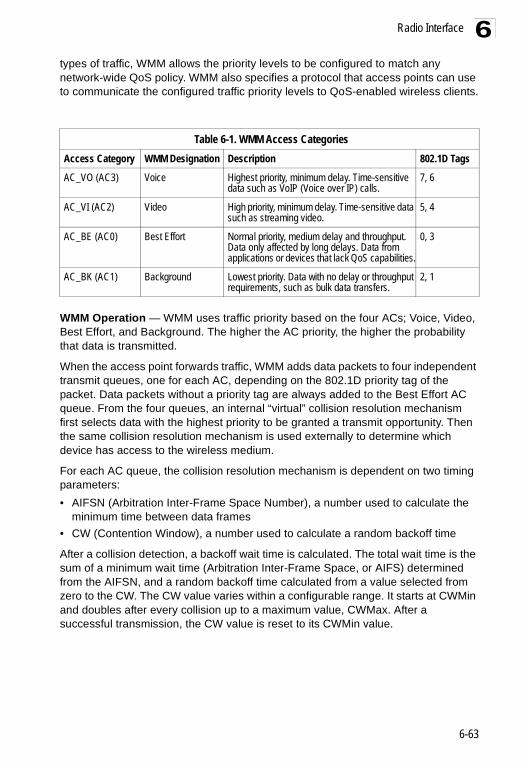
Radio Interface 6
types of traffic, WMM allows the priority levels to be configured to match any network-wide QoS policy. WMM also specifies a protocol that access points can use to communicate the configured traffic priority levels to QoS-enabled wireless clients.WMM Operation — WMM uses traffic priority based on the four ACs; Voice, Video, Best Effort, and Background. The higher the AC priority, the higher the probability that data is transmitted.
When the access point forwards traffic, WMM adds data packets to four independent transmit queues, one for each AC, depending on the 802.1D priority tag of the packet. Data packets without a priority tag are always added to the Best Effort AC queue. From the four queues, an internal “virtual” collision resolution mechanism first selects data with the highest priority to be granted a transmit opportunity. Then the same collision resolution mechanism is used externally to determine which device has access to the wireless medium.
For each AC queue, the collision resolution mechanism is dependent on two timing parameters:• AIFSN (Arbitration Inter-Frame Space Number), a number used to calculate the
minimum time between data frames• CW (Contention Window), a number used to calculate a random backoff time
After a collision detection, a backoff wait time is calculated. The total wait time is the sum of a minimum wait time (Arbitration Inter-Frame Space, or AIFS) determined from the AIFSN, and a random backoff time calculated from a value selected from zero to the CW. The CW value varies within a configurable range. It starts at CWMin and doubles after every collision up to a maximum value, CWMax. After a successful transmission, the CW value is reset to its CWMin value.
Table 6-1. WMM Access CategoriesAccess Category WMM Designation Description 802.1D Tags
AC_VO (AC3) Voice Highest priority, minimum delay. Time-sensitive data such as VoIP (Voice over IP) calls.
7, 6
AC_VI (AC2) Video High priority, minimum delay. Time-sensitive data such as streaming video.
5, 4
AC_BE (AC0) Best Effort Normal priority, medium delay and throughput. Data only affected by long delays. Data from applications or devices that lack QoS capabilities.
0, 3
AC_BK (AC1) Background Lowest priority. Data with no delay or throughput requirements, such as bulk data transfers.
2, 1
6-63

System Configuration6
Figure 6-1. WMM Backoff Wait Times
For high-priority traffic, the AIFSN and CW values are smaller. The smaller values equate to less backoff and wait time, and therefore more transmit opportunities.
To configure WMM, select the Radio Settings page, and scroll down to the WMM configuration settings.
AIFS Random Backoff
AIFS Random Backoff
CWMin CWMax
CWMin C
Tim
riority
riority
Minimum Wait Time Random Wait Time
Minimum Wait Time Random Wait Time
6-64

Radio Interface 6
WMM – Sets the WMM operational mode on the access point. When enabled, the parameters for each AC queue will be employed on the access point and QoS capabilities are advertised to WMM-enabled clients. (Default: Support)• Disable: WMM is disabled.• Support: WMM will be used for any associated device that supports this feature.Devices that do not support this feature may still associate with the access point.• Required: WMM must be supported on any device trying to associated with the
access point. Devices that do not support this feature will not be allowed to associate with the access point.
WMM Acknowledge Policy – By default, all wireless data transmissions require the sender to wait for an acknowledgement from the receiver. WMM allows the acknowledgement wait time to be turned off for each Access Category (AC). Although this increases data throughput, it can also result in a high number of errors when traffic levels are heavy. (Default: Acknowledge)
WMM BSS Parameters – These parameters apply to the wireless clients.WMM AP Parameters – These parameters apply to the access point.
• logCWMin (Minimum Contention Window) – The initial upper limit of the random backoff wait time before wireless medium access can be attempted. The initial wait time is a random value between zero and the CWMin value. Specify the CWMin value in the range 0-15 microseconds. Note that the CWMin value must be equal or less than the CWMax value.
• logCWMax (Maximum Contention Window) – The maximum upper limit of the random backoff wait time before wireless medium access can be attempted. The contention window is doubled after each detected collision up to the CWMax value. Specify the CWMax value in the range 0-15 microseconds. Note that the CWMax value must be greater or equal to the CWMin value.
• AIFS (Arbitration Inter-Frame Space) – The minimum amount of wait time before the next data transmission attempt. Specify the AIFS value in the range 0-15 microseconds.
• TXOP Limit (Transmit Opportunity Limit) – The maximum time an AC transmit queue has access to the wireless medium. When an AC queue is granted a transmit opportunity, it can transmit data for a time up to the TxOpLimit. This data bursting greatly improves the efficiency for high data-rate traffic. Specify a value in the range 0-65535 microseconds.
• Admission Control – The admission control mode for the access category. When enabled, clients are blocked from using the access category. (Default: Disabled)
Key Type – See “Wired Equivalent Privacy (WEP)” on page 6-75.
6-65

System Configuration6
CLI Commands for WMM – Enter interface wireless mode and type wmm required for clients that want to associate with the access point. The wmm-acknowledge-policy command is used to enable or disable a policy for each access category. The wmmparms command defines detailed WMM parameters.Enterprise AP(if-wireless a)#wmm required7-138Enterprise AP(if-wireless a)#wmm-acknowledge-policy 0 noack7-138Enterprise AP(if-wireless a)#wmmparams ap 0 4 6 3 1 17-139
6-66

Radio Interface 6
To view the current 802.11a radio settings for the VAP interface, use the show interface wireless a [0-3] command.SMC AP#show interface wireless a 0 7-113
Wireless Interface Information=============================================================--------------------Identification---------------------------Description : Enterprise 802.11a Access PointSSID : VAP_TEST_11A 0Turbo Mode : DISABLEDChannel : 36 (AUTO)Status : DISABLEDMAC Address : 00:12:cf:05:95:0c----------------802.11 Parameters---------------------------Transmit Power : FULL (16 dBm)Max Station Data Rate : 54MbpsMulticast Data Rate : 6MbpsFragmentation Threshold : 2346 bytesRTS Threshold : 2347 bytesBeacon Interval : 100 TUsAuthentication Timeout Interval : 60 MinsAssociation Timeout Interval : 30 MinsDTIM Interval : 1 beaconMaximum Association : 64 stationsMIC Mode : SoftwareSuper A : DisabledVLAN ID : 1----------------Security-------------------------------------Closed System : DisabledMulticast cipher : WEPWPA clients : TKIP and AESWPA Key Mgmt Mode : PRE SHARED KEYWPA PSK Key Type : PASSPHRASEEncryption : DISABLEDDefault Transmit Key : 1Common Static Keys : Key 1: EMPTY Key 2: EMPTY Key 3: EMPTY Key 4: EMPTYAuthentication Type : OPEN----------------802.1x---------------------------------------802.1x :Broadcast Key Refresh Rate : 30 minSession Key Refresh Rate : 30 min802.1x Session Timeout Value : 0 min----------------Antenna--------------------------------------Antenna Control method : DiversityAntenna ID : 0x0000(Default Antenna)Antenna Location : Indoor
6-67

System Configuration6
Radio Settings G (802.11g)The IEEE 802.11g standard operates within the 2.4 GHz band at up to 54 Mbps. Also note that because the IEEE 802.11g standard is an extension of the IEEE 802.11b standard, it allows clients with 802.11b wireless network cards to associate to an 802.11g access point.
First configure the radio settings that apply to the individual VAPs (Virtual Access Point) and the common radio settings that apply to all of the 802.11g interfaces. After you have configured the radio settings, go to the Security page under the 802.g Interface (See “Security” on page 6-70), enable the radio service for any of the VAP interfaces, and then set an SSID to identify the wireless network service provided by each VAP. Remember that only clients with the same SSID can associate with a VAP.
Note: You must first enable VAP interface 0 before the other interfaces can be enabled.
----------------Quality of Service---------------------------WMM Mode : SUPPORTEDWMM Acknowledge PolicyAC0(Best Effort) : AckAC1(Background) : AcknowledgeAC2(Video) : AcknowledgeAC3(Voice) : AcknowledgeWMM BSS ParametersAC0(Best Effort) : logCwMin: 4 logCwMax: 10 AIFSN: 3 Admission Control: No TXOP Limit: 0.000 msAC1(Background) : logCwMin: 4 logCwMax: 10 AIFSN: 7 Admission Control: No TXOP Limit: 0.000 msAC2(Video) : logCwMin: 3 logCwMax: 4 AIFSN: 2 Admission Control: No TXOP Limit: 3.008 msAC3(Voice) : logCwMin: 2 logCwMax: 3 AIFSN: 2 Admission Control: No TXOP Limit: 1.504 msWMM AP ParametersAC0(Best Effort) : logCwMin: 4 logCwMax: 6 AIFSN: 3 Admission Control: No TXOP Limit: 0.000 msAC1(Background) : logCwMin: 4 logCwMax: 10 AIFSN: 7 Admission Control: No TXOP Limit: 0.000 msAC2(Video) : logCwMin: 3 logCwMax: 4 AIFSN: 1 Admission Control: No TXOP Limit: 3.008 msAC3(Voice) : logCwMin: 2 logCwMax: 3 AIFSN: 1 Admission Control: No TXOP Limit: 1.504 ms=============================================================SMC AP#
6-68

Radio Interface 6
Most of the 802.11g commands are identical to those used by the 802.11a interface. For information on the these commands, refer to the following sections:• “Configuring VAP Radio Settings” on page 6-53• “Configuring Rogue AP Detection” on page 6-55• “Configuring Common Radio Settings” on page 6-58• “Configuring Wi-Fi Multimedia” on page 6-62
Only the radio settings specific to the 802.11g interface are included in this section. To configure the 802.11g radio settings, select the Radio Settings page.
Radio Mode – Selects the operating mode for the 802.11g wireless interface. (Default: 802.11b+g)• 802.11b+g: Both 802.11b and 802.11g clients can communicate with the access
point (up to 54 Mbps).• 802.11b only: Both 802.11b and 802.11g clients can communicate with the access
point, but 802.11g clients can only transfer data at 802.11b standard rates (up to 11 Mbps).
• 802.11g only: Only 802.11g clients can communicate with the access point (up to 54 Mbps).
Radio Channel – The radio channel that the access point uses to communicate with wireless clients. When multiple access points are deployed in the same area, set the channel on neighboring access points at least five channels apart to avoid interference with each other. For example, in the United States you can deploy up to three access points in the same area (e.g., channels 1, 6, 11). Also note that the channel for wireless clients is automatically set to the same as that used by the access point to which it is linked. (Range: 1-11; Default: 1)
6-69

System Configuration6
Auto Channel Select – Enables the access point to automatically select an unoccupied radio channel. (Default: Enabled)Maximum Station Data Rate – The maximum data rate at which the access point transmits unicast packets on the wireless interface. The maximum transmission distance is affected by the data rate. The lower the data rate, the longer the transmission distance. (Default: 54 Mbps)
Super G – The Atheros proprietary Super G performance enhancements are supported by the access point. These enhancements include bursting, compression, fast frames and dynamic turbo. Maximum throughput ranges between 40 to 60 Mbps for connections to Atheros-compatible clients. (Default: Disabled)
Preamble – Sets the length of the signal preamble that is used at the start of a data transmission. (Default: Long)
• Long: Sets the preamble to long (192 microseconds). Using a long preamble ensures the access point can support all 802.11b and 802.11g clients.
• Short or Long: Sets the preamble according to the capability of clients that are currently asscociated. Uses a short preamble (96 microseconds) if all associated clients can support it, otherwise a long preamble is used. The access point can increase data throughput when using a short preamble, but will only use a short preamble if it determines that all associated clients support it.
CLI Commands for the 802.11g Wireless Interface – From the global configuration mode, enter the interface wireless g command to access the 802.11g radio interface. The 802.11g radio can be forced to an 802.11g-only, 802.11b-only, or mixed 802.11b/g operating mode using the radio-mode command. You should set the desired operating mode before configuring channel settings (the default is mixed 802.11b/g operation). Select a radio channel or set selection to Auto using the channel command. Set any other radio settings as required before enabling the VAP interface (with the no shutdown command). To view the current 802.11g radio settings for the VAP interface, use the show interface wireless g [0~3] command as shown on 7-97.
SecurityThe access point is configured by default as an “open system,” which broadcasts a beacon signal including the configured SSID. Wireless clients with an SSID setting of “any” can read the SSID from the beacon and automatically set their SSID to allow immediate connection to the nearest access point.
SMC AP(config)#interface wireless g 7-90Enter Wireless configuration commands, one per line.Enterprise AP(if-wireless g)#radio-mode g 7-101SMC AP(if-wireless g)#channel auto 7-100SMC AP(if-wireless a)#transmit-power full 7-100SMC AP(if-wireless a)#super-g 7-108Enterprise AP(if-wireless g)#preamble short 7-102SMC AP(if-wireless g)#
6-70

Radio Interface 6
To improve wireless network security, you have to implement two main functions:• Authentication: It must be verified that clients attempting to connect to the networkare authorized users.• Traffic Encryption: Data passing between the access point and clients must be
protected from interception and eavesdropping.
For a more secure network, the access point can implement one or a combination of the following security mechanisms:• Wired Equivalent Privacy (WEP) page 6-71• IEEE 802.1X page 6-86• Wireless MAC address filtering page 6-13• Wi-Fi Protected Access (WPA or WPA2) page 6-81
Both WEP and WPA security settings are configurable separately for each virtual access point (VAP) interface. MAC address filtering, and RADIUS server settings are global and apply to all VAP interfaces.
The security mechanisms that may be employed depend on the level of security required, the network and management resources available, and the software support provided on wireless clients.
A summary of wireless security considerations is listed in the following table.
Table 6-2. Wireless Security ConsiderationsSecurity Mechanism
Client Support Implementation Considerations
WEP Built-in support on all 802.11a and 802.11g devices
• Provides only weak security• Requires manual key management
WEP over 802.1X Requires 802.1X client support in system or by add-in software(support provided in Windows 2000 SP3 or later and Windows XP)
• Provides dynamic key rotation for improved WEP security
• Requires configured RADIUS server• 802.1X EAP type may require management of
digital certificates for clients and server
MAC Address Filtering
Uses the MAC address of client network card
• Provides only weak user authentication• Management of authorized MAC addresses• Can be combined with other methods for improved
security• Optionally configured RADIUS server
WPA over 802.1X Mode
Requires WPA-enabled system and network card driver(native support provided in Windows XP)
• Provides robust security in WPA-only mode (i.e., WPA clients only)
• Offers support for legacy WEP clients, but with increased security risk (i.e., WEP authentication keys disabled)
• Requires configured RADIUS server• 802.1X EAP type may require management of
digital certificates for clients and server
6-71

System Configuration6
Note: You must enable data encryption through the web or CLI in order to enable all types of encryption (WEP, TKIP, or AES) in the access point.
The access point can simultaneously support clients using various different security mechanisms. The configuration for these security combinations are outlined in the following table. Note that MAC address authentication can be configured independently to work with all security mechanisms and is indicated separately in the table. Required RADIUS server support is also listed.
WPA PSK Mode Requires WPA-enabled system and network card driver(native support provided in Windows XP)
• Provides good security in small networks• Requires manual management of pre-shared key
WPA2 with 802.1X Requires WPA-enabled system and network card driver (native support provided in Windows XP)
• Provides the strongest security in WPA2-only mode
• Provides robust security in mixed mode for WPA and WPA2 clients
• Offers fast roaming for time-sensitive client applications
• Requires configured RADIUS server• 802.1X EAP type may require management of
digital certificates for clients and server• Clients may require hardware upgrade to be WPA2
compliant
WPA2 PSK Mode Requires WPA-enabled system and network card driver (native support provided in Windows XP)
• Provides robust security in small networks• Requires manual management of pre-shared key• Clients may require hardware upgrade to be WPA2
compliant
Table 6-3. Security CombinationsClient SecurityCombination
Configuration Summarya MACAuthenticationb
RADIUSServer
No encryption and no authentication
Interface Detail Settings:Authentication: Open SystemEncryption: Disable802.1x: Disable
Local, RADIUS, or Disabled
Yes3
Static WEP only (with or without shared key authentication)
Enter 1 to 4 WEP keysSelect a WEP transmit key for the interfaceInterface Detail Settings:Authentication: Shared Key or Open SystemEncryption: Enable802.1x: Disable
Local, RADIUS, or Disabled
Yesc
Table 6-2. Wireless Security ConsiderationsSecurity Mechanism
Client Support Implementation Considerations
6-72

Radio Interface 6
Dynamic WEP (802.1x) only
Interface Detail Settings:Authentication: Open SystemEncryption: Enable802.1x: RequiredSet 802.1x key refresh and reauthentication rates
Local, RADIUS, or Disabled
Yesc
802.1x WPA only Interface Detail Settings:Authentication: WPAEncryption: EnableWPA Configuration: RequiredCipher Suite: TKIP802.1x: RequiredSet 802.1x key refresh and reauthentication rates
Local only Yes
WPA Pre-Shared Key only
Interface Detail Settings:Authentication: WPA-PSKEncryption: EnableWPA Configuration: RequiredCipher Configuration: TKIP802.1x: DisableWPA Pre-shared Key Type: Hexadicmal or AlphanumericEnter a WPA Pre-shared key
Local only No
Static and dynamic (802.1x) WEP keys
Enter 1 to 4 WEP keysSelect a WEP transmit keyInterface Detail Settings:Authentication: Open SystemEncryption: Enable802.1x: SupportedSet 802.1x key refresh and reauthentication rates
Local, RADIUS, or Disabled
Yes
Dynamic WEP and 802.1x WPA
Interface Detail Settings:Authentication: WPAEncryption: EnableWPA Configuration: SupportedCipher Suite: WEP802.1x: RequiredSet 802.1x key refresh and reauthentication rates
Local or Disabled Yes
Static and dynamic (802.1x) WEP keys and 802.1x WPA
Enter 1 to 4 WEP keysSelect a WEP transmit keyInterface Detail Settings:Authentication: WPAEncryption: EnableWPA Configuration: SupportedCipher Suite: WEP802.1x: SupportedSet 802.1x key refresh and reauthentication rates
Local or Disabled Yes
Table 6-3. Security CombinationsClient SecurityCombination
Configuration Summarya MACAuthenticationb
RADIUSServer
6-73

System Configuration6
Note: If you choose to configure RADIUS MAC authentication together with 802.1X, the RADIUS MAC address authentication occurs prior to 802.1X authentication. Only when RADIUS MAC authentication succeeds is 802.1X authentication performed. When RADIUS MAC authentication fails, 802.1X authentication is not performed.
802.1x WPA2 only Interface Detail Settings:Authentication: WPA2Encryption: EnableWPA Configuration: RequiredCipher Suite: AES-CCMP802.1x: RequiredSet 802.1x key refresh and reauthentication rates
Local or Disabled Yes
WPA2 Pre-Shared Key only
Interface Detail Settings:Authentication: WPA2-PSKEncryption: EnableWPA Configuraton: RequiredCipher Suite: AES-CCMP802.1x: DisableWPA Pre-shared Key Type: Hexadicmal or AlphanumericEnter a WPA Pre-shared key
Local or Disabled No
802.1x WPA-WPA2 Mixed Mode
Interface Detail Settings:Authentication: WPA-WPA2-mixedEncryption: EnableWPA Configuration: RequiredCipher Suite: TKIP802.1x: RequiredSet 802.1x key refresh and reauthentication rates
Local or Disabled Yes
WPA-WPA2 Mixed Mode Pre-Shared Key
Interface Detail Settings:Authentication: WPA-WPA2-PSK-mixedEncryption: EnableWPA Configuration: RequiredCipher Suite: TKIP802.1x: DisableWPA Pre-shared Key Type: Hexadicmal or AlphanumericEnter a WPA Pre-shared key
Local or Disabled No
a. The configuration summary does not include the set up for MAC authentication (see page 4-15) or RADIUS server (see page 2-9).
b. The configuration of RADIUS MAC authentication together with 802.1x WPA or WPA Pre-shared Key is not supported.
c. RADIUS server required only when RADIUS MAC authentication is configured.
Table 6-3. Security CombinationsClient SecurityCombination
Configuration Summarya MACAuthenticationb
RADIUSServer
6-74

Radio Interface 6
Enabling the VAPsBefore enabling the Virtual Access Point (VAP) radio interfaces, first configure all of the relevant raido settings (see “Radio Settings A (802.11a)” on page 6-53 or “Radio Settings G (802.11g)” on page 6-68.)After you have configured the radio settings, select Security under Radio A or Radio G, set an SSID to identify the wireless network service provided by each VAP you want to use, and then click Apply to save your settings.
Before enabling the radio service for any VAP, first configure the WEP, WPA, and 802.1X security settings described in the following sections. After you have finished configuring the security settings, return to the main Security page shown below, start the required VAP interfaces by clicking the Enable checkbox, and then click Apply.
Enable – Enables radio communications on the VAP interface. (Default: Disabled)
Note: You must first enable VAP interface 0 before you can enable other VAP interfaces.
SSID – The name of the basic service set provided by a VAP interface. Clients that want to connect to the network through the access point must set their SSID to the same as that of an access point VAP interface. (Default: SMC_VAP_11A (0-3); Range: 1-32 characters)
Wired Equivalent Privacy (WEP) WEP provides a basic level of security, preventing unauthorized access to the network, and encrypting data transmitted between wireless clients and the access point. WEP uses static shared keys (fixed-length hexadecimal or alphanumeric strings) that are manually distributed to all clients that want to use the network.
WEP is the security protocol initially specified in the IEEE 802.11 standard for wireless communications. Unfortunately, WEP has been found to be seriously flawed and cannot be recommended for a high level of network security. For more robust wireless security, the access point provides Wi-Fi Protected Access (WPA) for improved data encryption and user authentication.
6-75
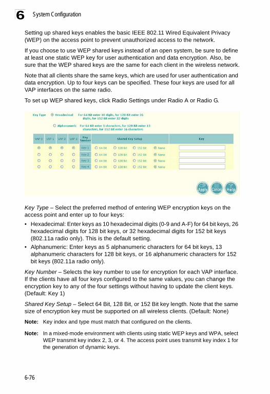
System Configuration6
Setting up shared keys enables the basic IEEE 802.11 Wired Equivalent Privacy (WEP) on the access point to prevent unauthorized access to the network.If you choose to use WEP shared keys instead of an open system, be sure to define at least one static WEP key for user authentication and data encryption. Also, be sure that the WEP shared keys are the same for each client in the wireless network.
Note that all clients share the same keys, which are used for user authentication and data encryption. Up to four keys can be specified. These four keys are used for all VAP interfaces on the same radio.
To set up WEP shared keys, click Radio Settings under Radio A or Radio G.
Key Type – Select the preferred method of entering WEP encryption keys on the access point and enter up to four keys:• Hexadecimal: Enter keys as 10 hexadecimal digits (0-9 and A-F) for 64 bit keys, 26
hexadecimal digits for 128 bit keys, or 32 hexadecimal digits for 152 bit keys (802.11a radio only). This is the default setting.
• Alphanumeric: Enter keys as 5 alphanumeric characters for 64 bit keys, 13 alphanumeric characters for 128 bit keys, or 16 alphanumeric characters for 152 bit keys (802.11a radio only).
Key Number – Selects the key number to use for encryption for each VAP interface. If the clients have all four keys configured to the same values, you can change the encryption key to any of the four settings without having to update the client keys. (Default: Key 1)
Shared Key Setup – Select 64 Bit, 128 Bit, or 152 Bit key length. Note that the same size of encryption key must be supported on all wireless clients. (Default: None)
Note: Key index and type must match that configured on the clients.
Note: In a mixed-mode environment with clients using static WEP keys and WPA, select WEP transmit key index 2, 3, or 4. The access point uses transmit key index 1 for the generation of dynamic keys.
6-76

Radio Interface 6
To enable WEP shared keys for a VAP interface, click Security under Radio A or Radio G. Then, select the VAP interface that will use WEP keys by clicking More, and configure the Authentication Type Setup and Encryption fields.Authentication Type Setup – Sets the access point to communicate as an open system that accepts network access attempts from any client, or with clients using pre-configured static shared keys. (Default: Open System)
• Open System: If you don’t set up any other security mechanism on the access point, the network has no protection and is open to all users. This is the default setting.
• Shared Key: Sets the access point to use WEP shared keys. If this option is selected, you must configure at least one key on the access point and all clients.
Note: To use 802.1X on wireless clients requires a network card driver and 802.1X client software that supports the EAP authentication type that you want to use. Windows 2000 SP3 or later and Windows XP provide 802.1X client support. Windows XP also provides native WPA support. Other systems require additional client software to support 802.1X and WPA.
Encryption – Enable or disable the access point to use data encryption (WEP, TKIP, or AES). If this option is selected when using static WEP keys, you must configure at least one key on the access point and all clients. (Default: Disabled)
Note: You must enable data encryption through the web or CLI in order to enable all types of encryption (WEP, TKIP, or AES) in the access point.
CLI Commands for WEP Shared Key Security – To enable WEP shared key security for the 802.11g interface, use the interface wireless g command from the CLI configuration mode to access the interface mode for the 802.11g radio. First use the
6-77

System Configuration6
key command to define up to four WEP keys that can be used for all VAP interfaces on the radio. Then use the vap command to access each VAP interface to configure other security settings.From the VAP interface configuration mode, use the auth command to enable WEP shared-key authentication, which enables encryption automatically. Then set one key as the transmit key for the VAP interface using the transmit-key command. To view the current security settings, use the show interface wireless g [0-3] command from the Exec mode.
6-78

Radio Interface 6
SMC AP(config)#interface wireless g 7-90Enter Wireless configuration commands, one per line.SMC AP(if-wireless g)#key 1 128 ascii abcdeabcdeabc 7-124SMC AP(if-wireless g)#vap 0 7-97SMC AP(if-wireless g: VAP[0])#auth shared-key 7-124Data Encryption is set to enabled.Remember to set the share key using "key" command.SMC AP(if-wireless g: VAP[0])#transmit-key 1 7-125SMC AP(if-wireless g: VAP[0])#exitSMC AP#show interface wireless g 0 7-113Wireless Interface Information========================================================================----------------Identification------------------------------------------Description : Enterprise 802.11g Access PointSSID : VAP_TEST_11G 0Channel : 11 (AUTO)Status : DISABLEDMAC Address : 00:12:cf:05:95:08----------------802.11 Parameters----------------------------------------Radio Mode : b & g mixed modeTransmit Power : FULL (5 dBm)Max Station Data Rate : 54MbpsMulticast Data Rate : 5.5MbpsFragmentation Threshold : 2346 bytesRTS Threshold : 2347 bytesBeacon Interval : 100 TUsAuthentication Timeout Interval : 60 MinsAssociation Timeout Interval : 30 MinsDTIM Interval : 1 beaconPreamble Length : SHORT-OR-LONGMaximum Association : 64 stationsMIC Mode : SoftwareSuper G : DisabledVLAN ID : 1----------------Security------------------------------------------------Closed System : DisabledMulticast cipher : WEPUnicast cipher : TKIP and AESWPA clients : DISABLEDWPA Key Mgmt Mode : PRE SHARED KEYWPA PSK Key Type : PASSPHRASEWPA PSK Key : EMPTYPMKSA Lifetime : 720 minutesEncryption : ENABLEDDefault Transmit Key : 1Common Static Keys : Key 1: EMPTY Key 2: EMPTY Key 3: EMPTY Key 4: EMPTYPre-Authentication : DISABLEDAuthentication Type : SHARED----------------802.1x--------------------------------------------------802.1x : DISABLEDBroadcast Key Refresh Rate : 30 minSession Key Refresh Rate : 30 min802.1x Session Timeout Value : 0 min
6-79

System Configuration6
CLI Commands for WEP over 802.1X Security – Use the vap command to access each VAP interface to configure the security settings. First set 802.1X to required using the 802.1x command and set the 802.1X key refresh rates. Then, use the auth command to select open system authentication and the encryption command
----------------Antenna-------------------------------------------------Antenna Control method : DiversityAntenna ID : 0x0000(Default Antenna)Antenna Location : Indoor----------------Quality of Service---------------------------------------WMM Mode : SUPPORTEDWMM Acknowledge PolicyAC0(Best Effort) : AcknowledgeAC1(Background) : AcknowledgeAC2(Video) : AcknowledgeAC3(Voice) : AcknowledgeWMM BSS ParametersAC0(Best Effort) : logCwMin: 4 logCwMax: 10 AIFSN: 3 Admission Control: No TXOP Limit: 0.000 msAC1(Background) : logCwMin: 4 logCwMax: 10 AIFSN: 7 Admission Control: No TXOP Limit: 0.000 msAC2(Video) : logCwMin: 3 logCwMax: 4 AIFSN: 2 Admission Control: No TXOP Limit: 3.008 msAC3(Voice) : logCwMin: 2 logCwMax: 3 AIFSN: 2 Admission Control: No TXOP Limit: 1.504 msWMM AP ParametersAC0(Best Effort) : logCwMin: 4 logCwMax: 6 AIFSN: 3 Admission Control: No TXOP Limit: 0.000 msAC1(Background) : logCwMin: 4 logCwMax: 10 AIFSN: 7 Admission Control: No TXOP Limit: 0.000 msAC2(Video) : logCwMin: 3 logCwMax: 4 AIFSN: 1 Admission Control: No TXOP Limit: 3.008 msAC3(Voice) : logCwMin: 2 logCwMax: 3 AIFSN: 1 Admission Control: No TXOP Limit: 1.504 ms========================================================================SMC AP#
6-80

Radio Interface 6
to enable data encryption. To view the current security settings, use the show interface wireless a [0-3] or show interface wireless g [0-3] command (not shown in example).Wi-Fi Protected Access (WPA)WPA employs a combination of several technologies to provide an enhanced security solution for 802.11 wireless networks.
The access point supports the following WPA components and features:
IEEE 802.1X and the Extensible Authentication Protocol (EAP): WPA employs 802.1X as its basic framework for user authentication and dynamic key management. The 802.1X client and RADIUS server should use an appropriate EAP type—such as EAP-TLS (Transport Layer Security), EAP-TTLS (Tunneled TLS), or PEAP (Protected EAP)—for strongest authentication. Working together, these protocols provide “mutual authentication” between a client, the access point, and a RADIUS server that prevents users from accidentally joining a rogue network. Only when a RADIUS server has authenticated a user’s credentials will encryption keys be sent to the access point and client.
Note: To implement WPA on wireless clients requires a WPA-enabled network card driver and 802.1X client software that supports the EAP authentication type that you want to use. Windows XP provides native WPA support, other systems require additional software.
Temporal Key Integrity Protocol (TKIP): WPA specifies TKIP as the data encryption method to replace WEP. TKIP avoids the problems of WEP static keys by dynamically changing data encryption keys. Basically, TKIP starts with a master (temporal) key for each user session and then mathematically generates other keys to encrypt each data packet. TKIP provides further data encryption enhancements by including a message integrity check for each packet and a re-keying mechanism, which periodically changes the master key.
WPA Pre-Shared Key Mode (WPA-PSK, WPA2-PSK): For enterprise deployment, WPA requires a RADIUS authentication server to be configured on the wired network. However, for small office networks that may not have the resources to configure and maintain a RADIUS server, WPA provides a simple operating mode that uses just a pre-shared password for network access. The Pre-Shared Key mode uses a common password for user authentication that is manually entered on
SMC AP(if-wireless g)#vap 0SMC AP(if-wireless g: VAP[0])#802.1X required 7-66SMC AP(if-wireless g: VAP[0])#802.1X
broadcast-key-refresh-rate 5 7-67SMC AP(if-wireless g: VAP[0])#802.1X session-key-refresh-rate 5 7-68SMC AP(if-wireless g: VAP[0])#802.1X session-timeout 300 7-68SMC AP(if-wireless g: VAP[0])#auth open-system 7-124SMC AP(if-wireless g: VAP[0])#encryption 7-123SMC AP(if-wireless g: VAP[0])#
6-81

System Configuration6
the access point and all wireless clients. The PSK mode uses the same TKIP packet encryption and key management as WPA in the enterprise, providing a robust and manageable alternative for small networks.Mixed WPA and WEP Client Support: WPA enables the access point to indicate its supported encryption and authentication mechanisms to clients using its beacon signal. WPA-compatible clients can likewise respond to indicate their WPA support. This enables the access point to determine which clients are using WPA security and which are using legacy WEP. The access point uses TKIP unicast data encryption keys for WPA clients and WEP unicast keys for WEP clients. The global encryption key for multicast and broadcast traffic must be the same for all clients, therefore it restricts encryption to a WEP key.
When access is opened to both WPA and WEP clients, no authentication is provided for the WEP clients through shared keys. To support authentication for WEP clients in this mixed mode configuration, you can use either MAC authentication or 802.1X authentication.
WPA2 – WPA was introduced as an interim solution for the vulnerability of WEP pending the ratification of the IEEE 802.11i wireless security standard. In effect, the WPA security features are a subset of the 802.11i standard. WPA2 includes the now ratified 802.11i standard, but also offers backward compatibility with WPA. Therefore, WPA2 includes the same 802.1X and PSK modes of operation and support for TKIP encryption. The main differences and enhancements in WPA2 can be summarized as follows:
• Advanced Encryption Standard (AES): WPA2 uses AES Counter-Mode encryption with Cipher Block Chaining Message Authentication Code (CBC-MAC) for message integrity. The AES Counter-Mode/CBCMAC Protocol (AES-CCMP) provides extremely robust data confidentiality using a 128-bit key. The AES-CCMP encryption cipher is specified as a standard requirement for WPA2. However, the computational intensive operations of AES-CCMP requires hardware support on client devices. Therefore to implement WPA2 in the network, wireless clients must be upgraded to WPA2-compliant hardware.
• WPA2 Mixed-Mode: WPA2 defines a transitional mode of operation for networks moving from WPA security to WPA2. WPA2 Mixed Mode allows both WPA and WPA2 clients to associate to a common SSID interface. In mixed mode, the unicast encryption cipher (TKIP or AES-CCMP) is negotiated for each client. The access point advertises its supported encryption ciphers in beacon frames and probe responses. WPA and WPA2 clients select the cipher they support and return the choice in the association request to the access point. For mixed-mode operation, the cipher used for broadcast frames is always TKIP. WEP encryption is not allowed.
• Key Caching: WPA2 provides fast roaming for authenticated clients by retaining keys and other security information in a cache, so that if a client roams away from an access point and then returns, re-authentication is not required. When a WPA2 client is first authenticated, it receives a Pairwise Master Key (PMK) that is used to generate other keys for unicast data encryption. This key and other client
6-82

Radio Interface 6
information form a Security Association that the access point names and holds in a cache.• Preauthentication: Each time a client roams to another access point it has to be fully re-authenticated. This authentication process is time consuming and can disrupt applications running over the network. WPA2 includes a mechanism, known as pre-authentication, that allows clients to roam to a new access point and be quickly associated. The first time a client is authenticated to a wireless network it has to be fully authenticated. When the client is about to roam to another access point in the network, the access point sends pre-authentication messages to the new access point that include the client’s security association information. Then when the client sends an association request to the new access point, the client is known to be already authenticated, so it proceeds directly to key exchange and association.
To configure WPA, click Security under Radio A or Radio G. Select one of the VAP interfaces by clicking More. Select one of the WPA options in the Authentication Setup table, and then configure the parameters displayed beneath the table.
6-83

System Configuration6
The WPA configuration parameters are described below:Encryption – You must enable data encryption in order to enable all types of encryption (WEP, TKIP, or AES) in the access point.
Pre-Authentication – When using WPA2 over 802.1X, pre-authentication can be enabled, which allows clients to roam to a new access point and be quickly associated without performing full 802.1X authentication. (Default: Disabled)
Authentication Setup – To use WPA or WPA2, set the access point to one of the following options. If a WPA/WPA2 mode that operates over 802.1X is selected (WPA, WPA2, or WPA-WPA2-mixed), the 802.1X settings and RADIUS server details need to be configured. Be sure you have also configured a RADIUS server on the network before enabling authentication. If a WPA/WPA2 Pre-shared Key mode is selected (WPA-PSK, WPA2-PSK, or WPA-WPA2 PSK-Mixed), be sure to specify the key string. • WPA: Clients using WPA over 802.1X are accepted for authentication.• WPA-PSK: Clients using WPA with a Pre-shared Key are accepted for
authentication.• WPA2: Clients using WPA2 over 802.1X are accepted for authentication.• WPA2-PSK: Clients using WPA2 with a Pre-shared Key are accepted for
authentication.• WPA-WPA2-mixed: Clients using WPA or WPA2 over 802.1X are accepted for
authentication.• WPA-WPA2-PSK-mixed: Clients using WPA or WPA2 with a Pre-shared Key are
accepted for authentication.
WPA Configuration – Each VAP interface can be configured to allow only WPA-enabled clients to access the network (Required), or to allow access to both WPA and WEP clients (Supported). (Default: Required)
Cipher Suite – Selects an encryption method for the global key used for multicast and broadcast traffic, which is supported by all wireless clients.
• WEP: WEP is used as the multicast encryption cipher. You should select WEP only when both WPA and WEP clients are supported.
• TKIP: TKIP is used as the multicast encryption cipher.• AES-CCMP: AES-CCMP is used as the multicast encryption cipher. AES-CCMP
is the standard encryption cipher required for WPA2.
WPA Pre-Shared Key Type – If the WPA or WPA2 pre-shared-key mode is used, all wireless clients must be configured with the same key to communicate with the access point.• Hexadecimal – Enter a key as a string of 64 hexadecimal numbers.• Alphanumeric – Enter a key as an easy-to-remember form of letters and numbers.
The string must be from 8 to 63 characters, which can include spaces.
6-84

Radio Interface 6
The configuration settings for WPA are summarized below:CLI Commands for WPA Using Pre-shared Key Security – From the VAP interface configuration mode, use the auth wpa-psk required command to enable WPA Pre-shared Key security. To enter a key value, use the wpa-pre-shared-key command to specify a hexadecimal or alphanumeric key. To view the current security settings, use the show interface wireless a [0-3] or show interface wireless g [0-3] command (not shown in example).
Table 6-4. WPA Configuration SettingsWPA and WPA2 pre-shared key only WPA and WPA2 over 802.1X
Encryption: EnabledAuthentication Setup: WPA-PSK, WPA2-PSK, or WPA-WPA2-mixedCipher Suite: WEP/TKIP/AES-CCMPWPA Pre-shared Key Type: Hex/ASCII
Encryption: EnabledAuthentication Setup: WPA, WPA2, WPA-WPA2-mixedCipher Suite: WEP/TKIP/AES-CCMP(requires RADIUS server to be specified)
1: You must enable data encryption in order to enable all types of encryption in the access point. 2: Select TKIP when any WPA clients do not support AES. Select AES only if all clients support AES.
SMC AP(config)#interface wireless g 7-90Enter Wireless configuration commands, one per line.Enterprise AP(if-wireless g)#vap 0SMC AP(if-wireless g: VAP[0])#wpa-pre-shared-key passphrase-key agoodsecret 7-128SMC AP(if-wireless g: VAP[0])#auth wpa-psk requiredData Encryption is set to Enabled.WPA2 Clients Mode is set to Disabled.WPA Clients Mode is set to Required.WPA Multicast Cipher is set to TKIP.WPA Unicast Cipher can accept TKIP only.WPA Authentication is set to Pre-Shared Key.SMC AP(if-wireless g: VAP[0])#
6-85

System Configuration6
CLI Commands for WPA Over 802.1X Security – From the VAP interface configuration mode, use the auth wpa required command to select WPA over 802.1X security. Then set the 802.1X key refresh rates. To view the current security settings, use the show interface wireless a [0-3] or show interface wireless g [0-3] command (not shown in example).Configuring 802.1XIEEE 802.1X is a standard framework for network access control that uses a central RADIUS server for user authentication. This control feature prevents unauthorized access to the network by requiring an 802.1X client application to submit user credentials for authentication. The 802.1X standard uses the Extensible Authentication Protocol (EAP) to pass user credentials (either digital certificates, user names and passwords, or other) from the client to the RADIUS server. Client authentication is then verified on the RADIUS server before the access point grants client access to the network.
The 802.1X EAP packets are also used to pass dynamic unicast session keys and static broadcast keys to wireless clients. Session keys are unique to each client and are used to encrypt and correlate traffic passing between a specific client and the access point. You can also enable broadcast key rotation, so the access point provides a dynamic broadcast key and changes it at a specified interval.
SMC AP(config)#interface wireless g 7-90Enter Wireless configuration commands, one per line.SMC AP(if-wireless g)#vap 0SMC AP(if-wireless g: VAP[0])#auth wpa requiredData Encryption is set to Enabled.WPA2 Clients mode is set to Disabled.WPA Clients Mode is set to Required.WPA Multicast Cipher is set to TKIP.WPA Unicast Cipher can accept TKIP only.WPA Authentication is set to 802.1X Required. SMC AP(if-wireless g: VAP[0])#802.1X broadcast-key-refresh-rate 5SMC AP(if-wireless g: VAP[0])#802.1X
session-key-refresh-rate 5 7-67SMC AP(if-wireless g: VAP[0])#802.1X session-timeout 300 7-68SMC AP(if-wireless g: VAP[0])#
6-86

Radio Interface 6
Open the Security page, and click More for one of the VAP interfaces.You can enable 802.1X as optionally supported or as required to enhance the security of the wireless network. (Default: Disable)
• Disable: The access point does not support 802.1X authentication for any wireless client. After successful wireless association with the access point, each client is allowed to access the network.
• Supported: The access point supports 802.1X authentication only for clients initiating the 802.1X authentication process (i.e., the access point does not initiate 802.1X authentication). For clients initiating 802.1X, only those successfully authenticated are allowed to access the network. For those clients not initiating 802.1X, access to the network is allowed after successful wireless association with the access point. The 802.1X supported mode allows access for clients not using WPA or WPA2 security.
• Required: The access point enforces 802.1X authentication for all associated wireless clients. If 802.1X authentication is not initiated by a client, the access point will initiate authentication. Only those clients successfully authenticated with 802.1X are allowed to access the network.
Note: If 802.1X is enabled on the access point, then RADIUS setup must be completed (See “RADIUS” on page 6-7).
When 802.1X is enabled, the broadcast and session key rotation intervals can also be configured.• Broadcast Key Refresh Rate: Sets the interval at which the broadcast keys are
refreshed for stations using 802.1X dynamic keying. (Range: 0-1440 minutes; Default: 0 means disabled)
• Session Key Refresh Rate: The interval at which the access point refreshes unicast session keys for associated clients. (Range: 0-1440 minutes; Default: 0 means disabled)
6-87

System Configuration6
• 802.1X Reauthentication Refresh Rate: The time period after which a connectedclient must be re-authenticated. During the re-authentication process of verifying the client’s credentials on the RADIUS server, the client remains connected the network. Only if re-authentication fails is network access blocked. (Range: 0-65535 seconds; Default: 0 means disabled)
CLI Commands for 802.1X Authentication – Use the 802.1X supported command from the VAP interface mode to enable 802.1X authentication. Set the session and broadcast key refresh rate, and the re-authentication timeout. To display the current settings, use the show interface wireless command from the Exec mode (not shown in the example).
Status Information
The Status page includes information on the following items:
Access Point StatusThe AP Status window displays basic system configuration settings, as well as the settings for the wireless interface.
SMC AP(if-wireless g: VAP[0])#802.1X supported 7-66SMC AP(if-wireless g: VAP[0])#802.1X broadcast-key-refresh-rate 5 7-67SMC AP(if-wireless g: VAP[0])#802.1X
session-key-refresh-rate 5 7-68SMC AP(if-wireless g: VAP[0])#802.1X session-timeout 300 7-68SMC AP#
Menu Description Page
AP Status Displays configuration settings for the basic system and the wireless interface
6-88
Station Status Shows the wireless clients currently associated with the access point
6-91
Event Logs Shows log messages stored in memory 6-93
6-88

Status Information 6
AP System Configuration – The AP System Configuration table displays the basic system configuration settings:
• System Up Time: Length of time the management agent has been up.• Ethernet MAC: The physical layer address for the Ethernet port.• Radio A MAC: The physical layer address for the 802.11a interface.• Radio G MAC: The physical layer address for the 802.11b/g interface.• System Name: Name assigned to this system.• System Contact: Administrator responsible for the system.• IP Address: IP address of the management interface for this device.• IP Default Gateway: IP address of the gateway router between this device and
management stations that exist on other network segments.• HTTP Server: Shows if management access via HTTP is enabled.• HTTP Server Port: Shows the TCP port used by the HTTP interface.• Software Version: Shows the software version number.• Bootrom Version: Show the bootrom version number.• Hardware Version: Shows the hardware version number.
6-89

System Configuration6
AP Wireless Configuration – The AP Wireless Configuration tables display the radio and VAP interface settings listed below. Note that Interface Wireless A refers to the 802.11a radio and Interface Wireless G refers the 802.11b/g radio.• SSID: The service set identifier for the VAP interface.• Radio Channel: The radio channel through which the access point communicateswith wireless clients.• Encryption: The key size used for data encryption.• Authentication Type: Shows the type of authentication used.• 802.1X: Shows if IEEE 802.1X access control for wireless clients is enabled.CLI Commands for Displaying System Settings – To view the current access point system settings, use the show system command from the Exec mode. To view the current radio interface settings, use the show interface wireless a or show interface wireless g command (see page 7-113).
SMC AP#show system 7-24System Information==========================================================Serial Number : A123456789System Up time : 0 days, 4 hours, 33 minutes, 29 secondsSystem Name : Enterprise Wireless APSystem Location :System Contact :System Country Code : US - UNITED STATESMAC Address : 00-30-F1-F0-9A-9CIP Address : 192.168.2.2Subnet Mask : 255.255.255.0Default Gateway : 0.0.0.0VLAN State : DISABLEDManagement VLAN ID(AP): 1IAPP State : ENABLEDDHCP Client : ENABLEDHTTP Server : ENABLEDHTTP Server Port : 80HTTPS Server : ENABLEDHTTPS Server Port : 443Slot Status : Dual band(a/g)Boot Rom Version : v3.0.7Software Version : v3.0.0.1SSH Server : ENABLEDSSH Server Port : 22Telnet Server : ENABLEDWEB Redirect : DISABLEDDHCP Relay : DISABLED==========================================================SMC AP#
6-90

Status Information 6
Station StatusThe Station Status window shows the wireless clients currently associated with the access point.The Station Configuration page displays basic connection information for all associated stations as described below. Note that this page is automatically refreshed every five seconds.
• Station Address: The MAC address of the wireless client.• Authenticated: Shows if the station has been authenticated. The two basic
methods of authentication supported for 802.11 wireless networks are “open system” and “shared key.” Open-system authentication accepts any client attempting to connect to the access point without verifying its identity. The shared-key approach uses Wired Equivalent Privacy (WEP) to verify client identity by distributing a shared key to stations before attempting authentication.
• Associated: Shows if the station has been successfully associated with the access point. Once authentication is completed, stations can associate with the current access point, or reassociate with a new access point. The association procedure allows the wireless system to track the location of each mobile client, and ensure that frames destined for each client are forwarded to the appropriate access point.
• Forwarding Allowed: Shows if the station has passed 802.1X authentication and is now allowed to forward traffic to the access point.
• Key Type – Displays one of the following:• WEP Disabled – The client is not using Wired Equivalent Privacy (WEP)
encryption keys.
• Dynamic – The client is using Wi-Fi Protected Access (802.1X or pre-shared key mode) or using 802.1X authentication with dynamic keying.
• Static – The client is using static WEP keys for encryption.
6-91

System Configuration6
CLI Commands for Displaying Station Status – To view status of clients currently associated with the access point, use the show station command from the Exec mode.SMC AP#show station 7-115
Station Table Information===========================================================if-wireless A VAP [0] :802.11a Channel : Auto
No 802.11a Channel Stations.
if-wireless A VAP [1] :802.11a Channel : Auto
No 802.11a Channel Stations.
....
No 802.11a Channel Stations.
if-wireless A VAP [3] :802.11a Channel : Auto
No 802.11a Channel Stations.
if-wireless G VAP [0] :802.11g Channel : Auto
No 802.11g Channel Stations.
if-wireless G VAP [1] :802.11g Channel : Auto
No 802.11g Channel Stations.
....
No 802.11g Channel Stations.
if-wireless G VAP [3] :802.11g Channel : Auto
No 802.11g Channel Stations.===========================================================SMC AP#
6-92

Status Information 6
Event LogsThe Event Logs window shows the log messages generated by the access point and stored in memory.The Event Logs table displays the following information:
• Log Time: The time the log message was generated.• Event Level: The logging level associated with this message. For a description of
the various levels, see “logging level” on page 6-33.• Event Message: The content of the log message.
Error Messages – An example of a logged error message is: “Station Failed to authenticate (unsupported algorithm).”This message may be caused by any of the following conditions:• Access point was set to “Open Authentication”, but a client sent an authentication
request frame with a “Shared key.”• Access point was set to “Shared Key Authentication,” but a client sent an
authentication frame for “Open System.”• WEP keys do not match: When the access point uses “Shared Key Authentication,”
but the key used by client and access point are not the same, the frame will be decrypted incorrectly, using the wrong algorithm and sequence number.
6-93

System Configuration6
CLI Commands for Displaying the Logging Status – From the global configuration mode, use the show logging command.CLI Commands for Displaying Event Logs – To view the access point log entries, use the show event-log command from the Exec mode. To clear all log entries from the access point, use the logging clear command from the Global Configuration mode.
SMC AP#show loggging 7-33
Logging Information============================================Syslog State : EnabledLogging Console State : EnabledLogging Level : AlertLogging Facility Type : 16Servers 1: 192.168.2.29, UDP Port: 514, State: Enabled 2: 0.0.0.0, UDP Port: 514, State: Disabled 3: 0.0.0.0, UDP Port: 514, State: Disabled 4: 0.0.0.0, UDP Port: 514, State: Disabled=============================================SMC AP#
Enterprise AP#show event-log 7-34Mar 09 11:57:55 Information: 802.11g:11g Radio Interface EnabledMar 09 11:57:55 Information: 802.11g:Radio channel updated to 8Mar 09 11:57:34 Information: 802.11g:11g Radio Interface EnabledMar 09 11:57:18 Information: 802.11g:11g Radio Interface EnabledMar 09 11:56:35 Information: 802.11a:11a Radio Interface EnabledMar 09 11:55:52 Information: SSH task: Set SSH server port to 22Mar 09 11:55:52 Information: SSH task: Enable SSH server.Mar 09 11:55:52 Information: Enable Telnet.Mar 09 11:55:40 Information: 802.11a:11a Radio Interface DisabledMar 09 11:55:40 Information: 802.11a:Transmit Power set to QUARTERPress <n> next. <p> previous. <a> abort. <y> continue to end :SMC AP#configureEnter configuration commands, one per line. End with CTRL/ZSMC AP(config)#logging clear 7-33Enterprise AP#
6-94

Status Information 6
STP StatusThe STP Status window shows the STP status for each port.• ID: Displays the port ID number.• Priority: The priority designated to the specified port.• Path Cost: Displays the path cost value for the specified port.• Status: Displays if STP is enabled or disabled for the specified port.• State: Display the STP state for the specified port.
6-95

System Configuration6
6-96

Chapter 7: Command Line Interface
Using the Command Line Interface
Accessing the CLIWhen accessing the management interface for the over a direct connection to the console port, or via a Telnet connection, the access point can be managed by entering command keywords and parameters at the prompt. Using the access point’s command-line interface (CLI) is very similar to entering commands on a UNIX system.
Console ConnectionTo access the access point through the console port, perform these steps:
1. At the console prompt, enter the user name and password. (The default user name is “admin” and the default password is “smcadmin”) When the user name is entered, the CLI displays the “SMC AP#” prompt.
2. Enter the necessary commands to complete your desired tasks.
3. When finished, exit the session with the “exit” command.
After connecting to the system through the console port, the login screen displays:
Caution: Command examples shown later in this chapter abbreviate the console prompt to “AP” for simplicity.
Telnet ConnectionTelnet operates over the IP transport protocol. In this environment, your management station and any network device you want to manage over the network must have a valid IP address. Valid IP addresses consist of four numbers, 0 to 255, separated by periods. Each address consists of a network portion and host portion. For example, if the access point cannot acquire an IP address from a DHCP server, the default IP address used by the access point, 192.168.2.2, consists of a network portion (192.168.2) and a host portion (2).
To access the access point through a Telnet session, you must first set the IP address for the access point, and set the default gateway if you are managing the access point from a different IP subnet. For example:
Username: adminPassword: SMC AP#
SMC AP#configureSMC AP(config)#interface ethernetSMC AP(if-ethernet)#ip address 10.1.0.1 255.255.255.0 10.1.0.254SMC AP(if-ethernet)#
7-1

Command Line Interface7
If your corporate network is connected to another network outside your office or to the Internet, you need to apply for a registered IP address. However, if you are attached to an isolated network, then you can use any IP address that matches the network segment to which you are attached.After you configure the access point with an IP address, you can open a Telnet session by performing these steps.
1. From the remote host, enter the Telnet command and the IP address of the device you want to access.
2. At the prompt, enter the user name and system password. The CLI will display the “SMC AP#” prompt to show that you are using executive access mode (i.e., Exec).
3. Enter the necessary commands to complete your desired tasks.
4. When finished, exit the session with the “quit” or “exit” command.
After entering the Telnet command, the login screen displays:
Caution: You can open up to four sessions to the device via Telnet.
Entering CommandsThis section describes how to enter CLI commands.
Keywords and ArgumentsA CLI command is a series of keywords and arguments. Keywords identify a command, and arguments specify configuration parameters. For example, in the command “show interfaces ethernet,” show and interfaces are keywords, and ethernet is an argument that specifies the interface type.
You can enter commands as follows:
• To enter a simple command, enter the command keyword. • To enter commands that require parameters, enter the required parameters after
the command keyword. For example, to set a password for the administrator, enter:SMC AP(config)#username smith
Minimum AbbreviationThe CLI will accept a minimum number of characters that uniquely identify a command. For example, the command “configure” can be entered as con. If an entry is ambiguous, the system will prompt for further input.
Username: adminPassword: SMC AP#
7-2

Entering Commands 7
Command CompletionIf you terminate input with a Tab key, the CLI will print the remaining characters of a partial keyword up to the point of ambiguity. I the “configure” example, typing con followed by a tab will result in printing the command up to “configure.”Getting Help on CommandsYou can display a brief description of the help system by entering the help command. You can also display command syntax by following a command with the “?” character to list keywords or parameters.
Showing CommandsIf you enter a “?” at the command prompt, the system will display the first level of keywords for the current configuration mode (Exec, Global Configuration, or Interface). You can also display a list of valid keywords for a specific command. For example, the command “show ?” displays a list of possible show commands:
The command “show interface ?” will display the following information:
SMC AP#show ? APmanagement Show management AP information. authentication Show Authentication parameters bootfile Show bootfile name bridge Show bridge config System snapshot for tech support dhcp-relay Show DHCP Relay Configuration event-log Show event log on console filters Show filters hardware Show hardware version history Display the session history interface Show interface information line TTY line information link-integrity Show link integrity information logging Show the logging buffers radius Show radius server rogue-ap Show Rogue ap Stations snmp Show snmp configuration sntp Show sntp configuration station Show 802.11 station table system Show system information version Show system versionSMC AP#show
SMC AP#show interface ? ethernet Show Ethernet interface wireless Show wireless interface <cr>SMC AP#show interface
7-3

Command Line Interface7
Partial Keyword LookupIf you terminate a partial keyword with a question mark, alternatives that match the initial letters are provided. (Remember not to leave a space between the command and question mark.) For example “s?” shows all the keywords starting with “s.”Negating the Effect of CommandsFor many configuration commands you can enter the prefix keyword “no” to cancel the effect of a command or reset the configuration to the default value. For example, the logging command will log system messages to a host server. To disable logging, specify the no logging command. This guide describes the negation effect for all applicable commands.
Using Command HistoryThe CLI maintains a history of commands that have been entered. You can scroll back through the history of commands by pressing the up arrow key. Any command displayed in the history list can be executed again, or first modified and then executed.
Using the show history command displays a longer list of recently executed commands.
Understanding Command ModesThe command set is divided into Exec and Configuration classes. Exec commands generally display information on system status or clear statistical counters. Configuration commands, on the other hand, modify interface parameters or enable certain functions. These classes are further divided into different modes. Available commands depend on the selected mode. You can always enter a question mark “?” at the prompt to display a list of the commands available for the current mode. The command classes and associated modes are displayed in the following table:
SMC AP#show s?snmp sntp station systemSMC AP#show s
Class ModeExec PrivilegedConfiguration Global
Interface-ethernetInterface-wirelessInterface-wireless-vap
7-4

Entering Commands 7
Exec CommandsWhen you open a new console session on an access point, the system enters Exec command mode. Only a limited number of the commands are available in this mode. You can access all other commands only from the configuration mode. To access Exec mode, open a new console session with the user name “admin.” The command prompt displays as “SMC AP#” for Exec mode.Configuration CommandsConfiguration commands are used to modify access point settings. These commands modify the running configuration and are saved in memory.
The configuration commands are organized into four different modes:
• Global Configuration (GC) - These commands modify the system level configuration, and include commands such as username and password.
• Interface-Ethernet Configuration (IC-E) - These commands modify the Ethernet port configuration, and include command such as dns and ip.
• Interface-Wireless Configuration (IC-W) - These commands modify the wireless port configuration of global parameters for the radio, and include commands such as channel and transmit-power.
• Interface-Wireless Virtual Access Point Configuration (IC-W-VAP) - These commands modify the wireless port configuration for each VAP, and include commands such as ssid and authentication.
To enter the Global Configuration mode, enter the command configure in Exec mode. The system prompt will change to “SMC AP(config)#” which gives you access privilege to all Global Configuration commands.
To enter Interface mode, you must enter the “interface ethernet,” or “interface wireless a,” or “interface wireless g” command while in Global Configuration mode. The system prompt will change to “SMC AP(if-ethernet)#,” or SMC AP(if-wireless)” indicating that you have access privileges to the associated commands. You can use the end command to return to the Exec mode.
Username: adminPassword: [system login password]SMC AP#
SMC AP#configureSMC AP(config)#
SMC AP(config)#interface ethernetSMC AP(if-ethernet)#
7-5

Command Line Interface7
Command Line ProcessingCommands are not case sensitive. You can abbreviate commands and parameters as long as they contain enough letters to differentiate them from any other currently available commands or parameters. You can use the Tab key to complete partial commands, or enter a partial command followed by the “?” character to display a list of possible matches. You can also use the following editing keystrokes for command-line processing:Command GroupsThe system commands can be broken down into the functional groups shown below.
Table 7-1. Keystroke CommandsKeystroke FunctionCtrl-A Shifts cursor to start of command line. Ctrl-B Shifts cursor to the left one character.Ctrl-C Terminates a task and displays the command prompt.Ctrl-E Shifts cursor to end of command line.Ctrl-F Shifts cursor to the right one character.Ctrl-K Deletes from cursor to the end of the command line.Ctrl-L Repeats current command line on a new line.Ctrl-N Enters the next command line in the history buffer.Ctrl-P Shows the last command.Ctrl-R Repeats current command line on a new line.Ctrl-U Deletes the entire line.Ctrl-W Deletes the last word typed.Esc-B Moves the cursor backward one word.Esc-D Deletes from the cursor to the end of the word.Esc-F Moves the cursor forward one word.Delete key or backspace key
Erases a mistake when entering a command.
Table 7-2. Command GroupsCommand Group Description PageGeneral Basic commands for entering configuration mode, restarting the system,
or quitting the CLI 7-7
System Management Controls user name, password, web browser management options, and a variety of other system information
7-11
System Logging Configures system logging parameters 7-29System Clock Configures SNTP and system clock settings 7-34DHCP Relay Configures the access point to send DHCP requests from clients to
specified servers7-39
7-6

General Commands 7
The access mode shown in the following tables is indicated by these abbreviations: Exec (Executive Mode), GC (Global Configuration), IC-E (Interface-Ethernet Configuration), IC-W (Interface-Wireless Configuration), and IC-W-VAP (Interface-Wireless VAP Configuration).
General Commands
SNMP Configures community access strings and trap managers 7-41Flash/File Manages code image or access point configuration files 7-56RADIUS Configures the RADIUS client used with 802.1X authentication 7-59802.1X Authentication Configures 802.1X authentication 7-66MAC Address Authentication
Configures MAC address authentication 7-71
Filtering Filters communications between wireless clients, controls access to the management interface from wireless clients, and filters traffic using specific Ethernet protocol types
7-74
WDS Bridge Configures WDS forwarding table settings 7-78Spanning Tree Configures spanning tree parameters 7-85Ethernet Interface Configures connection parameters for the Ethernet interface 7-90Wireless Interface Configures radio interface settings 7-95Wireless Security Configures radio interface security and encryption settings 7-116Rogue AP Detection Configures settings for the detection of rogue access points in the
network7-116
Link Integrity Configures a link check to a host device on the wired network 7-130IAPP Enables roaming between multi-vendor access points 7-134VLANs Configures VLAN membership 7-135WMM Configures WMM quality of service parameters 7-137
Table 7-3. General CommandsCommand Function Mode Pageconfigure Activates global configuration mode Exec 7-8end Returns to previous configuration mode GC, IC 7-8exit Returns to the previous configuration mode, or exits the CLI any 7-8ping Sends ICMP echo request packets to another node on the
network Exec 7-9
reset Restarts the system Exec 7-10show history Shows the command history buffer Exec 7-10show line Shows the configuration settings for the console port Exec 7-11
Table 7-2. Command GroupsCommand Group Description Page
7-7

Command Line Interface7
configureThis command activates Global Configuration mode. You must enter this mode to modify most of the settings on the access point. You must also enter Global Configuration mode prior to enabling the context modes for Interface Configuration. See “Using the Command Line Interface” on page 1.Default Setting
None
Command Mode
Exec
Example
Related Commands
end (7-8)
endThis command returns to the previous configuration mode.
Default Setting
None
Command Mode
Global Configuration, Interface Configuration
Example
This example shows how to return to the Configuration mode from the Interface Configuration mode:
exitThis command returns to the Exec mode or exits the configuration program.
Default Setting
None
Command Mode
Any
SMC AP#configureSMC AP(config)#
SMC AP(if-ethernet)#endSMC AP(config)#
7-8

General Commands 7
ExampleThis example shows how to return to the Exec mode from the Interface Configuration mode, and then quit the CLI session:
pingThis command sends ICMP echo request packets to another node on the network.
Syntax
ping <host_name | ip_address>
• host_name - Alias of the host. • ip_address - IP address of the host.
Default Setting
None
Command Mode
Exec
Command Usage
• Use the ping command to see if another site on the network can be reached.
• The following are some results of the ping command: - Normal response - The normal response occurs in one to ten seconds,
depending on network traffic. - Destination does not respond - If the host does not respond, a “timeout”
appears in ten seconds. - Destination unreachable - The gateway for this destination indicates that
the destination is unreachable. - Network or host unreachable - The gateway found no corresponding
entry in the route table. • Press <Esc> to stop pinging.
Example
SMC AP(if-ethernet)#exitSMC AP#exitCLI session with the Access Point is now closed
Username:
SMC AP#ping 10.1.0.19192.168.2.29 is aliveSMC AP#
7-9

Command Line Interface7
resetThis command restarts the system or restores the factory default settings.Syntax
reset <board | configuration>
• board - Reboots the system. • configuration - Resets the configuration settings to the factory defaults,
and then reboots the system.
Default Setting
None
Command Mode
Exec
Command Usage
When the system is restarted, it will always run the Power-On Self-Test.
Example
This example shows how to reset the system:
show historyThis command shows the contents of the command history buffer.
Default Setting
None
Command Mode
Exec
Command Usage
• The history buffer size is fixed at 10 commands.• Use the up or down arrow keys to scroll through the commands in the
history buffer.
Example
In this example, the show history command lists the contents of the command history buffer:
SMC AP#reset boardReboot system now? <y/n>: y
SMC AP#show history config exit show historySMC AP#
7-10

System Management Commands 7
show lineThis command displays the console port’s configuration settings.Command Mode
Exec
Example
The console port settings are fixed at the values shown below.
System Management CommandsThese commands are used to configure the user name, password, system logs, browser management options, clock settings, and a variety of other system information.
SMC AP#show lineConsole Line Information====================================================== databits : 8 parity : none speed : 9600 stop bits : 1======================================================SMC AP#
Table 7-4. System Management CommandsCommand Function Mode PageCountry Settingcountry Sets the access point country code Exec 7-12Device Designationprompt Customizes the command line prompt GC 7-14system name Specifies the host name for the access point GC 7-14snmp-server contact Sets the system contact string GC 7-42snmp-server location Sets the system location string GC 7-43Management Access username Configures the user name for management access GC 7-15password Specifies the password for management access GC 7-15ip ssh-server enable Enables the Secure Shell server IC-E 7-16ip ssh-server port Sets the Secure Shell port IC-E 7-16ip telnet-server enable Enables the Telnet server IC-E 7-17APmgmtIP Specifies an IP address or range of addresses allowed
access to the management interfaceGC 7-21
APmgmtUI Enables or disables SNMP, Telnet or web management access
GC 7-22
show APmanagement Shows the AP management configuration Exec 7-22
7-11

Command Line Interface7
countryThis command configures the access point’s country code, which identifies the country of operation and sets the authorized radio channels.
Syntax
country <country_code>
country_code - A two character code that identifies the country of operation. See the following table for a full list of codes.
Web Serverip http port Specifies the port to be used by the web browser interface GC 7-17ip http server Allows the access point to be monitored or configured from a
browser GC 7-18
ip http session-timeout Sets the timeout for the web browser interface GC 7-18ip https port Specifies the UDP port number used for a secure HTTP
connection to the access point’s Web interfaceGC 7-19
ip https server Enables the secure HTTP server on the access point GC 7-19web-redirect Enables web authentication of clients using a public access
Internet serviceGC 7-20
System Statusshow system Displays system information Exec 7-24show version Displays version information for the system Exec 7-25show config Displays detailed configuration information for the system Exec 7-25show hardware Displays the access point’s hardware version Exec 7-29
Table 7-5. Country Codes
Country Code Country Code Country Code Country Code
Albania AL Dominican Republic
DO Kuwait KW Romania RO
Algeria DZ Ecuador EC Latvia LV Russia RU
Argentina AR Egypt EG Lebanon LB Saudi Arabia SA
Armenia AM Estonia EE Liechtenstein LI Singapore SG
Australia AU Finland FI Lithuania LT Slovak Republic SK
Austria AT France FR Macao MO Spain ES
Azerbaijan AZ Georgia GE Macedonia MK Sweden SE
Table 7-4. System Management CommandsCommand Function Mode Page
7-12

System Management Commands 7
Default Setting
US - for units sold in the United States99 (no country set) - for units sold in other countries
Command Mode
Exec
Bahrain BH Germany DE Malaysia MY Switzerland CH
Belarus BY Greece GR Malta MT Syria SY
Belgium BE Guatemala GT Mexico MX Taiwan TW
Honduras HN Monaco MC Thailand TH
Belize BZ Hong Kong HK Morocco MA Trinidad & Tobago
TT
Bolivia BO Hungary HU Netherlands NL Tunisia TN
Brazil BR Iceland IS New Zealand NZ Turkey TR
Brunei Darussalam
BN India IN Norway NO Ukraine UA
Bulgaria BG Indonesia ID Qatar QA United Arab Emirates
AE
Canada CA Iran IR Oman OM United Kingdom GB
Chile CL Ireland IE Pakistan PK United States US
China CN Israel IL Panama PA Uruguay UY
Colombia CO Italy IT Peru PE Uzbekistan UZ
Costa Rica CR Japan JP Philippines PH Yemen YE
Croatia HR Jordan JO Poland PL Venezuela VE
Cyprus CY Kazakhstan KZ Portugal PT Vietnam VN
Czech Republic
CZ North Korea KP Puerto Rico PR Zimbabwe ZW
Denmark DK Korea Republic
KR Slovenia SI
Elsalvador SV Luxembourg LU South Africa ZA
Table 7-5. Country Codes
Country Code Country Code Country Code Country Code
7-13

Command Line Interface7
Command Usage• If you purchased an access point outside of the United States, the country code must be set before radio functions are enabled.
• The available Country Code settings can be displayed by using the country ? command.
Example
promptThis command customizes the CLI prompt. Use the no form to restore the default prompt.
Syntax
prompt <string>no prompt
string - Any alphanumeric string to use for the CLI prompt. (Maximum length: 32 characters)
Default Setting
SMC AP
Command Mode
Global Configuration
Example
system nameThis command specifies or modifies the system name for this device. Use the no form to restore the default system name.
Syntax
system name <name>no system name
name - The name of this host. (Maximum length: 32 characters)
Default Setting
SMC AP
SMC AP#country twSMC AP#
SMC AP(config)#prompt RD2RD2(config)#
7-14

System Management Commands 7
Command ModeGlobal Configuration
Example
usernameThis command configures the user name for management access.
Syntax
username <name>
name - The name of the user. (Length: 3-16 characters, case sensitive)
Default Setting
admin
Command Mode
Global Configuration
Example
passwordAfter initially logging onto the system, you should set the password. Remember to record it in a safe place. Use the no form to reset the default password.
Syntax
password <password>no password
password - Password for management access.(Length: 3-16 characters, case sensitive)
Default Setting
smcadmin
Command Mode
Global Configuration
Example
SMC AP(config)#system name APSMC AP(config)#
SMC AP(config)#username bobSMC AP(config)#
SMC AP(config)#password SMC AP(config)#
7-15

Command Line Interface7
ip ssh-server enable This command enables the Secure Shell server. Use the no form to disable the server.Syntax
ip ssh-server enableno ip ssh-server
Default Setting
Interface enabled
Command Mode
Interface Configuration (Ethernet)
Command Usage
• The access point supports Secure Shell version 2.0 only.• After boot up, the SSH server needs about two minutes to generate host
encryption keys. The SSH server is disabled while the keys are being generated. The show system command displays the status of the SSH server.
Example
ip ssh-server port This command sets the Secure Shell server port. Use the no form to disable the server.
Syntax
ip ssh-server port <port-number>
• port-number - The UDP port used by the SSH server. (Range: 1-65535)
Default Setting
22
Command Mode
Interface Configuration (Ethernet)
Example
SMC AP(if-ethernet)#ip ssh-server enableSMC AP(if-ethernet)#
SMC AP(if-ethernet)#ip ssh-server port 1124SMC AP(if-ethernet)#
7-16

System Management Commands 7
ip telnet-server enable This command enables the Telnet server. Use the no form to disable the server.Syntax
ip telnet-server enableno ip telnet-server
Default Setting
Interface enabled
Command Mode
Interface Configuration (Ethernet)
Example
ip http portThis command specifies the TCP port number used by the web browser interface. Use the no form to use the default port.
Syntax
ip http port <port-number>no ip http port
port-number - The TCP port to be used by the browser interface. (Range: 1024-65535)
Default Setting
80
Command Mode
Global Configuration
Example
Related Commands
ip http server (7-18)
SMC AP(if-ethernet)#ip telnet-server enableSMC AP(if-ethernet)#
SMC AP(config)#ip http port 769SMC AP(config)#
7-17

Command Line Interface7
ip http serverThis command allows this device to be monitored or configured from a browser. Use the no form to disable this function.Syntax
ip http serverno ip http server
Default Setting
Enabled
Command Mode
Global Configuration
Example
Related Commands
ip http port (7-17)
ip http session-timeoutThis command sets the time limit for an idle web interface session.
Syntax
ip http session-timeout <time>
time - Sets the web interface session timeout. (Range: 0 - 1800 seconds, 0 means disabled)
Default Setting
300 seconds
Command Mode
Global Configuration
Example
Related Commands
ip http port (7-17)
SMC AP(config)#ip http serverSMC AP(config)#
SMC AP(config)#ip http session-timeout 0SMC AP(config)#
7-18

System Management Commands 7
ip https portUse this command to specify the UDP port number used for HTTPS/SSL connection to the access point’s Web interface. Use the no form to restore the default port.Syntax
ip https port <port_number>no ip https port
port_number – The UDP port used for HTTPS/SSL. (Range: 80, 1024-65535)
Default Setting
443
Command Mode
Global Configuration
Command Usage
• You cannot configure the HTTP and HTTPS servers to use the same port.• To avoid using common reserved TCP port numbers below 1024, the
configurable range is restricted to 443 and between 1024 and 65535. • If you change the HTTPS port number, clients attempting to connect to the
HTTPS server must specify the port number in the URL, in this format:https://device:port_number
Example
ip https serverUse this command to enable the secure hypertext transfer protocol (HTTPS) over the Secure Socket Layer (SSL), providing secure access (i.e., an encrypted connection) to the access point’s Web interface. Use the no form to disable this function.
SMC AP(config)#ip https port 1234SMC AP(config)#
7-19

Command Line Interface7
Syntaxip https serverno ip https server
Default Setting
Enabled
Command Mode
Global Configuration
Command Usage
• Both HTTP and HTTPS service can be enabled independently.• If you enable HTTPS, you must indicate this in the URL:
https://device:port_number]• When you start HTTPS, the connection is established in this way:
- The client authenticates the server using the server’s digital certificate.- The client and server negotiate a set of security protocols to use for the
connection.- The client and server generate session keys for encrypting and decrypting
data.• The client and server establish a secure encrypted connection.
A padlock icon should appear in the status bar for Internet Explorer 5.x.
Example
web-redirectUse this command to enable web-based authentication of clients. Use the no form to disable this function.
Syntax
[no] web-redirect
Default Setting
Disabled
Command Mode
Global Configuration
Command Usage
• The web redirect feature is used to support billing for a public access wireless network. After successful association to an access point, a client is “redirected” to an access point login web page as soon as Internet access is
SMC AP(config)#ip https serverSMC AP(config)#
7-20

System Management Commands 7
attempted. The client is then authenticated by entering a user name and password on the web page. This process allows controlled access for clients without requiring 802.1X or MAC authentication.• Web redirect requires a RADIUS server on the wired network with configured user names and passwords for authentication. The RADIUS server details must also be configured on the access point. (See “show bootfile” on page 77-59.)
• Use the show system command to display the current web redirect status.
Example
APmgmtIPThis command specifies the client IP addresses that are allowed management access to the access point through various protocols.
Caution: Secure Web (HTTPS) connections are not affected by the UI Management or IP Management settings.
Syntax
APmgmtIP <multiple IP_address subnet_mask | single IP_address | any>
• multiple - Adds IP addresses within a specifiable range to the SNMP, web and Telnet groups.
• single - Adds an IP address to the SNMP, web and Telnet groups.• any - Allows any IP address access through SNMP, web and Telnet
groups.• IP_address - Adds IP addresses to the SNMP, web and Telnet groups.• subnet_mask - Specifies a range of IP addresses allowed management
access.
Default Setting
All addresses
Command Mode
Global Configuration
Command Usage
• If anyone tries to access a management interface on the access point from an invalid address, the unit will reject the connection, enter an event message in the system log, and send a trap message to the trap manager.
• IP address can be configured for SNMP, web and Telnet access respectively. Each of these groups can include up to five different sets of addresses, either individual addresses or address ranges.
• When entering addresses for the same group (i.e., SNMP, web or Telnet),
SMC AP(config)#web-redirectSMC AP(config)#
7-21

Command Line Interface7
the access point will not accept overlapping address ranges. When entering addresses for different groups, the access point will accept overlapping address ranges.• You cannot delete an individual address from a specified range. You must delete the entire range, and reenter the addresses.
• You can delete an address range just by specifying the start address, or by specifying both the start address and end address.
Example
This example restricts management access to the indicated addresses.
APmgmtUIThis command enables and disables management access to the access point through SNMP, Telnet and web interfaces.
Caution: Secure Web (HTTPS) connections are not affected by the UI Management or IP Management settings.
Syntax
APmgmtUI <[SNMP | Telnet | Web] enable | disable>
• SNMP - Specifies SNMP management access.• Telnet - Specifies Telnet management access.• Web - Specifies web based management access.
- enable/disable - Enables or disables the selected management access method.
Default Setting
All enabled
Command Mode
Global Configuration
Example
This example restricts management access to the indicated addresses.
show apmanagementThis command shows the AP management configuration, including the IP addresses of management stations allowed to access the access point, as well as the interface protocols which are open to management access.
SMC AP(config)#apmgmtip multiple 192.168.1.50 255.255.255.0SMC AP(config)#
SMC AP(config)#apmgmtui SNMP enableSMC AP(config)#
7-22

System Management Commands 7
Command ModeExec
Example
SMC AP#show apmanagementManagement AP Information=================================AP Management IP Mode: Any IPTelnet UI: EnableWEB UI : EnableSNMP UI : Enable==================================SMC AP#
7-23

Command Line Interface7
show systemThis command displays basic system configuration settings.Default Setting
None
Command Mode
Exec
Example
SMC AP#show systemSystem Information==========================================================Serial Number : A123456789System Up time : 0 days, 4 hours, 33 minutes, 29 secondsSystem Name : Enterprise Wireless APSystem Location :System Contact :System Country Code : US - UNITED STATESMAC Address : 00-30-F1-F0-9A-9CIP Address : 192.168.2.2Subnet Mask : 255.255.255.0Default Gateway : 0.0.0.0VLAN State : DISABLEDManagement VLAN ID(AP): 1IAPP State : ENABLEDDHCP Client : ENABLEDHTTP Server : ENABLEDHTTP Server Port : 80HTTPS Server : ENABLEDHTTPS Server Port : 443
Slot Status : Dual band(a/g)Boot Rom Version : v3.0.3Software Version : v4.3.1.9SSH Server : ENABLEDSSH Server Port : 22Telnet Server : ENABLEDWEB Redirect : DISABLEDDHCP Relay : DISABLEDProxy ARP : DISABLED==========================================================SMC AP#
7-24

System Management Commands 7
show versionThis command displays the software version for the system.Command Mode
Exec
Example
show configThis command displays detailed configuration information for the system.
Command Mode
Exec
Example
SMC AP#show version
Version Information=========================================Version: v4.3.2.2Date : Dec 20 2005, 18:38:12=========================================SMC AP#
SMC AP#show config
Authentication Information===========================================================MAC Authentication Server : DISABLEDMAC Auth Session Timeout Value : 0 min802.1x supplicant : DISABLED802.1x supplicant user : EMPTY802.1x supplicant password : EMPTYAddress Filtering : ALLOWED
System Default : ALLOW addresses not found in filter table.Filter Table-----------------------------------------------------------No Filter Entries.
Bootfile Information===================================Bootfile : ec-img.bin===================================
Protocol Filter Information===========================================================Local Bridge :DISABLEDAP Management :ENABLEDEthernet Type Filter :DISABLED
Enabled Protocol Filters-----------------------------------------------------------No protocol filters are enabled===========================================================
7-25

Command Line Interface7
Hardware Version Information===========================================Hardware version R01A===========================================Ethernet Interface Information========================================IP Address : 192.168.0.151Subnet Mask : 255.255.255.0Default Gateway : 192.168.0.1Primary DNS : 210.200.211.225Secondary DNS : 210.200.211.193Speed-duplex : 100Base-TX Full DuplexAdmin status : UpOperational status : Up========================================
Wireless Interface 802.11a Information===========================================================----------------Identification-----------------------------Description : Enterprise 802.11a Access PointSSID : VAP_TEST_11A 0Channel : 0 (AUTO)Status : Disable----------------802.11 Parameters--------------------------Transmit Power : 100% (5 dBm)Data Rate : 54MbpsFragmentation Threshold : 2346 bytesRTS Threshold : 2347 bytesBeacon Interval : 100 TUsDTIM Interval : 1 beaconMaximum Association : 64 stationsNative VLAN ID : 1----------------Security-----------------------------------Closed System : DISABLEDMulticast cipher : WEPUnicast cipher : TKIP and AESWPA clients : REQUIREDWPA Key Mgmt Mode : PRE SHARED KEYWPA PSK Key Type : ALPHANUMERICEncryption : DISABLEDDefault Transmit Key : 1Static Keys : Key 1: EMPTY Key 2: EMPTY Key 3: EMPTY Key 4: EMPTY Key Length : Key 1: ZERO Key 2: ZERO Key 3: ZERO Key 4: ZERO Authentication Type : OPENRogue AP Detection : DisabledRogue AP Scan Interval : 720 minutesRogue AP Scan Duration : 350 milliseconds===========================================================
Console Line Information=========================================================== databits : 8 parity : none speed : 9600 stop bits : 1===========================================================
7-26

System Management Commands 7
Logging Information=====================================================Syslog State : DisabledLogging Console State : DisabledLogging Level : InformationalLogging Facility Type : 16Servers 1: 0.0.0.0 , UDP Port: 514, State: Disabled 2: 0.0.0.0 , UDP Port: 514, State: Disabled 3: 0.0.0.0 , UDP Port: 514, State: Disabled 4: 0.0.0.0 , UDP Port: 514, State: Disabled======================================================Radius Server Information========================================IP : 0.0.0.0Port : 1812Key : *****Retransmit : 3Timeout : 5Radius MAC format : no-delimiterRadius VLAN format : HEX========================================
Radius Secondary Server Information========================================IP : 0.0.0.0Port : 1812Key : *****Retransmit : 3Timeout : 5Radius MAC format : no-delimiterRadius VLAN format : HEX========================================
SNMP Information==============================================Service State : DisableCommunity (ro) : ********Community (rw) : ********Location : Contact : Contact
EngineId :80:00:07:e5:80:00:00:29:f6:00:00:00:0cEngineBoots:2
Trap Destinations: 1: 0.0.0.0, Community: *****, State: Disabled 2: 0.0.0.0, Community: *****, State: Disabled 3: 0.0.0.0, Community: *****, State: Disabled 4: 0.0.0.0, Community: *****, State: Disabled
7-27

Command Line Interface7
dot11InterfaceAGFail Enabled dot11InterfaceBFail Enabled dot11StationAssociation Enabled dot11StationAuthentication Enabled dot11StationReAssociation Enabled dot11StationRequestFail Enabled dot1xAuthFail Enabled dot1xAuthNotInitiated Enabled dot1xAuthSuccess Enabled dot1xMacAddrAuthFail Enabled dot1xMacAddrAuthSuccess Enabled iappContextDataSent Enabled iappStationRoamedFrom Enabled iappStationRoamedTo Enabled localMacAddrAuthFail Enabled localMacAddrAuthSuccess Enabled pppLogonFail Enabled sntpServerFail Enabled configFileVersionChanged Enabled radiusServerChanged Enabled systemDown Enabled systemUp Enabled=============================================
SNTP Information===========================================================Service State : DisabledSNTP (server 1) IP : 137.92.140.80SNTP (server 2) IP : 192.43.244.18Current Time : 00 : 14, Jan 1st, 1970Time Zone : -5 (BOGOTA, EASTERN, INDIANA)Daylight Saving : Disabled===========================================================
Station Table Information===========================================================if-wireless A VAP [0] : 802.11a Channel : Auto
No 802.11a Channel Stations....if-wireless G VAP [0] : 802.11g Channel : Auto
No 802.11g Channel Stations....System Information==============================================================Serial Number : System Up time : 0 days, 0 hours, 16 minutes, 51 secondsSystem Name : Enterprise Wireless APSystem Location : System Contact : ContactSystem Country Code : 99 - NO_COUNTRY_SET MAC Address : 00-12-CF-05-B7-84IP Address : 192.168.0.151Subnet Mask : 255.255.255.0Default Gateway : 192.168.0.1VLAN State : DISABLEDManagement VLAN ID(AP): 1IAPP State : ENABLEDDHCP Client : ENABLEDHTTP Server : ENABLEDHTTP Server Port : 80HTTPS Server : ENABLEDHTTPS Server Port : 443Slot Status : Dual band(a/g)Boot Rom Version : v3.0.7Software Version : v4.3.2.2
7-28

System Logging Commands 7
show hardwareThis command displays the hardware version of the system.
Command Mode
Exec
Example
System Logging CommandsThese commands are used to configure system logging on the access point.
SSH Server : ENABLEDSSH Server Port : 22Telnet Server : ENABLEDWEB Redirect : DISABLEDDHCP Relay : DISABLED==============================================================
Version Information=========================================Version: v4.3.2.2Date : Dec 20 2005, 18:38:12=========================================SMC AP#
SMC AP#show hardware
Hardware Version Information===========================================Hardware version R01===========================================SMC AP#
Table 7-6. System Logging CommandsCommand Function Mode Pagelogging on Controls logging of error messages GC 7-30logging host Adds a syslog server host IP address that will receive
logging messages GC 7-30
logging console Initiates logging of error messages to the console GC 7-31logging level Defines the minimum severity level for event logging GC 7-31logging facility-type Sets the facility type for remote logging of syslog
messages GC 7-32
logging clear Clears all log entries in access point memory GC 7-33show logging Displays the state of logging Exec 7-33show event-log Displays all log entries in access point memory Exec 7-34
7-29

Command Line Interface7
logging onThis command controls logging of error messages; i.e., sending debug or error messages to memory. The no form disables the logging process.Syntax
[no] logging on
Default Setting
Disabled
Command Mode
Global Configuration
Command Usage
The logging process controls error messages saved to memory. You can use the logging level command to control the type of error messages that are stored in memory.
Example
logging hostThis command specifies syslog servers host that will receive logging messages. Use the no form to remove syslog server host.
Syntax
logging host <1 | 2 | 3 | 4> <host_name | host_ip_address> [udp_port]no logging host <1 | 2 | 3 | 4>
• 1 - First syslog server.• 2 - Second syslog server.• 3 - Third syslog server.• 4 - Fourth syslog server.• host_name - The name of a syslog server. (Range: 1-20 characters)• host_ip_address - The IP address of a syslog server.• udp_port - The UDP port used by the syslog server.
Default Setting
None
Command Mode
Global Configuration
SMC AP(config)#logging onSMC AP(config)#
7-30

System Logging Commands 7
Examplelogging consoleThis command initiates logging of error messages to the console. Use the no form to disable logging to the console.
Syntax
logging consoleno logging console
Default Setting
Disabled
Command Mode
Global Configuration
Example
logging levelThis command sets the minimum severity level for event logging.
Syntax
logging level <Emergency | Alert | Critical | Error | Warning | Notice | Informational | Debug>
Default Setting
Informational
Command Mode
Global Configuration
SMC AP(config)#logging host 1 10.1.0.3SMC AP(config)#
SMC AP(config)#logging consoleSMC AP(config)#
7-31

Command Line Interface7
Command UsageMessages sent include the selected level down to Emergency level.
Example
logging facility-typeThis command sets the facility type for remote logging of syslog messages.
Syntax
logging facility-type <type>
type - A number that indicates the facility used by the syslog server to dispatch log messages to an appropriate service. (Range: 16-23)
Default Setting
16
Command Mode
Global Configuration
Level Argument Description
Emergency System unusable
Alert Immediate action needed
Critical Critical conditions (e.g., memory allocation, or free memory error - resource exhausted)
Error Error conditions (e.g., invalid input, default used)
Warning Warning conditions (e.g., return false, unexpected return)
Notice Normal but significant condition, such as cold start
Informational Informational messages only
Debug Debugging messages
SMC AP(config)#logging level alertSMC AP(config)#
7-32

System Logging Commands 7
Command UsageThe command specifies the facility type tag sent in syslog messages. (See RFC 3164.) This type has no effect on the kind of messages reported by the access point. However, it may be used by the syslog server to sort messages or to store messages in the corresponding database.
Example
logging clearThis command clears all log messages stored in the access point’s memory.
Syntax
logging clear
Command Mode
Global Configuration
Example
show loggingThis command displays the logging configuration.
Syntax
show logging
Command Mode
Exec
Example
SMC AP(config)#logging facility 19SMC AP(config)#
SMC AP(config)#logging clearSMC AP(config)#
SMC AP#show loggingLogging Information============================================Syslog State : EnabledLogging Console State : EnabledLogging Level : AlertLogging Facility Type : 16Servers 1: 192.168.2.29, UDP Port: 514, State: Enabled 2: 0.0.0.0, UDP Port: 514, State: Disabled 3: 0.0.0.0, UDP Port: 514, State: Disabled 4: 0.0.0.0, UDP Port: 514, State: Disabled=============================================SMC AP#
7-33

Command Line Interface7
show event-logThis command displays log messages stored in the access point’s memory.Syntax
show event-log
Command Mode
Exec
Example
System Clock CommandsThese commands are used to configure SNTP and system clock settings on the access point.
SMC AP#show event-logMar 09 11:57:55 Information: 802.11g:11g Radio Interface EnabledMar 09 11:57:55 Information: 802.11g:Radio channel updated to 8Mar 09 11:57:34 Information: 802.11g:11g Radio Interface EnabledMar 09 11:57:18 Information: 802.11g:11g Radio Interface EnabledMar 09 11:56:35 Information: 802.11a:11a Radio Interface EnabledMar 09 11:55:52 Information: SSH task: Set SSH server port to 22Mar 09 11:55:52 Information: SSH task: Enable SSH server.Mar 09 11:55:52 Information: Enable Telnet.Mar 09 11:55:40 Information: 802.11a:11a Radio Interface DisabledMar 09 11:55:40 Information: 802.11a:Transmit Power set to QUARTERPress <n> next. <p> previous. <a> abort. <y> continue to end :SMC AP#configureEnter configuration commands, one per line. End with CTRL/ZSMC AP(config)#logging clear
Table 7-7. System Clock CommandsCommand Function Mode Pagesntp-server ip Specifies one or more time servers GC 7-35sntp-server enable Accepts time from the specified time servers GC 7-35sntp-server date-time Manually sets the system date and time GC 7-36sntp-server daylight-saving
Sets the start and end dates for daylight savings time GC 7-37
sntp-server timezone Sets the time zone for the access point’s internal clock GC 7-37show sntp Shows current SNTP configuration settings Exec 7-38
7-34

System Clock Commands 7
sntp-server ipThis command sets the IP address of the servers to which SNTP time requests are issued. Use the this command with no arguments to clear all time servers from the current list.Syntax
sntp-server ip <1 | 2> <ip>
• 1 - First time server.• 2 - Second time server.• ip - IP address of an time server (NTP or SNTP).
Default Setting
137.92.140.80192.43.244.18
Command Mode
Global Configuration
Command Usage
When SNTP client mode is enabled using the sntp-server enable command, the sntp-server ip command specifies the time servers from which the access point polls for time updates. The access point will poll the time servers in the order specified until a response is received.
Example
Related Commands
sntp-server enable (7-35)show sntp (7-38)
sntp-server enableThis command enables SNTP client requests for time synchronization with NTP or SNTP time servers specified by the sntp-server ip command. Use the no form to disable SNTP client requests.
Syntax
sntp-server enable no sntp-server enable
Default Setting
Enabled
SMC AP(config)#sntp-server ip 10.1.0.19SMC AP#
7-35

Command Line Interface7
Command ModeGlobal Configuration
Command Usage
The time acquired from time servers is used to record accurate dates and times for log events. Without SNTP, the access point only records the time starting from the factory default set at the last bootup (i.e., 00:14:00, January 1, 1970).
Example
Related Commands
sntp-server ip (7-35)show sntp (7-38)
sntp-server date-timeThis command sets the system clock.
Default Setting
00:14:00, January 1, 1970
Command Mode
Global Configuration
Example
This example sets the system clock to 17:37 June 19, 2003.
Related Commands
sntp-server enable (7-35)
SMC AP(config)#sntp-server enableSMC AP(config)#
SMC AP#sntp-server date-timeEnter Year<1970-2100>: 2003Enter Month<1-12>: 6Enter Day<1-31>: 19Enter Hour<0-23>: 17Enter Min<0-59>: 37SMC AP#
7-36

System Clock Commands 7
sntp-server daylight-savingThis command sets the start and end dates for daylight savings time. Use the no form to disable daylight savings time.Syntax
sntp-server daylight-saving no sntp-server daylight-saving
Default Setting
Disabled
Command Mode
Global Configuration
Command Usage
The command sets the system clock back one hour during the specified period.
Example
This sets daylight savings time to be used from July 1st to September 1st.
sntp-server timezoneThis command sets the time zone for the access point’s internal clock.
Syntax
sntp-server timezone <hours>
hours - Number of hours before/after UTC. (Range: -12 to +12 hours)
Default Setting
-5 (BOGOTA, EASTERN, INDIANA)
Command Mode
Global Configuration
SMC AP(config)#sntp-server daylight-savingEnter Daylight saving from which month<1-12>: 6and which day<1-31>: 1Enter Daylight saving end to which month<1-12>: 9and which day<1-31>: 1SMC AP(config)#
7-37

Command Line Interface7
Command UsageThis command sets the local time zone relative to the Coordinated Universal Time (UTC, formerly Greenwich Mean Time or GMT), based on the earth’s prime meridian, zero degrees longitude. To display a time corresponding to your local time, you must indicate the number of hours and minutes your time zone is east (before) or west (after) of UTC.
Example
show sntpThis command displays the current time and configuration settings for the SNTP client.
Command Mode
Exec
Example
SMC AP(config)#sntp-server timezone +8SMC AP(config)#
SMC AP#show sntp
SNTP Information=========================================================Service State : EnabledSNTP (server 1) IP : 137.92.140.80SNTP (server 2) IP : 192.43.244.18Current Time : 08 : 04, Jun 20th, 2003Time Zone : +8 (TAIPEI, BEIJING)Daylight Saving : Enabled, from Jun, 1st to Sep, 1st=========================================================
SMC AP#
7-38

DHCP Relay Commands 7
DHCP Relay CommandsDynamic Host Configuration Protocol (DHCP) can dynamically allocate an IP address and other configuration information to network clients that broadcast a request. To receive the broadcast request, the DHCP server would normally have to be on the same subnet as the client. However, when the access point’s DHCP relay agent is enabled, received client requests can be forwarded directly by the access point to a known DHCP server on another subnet. Responses from the DHCP server are returned to the access point, which then broadcasts them back to clients.dhcp-relay enableThis command enables the access point’s DHCP relay agent. Use the no form to disable the agent.
Syntax
[no] dhcp-relay enable
Default Setting
Disabled
Command Mode
Global Configuration
Command Usage
• For the DHCP relay agent to function, the primary DHCP server must be configured using the dhcp-relay primary command. A secondary DHCP server does not need to be configured, but it is recommended.
• If there is no response from the primary DHCP server, and a secondary server has been configured, the agent will then attempt to send DHCP requests to the secondary server.
Example
Table 7-8. DHCP Relay CommandsCommand Function Mode Pagedhcp-relay enable Enables the DHCP relay agent GC 7-39dhcp-relay Sets the primary and secondary DHCP server
addressGC 7-40
show dhcp-relay Shows current DHCP relay configuration settings Exec 7-40
SMC AP(config)#dhcp-relay enableSMC AP(config)#
7-39

Command Line Interface7
dhcp-relayThis command configures the primary and secondary DHCP server addresses.Syntax
dhcp-relay <primary | secondary> <ip_address>
• primary - The primary DHCP server.• secondary - The secondary DHCP server.• ip_address - IP address of the server.
Default Setting
Primary and secondary: 0.0.0.0
Command Mode
Global Configuration
Example
show dhcp-relayThis command displays the current DHCP relay configuration.
Command Mode
Exec
Example
SMC AP(config)#dhcp-relay primary 192.168.2.20SMC AP(config)#
SMC AP#show dhcp-relayDHCP Relay : ENABLEDPrimary DHCP Server : 192.168.2.20Secondary DHCP Server : 0.0.0.0SMC AP#
7-40

SNMP Commands 7
SNMP CommandsControls access to this access point from management stations using the Simple Network Management Protocol (SNMP), as well as the hosts that will receive trap messages.Table 7-9. SNMP Commands
Command Function Mode Page
snmp-server community Sets up the community access string to permit access to SNMP commands
GC 7-42
snmp-server contact Sets the system contact string GC 7-42
snmp-server location Sets the system location string GC 7-43
snmp-server enable server Enables SNMP service and traps GC 7-43
snmp-server host Specifies the recipient of an SNMP notification operation
GC 7-44
snmp-server trap Enables specific SNMP notifications GC 7-45
snmp-server engine id Sets the engine ID for SNMP v3 GC 7-46
snmp-server user Sets the name of the SNMP v3 user GC 7-47
snmp-server targets Configures SNMP v3 notification targets GC 7-49
snmp-server filter Configures SNMP v3 notification filters GC 7-50
snmp-server filter-assignments
Assigns SNMP v3 notification filters to targets GC 7-51
show snmp groups Displays the pre-defined SNMP v3 groups Exec 7-51
show snmp users Displays SNMP v3 user settings Exec 7-52
show snmp group-assignments
Displays the assignment of users to SNMP v3 groups Exec 7-52
show snmp target Displays the SNMP v3 notification targets Exec 7-53
show snmp filter Displays the SNMP v3 notification filters Exec 7-53
show snmp filter-assignments
Displays the SNMP v3 notification filter assignments Exec 7-54
show snmp Displays the status of SNMP communications Exec 7-55
7-41

Command Line Interface7
snmp-server communityThis command defines the community access string for the Simple Network Management Protocol. Use the no form to remove the specified community string.Syntax
snmp-server community string [ro | rw]no snmp-server community string
• string - Community string that acts like a password and permits access to the SNMP protocol. (Maximum length: 23 characters, case sensitive)
• ro - Specifies read-only access. Authorized management stations are only able to retrieve MIB objects.
• rw - Specifies read/write access. Authorized management stations are able to both retrieve and modify MIB objects.
Default Setting
• public - Read-only access. Authorized management stations are only able to retrieve MIB objects.
• private - Read/write access. Authorized management stations are able to both retrieve and modify MIB objects.
Command Mode
Global Configuration
Command Usage
If you enter a community string without the ro or rw option, the default is read only.
Example
snmp-server contactThis command sets the system contact string. Use the no form to remove the system contact information.
Syntax
snmp-server contact stringno snmp-server contact
string - String that describes the system contact. (Maximum length: 255 characters)
Default Setting
None
SMC AP(config)#snmp-server community alpha rwSMC AP(config)#
7-42

SNMP Commands 7
Command ModeGlobal Configuration
Example
Related Commands
snmp-server location (7-43)
snmp-server locationThis command sets the system location string. Use the no form to remove the location string.
Syntax
snmp-server location <text>no snmp-server location
text - String that describes the system location. (Maximum length: 255 characters)
Default Setting
None
Command Mode
Global Configuration
Example
Related Commands
snmp-server contact (7-42)
snmp-server enable serverThis command enables SNMP management access and also enables this device to send SNMP traps (i.e., notifications). Use the no form to disable SNMP service and trap messages.
Syntax
snmp-server enable serverno snmp-server enable server
Default Setting
Enabled
SMC AP(config)#snmp-server contact PaulSMC AP(config)#
SMC AP(config)#snmp-server location WC-19SMC AP(config)#
7-43

Command Line Interface7
Command ModeGlobal Configuration
Command Usage
• This command enables both authentication failure notifications and link-up-down notifications.
• The snmp-server host command specifies the host device that will receive SNMP notifications.
Example
Related Commands
snmp-server host (7-44)
snmp-server host This command specifies the recipient of an SNMP notification. Use the no form to remove the specified host.
Syntax
snmp-server host <1 | 2 | 3 | 4> <host_ip_address | host_name> <community-string>
no snmp-server host
• 1 - First SNMP host.• 2 - Second SNMP host.• 3 - Third SNMP host.• 4 - Fourth SNMP host.• host_ip_address - IP of the host (the targeted recipient). • host_name - Name of the host. (Range: 1-63 characters)• community-string - Password-like community string sent with the
notification operation. Although you can set this string using the snmp-server host command by itself, we recommend that you define this string using the snmp-server community command prior to using the snmp-server host command. (Maximum length: 23 characters)
Default Setting
Host Address: NoneCommunity String: public
Command Mode
Global Configuration
SMC AP(config)#snmp-server enable serverSMC AP(config)#
7-44

SNMP Commands 7
Command UsageThe snmp-server host command is used in conjunction with the snmp-server enable server command to enable SNMP notifications.
Example
Related Commands
snmp-server enable server (7-43)
snmp-server trapThis command enables the access point to send specific SNMP traps (i.e., notifications). Use the no form to disable specific trap messages.
Syntax
snmp-server trap <trap>no snmp-server trap <trap>
• trap - One of the following SNMP trap messages:- dot11InterfaceAGFail - The 802.11a or 802.11g interface has failed.- dot11InterfaceBFail - The 802.11b interface has failed.- dot11StationAssociation - A client station has successfully associated
with the access point.- dot11StationAuthentication - A client station has been successfully
authenticated.- dot11StationReAssociation - A client station has successfully
re-associated with the access point.- dot11StationRequestFail - A client station has failed association,
re-association, or authentication.- dot1xAuthFail - A 802.1X client station has failed RADIUS
authentication.- dot1xAuthNotInitiated - A client station did not initiate 802.1X
authentication.- dot1xAuthSuccess - A 802.1X client station has been successfully
authenticated by the RADIUS server.- dot1xMacAddrAuthFail - A client station has failed MAC address
authentication with the RADIUS server.- dot1xMacAddrAuthSuccess - A client station has successfully
authenticated its MAC address with the RADIUS server.- iappContextDataSent - A client station’s Context Data has been sent to
another access point with which the station has associated.- iappStationRoamedFrom - A client station has roamed from another
access point (identified by its IP address).
SMC AP(config)#snmp-server host 1 10.1.19.23 batmanSMC AP(config)#
7-45

Command Line Interface7
- iappStationRoamedTo - A client station has roamed to another accesspoint (identified by its IP address).- localMacAddrAuthFail - A client station has failed authentication with
the local MAC address database on the access point.- localMacAddrAuthSuccess - A client station has successfully
authenticated its MAC address with the local database on the access point.
- pppLogonFail - The access point has failed to log onto the PPPoE server using the configured user name and password.
- sntpServerFail - The access point has failed to set the time from the configured SNTP server.
- sysConfigFileVersionChanged - The access point’s configuration file has been changed.
- sysRadiusServerChanged - The access point has changed from the primary RADIUS server to the secondary, or from the secondary to the primary.
- sysSystemDown - The access point is about to shutdown and reboot.- sysSystemUp - The access point is up and running.
Default Setting
All traps enabled
Command Mode
Global Configuration
Command Usage
This command is used in conjunction with the snmp-server host and snmp-server enable server commands to enable SNMP notifications.
Example
snmp-server engine-idThis command is used for SNMP v3. It is used to uniquely identify the access point among all access points in the network. Use the no form to delete the engine ID.
Syntax
snmp-server engine-id <engine-id> no snmp-server engine-id
engine-id - Enter engine-id in hexadecimal (5-32 characters).
Default Setting
Enabled
SMC AP(config)#no snmp-server trap dot11StationAssociationSMC AP(config)#
7-46

SNMP Commands 7
Command ModeGlobal Configuration
Command Usage
• This command is used in conjunction with the snmp-server user command. • Entering this command invalidates all engine IDs that have been previously
configured. • If the engineID is deleted or changed, all SNMP users will be cleared. You
will need to reconfigure all existing users
Example
snmp-server userThis command configures the SNMP v3 users that are allowed to manage the access point. Use the no form to delete an SNMP v3 user.
Syntax
snmp-server user <user-name>
user-name - A user-defined string for the SNMP user. (32 characters maximum)
Default Setting
None
Command Mode
Global Configuration
Command Usage
• Up to 10 SNMPv3 users can be configured on the access point.• The SNMP engine ID is used to compute the authentication/privacy digests
from the pass phrase. You should therefore configure the engine ID with the snmp-server engine-id command before using this configuration command.
• The access point enables SNMP v3 users to be assigned to three pre-defined groups. Other groups cannot be defined. The available groups are:- RO - A read-only group using no authentication and no data encryption.
Users in this group use no security, either authentication or encryption, in SNMP messages they send to the agent. This is the same as SNMP v1 or SNMP v2c.
SMC AP(config)#snmp-server engine-id 1a:2b:3c:4d:00:ffSMC AP(config)#
7-47

Command Line Interface7
- RWAuth - A read/write group using authentication, but no dataencryption. Users in this group send SNMP messages that use an MD5 key/password for authentication, but not a DES key/password for encryption.
- RWPriv - A read/write group using authentication and data encryption. Users in this group send SNMP messages that use an MD5 key/password for authentication and a DES key/password for encryption. Both the MD5 and DES key/passwords must be defined.
• The command prompts for the following information to configure an SNMP v3 user:- user-name - A user-defined string for the SNMP user. (32 characters
maximum)- group-name - The name of the SNMP group to which the user is
assigned (32 characters maximum). There are three pre-defined groups: RO, RWAuth, or RWPriv.
- auth-proto - The authentication type used for user authentication: md5 or none.
- auth-passphrase - The user password required when authentication is used (8 – 32 characters).
- priv-proto - The encryption type used for SNMP data encryption: des or none.
- priv-passphrase - The user password required when data encryption is used (8 – 32 characters).
• Users must be assigned to groups that have the same security levels. If a user who has “AuthPriv” security (uses authentication and encryption) is assigned to a read-only (RO) group, the user will not be able to access the database. An AuthPriv user must be assigned to the RWPriv group with the AuthPriv security level.
• To configure a user for the RWAuth group, you must include the auth-proto and auth-passphrase keywords.
• To configure a user for the RWPriv group, you must include the auth-proto, auth-passphrase, priv-proto, and priv-passphrase keywords.
Example
SMC AP(config)#snmp-server user User Name<1-32> :chrisGroup Name<1-32> :RWPrivAuthtype(md5,<cr>none):md5Passphrase<8-32>:a good secretPrivacy(des,<cr>none) :desPassphrase<8-32>:a very good secretSMC AP(config)#
7-48

SNMP Commands 7
snmp-server targetsThis command configures SNMP v3 notification targets. Use the no form to delete an SNMP v3 target.Syntax
snmp-server targets <target-id> <ip-addr> <sec-name> [version {3}] [udp-port {port-number}] [notification-type {TRAP}]no snmp-server targets <target-id>
• target-id - A user-defined name that identifies a receiver of SNMP notifications. (Maximum length: 32 characters)
• ip-addr - Specifies the IP address of the management station to receive notifications.
• sec-name - The defined SNMP v3 user name that is to receive notifications.
• version - The SNMP version of notifications. Currently only version 3 is supported in this command.
• udp-port - The UDP port that is used on the receiving management station for notifications.
• notification-type - The type of notification that is sent. Currently only TRAP is supported.
Default Setting
None
Command Mode
Global Configuration
Command Usage
• The access point supports up to 10 SNMP v3 target IDs.• The SNMP v3 user name that is specified in the target must first be
configured using the snmp-server user command.
Example
SMC AP(config)#snmp-server targets mytraps 192.168.1.33 chrisSMC AP(config)#
7-49

Command Line Interface7
snmp-server filterThis command configures SNMP v3 notification filters. Use the no form to delete an SNMP v3 filter or remove a subtree from a filter.Syntax
snmp-server filter <filter-id> <include | exclude> <subtree> [mask {mask}]no snmp-server filter <filter-id> [subtree]
• filter-id - A user-defined name that identifies an SNMP v3 notification filter. (Maximum length: 32 characters)
• include - Defines a filter type that includes objects in the MIB subtree.• exclude - Defines a filter type that excludes objects in the MIB subtree.• subtree - The part of the MIB subtree that is to be filtered.• mask - An optional hexadecimal value bit mask to define objects in the MIB
subtree.
Default Setting
None
Command Mode
Global Configuration
Command Usage
• The access point allows up to 10 notification filters to be created. Each filter can be defined by up to 20 MIB subtree ID entries.
• Use the command more than once with the same filter ID to build a filter that includes or excludes multiple MIB objects. Note that the filter entries are applied in the sequence that they are defined.
• The MIB subtree must be defined in the form “.1.3.6.1” and always start with a “.”.
• The mask is a hexadecimal value with each bit masking the corresponding ID in the MIB subtree. A “1” in the mask indicates an exact match and a “0” indicates a “wild card.” For example, a mask value of 0xFFBF provides a bit mask “1111 1111 1011 1111.” If applied to the subtree 1.3.6.1.2.1.2.2.1.1.23, the zero corresponds to the 10th subtree ID. When there are more subtree IDs than bits in the mask, the mask is padded with ones.
Example
SMC AP(config)#snmp-server filter trapfilter include .1SMC AP(config)#snmp-server filter trapfilter exclude .1.3.6.1.2.1.2.2.1.1.23
7-50

SNMP Commands 7
snmp-server filter-assignmentsThis command assigns SNMP v3 notification filters to targets. Use the no form to remove an SNMP v3 filter assignment.Syntax
snmp-server filter-assignments <target-id> <filter-id> no snmp-server filter-assignments <target-id>
• target-id - A user-defined name that identifies a receiver of SNMP notifications. (Maximum length: 32 characters)
• filter-id - A user-defined name that identifies an SNMP v3 notification filter. (Maximum length: 32 characters)
Default Setting
None
Command Mode
Global Configuration
Example
show snmp groupsThis command displays the SNMP v3 pre-defined groups.
Syntax
show snmp groups
Command Mode
Exec
SMC AP(config)#snmp-server filter-assignments mytraps trapfilterSMC AP(config)#exitSMC AP#show snmp target
Host ID : mytrapsUser : chrisIP Address : 192.168.1.33UDP Port : 162=============================SMC AP#show snmp filter-assignments
HostID FilterID
mytraps trapfilter
SMC AP(config)#
7-51

Command Line Interface7
Exampleshow snmp usersThis command displays the SNMP v3 users and settings.
Syntax
show snmp users
Command Mode
Exec
Example
show snmp group-assignmentsThis command displays the SNMP v3 user group assignments.
Syntax
show snmp group-assignments
Command Mode
Exec
SMC AP#show snmp groups
GroupName :ROSecurityModel :USMSecurityLevel :NoAuthNoPriv
GroupName :RWAuthSecurityModel :USMSecurityLevel :AuthNoPriv
GroupName :RWPrivSecurityModel :USMSecurityLevel :AuthPrivSMC AP#
SMC AP#show snmp users
=============================================UserName :chrisGroupName :RWPrivAuthType :MD5 Passphrase:****************PrivType :DES Passphrase:****************=============================================SMC AP#
7-52

SNMP Commands 7
Exampleshow snmp targetThis command displays the SNMP v3 notification target settings.
Syntax
show snmp target
Command Mode
Exec
Example
show snmp filterThis command displays the SNMP v3 notification filter settings.
Syntax
show snmp filter [filter-id]
• filter-id - A user-defined name that identifies an SNMP v3 notification filter. (Maximum length: 32 characters)
Command Mode
Exec
Example
SMC AP#show snmp group-assignments
GroupName :RWPrivUserName :chrisSMC AP#
SMC AP#
SMC AP#show snmp target
Host ID : mytrapsUser : chrisIP Address : 192.168.1.33UDP Port : 162=============================SMC AP#
SMC AP#show snmp filterFilter: trapfilter Type: include Subtree: iso.3.6.1.2.1.2.2.1
Type: exclude Subtree: iso.3.6.1.2.1.2.2.1.1.23=============================SMC AP#
7-53

Command Line Interface7
show snmp filter-assignmentsThis command displays the SNMP v3 notification filter assignments.Syntax
show snmp filter-assignments
Command Mode
Exec
Example
SMC AP#show snmp filter-assignments
HostID FilterID
mytraps trapfilterSMC AP#
7-54

SNMP Commands 7
show snmpThis command displays the SNMP configuration settings.Command Mode
Exec
Example
SMC AP#show snmp
SNMP Information==============================================Service State : EnableCommunity (ro) : *****Community (rw) : *****Location : WC-19Contact : Paul
EngineId :80:00:07:e5:80:00:00:2e:62:00:00:00:18EngineBoots:1
Trap Destinations: 1: 192.168.1.9, Community: *****, State: Enabled 2: 0.0.0.0, Community: *****, State: Disabled 3: 0.0.0.0, Community: *****, State: Disabled 4: 0.0.0.0, Community: *****, State: Disabled
dot11InterfaceAGFail Enabled dot11InterfaceBFail Enabled dot11StationAssociation Enabled dot11StationAuthentication Enabled dot11StationReAssociation Enabled dot11StationRequestFail Enabled dot1xAuthFail Enabled dot1xAuthNotInitiated Enabled dot1xAuthSuccess Enabled dot1xMacAddrAuthFail Enabled dot1xMacAddrAuthSuccess Enabled iappContextDataSent Enabled iappStationRoamedFrom Enabled iappStationRoamedTo Enabled localMacAddrAuthFail Enabled localMacAddrAuthSuccess Enabled pppLogonFail Enabled sntpServerFail Enabled configFileVersionChanged Enabled radiusServerChanged Enabled systemDown Enabled systemUp Enabled
=============================================SMC AP#
7-55

Command Line Interface7
Flash/File CommandsThese commands are used to manage the system code or configuration files.bootfileThis command specifies the image used to start up the system.
Syntax
bootfile <filename>
filename - Name of the image file.
Default Setting
None
Command Mode
Exec
Command Usage
• The file name should not contain slashes (\ or /), the leading letter of the file name should not be a period (.), and the maximum length for file names is 32 characters. (Valid characters: A-Z, a-z, 0-9, “.”, “-”, “_”)
• If the file contains an error, it cannot be set as the default file.
Example
Table 7-10. Flash/File Commands
Command Function Mode Page
bootfile Specifies the file or image used to start up the system GC 7-56
copy Copies a code image or configuration between flash memory and a FTP/TFTP server
Exec 7-57
delete Deletes a file or code image Exec 7-58
dir Displays a list of files in flash memory Exec 7-59
show bootfile Displays the name of the current operation code file thatbooted the system
Exec 7-59
SMC AP#bootfile -img.binSMC AP#
7-56
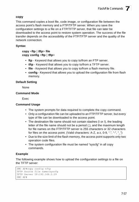
Flash/File Commands 7
copy This command copies a boot file, code image, or configuration file between the access point’s flash memory and a FTP/TFTP server. When you save the configuration settings to a file on a FTP/TFTP server, that file can later be downloaded to the access point to restore system operation. The success of the file transfer depends on the accessibility of the FTP/TFTP server and the quality of the network connection.Syntax
copy <ftp | tftp> filecopy config <ftp | tftp>
• ftp - Keyword that allows you to copy to/from an FTP server.• tftp - Keyword that allows you to copy to/from a TFTP server.• file - Keyword that allows you to copy to/from a flash memory file. • config - Keyword that allows you to upload the configuration file from flash
memory.
Default Setting
None
Command Mode
Exec
Command Usage
• The system prompts for data required to complete the copy command. • Only a configuration file can be uploaded to an FTP/TFTP server, but every
type of file can be downloaded to the access point.• The destination file name should not contain slashes (\ or /), the leading
letter of the file name should not be a period (.), and the maximum length for file names on the FTP/TFTP server is 255 characters or 32 characters for files on the access point. (Valid characters: A-Z, a-z, 0-9, “.”, “-”, “_”)
• Due to the size limit of the flash memory, the access point supports only two operation code files.
• The system configuration file must be named “syscfg” in all copy commands.
Example
The following example shows how to upload the configuration settings to a file on the TFTP server:
SMC AP#copy config tftpTFTP Source file name:syscfgTFTP Server IP:192.168.2.29SMC AP#
7-57

Command Line Interface7
The following example shows how to download a configuration file:deleteThis command deletes a file or image.
Syntax
delete <filename>
filename - Name of the configuration file or image name.
Default Setting
None
Command Mode
Exec
Caution: Beware of deleting application images from flash memory. At least one application image is required in order to boot the access point. If there are multiple image files in flash memory, and the one used to boot the access point is deleted, be sure you first use the bootfile command to update the application image file booted at startup before you reboot the access point.
Example
This example shows how to delete the test.cfg configuration file from flash memory.
Related Commands
bootfile (7-56)dir (7-59)
SMC AP#copy tftp file1. Application image2. Config file3. Boot block imageSelect the type of download<1,2,3>: [1]:2TFTP Source file name:syscfgTFTP Server IP:192.168.2.29SMC AP#
SMC AP#delete test.cfgAre you sure you wish to delete this file? <y/n>:SMC AP#
7-58

Flash/File Commands 7
dirThis command displays a list of files in flash memory.Command Mode
Exec
Command Usage
File information is shown below:
Example
The following example shows how to display all file information:
show bootfileThis command displays the name of the current operation code file that booted the system.
Syntax
show snmp filter-assignments
Command Mode
Exec
Example
Column Heading Description
File Name The name of the file.
Type (2) Operation Code and (5) Configuration file
File Size The length of the file in bytes.
SMC AP#dirFile Name Type File Size-------------------------- ---- -----------dflt-img.bin 2 1044140syscfg 5 16860syscfg_bak 5 16860zz-img.bin 2 1044140
1048576 byte(s) available
SMC AP#
SMC AP#show bootfile
Bootfile Information===================================Bootfile : ec-img.bin===================================SMC AP#
7-59

Command Line Interface7
RADIUS ClientRemote Authentication Dial-in User Service (RADIUS) is a logon authentication protocol that uses software running on a central server to control access for RADIUS-aware devices to the network. An authentication server contains a database of credentials, such as users names and passwords, for each wireless client that requires access to the access point.radius-server addressThis command specifies the primary and secondary RADIUS servers.
Syntax
radius-server [secondary] address <host_ip_address | host_name>
• secondary - Secondary server.• host_ip_address - IP address of server.• host_name - Host name of server. (Range: 1-20 characters)
Default Setting
None
Table 7-11. RADIUS Client
Command Function Mode Page
radius-server address Specifies the RADIUS server GC 7-60
radius-server port Sets the RADIUS server network port GC 7-61
radius-server key Sets the RADIUS encryption key GC 7-61
radius-server retransmit Sets the number of retries GC 7-62
radius-server timeout Sets the interval between sending authentication requests
GC 7-62
radius-server port-accounting
Sets the RADIUS Accounting server network port GC 7-63
radius-server timeout-interim
Sets the interval between transmitting accounting updates to the RADIUS server
GC 7-63
radius-server radius-mac-format
Sets the format for specifying MAC addresses on the RADIUS server
GC 7-64
radius-server vlan-format Sets the format for specifying VLAN IDs on the RADIUS server
GC 7-64
show radius Shows the current RADIUS settings Exec 7-65
7-60

RADIUS Client 7
Command ModeGlobal Configuration
Example
radius-server portThis command sets the RADIUS server network port.
Syntax
radius-server [secondary] port <port_number>
• secondary - Secondary server.• port_number - RADIUS server UDP port used for authentication messages.
(Range: 1024-65535)
Default Setting
1812
Command Mode
Global Configuration
Example
radius-server keyThis command sets the RADIUS encryption key.
Syntax
radius-server [secondary] key <key_string>
• secondary - Secondary server.• key_string - Encryption key used to authenticate logon access for client. Do
not use blank spaces in the string. (Maximum length: 20 characters)
Default Setting
DEFAULT
Command Mode
Global Configuration
Example
SMC AP(config)#radius-server address 192.168.1.25SMC AP(config)#
SMC AP(config)#radius-server port 181SMC AP(config)#
SMC AP(config)#radius-server key greenSMC AP(config)#
7-61

Command Line Interface7
radius-server retransmitThis command sets the number of retries.Syntax
radius-server [secondary] retransmit number_of_retries
• secondary - Secondary server.• number_of_retries - Number of times the access point will try to
authenticate logon access via the RADIUS server. (Range: 1 - 30)
Default Setting
3
Command Mode
Global Configuration
Example
radius-server timeoutThis command sets the interval between transmitting authentication requests to the RADIUS server.
Syntax
radius-server [secondary] timeout number_of_seconds
• secondary - Secondary server.• number_of_seconds - Number of seconds the access point waits for a reply
before resending a request. (Range: 1-60)
Default Setting
5
Command Mode
Global Configuration
Example
SMC AP(config)#radius-server retransmit 5SMC AP(config)#
SMC AP(config)#radius-server timeout 10SMC AP(config)#
7-62

RADIUS Client 7
radius-server port-accountingThis command sets the RADIUS Accounting server network port.Syntax
radius-server [secondary] port-accounting <port_number>
• secondary - Secondary server. If secondary is not specified, then the access point assumes you are configuring the primary RADIUS server.
• port_number - RADIUS Accounting server UDP port used for accounting messages. (Range: 0 or 1024-65535)
Default Setting
0 (disabled)
Command Mode
Global Configuration
Command Usage
• When the RADIUS Accounting server UDP port is specified, a RADIUS accounting session is automatically started for each user that is successfully authenticated to the access point.
Example
radius-server timeout-interimThis command sets the interval between transmitting accounting updates to the RADIUS server.
Syntax
radius-server [secondary] timeout-interim <number_of_seconds>
• secondary - Secondary server.• number_of_seconds - Number of seconds the access point waits between
transmitting accounting updates. (Range: 60-86400)
Default Setting
3600
Command Mode
Global Configuration
Command Usage
• The access point sends periodic accounting updates after every interim period until the user logs off and a “stop” message is sent.
SMC AP(config)#radius-server port-accounting 1813SMC AP(config)#
7-63

Command Line Interface7
Exampleradius-server radius-mac-formatThis command sets the format for specifying MAC addresses on the RADIUS server.
Syntax
radius-server radius-mac-format <multi-colon | multi-dash | no-delimiter | single-dash>
• multi-colon - Enter MAC addresses in the form xx:xx:xx:xx:xx:xx.• multi-dash - Enter MAC addresses in the form xx-xx-xx-xx-xx-xx.• no-delimiter - Enter MAC addresses in the form xxxxxxxxxxxx.• single-dash - Enter MAC addresses in the form xxxxxx-xxxxxx.
Default Setting
No delimiter
Command Mode
Global Configuration
Example
radius-server vlan-formatThis command sets the format for specifying VLAN IDs on the RADIUS server.
Syntax
radius-server vlan-format <hex | ascii>
• hex - Enter VLAN IDs as a hexadecimal number.• ascii - Enter VLAN IDs as an ASCII string.
Default Setting
Hex
Command Mode
Global Configuration
Example
SMC AP(config)#radius-server timeout-interim 500SMC AP(config)#
SMC AP(config)#radius-server radius-mac-format multi-dashSMC AP(config)#
SMC AP(config)#radius-server vlan-format asciiSMC AP(config)#
7-64

RADIUS Client 7
show radiusThis command displays the current settings for the RADIUS server.Default Setting
None
Command Mode
Exec
Example
SMC AP#show radius
Radius Server Information========================================IP : 0.0.0.0Port : 1812Key : *****Retransmit : 3Timeout : 5Radius MAC format : no-delimiterRadius VLAN format : HEX========================================
Radius Secondary Server Information========================================IP : 0.0.0.0Port : 1812Key : *****Retransmit : 3Timeout : 5Radius MAC format : no-delimiterRadius VLAN format : HEX========================================SMC AP#
7-65

Command Line Interface7
802.1X AuthenticationThe access point supports IEEE 802.1X access control for wireless clients. This control feature prevents unauthorized access to the network by requiring an 802.1X client application to submit user credentials for authentication. Client authentication is then verified by a RADIUS server using EAP (Extensible Authentication Protocol) before the access point grants client access to the network. The 802.1X EAP packets are also used to pass dynamic unicast session keys and static broadcast keys to wireless clients.802.1xThis command configures 802.1X as optionally supported or as required for wireless clients. Use the no form to disable 802.1X support.
Syntax
802.1x <supported | required>no 802.1x
• supported - Authenticates clients that initiate the 802.1X authentication process. Uses standard 802.11 authentication for all others.
• required - Requires 802.1X authentication for all clients.
Default Setting
Disabled
Table 7-12. 802.1X Authentication
Command Function Mode Page
802.1x Configures 802.1X as disabled, supported, or required IC-W-VAP 7-66
802.1x broadcast-key- refresh-rate
Sets the interval at which the primary broadcast keys are refreshed for stations using 802.1X dynamic keying
IC-W-VAP 7-67
802.1x session-key- refresh-rate
Sets the interval at which unicast session keys are refreshed for associated stations using dynamic keying
IC-W-VAP 7-68
802.1x session-timeout Sets the timeout after which a connected client must be re-authenticated
IC-W-VAP 7-68
802.1x-supplicant enable Enables the access point to operate as a 802.1X supplicant
GC 7-69
802.1x-supplicant user Sets the supplicant user name and password for the access point
GC 7-69
show authentication Shows all 802.1X authentication settings, as well as the address filter table
Exec 7-69
7-66

802.1X Authentication 7
Command ModeGlobal Configuration
Command Usage
• When 802.1X is disabled, the access point does not support 802.1X authentication for any station. After successful 802.11 association, each client is allowed to access the network.
• When 802.1X is supported, the access point supports 802.1X authentication only for clients initiating the 802.1X authentication process (i.e., the access point does NOT initiate 802.1X authentication). For stations initiating 802.1X, only those stations successfully authenticated are allowed to access the network. For those stations not initiating 802.1X, access to the network is allowed after successful 802.11 association.
• When 802.1X is required, the access point enforces 802.1X authentication for all 802.11 associated stations. If 802.1X authentication is not initiated by the station, the access point will initiate authentication. Only those stations successfully authenticated with 802.1X are allowed to access the network.
• 802.1X does not apply to the 10/100Base-TX port.
Example
802.1x broadcast-key-refresh-rateThis command sets the interval at which the broadcast keys are refreshed for stations using 802.1X dynamic keying.
Syntax
802.1x broadcast-key-refresh-rate <rate>
rate - The interval at which the access point rotates broadcast keys. (Range: 0 - 1440 minutes)
Default Setting
0 (Disabled)
Command Mode
Global Configuration
Command Usage
• The access point uses SMC APOL (Extensible Authentication Protocol Over LANs) packets to pass dynamic unicast session and broadcast keys to wireless clients. The 802.1x broadcast-key-refresh-rate command specifies the interval after which the broadcast keys are changed. The 802.1x session-key-refresh-rate command specifies the interval after which unicast session keys are changed.
SMC AP(config)#802.1x supportedSMC AP(config)#
7-67

Command Line Interface7
• Dynamic broadcast key rotation allows the access point to generate arandom group key and periodically update all key-management capable wireless clients.
Example
802.1x session-key-refresh-rateThis command sets the interval at which unicast session keys are refreshed for associated stations using dynamic keying.
Syntax
802.1x session-key-refresh-rate <rate>
rate - The interval at which the access point refreshes a session key. (Range: 0 - 1440 minutes)
Default Setting
0 (Disabled)
Command Mode
Global Configuration
Command Usage
Session keys are unique to each client, and are used to authenticate a client connection, and correlate traffic passing between a specific client and the access point.
Example
802.1x session-timeoutThis command sets the time period after which a connected client must be re-authenticated. Use the no form to disable 802.1X re-authentication.
Syntax
802.1x session-timeout <seconds>no 802.1x session-timeout
seconds - The number of seconds. (Range: 0-65535)
Default
0 (Disabled)
Command Mode
SMC AP(config)#802.1X broadcast-key-refresh-rate 5SMC AP(config)#
SMC AP(config)#802.1x session-key-refresh-rate 5SMC AP(config)#
7-68

802.1X Authentication 7
Global ConfigurationExample
802.1x-supplicant enableThis command enables the access point to operate as an 802.1X supplicant for authentication. Use the no form to disable 802.1X authentication of the access point.
Syntax
802.1x-supplicant enableno 802.1x-supplicant
Default
Disabled
Command Mode
Global Configuration
Command Usage
A user name and password must be configured first before the 802.1X supplicant feature can be enabled.
Example
802.1x-supplicant userThis command sets the user name and password used for authentication of the access point when operating as a 802.1X supplicant. Use the no form to clear the supplicant user name and password.
Syntax
802.1x-supplicant user <username> <password>no 802.1x-supplicant user
• username - The access point name used for authentication to the network. (Range: 1-32 alphanumeric characters)
• password - The MD5 password used for access point authentication. (Range: 1-32 alphanumeric characters)
Default
None
SMC AP(config)#802.1x session-timeout 300SMC AP(config)#
SMC AP(config)#802.1x-supplicant enableSMC AP(config)#
7-69

Command Line Interface7
Command ModeGlobal Configuration
Command Usage
The access point currently only supports EAP-MD5 CHAP for 802.1X supplicant authentication.
Example
show authenticationThis command shows all 802.1X authentication settings, as well as the address filter table.
Command Mode
Exec
Example
SMC AP(config)#802.1x-supplicant user WA6102 dot1xpassSMC AP(config)#
SMC AP#show authentication
Authentication Information===========================================================MAC Authentication Server : DISABLEDMAC Auth Session Timeout Value : 0 min802.1x supplicant : DISABLED802.1x supplicant user : EMPTY802.1x supplicant password : EMPTYAddress Filtering : ALLOWED
System Default : ALLOW addresses not found in filter table.Filter Table
MAC Address Status----------------- ----------00-70-50-cc-99-1a DENIED00-70-50-cc-99-1b ALLOWED=========================================================SMC AP(config)#
7-70

MAC Address Authentication 7
MAC Address Authentication Use these commands to define MAC authentication on the access point. For local MAC authentication, first define the default filtering policy using the address filter default command. Then enter the MAC addresses to be filtered, indicating if they are allowed or denied. For RADIUS MAC authentication, the MAC addresses and filtering policy must be configured on the RADIUS server.address filter defaultThis command sets filtering to allow or deny listed MAC addresses.
Syntax
address filter default <allowed | denied>
• allowed - Only MAC addresses entered as “denied” in the address filtering table are denied.
• denied - Only MAC addresses entered as “allowed” in the address filtering table are allowed.
Default
allowed
Command Mode
Global Configuration
Example
Table 7-13. MAC Address Authentication
Command Function Mode Page
address filter default Sets filtering to allow or deny listed addresses GC 7-71
address filter entry Enters a MAC address in the filter table GC 7-72
address filter delete Removes a MAC address from the filter table GC 7-72
mac- authentication server Sets address filtering to be performed with local or remote options
GC 7-73
mac- authentication session-timeout
Sets the interval at which associated clients will be re-authenticated with the RADIUS server authentication database
GC 7-73
show authentication Shows all 802.1X authentication settings, as well as the address filter table
Exec 7-69
SMC AP(config)#address filter default deniedSMC AP(config)#
7-71

Command Line Interface7
Related Commandsaddress filter entry (7-72)802.1x-supplicant user (7-69)
address filter entryThis command enters a MAC address in the filter table.
Syntax
address filter entry <mac-address> <allowed | denied>
• mac-address - Physical address of client. (Enter six pairs of hexadecimal digits separated by hyphens; e.g., 00-90-D1-12-AB-89.)
• allowed - Entry is allowed access.• denied - Entry is denied access.
Default
None
Command Mode
Global Configuration
Command Mode
• The access point supports up to 1024 MAC addresses.• An entry in the address table may be allowed or denied access depending
on the global setting configured for the address entry default command.
Example
Related Commands
address filter default (7-71)802.1x-supplicant user (7-69)
address filter deleteThis command deletes a MAC address from the filter table.
Syntax
address filter delete <mac-address>
mac-address - Physical address of client. (Enter six pairs of hexadecimal digits separated by hyphens.)
Default
None
SMC AP(config)#address filter entry 00-70-50-cc-99-1a allowedSMC AP(config)#
7-72

MAC Address Authentication 7
Command ModeGlobal Configuration
Example
Related Commands
802.1x-supplicant user (7-69)
mac-authentication serverThis command sets address filtering to be performed with local or remote options. Use the no form to disable MAC address authentication.
Syntax
mac-authentication server [local | remote]
• local - Authenticate the MAC address of wireless clients with the local authentication database during 802.11 association.
• remote - Authenticate the MAC address of wireless clients with the RADIUS server during 802.1X authentication.
Default
Disabled
Command Mode
Global Configuration
Example
Related Commands
address filter entry (7-72)radius-server address (7-60)802.1x-supplicant user (7-69)
mac-authentication session-timeoutThis command sets the interval at which associated clients will be re-authenticated with the RADIUS server authentication database. Use the no form to disable reauthentication.
Syntax
mac-authentication session-timeout <minutes>
minutes - Re-authentication interval. (Range: 0-1440)
SMC AP(config)#address filter delete 00-70-50-cc-99-1b SMC AP(config)#
SMC AP(config)#mac-authentication server remoteSMC AP(config)#
7-73

Command Line Interface7
Default0 (disabled)
Command Mode
Global Configuration
Example
Filtering CommandsThe commands described in this section are used to filter communications between wireless clients, control access to the management interface from wireless clients, and filter traffic using specific Ethernet protocol types.
SMC AP(config)#mac-authentication session-timeout 1SMC AP(config)#
Table 7-14. Filtering Commands
Command Function Mode Page
filter local-bridge Disables communication between wireless clients GC 7-75
filter ap-manage Prevents wireless clients from accessing the management interface
GC 7-75
filter uplink enable Ethernet port MAC address filtering GC 7-76
filter uplink Adds or deletes a MAC address from the filtering table GC 7-76
filter ethernet-type enable Checks the Ethernet type for all incoming and outgoing Ethernet packets against the protocol filtering table
GC 7-76
filter ethernet-type protocol
Sets a filter for a specific Ethernet type GC 7-77
show filters Shows the filter configuration Exec 7-78
7-74

Filtering Commands 7
filter local-bridgeThis command disables communication between wireless clients. Use the no form to disable this filtering.Syntax
filter local-bridge <all-VAP | intra-VAP>no filter local-bridge
all-VAP - When enabled, clients cannot establish wireless communications with any other client, either those associated to the same VAP interface or any other VAP interface.intra-VAP - When enabled, clients associated with a specific VAP interface cannot establish wireless communications with each other. Clients can communicate with clients associated to other VAP interfaces.
Default
Disabled
Command Mode
Global Configuration
Command Usage
This command can disable wireless-to-wireless communications between clients via the access point. However, it does not affect communications between wireless clients and the wired network.
Example
filter ap-manageThis command prevents wireless clients from accessing the management interface on the access point. Use the no form to disable this filtering.
Syntax
filter ap-manageno filter ap-manage
Default
Enabled
Command Mode
Global Configuration
Example
SMC AP(config)#filter local-bridgeSMC AP(config)#
SMC AP(config)#filter AP-manageSMC AP(config)#
7-75

Command Line Interface7
filter uplink enableThis command enables filtering of MAC addresses from the Ethernet port.Syntax
[no] filter uplink enable
Default
Disabled
Command Mode
Global Configuration
Example
filter uplinkThis command adds or deletes MAC addresses from the uplink filtering table.
Syntax
filter uplink <add | delete> MAC address
MAC address - Specifies a MAC address in the form xx-xx-xx-xx-xx-xx. A maximum of four addresses can be added to the filtering table.
Default
Disabled
Command Mode
Global Configuration
Example
filter ethernet-type enableThis command checks the Ethernet type on all incoming and outgoing Ethernet packets against the protocol filtering table. Use the no form to disable this feature.
Syntax
filter ethernet-type enableno filter ethernet-type enable
Default
Disabled
Command Mode
SMC AP(config)#filter uplink enableSMC AP(config)#
SMC AP(config)#filter uplink add 00-12-34-56-78-9aSMC AP(config)#
7-76

Filtering Commands 7
Global ConfigurationCommand Usage
This command is used in conjunction with the filter ethernet-type protocol command to determine which Ethernet protocol types are to be filtered.
Example
Related Commands
filter ethernet-type protocol (7-77)
filter ethernet-type protocolThis command sets a filter for a specific Ethernet type. Use the no form to disable filtering for a specific Ethernet type.
Syntax
filter ethernet-type protocol <protocol>no filter ethernet-type protocol <protocol>
protocol - An Ethernet protocol type. (Options: ARP, RARP, Berkeley-Trailer-Negotiation, LAN-Test, X25-Level-3, Banyan, CDP, DEC XNS, DEC-MOP-Dump-Load, DEC-MOP, DEC-LAT, Ethertalk, Appletalk-ARP, Novell-IPX(old), Novell-IPX(new), EAPOL, Telxon-TXP, Aironet-DDP, Enet-Config-Test, IP, IPv6, NetBEUI, PPPoE_Discovery, PPPoE_PPP_Session)
Default
None
Command Mode
Global Configuration
Command Usage
Use the filter ethernet-type enable command to enable filtering for Ethernet types specified in the filtering table, or the no filter ethernet-type enable command to disable all filtering based on the filtering table.
Example
Related Commands
filter ethernet-type enable (7-76)
SMC AP(config)#filter ethernet-type enableSMC AP(config)#
SMC AP(config)#filter ethernet-type protocol ARPSMC AP(config)#
7-77

Command Line Interface7
show filtersThis command shows the filter options and protocol entries in the filter table.Command Mode
Exec
Example
WDS Bridge Commands The commands described in this section are used to set the operation mode for each access point interface and configure WIreless Distribution System (WDS) forwarding table settings.
SMC AP#show filters
Protocol Filter Information=======================================================================Local Bridge :Traffic among all client STAs blockedAP Management :ENABLEDEthernet Type Filter :DISABLED
UPlink Access Table-----------------------------------------------------------------------UPlink access control:EnabledUPlink MAC access control list :00-12-34-56-78-9a-----------------------------------------------------------------------Enabled Protocol Filters-----------------------------------------------------------------------No protocol filters are enabled=======================================================================SMC AP#
Command Function Mode Pagebridge mode Selects Master or Slave mode. IC-W 7-79bridge role Selects the bridge operation mode for a radio interface IC-W 7-79bridge channel-auto-sync Automatically finds the parent bridge operating
channelIC-W 7-80
bridge-link parent Configures the MAC addresses of the parent bridge node
IC-W 7-80
bridge-link child Configures MAC addresses of connected child bridge nodes
IC-W 7-81
bridge dynamic-entry age-time
Sets the aging time for dynamic entries in the WDS forwarding table
GC 7-82
show bridge aging-time Displays the current WDS forwarding table aging time Exec 7-82show bridge filter-entry Displays current entries in the bridge MAC address
tableExec 7-83
show bridge link Displays current bridge settings for specified interfaces Exec 7-83
7-78

WDS Bridge Commands 7
bridge modeThis command selects between Master and Slave mode.Syntax
bridge mode <master | slave>
• master - Operates as a master enabling up to five slave links.• slave - Operates as a slave with only one link to the master.
Default Setting
SMC2890W-AG: SlaveSMC2891W-AG: Master
Command Mode
Interface Configuration (Wireless)
Example
bridge role (WDS)This command selects the bridge operation mode for the radio interface.
Syntax
bridge role <ap | repeater | bridge | root-bridge>
• ap - Operates only as an access point for wireless clients.• repeater - Operates as a wireless repeater, extending the range for remote
wireless clients and connecting them to the root bridge. The “Parent” link to the root bridge must be configured. In this mode, traffic is not forwarded to the Ethernet port from the radio interface.
• bridge - Operates as a bridge to other access points also in bridge mode.• root-bridge - Operates as the root bridge in the wireless bridge network.
Default Setting
AP
Command Mode
Interface Configuration (Wireless)
Command Usage
• When the bridge role is set to “repeater,” the “Parent” link to the root bridge must be configured (see “bridge-link parent” on page 77-80). When the access point is operating in this mode, traffic is not forwarded to the Ethernet port from the radio interface.
• Up to four WDS bridge links (MAC addresses) per radio interface can be specified for each unit in the wireless bridge network. One unit only must be
SMC AP(if-wireless a)#bridge mode masterSMC AP(if-wireless a)#
7-79

Command Line Interface7
configured as the “root bridge” in the wireless network. The root bridge is the unit connected to the main core of the wired LAN. Other bridges need to specify one “Parent” link to the root bridge or to a bridge connected to the root bridge. The other seven WDS links are available as “Child” links to other bridges.• The bridge link on the radio interface always uses the default VAP interface. In any bridge mode, VAP interfaces 1 to 7 are not available for use.
Example
bridge channel-auto-syncThis command allows a child bridge to automatically find the operating channel of its parent bridge.
Caution: Do not enable Channel Auto Sync on a master bridge if there is no root bridge acting as the master bridge's parent.
Syntax
bridge channel-auto-sync <enable | disable>
• enable - The bridge will automatically search and find the operating channel of its parent.• disable - The bridge must have the operating channel manually set to the
operating channel of its parent bridge.
Default Setting
Disabled
Command Mode
Interface Configuration (Wireless)
Example
bridge-link parentThis command configures the MAC address of the parent bridge node.
Syntax
bridge-link parent <mac-address>
mac-address - The wireless MAC address of the parent bridge unit. (12 hexadecimal digits in the form “xx-xx-xx-xx-xx-xx”).
SMC AP(if-wireless a)#bridge role root-bridgeSMC AP(if-wireless a)#
SMC AP(if-wireless a)#bridge channel-auto-sync enableEnable channel auto sync!!SMC AP(if-wireless a)#
7-80

WDS Bridge Commands 7
Default SettingNone
Command Mode
Interface Configuration (Wireless)
Command Usage
Every bridge (except the root bridge) in the wireless bridge network must specify the MAC address of the parent bridge that is linked to the root bridge, or the root bridge itself.
Example
bridge-link childThis command configures the MAC addresses of child bridge nodes.
Syntax
bridge-link child <index> <mac-address>
- index - The link index number of the child node. (Range: 1 - 6)- mac-address - The wireless MAC address of a child bridge unit.
(12 hexadecimal digits in the form “xx-xx-xx-xx-xx-xx”).
Default Setting
None
Command Mode
Interface Configuration (Wireless)
Command Usage
• In root bridge mode, up to six child bridge links can be specified using link index numbers 1 to 6.
• In bridge mode, up to five child links can be specified using link index numbers 2 to 6. Index number 1 is reserved for the parent link, which must be set using the bridge parent command.
Example
SMC AP(if-wireless a)#bridge-link parent 00-08-2d-69-3a-51SMC AP(if-wireless a)#
SMC AP(if-wireless a)#bridge-link child 2 00-08-3e-84-bc-6dSMC AP(if-wireless a)#bridge-link child 3 00-08-3e-85-13-f2SMC AP(if-wireless a)#bridge-link child 4 00-08-3e-84-79-31SMC AP(if-wireless a)#
7-81

Command Line Interface7
bridge dynamic-entry age-timeThis command sets the time for aging out dynamic entries in the WDS forwarding table.Syntax
bridge dynamic-entry age-time <seconds>
seconds - The time to age out an address entry. (Range: 10-10000 seconds).
Default Setting
300 seconds
Command Mode
Global Configuration
Command Usage
If the MAC address of an entry in the address table is not seen on the associated interface for longer than the aging time, the entry is discarded.
Example
show bridge aging-timeThis command displays the current WDS forwarding table aging time setting.
Command Mode
Exec
Example
SMC AP(config)#bridge dynamic-entry age-time 100SMC AP(config)#
SMC AP#show bridge aging-timeAging time: 300SMC AP#
7-82

WDS Bridge Commands 7
show bridge filter-entryThis command displays current entries in the WDS forwarding table.Command Mode
Exec
Example
show bridge linkThis command displays WDS bridge link and spanning tree settings for specified interfaces.
Syntax
show bridge link <ethernet | wireless <a | g> [index]>
• ethernet - Specifies the Ethernet interface.• wireless - Specifies a wireless interface.
- a - The 802.11a radio interface.- g - The 802.11g radio interface.- index - The index number of a bridge link. (Range: 1 - 6)
Command Mode
Exec
SMC AP#show bridge filter-entry
max entry numbers =512current entry nums =13**************************************************************************************************** Bridge MAC Addr Table ************************************************************************************************************| MAC | Port |Fwd_type| VlanID|origin life|remain Life| Type | 01 80 c2 00 00 00 0 5 4095 300 300 Static 01 80 c2 00 00 03 0 5 4095 300 300 Static 00 30 f1 f0 9b 20 1 0 1 300 300 Static 00 30 f1 f0 9b 21 1 0 1 300 300 Static 00 30 f1 f0 9b 22 1 0 1 300 300 Static 00 30 f1 f0 9b 23 1 0 1 300 300 Static 00 30 f1 f0 9b 24 1 0 1 300 300 Static 00 30 f1 f0 9b 25 1 0 1 300 300 Static 00 30 f1 f0 9b 26 1 0 1 300 300 Static 00 30 f1 f0 9b 27 1 0 1 300 300 Static 00 30 f1 2f be 30 1 3 0 300 175 Dynamic 00 30 f1 f0 9a 9c 1 0 1 300 300 Static ff ff ff ff ff ff 0 4 4095 300 300 StaticSMC AP#
7-83

Command Line Interface7
ExampleSMC AP#show bridge link wireless a
Interface Wireless A WDS Information====================================AP Role: BridgeChannel Auto Sync: DisableParent: 00-12-34-56-78-9aChild: Child 2: 00-08-12-34-56-de Child 3: 00-00-00-00-00-00 Child 4: 00-00-00-00-00-00 Child 5: 00-00-00-00-00-00 Child 6: 00-00-00-00-00-00STAs: No WDS Stations.SMC AP#
SMC AP#show bridge link wireless a 2
Port-No : 11status : Enabledstate : Disabledpriority : 0path cost : 19message age Timer : Inactivemessage age : 4469designated-root : priority = 32768, MAC = 00:30:F1:F0:9A:9Cdesignated-cost : 0designated-bridge : priority = 32768, MAC = 00:30:F1:F0:9A:9Cdesignated-port : priority = 0, port No = 11forward-transitions : 0SMC AP#
SMC AP#show bridge link ethernet
status : Enabledstate : Forwardingpriority : 0path cost : 19message age Timer : Inactivemessage age : 4346designated-root : priority = 32768, MAC = 00:30:F1:F0:9A:9Cdesignated-cost : 0designated-bridge : priority = 32768, MAC = 00:30:F1:F0:9A:9Cdesignated-port : priority = 0, port No = 1forward-transitions : 1SMC AP#
7-84

Spanning Tree Commands 7
Spanning Tree CommandsThe commands described in this section are used to set the MAC address table aging time and spanning tree parameters for both the Ethernet and wireless interfaces.bridge stp enableThis command enables the Spanning Tree Protocol. Use the no form to disable the Spanning Tree Protocol.
Syntax bridge stp enableno bridge stp enable
Default Setting Enabled
Command Mode Global Configuration
Example This example globally enables the Spanning Tree Protocol.
Table 7-15. Bridge CommandsCommand Function Mode Pagebridge stp enable Enables the Spanning Tree feature GC 7-85bridge stp forwarding-delay Configures the spanning tree bridge forward time GC 7-86bridge stp hello-time Configures the spanning tree bridge hello time GC 7-86bridge stp max-age Configures the spanning tree bridge maximum age GC 7-87bridge stp priority Configures the spanning tree bridge priority GC 7-87bridge-link path-cost Configures the spanning tree path cost of a port IC 7-88bridge-link port-priority Configures the spanning tree priority of a port IC 7-88show bridge stp Displays the global spanning tree settings Exec 7-89show bridge link Displays current bridge settings for specified interfaces Exec 7-83
SMC AP(config)bridge stp enableSMC AP(config)
7-85

Command Line Interface7
bridge stp forwarding-delayUse this command to configure the spanning tree bridge forward time globally for the wireless bridge. Use the no form to restore the default.Syntax bridge stp forwarding-delay <seconds>no bridge stp forwarding-delay
seconds - Time in seconds. (Range: 4 - 30 seconds)The minimum value is the higher of 4 or [(max-age / 2) + 1].
Default Setting 15 seconds
Command Mode Global Configuration
Command Usage This command sets the maximum time (in seconds) the root device will wait before changing states (i.e., discarding to learning to forwarding). This delay is required because every device must receive information about topology changes before it starts to forward frames. In addition, each port needs time to listen for conflicting information that would make it return to the discarding state; otherwise, temporary data loops might result.
Example
bridge stp hello-timeUse this command to configure the spanning tree bridge hello time globally for the wireless bridge. Use the no form to restore the default.
Syntax bridge stp hello-time <time>no bridge stp hello-time
time - Time in seconds. (Range: 1-10 seconds). The maximum value is the lower of 10 or [(max-age / 2) -1].
Default Setting 2 seconds
Command Mode Global Configuration
Command Usage This command sets the time interval (in seconds) at which the root device transmits a configuration message.
SMC AP(config)#bridge stp forwarding-delay 20SMC AP(config)#
7-86

Spanning Tree Commands 7
Examplebridge stp max-ageUse this command to configure the spanning tree bridge maximum age globally for the wireless bridge. Use the no form to restore the default.
Syntax bridge stp max-age <seconds>no bridge stp max-age
seconds - Time in seconds. (Range: 6-40 seconds)The minimum value is the higher of 6 or [2 x (hello-time + 1)].The maximum value is the lower of 40 or [2 x (forward-time - 1)].
Default Setting 20 seconds
Command Mode Global Configuration
Command Usage This command sets the maximum time (in seconds) a device can wait without receiving a configuration message before attempting to reconfigure. All device ports (except for designated ports) should receive configuration messages at regular intervals. Any port that ages out STP information (provided in the last configuration message) becomes the designated port for the attached LAN. If it is a root port, a new root port is selected from among the device ports attached to the network.
Example
bridge stp priorityUse this command to configure the spanning tree priority globally for the wireless bridge. Use the no form to restore the default.
Syntax bridge stp priority<priority>no bridge stp priority
priority - Priority of the bridge. (Range: 0 - 65535)
Default Setting 32768
SMC AP(config)#bridge stp hello-time 5SMC AP(config)#
SMC AP(config)#bridge stp max-age 40SMC AP(config)#
7-87

Command Line Interface7
Command ModeGlobal Configuration
Command Usage Bridge priority is used in selecting the root device, root port, and designated port. The device with the highest priority becomes the STP root device. However, if all devices have the same priority, the device with the lowest MAC address will then become the root device.
Example
bridge-link path-costUse this command to configure the spanning tree path cost for the specified port.
Syntax bridge-link path-cost <index> <cost>
• index - Specifies the bridge link number on the wireless bridge. (Range: 1-6 required on wireless interface only)
• cost - The path cost for the port. (Range: 1-65535)
Default Setting 19
Command Mode Interface Configuration
Command Usage • This command is used by the Spanning Tree Protocol to determine the best
path between devices. Therefore, lower values should be assigned to ports attached to faster media, and higher values assigned to ports with slower media.
• Path cost takes precedence over port priority.
Example
bridge-link port-priorityUse this command to configure the priority for the specified port.
Syntax bridge-link port-priority <index> <priority>
• index - Specifies the bridge link number on the wireless bridge. (Range: 1-6 required on wireless interface only)
• priority - The priority for a port. (Range: 1-255)
SMC AP(config)#bridge stp-bridge priority 40000SMC AP(config)#
SMC AP(if-wireless a)#bridge-link path-cost 1 50SMC AP(if-wireless a)#
7-88

Spanning Tree Commands 7
Default Setting128
Command Mode Interface Configuration
Command Usage • This command defines the priority for the use of a port in the Spanning Tree
Protocol. If the path cost for all ports on a wireless bridge are the same, the port with the highest priority (that is, lowest value) will be configured as an active link in the spanning tree.
• Where more than one port is assigned the highest priority, the port with lowest numeric identifier will be enabled.
Example
Related Commandsbridge-link path-cost (7-88)
show bridge stpThis command displays aging time and spanning tree settings for the Ethernet and wireless interfaces.
Syntaxshow bridge stp
Command ModeExec
Example
SMC AP(if-wireless a)#bridge-link port-priority 1 64SMC AP(if-wireless a)#
SMC AP#show bridge stp
Bridge MAC : 00:12:CF:05:B7:84Status : Disabledpriority : 0designated-root : priority = 0, MAC = 00:00:00:00:00:00root-path-cost : 0root-Port-no : 0Hold Time : 1 SecondsHello Time : 2 SecondsMaximum Age : 20 SecondsForward Delay : 15 Secondsbridge Hello Time : 2 Secondsbridge Maximum Age : 20 Secondsbridge Forward Delay : 15 Secondstime-since-top-change: 89185 Secondstopology-change-count: 0SMC AP#
7-89

Command Line Interface7
Ethernet Interface Commands The commands described in this section configure connection parameters for the Ethernet port and wireless interface.interface ethernetThis command enters Ethernet interface configuration mode.
Default Setting
None
Command Mode
Global Configuration
Example
To specify the 10/100Base-TX network interface, enter the following command:
Table 7-16. Ethernet Interface Commands
Command Function Mode Page
interface ethernet Enters Ethernet interface configuration mode GC 7-90
dns primary- server Specifies the primary name server IC-E 7-91
dns secondary- server Specifies the secondary name server IC-E 7-91
ip address Sets the IP address for the Ethernet interface IC-E 7-91
ip dhcp Submits a DHCP request for an IP address IC-E 7-92
speed-duplex Configures speed and duplex operation on the Ethernet interface
IC-E 7-93
shutdown Disables the Ethernet interface IC-E 7-94
show interface ethernet Shows the status for the Ethernet interface Exec 7-94
SMC AP(config)#interface ethernet SMC AP(if-ethernet)#
7-90

Ethernet Interface Commands 7
dns serverThis command specifies the address for the primary or secondary domain name server to be used for name-to-address resolution.Syntax
dns primary-server <server-address>dns secondary-server <server-address>
• primary-server - Primary server used for name resolution.• secondary-server - Secondary server used for name resolution.• server-address - IP address of domain-name server.
Default Setting
None
Command Mode
Global Configuration
Command Usage
The primary and secondary name servers are queried in sequence.
Example
This example specifies two domain-name servers.
Related Commands
show interface ethernet (7-94)
ip address This command sets the IP address for the access point. Use the no form to restore the default IP address.
Syntax
ip address <ip-address> <netmask> <gateway>no ip address
• ip-address - IP address • netmask - Network mask for the associated IP subnet. This mask identifies
the host address bits used for routing to specific subnets. • gateway - IP address of the default gateway
Default Setting
IP address: 192.168.2.2Netmask: 255.255.255.0
SMC AP(if-ethernet)#dns primary-server 192.168.1.55SMC AP(if-ethernet)#dns secondary-server 10.1.0.55SMC AP(if-ethernet)#
7-91

Command Line Interface7
Command ModeInterface Configuration (Ethernet)
Command Usage
• DHCP is enabled by default. To manually configure a new IP address, you must first disable the DHCP client with the no ip dhcp command.
• You must assign an IP address to this device to gain management access over the network or to connect the access point to existing IP subnets. You can manually configure a specific IP address using this command, or direct the device to obtain an address from a DHCP server using the ip dhcp command. Valid IP addresses consist of four numbers, 0 to 255, separated by periods. Anything outside this format will not be accepted by the configuration program.
Example
Related Commands
ip dhcp (7-92)
ip dhcp This command enables the access point to obtain an IP address from a DHCP server. Use the no form to restore the default IP address.
Syntax
ip dhcpno ip dhcp
Default Setting
Enabled
Command Mode
Interface Configuration (Ethernet)
Command Usage
• You must assign an IP address to this device to gain management access over the network or to connect the access point to existing IP subnets. You can manually configure a specific IP address using the ip address command, or direct the device to obtain an address from a DHCP server using this command.
SMC AP(config)#interface ethernetEnter Ethernet configuration commands, one per line.SMC AP(if-ethernet)#ip address 192.168.1.2 255.255.255.0 192.168.1.253SMC AP(if-ethernet)#
7-92

Ethernet Interface Commands 7
• When you use this command, the access point will begin broadcastingDHCP client requests. The current IP address (i.e., default or manually configured address) will continue to be effective until a DHCP reply is received. Requests will be broadcast periodically by this device in an effort to learn its IP address. (DHCP values can include the IP address, subnet mask, and default gateway.)
Example
Related Commands
ip address (7-91)
speed-duplexThis command configures the speed and duplex mode of a given interface when autonegotiation is disabled. Use the no form to restore the default.
Syntax
speed-duplex <auto | 10MH | 10MF | 100MF | 100MH>
• auto - autonegotiate speed and duplex mode• 10MH - Forces 10 Mbps, half-duplex operation• 10MF - Forces 10 Mbps, full-duplex operation • 100MH - Forces 100 Mbps, half-duplex operation • 100MF - Forces 100 Mbps, full-duplex operation
Default Setting
Auto-negotiation is enabled by default.
Command Mode
Interface Configuration (Ethernet)
Command Usage
If autonegotiation is disabled, the speed and duplex mode must be configured to match the setting of the attached device.
Example
The following example configures the Ethernet port to 100 Mbps, full-duplex operation.
SMC AP(config)#interface ethernetEnter Ethernet configuration commands, one per line.SMC AP(if-ethernet)#ip dhcpSMC AP(if-ethernet)#
SMC AP(if-ethernet)#speed-duplex 100mfSMC AP(if-ethernet)#
7-93

Command Line Interface7
shutdown This command disables the Ethernet interface. To restart a disabled interface, use the no form.Syntax
shutdownno shutdown
Default Setting
Interface enabled
Command Mode
Interface Configuration (Ethernet)
Command Usage
This command allows you to disable the Ethernet port due to abnormal behavior (e.g., excessive collisions), and reenable it after the problem has been resolved. You may also want to disable the Ethernet port for security reasons.
Example
The following example disables the Ethernet port.
show interface ethernetThis command displays the status for the Ethernet interface.
Syntax
show interface [ethernet]
Default Setting
Ethernet interface
Command Mode
Exec
SMC AP(if-ethernet)#shutdownSMC AP(if-ethernet)#
7-94

Wireless Interface Commands 7
ExampleWireless Interface CommandsThe commands described in this section configure connection parameters for the wireless interfaces.
SMC AP#show interface ethernetEthernet Interface Information========================================IP Address : 192.168.2.2Subnet Mask : 255.255.255.0Default Gateway : 192.168.1.253Primary DNS : 192.168.1.55Secondary DNS : 10.1.0.55Speed-duplex : 100Base-TX Half DuplexAdmin status : UpOperational status : Up========================================SMC AP#
Table 7-17. Wireless Interface Commands
Command Function Mode Page
interface wireless Enters wireless interface configuration mode GC 7-97
vap Provides access to the VAP interface configuration mode
IC-W 7-97
speed Configures the maximum data rate at which the access point transmits unicast packets
IC-W 7-98
turbo Configures turbo mode to use a faster data rate IC-W (a) 7-98
multicast-data-rate Configures the maximum rate for transmitting multicast packets on the wireless interface
IC-W 7-99
channel Configures the radio channel IC-W 7-100
transmit-power Adjusts the power of the radio signals transmitted from the access point
IC-W 7-100
radio-mode Forces the operating mode of the 802.11g radio IC-W (b/g) 7-101
preamble Sets the length of the 802.11g signal preamble IC-W (b/g) 7-102
antenna control Selects the antenna control method to use for the radio
IC-W 7-103
antenna id Selects the antenna ID to use for the radio IC-W 7-103
antenna location Selects the location of the antenna IC-W 7-104
7-95

Command Line Interface7
beacon-interval Configures the rate at which beacon signals are transmitted from the access point
IC-W 7-105
dtim-period Configures the rate at which stations in sleep mode must wake up to receive broadcast/multicast transmissions
IC-W 7-105
fragmentation- length Configures the minimum packet size that can be fragmented
IC-W 7-106
rts-threshold Sets the packet size threshold at which an RTS must be sent to the receiving station prior to the sending station starting communications
IC-W 7-107
super-a Enables Atheros proprietary Super A performance enhancements
IC-W (a) 7-108
super-g Enables Atheros proprietary Super G performance enhancements
IC-W (b/g) 7-108
description Adds a description to the wireless interface IC-W-VAP 7-109
ssid Configures the service set identifier IC-W-VAP 7-109
closed system Opens access to clients without a pre-configured SSID
IC-W-VAP 7-110
max-association Configures the maximum number of clients that can be associated with the access point at the same time
IC-W-VAP 7-110
assoc- timeout-interval Configures the idle time interval (when no frames are sent) after which a client is disassociated from the VAP interface
IC-W-VAP 7-111
auth- timeout-value Configures the time interval after which clients must be re-authenticated
IC-W-VAP 7-111
shutdown Disables the wireless interface IC-W-VAP 7-111
show interface wireless Shows the status for the wireless interface Exec 7-113
show station Shows the wireless clients associated with the access point
Exec 7-115
Table 7-17. Wireless Interface Commands
Command Function Mode Page
7-96

Wireless Interface Commands 7
interface wirelessThis command enters wireless interface configuration mode.Syntax
interface wireless <a | g>
• a - 802.11a radio interface.• g - 802.11g radio interface.
Default Setting
None
Command Mode
Global Configuration
Example
To specify the 802.11a interface, enter the following command:
vapThis command provides access to the VAP (Virtual Access Point) interface configuration mode.
Syntax
vap <vap-id>
vap-id - The number that identifies the VAP interface. (Options: 0-3)
Default Setting
None
Command Mode
Interface Configuration (Wireless)
Example
SMC AP(config)#interface wireless aSMC AP(if-wireless a)#
SMC AP(if-wireless g)#vap 0SMC AP(if-wireless g: VAP[0])#
7-97

Command Line Interface7
speedThis command configures the maximum data rate at which the access point transmits unicast packets.Syntax
speed <speed>
speed - Maximum access speed allowed for wireless clients. (Options for 802.11a: 6, 9, 12, 18, 24, 36, 48, 54 Mbps) (Options for 802.11b/g: 1, 2, 5.5, 6, 9, 11, 12, 18, 24, 36, 48, 54 Mbps)
Default Setting
54 Mbps
Command Mode
Interface Configuration (Wireless)
Command Usage
• The maximum transmission distance is affected by the data rate. The lower the data rate, the longer the transmission distance. Please refer to the table for maximum distances on page C-5.
• When turbo mode is enabled (page 7-109) for 802.11a, the effective maximum speed specified by this command is double the entered value (e.g., setting the speed to 54 Mbps limits the effective maximum speed to 108 Mbps).
Example
turboThis command sets the access point to an enhanced proprietary modulation mode (not regulated in IEEE 802.11a) that provides a higher data rate of up to 108 Mbps.
Syntax
turbo <static | dynamic>no turbo
static - Always uses turbo mode.dynamic - Will use turbo mode when no other nearby access points are detected or active.
Default Setting
Disabled
Command Mode
Interface Configuration (Wireless - 802.11a)
SMC AP(if-wireless g)#speed 6SMC AP(if-wireless g)#
7-98

Wireless Interface Commands 7
Command Usage• The normal 802.11a wireless operation mode provides connections up to 54 Mbps. Turbo Mode is an enhanced mode (not regulated in IEEE 802.11a) that provides a higher data rate of up to 108 Mbps. Enabling Turbo Mode allows the access point to provide connections up to 108 Mbps.
• In normal mode, the access point provides a channel bandwidth of 20 MHz, and supports the maximum number of channels permitted by local regulations (e.g., 11 channels for the United States). In Turbo Mode, the channel bandwidth is increased to 40 MHz to support the increased data rate. However, this reduces the number of channels supported (e.g., 5 channels for the United States).
Example
multicast-data-rateThis command configures the maximum data rate at which the access point transmits multicast and management packets (excluding beacon packets) on the wireless interface.
Syntax
multicast-data-rate <speed>
speed - Maximum transmit speed allowed for multicast data. (Options for 802.11a: 6, 12, 24 Mbps)(Options for 802.11b/g; 1, 2, 5.5, 11 Mbps)
Default Setting
1 Mbps for 802.11b/g6 Mbps for 802.11a
Command Mode
Interface Configuration (Wireless)
Example
SMC AP(if-wireless a)#turboSMC AP(if-wireless a)#
SMC AP(if-wireless g)#multicast-data-rate 5.5SMC AP(if-wireless g)#
7-99

Command Line Interface7
channelThis command configures the radio channel through which the access point communicates with wireless clients.Syntax
channel <channel | auto>
• channel - Manually sets the radio channel used for communications with wireless clients. (Range for 802.11a: 36, 40, 44, 48, 52, 56, 60, 64, 149, 153, 157, 161, 165 for normal mode, and 42, 50, 58, 152, 160 for turbo mode; Range for 802.11b/g: 1 to 14)
• auto - Automatically selects an unoccupied channel (if available). Otherwise, the lowest channel is selected.
Default Setting
Automatic channel selection
Command Mode
Interface Configuration (Wireless)
Command Usage
• The available channel settings are limited by local regulations, which determine the number of channels that are available.
• When multiple access points are deployed in the same area, be sure to choose a channel separated by at least two channels for 802.11a to avoid having the channels interfere with each other, and at least five channels for 802.11b/g. You can deploy up to four access points in the same area for 802.11a (e.g., channels 36, 56, 149, 165) and three access points for 802.11b/g (e.g., channels 1, 6, 11).
• For most wireless adapters, the channel for wireless clients is automatically set to the same as that used by the access point to which it is linked.
Example
transmit-powerThis command adjusts the power of the radio signals transmitted from the access point.
Syntax
transmit-power <signal-strength>
signal-strength - Signal strength transmitted from the access point. (Options: full, half, quarter, eighth, min)
SMC AP(if-wireless g)#channel 1SMC AP(if-wireless g)#
7-100

Wireless Interface Commands 7
Default Settingfull
Command Mode
Interface Configuration (Wireless)
Command Usage
• The “min” keyword indicates minimum power.• The longer the transmission distance, the higher the transmission power
required. But to support the maximum number of users in an area, you must keep the power as low as possible. Power selection is not just a trade off between coverage area and maximum supported clients. You also have to ensure that high strength signals do not interfere with the operation of other radio devices in your area.
Example
radio-modeThis command forces the operating mode for the 802.11g wireless interface.
Syntax
radio-mode <b | g | b+g>
• b - b-only mode: Both 802.11b and 802.11g clients can communicate with the access point, but 802.11g clients can only transfer data at 802.11b standard rates (up to 11 Mbps).
• g - g-only mode: Only 802.11g clients can communicate with the access point (up to 54 Mbps).
• b+g - b & g mixed mode: Both 802.11b and 802.11g clients can communicate with the access point (up to 54 Mbps).
Default Setting
b+g mode
Command Mode
Interface Configuration (Wireless - 802.11g)
Command Usage
• For Japan, only 13 channels are available when set to g or b+g modes. When set to b mode, 14 channels are available.
• Both the 802.11g and 802.11b standards operate within the 2.4 GHz band. If you are operating in g mode, any 802.11b devices in the service area will contribute to the radio frequency noise and affect network performance.
SMC AP(if-wireless g)#transmit-power halfSMC AP(if-wireless g)#
7-101

Command Line Interface7
ExamplepreambleThis command sets the length of the signal preamble that is used at the start of a 802.11b/g data transmission.
Syntax
preamble [long | short-or-long]
• long - Sets the preamble to long (192 microseconds).• short-or-long - Sets the preamble to short if no 802.11b clients are
detected (96 microseconds).
Default Setting
Short-or-Long
Command Mode
Interface Configuration (Wireless - 802.11b/g)
Command Usage
• Using a short preamble instead of a long preamble can increase data throughput on the access point, but requires that all clients can support a short preamble.
• Set the preamble to long to ensure the access point can support all 802.11b and 802.11g clients.
Example
SMC AP(if-wireless g)#radio-mode gSMC AP(if-wireless g)#
SMC AP(if-wireless g)#preamble shortSMC AP(if-wireless g)#
7-102

Wireless Interface Commands 7
antenna controlThis command selects the use of two diversity antennas or a single antenna for the radio interface.Syntax
antenna control <diversity | left | right>
• diversity - The radio uses two identical antennas in a diversity mode.• left - The radio uses a single antenna on the left side. Select this method
when using an optional external antenna that is connected to the left antenna connector. Also select this method when using the integrated 5 GHz antenna.
• right - The radio uses a single antenna on the right side. Select this method when using an optional external antenna that is connected to the right antenna connector.
Default Setting
Diversity
Command Mode
Interface Configuration (Wireless)
Command Usage
The antenna ID must be selected in conjunction with the antenna control method to configure proper use of any of the antenna options.
Example
antenna idThis command specifies the antenna type connected to the access point represented by a four-digit hexadecimal ID number, either the integrated antenna (ID:0000) or an optional external antenna.
Syntax
antenna id <antenna-id>
• antenna-id - Specifies the ID number of an approved antenna that is connected to the access point(Range: 0x0000 - 0xFFFF)
Default Setting
0x0000 (Integrated antenna)
SMC AP(if-wireless g)#antenna control rightSMC AP(if-wireless g)#
7-103

Command Line Interface7
Command ModeInterface Configuration (Wireless)
Command Usage
• See “External Antenna Options” on page 1-5 for a list of the available antenna options and their part numbers.
• The optional external antennas (if any) that are certified for use with the access point are listed by typing antenna control id ?. Selecting the correct antenna ID ensures that the access point's radio transmissions are within regulatory power limits for the country of operation.
• The antenna ID must be selected in conjunction with the antenna control method to configure proper use of any of the antenna options.
• If there is no integrated antenna on the unit for the wireless interface, the default setting is indicated as "id=0x0000, module=NA."
Example
antenna locationThis command selects the antenna mounting location for the radio interface.
Syntax
antenna location <indoor | outdoor>
• indoor - The antenna is mounted indoors.• outdoor - The antenna is mounted outdoors.
Default Setting
Indoor
Command Mode
Interface Configuration (Wireless)
Command Usage
• Selecting the correct location ensures that the access point only uses radio channels that are permitted in the country of operation.
Example
SMC AP(if-wireless g)#antenna id ? id=0x0000, module=NA id=0x0106, module=ACC04-050090 Directional Panel Ant. id=0x0107, module=ACC04-05028A Omni-Directional Ant. id=0x0108, module=ACC04-05427A Omni-Directional Ant. id=0x0109, module=ACC04-053830 0 Degree Sector Ant.SMC AP(if-wireless g)#antenna id 0000SMC AP(if-wireless g)#
SMC AP(if-wireless g)#antenna location indoorSMC AP(if-wireless g)#
7-104

Wireless Interface Commands 7
beacon-interval This command configures the rate at which beacon signals are transmitted from the access point.Syntax
beacon-interval <interval>
interval - The rate for transmitting beacon signals. (Range: 20-1000 milliseconds)
Default Setting
100
Command Mode
Interface Configuration (Wireless)
Command Usage
The beacon signals allow wireless clients to maintain contact with the access point. They may also carry power-management information.
Example
dtim-period This command configures the rate at which stations in sleep mode must wake up to receive broadcast/multicast transmissions.
Syntax
dtim-period <interval>
interval - Interval between the beacon frames that transmit broadcast or multicast traffic. (Range: 1-255 beacon frames)
Default Setting
1
Command Mode
Interface Configuration (Wireless)
Command Usage
• The Delivery Traffic Indication Map (DTIM) packet interval value indicates how often the MAC layer forwards broadcast/multicast traffic. This parameter is necessary to wake up stations that are using Power Save mode.
• The DTIM is the interval between two synchronous frames with broadcast/multicast information. The default value of 2 indicates that the access point
SMC AP(if-wireless g)#beacon-interval 150SMC AP(if-wireless g)#
7-105

Command Line Interface7
will save all broadcast/multicast frames for the Basic Service Set (BSS) and forward them after every second beacon.• Using smaller DTIM intervals delivers broadcast/multicast frames in a more timely manner, causing stations in Power Save mode to wake up more often and drain power faster. Using higher DTIM values reduces the power used by stations in Power Save mode, but delays the transmission of broadcast/multicast frames.
Example
fragmentation-length This command configures the minimum packet size that can be fragmented when passing through the access point.
Syntax
fragmentation-length <length>
length - Minimum packet size for which fragmentation is allowed. (Range: 256-2346 bytes)
Default Setting
2346
Command Mode
Interface Configuration (Wireless)
Command Usage
• If the packet size is smaller than the preset Fragment size, the packet will not be segmented.
• Fragmentation of the PDUs (Package Data Unit) can increase the reliability of transmissions because it increases the probability of a successful transmission due to smaller frame size. If there is significant interference present, or collisions due to high network utilization, try setting the fragment size to send smaller fragments. This will speed up the retransmission of smaller frames. However, it is more efficient to set the fragment size larger if very little or no interference is present because it requires overhead to send multiple frames.
Example
SMC AP(if-wireless g)#dtim-period 100SMC AP(if-wireless g)#
SMC AP(if-wireless g)#fragmentation-length 512SMC AP(if-wireless g)#
7-106

Wireless Interface Commands 7
rts-thresholdThis command sets the packet size threshold at which a Request to Send (RTS) signal must be sent to the receiving station prior to the sending station starting communications.Syntax
rts-threshold <threshold>
threshold - Threshold packet size for which to send an RTS. (Range: 0-2347 bytes)
Default Setting
2347
Command Mode
Interface Configuration (Wireless)
Command Usage
• If the threshold is set to 0, the access point always sends RTS signals. If set to 2347, the access point never sends RTS signals. If set to any other value, and the packet size equals or exceeds the RTS threshold, the RTS/CTS (Request to Send / Clear to Send) mechanism will be enabled.
• The access point sends RTS frames to a receiving station to negotiate the sending of a data frame. After receiving an RTS frame, the station sends a CTS frame to notify the sending station that it can start sending data.
• Access points contending for the wireless medium may not be aware of each other. The RTS/CTS mechanism can solve this “Hidden Node” problem.
Example
SMC AP(if-wireless g)#rts-threshold 256SMC AP(if-wireless g)#
7-107

Command Line Interface7
super-a This command enables Atheros proprietary Super A performance enhancements. Use the no form to disable this function.Syntax
[no] super-a
Default Setting
Disabled
Command Mode
Interface Configuration (Wireless - 802.11a)
Command Usage
Super A enhancements include bursting, compression, and fast frames. Maximum throughput ranges between 40 to 60 Mbps for connections to Atheros-compatible clients.
Example
super-g This command enables Atheros proprietary Super G performance enhancements. Use the no form to disable this function.
Syntax
[no] super-g
Default Setting
Disabled
Command Mode
Interface Configuration (Wireless - 802.11g)
Command Usage
These enhancements include bursting, compression, fast frames and dynamic turbo. Maximum throughput ranges between 40 to 60 Mbps for connections to Atheros-compatible clients.
Example
SMC AP(if-wireless a)#super aSMC AP(if-wireless a)#
SMC AP(if-wireless a)#super gSMC AP(if-wireless a)#
7-108

Wireless Interface Commands 7
description This command adds a description to a the wireless interface. Use the no form to remove the description.Syntax
description <string>no description
string - Comment or a description for this interface. (Range: 1-80 characters)
Default Setting
Radio A: Enterprise 802.11a Access Point
Radio G: Enterprise 802.11g Access Point
Command Mode
Interface Configuration (Wireless-VAP)
Example
ssidThis command configures the service set identifier (SSID).
Syntax
ssid <string>
string - The name of a basic service set supported by the access point. (Range: 0 - 7 characters)
Default Setting
802.11a Radio: SMC_VAP_11A (0 to 3)802.11g Radio: SMC_VAP_11G (0 to 3)
Command Mode
Interface Configuration (Wireless-VAP)
Command Usage
Clients that want to connect to the wireless network via an access point must set their SSIDs to the same as that of the access point.
Example
SMC AP(if-wireless g: VAP[0])#description RD-AP#3SMC AP(if-wireless g: VAP[0])#
SMC AP(if-wireless g: VAP[0])#ssid RD-AP#3SMC AP(if-wireless g)#
7-109

Command Line Interface7
closed-systemThis command prohibits access to clients without a pre-configured SSID. Use the no form to disable this feature.Syntax
closed-system no closed-system
Default Setting
Disabled
Command Mode
Interface Configuration (Wireless-VAP)
Command Usage
When closed system is enabled, the access point will not include its SSID in beacon messages. Nor will it respond to probe requests from clients that do not include a fixed SSID.
Example
max-association This command configures the maximum number of clients that can be associated with the access point at the same time.
Syntax
max-association <count>
count - Maximum number of associated stations. (Range: 0-64)
Default Setting
64
Command Mode
Interface Configuration (Wireless-VAP)
Example
SMC AP(if-wireless g: VAP[0])#closed-systemSMC AP(if-wireless g)#
SMC AP(if-wireless g: VAP[0])#max-association 32SMC AP(if-wireless g)#
7-110

Wireless Interface Commands 7
assoc-timeout-intervalThis command configures the idle time interval (when no frames are sent) after which the client is disassociated from the VAP interface.Syntax
assoc-timeout-interval <minutes>
minutes - The number of minutes of inactivity before disassociation. (Range: 5-60)
Default Setting
30
Command Mode
Interface Configuration (Wireless-VAP)
Example
auth-timeout-valueThis command configures the time interval within which clients must complete authentication to the VAP interface.
Syntax
auth-timeout-value <minutes>
minutes - The number of minutes before re-authentication. (Range: 5-60)
Default Setting
60
Command Mode
Interface Configuration (Wireless-VAP)
Example
shutdown This command disables the wireless interface. Use the no form to restart the interface.
Syntax
shutdownno shutdown
SMC AP(if-wireless g: VAP[0])#association-timeout-interval 20SMC AP(if-wireless g: VAP[0])#
SMC AP(if-wireless g: VAP[0])#auth-timeout-value 40SMC AP(if-wireless g: VAP[0])#
7-111

Command Line Interface7
Default SettingInterface enabled
Command Mode
Interface Configuration (Wireless-VAP)
Command Usage
You must first enable VAP interface 0 before you can enable VAP interfaces 1, 2, 3, 4, 5, 6, or 7.
Example
SMC AP(if-wireless g: VAP[0])#shutdownSMC AP(if-wireless g)#
7-112

Wireless Interface Commands 7
show interface wirelessThis command displays the status for the wireless interface.Syntax
show interface wireless <a | g> vap-id
• a - 802.11a radio interface.• g - 802.11g radio interface.• vap-id - The number that identifies the VAP interface. (Options: 0~3)
Command Mode
Exec
Example
SMC AP#show interface wireless g 0
Wireless Interface Information=========================================================================----------------Identification-------------------------------------------Description : Enterprise 802.11g Access PointSSID : VAP_TEST_11G 0Channel : 1 (AUTO)Status : ENABLEDMAC Address : 00:03:7f:fe:03:02----------------802.11 Parameters----------------------------------------Radio Mode : b & g mixed modeProtection Method : CTS onlyTransmit Power : FULL (16 dBm)Max Station Data Rate : 54MbpsMulticast Data Rate : 5.5MbpsFragmentation Threshold : 2346 bytesRTS Threshold : 2347 bytesBeacon Interval : 100 TUsAuthentication Timeout Interval : 60 MinsAssociation Timeout Interval : 30 MinsDTIM Interval : 1 beaconPreamble Length : LONGMaximum Association : 64 stationsMIC Mode : SoftwareSuper G : DisabledVLAN ID : 1----------------Security-------------------------------------------------Closed System : DisabledMulticast cipher : WEPUnicast cipher : TKIP and AESWPA clients : DISABLEDWPA Key Mgmt Mode : PRE SHARED KEYWPA PSK Key Type : PASSPHRASEWPA PSK Key : EMPTYPMKSA Lifetime : 720 minutesEncryption : ENABLEDDefault Transmit Key : 1Common Static Keys : Key 1: EMPTY Key 2: EMPTY Key 3: EMPTY Key 4: EMPTYPre-Authentication : DISABLEDAuthentication Type : SHARED
7-113

Command Line Interface7
----------------802.1x---------------------------------------------------802.1x : DISABLEDBroadcast Key Refresh Rate : 30 minSession Key Refresh Rate : 30 min802.1x Session Timeout Value : 0 min----------------Antenna--------------------------------------------------Antenna Control method : DiversityAntenna ID : 0x0000(Default Antenna)Antenna Location : Indoor----------------Quality of Service---------------------------------------WMM Mode : SUPPORTEDWMM Acknowledge PolicyAC0(Best Effort) : AcknowledgeAC1(Background) : AcknowledgeAC2(Video) : AcknowledgeAC3(Voice) : AcknowledgeWMM BSS ParametersAC0(Best Effort) : logCwMin: 4 logCwMax: 10 AIFSN: 3 Admission Control: No TXOP Limit: 0.000 msAC1(Background) : logCwMin: 4 logCwMax: 10 AIFSN: 7 Admission Control: No TXOP Limit: 0.000 msAC2(Video) : logCwMin: 3 logCwMax: 4 AIFSN: 2 Admission Control: No TXOP Limit: 3.008 msAC3(Voice) : logCwMin: 2 logCwMax: 3 AIFSN: 2 Admission Control: No TXOP Limit: 1.504 msWMM AP ParametersAC0(Best Effort) : logCwMin: 4 logCwMax: 6 AIFSN: 3 Admission Control: No TXOP Limit: 0.000 msAC1(Background) : logCwMin: 4 logCwMax: 10 AIFSN: 7 Admission Control: No TXOP Limit: 0.000 msAC2(Video) : logCwMin: 3 logCwMax: 4 AIFSN: 1 Admission Control: No TXOP Limit: 3.008 msAC3(Voice) : logCwMin: 2 logCwMax: 3 AIFSN: 1 Admission Control: No TXOP Limit: 1.504 ms=========================================================================SMC AP#7-114

Wireless Interface Commands 7
show stationThis command shows the wireless clients associated with the access point.Command Mode
Exec
Example
SMC AP#show station
Station Table Information========================================================if-wireless A VAP [0] :802.11a Channel : 60
No 802.11a Channel Stations....if-wireless G VAP [0] :802.11g Channel : 1802.11g Channel Station Table
Station Address : 00-04-23-94-9A-9C VLAN ID: 0Authenticated Associated Forwarding KeyTypeTRUE FALSE FALSE NONECounters:pkts Tx / Rx bytes Tx / Rx 20/ 0 721/ 0Time:Associated LastAssoc LastDisAssoc LastAuth 0 0 0 0
if-wireless G VAP [1] :802.11g Channel : 1
No 802.11g Channel Stations....SMC AP#
7-115

Command Line Interface7
Rogue AP Detection CommandsA “rogue AP” is either an access point that is not authorized to participate in the wireless network, or an access point that does not have the correct security configuration. Rogue APs can potentially allow unauthorized users access to the network. Alternatively, client stations may mistakenly associate to a rogue AP and be prevented from accessing network resources. Rogue APs may also cause radio interference and degrade the wireless LAN performance.The access point can be configured to periodically scan all radio channels and find other access points within range. A database of nearby access points is maintained where any rogue APs can be identified.
rogue-ap enableThis command enables the periodic detection of nearby access points. Use the no form to disable periodic detection.
Syntax
[no] rogue-ap enable
Default Setting
Disabled
Command Mode
Interface Configuration (Wireless)
Command Usage
• While the access point scans a channel for rogue APs, wireless clients will not be able to connect to the access point. Therefore, avoid frequent scanning or scans of a long duration unless there is a reason to believe that more intensive scanning is required to find a rogue AP.
Table 7-18. Rogue AP Detection Commands
Command Function Mode Page
rogue-ap enable Enables the periodic detection of other nearby access points
GC 7-116
rogue-ap authenticate Enables identification of all access points GC 7-117
rogue-ap duration Sets the duration that all channels are scanned GC 7-118
rogue-ap interval Sets the time between each scan GC 7-118
rogue-ap scan Forces an immediate scan of all radio channels GC 7-119
show rogue-ap Shows the current database of detected access points Exec 7-120
7-116

Rogue AP Detection Commands 7
• A “rogue AP” is either an access point that is not authorized to participatein the wireless network, or an access point that does not have the correct security configuration. Rogue access points can be identified by unknown BSSID (MAC address) or SSID configuration. A database of nearby access points should therefore be maintained on a RADIUS server, allowing any rogue APs to be identified (see “rogue-ap authenticate” on page 77-117). The rogue AP database can be viewed using the show rogue-ap command.
• The access point sends Syslog messages for each detected access point during a rogue AP scan.
Example
rogue-ap authenticateThis command forces the unit to authenticate all access points on the network. Use the no form to disable this function.
Syntax
[no] rogue-ap authenticate
Default Setting
Disabled
Command Mode
Interface Configuration (Wireless)
Command Usage
Enabling authentication in conjunction with a database of approved access points stored on a RADIUS server allows the access point to discover rogue APs. With authentication enabled and a configure RADIUS server, the access point checks the MAC address/Basic Service Set Identifier (BSSID) of each access point that it finds against a RADIUS server to determine whether the access point is allowed. With authentication disabled, the access point can identify its neighboring access points only; it cannot identify whether the access points are allowed or are rogues. If you enable authentication, you should also configure a RADIUS server for this access point (see “RADIUS” on page 66-7).
Example
SMC AP(if-wireless g)#rogue-ap enableconfigure either syslog or trap or both to receive the rogue APs detected.SMC AP(if-wireless g)#
SMC AP(if-wireless g)#rogue-ap authenticateSMC AP(if-wireless g)#
7-117

Command Line Interface7
rogue-ap durationThis command sets the scan duration for detecting access points.Syntax
rogue-ap duration <milliseconds>
milliseconds - The duration of the scan. (Range: 100-1000 milliseconds)
Default Setting
350 milliseconds
Command Mode
Interface Configuration (Wireless)
Command Usage
• During a scan, client access may be disrupted and new clients may not be able to associate to the access point. If clients experience severe disruption, reduce the scan duration time.
• A long scan duration time will detect more access points in the area, but causes more disruption to client access.
Example
Related Commands
rogue-ap interval (7-118)
rogue-ap intervalThis command sets the interval at which to scan for access points.
Syntax
rogue-ap interval <minutes>
minutes - The interval between consecutive scans. (Range: 30-10080 minutes)
Default Setting
720 minutes
Command Mode
Interface Configuration (Wireless)
Command Usage
This command sets the interval at which scans occur. Frequent scanning will more readily detect other access points, but will cause more disruption to client access.
SMC AP(if-wireless g)#rogue-ap duration 200SMC AP(if-wireless g)#
7-118

Rogue AP Detection Commands 7
ExampleRelated Commands
rogue-ap duration (7-118)
rogue-ap scanThis command starts an immediate scan for access points on the radio interface.
Default Setting
Disabled
Command Mode
Interface Configuration (Wireless)
Command Usage
While the access point scans a channel for rogue APs, wireless clients will not be able to connect to the access point. Therefore, avoid frequent scanning or scans of a long duration unless there is a reason to believe that more intensive scanning is required to find a rogue AP.
Example
SMC AP(if-wireless g)#rogue-ap interval 120SMC AP(if-wireless g)#
SMC AP(if-wireless g)#rogue-ap scanSMC AP(if-wireless g)#rogueApDetect Completed (Radio G) : 9 APs detectedrogueAPDetect (Radio G): refreshing ap database now
SMC AP(if-wireless g)#
7-119

Command Line Interface7
show rogue-apThis command displays the current rogue AP database.Command Mode
Exec
Example
Wireless Security CommandsThe commands described in this section configure parameters for wireless security on the 802.11a and 802.11g interfaces.
SMC AP#show rogue-ap
802.11a Channel : Rogue AP StatusAP Address(BSSID) SSID Channel(MHz) RSSI Type Privacy RSN======================================================================
802.11g Channel : Rogue AP StatusAP Address(BSSID) SSID Channel(MHz) RSSI Type Privacy RSN======================================================================00-04-e2-2a-37-23 WLAN1AP 11(2462 MHz) 17 ESS 0 000-04-e2-2a-37-3d ANY 7(2442 MHz) 42 ESS 0 000-04-e2-2a-37-49 WLAN1AP 9(2452 MHz) 42 ESS 0 000-90-d1-08-9d-a7 WLAN1AP 1(2412 MHz) 12 ESS 0 000-30-f1-fb-31-f4 WLAN 6(2437 MHz) 16 ESS 0 0SMC AP#
Table 7-19. Wireless Security Commands
Command Function Mode Page
auth Defines the 802.11 authentication type allowed by the access point
IC-W-VAP 7-124
encryption Defines whether or not WEP encryption is used to provide privacy for wireless communications
IC-W-VAP 7-123
key Sets the keys used for WEP encryption IC-W 7-124
transmit-key Sets the index of the key to be used for encrypting data frames sent between the access point and wireless clients
IC-W-VAP 7-125
cipher-suite Selects an encryption method for the global key used for multicast and broadcast traffic
IC-W-VAP 7-126
mic_mode Specifies how to calculate the Message Integrity Check (MIC)
IC-W 7-127
wpa-pre-shared- key Defines a WPA preshared-key value IC-W-VAP 7-128
7-120

Wireless Security Commands 7
authThis command configures authentication for the VAP interface.
Syntax
auth <open-system | shared-key | wpa | wpa-psk | wpa2 | wpa2-psk | wpa-wpa2-mixed | wpa-wpa2-psk-mixed | > <required | supported>
• open-system - Accepts the client without verifying its identity using a shared key. “Open” authentication means either there is no encryption (if encryption is disabled) or WEP-only encryption is used (if encryption is enabled).
• shared-key - Authentication is based on a shared key that has been distributed to all stations.
• wpa - Clients using WPA are accepted for authentication.• wpa-psk - Clients using WPA with a Pre-shared Key are accepted for
authentication.• wpa2 - Clients using WPA2 are accepted for authentication.• wpa2-psk - Clients using WPA2 with a Pre-shared Key are accepted for
authentication.• wpa-wpa2-mixed - Clients using WPA or WPA2 are accepted for
authentication.• wpa-wpa2-psk-mixed - Clients using WPA or WPA2 with a Pre-shared
Key are accepted for authentication• required - Clients are required to use WPA or WPA2.• supported - Clients may use WPA or WPA2, if supported.
Default Setting
open-system
Command Mode
Interface Configuration (Wireless-VAP)
Command Usage
• The auth command automatically configures settings for each authentication type, including encryption, 802.1X, and cipher suite. The command auth open-system disables encryption and 802.1X.
pmksa-lifetime Sets the lifetime PMK security associations IC-W-VAP 7-128
pre-authentication Enables WPA2 pre-authentication for fast roaming IC-W-VAP 7-129
Table 7-19. Wireless Security Commands
Command Function Mode Page
7-121

Command Line Interface7
• To use WEP shared-key authentication, set the authentication type to“shared-key” and define at least one static WEP key with the key command. Encryption is automatically enabled by the command.
• To use WEP encryption only (no authentication), set the authentication type to “open-system.” Then enable WEP with the encryption command, and define at least one static WEP key with the key command.
• When any WPA or WPA2 option is selected, clients are authenticated using 802.1X via a RADIUS server. Each client must be WPA-enabled or support 802.1X client software. The 802.1X settings (see “802.1X Authentication” on page 77-66) and RADIUS server details (see “RADIUS Client” on page 77-60) must be configured on the access point. A RADIUS server must also be configured and be available in the wired network.
• If a WPA/WPA2 mode that operates over 802.1X is selected (WPA, WPA2, WPA-WPA2-mixed, or WPA-WPA2-PSK-mixed), the 802.1X settings (see “802.1X Authentication” on page 77-66) and RADIUS server details (see “RADIUS Client” on page 77-60) must be configured. Be sure you have also configured a RADIUS server on the network before enabling authentication. Also, note that each client has to be WPA-enabled or support 802.1X client software. A RADIUS server must also be configured and be available in the wired network.
• If a WPA/WPA2 Pre-shared Key mode is selected (WPA-PSK, WPA2-PSK or WPA-WPA2-PSK-mixed), the key must first be generated and distributed to all wireless clients before they can successfully associate with the access point. Use the wpa-preshared-key command to configure the key (see “key” on page 77-124 and “transmit-key” on page 77-125).
• WPA2 defines a transitional mode of operation for networks moving from WPA security to WPA2. WPA2 Mixed Mode allows both WPA and WPA2 clients to associate to a common VAP interface. When the encryption cipher suite is set to TKIP, the unicast encryption cipher (TKIP or AES-CCMP) is negotiated for each client. The access point advertises it’s supported encryption ciphers in beacon frames and probe responses. WPA and WPA2 clients select the cipher they support and return the choice in the association request to the access point. For mixed-mode operation, the cipher used for broadcast frames is always TKIP. WEP encryption is not allowed.
• The “required” option places the VAP into TKIP only mode. The “supported” option places the VAP into TKIP+AES+WEP mode. The “required” mode is used in WPA-only environments.
• The “supported” mode can be used for mixed environments with legacy WPA products, specifically WEP. (For example, WPA+WEP. The WPA2+WEP environment is not available because WPA2 does not support WEP). To place the VAP into AES only mode, use “required” and then select the “cipher-ccmp” option for the cipher-suite command.
7-122

Wireless Security Commands 7
ExampleRelated Commands
encryption (7-123)key (7-124)
encryption This command enables data encryption for wireless communications. Use the no form to disable data encryption.
Syntax
encryptionno encryption
Default Setting
disabled
Command Mode
Interface Configuration (Wireless-VAP)
Command Usage
• Wired Equivalent Privacy (WEP) is implemented in this device to prevent unauthorized access to your wireless network. For more secure data transmissions, enable encryption with this command, and set at least one static WEP key with the key command.
• The WEP settings must be the same on each client in your wireless network.
• Note that WEP protects data transmitted between wireless nodes, but does not protect any transmissions over your wired network or over the Internet.
• You must enable data encryption in order to enable all types of encryption (WEP, TKIP, and AES-CCMP) in the access point.
Example
Related Commands
key (7-124)
SMC AP(if-wireless g: VAP[0])#auth shared-keySMC AP(if-wireless g)#
SMC AP(if-wireless g: VAP[0])#encryptionSMC AP(if-wireless g)#
7-123

Command Line Interface7
key This command sets the keys used for WEP encryption. Use the no form to delete a configured key.Syntax
key <index> <size> <type> <value>no key index
• index - Key index. (Range: 1-4)• size - Key size. (Options: 64, 128, or 152 bits)• type - Input format. (Options: ASCII, HEX)• value - The key string.
- For 64-bit keys, use 5 alphanumeric characters or 10 hexadecimal digits.- For 128-bit keys, use 13 alphanumeric characters or 26 hexadecimal
digits.- For 152-bit keys, use 16 alphanumeric characters or 32 hexadecimal
digits.
Default Setting
None
Command Mode
Interface Configuration (Wireless)
Command Usage
• To enable Wired Equivalent Privacy (WEP), use the auth shared-key command to select the “shared key” authentication type, use the key command to configure at least one key, and use the transmit-key command to assign a key to one of the VAP interfaces.
• If WEP option is enabled, all wireless clients must be configured with the same shared keys to communicate with the access point.
• The encryption index, length and type configured in the access point must match those configured in the clients.
Example
Related Commands
key (7-124)encryption (7-123)transmit-key (7-125)
SMC AP(if-wireless g)#key 1 64 hex 1234512345SMC AP(if-wireless g)#key 2 128 ascii asdeipadjsipdSMC AP(if-wireless g)#key 3 64 hex 12345123451234512345123456SMC AP(if-wireless g)#
7-124

Wireless Security Commands 7
transmit-keyThis command sets the index of the key to be used for encrypting data frames for broadcast or multicast traffic transmitted from the VAP to wireless clients.Syntax
transmit-key <index>
index - Key index. (Range: 1-4)
Default Setting
1
Command Mode
Interface Configuration (Wireless-VAP)
Command Usage
• If you use WEP key encryption option, the access point uses the transmit key to encrypt multicast and broadcast data signals that it sends to client devices. Other keys can be used for decryption of data from clients.
• When using IEEE 802.1X, the access point uses a dynamic key to encrypt unicast and broadcast messages to 802.1X-enabled clients. However, because the access point sends the keys during the 802.1X authentication process, these keys do not have to appear in the client’s key list.
• In a mixed-mode environment with clients using static and dynamic keys, select transmit key index 2, 3, or 4. The access point uses transmit key index 1 for the generation of dynamic keys.
Example
SMC AP(if-wireless g: VAP[0])#transmit-key 2SMC AP(if-wireless g)#
7-125

Command Line Interface7
cipher-suite This command defines the cipher algorithm used to encrypt the global key for broadcast and multicast traffic when using Wi-Fi Protected Access (WPA) security.Syntax
multicast-cipher <aes-ccmp | tkip | wep>
• aes-ccmp - Use AES-CCMP encryption for the unicast and multicast cipher.
• tkip - Use TKIP encryption for the multicast cipher. TKIP or AES-CCMP can be used for the unicast cipher depending on the capability of the client.
• wep - Use WEP encryption for the multicast cipher. TKIP or AES-CCMP can be used for the unicast cipher depending on the capability of the client.
Default Setting
wep
Command Mode
Interface Configuration (Wireless-VAP)
Command Usage
• WPA enables the access point to support different unicast encryption keys for each client. However, the global encryption key for multicast and broadcast traffic must be the same for all clients.
• If any clients supported by the access point are not WPA enabled, the multicast-cipher algorithm must be set to WEP.
• WEP is the first generation security protocol used to encrypt data crossing the wireless medium using a fairly short key. Communicating devices must use the same WEP key to encrypt and decrypt radio signals. WEP has many security flaws, and is not recommended for transmitting highly sensitive data.
• TKIP provides data encryption enhancements including per-packet key hashing (i.e., changing the encryption key on each packet), a message integrity check, an extended initialization vector with sequencing rules, and a re-keying mechanism. Select TKIP if there are clients in the network that are not WPA2 compliant.
• TKIP defends against attacks on WEP in which the unencrypted initialization vector in encrypted packets is used to calculate the WEP key. TKIP changes the encryption key on each packet, and rotates not just the unicast keys, but the broadcast keys as well. TKIP is a replacement for WEP that removes the predictability that intruders relied on to determine the WEP key.
7-126

Wireless Security Commands 7
• AES-CCMP (Advanced Encryption Standard Counter-Mode/CBCMACProtocol): WPA2 is backward compatible with WPA, including the same 802.1X and PSK modes of operation and support for TKIP encryption. The main enhancement is its use of AES Counter-Mode encryption with Cipher Block Chaining Message Authentication Code (CBC-MAC) for message integrity. The AES Counter-Mode/CBCMAC Protocol (AES-CCMP) provides extremely robust data confidentiality using a 128-bit key. The AES-CCMP encryption cipher is specified as a standard requirement for WPA2. However, the computational intensive operations of AES-CCMP requires hardware support on client devices. Therefore to implement WPA2 in the network, wireless clients must be upgraded to WPA2-compliant hardware.
Example
mic_mode This command specifies how to calculate the Message Integrity Check (MIC).
Syntax
mic_mode <hardware | software>
• hardware - Uses hardware to calculate the MIC.• software - Uses software to calculate the MIC.
Default Setting
software
Command Mode
Interface Configuration (Wireless)
Command Usage
• The Michael Integrity Check (MIC) is part of the Temporal Key Integrity Protocol (TKIP) encryption used in Wi-Fi Protected Access (WPA) security. The MIC calculation is performed in the access point for each transmitted packet and this can impact throughput and performance. The access point supports a choice of hardware or software for MIC calculation. The performance of the access point can be improved by selecting the best method for the specific deployment.
• Using the “hardware” option provides best performance when the number of supported clients is less than 27.
• Using the “software” option provides the best performance for a large number of clients on one radio interface. Throughput may be reduced when both 802.11a and 802.11g interfaces are supporting a high number of clients simultaneously.
SMC AP(if-wireless g: VAP[0])#multicast-cipher TKIPSMC AP(if-wireless g)#
7-127

Command Line Interface7
Examplewpa-pre-shared-key This command defines a Wi-Fi Protected Access (WPA/WPA2) Pre-shared-key.
Syntax
wpa-pre-shared-key <hex | passphrase-key> <value>
• hex - Specifies hexadecimal digits as the key input format.• passphrase-key - Specifies an ASCII pass-phrase string as the key input
format.• value - The key string. For ASCII input, specify a string between 8 and 63
characters. For HEX input, specify exactly 64 digits.
Command Mode
Interface Configuration (Wireless-VAP)
Command Usage
• To support WPA or WPA2 for client authentication, use the auth command to specify the authentication type, and use the wpa-preshared-key command to specify one static key.
• If WPA or WPA2 is used with pre-shared-key mode, all wireless clients must be configured with the same pre-shared key to communicate with the access point’s VAP interface.
Example
Related Commands
auth (7-121)
pmksa-lifetime This command sets the time for aging out cached WPA2 Pairwise Master Key Security Association (PMKSA) information for fast roaming.
Syntax
pmksa-lifetime <minutes>
minutes - The time for aging out PMKSA information. (Range: 0 - 14400 minutes)
Default Setting
720 minutes
SMC AP(if-wireless a)#mic_mode hardwareSMC AP(if-wireless g)#
SMC AP(if-wireless g: VAP[0])#wpa-pre-shared-key ASCII agoodsecretSMC AP(if-wireless g)#
7-128

Wireless Security Commands 7
Command ModeInterface Configuration (Wireless-VAP)
Command Usage
• WPA2 provides fast roaming for authenticated clients by retaining keys and other security information in a cache, so that if a client roams away from an access point and then returns reauthentication is not required.
• When a WPA2 client is first authenticated, it receives a Pairwise Master Key (PMK) that is used to generate other keys for unicast data encryption. This key and other client information form a Security Association that the access point names and holds in a cache. The lifetime of this security association can be configured with this command. When the lifetime expires, the client security association and keys are deleted from the cache. If the client returns to the access point, it requires full reauthentication.
• The access point can store up to 256 entries in the PMKSA cache.
Example
pre-authentication This command enables WPA2 pre-authentication for fast secure roaming.
Syntax
pre-authentication <enable | disable>
• enable - Enables pre-authentication for the VAP interface. • disable - Disables pre-authentication for the VAP interface.
Default Setting
Disabled
Command Mode
Interface Configuration (Wireless-VAP)
Command Usage
• Each time a client roams to another access point it has to be fully re-authenticated. This authentication process is time consuming and can disrupt applications running over the network. WPA2 includes a mechanism, known as pre-authentication, that allows clients to roam to a new access point and be quickly associated. The first time a client is authenticated to a wireless network it has to be fully authenticated. When the client is about to roam to another access point in the network, the access point sends pre-authentication messages to the new access point that include the client’s security association information. Then when the client sends an association request to the new access point the client is
SMC AP(if-wireless g: VAP[0])#wpa-pre-shared-key ASCII agoodsecretSMC AP(if-wireless g: VAP[0])#
7-129

Command Line Interface7
known to be already authenticated, so it proceeds directly to key exchange and association.• To support pre-authentication, both clients and access points in the network must be WPA2 enabled.
• Pre-authentication requires all access points in the network to be on the same IP subnet.
Example
Link Integrity CommandsThe access point provides a link integrity feature that can be used to ensure that wireless clients are connected to resources on the wired network. The access point does this by periodically sending Ping messages to a host device in the wired Ethernet network. If the access point detects that the connection to the host has failed, it disables the radio interfaces, forcing clients to find and associate with another access point. When the connection to the host is restored, the access point re-enables the radio interfaces.
SMC AP(if-wireless g: VAP[0])#wpa-pre-shared-key ASCII agoodsecretSMC AP(if-wireless g: VAP[0])#
Table 7-20. Link Integrity Commands
Command Function Mode Page
link-integrity ping-detect Enables link integrity detection GC 7-131
link-integrity ping-host Specifies the IP address of a host device in the wired network
GC 7-131
link-integrity ping-interval Specifies the time between each Ping sent to the link host
GC 7-132
link-integrity ping-fail-retry Specifies the number of consecutive failed Ping counts before the link is determined as lost
GC 7-132
link-integrity ethernet-detect Enables integrity check for Ethernet link GC 7-132
show link-integrity Displays the current link integrity configuration Exec 7-133
7-130

Link Integrity Commands 7
link-integrity ping-detectThis command enables link integrity detection. Use the no form to disable link integrity detection.Syntax
[no] link-integrity ping-detect
Default Setting
Disabled
Command Mode
Global Configuration
Command Usage
• When link integrity is enabled, the IP address of a host device in the wired network must be specified.
• The access point periodically sends an ICMP echo request (Ping) packet to the link host IP address. When the number of failed responses (either the host does not respond or is unreachable) exceeds the limit set by the link-integrity ping-fail-retry command, the link is determined as lost.
Example
link-integrity ping-hostThis command configures the link host name or IP address. Use the no form to remove the host setting.
Syntax
link-integrity ping-host <host_name | ip_address>no link-integrity ping-host
• host_name - Alias of the host. • ip_address - IP address of the host.
Default Setting
None
Command Mode
Global Configuration
Example
SMC AP(config)#link-integrity ping-detectSMC AP(config)#
SMC AP(config)#link-integrity ping-host 192.168.2.20SMC AP(config)#
7-131

Command Line Interface7
link-integrity ping-intervalThis command configures the time between each Ping sent to the link host.Syntax
link-integrity ping-interval <interval>
interval - The time between Pings. (Range: 5 - 60 seconds)
Default Setting
30 seconds
Command Mode
Global Configuration
Example
link-integrity ping-fail-retryThis command configures the number of consecutive failed Ping counts before the link is determined as lost.
Syntax
link-integrity ping-fail-retry <counts>
counts - The number of failed Ping counts before the link is determined as lost. (Range: 1 - 10)
Default Setting
6
Command Mode
Global Configuration
Example
link-integrity ethernet-detectThis command enables an integrity check to determine whether or not the access point is connected to the wired Ethernet.
Syntax
[no] link-integrity ethernet-detect
Default Setting
Disabled
SMC AP(config)#link-integrity ping-interval 20SMC AP(config)#
SMC AP(config)#link-integrity ping-fail-retry 10SMC AP(config)#
7-132

Link Integrity Commands 7
Command ModeGlobal Configuration
Example
show link-integrityThis command displays the current link integrity configuration.
Command Mode
Exec
Example
SMC AP(config)#link-integrity ethernet-detect
Notification : Ethernet Link Detect SUCCESS - RADIO(S) ENABLED
SMC AP(config)#
SMC AP#show link-integrity
Link Integrity Information=========================================================== Ethernet Detect : Enabled Ping Detect : Enabled Target IP/Name : 192.168.0.140 Ping Fail Retry : 6 Ping Interval : 30===========================================================SMC AP#
7-133

Command Line Interface7
IAPP CommandsThe command described in this section enables the protocol signaling required to ensure the successful handover of wireless clients roaming between different 802.11f-compliant access points. In other words, the 802.11f protocol can ensure successful roaming between access points in a multi-vendor environment.iappThis command enables the protocol signaling required to hand over wireless clients roaming between different 802.11f-compliant access points. Use the no form to disable 802.11f signaling.
Syntax
[no] iapp
Default
Enabled
Command Mode
Global Configuration
Command Usage
The current 802.11 standard does not specify the signaling required between access points in order to support clients roaming from one access point to another. In particular, this can create a problem for clients roaming between access points from different vendors. This command is used to enable or disable 802.11f handover signaling between different access points, especially in a multi-vendor environment.
Example
SMC AP(config)#iappSMC AP(config)#
7-134

VLAN Commands 7
VLAN CommandsThe access point can enable the support of VLAN-tagged traffic passing between wireless clients and the wired network. Up to 64 VLAN IDs can be mapped to specific wireless clients, allowing users to remain within the same VLAN as they move around a campus site.When VLAN is enabled on the access point, a VLAN ID (a number between 1 and 4094) can be assigned to each client after successful authentication using IEEE 802.1X and a central RADIUS server. The user VLAN IDs must be configured on the RADIUS server for each user authorized to access the network. If a user does not have a configured VLAN ID, the access point assigns the user to its own configured native VLAN ID.
Caution: When VLANs are enabled, the access point’s Ethernet port drops all received traffic that does not include a VLAN tag. To maintain network connectivity to the access point and wireless clients, be sure that the access point is connected to a device port on a wired network that supports IEEE 802.1Q VLAN tags.
The VLAN commands supported by the access point are listed below.
vlanThis command enables VLANs for all traffic. Use the no form to disable VLANs.
Syntax
[no] vlan enable
Default
Disabled
Command Mode
Global Configuration
Command Description
• When VLANs are enabled, the access point tags frames received from wireless clients with the VLAN ID configured for each client on the RADIUS server. If the VLAN ID has not been configured for a client on the RADIUS server, then the frames are tagged with the access point’s native VLAN ID.
Table 7-21. VLAN Commands
Command Function Mode Page
vlan Enables a single VLAN for all traffic GC 7-135
management-vlanid
Configures the management VLAN for the access point GC 7-136
vlan-id Configures the default VLAN for the VAP interface IC-W-VAP 7-136
7-135

Command Line Interface7
• Traffic entering the Ethernet port must be tagged with a VLAN ID thatmatches the access point’s native VLAN ID, or with a VLAN tag that matches one of the wireless clients currently associated with the access point.
Example
Related Commands
management-vlanid (7-136)
management-vlanid This command configures the management VLAN ID for the access point.
Syntax
management-vlanid <vlan-id>
vlan-id - Management VLAN ID. (Range: 1-4094)
Default Setting
1
Command Mode
Global Configuration
Command Usage
The management VLAN is for managing the access point. For example, the access point allows traffic that is tagged with the specified VLAN to manage the access point via remote management, SSH, SNMP, Telnet, etc.
Example
Related Commands
vlan (7-135)
vlan-id This command configures the default VLAN ID for the VAP interface.
Syntax
vlan-id <vlan-id>
vlan-id - Native VLAN ID. (Range: 1-4094)
SMC AP(config)#vlan enableReboot system now? <y/n>: y
SMC AP(config)#management-vlanid 3SMC AP(config)#
7-136

WMM Commands 7
Default Setting1
Command Mode
Interface Configuration (Wireless-VAP)
Command Usage
• To implement the default VLAN ID setting for VAP interface, the access point must enable VLAN support using the vlan command.
• When VLANs are enabled, the access point tags frames received from wireless clients with the default VLAN ID for the VAP interface. If IEEE 802.1X is being used to authenticate wireless clients, specific VLAN IDs can be configured on the RADIUS server to be assigned to each client. Using IEEE 802.1X and a central RADIUS server, up to 64 VLAN IDs can be mapped to specific wireless clients.
• If the VLAN ID has not been configured for a client on the RADIUS server, then the frames are tagged with the default VLAN ID of the VAP interface.
Example
WMM CommandsThe access point implements QoS using the Wi-Fi Multimedia (WMM) standard. Using WMM, the access point is able to prioritize traffic and optimize performance when multiple applications compete for wireless network bandwidth at the same time. WMM employs techniques that are a subset of the developing IEEE 802.11e QoS standard and it enables the access point to inter-operate with both WMM- enabled clients and other devices that may lack any WMM functionality.
The WMM commands supported by the access point are listed below.
SMC AP(if-wireless g: VAP[0])#vlan-id 3SMC AP(if-wireless g: VAP[0])#
Table 7-22. WMM Commands
Command Function Mode Page
wmm Sets the WMM operational mode on the access point IC-W 7-138
wmm-acknowledge- policy
Allows the acknowledgement wait time to be enabled or disabled for each Access Category (AC)
IC-W 7-138
wmmparam Configures detailed WMM parameters that apply to the access point (AP) or the wireless clients (BSS)
IC-W 7-139
7-137

Command Line Interface7
wmmThis command sets the WMM operational mode on the access point. Use the no form to disable WMM.Syntax
[no] wmm <supported | required>
• supported - WMM will be used for any associated device that supports this feature. Devices that do not support this feature may still associate with the access point.
• required - WMM must be supported on any device trying to associated with the access point. Devices that do not support this feature will not be allowed to associate with the access point.
Default
supported
Command Mode
Interface Configuration (Wireless)
Example
wmm-acknowledge-policyThis command allows the acknowledgement wait time to be enabled or disabled for each Access Category (AC).
Syntax
wmm-acknowledge-policy <ac_number> <ack | noack>
• ac_number - Access categories. (Range: 0-3) • ack - Require the sender to wait for an acknowledgement from the receiver. • noack - Does not require the sender to wait for an acknowledgement from
the receiver.
Default
ack
Command Mode
Interface Configuration (Wireless)
Command Usage
• WMM defines four access categories (ACs) – voice, video, best effort, and background. These categories correspond to traffic priority levels and are mapped to IEEE 802.1D priority tags (see Table 6-1). The direct mapping of the four ACs to 802.1D priorities is specifically intended to facilitate
SMC AP(if-wireless a)#wmm requiredSMC AP(if-wireless a)#
7-138

WMM Commands 7
interpretability with other wired network QoS policies. While the four ACs are specified for specific types of traffic, WMM allows the priority levels to be configured to match any network-wide QoS policy. WMM also specifies a protocol that access points can use to communicate the configured traffic priority levels to QoS-enabled wireless clients.• Although turning off the requirement for the sender to wait for an acknowledgement can increases data throughput, it can also result in a high number of errors when traffic levels are heavy.
Example
wmmparamThis command configures detailed WMM parameters that apply to the access point (AP) or the wireless clients (BSS).
Syntax
wmmparam <AP | BSS> <ac_number> <LogCwMin> <LogCwMax> <AIFS> <TxOpLimit> <admission_control>
• AP - Access Point • BSS - Wireless client • ac_number - Access categories (ACs) – voice, video, best effort, and
background. These categories correspond to traffic priority levels and are mapped to IEEE 802.1D priority tags as shown in Table 6-1. (Range: 0-3)
• LogCwMin - Minimum log value of the contention window. This is the initial upper limit of the random backoff wait time before wireless medium access can be attempted. The initial wait time is a random value between zero and the LogCwMin value. Specify the LogCwMin value. Note that the LogCwMin value must be equal or less than the LogCwMax value. (Range: 1-15 microseconds)
• LogCwMax - Maximum log value of the contention window. This is the maximum upper limit of the random backoff wait time before wireless medium access can be attempted. The contention window is doubled after each detected collision up to the LogCwMax value. Note that the CWMax value must be greater or equal to the LogCwMin value. (Range: 1-15 microseconds)
• AIFS - Arbitrary InterFrame Space specifies the minimum amount of wait time before the next data transmission attempt. (Range: 1-15 microseconds)
• TXOPLimit - Transmission Opportunity Limit specifies the maximum time an AC transmit queue has access to the wireless medium. When an AC queue is granted a transmit opportunity, it can transmit data for a time up to the TxOpLimit. This data bursting greatly improves the efficiency for high data-rate traffic. (Range: 0-65535 microseconds)
SMC AP(if-wireless a)#wmm-acknowledge-policy 0 noackSMC AP(if-wireless a)#
7-139

Command Line Interface7
• admission_control - The admission control mode for the access category.When enabled, clients are blocked from using the access category. (Options: 0 to disable, 1 to enable)
Default
Command Mode
Interface Configuration (Wireless)
Example
AP Parameters
WMM Parameters AC0 (Best Effort) AC1 (Background) AC2 (Video) AC3 (Voice)
LogCwMin 4 4 3 2
LogCwMax 10 10 4 3
AIFS 3 7 2 2
TXOP Limit 0 0 94 47
Admission Control Disabled Disabled Disabled Disabled
BSS Parameters
WMM Parameters AC0 (Best Effort) AC1 (Background) AC2 (Video) AC3 (Voice)
LogCwMin 4 4 3 2
LogCwMax 6 10 4 3
AIFS 3 7 1 1
TXOP Limit 0 0 94 47
Admission Control Disabled Disabled Disabled Disabled
SMC AP(if-wireless a)#wmmparams ap 0 4 6 3 1 1SMC AP(if-wireless a)#
7-140

Appendix A: Troubleshooting
Check the following items before you contact local Technical Support.
1. If wireless clients cannot access the network, check the following:
• Be sure the access point and the wireless clients are configured with the same Service Set ID (SSID).
• If authentication or encryption are enabled, ensure that the wireless clients are properly configured with the appropriate authentication or encryption keys.
• If authentication is being performed through a RADIUS server, ensure that the clients are properly configured on the RADIUS server.
• If authentication is being performed through IEEE 802.1X, be sure the wireless users have installed and properly configured 802.1X client software.
• If MAC address filtering is enabled, be sure the client’s address is included in the local filtering database or on the RADIUS server database.
• If the wireless clients are roaming between access points, make sure that all the access points and wireless devices in the Extended Service Set (ESS) are configured to the same SSID, and authentication method.
2. If the access point cannot be configured using the Telnet, a web browser, or SNMP software:
• Be sure to have configured the access point with a valid IP address, subnet mask and default gateway.
• If VLANs are enabled on the access point, the management station should be configured to send tagged frames with a VLAN ID that matches the access point’s management VLAN (default VLAN 1, page 6-17). However, to manage the access point from a wireless client, the AP Management Filter should be disabled (page 6-17).
• Check that you have a valid network connection to the access point and that the Ethernet port or the wireless interface that you are using has not been disabled.
• If you are connecting to the access point through the wired Ethernet interface, check the network cabling between the management station and the access point. If you are connecting to access point from a wireless client, ensure that you have a valid connection to the access point.
• If you cannot connect using Telnet, you may have exceeded the maximum number of concurrent Telnet sessions permitted (i.e, four sessions). Try connecting again at a later time.
A-1

TroubleshootingA
3. If you cannot access the on-board configuration program via a serial portconnection:
• Be sure you have set the terminal emulator program to VT100 compatible, 8 data bits, 1 stop bit, no parity and 9600 bps.
• Check that the null-modem serial cable conforms to the pin-out connections provided on page B-3.
4. If you forgot or lost the password:
• Contact your dealer for help.
5. If all other recovery measure fail, and the access point is still not functioning properly, take any of these steps:
• Reset the access point’s hardware using the console interface, web interface, or through a power reset.
A-2

Appendix B: Cables and Pinouts
Twisted-Pair Cable Assignments For 10/100BASE-TX connections, a twisted-pair cable must have two pairs of wires. Each wire pair is identified by two different colors. For example, one wire might be green and the other, green with white stripes. Also, an RJ-45 connector must be attached to both ends of the cable.
Caution: Each wire pair must be attached to the RJ-45 connectors in a specific orientation. (See “Straight-Through Wiring” on page B-2 and “Crossover Wiring” on page B-3 for an explanation.)
Caution: DO NOT plug a phone jack connector into the RJ-45 port. Use only twisted-pair cables with RJ-45 connectors that conform with FCC standards.
The following figure illustrates how the pins on the RJ-45 connector are numbered. Be sure to hold the connectors in the same orientation when attaching the wires to the pins.
10/100BASE-TX Pin AssignmentsUse unshielded twisted-pair (UTP) or shielded twisted-pair (STP) cable for RJ-45 connections: 100-ohm Category 3 or better cable for 10 Mbps connections, or 100-ohm Category 5 or better cable for 100 Mbps connections. Also be sure that the length of any twisted-pair connection does not exceed 100 meters (328 feet).
The RJ-45 port on the access point is wired with MDI pinouts. This means that you must use crossover cables for connections to PCs or servers, and straight-through cable for connections to switches or hubs. However, when connecting to devices that support automatic MDI/MDI-X pinout configuration, you can use either straight-through or crossover cable.
18
81
B-1

Cables and PinoutsB
Straight-Through WiringBecause the 10/100 Mbps port on the access point uses an MDI pin configuration, you must use “straight-through” cable for network connections to hubs or switches that only have MDI-X ports. However, if the device to which you are connecting supports auto-MDIX operation, you can use either “straight-through” or “crossover” cable.
Table B-1. 10/100BASE-TX MDI Port PinoutsPin MDI Signal Name1 Transmit Data plus (TD+)2 Transmit Data minus (TD-)3 Receive Data plus (RD+)4 GND (Positive Vport)5 GND (Positive Vport)6 Receive Data minus (RD-)7 -48V feeding power (Negative- Vport)8 -48V feeding power (Negative- Vport)Note: The “+” and “-” signs represent the polarity of the wires that
make up each wire pair.
White/Orange Stripe
Orange
White/Green Stripe
Green
1
2
3
4
5
6
7
8
1
2
3
4
5
6
7
8
EIA/TIA 568B RJ-45 Wiring Standard
10/100BASE-TX Straight-through Cable
End A End BBlue
White/Blue Stripe
Brown
White/Brown Stripe
B-2

Twisted-Pair Cable Assignments B
Crossover WiringBecause the 10/100 Mbps port on the access point uses an MDI pin configuration, you must use “crossover” cable for network connections to PCs, servers or other end nodes that only have MDI ports. However, if the device to which you are connecting supports auto-MDIX operation, you can use either “straight-through” or “crossover” cable.8-Pin DIN Connector PinoutThe Ethernet cable from the power injector connects to an 8-pin DIN connector on the wireless bridge. This connector is described in the following figure and table.
8-Pin DIN Ethernet Port PinoutPin Signal Name
1 Transmit Data plus (TD+)
2 Transmit Data minus (TD-)
3 Receive Data plus (RD+)
4 +48 VDC power
5 +48 VDC power
6 Receive Data minus (RD-)
7 Return power
8 Return power
Note: The “+” and “-” signs represent the polarity of the wires that make up each wire pair.
White/Orange Stripe
Orange
White/Green Stripe1
2
3
4
5
6
7
8
1
2
3
4
5
6
7
8
EIA/TIA 568B RJ-45 Wiring Standard
10/100BASE-TX Crossover Cable
End A End B
Green
Blue
White/Blue Stripe
Brown
White/Brown Stripe
1
7
2
3
4
5
8
6
B-3

Cables and PinoutsB
8-Pin DIN to RJ-45 Cable WiringTo construct an extended Ethernet cable to connect from the power injector’s RJ-45 Output port to the wireless bridge’s 8-pin DIN connector, follow the wiring diagram below. Use Category 5 or better UTP or STP cable, maximum length 100 m (328 ft), and be sure to connect all four wire pairs.Note: To construct a reliable Ethernet cable, always use the proper tools or ask a professional cable supplier to construct the cable.
White/Orange Stripe
Orange
White/Green Stripe
Green
1
2
3
4
5
6
7
8
1
2
3
4
5
6
7
8
8-Pin DIN
Female RJ-45
1
7
2
3
45
86
White/Blue Stripe
White/Brown Stripe
Brown
Blue
8-Pin DIN Female
Front View
B-4

Appendix C: Specifications
General Specifications
Maximum Channels802.11a:
US & Canada: 13 (normal mode), 5 (turbo mode)Japan: 4 (normal mode), 1 (turbo mode)ETSI: 11 channels (normal mode), 4 (turbo mode)Taiwan: 8 (normal mode), 3 (turbo mode)
802.11b/g:FCC/IC: 1-11ETSI: 1-13France: 10-13MKK: 1-14Taiwan: 1-11
Maximum Clients64 per VAP interface
Operating RangeSee “Transmit Power” on page C-5
Data RateSee “Transmit Power” on page C-5802.11a:
Normal Mode: 6, 9, 12, 18, 24, 36, 48, 54 Mbps per channelTurbo Mode: 12, 18, 24, 36, 48, 54, 96, 108 Mbps per channel
802.11g: 6, 9, 11, 12, 18, 24, 36, 48, 54 Mbps per channel802.11b: 1, 2, 5.5, 11 Mbps per channel
Modulation Type802.11a: BPSK, QPSK, 16-QAM, 64-QAM802.11g: CCK, BPSK, QPSK, OFDM802.11b: CCK, BPSK, QPSK
Network ConfigurationInfrastructure
C-1

SpecificationsC
Operating Frequency802.11a:5.15 ~ 5.25 GHz (lower band) US/Canada, Japan5.25 ~ 5.35 GHz (middle band) US/Canada5.725 ~ 5.825 GHz (upper band) US/Canada5.50~ 5.70 GHz Europe5.25 ~ 5.35 GHz (middle band) Taiwan5.725 ~ 5.825 GHz (high band) Taiwan
802.11b:2.4 ~ 2.4835 GHz (US, Canada, ETSI)2.4 ~ 2.497 GHz (Japan)2.400 ~ 2.4835 GHz (Taiwan)
AC Power AdapterInput: 100-240 AC, 50-60 HzOutput: 48 VDC, 1.2 APower consumption: 13.2 watts
Unit Power SupplyPoE input: 48 VDC, 0.6 A maximumPower consumption: 28 watts maximum
Physical Size19.5 x 19 x 7.4 cm (7.68 x 7.48 x 2.91 in)
Weight1.54 kg (3.4 lbs)
LED IndicatorsPWR (Power), Link (Ethernet Link/Activity), 11a and 11g (Wireless Link/Activity)
Network ManagementWeb-browser, RS232 console, Telnet, SSH, SNMP
TemperatureOperating: -40 to 60°C (-40 to 140 °F) non-condensing @ 5 to 50°CStorage: -55 to 80°C (-67 to 176 °F) non-condensing @ 5 to 70°C
Humidity15% to 95% (non-condensing)
SafetyUL/CUL (CSA60950-1,UL60950-1)CB (IEC 60950-1)UL/GS (EN60950-1)
C-2

General Specifications C
Wireless Radio/Regulatory CertificationETSI 300 328 (11b/g), 301 893 (11a Full range), 301 489 (DC power)FCC Part 15C 15.247/15.207 (11b/g), Part 15E 15.407 (11a Full range)Wi-FiDGTTELECRSS210(Canada)C-Tick
Electromagnetic CompatibilityCE Class B (EN55022) CE EN55024,IEC61000-3-2, IEC61000-3-3, IEC61000-4-2, IEC61000-4-3, IEC61000-4-4, IEC61000-4-5, IEC61000-4-6, IEC61000-4-8, IEC61000-4-11FCC Class B Part 15VCCI Class BICES-003 (Canada)
StandardsIEEE 802.3 10BASE-T, IEEE 802.3u 100BASE-TX, IEEE 802.11a, b, g
C-3

SpecificationsC
SensitivityTable C-1 Sensitivity 802.11aIEEE 802.11a Sensitivity (GHz - dBm)Modulation/Rates 5.15-5.250 5.25-5.350 5.50-5.700 5.725-5.825BPSK (6 Mbps) -89 -89 -91 -90BPSK (9 Mbps) -89 -89 -89 -88QPSK (12 Mbps) -88 -87 -87 -87QPSK (18 Mbps) -85 -85 -85 -8416 QAM (24 Mbps) -81 -81 -83 -8016 QAM (36 Mbps) -78 -78 -79 -7764 QAM (48 Mbps) -73 -73 -74 -7164QAM(54 Mbps) -71 -71 -72 -67
Table C-2 Sensitivity 802.11g
Data Rate Sensitivity (dBm)
6 Mbps -91
9 Mbps -90
12 Mbps -89
17 Mbps -88
24 Mbps -84
36 Mbps -80
48 Mbps -75
54 Mbps -73
Table C-3 Sensitivity 802.11b
Data Rate Sensitivity (dBm)
1 Mbps -96
2 Mbps -93
5.5 Mbps -93
11 Mbps -90
C-4

Transmit Power C
Transmit PowerTable C-4 Transmit Power 802.11aIEEE 802.11a Maximum Output Power (GHz - dBm)Data Rate 5.15-5.250 5.25-5.350 5.50-5.700 5.725-5.8256 Mbps 18 18 18 189 Mbps 18 18 18 1712 Mbps 18 18 18 178 Mbps 18 18 18 1724 Mbps 18 18 18 1736 Mbps 18 18 18 1748 Mbps 17.5 17 17 16.554 Mbps 17.5 17 16.5 15
Table C-5 Transmit Power 802.11g
IEEE 802.11g Maximum Output Power (GHz - dBm)
Data Rate 2.412 2.417~2.467 2.472
6 Mbps 20 20 20
9 Mbps 20 20 20
12 Mbps 20 20 20
18 Mbps 20 20 20
24 Mbps 20 20 20
36 Mbps 19 19 18.5
48 Mbps 19 19 18.5
54 Mbps 18 18 18
Table C-6 Transmit Power 802.11b
IEEE 802.11b Maximum Output Power (GHz - dBm)
Data Rate 2.412 2.417~2.467 2.472
1 Mbps 20 20 20
2 Mbps 20 20 20
5.5 Mbps 20 20 20
11 Mbps 20 20 20
C-5

SpecificationsC
C-6

Appendix D: Montieren der Bridge
Die Bridge kann auf folgenden Oberflächentypen montiert werden:• Mast• Wand oder elektrischer Kasten (NEMA Enclosure)
Achtung: Die Bridge darf nur im Freien verwendet werden. Installieren Sie die Bridge nicht in Innenräumen.
Verwenden der Halterung für Mastmontage
Montieren Sie das Gerät anhand folgender Schritte mit der Montagehalterung an einen Stahlmast oder eine Stahlröhre mit einem Durchmesser von 1,5 bis 2 Zoll:1. Befestigen Sie die Halterung immer so an einen Mast, dass das offene Ende
der Montagerillen nach oben weist.
2. Legen Sie den V-förmigen Teil der Halterung um den Mast und ziehen Sie die Befestigungsmuttern gerade so fest an, dass sie die Halterung am Mast festhalten. (Die Halterung muss während der Ausrichtung eventuell um den Mast herumgezogen werden.)
V-förmige Halterung
D-1
D-1

Montieren der BridgeD
3. Stecken Sie die Ränder der V-förmigen Halterung in die Aussparungen in derrechteckigen Platte und ziehen Sie die Muttern fest an.
4. Befestigen Sie die verstellbare, rechteckige Platte mit den beigefügten Schrauben an der Bridge.
Schlitze
D-2

Verwenden der Halterung für Wandmontage D
5. Befestigen Sie die Bridge mit Halter an der am Mast angebrachten Platte.Befestigen Sie die drahtlose Bridge mit den beigefügten Muttern an der Halterung. Berücksichtigen Sie dabei die Ausrichtung der Antennenpolarisierung; alle Antennen in einem Link müssen mit derselben Polarisierung montiert werden.
Verwenden der Halterung für Wandmontage
Montieren Sie das Gerät anhand folgender Schritte mit der Halterung für Wandmontage an eine Wand:
Achtung: Die Halterung für Wandmontage ist nicht dafür vorgesehen, dass die integrierte Antenne der drahtlosen Bridge ausgerichtet werden kann. Sie ist für die Geräteverwendung mit einer externen Antenne gedacht.
1. Befestigen Sie die Halterung immer so an eine Wand, dass die flache Seite glatt an der Wand anliegt (siehe folgende Abbildung).
D-3

Montieren der BridgeD
2. Halten Sie die Halterung an der gewünschten Stelle an und markieren Sie die Positionen der drei Löcher für die Montageschrauben.
3. Bohren Sie drei Löcher in die Wand, passend zu den Schrauben und den Dübeln, die der Halterung beigelegt sind, und befestigen Sie die Halterung an der Wand.
4. Befestigen Sie die drahtlose Bridge mit den beigefügten Muttern an der Halterung.
D-4

Anschließen der externen Antennen D
5. Verbinden Sie das Ethernet-Kabel (und das Netzkabel, falls erforderlich) mit den Anschlüssen auf der Vorderseite der Bridge.
Anschließen der externen Antennen
Die in der Bridge eingebaute Antenne ist ihre Hauptantenne. Für einige Anwendungen, z.B. Einsatz eines SMC2890W-AG/AM-Geräts als Bridge-Link oder Zugriffspunkt, müssen Sie externe Antennen anbringen und sie an die Brücke anschließen. Typischerweise benötigt ein Bridge-Link eine 5,0 GHz Antenne und ein Zugriffspunkt eine 2,4 GHz Antenne. SMC2890W-AG/AM-Geräte, die als verwaltete Zugriffspunkte fungieren, benötigen auch eine externe Antenne für 2,4 GHz Betrieb.
Führen Sie folgende Schritte aus:1. Montieren Sie die externe Antenne innerhalb eines Abstands von 3 m (10 Fuß)
mit der Halterung, die der Antenne mitgeliefert ist, an derselben Stützstruktur wie die Bridge.
2. Verbinden Sie die Antenne mit dem HF-Koaxialkabel, welches der Antenne mitgeliefert ist, an den Bridge-Anschluss Typ N.
3. Versiegeln Sie die Antennenanschlüsse mit wasserdichtem Klebeband, um zu verhindern, dass Wasser in die Anschlüsse eindringt.
D-5

Montieren der BridgeD
\Anschließen der Kabel an das Gerät1. Verbinden Sie das Ethernet-Kabel mit dem Ethernet-Port der drahtlosen
Bridge.
2. Umwickeln Sie als zusätzlichen Schutz gegen Regen oder Feuchtigkeit den Ethernet-Anschluss mit wasserdichtem Klebeband (nicht mitgeliefert).
3. Achten Sie darauf, das Gerät mit einer passenden Erdungsleitung (nicht mitgeliefert) zu erden, indem Sie die Leitung an der Erdungsschraube am Gerät anbringen.
Achtung: Vergewissern Sie sich, dass ein Schutzleiter verfügbar ist und dass er den örtlichen und staatlichen Vorschriften für elektrische Anlagen (z.B. VDE) entspricht. Als Zusatzschutz gegen Blitzeinschlag sollten Sie Blitzableiter, Überspannungsableiter oder Spannungsstoß-Entstörer einsetzen.
HF-Koaxialkabel
Externe 2,4 GHzAntenne mit kugelförmigerRichtcharakteristik
2.4 GHz Anschluss Typ N
5 GHz Anschluss Typ NExterne 5 GHzAntenne mit hoherVerstärkung
D-6

Anschließen des PoE Injectors D
Anschließen des PoE Injectors
So schließen Sie die drahtlose Bridge an eine Stromquelle an:
Achtung: Installieren Sie den PoE Injector nicht im Freien. Das Gerät darf nur in Innenräumen installiert werden.
Hinweis: Der Ethernet-Port der drahtlosen Bridge unterstützt kein PoE (Power over Ethernet) auf Basis des IEEE 802.3af-Standards. Versuchen Sie nicht, das Gerät dadurch mit Strom zu versorgen, indem Sie es direkt an einen Netzwerk-Switch anschließen, der über IEEE 802.3af PoE verfügt. Schließen Sie das Gerät immer an das mitgelieferte Injector-Modul für Stromversorgung an.
1. Verbinden Sie das Ethernet-Kabel von der drahtlosen Bridge mit dem RJ-45-Anschluss am Injector-Modul, der mit "Output" (Ausgang) gekennzeichnet ist.
2. Verbinden Sie ein durchgehendes, nicht abgeschirmtes UTP-Kabel von einem lokalen LAN-Switch mit dem RJ-45-Anschluss am Injector-Modul, der mit "Input" (Eingang) gekennzeichnet ist. Verwenden Sie für die 10/100BASE-TX-Verbindungen ein Kabel der Kategorie 5e oder bevorzugterweise ein UTP-Kabel.
Hinweis: Der RJ-45-Anschluss am njector-Modul ist ein MDI-Port. Verwenden Sie ein Crossover-Kabel für eine Direktverbindung mit einem Computer, um den Link zu testen.
Ethernet-Kabel
Erdungsleitung
D-7

Montieren der BridgeD
1. Stecken Sie den Netzleitungsstecker direkt in den standardmäßigen Netzanschluss des Injector-Moduls.
2. Verbinden Sie das andere Ende der Netzleitung mit einer geerdeten, 3-poligen Netzstromquelle.
Hinweis: Bei internationaler Verwendung müssen Sie eventuell die Netzleitung austauschen. Sie müssen eine Netzleitung verwenden, die für den Steckdosentyp in Ihrem Land geprüft und abgenommen ist.
3. Prüfen Sie die LED oben auf dem Injector-Modul, um sich zu vergewissern, dass die drahtlose Bridge über die Ethernet-Verbindung mit Strom versorgt wird.
Input
Output
Ethernet-Kabel vom LAN-Switch
Ethernet-Kabel zur drahtlosen Bridge
Netzstrom
Betriebsanzeige (LED)
D-8

Glossary
10BASE-TIEEE 802.3 specification for 10 Mbps Ethernet over two pairs of Category 3 or better UTP cable.
100BASE-TXIEEE 802.3u specification for 100 Mbps Fast Ethernet over two pairs of Category 5 or better UTP cable.
Access PointAn internetworking device that seamlessly connects wired and wireless networks. Access points attached to a wired network, support the creation of multiple radio cells that enable roaming throughout a facility.
Ad HocA group of computers connected as an independent wireless network, without an access point.
Advanced Encryption Standard (AES)An encryption algorithm that implements symmetric key cryptography. AES provides very strong encryption using a completely different ciphering algorithm to TKIP and WEP.
AuthenticationThe process to verify the identity of a client requesting network access. IEEE 802.11 specifies two forms of authentication: open system and shared key.
Backbone The core infrastructure of a network. The portion of the network that transports information from one central location to another central location where it is unloaded onto a local system.
Basic Service Set (BSS)A set of 802.11-compliant stations and an access point that operate as a fully-connected wireless network.
BeaconA signal periodically transmitted from the access point that is used to identify the service set, and to maintain contact with wireless clients.
Glossary-1

Glossary
Broadcast KeyBroadcast keys are sent to stations using 802.1X dynamic keying. Dynamic broadcast key rotation is often used to allow the access point to generate a random group key and periodically update all key-management capable wireless clients.
CSMA/CACarrier Sense Multiple Access with Collision Avoidance.
Dynamic Host Configuration Protocol (DHCP)Provides a framework for passing configuration information to hosts on a TCP/IP network. DHCP is based on the Bootstrap Protocol (BOOTP), adding the capability of automatic allocation of reusable network addresses and additional configuration options.
EncryptionData passing between the access point and clients can use encryption to protect from interception and evesdropping.
Extended Service Set (ESS)More than one wireless cell can be configured with the same Service Set Identifier to allow mobile users can roam between different cells with the Extended Service Set.
Extensible Authentication Protocol (EAP)An authentication protocol used to authenticate network clients. EAP is combined with IEEE 802.1X port authentication and a RADIUS authentication server to provide “mutual authentication” between a client, the access point, and the a RADIUS server
EthernetA popular local area data communications network, which accepts transmission from computers and terminals.
File Transfer Protocol (FTP)A TCP/IP protocol used for file transfer.
Hypertext Transfer Protocol (HTTP)HTTP is a standard used to transmit and receive all data over the World Wide Web.
IEEE 802.11aA wireless standard that supports high-speed communications in the 5 GHz band using Orthogonal Frequency Division Multiplexing (OFDM). The standard supports data rates of 6, 12, 24, and 54 Mbps.
Glossary-2

Glossary
IEEE 802.11bA wireless standard that supports wireless communications in the 2.4 GHz band using Direct Sequence Spread Spectrum (DSSS). The standard provides for data rates of 1, 2, 5.5, and 11 Mbps.
IEEE 802.11gA wireless standard that supports wireless communications in the 2.4 GHz band using using Orthogonal Frequency Division Multiplexing (OFDM). The standard provides for data rates of 6, 9, 11, 12, 18, 24, 36, 48, 54 Mbps. IEEE 802.11g is also backward compatible with IEEE 802.11b.
IEEE 802.1XPort Authentication controls access to the switch ports by requiring users to first enter a user ID and password for authentication.
InfrastructureAn integrated wireless and wired LAN is called an infrastructure configuration.
Inter Access Point Protocol (IAPP)A protocol that specifies the wireless signaling required to ensure the successful handover of wireless clients roaming between different 802.11f-compliant access points.
Local Area Network (LAN)A group of interconnected computer and support devices.
MAC AddressThe physical layer address used to uniquely identify network nodes.
Network Time Protocol (NTP)NTP provides the mechanisms to synchronize time across the network. The time servers operate in a hierarchical-master-slave configuration in order to synchronize local clocks within the subnet and to national time standards via wire or radio.
Open SystemA security option which broadcasts a beacon signal including the access point’s configured SSID. Wireless clients can read the SSID from the beacon, and automatically reset their SSID to allow immediate connection to the nearest access point.
Orthogonal Frequency Division Multiplexing (ODFM)OFDM/ allows multiple users to transmit in an allocated band by dividing the bandwidth into many narrow bandwidth carriers.
Glossary-3

Glossary
Power over Ethernet (PoE)A specification for providing both power and data to low-power network devices using a single Category 5 Ethernet cable. PoE provides greater flexibility in the locating of access point’s and network devices, and significantly decreased installation costs.
RADIUSA logon authentication protocol that uses software running on a central server to control access to the network.
RoamingA wireless LAN mobile user moves around an ESS and maintains a continuous connection to the infrastructure network.
RTS ThresholdTransmitters contending for the medium may not be aware of each other. RTS/CTS mechanism can solve this “Hidden Node Problem.” If the packet size is smaller than the preset RTS Threshold size, the RTS/CTS mechanism will NOT be enabled.
Service Set Identifier (SSID)An identifier that is attached to packets sent over the wireless LAN and functions as a password for joining a particular radio cell; i.e., Basic Service Set (BSS).
Session KeySession keys are unique to each client, and are used to authenticate a client connection, and correlate traffic passing between a specific client and the access point.
Shared KeyA shared key can be used to authenticate each client attached to a wireless network. Shared Key authentication must be used along with the 802.11 Wireless Equivalent Privacy algorithm.
Simple Network Management Protocol (SNMP)The application protocol in the Internet suite of protocols which offers network management services.
Simple Network Time Protocol (SNTP)SNTP allows a device to set its internal clock based on periodic updates from a Network Time Protocol (NTP) server. Updates can be requested from a specific NTP server, or can be received via broadcasts sent by NTP servers.
Glossary-4

Glossary
Temporal Key Integrity Protocol (TKIP)A data encryption method designed as a replacement for WEP. TKIP avoids the problems of WEP static keys by dynamically changing data encryption keys.
Trivial File Transfer Protocol (TFTP)A TCP/IP protocol commonly used for software downloads.
Virtual Access Point (VAP)Virtual AP technology multiplies the number of Access Points present within the RF footprint of a single physical access device. With Virtual AP technology, WLAN users within the device’s footprint can associate with what appears to be different access points and their associated network services. All the services are delivered using a single radio channel, enabling Virtual AP technology to optimize the use of limited WLAN radio spectrum.
Virtual LAN (VLAN)A Virtual LAN is a collection of network nodes that share the same collision domain regardless of their physical location or connection point in the network. A VLAN serves as a logical workgroup with no physical barriers, and allows users to share information and resources as though located on the same LAN.
Wi-Fi Protected AccessWPA employs 802.1X as its basic framework for user authentication and dynamic key management to provide an enhanced security solution for 802.11 wireless networks.
Wired Equivalent Privacy (WEP)WEP is based on the use of security keys and the popular RC4 encryption algorithm. Wireless devices without a valid WEP key will be excluded from network traffic.
WPA Pre-shared Key (PSK)PSK can be used for small office networks that may not have the resources to configure and maintain a RADIUS server, WPA provides a simple operating mode that uses just a pre-shared password for network access.
Glossary-5

Index
Numerics802.11g 7-97
AAES 6-82authentication 6-12
cipher suite 6-84, 7-122closed system 7-110configuring 6-12MAC address 6-13, 7-71, 7-72type 6-70, 7-110web redirect 6-13, 7-20
BBasic Service Set See BSSbeacon
interval 6-60, 7-105rate 6-60, 7-105
BOOTP 7-91, 7-92BPDU 6-24BSS 2-2
Ccable
assignments B-1crossover B-3straight-through B-2
channel 7-100channels, maximum C-1Clear To Send See CTSCLI 7-1
command modes 7-4clients, maximum C-1closed system 6-54, 7-110command line interface See CLIcommunity name, configuring 7-42community string 6-42, 7-42configuration settings, saving or
restoring 6-31, 7-57configuration, initial setup 5-1
console portrequired settings 5-1
country codeconfiguring 5-3, 7-12
crossover cable B-3CSMA/CA 1-1CTS 6-61, 7-107
Ddata rate, options C-1device status, displaying 6-88, 7-24DHCP 6-5, 7-91, 7-92DNS 6-6, 7-91Domain Name Server See DNSdownloading software 6-29, 7-57DTIM 6-60, 7-105Dynamic Host Configuration Protocol
See DHCP
EEAP 6-81encryption 6-71, 6-75, 6-81Ethernet
port 1-6event logs 6-93, 6-95, 7-33Extensible Authentication Protocol See
EAP
Ffactory defaults
restoring 6-31, 7-10filter 6-17, 7-71
address 6-12, 7-71between wireless clients 7-75local bridge 7-75local or remote 6-12, 7-73management access 6-17, 7-75protocol types 6-18, 7-76VLANs 6-54, 7-135
Index-1

Index
firmwaredisplaying version 6-30, 7-25upgrading 6-29, 6-31, 7-57
fragmentation 7-106
Ggateway address 5-2, 6-6, 7-1, 7-91
Hhardware version, displaying 7-25HTTP, secure server 7-20HTTPS 7-19
IIAPP 7-134IEEE 802.11a 1-1, 6-51, 7-97
configuring interface 6-53, 7-97maximum data rate 7-99radio channel 7-100
IEEE 802.11b 6-51IEEE 802.11f 7-134IEEE 802.11g 6-51
configuring interface 6-68, 7-97maximum data rate 7-99radio channel 6-69, 7-100
IEEE 802.1x 6-81, 7-66, 7-71configuring 6-86, 7-66
initial setup 5-1IP address
BOOTP/DHCP 7-91, 7-92configuring 5-2, 6-5, 7-91, 7-92
Llog
messages 6-34, 6-93, 6-95, 7-30server 6-33, 7-30
loginCLI 7-1web 5-3
logon authenticationRADIUS client 6-14, 7-60
MMAC address, authentication 6-13,
7-71, 7-72maximum associated clients 6-59
maximum data rate 7-99802.11a interface 7-99802.11g interface 7-99
MDI, RJ-45 pin configuration 1-6
Nnetwork topologies
infrastructure 2-2infrastructure for roaming 2-3
OOFDM 1-1open system 6-70, 7-110operating frequency C-2
Ppackage checklist 1-2password
configuring 6-28, 6-31, 7-15management 6-28, 6-31, 7-15
PoE 4-7specifications C-2
port prioritySTA 7-88
Power 1-6Power over Ethernet See PoEpower supply, specifications C-2PSK 6-81
Rradio channel
802.11a interface 7-100802.11g interface 6-69, 7-100
RADIUS 6-7, 6-81, 7-60RADIUS, logon authentication 6-14,
7-60Remote Authentication Dial-in User
Service See RADIUSRequest to Send See RTSreset 6-31, 7-10resetting the access point 6-31, 7-10restarting the system 6-31, 7-10RJ-45 port
configuring duplex mode 7-93configuring speed 7-93
Index-2

Index
RSSI BNC 1-7RTS
threshold 6-61, 7-107
SSecure Socket Layer See SSLsecurity, options 6-70, 6-71session key 6-86, 6-87, 7-68shared key 6-76, 7-124Simple Network Time Protocol See
SNTPSNMP 6-41, 7-41
community name 7-42community string 7-42enabling traps 6-42, 7-43trap destination 6-42, 7-44trap manager 6-42, 7-44
SNTP 6-35, 7-35enabling client 6-35, 7-35server 6-35, 7-35
softwaredisplaying version 6-29, 6-88, 7-25downloading 6-31, 7-57
specifications C-1, D-1SSH
server Status 6-11SSID 6-75, 7-109SSL 7-19STA
interface settings 7-88–??path cost 7-88port priority 7-88
startup files, setting 7-56station status 6-91, 7-115status
displaying device status 6-88, 7-24displaying station status 6-91, 7-115
straight-through cable B-2system clock, setting 6-35, 7-36
system logenabling 6-33, 7-30server 6-33, 7-30
system software, downloading from server 6-29, 7-57
TTelnet
for managenet access 7-1Temporal Key Integrity Protocol See
TKIPtime zone 6-36, 7-37TKIP 6-81transmit power, configuring 6-59, 7-100trap destination 6-42, 7-44trap manager 6-42, 7-44troubleshooting A-1
Uupgrading software 6-29, 7-57user name, manager 6-28, 7-15user password 6-28, 7-15
VVLAN
configuration 6-54, 7-135native ID 6-54
WWEP 6-75
configuring 6-75shared key 6-76, 7-124
Wi-Fi Multimedia See WMMWi-Fi Protected Access See WPAWired Equivalent Protection See WEPWPA 6-81
pre-shared key 6-84, 7-128WPA, pre-shared key See PSK
Index-3

Model Number: SMC2890W-AG / SMC2891W-AGPub. Number: 149100034900E

TECHNICAL SUPPORT From U.S.A. and Canada (24 hours a day, 7 days a week) Phn: 800-SMC-4-YOU / 949-679-8000 Fax: 949-502-3400
ENGLISHTechnical Support information available at www.smc.com
FRENCHInformations Support Technique sur www.smc.com
DEUTSCHTechnischer Support und weitere Information unter www.smc.com
SPANISHEn www.smc.com Ud. podrá encontrar la información relativa a servicios de soporte técnico
DUTCHTechnische ondersteuningsinformatie beschikbaar op www.smc.com
PORTUGUES Informações sobre Suporte Técnico em www.smc.com
SWEDISHInformation om Teknisk Support fi nns tillgängligt på www.smc.com
INTERNETE-mail address: [email protected] Driver updateshttp://www.smc.com/index.cfm?action=tech_support_drivers_downloads
World Wide Webhttp://www.smc.com/
SMC2890W-AG / SMC2891W-AG
20 Mason • Irvine, CA 92618 • Phn: 949-679-8000 • www.smc.com