User and Installation Manual for Modular Flaked & Nugget ...
18
User and Installation Manual for Modular Flaked & Nugget Ice Machines Models F0822, F1222, F1522, N0622, N0922 and N1322 Remote Low Side
Transcript of User and Installation Manual for Modular Flaked & Nugget ...

User and InstallationManual for
Modular Flaked & Nugget Ice Machines
Models F0822, F1222, F1522,N0622, N0922 and N1322
Remote Low Side
Introduction
This ice machine is the result of years ofexperience with flaked and nugget ice machines.The latest in electronics has been coupled with thetime tested Scotsman flaked ice system to providereliable ice making and the features needed bycustomers. The features include simpleconductivity water level sensing, evaporatorclearing at shut down, photo-eye sensing bincontrol and the ability to add options.
This user and installation manual is organized inthree main sections: installation, operation, andmaintenance.
July 2009Page 1
N0622L, F0822L, N0922L, F1222L, N1322L, F1522LRemote Low Side User's Manual
Table of Contents
Installation: . . . . . . . . . . . . . . . . . . . . . . . . . . . . . . . . . . . . . . . . . . . Page 2
Location: . . . . . . . . . . . . . . . . . . . . . . . . . . . . . . . . . . . . . . . . . . . . Page 3
Cabinet Layout . . . . . . . . . . . . . . . . . . . . . . . . . . . . . . . . . . . . . . . . . Page 4
Unpacking . . . . . . . . . . . . . . . . . . . . . . . . . . . . . . . . . . . . . . . . . . . . Page 5
Water . . . . . . . . . . . . . . . . . . . . . . . . . . . . . . . . . . . . . . . . . . . . . . Page 6
Electrical . . . . . . . . . . . . . . . . . . . . . . . . . . . . . . . . . . . . . . . . . . . . Page 7
Refrigeration . . . . . . . . . . . . . . . . . . . . . . . . . . . . . . . . . . . . . . . . . . Page 8
Final Check List . . . . . . . . . . . . . . . . . . . . . . . . . . . . . . . . . . . . . . . . . Page 9
Initial Start Up . . . . . . . . . . . . . . . . . . . . . . . . . . . . . . . . . . . . . . . . . . Page 10
Scale removal . . . . . . . . . . . . . . . . . . . . . . . . . . . . . . . . . . . . . . . . . . Page 11
Check Top Bearing . . . . . . . . . . . . . . . . . . . . . . . . . . . . . . . . . . . . . . . Page 12
Bearing Service . . . . . . . . . . . . . . . . . . . . . . . . . . . . . . . . . . . . . . . . . Page 13
Options . . . . . . . . . . . . . . . . . . . . . . . . . . . . . . . . . . . . . . . . . . . . . Page 14
Service Diagnosis . . . . . . . . . . . . . . . . . . . . . . . . . . . . . . . . . . . . . . . . Page 15
What to do before calling for service . . . . . . . . . . . . . . . . . . . . . . . . . . . . . . Page 16

Installation:
This machine is designed to be used indoors, in acontrolled environment. Operation outside the limitslisted here will void the warranty.
Air temperature limits
Minimum Maximum
Ice maker 50oF. 100
oF.
Water temperature limits
Minimum Maximum
All models 40oF. 100
oF.
Water pressure limits (potable)
Minimum Maximum
All models 20 psi 80 psi
Voltage limits
Minimum Maximum
115 volt 104 126
Minimum conductivity (RO water)
• 10 microSiemens / CM
Water Quality (ice making circuit)
• Potable
The quality of the water supplied to the ice machinewill have an impact on the time between cleaningsand ultimately on the life of the product. Water cancontain impurities either in suspension or insolution. Suspended solids can be filtered out. Insolution or dissolved solids cannot be filtered, theymust be diluted or treated. Water filters arerecommended to remove suspended solids. Somefilters have treatment in them for suspended solids.
Check with a water treatment service for arecommendation.
RO water. This machine can be supplied withReverse Osmosis water, but the water conductivitymust be no less than 10 microSiemens/cm.
Potential for Airborne Contamination
Installing an ice machine near a source of yeast orsimilar material can result in the need for morefrequent sanitation cleanings due to the tendencyof these materials to contaminate the machine.
Most water filters remove chlorine from the watersupply to the machine which contributes to thissituation. Testing has shown that using a filter thatdoes not remove chlorine, such as the ScotsmanAqua Patrol, will greatly improve this situation.
Warranty Information
The warranty statement for this product is providedseparately from this manual. Refer to it forapplicable coverage. In general warranty coversdefects in material or workmanship. It does notcover maintenance, corrections to installations, orsituations when the machine is operated incircumstances that exceed the limitations printedabove.
November 2009Page 2
N0622L, F0822L, N0922L, F1222L, N1322L, F1522LRemote Low Side User's Manual

Location:
While the machine will operate satisfactorily withinthe air and water temperature limits, it will operatemore efficiently when those temperatures arenearer the lower limits. Avoid locations that are hot,dusty, greasy or confined.
Options
The standard machine will make ice until ice fillsthe bin and blocks an infrared light beam inside thebottom of the machine. A field installed kit isavailable to adjust the ice level lower. That kitnumber is KVS.
The standard controller has excellent diagnosticcapabilities and communicates to the user throughthe AutoAlert light panel, seen through the frontpanel. There is a field installed kit that can log dataand provide additional information when the frontpanel is removed. That kit number is KSBU. Asimilar kit adds network connectivity, and itsnumber is KSB-NU.
Bin compatibility
All models are the same width: 22 inches. Allmodels are the same depth: 24 inches.
Bin & adapter list:
• B222S – no adapter needed
• B322S – no adapter needed
• B330P – Use KBT27
• B530P – Use KBT27
• B530S – Use KBT27
• B842S – Use KBT39
• B948S - Use KBT38 for a single unit
• B948S – Use KBT38-2X for two units side byside
BH1100, BH1300 and BH1600 upright bins includefiller panels to accommodate a 22 inch wide icemachine. No adapter is needed.
Dispenser compatibility
Only nugget ice models may be used with icedispensers. Flaked ice is not dispensable.
• ID150 – use KBT42 and KDIL-PN-150;includes KVS, KNUGDIV and R629088514
• ID200 – use KBT43 and KNUGDIV and KVS
• ID250 – use KBT43 and KNUGDIV and KVS
See sales literature for other brand model ice andbeverage dispenser applications.
Other Bins & Applications:
Note the drop zone and ultrasonic sensor locationsin the illustrations on the next page.
Line Set
NRTE45 is a non-precharged tubing kit thatcontains a 45 foot 3/8" liquid line and a 45 foot 5/8"suction line. Tubes are supplied nitrogen chargedand capped.
Scotsman ice systems are designed andmanufactured with the highest regard for safetyand performance.
Scotsman assumes no liability of responsibility ofany kind for products manufactured by Scotsmanthat have been altered in any way, including theuse of any part and/or other components notspecifically approved by Scotsman.
Scotsman reserves the right to make designchanges and/or improvements at any time.Specifications and design are subject to changewithout notice.
July 2009Page 3
N0622L, F0822L, N0922L, F1222L, N1322L, F1522LRemote Low Side User's Manual

Cabinet Layout
December 2009Page 4
N0622L, F0822L, N0922L, F1222L, N1322L, F1522LRemote Low Side User's Manual
24.00REF.
61
22.00 REF.55.9
2.927.4
6.4816.5
2.817.1
4.3010.9
16.5041.9
12.5031.8
ICE DROPOPENING
PLAN VIEW
ULTRA SONICBIN LEVELSENSOROPTIONAL
24.0061
LEFT SIDE VIEW
13.3533.9
1.594
2.636.7
14.3636.5
16.8642.8
18.8147.8
21.8155.4
BACK VIEW
5/8" O.D. REMOTESUCTION CONNECTION
3/8" O.D. REMOTELIQUID LINECONNECTION
3/4" FPT DRAIN
3/8"FLAREMACHINEWATER INLET
120 VOLT CORD
22.0055.9
27.00[68.6]
22.8958.1
FRONT VIEW
Note: Bin Top Cut-outs fordrop zone should includeultrasonic sensor location
[ cm }
In

Unpacking
Remove the carton from the skid. Check for hiddenfreight damage, notify the carrier immediately if anyis found. Retain the carton for the carrier’sinspection.
The machine is not bolted to the skid. If strappedremove the strap.
Place on Bin or Dispenser
If reusing an existing bin, be sure that the bin is ingood shape and that the gasket tape on the top isnot torn up. Water leaks, not covered by warranty,could result from a poor sealing surface. Becausethis is a remote low side, a new bin isrecommended due to the high cost to the user ofreplacing an old bin when a remote system is ontop.
Install the correct adapter, following the directionssupplied with that adapter.
Hoist the machine onto the adapter.
Note: The machine is heavy! Use of a mechanicallift is recommended.
Position the machine on the bin or adapter. Securewith straps from the hardware bag packed with themachine, or those supplied with the adapter.
Remove any plastic covering the stainless steelpanels.
Note: The standard machine set up includes visibleon and off switches. Those can be covered up bychanging the bezel in the front panel’s trim strip. Acover-up bezel is included with the hardware bag.
Remove any packaging, such as tape or foamblocks, that may be near the gear reducer or icechute.
Level the bin and ice machine front to back and leftto right by using the bin leg levelers.
Panel Removal
1. Locate and loosen the two screws at the frontedge of the top panel.
2. Pull the front panel out at the top until it clearsthe top panel.
3. Lift the front panel up and off the machine.
4. Remove two screws at the front of the top panel.Lift up the front of the top panel, push the top panelback an inch, then lift to remove.
5. Locate and loosen the screw holding each sidepanel to the base. Left side panel also has a screwholding it to the control box.
6. Pull the side panel forward to release it from theback panel.
Button Switch Bezel
To change bezels: Remove the front panel, andrefer to the instruction label on the inside of thefront panel. Push snaps of standard bezel in andpull the bezel out of the front panel trim strip.
Locate other bezel. Push into the trim strip from thefront until it snaps into place. Return the front panelto its original position and secure it to the cabinet
July 2009Page 5
N0622L, F0822L, N0922L, F1222L, N1322L, F1522LRemote Low Side User's Manual

Water
The water supply for ice making must be cold,potable water. There is a single 3
8” male flarepotable water connection on the back panel.
Backflow
The design of the float valve and reservoir preventspotable water backflow by means of a 1" air gapbetween the reservoir's maximum water level andthe float valve water inlet orifice.
Drain
There is one ¾” FPT condensatedrain fitting at the back of the cabinet.
Tubing
Connect the potable water supply tothe potable water fitting, 3/8” ODcopper tubing or the equivalent isrecommended.
Connect the drain tube to thecondensate drain fitting. Vent thisdrain tube.
Do not Tee ice machine drains intothe drain tube from the ice storagebin or dispenser. Back ups couldcontaminate and / or melt the ice inthe bin or dispenser.
Follow all local and national codes fortubing, traps and air gaps.
July 2009Page 6
N0622L, F0822L, N0922L, F1222L, N1322L, F1522LRemote Low Side User's Manual
Potable WaterInlet
CondensateDrain
Electrical
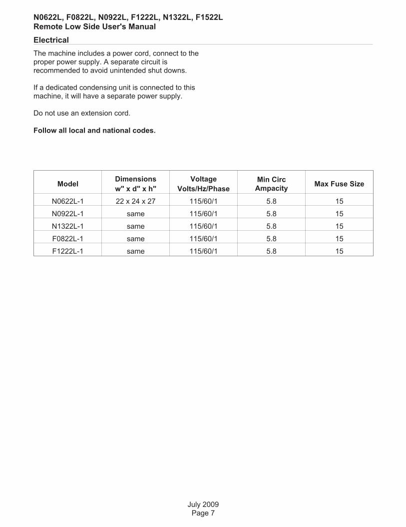
The machine includes a power cord, connect to theproper power supply. A separate circuit isrecommended to avoid unintended shut downs.
If a dedicated condensing unit is connected to thismachine, it will have a separate power supply.
Do not use an extension cord.
Follow all local and national codes.
July 2009Page 7
N0622L, F0822L, N0922L, F1222L, N1322L, F1522LRemote Low Side User's Manual
ModelDimensions
w" x d" x h"
Voltage
Volts/Hz/Phase
Min Circ
AmpacityMax Fuse Size
N0622L-1 22 x 24 x 27 115/60/1 5.8 15
N0922L-1 same 115/60/1 5.8 15
N1322L-1 same 115/60/1 5.8 15
F0822L-1 same 115/60/1 5.8 15
F1222L-1 same 115/60/1 5.8 15

Refrigeration
BTUH Capacity Requirements
Model BTUH
N0622L or F0822L 4,000
N0922L, F1222L 5,000
N1322L 7,200
Condensing Units
Model Use Condensing Unit
N0622L or F0822L NME654-RHS-A/C
N0922L or F1222L NME954-RHS-A/C
N1322L None - rack only
Remote low side models require connection to
a dedicated condensing unit or a rack system.
Recommended Tubing from Head to CondensingUnit
• Suction Line: 5/8" OD
• Liquid Line: 3/8" OD
Distance limits:
• Maximum distance between dedicatedcondensing unit and head: 75 feet.
• Condensing Unit Elevation over Ice MakingSection: 35 feet.
Note: Elevations greater than 20 feet requireinstallation of a suction line trap at the 10 footmark.
Ice Making Section
• Elevation over Condensing Unit: 15 feet.
Line Routing:
• Allowed: One rise after a drop.
• Allowed: One drop after a rise.
• Not Allowed: More than one rise after a drop
• Not Allowed: More than one drop after a rise
Roof Attachment
Install and attach the remote condensing unit to theroof of the building, using the methods andpractices of construction that conform to the localbuilding codes, including having a roofingcontractor secure the condenser to the roof.
Refrigeration Installation:
Connections
The liquid and suction fittings on the back of thecabinet are stubs. The liquid line size is 3/8" OD.The suction line size is 5/8" OD.
1. Recover holding charge
2. Cut the stubs off.
3. Braze line set tubing to each fitting. Sweep withdry nitrogen while brazing.
4. Dedicated condensing unit: Evacuate completesystem to 50 microns.
5. Open the ball valves.
Rack: The skills of a refrigeration technician arerequired to connect the ice machine to thebuilding’s refrigeration system.
Notes:
• R-404A models: 1.5 ounces of R-404Arefrigerant is in the system as a holdingcharge.
• Be sure the liquid connection is NOT inseries with another liquid line valve.
• Local Codes must be observed.
Dedicated condensing unit: Add refrigerant charge.Recommended starting field charge:
• N0622L or F0822L: 8 lb R-404A
• N0922L or F1222L: 8 lb R-404A
• N1322L: n/a - rack only
July 2009Page 8
N0622L, F0822L, N0922L, F1222L, N1322L, F1522LRemote Low Side User's Manual

Final Check List
After Connections
1. Wash out the bin. If desired, the interior of thebin could be sanitized.
2. Locate the ice scoop (if supplied) and have itavailable for use when needed.
Final Check List:
1. Is the unit located indoors in a controlledenvironment?
2. Is the unit located where it can receive adequatecooling air?
3. Has the correct electrical power been supplied tothe machine?
4. Have all the water supply connections beenmade?
5. Have all the drain connections been made?
6. Has the unit been leveled?
7. Have all unpacking materials and tape beenremoved?
8. Is the correct switch bezel installed in the trimstrip?
9. Is the water pressure adequate?
10. Have the drain connections been checked forleaks?
11. Has the bin interior been wiped clean orsanitized?
12. Have any water filter cartridges been replaced?
13. Have all required kits and adapters beenproperly installed?
14, Has the ice machine been properly connectedto the condensing unit or rack?
Control Operation
Use and Operation
Once started, the ice machine will automaticallymake ice until the bin or dispenser is full of ice.When ice level drops, the ice machine will resumemaking ice.
Caution: Do not place anything on top of the icemachine, including the ice scoop. Debris andmoisture from objects on top of the machine canwork their way into the cabinet and cause seriousdamage. Damage caused by foreign material is notcovered by warranty.
There are four indicator lights at the front of themachine that provide information on the conditionof the machine.
Indicator Lights:
• Power
• Status
• Water
• De-scale & Sanitize
There is front access to two switches – On and Off.
To switch the machine OFF, push and release theOff button. The machine will shut off at the end ofthe next cycle.
To switch the machine ON, push and release theOn button. The machine will go through a start upprocess and then resume ice making.
July 2009Page 9
N0622L, F0822L, N0922L, F1222L, N1322L, F1522LRemote Low Side User's Manual
Power
Status
NoWater
Time toClean
On
Off

Initial Start Up
1 Turn the water supply on.
2 Switch the electrical power on. Confirmvoltage is correct for the model.
3 Push and release the On button. Themachine will start up in about two minutes.The liquid line valve will open and liquidrefrigerant will flow into the machine. For theunits connected to a dedicated condensingunit, the resulting increase in suction pressurewill start the condensing unit.
4 Those units connected to a dedicatedcondensing unit will begin discharging warmair from the remote condenser. After about 5minutes, ice will begin to drop into the bin ordispenser.
5 Check the machine for unusual rattles.Tighten any loose screws, be sure no wiresare rubbing moving parts. Check for tubesthat rub.
6 The EPR valve should maintain low sidepressure at a minimum of 36 PSIG + or - 2PSIG.
Note: Machines will operate and make ice at thefactory EPR setting. For optimum performance,adjust the EPR to the settings in the chart below:
Model NumberScotsmanCondensing Unit
Rack
N0622L / F0822L Full open 30 PSIG
N0922L / F1222L Full open 30 PSIG
N1322L / F1522L Not specified 26 PSIG
Superheat will be 12oF, + or - a few degrees.
7 Fill out the warranty registration form andeither file it on line or mail it.
8 Notify the user of the maintenancerequirements and whom to call for service.
Maintenance
This ice machine needs five types of maintenance:
• Remote condensing units need theircondenser coils cleaned regularly.
• All models need scale removed from thewater system.
• All models require regular sanitization.
• All models require sensor cleaning.
• All models require a top bearing check.
Maintenance Frequency:
Scale removal. At least twice a year, in some waterconditions it might be every 3 months. The yellowDe-Scale & Sanitize light will switch on after a setperiod of time as a reminder. The default timeperiod is 6 months of power up time. There are 4available time period intervals: 1 year, 0 ordisabled, 6 months or 4 months.
Sanitizing: Every time the scale is removed or asoften as needed to maintain a sanitary unit.
Sensor Cleaning: Every time the scale is removed.
Top bearing check: At least twice a year or everytime the scale is removed.
Maintenance: Remote air cooled condenser
The condenser fins will occasionally need to becleaned of leaves, grease or other dirt. Check thecoil every time the ice machine is cleaned.
Maintenance: Exterior Panels
The front and side panels are durable stainlesssteel. Fingerprints, dust and grease will requirecleaning with a good quality stainless steel cleaner
Note: If using a sanitizer or a cleaner that containschlorine on the panels, after use be sure to washthe panels with clean water to remove chlorineresidue.
Maintenance: Water filters
If the machine has been connected to water filters,check the cartridges for the date they werereplaced or for the pressure on the gauge. Changecartridges if they’ve been installed more than 6months or if the pressure drops too much duringice making.
November 2009Page 10
N0622L, F0822L, N0922L, F1222L, N1322L, F1522LRemote Low Side User's Manual

Scale removal
Note: Following this procedure will reset thede-scale and sanitize light.
1 Remove front panel.
2 Push and release the Off button.
3 Remove ice from bin or dispenser.
4 Turn the water supply to the ice machine OFF.
5 Drain the water and evaporator bydisconnecting the leg of the hose connected tothe water sensor and draining it into the bin.Return the hose to its original position.
6 Remove the water reservoir cover.
7. Mix a solution of 8 ounces of Scotsman ClearOne Scale Remover and 3 quarts of 95-115degree F. potable water.
8. Pour the scale remover solution into thereservoir. Use a small cup for pouring.
9. Push and release the Clean button: the augerdrive motor and light are on, C is displayed andthe De-scale light blinks. After 20 minutes thecompressor will start.
10. Operate the machine and pour the scaleremover into the reservoir until it is all gone.
Keep the reservoir full. When all the scaleremover solution has been used, turn the watersupply back on. After 20 minutes of ice makingthe compressor and auger motor will shut off.
11. Turn the water supply to the ice machine OFF
12. Drain the water reservoir and evaporator bydisconnecting the leg of the hose connected tothe water sensor and draining it into the bin ora bucket. Return the hose to its originalposition. Discard or melt all ice made duringthe previous step.
13. To sanitize the water system, mix a locallyapproved sanitizing solution. An example of asanitizing solution is mixing one ounce of liquidhousehold bleach and two gallons of 95 – 115degree F. water.
14. Pour the sanitizing solution into the reservoir.
15. Push and release the On button.
16. Switch the water supply to the ice machine on.
17. Operate the machine for 20 minutes.
18. Push and release the Off button.
19. Wash the reservoir cover in the remainingsanitizing solution.
20. Return the reservoir cover to its normalposition.
21. Melt or discard all ice made during thesanitizing process.
22. Wash the inside of the ice storage bin with thesanitizing solution.
23. Push and release the On button.
24. Return the front panel to its original positionand secure with the original screws.
July 2009Page 11
N0622L, F0822L, N0922L, F1222L, N1322L, F1522LRemote Low Side User's Manual
Ice machine scale removercontains acids. Acids cancause burns.If concentrated cleanercomes in contact with skin,flush with water. If swallowed,do NOT induce vomiting.Give large amounts of wateror milk. Call Physicianimmediately. Keep out of thereach of children.

Check Top Bearing
This task should only be done by a qualifiedservice technician
The bearing in the breaker should be checked atleast two times per year.
Check the bearing by:
1 Removing the bail clamp and ice chute cover
2 Unscrewing the ice sweep
3 Removing the water shed & unscrewing thebreaker cover (left hand threads).
Inspect the top of the bearing. When new thegrease is white, over time some gray will appearover the rollers, that is normal. Add grease toreplace gray grease or if gaps between rollers arevisible. If grease is watery, all gray or rust is visible,have the bearing replaced. See the next page formore information.
Note: When checking the top bearing, alwaysinspect the drip pan for water seal leaks. If water ispresent in the drip pan, service the water seal andcheck the gear reducer's lubricant. See the nextpage.
July 2009Page 12
N0622L, F0822L, N0922L, F1222L, N1322L, F1522LRemote Low Side User's Manual
Bail Clamp

Bearing Service
This task should only be done by a qualifiedservice technician
If the bearing only needs grease, or to confirm thequality of the grease low in the bearing, injectgrease into the lower part of the bearing using
Scotsman grease needle pn 02-3559-01 andScotsman bearing grease cartridge, pnA36808-001. Be sure to inject grease evenly andthoroughly.
If the grease is uniformly white, no further action isneeded. If very gray, rusty, wet or has anyembedded metal, have the bearing replaced.
July 2009Page 13
N0622L, F0822L, N0922L, F1222L, N1322L, F1522LRemote Low Side User's Manual
Needle, pn02-3559-01
Bearing
Check Drip Pan For Water
Drip Pan
Change De-Scale Notification Interval
This feature is accessible only from standby(Status Light Off).
1. Press and hold Clean button for 3 seconds.
Starts the Time to Clean Adjustment State anddisplays the current time to clean setting.
2. Press the clean button repeatedly to cyclethrough the 4 possible settings:
• 1 year (8760 hours)
• 0 (disabled)
• 4 months (2920 hrs)
• 6 months (4380 hours) (default)

Options
Vari-Smart
Optional adjustable ice level control (KVS)
When this option is present there is an adjustmentpost and an additional indicator light to the right ofthe four indicator lights mentioned earlier. Theultrasonic ice level control allows the user to controlthe point that the ice machine will stop making icebefore the bin or dispenser is full. Reasons for thisinclude:
• Seasonal changes in ice used
• Planning to sanitize the bin
• Faster turnover for fresher ice
• Certain dispenser applications wheremaximum ice level is not desired
There are several positions the ice level can be setto, including Off (knob and label indicators linedup), where it fills the bin until the standard bincontrol shuts the machine off. See the kit’sinstructions for complete details.
Rotate the adjustment post to the desired ice level.The machine will fill up to that level and when itshuts off the indicator light next to the adjustmentpost will be On.
Note: The maximum fill positionis when the arrow on the knobpoints to the arrow on the label
Dispenser applications -
Nugget ice only:
Set the adjustment knob toeither the first or secondposition CW after themaximum fill position.
Smart-Board
Optional Advanced Feature Board (KSBU)
When this option is present there is an additionaldisplay panel in the area below the main controlboard. It is not visible when the front panel is on.
The Advanced Feature Board’s features include:
• Seven day programmable ice level settingwhen used with the optional Ultrasonic icelevel control
• Recording of machine operation
• Recall of malfunctions with the time theyoccurred.
Optional Remote Lock Out (KSL)
This add-on allows remote on-off control of themachine, and is generally installed by leasingcompanies. When the board has been remotelylocked out and shut off it must be reset by theperson or company that locked it out. It cannot bereset on site.
November 2009Page 14
N0622L, F0822L, N0922L, F1222L, N1322L, F1522LRemote Low Side User's Manual
02-4294-01 Rev. A.
Adjust Ice Level
Lower Bin
Full
Smart-Board Advanced Feature Control™
See Instructions for Available Features
34SEL
02-4293-01
ENTER
ESC
01/07
02-4294-01 Rev. A.
Adjust Ice Level
Lower Bin
Full
KVS
02-4294-01 Rev. A.
Adjust Ice Level
Lower Bin
Full

Service Diagnosis
July 2009Page 15
N0622L, F0822L, N0922L, F1222L, N1322L, F1522LRemote Low Side User's Manual
Symptom Probable Cause Possible Correction
No ice
No power
Check that ice machine andcondensing unit, if used, bothhave power. If power light is out,check transformer.
Code 3: No water Restore water
Status light is off Push and release ON switch
Code 1: No ice sensed
Check for ice flow down chute. ifvery slow or no ice being made,check water inlet tubing forrestriction; check for condensingunit or refrigeration systemfailure
Check auger motor for power, ifno power, check controllercomponent indicator light. Ifthere is power to the motor,check motor windings
Code 2: Auger motor draws toomany amps, controller shuts unitoff.
Check that liquid line valve shutsoff tightly
Check for damage to gearreducer or auger bearings.
Bin Eyes Blocked light is On
Ice is in the chute.
No ice in the chute. Checkposition of sensors, checksensors for scale build up
Everything is in operation, but norefrigeration effect
Check liquid line valve
Check condensing unit
Check TXV
Check refrigerant charge
Low ice making capacity
Scale build upRemove scale from evaporatorand water system
Suction tubing kinked Check suction tubing
Expansion valve superheatincorrect
Check superheat
What to do before calling for service
Normal Operation
Ice
The machine will make either flaked or nugget ice,depending upon the model. The ice will beproduced continuously until the bin is full.
Heat
Most heat is exhausted at the remote condensingunit or at the rack; the ice machine should notgenerate significant heat.
Noise
The ice machine will make noise when it is in icemaking mode. The gear reducer will producesound. Some ice making noise could also occur.These noises are all normal for this machine.
Reasons the machine might shut itself off:
• Lack of water.
• Does not make ice
• Auger motor overloaded
• Controller self test failure.
Check the following:
1. Has the water supply to the ice machine orbuilding been shut off? If yes, the ice machine will
automatically restart within minutes after waterbegins to flow to it.
2. Has power been shut off to the ice machine? Ifyes, the ice machine will automatically restart whenpower is restored.
3. Has someone shut the power off to the remotecondensing unit while the ice machine still hadpower? If yes, the ice machine may need to bemanually reset.
To Manually Reset the machine.
• Push and release the Off button.
• Push and release the On button.
To Shut the Machine Off:
1. Push and hold the Off button for 3 seconds oruntil the machine stops.
July 2009Page 16
N0622L, F0822L, N0922L, F1222L, N1322L, F1522LRemote Low Side User's Manual
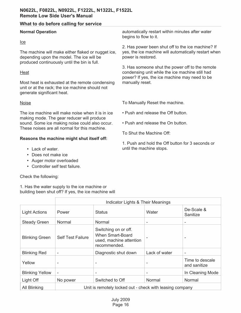
Indicator Lights & Their Meanings
Light Actions Power Status WaterDe-Scale &Sanitize
Steady Green Normal Normal - -
Blinking Green Self Test Failure
Switching on or off.
When Smart-Boardused, machine attentionrecommended.
- -
Blinking Red - Diagnostic shut down Lack of water -
Yellow - - -Time to descaleand sanitize
Blinking Yellow - - - In Cleaning Mode
Light Off No power Switched to Off Normal Normal
All Blinking Unit is remotely locked out - check with leasing company

SCOTSMAN ICE SYSTEMS
775 Corporate Woods Parkway, Vernon Hills, IL 60061
800-533-6006
www.scotsman-ice.com
17-3226-01