
USED FUEL TESTING TRANSPORTATION MODEL · Project Manager Signature on file ... ES-2100 Shipping...
40
USED FUEL TESTING TRANSPORTATION MODEL Prepared for U.S. Department of Energy Used Fuel Disposition Campaign Steven B. Ross, Ralph E. Best Steven J. Maheras, Philip J. Jensen Pacific Northwest National Laboratory Jeff England, Dan LeDuc Savannah River National Laboratory September 25, 2014 FCRD-UFD-2014-000326 PNNL-23668
-
Upload
duongquynh -
Category
Documents
-
view
214 -
download
0
Transcript of USED FUEL TESTING TRANSPORTATION MODEL · Project Manager Signature on file ... ES-2100 Shipping...

USED FUEL TESTING TRANSPORTATION MODEL
Prepared for U.S. Department of Energy
Used Fuel Disposition Campaign Steven B. Ross, Ralph E. Best
Steven J. Maheras, Philip J. Jensen Pacific Northwest National Laboratory
Jeff England, Dan LeDuc Savannah River National Laboratory
September 25, 2014 FCRD-UFD-2014-000326
PNNL-23668

DISCLAIMER
This information was prepared as an account of work sponsored by an agency of the U.S. Government. Neither the U.S. Government nor any agency thereof, nor any of their employees, makes any warranty, expressed or implied, or assumes any legal liability or responsibility for the accuracy, completeness, or usefulness, of any information, apparatus, product, or process disclosed, or represents that its use would not infringe privately owned rights. References herein to any specific commercial product, process, or service by trade name, trade mark, manufacturer, or otherwise, does not necessarily constitute or imply its endorsement,

Used Fuel Testing Transportation Model September 25, 2014 i
Reviewed by: Project Manager Signature on file 09/25/2014 ____________________________________________ Brady Hanson Date

Used Fuel Testing Transportation Model ii September 25, 2014

Used Fuel Testing Transportation Model September 25, 2014 iii
EXECUTIVE SUMMARY
This report is in fulfillment of milestone M3FT-14PN0812031 “Used Fuel Testing Transportation Modeling” under work package FT-14PN081303.
This report identifies shipping packages/casks that might be used by the Used Nuclear Fuel Disposition Campaign Program (UFDC) to ship fuel rods and pieces of fuel rods taken from high-burnup used nuclear fuel (UNF) assemblies to and between research facilities for purposes of evaluation and testing. Also identified are the actions that would need to be taken, if any, to obtain U.S. Nuclear Regulatory Commission (NRC) or other regulatory authority approval to use each of the packages and/or shipping casks for this purpose.
The primary focus for this report is work initiated in FY 2014 to prepare an application to update the certificate of compliance (CoC) for the U.S. Department of Energy’s (DOE’s) Model 9977 package. Because of interest expressed by the UFDC, the planned application to update the CoC for the Model 9977 package will also request authorization to use the package to ship 16-in.-long fuel rod segments taken from high-burnup pressurized-water-reactor (PWR) fuel assemblies.
The remainder of the report identifies and evaluates the potential use by the UFDC of other models of shipping casks and packaging to ship full-length commercial nuclear power reactor fuel rods and segments of fuel rods. This analysis lists these other casks and packages with respect to how well their use would support the UFDC research and development testing objectives. The consideration of a new package was considered cost prohibitive for the low number of shipments expected for this program. To support the evaluation, Section 1 of this report provides background on the UFDC and the UFDC objectives that this effort would support. Section 2 briefly describes the testing that would be accomplished by identifying a package for transport of high-burnup fuel segments. Section 3 briefly discusses that the capabilities of the shipping and receiving facilities will be evaluated as the needs of the program are better defined. Section 4 describes that packaging options beginning with the Model 9977 for fuel segments and also discussing options for shipping full-length fuel assemblies. Section 5 presents a summary of the findings of this report along with potential future testing decisions.
Used Fuel Testing Transportation Model iv September 25, 2014


Used Fuel Testing Transportation Model September 25, 2014
CONTENTS
EXECUTIVE SUMMARY ........................................................................................................... iii
ACRONYMS .................................................................................................................................. ii
1. Introduction ............................................................................................................................1
2. Used Fuel Disposition Testing ...............................................................................................3
2.1 National Laboratory Testing Scope ..............................................................................3
2.2 Used Fuel Transportation Requirements ......................................................................3
3. Shipping and Receiving Facilities Capabilities ......................................................................5
4. TRANSPORTATION OPTIONS FOR USED NUCLEAR FUEL .......................................7
4.1 Fuel Characteristics ......................................................................................................7
4.2 Model 9977 Package .....................................................................................................7
4.3 Evaluation of other Transportation Packages .............................................................10 4.3.1 HBU Full-length Fuel Rods ............................................................................12 4.3.2 HBU Fuel Rod Segments ................................................................................14
4.4 Shipping Options Comparison ....................................................................................21
4.5 Activities Involved in the Transport of UNF Samples ...............................................23
5. SUMMARY and Future Efforts ...........................................................................................25
6. REFERENCES .....................................................................................................................27

Used Fuel Testing Transportation Model September 25, 2014 i
FIGURES
4-1. Model 9977 Shipping Package ............................................................................................... 8
4-2. NAC LWT Shipping Cask (printed with permission from NAC International) .................. 13
4-3. T-3 Shipping Cask ................................................................................................................ 13
4-4. BEA Research Reactor Cask (printed with permission from AREVA Federal Services) ......................................................................................................................... 15
4-5. Model 2000 Shipping Cask .................................................................................................. 16
4-6. ES-2100 Shipping Container ................................................................................................ 17
4-7. Beneficial Uses Shipping System Cask ................................................................................ 18
4-8. 10-160B Cask ....................................................................................................................... 19
4-9. CNS 8-120B Cask ................................................................................................................ 21
TABLES
4-1. Transportation Casks Considered ......................................................................................... 11
4-2. 10-160B Cask Dimensions ................................................................................................... 19
4-3. Comparison of Casks to Support UFD Research and Development Testing Options ......... 22

Used Fuel Testing Transportation Model ii September 25, 2014
ACRONYMS
ANL Argonne National Laboratory
ASME American Society of Mechanical Engineers
ASTM ASTM International (formerly American Society for Testing and Materials)
ATR Advanced Test Reactor
BEA Battelle Energy Alliance
BRR BEA Research Reactor
BWR boiling water reactor
BUSS Beneficial Use Shipping System
CoC certificate of compliance
CV containment vessel
DOE U.S. Department of Energy
GWd/MTU gigawatt-days per metric ton of uranium
HBU high-burnup nuclear fuel
INL Idaho National Laboratory
LWR light water reactor
LWT legal weight truck
NAC NAC International (formerly Nuclear Assurance Corporation)
MITR Massachusetts Institute of Technology Nuclear Reactor
MURR Missouri University Research Reactor
MWd/MTU megawatt-days per metric ton of uranium
NNSA National Nuclear Security Administration
NRC U.S. Nuclear Regulatory Commission
ORNL Oak Ridge National Laboratory
PNNL Pacific Northwest National Laboratory
PWR pressurized water reactor
R&D research and development
ROM rough order of magnitude
SAR safety analysis report
SARP safety analysis report for packaging
SET separate effects testing
SRNL Savannah River National Laboratory
SS Stainless Steel
SST small-scale testing

Used Fuel Testing Transportation Model September 25, 2014 iii
TRIGA Training, Research, Isotopes, General Atomics Reactor
TRU Transuranic
UFDC Used Fuel Disposition Campaign
UNF used nuclear fuel


Used Fuel Testing Transportation Model September 25, 2014 1
USED FUEL TESTING TRANSPORTATION MODEL
1. INTRODUCTION
The U.S. Department of Energy’s (DOE’s) Used Fuel Disposition Campaign (UFDC) Program plans to transport high-burnup nuclear fuel (burnup exceeding 45 gigawatt-days per metric ton of uranium [GWd/MTU]) from domestic nuclear power plants to DOE national laboratory facilities, and between laboratory facilities for purposes of evaluation and testing. The evaluation and testing of high-burnup used nuclear fuel (UNF) is integral to DOE initiatives to collect information that is useful in determining the integrity of fuel cladding for safe transportation of the fuel in the future, and for determining the effects of aging on the integrity of UNF subjected to extended storage and subsequent transportation. The UFDC began identifying the research and development (R&D) opportunities (Hanson 2012) necessary to establish the licensing basis for extended storage; including storage of high-burnup light water reactor (LWR) fuels. These R&D needs have been evaluated using a requirements analysis methodology to define the programmatic capabilities required. An overview of spent nuclear fuel transportation is provided by the Electric Power Research Institute (EPRI 2004).
This work addresses the R&D opportunities associated with research data for high-burnup fuel samples. More research is needed because limited information is available on the properties of high-burnup fuel, and because much of the fuel currently discharged from today’s reactors exceeds this burnup threshold. As the burnup of fuel increases, a number of changes occur that may affect the performance of the fuel, cladding, and assembly hardware in storage and transportation. These changes include increased cladding corrosion layer thickness, increased cladding hydrogen content, increased cladding creep strains, increased fission gas release, and the formation of the high-burnup structure at the surface of the fuel pellets. One of the focuses of the UFDC will be to obtain the data on high-burnup fuel and the newer cladding materials and develop a technical basis for determining how the storage and transportation systems perform to address the growing inventory of high-burnup fuel.
To meet UFD’s research objectives, including establishing the licensing basis for extended storage, this report evaluates multiple options for transporting used fuel to and between research facilities. Specifically, the report identifies for evaluation the transportation packages and shipping casks that are candidates to transport used nuclear fuel to support the research program’s objectives. The report lists the transportation packages and shipping casks based on factors that gauge their viability for use. The report also identifies unresolved transportation issues for fuel sample transport between laboratories for separate effects testing.
The UFDC Program plans to partner with the U.S. commercial nuclear industry to identify and obtain UNF for testing. Individual fuel rods are needed for both separate effects testing (SET) and small-scale testing (SST), whereas entire assemblies may be necessary for SST. It is assumed that the UFDC Program would need to provide funding to the owner(s) of suitable transportation casks to obtain amendments to the U.S. Nuclear Regulatory Commission (NRC)/DOE certificates of compliance (CoCs) for the casks, if needed, and use the casks to ship the selected high-burnup nuclear fuel rods and/or assemblies to a national laboratory. It is

Used Fuel Testing Transportation Model 2 September 25, 2014
possible that the privately owned casks could also be used to ship segments of high-burnup fuel rods between laboratory facilities. The Idaho National Laboratory (INL) is the only national laboratory capable of receiving and handling an entire fuel assembly. This study assumes all fuel, rods, or assemblies will initially be sent from the commercial nuclear power plant(s) to INL.
The high-burnup UNF rods or assemblies will be characterized by visual examination, reactor records, and other physical examinations at the commercial nuclear power plant(s) before shipment. Following delivery to the INL hot cell facility, the UFDC Program researchers plan to further characterize the fuel and then segment a selection of high-burnup fuel rods into 6- to 16-in.-long sections (assumed for the purposes of this study, based on the sizes necessary for the currently planned SET) so that the nuclear fuel and cladding can be more easily examined and transported to other laboratories for independent and laboratory-specific SET. It is assumed Pacific Northwest National Laboratory (PNNL), Oak Ridge National Laboratory (ORNL), and Savannah River National Laboratory (SRNL) will be capable of receiving segments of UNF with the fuel still in the cladding. The researchers also plan to ship sections of cladding with the nuclear fuel removed to Argonne National Laboratory (ANL) for SET.
While options for transporting full-length fuel rods or assemblies will be limited to a few currently licensed casks, options are available for selecting packaging or casks to transport segments of fuel rods. Selection from among the options will depend on the quantity, burnup, cooling time and size of segments to be shipped. As a follow-on to the letter report prepared in FY 2013 (Ross et al. 2013), this report was prepared to identify options for packaging and casks to transport used fuel that facilitate the greatest possible range of samples that can be used for testing. To that end, this report focuses on the objective of shipping used fuel segments, but also discusses the available options for selecting casks to ship full-length high-burnup used fuel rods.
Used Fuel Testing Transportation Model September 25, 2014 3
2. USED FUEL DISPOSITION TESTING
The testing that will be accomplished under the UFD R&D testing program includes:
Fuel Examinations
– Nondestructive examinations of fuel assemblies and individual rods
○ visual, leak testing, dimensional measurements, eddy current flaw detection, among others
– Destructive examinations
○ fission gas analysis
○ cladding mechanical properties
○ cladding microstructure examinations
○ fuel pellet characterizations.
As currently envisioned, the program will be conducted in two major phases: the first to formulate a technical basis for extended dry fuel storage; and the second is to validate that basis. Formulating the technical basis will involve initial testing of fuel rods, rod segments, and cladding. Validating the basis will be dependent on periodic evaluations of the dry stored fuels, rod segments, cladding, and storage systems at specified time intervals.
Formulating the technical basis will require receiving and examining a moderate amount of used fuel rods representing a sampling of typical fuels and storage system components. The fuel rods will require sectioning along with fission gas analysis as they are being sized. The resulting fuel rod samples will be tested, based on the R&D needs required to establish the basis.
For validation, an assortment of fuel assemblies will have a baseline examination and then be stored in various dry storage systems for a predetermined amount of time. At a specified time, some of the fuel assemblies will be removed from the dry storage systems and undergo examination and testing. Some fuel rods will be extracted from these assemblies for detailed testing similar to the initial tests performed to formulate the basis. Techniques to induce accelerated aging are envisioned. Intact fuel would then be returned to dry storage for further aging with the intent of subsequent re-examinations at specified time intervals.
2.1 National Laboratory Testing Scope
The specific testing to be performed at national laboratories will be described in a future document.
2.2 Used Fuel Transportation Requirements
The evaluation of shipping casks that could be used to transport full-length high-burnup fuel rods assumed the rods would be removed from a 17x17 pressurized water reactor (PWR) fuel assembly. To bound the radiation and radionuclide contents for individual rods, the evaluations

Used Fuel Testing Transportation Model 4 September 25, 2014
assumed that the burnup of the uranium fuel in the rods would be as high as 80,000 megawatt-days per metric ton of uranium (MWd/MTU), the cooling time would be as low as 5 years, and the initial enrichment of the fuel would be 5wt% 235U. The evaluation assumed that as many as 25 rods could be transported in a cask.
The evaluation of packages that could be used to transport segments of high-burnup fuel rods assumed the segments would be taken from fuel rods from a 17x17 PWR fuel assembly and could be up to 16 in. long. To bound the radiation and radionuclide contents for a single package in a shipment, the evaluations assumed that the burnup of the fuel in each individual segment could be as high as 80,000 MWd/MTU, the cooling time would be as low as 5 years, and the initial enrichment of the fuel would be 5wt% 235U. The number of segments that could be transported in a single package will be determined. The number of samples required for evaluations and testing at the research facilities will be determined by the specific tests being conducted.
Used Fuel Testing Transportation Model September 25, 2014 5
3. SHIPPING AND RECEIVING FACILITIES CAPABILITIES
The specific capabilities of each of the potential shipping and received facilities will be investigated as the needs of the program are better defined. Based on past operating experience of the facilities it is expected they will have capability to handle the packages and casks described in this report.

Used Fuel Testing Transportation Model 6 September 25, 2014

Used Fuel Testing Transportation Model September 25, 2014 7
4. TRANSPORTATION OPTIONS FOR USED NUCLEAR FUEL
This section describes the preferred option, the DOE Model 9977 package, for a transportation package for segments of used nuclear fuel rods. Also discussed is the rationale for selecting the Model 9977 package for this purpose, and the planned request for modification to the package’s safety analysis report for packaging (SARP) (DOE 2006) and CoC (DOE 2013b) to accommodate segments of high-burnup used nuclear fuel rods. The Model 9977 is a drum-sized package that will provide the UFDC Program a practical and economical means to transport segments of high-burnup UNF fuel rods up to 16 in. long.
Also reviewed are casks initially identified in the UFD transportation modeling letter-report for transporting long sections of fuel rods and full-length fuel rods (Ross et al. 2013). The reviewed casks are described, including limitations on contents currently authorized by their CoCs. Lastly, for each of these casks, the feasibility of obtaining regulatory approval to use the cask to transport high-burnup used nuclear fuel is considered.
4.1 Fuel Characteristics
The fuel to be analyzed by the UFD research testing program will be high-burnup fuel rods removed from fuel assemblies discharged from a commercial nuclear power reactor. The fuel rods will be shipped to the host laboratory where they will be received and cut into segments. Some of the fuel rod segments will be prepared for subsequent shipment to other laboratories. A range of rod segment lengths up to 16 in. shipped from the host facility provides flexibility to select a transportation package and also for the destination facilities, regarding the size of rod segments they could elect to receive. The number of rod segments that will be needed by a facility will be determined based on the types of tests to be conducted and the range of characteristics of the used fuel to be tested. The expected burnup of the fuel will be greater than 45,000 MWd/MTU. For purposes of evaluating transportation casks and packaging PWR fuel having a burnup of 80,000 MWd/MTU, 5% enrichment and 5-year cooling was chosen.
4.2 Model 9977 Package
The Model 9977 Package (Offsite Transportation Certificate No. USA/9977/B(M)F-96 (NNSA) (DOE 2013b), whose certificate expires on 9/30/2017, is a radioactive materials transportation package used by DOE and the National Nuclear Security Administration (NNSA) to transport radioactive components. More than 50 of the packages have been constructed. The Model 9977 Package (see Figure 4-1) outer container is a 35-gallon drum modified with a bolted-flange closure. The drum shell and liner are fabricated of 18-gauge Type 304L stainless steel (SS). The drum is designed, analyzed, and fabricated in accordance with Section III, Subsection NF of the ASME Boiler & Pressure Vessel Code (ASME 2013). Vent holes are drilled at multiple locations around the drum, and all of the holes are filled with appropriately sized Caplug®a fusible plastic plugs.
a A registered trademark of Caplugs, Buffalo, New York.

Used Fuel Testing Transportation Model 8 September 25, 2014
Figure 4-1. Model 9977 Shipping Package
The top portion of the drum incorporates a 3/16-in.-thick reinforcing rim (vertical flange) and reinforces the drum head and protects both the closure lid and bolts during hypothetical accident condition events. The rim includes eight, 1-in. diameter drain holes that are qualified as package lifting and tie-down points. The drum bottom includes a rolled “wear ring,” 0.060-in.-thick by ¾-inch inside diameter attached by welds external to the drum shell.
5/8-inch Drum Flange Bolt (78)
35 Gallon SS Drum
Drum Rim with TAD and Drain and Tie-Down Holes
Caplug®
Bottom Load Distribution Fixture
General Plastics FR-3716 Polyurethane Foam
Ceramic Vermiculite TRY-19® Block
Ceramic Min-K 2000®
6-inch ID Containment Vessel Top Load
Distribution Fixture
Fiberfrax® Insulation
Sanitary Drum Bottom with Wear Ring

Used Fuel Testing Transportation Model September 25, 2014 9
The drum closure lid is fabricated from 1/8-in.-thick Type 304L SS plate and fastened with eight heavy hex-head bolts with washers. The bolt heads are drilled through with a 1/8-inch hole to received tamper-indicating devices (TIDs). The lid top and lid bottom chambers are fabricated from 18-gauge and 14-gauge Type 304L SS, respectively. Four holes through the lid plate allow the lid top and lid bottom volumes to exchange gases. The lid top chamber is vented by four holes covered with Caplug® fusible plastic plugs.
The 9977 is designed with a containment vessel (CV) with a nominal inner diameter of 6 in. (6CV). The 6CV is a stainless steel pressure vessel designed, analyzed and fabricated in accordance with Section III, Subsection NB of the ASME Code. The 6CV is fabricated from 6-in., Schedule 40, seamless, Type 304L SS pipe (0.280-in. nominal wall). A support skirt to stand the 6CV vertically is formed from a short segment of 5-in., Schedule 40 Type 304L SS pipe welded to the base. Two rectangular notches milled into the bottom edge of the skirt can engage a rectangular key to prevent vessel rotation during removal and installation of the closure assembly.
The 6CV closure assembly consists of a Type 304L SS cone-seal plug shaped in part like a truncated cone and a threaded cone-seal nut made from Nitronic 60 SS. To minimize the potential for thread galling, the cone-seal nut and the containment vessel body are made from dissimilar materials. Two O-ring grooves (outer and inner) are machined in the face of the external cone-seal plug with Viton® GLT/GLT-S Ob rings fit into these grooves to complete the leaktight closure assembly.
For operator safety, a 0.094-in. diameter vent hole is located in the stayed head between the threads and the internal sealing surface. The vent hole is clocked 90° from the notches in the vessel support skirt. Unscrewing the cone-seal nut a few turns will unseat the cone-seal plug from the internal cone-seal surface and route any pressurized gases from the CV through the vent hole.
A leak-test port is incorporated into the cone-seal plug and connected by a drilled radial passage to the annular volume between the two O ring grooves in the cone-seal plug. The leak-test port provides a means of verifying proper assembly of the vessel closure and is itself closed by the leak-test port plug. The vessel containment boundary is formed by the vessel body weldment, the cone seal plug, the leak test port plug, and the outer O ring. The internal volume of a closed 6CV is approximately 608 in.3. The nominal assembly weight is 52.3 lb and nominal overall length is 24.03 in. The usable cavity of the 6CV is a minimum of 20.25 in. deep with a minimum diameter of 5.95 in.
The top and bottom load distribution fixtures are made from 6061 T6 aluminum round bar and fit within the drum liner cavity, above and below the 6CV. These center the 6CV in the liner, stiffen the package in the radial direction, and distribute loads away from the 6CV.
Neither current 9977 materials nor component geometry provides significant radiation shielding. Dose rate attenuation is provided primarily by the distance between the source and points
b Viton® is a registered trademark of the E.I. du Pont de Nemours and Company,

Used Fuel Testing Transportation Model 10 September 25, 2014
external to the package with minimal attenuation provided by the materials of the 6CV, Fiberfrax®c, polyurethane foam, and the drum.
To increase the shielding capability of the 9977 the heat dissipation sleeve (completely around 6CV ), currently made from 6061 T6 aluminum, will be replaced with a duplicate part made of tungsten. A tungsten-shielded container will be placed inside the 6CV to reduce dose rate for the used fuel content. The 9977 has already used containers specifically designed to provide additional neutron or photon shielding inside the 6CV to reduce the dose rate.
The 9977 design does not incorporate materials or other design features (e.g., neutron absorbers, flux traps, spacers) specifically for the purpose of poisoning or moderating neutron radiation. Subcriticality is ensured by limiting the package fissile material mass and/or through the use of content components that provide the volume and spacing control necessary to ensure subcriticality.
The Model 9977 SARP (DOE 2006) is being revised. The revision includes analysis of the performance of the package when it is used to ship segments of used nuclear fuel rods. The revision includes a tungsten liner and tungsten shielded container to provide increased radiation shielding for UNF and other planned radioactive material contents. A tungsten pig, specific to the fuel rod content, would need to be procured to enable use of a package to transport fuel-rod segments. Regulatory approval of the updated SARP containing revisions to the design and contents for the Model 9977 package and issue of a revised CoC are expected early in calendar year 2015.
4.3 Evaluation of other Transportation Packages
Table 4.1 lists the transportation casks from Ross et al. (2013). The table includes the identification numbers for each of the casks and applicable expiration dates of the casks’ CoCs. Table 4.1 also presents the estimated number of each of the listed casks available for use and briefly summarizes the authorized contents listed in the CoCs. (Note: Some of the listed casks do not currently authorize used nuclear fuel contents. An application to the regulatory authority would be required to use these casks to ship used nuclear fuel contents.) Also, the packages presented in Table 4.1 are organized by which packages could ship full-length fuel rods, fuel rod segments, or both. No attempt was made at ranking the packages in Table 4.1; however, for fuel-length fuel rods the NAC-LWT cask can ship high-burnup used nuclear fuel (HBU) today.
This section presents an evaluation of the viability of a selection of shipping casks to transport high-burnup UNF fuel rods and segments of fuel rods to support the UFD R&D objectives. Included in this evaluation are a consideration of the range of burnup, number of samples, and length of samples that could be transported. Costs are also addressed including the cost of new applications that may be needed to revise CoCs to allow transport of UNF. Costs to prepare safety analyses and obtain regulatory approval for changes to CcCs that authorize use of the packages to transport UNF rod segments are presented as rough order of magnitude (ROM) estimates. ROM estimates of costs are based on the report authors’ judgment and indicate that detailed analyses of the potential costs have not been performed.
c Fiberfrax® is a registered trademark of the Unifrax Corporation in Niagara Falls, New York

Used Fuel Testing Transportation Model September 25, 2014 11
In general, the cost to obtain regulatory authorization to use a cask or package to transport UNF segments is believed to fall in the range of $250,000 to $3 million. The lower end of the range, $250,000, represents the cost to obtain authorization to use a package having a CoC that currently authorizes transport of sections of used nuclear fuel rods but does not authorize contents having the range of properties of UNF fuel rod samples that may be transported for the UFD Program. The upper end of the range, $3 million, represents the cost that would be incurred to obtain authorization to use a package that has an expired CoC and has not been previously approved for the transport of fissile material.
Table 4-1. Transportation Casks Considered
Cask Package ID Number
CoC Expiration Date
Packages Available
CoC Contents
HBU Full Length Fuel Rods or Fuel Segments NAC-LWT USA/9225/B(U)
F–96 (NRC 2013)
2/28/15 5 25, full-length, high burnup fuel rods. 14 of the fuel rods can be classified as damaged
T-3 USA/9132/B(M)F (DOE 2008)
12/31/2013 (termination of
NRC CoC 1/10/07)
3 Designed for sodium bonded and cooled Fast Fuel Test Facility (FFTF) nuclear fuel
HBU Fuel Segments BEA Research Reactor (BRR)
USA/9341/B(U)F–96 (NRC 2011a)
1/22/15 1 19 irradiated TRIGA fuel elements
GE Model 2000
USA/9228/B(U)F(NRC 2011b)
5/31/16 1 Includes irradiated fuel rods which may be cut or segmented
ES-2100 DOE/NNSA/2000302/B(U)F (DOE 2002)
1/31/2008 125 at DOE Y-12 facility
Type B quantities of nuclear weapons radioactive material
BUSS R-1 USA/9511/B(U) (NRC 1991)
3/31/2008 1 (not verified) Cs/Sr Capsules
10-160B USA/9204/B(U)F–96 (DOE 2012)
10/31/15 2 Casks in service one owned by
DOE
200 thermal watt limit, TRU special form fissile material in secondary containers, RH-TRU, radioactive sources, TRU material in secondary containers
8-120B USA/9168/B(U) (DOE 2013a)
6/30/15 4 100 thermal watts waste material. Not currently certified for fissile material contents.
BEA = Battelle Energy Alliance, BUSS = Beneficial Uses Shipping System, CoC = certificate of compliance, DOE = U.S. Department of Energy, ID = identification, NNSA = National Nuclear Security Administration, NRC = U.S. Nuclear Regulatory Commission, RH=remote handled TRIGA = Training, Research ,Isotopes, General Atomics (research reactor), TRU = transuranic
Although not part of this effort, in order to fully describe the acquisition and use of the transport cask(s)/package(s) described in Table 4-1 it will be necessary to collect the following information regarding each cask/package:
design descriptions of the casks/packages

Used Fuel Testing Transportation Model 12 September 25, 2014
CoCs issued by regulatory authorities
preparation costs of SAR/SARP, submittal to NRC (or other certifying agency), and technical interactions with NRC (or other certifying agency) to obtain CoCs for high burnup used nuclear fuel (fuel rods, rod segments, cladding segments) contents
assessments of the scope of tasks to obtain regulatory authorization for use of each candidate cask/package to transport the specified UNF (and fuel cladding) contents
shipping and receiving facility procedures
descriptions of ancillary equipment needed for facilities to handle, load, and unload the casks/packages.
current condition, location, and ownership of the casks/packages
contract considerations for casks/packages owned by industry
requirements for return following use of casks/packages owned by other government agencies or other organizations within DOE.
4.3.1 HBU Full-length Fuel Rods
4.3.1.1 NAC-LWT Cask
The NAC-LWT Cask (USA/9225/B(U)F–96) is a steel-encased, lead-shielded shipping cask having a forged stainless steel lid and 12 closure bolts, tailored payload baskets to the contents being shipped, water-ethylene-glycol neutron shield, and top- and bottom-end impact limiters (Figure 4-2). The cask is designed to transport one PWR assembly or two boiling water reactor (BWR) assemblies by truck. Five of the legal weight truck (LWT) casks are owned and offered for use by NAC International, based in Norcross, Georgia.
The LWT cask’s CoC authorizes its use to ship research reactor spent fuel, nuclear power plant spent fuel assemblies and fuel rods, and other irradiated materials. When used to ship commercial nuclear power reactor fuel rods, the maximum burnup authorized by the CoC is 80,000 MWd/MTU. For fuel assemblies, the maximum authorized burnup is 35,000 MWd/MTU. The CoC authorizes shipment of up to 25 individual fuel rods with as many as 14 of the rods being classified as damaged. Damaged rods may include fuel debris, particles, loose pellets, and fragmented rods. Damaged fuel rods must be placed in a fuel rod insert or individual failed fuel rod capsules prior to placement in the fuel rod insert. The fuel rod insert must be transported in a PWR/BWR transport canister in the cask’s PWR basket.
The cask can be loaded wet in a pool or dry in hot cell facilities or facilities with small pools and limited crane capacities.

Used Fuel Testing Transportation Model September 25, 2014 13
Figure 4-2. NAC LWT Shipping Cask (printed with permission from NAC International)
4.3.1.2 T-3 Cask
The T-3 Shipping Cask (USA/9132/B(M)F) (Figure 4-3) is currently stored at the Fast Flux Test Facility near the Hanford Site in southeastern Washington state. Three T-3 Shipping Casks are available. The DOE CoC expires in January 2019. The authorized contents include UO2 fuel rods and a maximum of 1400 thermal watts. The NRC CoC expired in January 2010. The NRC and DOE certificates are equivalent and either the DOE CoC or the NRC CoC can be used by the U.S. Department of Transportation to authorize shipment.
Figure 4-3. T-3 Shipping Cask
The T-3 cask is a stainless steel and lead-shielded irradiated fuel shipping package (cask). The cask is a right circular cylinder with upper and lower steel-encased rigid polyurethane foam (0.32 g/cm3, 20 lb/ft3) impact limiters. The overall dimensions are 541.5 cm (213.2 in.) in length and 132.1 cm (52 in.) in diameter. The cask without the impact limiters measures 450.1 cm (177.2 in.) in length and 67.16 cm (26.44 in.) in diameter. The outer cask shell is composed of a 2.54-cm- (1-in.-) thick SS shell overlayed with a 10-gauge stainless steel cover. Between these

Used Fuel Testing Transportation Model 14 September 25, 2014
two materials is a 0.2-cm (0 .08-in.) diameter wire wrap, providing an air gap for additional thermal protection. The inner shell (containment vessel) is a standard seamless SS Schedule 40 pipe having an outside diameter of 21.9 cm (8.625 in.) with a nominal wall thickness of 0.82 cm (0.322 in.). The annular space between the inner and outer shells is filled with lead having a thickness of approximately 20.3 cm (8 in.).
Before a T-3 package could be used to ship full-length high-burnup commercial nuclear fuel rods and/or segments of fuel rods, an addendum to the cask’s SARP would need to be prepared and submitted to the regulatory authority for review and approval to obtain a revision to the cask’s CoC. As part of this effort the ability of the T-3 design to accommodate high-burnup fuel needs to be evaluated. The ROM estimate for SARP Addendum, costs to return a T-3 cask to service, and costs of regulatory review to obtain a revised CoC is between $1 million and $2 million.
4.3.2 HBU Fuel Rod Segments
The packages presented in this section would require modifications to accommodate HBU fuel. However, all of the following packages are not sized to accommodate a full-length fuel rod independent of whether is an authorized content based on the CoC.
4.3.2.1 BEA Research Reactor Cask
The Battelle Energy Alliance (BEA) Research Reactor (BRR) Cask is a package used to transport fuel elements that have been irradiated in various test and research reactors. The package cavity could accommodate fuel segments, but not full-length fuel rods. One BEA Research Reactor LWT cask (USA/9341/B(U)F–96) is owned by the DOE and operated from INL by the BEA. AREVA Federal Services, LLC is the designer and NRC licensee for the cask. The cask consists of a payload basket (specific design for the fuel being transported), a lead-shielded cask body, a separate, removable upper shield plug, a closure lid, 12 closure bolts, and upper and lower impact limiters containing polyurethane foam. Except for the closure bolts and impact limiter attachments, the cask is of welded construction, using Type 304 austenitic stainless steel (Figure 4-4). The cask is certified for the transportation of irradiated nuclear fuel elements from the Missouri University Research Reactor (MURR), Massachusetts Institute of Technology Nuclear Reactor (MITR), Advanced Test Reactor (ATR), and Training, Research, Isotopes, General Atomics (TRIGA) reactors. The cask may be loaded and unloaded under water in a pool or dry in a hot cell.
The cask is composed of a lead–shielded body, payload basket, an upper shield plug, a closure lid and seals, upper and lower impact limiters, and uses ASTM Type 304 SS as its primary structural material. The cask is a right circular cylinder 77.1 in. long and 38 in. in diameter, not including the impact limiter attachments and the thermal shield. Lead shielding is located between two circular shells, in the lower-end structure, and in the shield plug. The payload cavity has a diameter of 16 in. and a length of 54 in. There are four baskets used with the package, one for each type of fuel transported. The baskets are made from welded construction using ASTM Type 304 SS in plate, bar, pipe, and tubular forms. Each basket has a diameter of 15.63 in. and a length of 53.45 in., and features a number of cavities that fit the size and shape of the fuel. It would be expected that this package can accommodate HBU fuel segments.

Used Fuel Testing Transportation Model September 25, 2014 15
The current CoC, which was issued August 22, 2011, expires on January 22, 2015. Supplements to the CoC, each of which authorized new kinds of contents, were issued August 6, 2009, November 5, 2009, June 4, 2010, December 16, 2010, and June 24, 2011.
The BRR CoC authorizes transport of up to 8 irradiated MURR fuel elements, up to 11 irradiated MITR–II fuel elements, up to 8 irradiated ATR fuel elements, or up to 19 irradiated TRIGA fuel elements. A CoC revision would be required before the cask could be used to transport commercial PWR fuel rod segments. The cask cavity is shorter than those for the NAC LWT cask, TN-LC cask, or T3 cask. It is probable that the current SARP and CoC could accommodate PWR rod segments and HBU segments are bounded by existing analysis in the SARP and CoC. However, that would need to be verified. For example, the maximum TRIGA fuel burnup that can be accommodated is approximately 340,000 MWd/MTU and the maximum quantity of plutonium contents authorized for transport in the cask is 873 Ci.
Supplemental analysis and an application to NRC for an amendment to the CoC to obtain approval to use the BRR cask to ship high-burnup commercial nuclear power reactor fuel rod segments would be required. The ROM estimate to prepare an amendment to the BRR’s Safety Analysis Report and obtain NRC review and a revised CoC that authorizes transport of high-burnup fuel rod segments is $750,000.
Figure 4-4. BEA Research Reactor Cask (printed with permission from AREVA Federal Services)
4.3.2.2 GE Model 2000 Cask
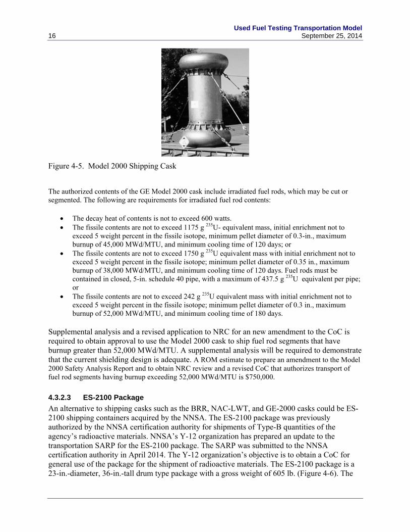
The Model 2000 Shipping Cask (USA/9228/B(U)F-96) is owned by GE-Hitachi Nuclear Energy Americas, LLC, which has its offices in Wilmington, North Carolina. The cask’s body (shielded containment vessel) is constructed of steel shells encasing lead radiation shielding. Shown in Figure 4-5, for transport, the cask body is situated within a double-walled overpack with toroidal-shell impact limiters at each end. The CoC for the Model 2000 Shipping Cask authorizes its use to transport irradiated nuclear fuel, radioactive (contaminated and activated) nuclear reactor hardware, and radioactive waste. The cask is authorized for the shipment of LWR fuel rod segments and fuel pellets having burnups up to 52,000 MWd/MTU.
Used Fuel Testing Transportation Model 16 September 25, 2014
Figure 4-5. Model 2000 Shipping Cask
The authorized contents of the GE Model 2000 cask include irradiated fuel rods, which may be cut or segmented. The following are requirements for irradiated fuel rod contents:
The decay heat of contents is not to exceed 600 watts. The fissile contents are not to exceed 1175 g 235U- equivalent mass, initial enrichment not to
exceed 5 weight percent in the fissile isotope, minimum pellet diameter of 0.3-in., maximum burnup of 45,000 MWd/MTU, and minimum cooling time of 120 days; or
The fissile contents are not to exceed 1750 g 235U equivalent mass with initial enrichment not to exceed 5 weight percent in the fissile isotope; minimum pellet diameter of 0.35 in., maximum burnup of 38,000 MWd/MTU, and minimum cooling time of 120 days. Fuel rods must be contained in closed, 5-in. schedule 40 pipe, with a maximum of 437.5 g 235U equivalent per pipe; or
The fissile contents are not to exceed 242 g 235U equivalent mass with initial enrichment not to exceed 5 weight percent in the fissile isotope; minimum pellet diameter of 0.3 in., maximum burnup of 52,000 MWd/MTU, and minimum cooling time of 180 days.
Supplemental analysis and a revised application to NRC for an new amendment to the CoC is required to obtain approval to use the Model 2000 cask to ship fuel rod segments that have burnup greater than 52,000 MWd/MTU. A supplemental analysis will be required to demonstrate that the current shielding design is adequate. A ROM estimate to prepare an amendment to the Model 2000 Safety Analysis Report and to obtain NRC review and a revised CoC that authorizes transport of fuel rod segments having burnup exceeding 52,000 MWd/MTU is $750,000.
4.3.2.3 ES-2100 Package
An alternative to shipping casks such as the BRR, NAC-LWT, and GE-2000 casks could be ES-2100 shipping containers acquired by the NNSA. The ES-2100 package was previously authorized by the NNSA certification authority for shipments of Type-B quantities of the agency’s radioactive materials. NNSA’s Y-12 organization has prepared an update to the transportation SARP for the ES-2100 package. The SARP was submitted to the NNSA certification authority in April 2014. The Y-12 organization’s objective is to obtain a CoC for general use of the package for the shipment of radioactive materials. The ES-2100 package is a 23-in.-diameter, 36-in.-tall drum type package with a gross weight of 605 lb. (Figure 4-6). The

Used Fuel Testing Transportation Model September 25, 2014 17
package has an 8.3-in.-diameter, 20-in.-tall contents cavity. The maximum weight for package contents is 120 lb, which would include the weight of any shielding a radioactive source, such as HBU fuel might require. It is reported that there are 125 ES-2100 packages that are currently not in use at the NNSA Y-12 site in Oak Ridge, Tennessee.
Because of the limitation on the weight of the contents, it is unlikely the package could be used to ship used fuel segments longer then 10-12 inches. Although a possibility, the package’s ability to pass all tests with higher weight contents (to meet shielding requirements) has not been analyzed.
Figure 4-6. ES-2100 Shipping Container
The Model ES-2100 consists of four main components: confinement drum (including drum liner and top-plug assembly), Kaolite-1600™ cast refractory thermal insulation, polyurethane foam spacer sleeve and pancake lid, and CV.
Before the ES-2100 package could be used to ship segments of high burnup used nuclear fuel rods a SARP Addendum would need to be prepared, reviewed by the regulatory authority, and a revised CoC issued that authorized the new contents. The ROM estimate to prepare a SARP addendum and obtain such a revised CoC is between $500,000 and $1 million.
4.3.2.4 Beneficial Uses Shipping System Cask
The major components of the Beneficial Uses Shipping System (BUSS) Cask include the cask body and lid, internal payload basket assembly, impact limiters, personnel barrier, and transport skid. The cask body is a cylindrical stainless steel forging with outer dimensions of 137.8cm diameter and 124.5 cm high. The cavity of the cask is 51.4 cm in diameter and 58.4 cm high. The cask provides approximately 40 cm (16 in.) of steel shielding for radioactive contents. On the outside surface of the cask body, 11, 10.2-cm high, integral, non-welded fins are situated symmetrically around the circumference of the cask for heat removal. The cask lid is a single 32.6-cm thick forging and is bolted to the cask body using 12 corrosion-resistant steel 1.5-in. diameter bolts through a 9.7-cm-thick lid flange. The lid seal is provided by a combination elastomeric-metallic seal. The metallic seal is responsible for providing the necessary leak

Used Fuel Testing Transportation Model 18 September 25, 2014
tightness, while the elastomeric seal, which is located outboard to the metallic seal, encloses an annular test volume that enables leak testing of the metallic seal. Two covered ports on the side of the cask body, equipped with testable seals, are provided for filling the cask cavity with helium before transport, filling the cavity with water before unloading contents, and draining entrapped water after unloading or loading contents. A permanent repair plug was threaded and seal-welded into the cask body at the upper port to correct a fabrication machining error that damaged the sealing surface. This plug forms a new surface for the upper drain plug seal. A removable bore plug was also added to the upper port to reduce radiation streaming. One cask was fabricated and is being stored at a Hanford, Washington facility (Figure 4-7).
The BUSS Cask with impact limiters and transport skid weighs about 16 metric tons. The design of the BUSS Cask was developed by Sandia National Laboratories for DOE.
Figure 4-7. Beneficial Uses Shipping System Cask
The cask was approved for the transport of capsules of melt-cast cesium chloride or press-filled strontium fluoride qualified by testing or examination within the 12 months preceding shipment to verify compliance with the requirements of Special Form material specified in 10 CFR 71.75. Although the cask was not approved for transport of fissile materials, its design and construction suggest that it could be adapted for such use. A revised (or new) SARP would need to be submitted to the responsible regulatory authority to obtain certification of the BUSS Cask to transport samples of UNF. As part of this revision the current shielding design would need to be evaluated for adequacy for shipment of HBU fuel segments.
The ROM estimate for SARP Addendum, costs to return a BUSS Cask to service, and costs of regulatory review to obtain a revised CoC is between $2 million and $3 million.
4.3.2.5 10-160B Cask
The 10-160B Cask is a cylindrical carbon steel and lead shielded shipping cask designed to transport fissile and non-fissile radioactive waste material. The cask is transported in the upright

Used Fuel Testing Transportation Model September 25, 2014 19
position and is equipped with steel encased, rigid polyurethane foam impact limiters on the top and bottom (Figure 4-8). The cask’s approximate dimensions, shielding, and weight are listed in Table 4-2.
Figure 4-8. 10-160B Cask
Table 4-2. 10-160B Cask Dimensions
Cask Part Description Dimension
Cask height 88 in.
Cask outer diameter 78 ½ in.
Cask cavity height 77 in.
Cask Cavity diameter 68 in.
Overall package height, with impact limiters 130 in.
Overall package diameter, with impact limiters 102 in.
Lead shielding thickness 1-7/8 in.
Gross Weight (package and contents) 72,000 lb.
Maximum total weight of contents, shoring, secondary containers, and optional shield insert
14,500 lb

Used Fuel Testing Transportation Model 20 September 25, 2014
The cask body consists of a 1-1/8-in.-thick carbon steel (ASME SA516 or SA537) inner shell, a 1-7/8-in.-thick lead gamma shield, and a 2-in.-thick carbon steel outer shell (ASME SA516). The inner and outer shells are welded to a 5-1/2-in.-thick carbon steel bottom plate. The cask cavity has an optional 11-gauge stainless steel liner. A 12-gauge stainless steel thermal shield surrounds the cask outer shell in the region between the impact limiters. The impact limiters are secured to each other around the cask by eight ratchet binders.
The cask lid is a 5-1/2-in.-thick carbon steel plate, and has a 31-in.-diameter opening equipped with a secondary lid. The primary lid is sealed with a double elastomer O-ring and 24 equally spaced 1-3/4-in.-diameter bolts. The secondary lid is 46 in. in diameter, centered within the primary lid, and sealed to the primary lid by a double elastomer O-ring and 12 equally spaced 1 3/4-in.-diameter bolts. The space between the double O-ring seals is provided with a test port for leak testing the primary and secondary lid seals. The optional cask drain and vent ports are sealed with a plug and an O-ring seal.
The package is equipped with four tie-down lugs welded to the cask outer shell. Two lifting lugs and two redundant lifting lugs are removed during transport. The lid is equipped with three lifting lugs which are covered by the top impact limiter and rain cover during transport. An optional carbon steel shield insert may be used within the cask cavity and is installed in the DOE-owned cask.
Supplemental analysis and an application to NRC for an amendment to the CoC to obtain approval to use the Model 10-160B cask to ship high-burnup fuel rod segments would be required. As part of this revision the current shielding design would need to be evaluated for adequacy for shipment of HBU fuel segments. An ROM estimate to prepare an amendment to the Model 10-160B cask Safety Analysis Report and to obtain DOE review and a revised CoC that authorizes transport of fuel rod segments is $500,000 to $750,000.
4.3.2.6 8-120B Cask
The 8-120B Cask is carbon steel-encased, lead shielded 74-in. outside diameter by 88-in. high cask for transporting no fissile radioactive waste materials (figure 4-9). The cask is a right circular cylinder with a 62-in. inner diameter by 75-in.- high cavity. The walls of the cask contain a lead thickness of 3.35 inches encased in 0.75-in.-thick inner steel shell and 1-1/2-in.-thick outer steel shell. The exposed sides of the package are provided with a thermal barrier consisting of a 5/32-in.-diameter wire wrap on 12-in. centers and covered with a 3/16-in.-thick steel jacket. The bottom weldment is made of two, 3-1/4-in.-thick carbon steel plates. The primary lid is sealed with a double silicone O-ring and 20 equally spaced 2-in.-diameter bolts. The centered secondary lid is sealed with a double silicone O-ring and 12 equally spaced 2-in.-diameter bolts, and covers a 29-in. opening in the primary lid. The optional drain line is sealed with a 3/4-in.-diameter cap screw and a silicone O-ring. The lid sealing surfaces are stainless steel and the space between the double O-ring seals is provided with a test port for leak testing. The top and bottom of the cask are provided with steel-encased, rigid polyurethane foam impact limiters. The impact limiters are secured to each other about the cask with eight 1-in.-diameter ratchet binders. The impact limiters are 102 in. in diameter and the overall height of the package with the impact limiters attached is 132 in. The package is provided with four tie-down and two

Used Fuel Testing Transportation Model September 25, 2014 21
removable lifting devices. Each lid is provided with three lifting lugs. The gross weight of the packaging and contents is approximately 74,000 lb.
Figure 4-9. CNS 8-120B Cask
Supplemental analysis and an application are required to DOE for an amendment to the CoC to obtain approval to use the Model 8-120B cask to ship high-burnup fuel rod segments. As part of this revision the current shielding design would need to be evaluated for adequacy for shipment of HBU fuel segments. An ROM estimate to prepare an amendment to the Model 8-120B cask SARP and to obtain DOE review and a revised CoC that authorizes transport of fuel rod segments is $500,000 to $1.5 million.
4.4 Shipping Options Comparison
Table 4-3 presents a comparison of the casks considered to support the UFD R&D testing objectives. In this table, two different categories of costs are presented. The first is the cost to lease or otherwise obtain a cask to transport fuel rod segments to support the UFD Program’s research activities. For DOE-owned casks, these costs include those related to returning a cask to service, consumables related to shipping, maintenance, and shipping/receiving facility operational costs. The second category of costs are those estimated for performing engineering analysis and preparing updates to documents to obtain authorization to use a cask or package to transport segments of high-burnup fuel rods.

Used Fuel Testing Transportation Model 22 September 25, 2014
Table 4-3. Comparison of Casks to Support UFD Research and Development Testing Options
Cask CoC Modification
Refurbishment Availability Lease Cost
CoC Revision Cost
Refurbishment Cost
T-3 Yes Yes 3 0 $500,000 to $1 million
$500,000 to $1,500,000
NAC-LWT
No No Included in lease cost Baskets for content may be required
5 Varies, $350,000per shipment
None Included in lease cost Baskets for content may be required
9977 Yes – in process
Tungsten shielding added
0
BRR Yes Yes 1 $500,000 Basket for contents required
GE Model 2000
Yes Yes Baskets for content required
1 $750,000 Baskets for content required
ES-2100 Yes Yes Annual maintenance Shielding system
125 packages in the DOE system
$500,000 to $1 million
Shielding system
BUSS Yes Yes 1 0 $2 million to $3 million
May require refurbishment since CoC expired in 2008 Basket for contents required
10-160B Yes No Included in lease cost, or Maintenance/operations for DOE owned Cribbing content required
2 $500,000 to $750,000
Included in lease cost
8-120B Yes No, included in lease cost Cribbing for content required
4 $500,000 to $750,000
Included in lease cost Cribbing for content required
CoC = Certificate of Compliance, DOE = U.S. Department of Energy

Used Fuel Testing Transportation Model September 25, 2014 23
4.5 Activities Involved in the Transport of UNF Samples
Once a transportation cask or package is selected for transporting UNF samples between research facilities, the following activities would need to be conducted:
establishing agreements for use with the owner(s) of a cask(s)/package(s) that would be used to transport UNF between research facilities
as may be required, obtaining regulatory authority authorization for use of a selected transportation cask(s)/package(s) for the UNF contents of shipments that would be made
at the shipping and receiving facilities, preparing operations procedures for receiving, handling, loading, preparations for shipment, and shipment of UNF in a selected transportation cask(s)/package(s)
at the shipping and receiving facilities, conducting training of operations personnel in cask/package handling, receiving, loading, shipment preparations, and shipping operations for UNF shipments
as may be required, retrieving records and other documentation regarding the selected transportation cask(s)/package(s) that would be necessary for its certification and use to transport UNF samples
identifying ancillary equipment and services that would be needed at shipping and receiving facilities for handling, loading, and testing shipping casks/packages
identifying shipment operations and support activities necessary for the movement of transport casks/packages containing UNF between research facilities, which would involve
– logistics management activities including obtaining state permits
– in-transit security activities
– transportation carrier services
– delivery of ancillary equipment to shipping/receiving facilities
– decontamination services
– acquisition/construction of special components that may be needed to position UNF samples within transport packages.

Used Fuel Testing Transportation Model 24 September 25, 2014

Used Fuel Testing Transportation Model September 25, 2014 25
5. SUMMARY AND FUTURE EFFORTS
To accommodate the transportation of high-burnup fuel segments, the SARP for the Model 9977 transportation package is being revised and will be submitted to the regulator for review. As part of the revision to the SARP, the contents description was modified to include one or more 16-in. segments of used nuclear fuel rods with fuel burnups as high as 80,000 MWD/MTU, an initial enrichment of 5 weight percent 235U, and 5-year cooling. This capability is expected to satisfy the needs of the UFDC Program for R&D testing. In addition, the 9977 can contain contents consisting of shorter segments of fuel as long as the overall source term modeled with the 16–in. fuel segments is not exceeded.
In addition to the 9977 package, other packages were evaluated for fuel rod segments, full-length fuel rods, or both. For packages that could ship full-length fuel rods (T-3 or the NAC-LWT) the NAC-LWT cask is currently licensed to ship HBU used fuel in segments, rods or as an assembly. In addition to the NAC-LWT, the T-3 cask has the configuration to ship both full-length fuel rods and fuel segments. However, the T-3 would require refurbishment, modification to its SARP, new shielding analysis, and CoC modifications to accommodate either HBU full-length fuel rods or HBU fuel segments.
There were seven packages (See Table 4.3), including the 9977, that were identified that could be used only for the shipment of HBU fuel segments. All of the packages would require modification of the CoC, SARP, and possibly the design to accommodate HBU fuel segments. As identified for the 9977, shielding of the HBU fuel segments needs to be evaluated for each package and potential modifications made to shield the package contents. Other options that were considered all require a modification to the CoC, including supporting calculations to accommodate the high burnup fuel contents. Additionally, some of the packages, if used, would require refurbishing to allow replacement of degraded components such as cask seals. With the identification of the 9977 and the modification to its design, SARP, and CoC, no attempt was made to identify the specific modifications to the other packages to accommodate HBU fuel segments.
If the need exists to ship full-length fuel rods a number of options exists that have been evaluated in this report. That analysis demonstrates that the NAC-LWT is the most readily available option for the shipping of full-length fuel rods. The CoC for the NAC LWT already accommodates the shipment of high burnup fuel and full-length fuel rods. However, the cost for each use of the NAC-LWT is estimated as $350,000.
The cost estimates presented in this report are preliminary and are only included to provide perspective on potential costs and describe differences between the alternatives presented.
Ultimately, the estimates of cost and schedule would be weighed against the value of distributing research on the performance of high burnup UNF among the laboratories. This decision process, which is not within the scope of this transportation study, would include the following considerations:
1. What actions would be needed, if any, to enhance the CoCs of existing candidate transportation casks so that these casks could be used to transport

Used Fuel Testing Transportation Model 26 September 25, 2014
– high burnup fuel rod(s) or assembly(ies)
– segments of high burnup fuel rods
– segments of fuel cladding from high burnup fuel rods?
2. What actions and what level of effort, additional costs, and time would be required to obtain a specially designed cask(s) (or possibly resurrect a previously certified cask[s]) for UFDC Program shipments?
3. What are the expected costs of transporting fuel rod segments from INL to
– PNNL
– ORNL
– SRNL
– ANL (de-fueled cladding segments)?
The transport costs will include:
(as required) costs of preparation of safety analyses, submittal to NRC (or other certifying agency), and technical interactions with NRC (or other certifying agency) to obtain CoCs having authorized contents that include high burnup used nuclear fuel (assembly, rod segments, cladding segments)
expected costs of lease and use of transportation casks and associated ancillary equipment and transport vehicles
transportation hauling costs including in-transit security and satellite tracking costs (as applicable) and including anticipated demurrage and unloaded-return costs
origin and transited state inspection and state police escort charges, state special permit charges (as applicable)
cask inspection and decontamination costs (as may be applicable)
transportation management costs including costs of obtaining permits and issuing notifications to states and communications with state officials
preparing, loading, and unloading the fuel rod segments and de-fueled cladding segments for transportation between laboratory facilities.
The cost of supplying the fuel assemblies, preparing and loading them into the casks, preparing and drying the casks, and loading the casks onto the transport vehicles are not included.

Used Fuel Testing Transportation Model September 25, 2014 27
6. REFERENCES
10 CFR 71. 2013. “Packaging and Transportation of Radioactive Material.” Code of Federal Regulations, U.S. Nuclear Regulatory Commission.
American Society of Mechanical Engineers (ASME) International Boiler and Pressure Vessel Code, 2013
DOE – U.S. Department of Energy. 2002. DOE OST Certificate of Compliance (CoC). ES-2100 Package, DOE/NNSA/20000302/B(U)F (DOE), Revision 0.
DOE – U.S. Department of Energy. 2006. Safety Analysis Report for Packaging Model 9977, Prepared by Savannah River Packaging Technology, Savannah River National Laboratory, S-SARP-G-00001.
DOE – U.S. Department of Energy. 2008. Certificate of Compliance for Radioactive Material Packages. T-3 Package, USA/9132/B(M)F (DOE),Revision 14. Available at http://rampac.energy.gov/docs/certificates/1029132.PDF.
DOE – U.S. Department of Energy. 2012. Certificate of Compliance for Radioactive Material Packages. 10-160B Package USA/9204/B(U)F-96 (DOE), Revision 5. Available at http://rampac.energy.gov/docs/certificates/1029204.PDF.
DOE – U.S. Department of Energy. 2013a. Certificate of Compliance for Radioactive Material Packages. 8-120B Package, USA/9168/B(U)F-96 (DOE), Revision 0. Available at http://rampac.energy.gov/docs/certificates/1029168.PDF.
DOE – U.S. Department of Energy. 2013b. Certificate of Compliance for Radioactive Material Packages. 9977 Package, USA/9977/B(M)F-96 (DOE S/T-1)), Revision 1. Available at http://rampac.energy.gov/docs/certificates/1029977-ST1.PDF.
EPRI – Electric Power Research Institute. 2004. Spent Nuclear Fuel Transportation – An Overview. 1009226, Electric Power Research Institute, Palo Alto, California.
Hanson B, et al., 2012. Gap Analysis to Support Extended Storage of Used Nuclear Fuel, Rev. 0, FCRD-USED-2011-000136, PNNL-20509, U.S. Department of Energy, Washington, D.C.
NRC – U.S. Nuclear Regulatory Commission. 2011a. Certificate of Compliance for Radioactive Material Packages. BEA Research Reactor (BRR) Package, USA/9341/B(U)F–9 , Docket Number 71-9341, Revision 2. Available at http://rampac.energy.gov/docs/certificates/1019341.PDF.
NRC – U.S. Nuclear Regulatory Commission. 2011b. Certificate of Compliance for Radioactive Material Packages. GE Model 2000 Package, USA/9228/B(U)F–96, Docket Number 71-9228, Revision 25. Available at http://rampac.energy.gov/docs/certificates/1019228.PDF.

Used Fuel Testing Transportation Model 28 September 25, 2014
NRC – U.S. Nuclear Regulatory Commission. 2013. Certificate of Compliance for Radioactive Material Packages. NAC-LWT, USA/9225/B(U)F–96, Docket Number 71-9225, Revision 58. Available at http://rampac.energy.gov/docs/certificates/1019225.PDF.
NRC – U.S. Nuclear Regulatory Commission. 1991. Certificate of Compliance for Radioactive Material Package. BUSS R-1 Package, USA/9511/B(U), Revision 0. Available at http://pbadupws.nrc.gov/docs/ML0037/ML003771305.pdf.
Ross, SB, RE Best, and SJ Maheras. 2013. Used Fuel Testing Transportation Model. FCRD-UFD-2013-000311, PNNL-22790. U.S. Department of Energy, Washington, D.C.


