Use with Viessmann Vitotronic NR2 controls with Tridium ... · PDF fileUse with Viessmann...
16
Technical Review Commissioning Overview Use with Viessmann Vitotronic NR2 controls with Tridium® based BMS IMPORTANT Read and save these instructions for future reference Trademark Information Niagara Framework® and Niagara AX Framework® logos used herein including such mark are registered trademarks of Tridium®, JACE® is a trademark of Tridium. Please visit: www.tridium.com Viessmann® and Vitotronic® are trademarks of Viessmann Werke GmbH & Co KG registered in the United States and other countries. Please visit: www.viessmann.ca www.viessmann.us Echelon®, LON®, LONWORKS®, i.LON®, LNS®, LONMARK®, Neuron®, and the LonUsers logo are trademarks of Echelon Corporation registered in the United States and other countries. Please visit: www.echelon.com † All other products listed are trademarks of their respective companies.
Transcript of Use with Viessmann Vitotronic NR2 controls with Tridium ... · PDF fileUse with Viessmann...
Tech
nica
l Rev
iew
Commissioning Overview Use with Viessmann Vitotronic NR2 controls with Tridium® based BMS
IMPORTANT Read and save these instructions for future reference
Trademark Information
Niagara Framework® and NiagaraAX Framework® logos used herein including such mark are registered trademarks of Tridium®, JACE® is a trademark of Tridium. Please visit: www.tridium.com
Viessmann® and Vitotronic® are trademarks of Viessmann Werke GmbH & Co KG registered in the United States and other countries. Please visit: www.viessmann.ca www.viessmann.us
Echelon®, LON®, LONWORKS®, i.LON®, LNS®, LONMARK®, Neuron®, and the LonUsers logo are trademarks of Echelon Corporation registered in the United States and other countries. Please visit: www.echelon.com
† All other products listed are trademarks of their respective companies.
2
KW
E P/
N 5
42 0
22 C
omm
issi
onin
g O
verv
iew
V
1.5
03/2
011 T
echn
ical
info
rmat
ion
subj
ect
to c
hang
e w
itho
ut n
otic
e
Table of Contents
Commissioning Information
System Page
Vitotronic – Guidelines for Tridium Commissioning 3
Procedure A: Commissioning Procedure Niagara Framework® R2 4
Procedure B: Commissioning Procedure with Shadow Objects 9
Procedure C: Commissioning Procedure Niagara Framework® AX 10

3
KW
E P/
N 5
42 0
22 C
omm
issi
onin
g O
verv
iew
V
1.5
03/2
011 T
echn
ical
info
rmat
ion
subj
ect
to c
hang
e w
itho
ut n
otic
e
By default Viessmann Vitotronic controls work in self-binding mode in domain 0x07. Subnet number is 01 and with the following node numbers: • Node numbers 1 to 4 are reserved for the boiler controls (Vitotronic 100, 200,300) • Node number 5 is assigned to the Vitotronic 333 (Vitocontrol-S/C) cascade control. • Nodes number 10 and up are reserved for Vitotronic 050 control line.
Vitotronic controls generally have two LON communication cards, one is a generic boiler/zone control card and the second one is for a master cascade controller: • Boiler/Zone controllers are Vitotronic 100,200,300,050 • Master control is Vitotronic 333 or 300-K Tridium may recognize the Vitotronic 100 as a Vitotronic 200, which is fine due to the fact they use the same communication card. If you are already using assigned node ID numbers in your network or your subnet number is different, you will have to assign new numbers to the Vitotronic controls.
You can change that in coding 2 on the respective controls. Subsequently, the following addresses need to be changed: • Coding 0x77 determines Node ID for each control. • Coding 0x98 is the Subnet ID number.
In our test we changed Node IDs to 3 and 4 for boiler controls Vitotronic 100, GC1 and on the Cascade Vitotronic 333 we setup Node ID as 10. Tridium does not appear to strictly follow necessary steps to change the device from self-binding to tool-binding, so the following commissioning steps was generated. The first hurdle is if you try to change Node IDs and Subnet IDs to ones not configured in controls, Tridium will not be able to address Vitotronic controls properly to change the “nciNetConfig” variable. The “nciNetConfig” variable has to be changed to “external” value from “local” value, if this variable has “local” value Vitotronic control will initiate self-binding procedure on power up. If you are using LNS (LONworks Networks Services) based tools such as “LonMaker” to configure and bind the network the following is done by the LonMaker tool.
Vitotronic–Guidelines for Tridium Commissioning
LON Coding for Vitotronic 100 GC1 Controls
4
KW
E P/
N 5
42 0
22 C
omm
issi
onin
g O
verv
iew
V
1.5
03/2
011 T
echn
ical
info
rmat
ion
subj
ect
to c
hang
e w
itho
ut n
otic
e
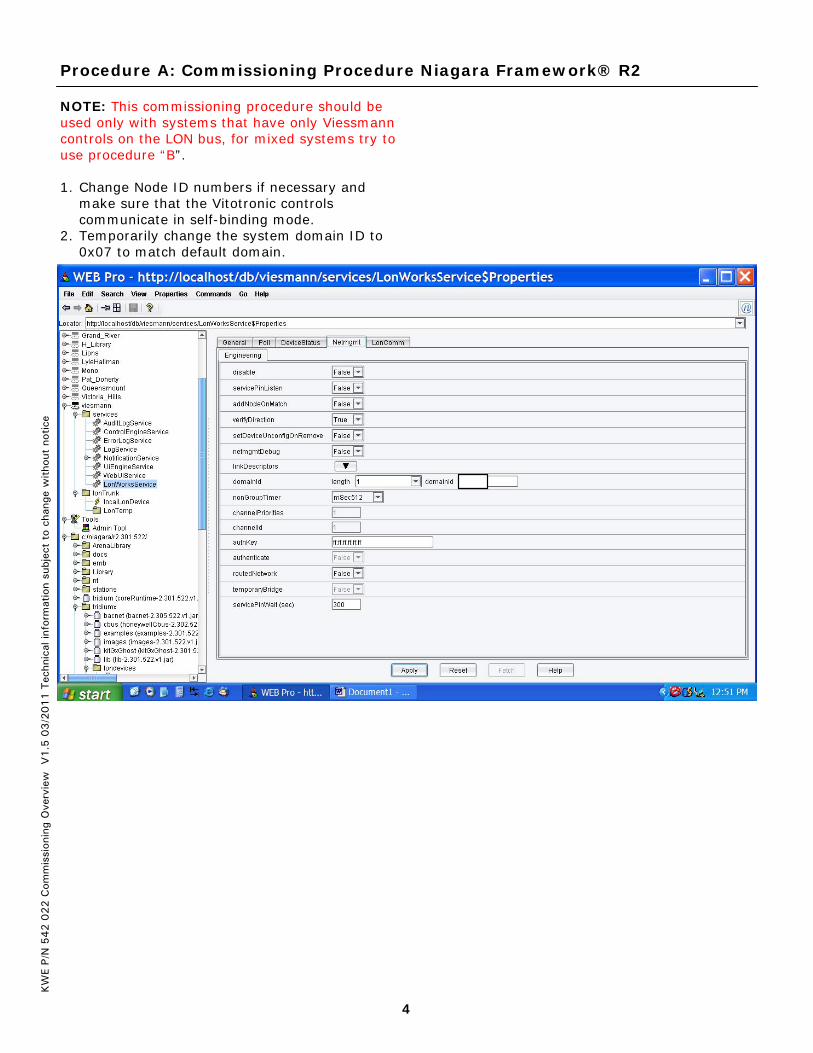
NOTE: This commissioning procedure should be used only with systems that have only Viessmann controls on the LON bus, for mixed systems try to use procedure “B”. 1. Change Node ID numbers if necessary and
make sure that the Vitotronic controls communicate in self-binding mode.
2. Temporarily change the system domain ID to 0x07 to match default domain.
Procedure A: Commissioning Procedure Niagara Framework® R2
5
KW
E P/
N 5
42 0
22 C
omm
issi
onin
g O
verv
iew
V
1.5
03/2
011 T
echn
ical
info
rmat
ion
subj
ect
to c
hang
e w
itho
ut n
otic
e
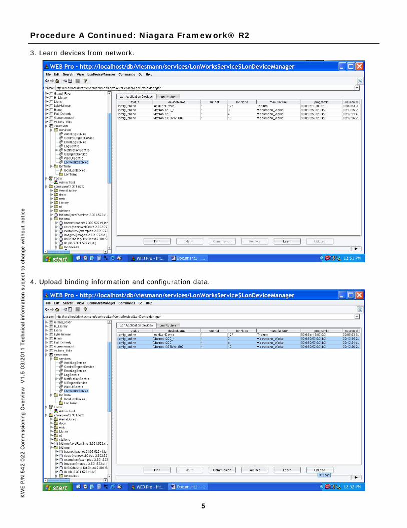
3. Learn devices from network.
4. Upload binding information and configuration data.
Procedure A Continued: Niagara Framework® R2

6
KW
E P/
N 5
42 0
22 C
omm
issi
onin
g O
verv
iew
V
1.5
03/2
011 T
echn
ical
info
rmat
ion
subj
ect
to c
hang
e w
itho
ut n
otic
e
5. Change nciNetConfig on all controls from local to external.
Procedure A Continued: Niagara Framework® R2
7
KW
E P/
N 5
42 0
22 C
omm
issi
onin
g O
verv
iew
V
1.5
03/2
011 T
echn
ical
info
rmat
ion
subj
ect
to c
hang
e w
itho
ut n
otic
e
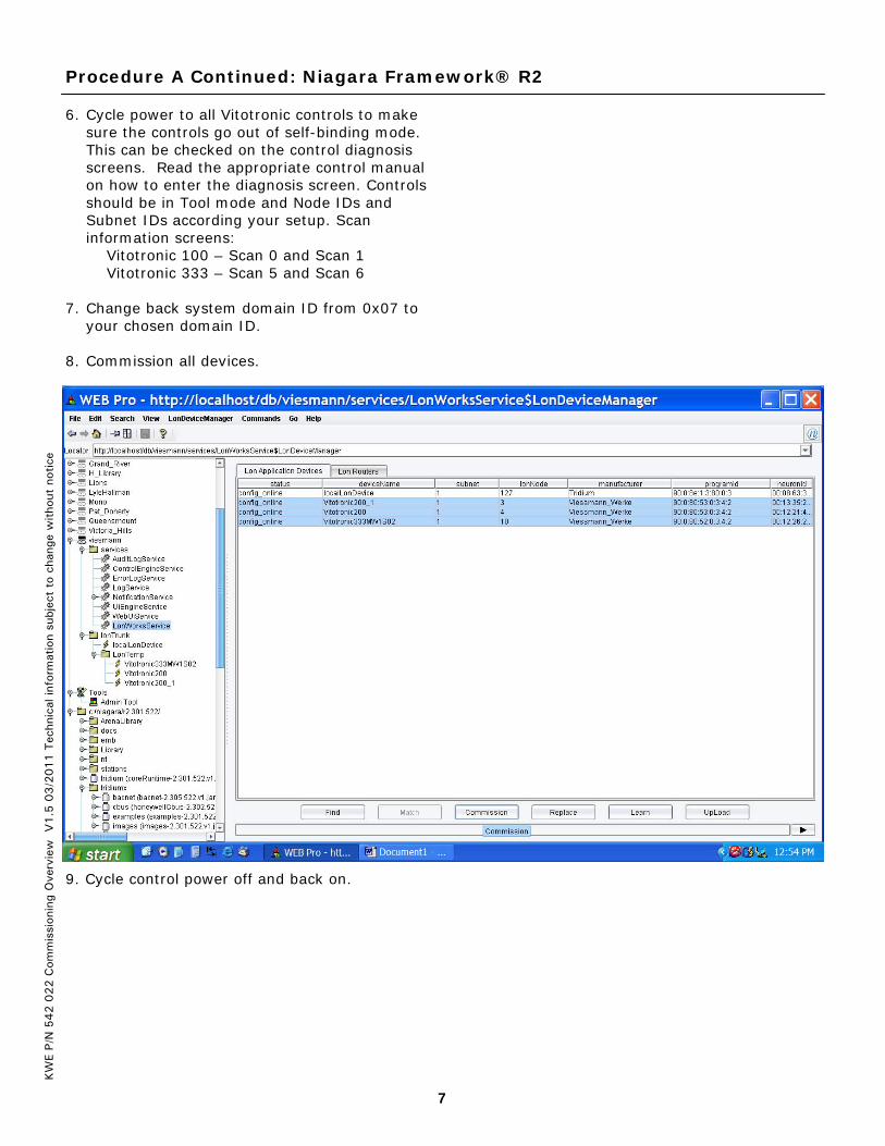
6. Cycle power to all Vitotronic controls to make sure the controls go out of self-binding mode. This can be checked on the control diagnosis screens. Read the appropriate control manual on how to enter the diagnosis screen. Controls should be in Tool mode and Node IDs and Subnet IDs according your setup. Scan information screens: Vitotronic 100 – Scan 0 and Scan 1 Vitotronic 333 – Scan 5 and Scan 6
7. Change back system domain ID from 0x07 to your chosen domain ID.
8. Commission all devices.
9. Cycle control power off and back on.
Procedure A Continued: Niagara Framework® R2

8
KW
E P/
N 5
42 0
22 C
omm
issi
onin
g O
verv
iew
V
1.5
03/2
011 T
echn
ical
info
rmat
ion
subj
ect
to c
hang
e w
itho
ut n
otic
e
10. Bind all links
11. If the control block is shown in yellow you may “Download” configurations to controller
Procedure A Continued: Niagara Framework® R2
9
KW
E P/
N 5
42 0
22 C
omm
issi
onin
g O
verv
iew
V
1.5
03/2
011 T
echn
ical
info
rmat
ion
subj
ect
to c
hang
e w
itho
ut n
otic
e
1. Change Node ID numbers if necessary and make sure that the Vitotronic controls communicate in self-binding mode.
2. Commission device using shadow objects from Tridium, use Vitotronic 200 object for Vitotronic 100/300 and Vitotronic 333 object for Vitotronic-S/C. Service pin is released by pressing “+” and “-“ together.
3. Change nciNetConfig on all controls from local to external.
4. Cycle power to all Vitotronic controls to make sure the controls go out of self-binding mode. This can be checked on the control diagnosis screens. Read the appropriate control manual on how to enter the diagnosis screen. Controls should be in Tool mode and Node IDs and Subnet IDs according to your setup. Scan information screens:
Vitotronic 100 – Scan 0 and Scan 1 Vitotronic 333 – Scan 5 and Scan 6
5. Bind the Boiler controls and cascade according to the information found in the Viessmann NR2 LON Handbook on pages 58 to 64.
Procedure B: Commissioning Procedure with Shadow Objects

10
KW
E P/
N 5
42 0
22 C
omm
issi
onin
g O
verv
iew
V
1.5
03/2
011 T
echn
ical
info
rmat
ion
subj
ect
to c
hang
e w
itho
ut n
otic
e
1. Change the Node ID numbers of all controls, if necessary, and make sure that the Vitotronic controls communicate in self-binding mode.
2. Temporarily change the system domain ID to 0x07 to match the Vitotronic’s default domain.
Procedure C: Commissioning Niagara Framework® AX

11
KW
E P/
N 5
42 0
22 C
omm
issi
onin
g O
verv
iew
V
1.5
03/2
011 T
echn
ical
info
rmat
ion
subj
ect
to c
hang
e w
itho
ut n
otic
e
3. Discover the devices and press the ADD button to move them to the database. Change the names of the controls to reflect Node IDs and boiler numbers (a Vitotronic100 may be recognized as a Vitotronic200 which is ok since they use the same LON card.)
Procedure C Continued: Commissioning Niagara Framework® AX

12
KW
E P/
N 5
42 0
22 C
omm
issi
onin
g O
verv
iew
V
1.5
03/2
011 T
echn
ical
info
rmat
ion
subj
ect
to c
hang
e w
itho
ut n
otic
e
4. Highlight all controls, then commission them. NOTE: The controls are still not part of the BMS system!
5. Highlight all controls and click on “Quick Learn” to learn the existing links created in self-binding mode. NOTE: Looking at Links Manager will show no links until “Quick Learn” process is completed.
Procedure C Continued: Commissioning Niagara Framework® AX

13
KW
E P/
N 5
42 0
22 C
omm
issi
onin
g O
verv
iew
V
1.5
03/2
011 T
echn
ical
info
rmat
ion
subj
ect
to c
hang
e w
itho
ut n
otic
e
Procedure C Continued: Commissioning Niagara Framework® AX
6. Check whether the connections were learned using “Lon Link Manager”
You can also check the LonNetwork Wire Sheet to see the connections

14
KW
E P/
N 5
42 0
22 C
omm
issi
onin
g O
verv
iew
V
1.5
03/2
011 T
echn
ical
info
rmat
ion
subj
ect
to c
hang
e w
itho
ut n
otic
e
Procedure C Continued: Commissioning Niagara Framework® AX
7. Under the “Property Sheet” of each control; change nciNetConfig from local to external. Important Note: Even if nciNetConfig is already showing “Cfg External” re-select “Cfg External” and hit save. (Right click -> Force read to verify).
Final Steps Cycle power to all the Vitotronic controls to make sure the controls go out of self-binding mode. This can be verified by looking at the scan codes on the control. Read the appropriate control manual on how to enter the diagnostics screen. Controls should be in Tool mode and Node IDs and Subnet IDs should be set according to your setup. Scan information screens: Vitotronic 100 – Scan 0 and Scan 1 Vitotronic 333 – Scan 5 and Scan 6 After communication is successfully established and verified, you can change the control domain ID to the intended system Domain ID (Step 2.). NOTE: As soon as the control Domain ID is changed, communication will be interrupted until re-commissioning is completed. If a change of Domain ID is made, you will need to re-commission all Vitotronic controls (Step 4). After re-commissioning, cycle the power on each control in order to re-establish communications. The complete integration of the controls should finish off with clicking on the Bind button for all of the Viessmann controls.

15
KW
E P/
N 5
42 0
22 C
omm
issi
onin
g O
verv
iew
V
1.5
03/2
011 T
echn
ical
info
rmat
ion
subj
ect
to c
hang
e w
itho
ut n
otic
e
Notes

KW
E P/
N 5
42 0
22 C
omm
issi
onin
g O
verv
iew
V
1.5
03/2
011 T
echn
ical
info
rmat
ion
subj
ect
to c
hang
e w
itho
ut n
otic
e
KWE Technologies Group 750 McMurray Road Waterloo, Ontario, Canada N2V 2G5 Tel: (519) 747-5042 Fax: (519) 747-4448 www.kwe-tech.com [email protected]