USE OF TRAVELLING WAVES PRINCIPLE IN PROTECTION …
52
USE OF TRAVELLING WAVES PRINCIPLE IN PROTECTION SYSTEMS AND RELATED AUTOMATIONS Publication: April 2021
Transcript of USE OF TRAVELLING WAVES PRINCIPLE IN PROTECTION …

USE OF TRAVELLING WAVES PRINCIPLE IN PROTECTION
SYSTEMS AND RELATED AUTOMATIONS
Publication: April 2021

USE OF TRAVELLING WAVES PRINCIPLE IN PROTECTION SYSTEM AND RELATED AUTOMATIONS
ENTSO-E | Rue de Spa, 8 | 1000 Brussels | [email protected] | www.entsoe.eu | @entso_e Page 2 of 52
TABLE OF CONTENTS DEFINITIONS .............................................................................................................................................. 3
EXECUTIVE SUMMARY ................................................................................................................................ 4
LIST OF FIGURES ......................................................................................................................................... 6
1 INTRODUCTION ....................................................................................................................... 7
2 TRAVELING WAVES .................................................................................................................. 8
3 MODERN DEVICE BASED TRAVELLING WAVE ............................................................................17
4 DRIVING FACTORS ABOUT USE TRAVELLING WAVES DEVICE .....................................................24
5 CHALLENGES AND/OR LIMITATIONS OF USE ............................................................................28
6 EXPERIENCE OF APPLICATION TW DEVICE ................................................................................32
7 TSO’S QUESTIONNAIRE ...........................................................................................................36
8 CONCLUSION ..........................................................................................................................51
9 REFERENCES ...........................................................................................................................52
(Veganzones, 2018) (Joint Working Group: Reigh Walling, 2015) (SIEMENS Power Academy, 2014) (Schneider Electric, 2016) (Roberts,
Guzmán, & Schweitzer III, 1993) (Johan Morren, 2007) (] Zheng-rong Wu, 2011) (Mario Ndreko, 2016)

USE OF TRAVELLING WAVES PRINCIPLE IN PROTECTION SYSTEM AND RELATED AUTOMATIONS
ENTSO-E | Rue de Spa, 8 | 1000 Brussels | [email protected] | www.entsoe.eu | @entso_e Page 3 of 52
DEFINITIONS
Travelling Wave (TW): An electromagnetic wave propagating in a transmission line
characterized by sinusoidal field component that decrease exponentially in magnitude due to
losses, as a function of distance in the direction of propagation, and with a linear variation of
phase.
Travelling Wave Fault Location (TWFL): Method or algorithm identifying the location of the
fault through the analysis of travelling waves
Time – Domaine Protection: Protection relays that use time analysis algorithms between the
prefault network and the faulty network (Incremental Quantities)
Power Electronics Based Generation (PEBG): Generation that is connected to the network
through power electronic converters. I.E. Wind Farms, Photovoltaic Plants, etc.
SMV (Sampled Measured Values): Sampled Values (SV) are used for transmitting digitalized
instantaneous values of power system measures, mainly primary currents and voltages. In that
way SVs can easily replace the use of analogical secondary measures. SVs are published in the
substation network and are able to be subscribed by any device configured to use it.
IEC 61850 Protocol: An international communication protocol used for smart electronic devices
at electrical substations. These protocols run over TCP/IP networks or substation LANs using
high speed switched Ethernet to obtain response times below four milliseconds, necessary for
protective relaying. Current standard mappings are MMS (Manufacturing Message
Specification), GOOSE (Generic Object Oriented Substation Event) and SMV (Sampled Measured
Values).
IED: Intelligent Electronic Device
HVDC: High voltage DC connection link
OHL: overhead transmission Line
CT: Current Transformer
VT: Voltage Transformer
VTC: Voltage Capacitive Transformer

USE OF TRAVELLING WAVES PRINCIPLE IN PROTECTION SYSTEM AND RELATED AUTOMATIONS
ENTSO-E | Rue de Spa, 8 | 1000 Brussels | [email protected] | www.entsoe.eu | @entso_e Page 4 of 52
EXECUTIVE SUMMARY
The purpose of this report is to share operational experiences and knowledge of new protection
equipment which does not use traditional voltage and current phasors. The report provides a
general overview of the current state of the art of Travelling Wave (TW) based devices and their
applications.
These devices use the frequency and linear variation of phase of the relative traveling waves
generated by electrical faults to detect, localize and initiate the necessary actions for a rapid
elimination of the fault.
This report initially describes the travelling wave fundamental principles and how these
concepts are introduced and used in implementing new functions in modern digital protection
and control equipment. The report focuses on their interaction with new ways of
communications (Fiber Optics, TCP/IP networks, etc.) and on their application in HVDC
connections.
The report further considers the costs and benefits related to the use of Travelling-Wave based
devices, the problems with the use of traditional CTs and VTs and the need for time
synchronization.
The impacts of new devices on commissioning and maintenance programmes once integrated
into protection and control systems are also discussed.
A questionnaire had been created by the ENTSO-E Protection Equipment subgroup’s (SG)
members and distributed, to the TSOs involved in the SG, in order to gather information about
the state of Travelling Wave devices/system penetration in their transmission grids and about
the impact on the currently implemented protection systems. The analysis of the questionnaire
concludes that the use of these systems is not very widespread, and that their main purpose is
for fault location.
TSOs prefer relevant operational experience, supporting analyses, and integration in systems
with electromechanical or digital technology before undertaking projects to provide for the
standardisation of these applications.
A few Travelling Wave fault localisation systems which are currently in operation are presented
which have proved their worth both in terms of accuracy and correct fault selection.
From the analysis, it is also found that Travelling Wave devices are mainly used in autonomous
systems not integrated in the station protection and control systems as TSOs wait for large-
scale integration into standard Intelligent Electronic Devices (IED).

USE OF TRAVELLING WAVES PRINCIPLE IN PROTECTION SYSTEM AND RELATED AUTOMATIONS
ENTSO-E | Rue de Spa, 8 | 1000 Brussels | [email protected] | www.entsoe.eu | @entso_e Page 5 of 52
The report also concludes that systems using TW devices have
extremely high-performance and reliability, but their diffusion is still strongly limited by the
scarce supply on the market, especially by the large European manufacturers.
It is expected, however, that in the short term all the major manufacturers will introduce more
IEDs equipped with TW functions in order to meet resiliency requirements and to assist future
applications in new grid scenarios (extreme weather events, decarbonisation and transition
from large conventional generation to small distributed generation, etc.).

USE OF TRAVELLING WAVES PRINCIPLE IN PROTECTION SYSTEM AND RELATED AUTOMATIONS
ENTSO-E | Rue de Spa, 8 | 1000 Brussels | [email protected] | www.entsoe.eu | @entso_e Page 6 of 52
LIST OF FIGURES
FIGURE 1: EQUIVALENT CIRCUIT OF A SEGMENT OF A TWO-CONDUCTOR TRANSMISSION LINE.[2] ........................ 9
FIGURE 2: ILLUSTRATION OF THE INCIDENT (II), TRANSMITTED (IT), AND REFLECTED (IR) WAVES [2] ................... 12
FIGURE 3 : OPERATIONAL PRINCIPLE OF A TRAVELLING WAVE RELAY [3] ............................................................... 17
FIGURE 4: OPERATIONAL PRINCIPLE OF THE SINGLE ENDED TRAVELLING WAVE FAULT LOCATOR METHOD [3] ... 19
FIGURE 5: APPLICATION ON-LINE TIME DOMAIN PROTECTION [4] .......................................................................... 20
FIGURE 6: VOLTAGE AND CURRENT TWS FOR A FORWARD (A) AND REVERSE (B) FAULT.[4] .................................. 21
FIGURE 7: CURRENT TW TIMING AND POLARITIES FOR EXTERNAL (A) AND INTERNAL (B) FAULTS[4] .................... 23
FIGURE 8: EXAMPLE OF AN INPUT SIGNAL PROCESSING [6]..................................................................................... 29
FIGURE 9: TERNA HV OHL 071 ................................................................................................................................... 33
FIGURE 10: COMUNICATION SYSTEM FROM TERMINAL DETECTION UNIT‘ AND CENTRAL ACQUISITION SERVER . 33
FIGURE 11: PRINT SCREEN ON TW FAULT LOCALIZZATION DATA ............................................................................ 34
FIGURE 12: TOWER FAULT SITE ................................................................................................................................. 35
FIGURE 13: DISTRIBUTION ANSWERS TO Q1.1 ......................................................................................................... 37
FIGURE 14: DISTRIBUTION ANSWERS TO Q1.2 ......................................................................................................... 38
FIGURE 15: DISTRIBUTION ANSWERS TO Q1.3 ......................................................................................................... 38
FIGURE 16: DISTRIBUTION ANSWERS TO Q1.4 ......................................................................................................... 39
FIGURE 17: DISTRIBUTION ANSWERS TO Q1.5 ......................................................................................................... 40
FIGURE 18: DISTRIBUTION ANSWERS TO Q1.6 ......................................................................................................... 40
FIGURE 19:DISTRIBUTION ANSWERS TO Q2.1 .......................................................................................................... 41
FIGURE 20: DISTRIBUTION ANSWERS TO Q2.2 ......................................................................................................... 42
FIGURE 21: DISTRIBUTION ANSWERS TO Q2.3 ......................................................................................................... 43
FIGURE 22: DISTRIBUTION ANSWERS TO Q2.4 ......................................................................................................... 44
FIGURE 23: DISTRIBUTION ANSWERS TO Q2.5 ......................................................................................................... 44
FIGURE 24: DISTRIBUTION ANSWERS TO Q3.1 ......................................................................................................... 45
FIGURE 25: DISTRIBUTION ANSWERS TO Q3.2 ......................................................................................................... 46
FIGURE 26: DISTRIBUTION ANSWERS TO Q3.3 ......................................................................................................... 46
FIGURE 27: DISTRIBUTION ANSWERS TO Q3.4 ......................................................................................................... 47
FIGURE 28: DISTRIBUTION ANSWERS TO Q3.6 ......................................................................................................... 48
FIGURE 29: DISTRIBUTION ANSWERS TO Q3.7 ......................................................................................................... 48
FIGURE 30: DISTRIBUTION ANSWERS TO Q3.8 ......................................................................................................... 49
FIGURE 31: DISTRIBUTION ANSWERS TO Q3.9 ......................................................................................................... 50
1 INTRODUCTION
The evolution of transmission networks is characterized by the wide spread of distributed
power electronic base generation (PEBG), increase of HVDC interconnections and a high use
of mixed aerial/cable lines. Consequently, a reduction of the short circuit power in the nodes
of the network and an overall reduction in system inertia is observed. Additionally, with
requirements to ensure high standards of reliability and reduced asset out of service times
there is a need to analyse the use of new technologies in the field of protection systems.
The focus of protection systems is to improve fast fault detection and to optimize, both
organizationally and economically, the operation needed for restoration.
The use of systems that can analyse the electromagnetic disturbance generated by the fault
(Travelling Wave) can highly increase the performance and selectivity of protection relays,
highlighting that the classical approach based on phasor algorithms (voltage and/or current)
which may no longer be appropriate (Phasor Limitation) for the new challenging scenario of
the transmission networks.
.

USE OF TRAVELLING WAVES PRINCIPLE IN PROTECTION SYSTEM AND RELATED AUTOMATIONS
ENTSO-E | Rue de Spa, 8 | 1000 Brussels | [email protected] | www.entsoe.eu | @entso_e Page 8 of 52
2 TRAVELING WAVES
When a fault occurs on the transmission lines the abrupt voltage variation and current causes
a high-frequency electromagnetic pulse called "Traveling wave" (TW). These waves travel on
the lines, propagating from the point of failure to the opposite ends of the line, at a near speed
to that of the light. It is therefore a transitory phenomenon of very short duration, in the order
of microseconds or at most milliseconds, in which the useful energy is present at frequencies
between 2kHz and 10MHz [1].
Since 1950 Crossley and McLaren were pioneers of proposing the phenomenon of traveling
waves for fault location estimation in power systems protections. They focused on the point
that when a fault happens, traveling waves were generated at the fault point. These traveling
waves propagated from the fault point towards the terminals and returned. The time required
for propagation and returning is an important hypothesis for estimation of the location of
fault. However, some difficulties have been found on precise definition of fault location in
transmission lines, based on the estimation of propagation time of traveling waves, because
of the variation of the propagation distance.
Difficulties such as the measurement of arrival time, detection of first traveling wave for
correlation, identification of fault near terminals because of less noticeable variation in
traveling wave, make these methods less applicable to extensive and highly interconnected
grids. Furthermore, problems correlated to a probabilistic approach and the existence of bias
have not allowed extensive application of these devices.
Moreover, these techniques are mature for the high voltage alternating current (HVAC)
transmission system where polarity of alternating current (AC) is varied in each cycle but are
not so easily transferrable in the HVDC transmission system because of different
characteristics of DC faults.
In the late 1960s TW techniques were gradually abandoned due to poor reliability and
maintenance problems which can be summarized as:
— The TWs were measured by detecting bus voltage;
— Specially designed voltage coupler was used;
— High speed data acquisition technology was not available;
— Absence of accurate time synchronization and effective data communication
techniques.
USE OF TRAVELLING WAVES PRINCIPLE IN PROTECTION SYSTEM AND RELATED AUTOMATIONS
ENTSO-E | Rue de Spa, 8 | 1000 Brussels | [email protected] | www.entsoe.eu | @entso_e Page 9 of 52
Traveling Wave Principles
To understand the relationship between failures it is necessary to know the theory of
electromagnetic waves and modelling of the transmission lines from an electromagnetic point
of view.
Power system faults result from the unintended breakdown of insulation. At the very first
instant of the fault, the current is only supplied locally from the charge stored in the line
capacitance. At this instant, a remote observer performing measurements at the line terminal
(substation) has no way of knowing that the fault has occurred. The first information about
the fault reaches the observer when TW, which propagates very close to the speed of light,
travels down the line till the observer position. The TWs reach the line terminals and then are
transmitted and reflected depending on the relative values of the characteristic impedances
of the line and the adjacent network components.
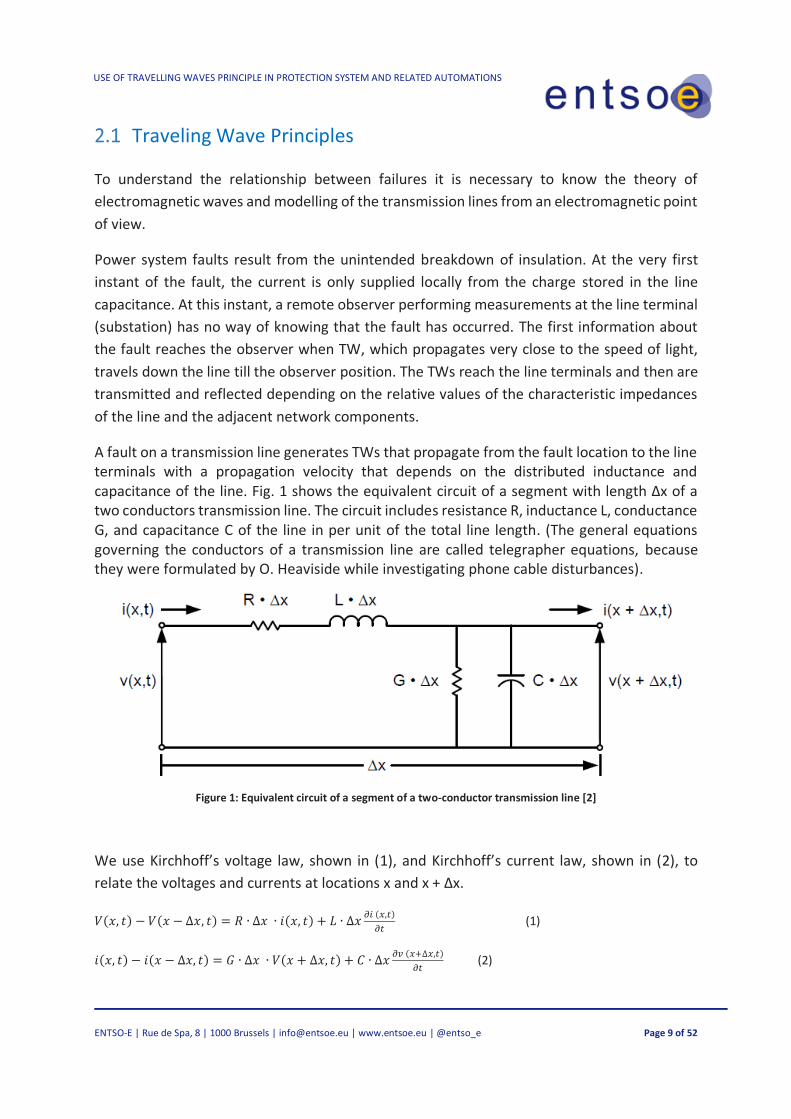
A fault on a transmission line generates TWs that propagate from the fault location to the line terminals with a propagation velocity that depends on the distributed inductance and capacitance of the line. Fig. 1 shows the equivalent circuit of a segment with length Δx of a two conductors transmission line. The circuit includes resistance R, inductance L, conductance G, and capacitance C of the line in per unit of the total line length. (The general equations governing the conductors of a transmission line are called telegrapher equations, because they were formulated by O. Heaviside while investigating phone cable disturbances).
Figure 1: Equivalent circuit of a segment of a two-conductor transmission line [2]
We use Kirchhoff’s voltage law, shown in (1), and Kirchhoff’s current law, shown in (2), to
relate the voltages and currents at locations x and x + Δx.
𝑉(𝑥, 𝑡) − 𝑉(𝑥 − ∆𝑥, 𝑡) = 𝑅 ∙ ∆𝑥 ∙ 𝑖(𝑥, 𝑡) + 𝐿 ∙ ∆𝑥𝜕𝑖 (𝑥,𝑡)
𝜕𝑡 (1)
𝑖(𝑥, 𝑡) − 𝑖(𝑥 − ∆𝑥, 𝑡) = 𝐺 ∙ ∆𝑥 ∙ 𝑉(𝑥 + ∆𝑥, 𝑡) + 𝐶 ∙ ∆𝑥𝜕𝑣 (𝑥+∆𝑥,𝑡)
𝜕𝑡 (2)

USE OF TRAVELLING WAVES PRINCIPLE IN PROTECTION SYSTEM AND RELATED AUTOMATIONS
ENTSO-E | Rue de Spa, 8 | 1000 Brussels | [email protected] | www.entsoe.eu | @entso_e Page 10 of 52
We can divide both sides of (1) and (2) by the line segment length Δx to obtain the rate of
change of the voltage and current for a change in location Δx. If we assume the change in
location Δx approaches zero, we will obtain derivatives of the voltage and current with respect
to the position x as shown in (3) and (4). These equations determine the voltage and current
as a function of location (x) and time (t) for the two-conductor transmission line. The negative
signs indicate that the amplitudes of the waves decrease as x increases.
𝜕𝑉(𝑥,𝑡)
𝜕𝑥= −𝑅 ∙ 𝑖(𝑥, 𝑡) − 𝐿
𝜕𝑖(𝑥,𝑡)
𝜕𝑡 (3)
𝜕𝑖(𝑥,𝑡)
𝜕𝑥= −𝐺 ∙ 𝑣(𝑥, 𝑡) − 𝐶
𝜕𝑉(𝑥,𝑡)
𝜕𝑡 (4)
We substitute the Heaviside operator 𝑆 =𝜕
𝜕𝑡
in (3) and (4) to transform these equations from the time domain into the Laplace domain as
shown in (5) and (6)
𝜕𝑉(𝑥,𝑠)
𝜕𝑥= −(𝑅 + 𝑠𝐿) ∙ 𝑖(𝑥, 𝑠) (5)
𝜕𝑖(𝑥,𝑠)
𝜕𝑥= −(𝐺 + 𝑠𝐶) ∙ 𝑉(𝑥, 𝑠) (6)
We further introduce Z = R + sL and Y = G + sC and use them to obtain (7) and (8).
𝜕𝑉(𝑥,𝑠)
𝜕𝑥= −𝑍 ∙ 𝑖(𝑥, 𝑠) (7)
𝜕𝑖(𝑥,𝑠)
𝜕𝑥= −𝑌 ∙ 𝑉(𝑥, 𝑠) (8)
Our goal is to have two separate equations that would involve only the voltage and only the
current, but not both. We can accomplish this if we take the derivative of (7) and (8) with
respect to x to obtain (9) and (10).
𝜕𝑉2(𝑥,𝑠)
𝜕𝑥2 = −𝑍 ∙𝜕𝑖(𝑥,𝑠)
𝜕𝑥 (9)
𝜕𝑖2(𝑥,𝑠)
𝜕𝑥2 = −𝑌 ∙𝜕𝑉(𝑥,𝑠)
𝜕𝑥 (10)
We then substitute (7) and (8) into (9) and (10) to obtain the voltage and current wave
equations (11) and (12).
𝜕𝑣2(𝑥,𝑠)
𝜕𝑥2 = −𝑍 ∙ 𝑌 ∙ 𝑉(𝑥, 𝑠) (11)
𝜕𝑖2(𝑥,𝑠)
𝜕𝑥2 = −𝑌 ∙ 𝑍 ∙ 𝑖(𝑥, 𝑠) (12)
Equation (13) defines the propagation constant γ, and (14) and (15) are the wave equations
that include γ.
𝛾 = √𝑍 ∙ 𝑌 (13)
𝜕𝑣2(𝑥,𝑠)
𝜕𝑥2 = 𝛾2 ∙ 𝑉(𝑥, 𝑠) (14)

USE OF TRAVELLING WAVES PRINCIPLE IN PROTECTION SYSTEM AND RELATED AUTOMATIONS
ENTSO-E | Rue de Spa, 8 | 1000 Brussels | [email protected] | www.entsoe.eu | @entso_e Page 11 of 52
𝜕𝑖2(𝑥,𝑠)
𝜕𝑥2 = 𝛾2 ∙ 𝑖(𝑥, 𝑠) (15)
Equations (14) and (15) describe the TWs in the Laplace domain. Solving these equations
requires assuming a disturbance, such as a step change in voltage caused by a fault, and a set
of boundary conditions, such as an open line terminal (current is zero) or a transition point to
a bus. Before we can discuss any specific TWs, let us look at the general solutions of the TW
equations, irrespective of the boundary conditions.
Equations (16) and (17) are the general solutions for the second-order partial differential
equations (14) and (15). The voltage and current are the sum of two components; these
components are referred to as the incident (I) wave 𝑉𝐼𝑒−𝛾𝑥; 𝐼𝐼𝑒−𝛾𝑥 and the reflected (R)
wave 𝑉𝑅𝑒−𝛾𝑥, 𝐼𝑅𝑒−𝛾𝑥
𝑉(𝑥, 𝑡) = 𝑉𝐼𝑒−𝛾𝑥 + 𝑉𝑅𝑒−𝛾𝑥 (16)
𝑖(𝑥, 𝑡) = 𝑖𝐼𝑒−𝛾𝑥 + 𝑖𝑅𝑒−𝛾𝑥 (17)
When we look at voltage and current from a given point on the transmission line, we can
calculate the ratio between the voltage and current for the incident and the reflected
components, respectively; these ratios depend on the line parameters and define the line
characteristic impedance as shown in (18) and (19).
𝑍𝐶 =𝑉𝐼
𝑖𝐼= √
𝑍
𝑌 (18)
𝑍𝐶 =𝑉𝑅
𝑖𝑅= √
𝑍
𝑌 (19)
Equation (23) expresses i(x,t) as a function of VI, VR, and ZC.
𝒊(𝒙, 𝒕) =𝟏
𝒁𝒄(𝑽𝑰𝒆−𝜸𝒙 − 𝑽𝑹𝒆𝜸𝒙) (20)
So far, we have seen how the travelling wave propagates on the line in free space. Now let us
examine what happens when a TW reaches a discontinuity, i.e., a point when the
characteristic impedance of the circuit changes voltage and a current component, related by
the characteristic impedance of the line (18) and (19). When an incident TW with current (i I)
and voltage (vI) reaches a line terminal, a portion of the incident TW is transmitted, (iT) and
(vT), and the remaining portion is reflected, (iR) and (vR). The amount of energy that is
transmitted and reflected depends on the characteristic impedance beyond the transition
point (ZT) and the characteristic impedance (ZC) of the line the wave travelled, as shown in Fig.
2. A device at the line terminal measures current and voltage values that are the sum of the
incident and reflected TWs.

USE OF TRAVELLING WAVES PRINCIPLE IN PROTECTION SYSTEM AND RELATED AUTOMATIONS
ENTSO-E | Rue de Spa, 8 | 1000 Brussels | [email protected] | www.entsoe.eu | @entso_e Page 12 of 52
Figure 2: Illustration of the incident (iI), transmitted (iT), and reflected (iR) waves [2]
When a surge reaches termination impedance (ZT) at the terminal, the voltage (v) at the
terminal equals iZT. The arrival of iI and vI at the terminal creates reflected TWs (iR) and (vR)
according to (21).
𝑉
𝐼=
𝑉𝐼+𝑉𝑅
𝑖𝐼+𝑖𝑅= 𝑍𝑇 (21)
Our objective is to define a relationship between the incident and reflected TWs. Therefore,
we substitute (18) and (19) into (21), and we obtain (21), which is the reflected TW voltage as
a function of vI, ZC, and ZT.
𝑉𝑅 =𝑍𝑇−𝑍𝐶
𝑍𝑇+𝑍𝐶∙ 𝑉𝐼 = 𝝆𝑽 𝑽𝑰
where 𝜌𝑉 is the voltage reflection coefficient (22)
Similarly, we can obtain the current reflection coefficient 𝝆𝑰 expressed in (23).
𝝆𝑰 =𝒁𝑪−𝒁𝑻
𝒁𝑻+𝒁𝑪 (23)
Equations (22) and (23) tell us how the TW energy in the voltage and in the current divides
between the incident and reflected TWs. For example:
— If ZC = ZT, no energy is reflected and all energy is transmitted.
— If ZT = 0, the reflected TW voltage equals the incident TW voltage (with the opposite sign)
and no energy is transmitted.
— If ZT = ∞, the reflected TW current equals the incident TW current (with the opposite sign)
and no energy is transmitted.
Normally, we can separate the incident and reflected TWs when measuring both current and
voltage at the line terminal.
A fault or a lightning strike generates a surge in voltage and current. The associated TWs
attenuate as they propagate along the line because of losses caused by the line resistance and
conductance.

USE OF TRAVELLING WAVES PRINCIPLE IN PROTECTION SYSTEM AND RELATED AUTOMATIONS
ENTSO-E | Rue de Spa, 8 | 1000 Brussels | [email protected] | www.entsoe.eu | @entso_e Page 13 of 52
To analyse the propagation of TWs in systems with transmission lines having multiple
conductors, we perform modal analysis to decouple the wave propagation modes.
In modal analysis, the phase signals are linear combinations of the mode signals, and vice
versa.
These linear combinations are expressed by the following transformation matrices:
IPhase=Ti IMode (24)
VPhase=TV VMode (25)
𝐼𝑀𝑜𝑑𝑒 = 𝑇𝐼−1 𝐼𝑃ℎ𝑎𝑠𝑒 (26)
𝑉𝑀𝑜𝑑𝑒 = 𝑇𝑉−1 𝑉𝑃ℎ𝑎𝑠𝑒 (27)
In the analysis of a multiconductor line, the R, L, G, and C parameters of the transmission line
are matrices with dimensions according to the number of conductors (n). The same applies to
Z, Y, and ϒ values in the TW line model (14) and (15). Consider the propagation matrices Av in
(28) and Ai in (29), where Z and Y are the impedance and admittance matrices of the line.
Av=ZY (28)
Ai=YZ (29)
Goal is to establish how the TWs would propagate once they occur. This is normally done using
eigenvalue analysis. We will ideally select the transformation matrices Ti and Tv so that the
following matrix (ʌ) is diagonal, meaning the modes are decoupled.
⋀ = 𝑇𝑉−1 𝐴𝑉 𝑇𝑉 (30)
⋀ = 𝑇𝐼−1 𝐴𝐼 𝑇𝐼 (31)
⋀ = (𝜆1 ⋯ 0⋮ ⋱ ⋮0 ⋯ 𝜆𝑛
) (32)
The square root of each eigenvalue (m) in (32) represents the wave propagation constant
(m) for the corresponding mode m.
𝛾𝑚 = √𝜆𝑚 (33)
The real part (m) in (32) represents the attenuation constant, and the imaginary part (m)
represents the phase constant of the propagation constant (m).
USE OF TRAVELLING WAVES PRINCIPLE IN PROTECTION SYSTEM AND RELATED AUTOMATIONS
ENTSO-E | Rue de Spa, 8 | 1000 Brussels | [email protected] | www.entsoe.eu | @entso_e Page 14 of 52
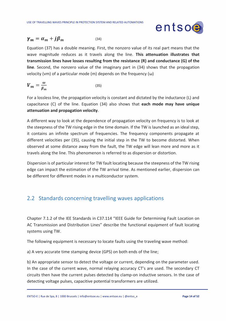
𝜸𝒎 = 𝜶𝒎 + 𝒋𝜷𝒎 (34)
Equation (37) has a double meaning. First, the nonzero value of its real part means that the
wave magnitude reduces as it travels along the line. This attenuation illustrates that
transmission lines have losses resulting from the resistance (R) and conductance (G) of the
line. Second, the nonzero value of the imaginary part in (34) shows that the propagation
velocity (vm) of a particular mode (m) depends on the frequency (ω)
𝑽𝒎 =𝝎
𝜷𝒎 (35)
For a lossless line, the propagation velocity is constant and dictated by the inductance (L) and
capacitance (C) of the line. Equation (34) also shows that each mode may have unique
attenuation and propagation velocity.
A different way to look at the dependence of propagation velocity on frequency is to look at
the steepness of the TW rising edge in the time domain. If the TW is launched as an ideal step,
it contains an infinite spectrum of frequencies. The frequency components propagate at
different velocities per (35), causing the initial step in the TW to become distorted. When
observed at some distance away from the fault, the TW edge will lean more and more as it
travels along the line. This phenomenon is referred to as dispersion or distortion.
Dispersion is of particular interest for TW fault locating because the steepness of the TW rising
edge can impact the estimation of the TW arrival time. As mentioned earlier, dispersion can
be different for different modes in a multiconductor system.
Standards concerning travelling waves applications
Chapter 7.1.2 of the IEE Standards in C37.114 “IEEE Guide for Determining Fault Location on
AC Transmission and Distribution Lines” describe the functional equipment of fault locating
systems using TW.
The following equipment is necessary to locate faults using the traveling wave method:
a) A very accurate time stamping device (GPS) on both ends of the line;
b) An appropriate sensor to detect the voltage or current, depending on the parameter used.
In the case of the current wave, normal relaying accuracy CT’s are used. The secondary CT
circuits then have the current pulses detected by clamp-on inductive sensors. In the case of
detecting voltage pulses, capacitive potential transformers are utilized.

USE OF TRAVELLING WAVES PRINCIPLE IN PROTECTION SYSTEM AND RELATED AUTOMATIONS
ENTSO-E | Rue de Spa, 8 | 1000 Brussels | [email protected] | www.entsoe.eu | @entso_e Page 15 of 52
As per chapter 7.2, the accuracy limitations are described below:
a) Assumptions made in determining fault location: 1. The traveling waveform travels at the speed of light (velocity of propagation equals 3
× 108 m/sec);
2. Discontinuities in the electrical system produce wave reflections. Each discontinuity
can be used as calibration for the timing of the wave arrival at the receiving end of the
line. Since the velocity of propagation is constant, the distance can be calculated quite
accurately;
3. A communications circuit is required to transmit the time stamped data back to a
central location;
4. A computer capable of retrieving the remote data, distinguishing the appropriate
waveform for the fault location calculation, and providing the appropriate calculations
to the fault.
b) Accuracy: 1. GPS-based traveling wave fault locating systems where timestamp information is
provided from both ends of the faulted transmission lines has proven to be very
accurate. Operating results have shown accuracy on the performance of ± 300 meters,
even for long lines;
2. Wave detection error due to interpretation of the transient is a major form of error.
This error results from many transients and/or reflected transients appearing the
same. This is especially true of lightning strikes. Lightning storms with multiple strokes
can cause major confusion in terms of which transient was associated with which fault;
3. Stronger buses tend to dampen voltage transients. The result is lower fault locating
accuracy;
4. The GPS system is the time measuring standard. Hence, any errors in this system are
reflected into the ability to accurately locate faults. The Department of Defence
intentionally builds a small amount of uncertainty into the system;
5. Current and voltage transformers provide reasonable reproduction of transients;
6. When utilizing the one-terminal form of the traveling wave method, analysis of the
waveforms must be more sophisticated. Potentially, signature analysis may be
required because the transients are more complex.

USE OF TRAVELLING WAVES PRINCIPLE IN PROTECTION SYSTEM AND RELATED AUTOMATIONS
ENTSO-E | Rue de Spa, 8 | 1000 Brussels | [email protected] | www.entsoe.eu | @entso_e Page 16 of 52
According to their mode of operation TW locators as types A, B, C, D and E where each type is
associated with one implementation or design. All are based on detection of voltage waves
rather than current waves.
— Type A (complementary): identify fault reflections in recorded travelling transients.
— Type B (OLD): Measure time difference between fault surge arrival times at the two line
terminals using a communication link.
— Type C (OLD): Radar principle.
— Type D: Measure time difference between fault surge arrival times at 2-line terminals using
two coordinated meters at line ends.
— Type E (complementary): Measure the time delay of reflection of the injected pulse by
circuit breaker reclosure.
USE OF TRAVELLING WAVES PRINCIPLE IN PROTECTION SYSTEM AND RELATED AUTOMATIONS
ENTSO-E | Rue de Spa, 8 | 1000 Brussels | [email protected] | www.entsoe.eu | @entso_e Page 17 of 52
3 MODERN DEVICE BASED TRAVELLING WAVE
This chapter describes the main functionalities adopted today in new digital intelligent
electronic devices (IEDs). These functionalities have been made possible due to the progress
of microelectronics and communication systems (Eg. wide spread of broadband networks)
which allows the exchange of data between the two end devices, in a safe, fast and high
bandwidth way.
The theory of travelling waves has also benefited greatly from the increased sampling capacity
of the devices that allow to detect, analyse, and compare the variations of the electrical
quantities (voltage and/or current) typical of TW that are in high frequency (order of hundreds
of kHz).
Fault Location function
Faults on lines cause transients that travel along power lines at speed of light in both directions
from the place of the fault. This propagation is known as travelling waves.
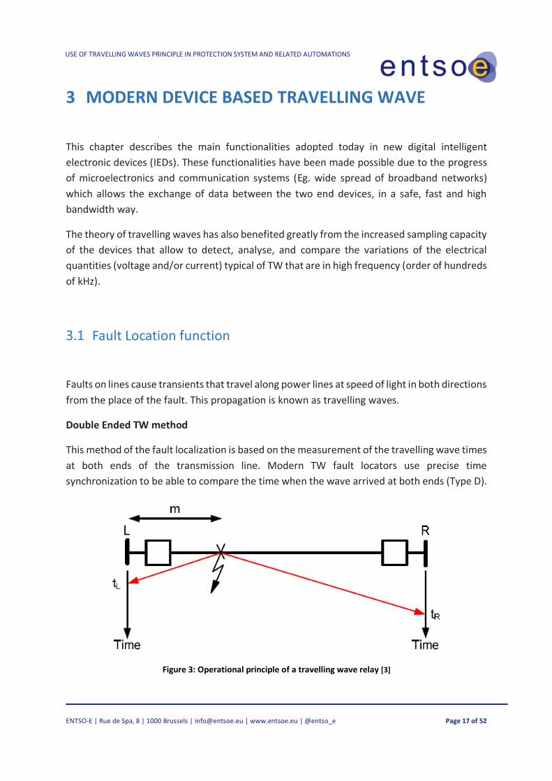
Double Ended TW method
This method of the fault localization is based on the measurement of the travelling wave times
at both ends of the transmission line. Modern TW fault locators use precise time
synchronization to be able to compare the time when the wave arrived at both ends (Type D).
Figure 3: Operational principle of a travelling wave relay [3]

USE OF TRAVELLING WAVES PRINCIPLE IN PROTECTION SYSTEM AND RELATED AUTOMATIONS
ENTSO-E | Rue de Spa, 8 | 1000 Brussels | [email protected] | www.entsoe.eu | @entso_e Page 18 of 52
Terminals of both sides of a line measures arrivals times of the wave. They both uses a
common time reference with high precision. The distance of the fault from both sides is:
𝑚 = 𝑡𝐿 ∙𝐿
𝑇𝑊𝑃𝑇 (36)
𝐿 − 𝑚 = 𝑡𝑅 ∙𝐿
𝑇𝑊𝑃𝑇 (37)
Where:
L is the line length
tL is the TW arrival time at L side
tR is the TW arrival time at R side
TWPT is the travelling wave propagation time – the time it takes for the wave to run the entire
line
From these equations, it is possible to calculate the distance of the fault:
𝑚 =𝐿
2∙ (1 +
𝑡𝐿−𝑡𝑅
𝑇𝑊𝑃𝑇) (38)
The double ended fault-locating method (38) measures current TWs. A practical
implementation of this method applies the differentiator-smoother filter to current samples
taken every microsecond. The method further incorporates a time-stamping algorithm that
uses interpolation to find the time of the peak for the output of the differentiator smoother
filter. This interpolation provides a time-stamping accuracy of approximately 0.1 μs, i.e., about
ten times better than the sampling interval. The double-ended TW-based fault-locating
method is simple, yet very accurate. It requires identifying and timestamping only the very
first TWs at both line terminals. Not having to isolate and identify the origin of any subsequent
TWs is a great advantage of this fault-locating method compared with the single-ended
method. It requires the TW-based fault-locating devices at both line terminals to be
synchronized so that the TW arrival times at both line terminals are captured with the same
time reference. The synchronization is typically achieved using satellite-synchronized clocks
or using a direct point-to-point fibre-optic channel between the devices.
The double-ended TW-based fault-locating method has a field-proven track record with
reported accuracy within one tower span (300 m) on average. When tested under ideal
conditions, the double-ended TW-based fault locating method implemented on a hardware
platform yields a 90th percentile error considerably below 20 m and a median error less than
10 m.

USE OF TRAVELLING WAVES PRINCIPLE IN PROTECTION SYSTEM AND RELATED AUTOMATIONS
ENTSO-E | Rue de Spa, 8 | 1000 Brussels | [email protected] | www.entsoe.eu | @entso_e Page 19 of 52
Single Ended TW method
This method is based on the time difference between the first arrived TW from the fault and
the first reflection from the fault measured at the local terminal. The following figure shows
how the TW reflects after a fault at F on a line of length L through the so-called Bewley
diagram in which the propagation of TWs in relation to time is represented (t0=Fault Time)
Figure 4: Operational principle of the single ended travelling wave fault locator method [3]
The travelling wave arrives from the fault to the local terminal at the time t1. Part of the wave
reflects and travels back to the fault, reflect again from the fault, and returns to the local
terminal at time t4. During the time interval t4 – t1, the TW travelled a distance of 2·m. If we
know the travelling wave propagation time, we can calculate the distance of the fault:
𝑚 =𝐿
2∙
𝑡4−𝑡1
𝑇𝑊𝑃𝑇 (39)
The main task of a TW locator based on measurement from one side is to find the TW which
is the first reflection from the fault among many of other TWs that may arrive at the local
terminal.

USE OF TRAVELLING WAVES PRINCIPLE IN PROTECTION SYSTEM AND RELATED AUTOMATIONS
ENTSO-E | Rue de Spa, 8 | 1000 Brussels | [email protected] | www.entsoe.eu | @entso_e Page 20 of 52
Protective functions related to the functions of travelling waves
Modern line protective IED now normally include incremental quantity-based high-speed
protection elements (Sub-cycle trip decision). New line IED are becoming available with both
incremental quantity- and traveling-wave-based elements. It is now a common terminology
to define these incremental quantity and traveling-wave (TW) protection operating principles
as time-domain protection principles. Normally time-domain line protective relay use a
dedicated point-to-point fiber-optic channel to provide the first-ever TW differential
protection as shown in fig. 5
Figure 5: Application on-line Time Domain Protection [4]
Traveling-Wave Elements
These elements respond to the high-frequency content (hundreds of kilohertz) in the relay
input currents and, to a lesser degree, voltages. From the signal processing point of view, TWs
can be understood as sharp changes in the input signals with the rise time in the order of a
few microseconds. The time-domain relay samples voltages and currents at the rate of 1 MHz
and extracts TWs from the raw signals using a dedicated filter. The relay may run the TW
calculations every microsecond and run the TW logic every 100 μs.
TW32 Directional Element
The TW32 directional element compares the relative polarity of the current TWs and the
voltage TWs. For a forward event, the two TWs are of opposite polarities, and for a reverse
event, they are of matching polarities. To realize the TW32 element, the time-domain relay
integrates a torque calculated from the current and voltage TWs and checks the integrated

USE OF TRAVELLING WAVES PRINCIPLE IN PROTECTION SYSTEM AND RELATED AUTOMATIONS
ENTSO-E | Rue de Spa, 8 | 1000 Brussels | [email protected] | www.entsoe.eu | @entso_e Page 21 of 52
value a few tens of microseconds into the fault (see Fig. 6). As a result, the relay responds to
the TW activity during the few tens of microseconds following the first TW. Once asserted, the
TW32 element latches for a short period of time to act as an accelerator for the dependable
TD32 directional element for permissive keying in the POTT scheme. Because of its simple
operating principle, the TW32 element does not require settings.
When applied with coupling-capacitor voltage transformers (CCVTs), the TW32 element
benefits from the parasitic capacitances across the CCVT tuning reactor and step-down
transformer [2], which otherwise block the high-frequency TW signals. These capacitances
create a path for these signal components, allowing some voltage TW signals to appear at the
secondary CCVT terminals. The element only needs accurate polarity and timing of the first
voltage TW, and therefore the element is suitable for CCVTs despite their poor reproduction
of voltage TW magnitudes, especially for the second and subsequent TWs.
Figure 6: Voltage and current TWs for a forward (a) and reverse (b) fault [4]

USE OF TRAVELLING WAVES PRINCIPLE IN PROTECTION SYSTEM AND RELATED AUTOMATIONS
ENTSO-E | Rue de Spa, 8 | 1000 Brussels | [email protected] | www.entsoe.eu | @entso_e Page 22 of 52
TW87 Differential Scheme
The TW87 scheme compares time-aligned current TWs at both ends of the protected line. For
an external fault, a TW that entered one terminal with a given polarity leaves the other
terminal with the opposite polarity exactly after TW line propagation time (see Fig. 7). To
realize the TW87 scheme, the time-domain relay extracts TWs from the local and remote
currents and identifies the first TW for each. It then searches for the exiting TW from the local
and remote currents that arrives at the opposite line terminal after the line propagation time.
The relay then calculates the operating and restraining signals from the first and exiting TWs.
The TW87 scheme uses real-time fault-location information obtained with a double-ended
fault-locating method. It also uses other proprietary security conditions [2] in addition to the
pickup and slope settings common in differential protection logic. The TW87 logic applies a
factory-selected magnitude pickup level and security slope and provides supervision threshold
settings for the user.
The supervision thresholds (TP50P and TP50G for phase and ground loops, respectively) apply
to time-domain ultrafast overcurrent elements responding to the loop incremental replica
current [2]. These thresholds confirm that the in-zone event detected using TWs is a fault and
not a switching event within the zone of protection.
The TW line propagation time (TWLPT) is a critical TW87 scheme setting. TWLPT is the one-
way TW travel time from one line terminal to the opposite terminal (see Fig. 7). This setting is
critical for TW fault locating accuracy and TW87 protection scheme security. The TW87
scheme tolerates inaccuracy in the TWLPT setting of a few microseconds. Each microsecond
of error in the TWLPT setting may result in a TW fault-locating error between 150 and 300
meters depending on whether the relay protects cables or overhead lines. So it is necessary
to measure the correct TWLPT value during the commissioning of the relay by energizing the
line with one end closed to record the reflection time of the generated TW.

USE OF TRAVELLING WAVES PRINCIPLE IN PROTECTION SYSTEM AND RELATED AUTOMATIONS
ENTSO-E | Rue de Spa, 8 | 1000 Brussels | [email protected] | www.entsoe.eu | @entso_e Page 23 of 52
Figure 7: Current TW timing and polarities for external (a) and internal (b) faults [4]

USE OF TRAVELLING WAVES PRINCIPLE IN PROTECTION SYSTEM AND RELATED AUTOMATIONS
ENTSO-E | Rue de Spa, 8 | 1000 Brussels | [email protected] | www.entsoe.eu | @entso_e Page 24 of 52
4 DRIVING FACTORS ABOUT USE TRAVELLING WAVES
DEVICE
In this chapter, the main driving factors and benefits of using this technology are presented.
Precise Fault Location
The ability to accurately determine the location of faults on power systems lines is important. It facilitates faster inspection and shorter repair times, leading to faster restoration of the faulted lines. At the same time, accurate fault location is a technical challenge because fault location estimation is done based on the limited amount of information gathered at the line terminals.
Problems which must be overcome include finite transmission line parameters accuracy, instrument measurement errors, coupling to adjacent transmission lines, unknown and often non-linear fault resistance and finite duration of faults resulting in short time window opportunity to capture necessary data.
The grid reliability and performance increase when a problem occurring in EHV transmission lines and can be located precisely, within a few hundred meters of accuracy, enabling a faster reparation or locating of the line weaknesses.
The use of Travelling Wave Fault Location is normally also dictated by its special topology, and
because the traditional impedance method is not able to give an accurate location with
multiple faults, in most of the cases the fault location from both ends are widely overlapped;
therefore these devices are often installed as a non-permanent installation just to accurately
locate the problems, mostly in case of defective isolators. Results of the equipment
performance during real faults are also analysed, showing the advantages of an accurate
supervision and its positive impact, resulting in minor costs of the maintenance activities and
identification of defective isolators derived from a precise fault localization.
Increased accuracy can lead to an exact fault location, or a closer range, which is very helpful,
reducing cost, when accessibility problems is a key factor during line check. This also translates
to a quick determination of the faulty component (usually an insulator) which, without the
correct identification, can drive to repetitive faults on the same line, degrading its availability
and, more important, also degrading the electrical hardware on the line due to electrical and
electrodynamic stress created by the fault currents. Furthermore, this has also an

USE OF TRAVELLING WAVES PRINCIPLE IN PROTECTION SYSTEM AND RELATED AUTOMATIONS
ENTSO-E | Rue de Spa, 8 | 1000 Brussels | [email protected] | www.entsoe.eu | @entso_e Page 25 of 52
environmental side effect, Eg. reducing risks of a wildfire or an oil leak in underwater cables
triggered as consequences of the failures.
When the accuracy of the fault location is trusted and reliable, the reparation time decrease
significantly, compared with traditional localization methods such as heliport or below-the-
line inspections along the entire length.
To quantify the above costs, we bring the experience of REE (Spain) related to their installation
of a TWFL System installed on 220kV line located in Lleida (north-east Spain) The following
tables show the costs incurred on line check stage, due to works to localize the origin of the
fault and unavailability of the line during this period, these days are estimated by company
experience. For the aerial line this unavailability cost is regulated by Spanish Authority and is
produced by the reduction on grid performance, when this line is out of service. This concept
is different for underwater cable, where the cost increases significantly, because the cable
unavailability is transduced to a lack of power on an affected island and needs to be supplied
by other means.
Item
Cost Traditional Locator TWFL
Days Total Days Total
Helicopter check 4 K€/day 1 4 K€ 0 0 K€
Line Unavailability 1,43 K€/day 2 2,86 K€ 1 1,43 K€
Total amount 6,86 K€ 1,43 K€
TABLE 1: Line check costs on Over Headline [5]
Item
Cost Traditional Locator TWFL
Days Total Days Total
Underwater check 25 K€/day 5 125 K€ 3 75 K€
Line Unavailability 30 K€/day 6 180 K€ 3 90 K€
Total amount 305 K€ 165 K€
TABLE 2: Line check costs on underwater cable [5]
USE OF TRAVELLING WAVES PRINCIPLE IN PROTECTION SYSTEM AND RELATED AUTOMATIONS
ENTSO-E | Rue de Spa, 8 | 1000 Brussels | [email protected] | www.entsoe.eu | @entso_e Page 26 of 52
Use of Travelling Wave Device in Hybrid Line
An interesting application for TW systems is that in lines where there are various sections
between overhead and cable, a "selective" reclosing system can be carried out. Normally, in
large interconnecting lines that have a cable section, Line Differential Protection are used in
the aerial-cable transition sections that do not perform protective functions but only signal
failure in the cable sections to cancel the self-closing of the protective system at the ends of
the entire line. Clearly, this system leads to complications both in terms of construction (need
for CT in aerial cable transitions) and costs for the additional protective system.
The adaptive location-dependent autoreclosure cancel logic based on TW can be applied to
distinguish faults on overhead line sections from faults on cable sections of hybrid lines and
to control the autorecloser accordingly directly in the Main Protection System at both ends.
Single-pole tripping and reclosing for faults can be applied on overhead sections to improve
reliability while avoiding reclosing into faults on a cable section and causing additional
damage.
Use Travelling Wave principle in Protection System
Transmission network scenarios are rapidly changing and today TSOs have to manage the
transition from traditional generation sources to renewable sources. Decarbonisation will lead
to scenarios where conventional generation in large poles will disappear in favour of
distributed generation. The loss of large generators is leading to a fast reduction of the
mechanical inertia of the system.
It is worth noting that traditional type of protection (using algorithm with phasorial voltage
and current) do not give certainty of correct intervention in a networks scenarios where the
presence of Power Electronic Based is widespread, as highlighted in the tests carried out in
the MIGRATE project (UE project to Massive Integration of Power Electronic Devices).
As we have seen in chapter 3.2, the device that use TW to elaborate protection algorithms,
are not dependent on the electrical characteristics of the installation point (SIR; Kcc etc.) nor
from the protected network portion (R;X). This can become crucial for the selective and safe
protection of portions of the network in the scenarios explained above.

USE OF TRAVELLING WAVES PRINCIPLE IN PROTECTION SYSTEM AND RELATED AUTOMATIONS
ENTSO-E | Rue de Spa, 8 | 1000 Brussels | [email protected] | www.entsoe.eu | @entso_e Page 27 of 52
An action is therefore underway by the main IED protection manufacturers to integrate these
new functions with the traditional functions so that the mix obtained will satisfy the best
overall network conditions in the short future.

USE OF TRAVELLING WAVES PRINCIPLE IN PROTECTION SYSTEM AND RELATED AUTOMATIONS
ENTSO-E | Rue de Spa, 8 | 1000 Brussels | [email protected] | www.entsoe.eu | @entso_e Page 28 of 52
5 CHALLENGES AND/OR LIMITATIONS OF USE
The fault localization based on the wave principle has not only advantages but also
disadvantages. Therefore, the protected line must be equipped with a relay using a different
fault location method as a backup protection.
Challenges related to the exact detection of TW
Faults occurring when the voltage across the fault path is small launch only small TWs.
Ultimately; faults occurring at voltage zero do not launch any TWs.
Faults very close to a line terminal launch TWs that reflect frequently and therefore overlap
with one another. In general, the principle is suitable especially for long lines. For the relay it
can be difficult to determine a fault which lies closer than approximately 3km from the
terminal.
When installing TW relays, it is necessary to consider that reflections of TWs occur not only
on the protected line, but also in the secondary circuits of current transformers.
They should have a minimum number of connections to minimize these reflections. If it is
impossible to use a dedicated CT core for the travelling wave relay it should be connected as
the first in line. In that case the first travelling wave reaching the relay, amplitude and ramp,
would not be affected by a lot of refraction points due to the change of impedance. With every
change in impedance part of the incident TW will be transmitted and part will be reflected to
the fault. The same principle applies for the secondary circuits and having more relays in the
circuit means the impedance changes with every relay in the circuit distorting the TW recorded
by the TW relay. Fortunately, these reflections, because of short cabling connections, have
high frequencies which should be filtered out by input filters in relays.
For all these cases, it is therefore particularly challenging to identify the point of evaluation of
the wave. Modern techniques for determining the time of arrival of the TW use circuits based
on smoother differentiators. Fig. 8 shows a block diagram suitable for demonstrating the
method.

USE OF TRAVELLING WAVES PRINCIPLE IN PROTECTION SYSTEM AND RELATED AUTOMATIONS
ENTSO-E | Rue de Spa, 8 | 1000 Brussels | [email protected] | www.entsoe.eu | @entso_e Page 29 of 52
Figure 8: Example of an input signal processing [6]
It is necessary to consider that even cables from the CT secondary terminals to the relay at the
end of the line adds an extra time difference that needs to be considered in the setting of the
travelling wave propagation time (TWPT).
The relay must be able to cope with lightning strikes near the protected line. Some strikes near
the line cause TW transients which normally do not cause faults, but for the relay it can look
like a fault. The difference is that during the event the voltage in the relay location does not
fall. Further the TW occurs in all three phases with the same polarity. This is an indication that
the waves were induced from the outside.
Sometimes the lightning strikes the phase wire and no flashover occurs. In this case a traveling
wave is generated and TWs with the same signature as an internal fault. In that case the TWs
at the two terminals are going to have approximately the same magnitude and the same
polarity. However, you can see one difference between this condition and a true fault
condition, which in this case relays are going to have an overvoltage condition. This method is
used to discriminate between a lightning strike that causes a flashover and one that does not.

USE OF TRAVELLING WAVES PRINCIPLE IN PROTECTION SYSTEM AND RELATED AUTOMATIONS
ENTSO-E | Rue de Spa, 8 | 1000 Brussels | [email protected] | www.entsoe.eu | @entso_e Page 30 of 52
The action of a surge arrester can also appear to the TW relay as a fault in the protected zone.
As in the case of a lightning strike to a line, the resulting waves are associated with an
overvoltage. The protection relay should be able to distinguish it from a fault.
Challenges using CT and VT protection systems
Measuring transformers are dimensioned and optimised to operate at nominal values, i.e. at 50Hz, while the transients of the travelling waves have frequencies at hundreds of kHz. Commonly used CTs have usable bands (-3dB) that arrive easily at 100KHz but often also at
200kHz or even 500kHz which can reproduce the primary signal typical of a travelling wave.
The Capacitive VT now widely used in traditional protection systems, have an operation that
is very close to low pass filters and therefore the bandwidth stops at a few tens of kHz. This is
due to the no-iron-resonance circuitry.
For this reason, many applications prefer to work with the current wave. Some manufacturers
use voltage waves, so they use CVT, exploiting the parasitic capacitance in transformers which,
working as a high-pass filter, allow the detection of the travelling wave. Other companies,
when it is considered necessary to analyse the voltage wave, use an indirect measurement.
With reference to the Std model of the VTC, the voltage wave passing through the capacitive
divider to the primary produces a current wave, which is drained to earth. On the ground cable
of the VTC, the current wave is extracted by means of a suitable current transducer.
Terminations with a high surge impedance, such as those with only a power transformer
behind the relay, prevent the relay from measuring TW currents. In some applications, TWs
can be highly distorted because of stray coupling between the primary and secondary sides of
the instrument transformers or coupling from the primary conductors to the secondary wiring.
Challenges with communication channel and synchronization
The TW87 scheme requires the one-way channel delay to be less than 4 ms and less than the
TW line propagation time plus 2 ms. This corresponds to approximately 800 km of total fiber-
optic cable length, and 400 km of difference between the fiber-optic cable length and the line
length. Optical amplifiers and signal regenerators introduce negligible delay.
USE OF TRAVELLING WAVES PRINCIPLE IN PROTECTION SYSTEM AND RELATED AUTOMATIONS
ENTSO-E | Rue de Spa, 8 | 1000 Brussels | [email protected] | www.entsoe.eu | @entso_e Page 31 of 52
Travelling wave fault localization method leverages the available technologies of digital
communications and satellite-based time synchronization. The precision time synchronization
is crucial for the technology. The required time accuracy is greater than 100ns. For the use in
critical infrastructure, the user should consider increased security of time synchronization
against both signal failure and intentional signal interference.
USE OF TRAVELLING WAVES PRINCIPLE IN PROTECTION SYSTEM AND RELATED AUTOMATIONS
ENTSO-E | Rue de Spa, 8 | 1000 Brussels | [email protected] | www.entsoe.eu | @entso_e Page 32 of 52
6 Experience of application TW device
This section of the report will present some experiences of TW devices application by TSOs
that have applications in service.
Case 1: MAVIR’s experience on using TW devices for fault
localization
MAVIR has two years’ experience using TW devices for fault localization and has one pilot
project on a 220 kV line.
The FL (fault locator) devices are installed on both ends of the line in the same cabinet as the
protection devices. The FLs are connected to the same CT circuit as Main 1 protection but
through transducers (line couplers) so the circuit is not interrupted (easy installation). The FLs
need to be connected to separate (their own) GPS antenna, and they communicate through
Ethernet with the server located in the central office.
When the protection IEDs trip the line, the trip signal is sent to the FL device as well, so it can
flag its own measurement. With the help of this technique the HMI of the FL server shows the
dispatchers in the control room the events and fault location values connected to tripping in
a separate window. The accuracy of the system is very good, it always gives as a result an exact
OHL tower and experience shows that the actual fault location is right there on the tower
given by the system, or on of the neighbouring towers.
With this good experience MAVIR has decided to extend the system to other 220 kV and 400
kV OHLs and have joint projects with SEPS and ELES for installing FLs on interconnectors
between our systems.
Case 2: Permanent fault in OHL in TERNA grid during
snowstorms. Precise and fast localization by TWFL system
Over the past four years, TERNA has been carrying out several pilot projects on EHV and HV
grids using TW systems for fault localization and elimination on overhead lines (OHL).
USE OF TRAVELLING WAVES PRINCIPLE IN PROTECTION SYSTEM AND RELATED AUTOMATIONS
ENTSO-E | Rue de Spa, 8 | 1000 Brussels | [email protected] | www.entsoe.eu | @entso_e Page 33 of 52
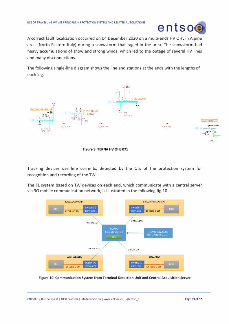
A correct fault localization occurred on 04 December 2020 on a multi-ends HV OHL in Alpine
area (North-Eastern Italy) during a snowstorm that raged in the area. The snowstorm had
heavy accumulations of snow and strong winds, which led to the outage of several HV lines
and many disconnections.
The following single-line diagram shows the line and stations at the ends with the lengths of
each leg.
Figure 9: TERNA HV OHL 071
Tracking devices use line currents, detected by the CTs of the protection system for
recognition and recording of the TW.
The FL system based on TW devices on each end, which communicate with a central server via 3G mobile communication network, is illustrated in the following fig.10.
Figure 10: Communication System from Terminal Detection Unit‘and Central Acquisition Server

USE OF TRAVELLING WAVES PRINCIPLE IN PROTECTION SYSTEM AND RELATED AUTOMATIONS
ENTSO-E | Rue de Spa, 8 | 1000 Brussels | [email protected] | www.entsoe.eu | @entso_e Page 34 of 52
A permanent fault occurred (support bracket yielded that brought the conductor in contact
with the support) and has been correctly identified with the indication of the pylon site of the
failure with the uncertainty of a span (about 400m).
Figure 11 shows the information that the system provided in real time, to the Control Room,
which was able to direct operational teams directly to the failed span.
Figure 11: Print Screen on TW Fault Localization data
The fast fault identification led to the start of the repair works after only 4 hours from the time
of the fault. In contrast, the inspection of the entire line would have required at least 48 hours
of work due to the bad weather conditions which did not permit helicopter inspections.
The tower where the fault occurred (right side), at the beginning of the repair work, is shown
below

USE OF TRAVELLING WAVES PRINCIPLE IN PROTECTION SYSTEM AND RELATED AUTOMATIONS
ENTSO-E | Rue de Spa, 8 | 1000 Brussels | [email protected] | www.entsoe.eu | @entso_e Page 35 of 52
Figure 12: Tower fault site

USE OF TRAVELLING WAVES PRINCIPLE IN PROTECTION SYSTEM AND RELATED AUTOMATIONS
ENTSO-E | Rue de Spa, 8 | 1000 Brussels | [email protected] | www.entsoe.eu | @entso_e Page 36 of 52
7 TSO’S QUESTIONNAIRE
A questionnaire was fulfilled by TSO’s represented within or contacted by ENTSO-E SG
Protection Equipment subgroup, in order know the use and challenges of operation, reliability
and maintenance of TWI-based devices.
The questionnaire was divided into three main groups:
• Application Equipment with TW algorithms
• Type of TW device
• Experience in the field
Below is a brief analysis of the return data for each question, accompanied by a histogram
representing the sum of the answers grouped by similarity or area. The TABLE 3 shows the 23
members of ENTSO-E SG Protection Equipment that fulfilled the questionnaire.
NR TSO (country) NR TSO (country)
1 APG (AT) 13 RTE (FR)
2 ESO (BG) 14 Energinet (DK)
3 EMS (SRB) 15 TenneT (NL)
4 ELES (SI) 16 TenneT (DE)
5 TEE(RO) 17 Amprion (DE)
6 EIRGRD(IE) 18 TERNA (IT)
7 AST (LV) 19 TransetBW (DE)
8 MAVIR (HU) 20 Fingrid (FI)
9 PSE (PL) 21 CEPS (CZ)
10 Swissgrid (CH) 22 SEPS (SK)
11 REE (ES) 23 REN (PT)
12 50Hz(DE)
TABLE 3: TSOs participants in questionnaire

USE OF TRAVELLING WAVES PRINCIPLE IN PROTECTION SYSTEM AND RELATED AUTOMATIONS
ENTSO-E | Rue de Spa, 8 | 1000 Brussels | [email protected] | www.entsoe.eu | @entso_e Page 37 of 52
Application equipment with TW algorithms
Q 1.1 Do you use travelling wave devices in your grid?
The first question asked TSOs whether devices that used TW principles in the network, and
were in final service, were also used as pilot projects. 22 TSOs replied and reported that most
(13/22) TSOs have not currently installed TW in operator or as pilot projects.
This shows the low diffusion of these devices, or at least the low diffusion and knowledge for
AC systems.
Figure 13: Distribution answers to Q1.1
Q1.2 Would you be willing to install some device with TW principle for either fault location or protection?
Please, describe the reason for both positive and negative answer.
With this question the interest of the TSOs in the various applications of TW devices is
evaluated. The answers give us a more precise picture in which direction the various TSOs
want to focus. A high percentage of TSOs (7/22) who do not plan to use this technology even
in the near future.

USE OF TRAVELLING WAVES PRINCIPLE IN PROTECTION SYSTEM AND RELATED AUTOMATIONS
ENTSO-E | Rue de Spa, 8 | 1000 Brussels | [email protected] | www.entsoe.eu | @entso_e Page 38 of 52
.
Figure 144: Distribution answers to Q1.2
Q1.3 In which type of network/line? (HV Cable Line; EHV Overhead Line; HVDC Link)
Breakdown on the type of lines using TW devices; most TSOs reported the use of TW devices
in overhead lines (11/22).
Figure 155: Distribution answers to Q1.3

USE OF TRAVELLING WAVES PRINCIPLE IN PROTECTION SYSTEM AND RELATED AUTOMATIONS
ENTSO-E | Rue de Spa, 8 | 1000 Brussels | [email protected] | www.entsoe.eu | @entso_e Page 39 of 52
Q1.4. On how many lines are there such devices? What is (for each line) their required function? (Fault
Localization; Protective Function; Fault discrimination for mix OHL/Cable line, Controls AR).
Subdivision by type of use. Today the use of these devices is almost exclusively for the Fault
Localization function (TWFL) (387/402 installed equipment).
Figure 166: Distribution answers to Q1.4
Q1.5. Is the system implemented in problematic portions of the network with severe climatic conditions
and/or stability, a strong presence of PEBG? (e.g. Offshore Wind Farm; EHV Sub-Marine Cable Line..etc)?
In this question, it was investigated whether TW technology is already applied in order to
overcome the problems present for fault location in orographically/climatically critical areas
or with strong PEBG penetration where protection selectivity is particularly difficult. According
to the results, no conclusions can be drawn as many TSOs have not answered this question
(10/22).

USE OF TRAVELLING WAVES PRINCIPLE IN PROTECTION SYSTEM AND RELATED AUTOMATIONS
ENTSO-E | Rue de Spa, 8 | 1000 Brussels | [email protected] | www.entsoe.eu | @entso_e Page 40 of 52
Figure 177: Distribution answers to Q1.5
Q1.6.Are you about to install some device with TW principle for either fault location or protection?
Estimated interest of the various TSOs to implement TW technology-based systems – Many
TSOs involved (9/22) do not intend to implement such systems even for test purposes.
Figure 188: Distribution answers to Q1.6

USE OF TRAVELLING WAVES PRINCIPLE IN PROTECTION SYSTEM AND RELATED AUTOMATIONS
ENTSO-E | Rue de Spa, 8 | 1000 Brussels | [email protected] | www.entsoe.eu | @entso_e Page 41 of 52
Type of TW device
Q2.1 Are the used (TW) devices integrated into systems (e.g. HVDC Control System, Station Protection and
Automation System, etc.)?
This question tends to highlight whether the devices currently installed by TW are integrated
into the various control systems or are individual dedicated systems. Most of the installed
systems are NOT integrated in systems (standing-alone device).
Figure 19: Distribution answers to Q2.1
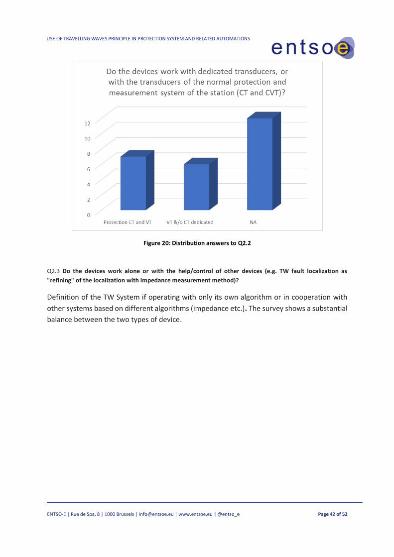
Q2.2 Do the devices work with dedicated transducers, or with the transducers of the normal protection and
measurement system of the station (CT and CVT)?
In this question highlights the type of transducers (CT & VT) used by TW devices, which as seen
in chapter 5 are one of the problems in installation and diffusion. There is substantial
equivalence between the devices installed with dedicated transducers and those using those
installed for the existing protection system.
0
5
10
Yes NO NA
Are the used (TW) devices integrated into systems (e.g. HVDC Control System, Station Protection and
Automation System, etc.)?
USE OF TRAVELLING WAVES PRINCIPLE IN PROTECTION SYSTEM AND RELATED AUTOMATIONS
ENTSO-E | Rue de Spa, 8 | 1000 Brussels | [email protected] | www.entsoe.eu | @entso_e Page 42 of 52
Figure 20: Distribution answers to Q2.2
Q2.3 Do the devices work alone or with the help/control of other devices (e.g. TW fault localization as
"refining" of the localization with impedance measurement method)?
Definition of the TW System if operating with only its own algorithm or in cooperation with
other systems based on different algorithms (impedance etc.). The survey shows a substantial
balance between the two types of device.

USE OF TRAVELLING WAVES PRINCIPLE IN PROTECTION SYSTEM AND RELATED AUTOMATIONS
ENTSO-E | Rue de Spa, 8 | 1000 Brussels | [email protected] | www.entsoe.eu | @entso_e Page 43 of 52
Figure 21: Distribution answers to Q2.3
Q2.4 Do the devices process and transmit the information themselves or TW data are transmitted to the
concentrators/central processors on which the calculation algorithm is based?
Description of the type of TW system adopted on where the fault wave recognition time
signals are processed for location determination. The systems installed are almost equally
divided between "centralised processing units and standing-alone devices".

USE OF TRAVELLING WAVES PRINCIPLE IN PROTECTION SYSTEM AND RELATED AUTOMATIONS
ENTSO-E | Rue de Spa, 8 | 1000 Brussels | [email protected] | www.entsoe.eu | @entso_e Page 44 of 52
Figure 22: Distribution answers to Q2.4
Q2.5 What kind of communication do you use?
This question investigates the type of communication between deviations and/or between
devices and the central processing system. Also, in this field there is a substantial parity of
installed systems with communication based on std. protocol. TC/IP and those with
proprietary protocol.
Figure 23: Distribution answers to Q2.5
USE OF TRAVELLING WAVES PRINCIPLE IN PROTECTION SYSTEM AND RELATED AUTOMATIONS
ENTSO-E | Rue de Spa, 8 | 1000 Brussels | [email protected] | www.entsoe.eu | @entso_e Page 45 of 52
Experience in the field
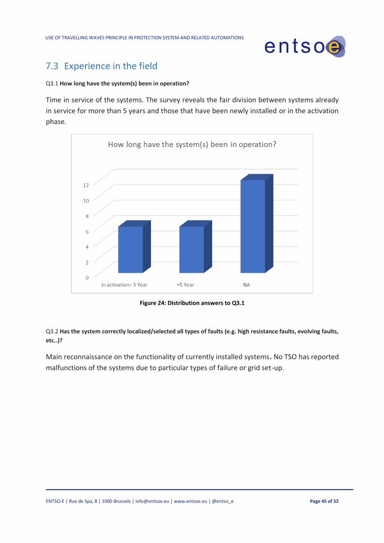
Q3.1 How long have the system(s) been in operation?
Time in service of the systems. The survey reveals the fair division between systems already
in service for more than 5 years and those that have been newly installed or in the activation
phase.
Figure 24: Distribution answers to Q3.1
Q3.2 Has the system correctly localized/selected all types of faults (e.g. high resistance faults, evolving faults,
etc..)?
Main reconnaissance on the functionality of currently installed systems. No TSO has reported
malfunctions of the systems due to particular types of failure or grid set-up.

USE OF TRAVELLING WAVES PRINCIPLE IN PROTECTION SYSTEM AND RELATED AUTOMATIONS
ENTSO-E | Rue de Spa, 8 | 1000 Brussels | [email protected] | www.entsoe.eu | @entso_e Page 46 of 52
Figure 25: Distribution answers to Q3.2
Q3.3 Is the system immune to strange operational conditions? For example, lighting strokes near a line, surge
arresters operation, switching operations…
At this point, the TW devices were required to return to operation in relation to the
"electromagnetic disturbances" generated on the line subject to protection/fault location
during lightning strikes, opening and closing of neighbouring switches, etc. Unlike the previous
survey, half of the TSOs respond that the installed systems are NOT immune and/or partially
immune to malfunctions caused by electromagnetic disturbances.
Figure 26: Distribution answers to Q3.3
0
2
4
6
8
10
12
14
Yes No data on complexfault
NA
Has the system correctly localized/selected all types of faults (e.g. high resistance faults, evolving
faults, etc..)?

USE OF TRAVELLING WAVES PRINCIPLE IN PROTECTION SYSTEM AND RELATED AUTOMATIONS
ENTSO-E | Rue de Spa, 8 | 1000 Brussels | [email protected] | www.entsoe.eu | @entso_e Page 47 of 52
Q3.4 Has the system/systems been proven to be effective in all grid setup conditions for operation. (variations
in line length/typology, variations in machinery/typology of boundary stations)?
In line with the previous analysis, also in this case about 50% of the TSOs respond that the
systems are not immune or self-adapt to heavy variations (installation of new generation
machinery, transformers, etc.) of the grid around the line.
Figure 27: Distribution answers to Q3.4
Q3.6 Do you use, or would you use a disturbance report with a sampling rate of 1 MHz? If yes, for what
purpose?
This question investigates the real use of fault recordings made with fast sampling, as
described in Chapter 5, for use of predictive maintenance switches, self-extinguishing arc
search, etc.
The answers confirm that those who have installed new generation devices (see Q3.1 >5years
old 6/22) also use this function (5/22).

USE OF TRAVELLING WAVES PRINCIPLE IN PROTECTION SYSTEM AND RELATED AUTOMATIONS
ENTSO-E | Rue de Spa, 8 | 1000 Brussels | [email protected] | www.entsoe.eu | @entso_e Page 48 of 52
Figure 28: Distribution answers to Q3.6
Q3.7 How do you test and commissioning this device, if at all?
For testing and installation, the data collected shows that about half of the TSOs who have
installed or are installing such devices in their grid perform these operations with the
company's internal resources, while the other half rely on system manufacturers.
Figure 29: Distribution answers to Q3.7
USE OF TRAVELLING WAVES PRINCIPLE IN PROTECTION SYSTEM AND RELATED AUTOMATIONS
ENTSO-E | Rue de Spa, 8 | 1000 Brussels | [email protected] | www.entsoe.eu | @entso_e Page 49 of 52
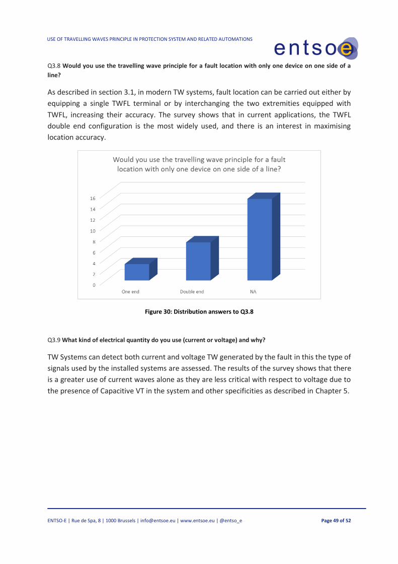
Q3.8 Would you use the travelling wave principle for a fault location with only one device on one side of a
line?
As described in section 3.1, in modern TW systems, fault location can be carried out either by
equipping a single TWFL terminal or by interchanging the two extremities equipped with
TWFL, increasing their accuracy. The survey shows that in current applications, the TWFL
double end configuration is the most widely used, and there is an interest in maximising
location accuracy.
Figure 30: Distribution answers to Q3.8
Q3.9 What kind of electrical quantity do you use (current or voltage) and why?
TW Systems can detect both current and voltage TW generated by the fault in this the type of
signals used by the installed systems are assessed. The results of the survey shows that there
is a greater use of current waves alone as they are less critical with respect to voltage due to
the presence of Capacitive VT in the system and other specificities as described in Chapter 5.

USE OF TRAVELLING WAVES PRINCIPLE IN PROTECTION SYSTEM AND RELATED AUTOMATIONS
ENTSO-E | Rue de Spa, 8 | 1000 Brussels | [email protected] | www.entsoe.eu | @entso_e Page 50 of 52
Figure 31: Distribution answers to Q3.9
0
2
4
6
8
10
12
14
Current only Voltage or both NA
What kind of electrical quantity do you use (current or voltage) and why?

USE OF TRAVELLING WAVES PRINCIPLE IN PROTECTION SYSTEM AND RELATED AUTOMATIONS
ENTSO-E | Rue de Spa, 8 | 1000 Brussels | [email protected] | www.entsoe.eu | @entso_e Page 51 of 52
8 CONCLUSION
The purpose of this report is to share operational experiences and knowledge of new
protection equipment which do not use traditional voltage and current phasors.
The report provides a general overview of the current state of the art of IED Travelling Wave
based devices and their applications. The theoretical concepts and fundamental principles of
operation of this technology and their applications for precise fault location, protection and
automation in overhead and cable lines are discussed.
A questionnaire was prepared to understand the use of TW devices and the associated
operational experience of TSOs. The analysis of the questionnaire concludes that the use of
these systems is not very widespread, and that TW devices are used mainly for fault location.
TSOs prefer relevant operational experience, supporting analyses, and integration in systems
with electromechanical or digital technology before undertaking projects to provide for the
standardisation of these applications.
A few Travelling Wave fault localisation systems are currently in operation and they have
proved their worth both in terms of accuracy and correct fault selection. There are, however,
a few TW device applications on protection systems that are in test mode (with triggers
deactivated).
From the analysis, it is also found that Travelling Wave devices are mainly used in autonomous
systems not integrated in the station protection and control systems as TSOs wait for large-
scale integration into standard Intelligent Electronic Devices (IED).
The report also concludes that systems using TW devices have extremely high-performance
and reliability, but their diffusion is still strongly limited.
It is expected, however, that in the short term all the major manufacturers will introduce more
and more IEDs equipped with TW functions in order to meet resiliency requirements and to
assist future applications in new grid scenarios (extreme weather events, decarbonisation and
transition from large conventional generation to small-distributed generation, etc).

USE OF TRAVELLING WAVES PRINCIPLE IN PROTECTION SYSTEM AND RELATED AUTOMATIONS
ENTSO-E | Rue de Spa, 8 | 1000 Brussels | [email protected] | www.entsoe.eu | @entso_e Page 52 of 52
9 REFERENCES
[1]L. V. BewleyTraveling Waves on Transmission Systems Winter Convention of the A. I. E. E., New York, 26-30,
1931.
[2] E. O. Schweitzer, III, B Kasztenny, A Guzmán, V Skendzic, and M V. Mynam “Speed of Line Protection – Can
We Break Free of Phasor Limitations? Locating Faults and Protecting Lines at the Speed of Light: Time-Domain
Principles Applied, 2018
[3] E O. Schweitzer, III, A Guzmán, M V. Mynam, V Skendzic, and B Kasztenny, “Locating Faults by the Traveling
Waves They Launch,” presented at the 2014 Texas A&M Conference for Protective Relay Engineers
[4] B. Kasztenny, A. Guzmán, N. Fischer,M V. Mynam,, D. Taylor” Practical Setting Considerations for Protective
Relays That Use Incremental Quantities and Traveling Waves” Locating Faults and Protecting Lines at theSpeed
of Light: Time-Domain Principles Applied, 2018
[5] J Rodriguez, L. Oliveira, P Jimenez, M.Nuñez, J Cardenas, Almudena Muñoz, D. Arribas Application and Results
of Travelling Wave Fault Locator (TWFL) technology applied in a 220 kV Line
[6] E. O. Schweitzer, III, A. Guzmán, M. Mynam, V. Skendzic, and B.” Accurate Single-End Fault Location and Line-
Length Estimation Using Traveling Waves” 13th International Conference on Developments in Power System
Protection, March 2016