Use of the application program - Siemens · 1.9 Application program ... Operating Sequence After...
41
s Gamma instabus Application program description January 2015 25 CO Presence Detector, Constant Contr. 920601 5WG1 258-2EB22 25 CO Presence Detector, Brightness sensor 920501 5WG1 258-2DB12 25 CO Brightness Controller 920701 5WG1 255-2DB21 Siemens AG L1V30065000B-DS02 Update: http://www.siemens.com/gamma-td Building Technologies Division Control Products and Systems ã Siemens AG 2015 P.O. 10 09 53, D-93009 Regensburg Subject to changes 1 / 41 Use of the application program Product family: Physical sensors Manufacturer: Siemens This document describes all functions; not all functions are available in all devices. Description Presence Detector, Con- stant Controller UP 258E22 Presence Detector, Brightness Sensor UP 258D12 Brightness Controller UP 255D21 Order number (MLFB) 5WG1 258-2EB22 5WG1 258-2DB12 5WG1 255-2DB21 Application 25 CO Presence Detector, Constant Contr. 920601 25 CO Presence Detec- tor, Brightness Sensor 920501 25 CO Brightness Controller 920701 Motion detector Yes Yes No Locking mode Yes No No Presence detector Yes Yes No Locking mode Yes No No HVAC detector Yes Yes No Brightness measuring Yes Yes Yes 2-level light control (switching) Yes Yes Yes Constant light level control (dimming) Yes No Yes IR receiver Yes Yes Yes Content 1 Functional description ...........................................................................................................................................................2 1.1 Presence / Motion detector ........................................................................................................................................2 1.2 Presence detector (HVAC) ..........................................................................................................................................2 1.3 Functionality of the Presence detector / Motion detector / HVAC-detector .............................................................2 1.4 Use as single device or as main detector, respectively secondary detector .............................................................3 1.5 Brightness measuring – adjustable via KNX ..............................................................................................................3 1.6 Integrated 2-level light control (switching)...............................................................................................................4 1.7 Integrated constant light level control (dimming) ....................................................................................................4 1.8 Operation via infrared (IR) remote control ................................................................................................................6 1.9 Application program................................................................................................................................................... 6 1.10 Commissioning / Factory default settings .................................................................................................................6 2 Parameter and Communication objects ................................................................................................................................8 2.1 General .......................................................................................................................................................................8 2.2 Brightness measuring.................................................................................................................................................9 2.3 Motion detector / Presence detector .......................................................................................................................10 2.4 HVAC-Presence detector ..........................................................................................................................................20 2.5 2-level light controller (on-off) ................................................................................................................................27 2.6 Constant light level control continuous...................................................................................................................29 2.7 IR–Decoder ...............................................................................................................................................................35 3 Appendix ..............................................................................................................................................................................39 3.1 Determination of the correction factor of the brightness sensor (calibration) ......................................................39 3.2 Determination of the control characteristic ............................................................................................................39 3.3 Determination of characteristic of used lights in the room ....................................................................................40 3.4 Example of configuration.........................................................................................................................................40
Transcript of Use of the application program - Siemens · 1.9 Application program ... Operating Sequence After...

s Gamma instabus
Application program description
January 2015
25 CO Presence Detector, Constant Contr. 920601 5WG1 258-2EB2225 CO Presence Detector, Brightness sensor 920501 5WG1 258-2DB1225 CO Brightness Controller 920701 5WG1 255-2DB21
Siemens AG L1V30065000B-DS02 Update: http://www.siemens.com/gamma-tdBuilding Technologies DivisionControl Products and Systems ã Siemens AG 2015P.O. 10 09 53, D-93009 Regensburg Subject to changes 1 / 41
Use of the application program
Product family: Physical sensorsManufacturer: Siemens
This document describes all functions; not all functions are available in all devices.Description Presence Detector, Con-
stant Controller UP258E22
Presence Detector,Brightness SensorUP 258D12
Brightness ControllerUP 255D21
Order number (MLFB) 5WG1 258-2EB22 5WG1 258-2DB12 5WG1 255-2DB21Application 25 CO Presence Detector,
Constant Contr. 92060125 CO Presence Detec-tor, Brightness Sensor920501
25 CO Brightness Controller920701
Motion detector Yes Yes NoLocking mode Yes No NoPresence detector Yes Yes NoLocking mode Yes No NoHVAC detector Yes Yes NoBrightness measuring Yes Yes Yes2-level light control(switching)
Yes Yes Yes
Constant light level control(dimming)
Yes No Yes
IR receiver Yes Yes Yes
Content
1 Functional description ........................................................................................................................................................... 2
1.1 Presence / Motion detector ........................................................................................................................................ 21.2 Presence detector (HVAC) .......................................................................................................................................... 21.3 Functionality of the Presence detector / Motion detector / HVAC-detector ............................................................. 21.4 Use as single device or as main detector, respectively secondary detector ............................................................. 31.5 Brightness measuring – adjustable via KNX .............................................................................................................. 31.6 Integrated 2-level light control (switching) ............................................................................................................... 41.7 Integrated constant light level control (dimming) .................................................................................................... 41.8 Operation via infrared (IR) remote control ................................................................................................................ 61.9 Application program................................................................................................................................................... 61.10 Commissioning / Factory default settings ................................................................................................................. 6
2 Parameter and Communication objects ................................................................................................................................ 8
2.1 General ....................................................................................................................................................................... 82.2 Brightness measuring ................................................................................................................................................. 92.3 Motion detector / Presence detector ....................................................................................................................... 102.4 HVAC-Presence detector .......................................................................................................................................... 202.5 2-level light controller (on-off) ................................................................................................................................ 272.6 Constant light level control continuous................................................................................................................... 292.7 IR–Decoder ............................................................................................................................................................... 35
3 Appendix .............................................................................................................................................................................. 39
3.1 Determination of the correction factor of the brightness sensor (calibration) ...................................................... 393.2 Determination of the control characteristic ............................................................................................................ 393.3 Determination of characteristic of used lights in the room .................................................................................... 403.4 Example of configuration ......................................................................................................................................... 40

Gamma instabus
Application program description
January 2015
25 CO Presence detector, Constant light 920601 5WG1 258-2EB2225 CO Presence detector, brightness sensor 920501 5WG1 258-2DB1225 CO Brightness Controller 920701 5WG1 255-2DB21
Update: http://www.siemens.com/gamma-td L1V30065000B-DS02 Siemens AGBuilding Technologies Division
ã Siemens AG 2015 Control Products and Systems2 / 41 Subject to changes P.O. 10 09 53, D-93009 Regensburg
1 Functional description
The device is a presence/motion detector with integrated constant light level control. The device communicates via KNXwith actuators or other KNX devices. It is designed for mounting on the ceiling. Owing to its tilting sensor head, the de-vice can be aligned with the required capture area. The main application for the device is automatic control of the lightingon an office workplace.
1.1 Presence / Motion detector
The detector senses the presence of a person or that there is no longer anyone in its detection area. The detector signalcan be analyzed via two separate communication channels, termed motion detector and presence detector. The detectionrange is identical for all channels. Each channel can be locked individually via objects.
1.2 Presence detector (HVAC)
The detector has an additional control output for HVAC applications.
For example, this function can switch systems that are used for heating, ventilating and climate control (HVAC) of theroom from “Energy saving mode” in an unused room to “Comfort mode” in an occupied room and back to “Energy savingmode”, when the room is again unoccupied.
Fig. 1 Three independent configuration detector channels for different applications
1.3 Functionality of the Presence detector / Motion detector / HVAC-detector
For each detector channel 4 communication objects are available, in sum 12 different communication objects. It is possi-ble to send one or two KNX telegrams at the beginning and at the end of a detected presence, according to configuration.The values of the communication objects are configured for each functional block (motion detector, presence detector,HVAC-detector) via corresponding parameters.

Gamma instabus
Application program description
January 2015
25 CO Presence detector, Constant light 920601 5WG1 258-2EB2225 CO Presence detector, brightness sensor 920501 5WG1258-2DB1225 CO Brightness Controller 920701 5WG1 255-2DB21
Siemens AG L1V30065000B-DS02 Update: http://www.siemens.com/gamma-tdBuilding Technologies DivisionControl Products and Systems ã Siemens AG 2015P.O. 10 09 53, D-93009 Regensburg Subject to changes 3 / 41
Motion
A B C DBus telegram
dead timeOvershoot time
A
Fig. 2 Flowchart
Each time a presence is detected, the overshoot time is started. Its duration is configurable for each functional block sepa-rately. The end of presence is determined by the end of the overshoot time.The duration of the dead time is also configurable per functional block. It is used to protect the actuators that are con-nected to the detector. If a presence is detected during the dead time, neither telegrams are sent nor the overshoot timeis started.In the following the telegrams, which are send at the beginning of a presence, are called A and B, the telegrams, whichare sent at the end of a presence, are called C and D.
Operating SequenceAfter the device has detected a presence, telegram A is sent immediately. If it has been configured to send also a tele-gram B, then telegram B is sent after the configured time (optionally also cyclically).If there are no motions any more, at the end of the overshoot time telegram C and (if configured) telegram D are sent.Telegram D can also be sent cyclically.
If there are motions during the overshoot time is running, the overshoot time is restarted.
1.4 Use as single device or as main detector, respectively secondary detector
The detector can be operated as an independent device, as the main or secondary detector.
According to the requirement, additional presence detectors can be connected with the “main detector” via KNX as “sec-ondary detectors” to extend the presence detection zone. “Secondary detectors” supply motion information only to themain detector.
1.5 Brightness measuring – adjustable via KNX
The device contains an independent light sensor. The signal measured there is available both at the KNX and internally.
Because the light sensor measures directly, it must be possible to calibrate it for indirect measurement, so that it can beadapted to the different installation sites. Rapid brightness fluctuations are filtered out. The measurement range of the in-ternal light sensor is between 20 and 1000 lux.
Fig. 3 indirect brightness measuring
ind
irect

Gamma instabus
Application program description
January 2015
25 CO Presence detector, Constant light 920601 5WG1 258-2EB2225 CO Presence detector, brightness sensor 920501 5WG1 258-2DB1225 CO Brightness Controller 920701 5WG1 255-2DB21
Update: http://www.siemens.com/gamma-td L1V30065000B-DS02 Siemens AGBuilding Technologies Division
ã Siemens AG 2015 Control Products and Systems4 / 41 Subject to changes P.O. 10 09 53, D-93009 Regensburg
The settings determine whether the brightness value computed by the device or a brightness value received from outsideis used for the detector's remaining functional blocks.For indirect brightness measuring a maximal distance of 2,8 m is recommended. In case of larger distances the measuringcan be realized via a reference area with 2,8 m distance.
1.6 Integrated 2-level light control (switching)
If the brightness controller is enabled (automatic mode) the lighting is switched on as soon as the brightness falls below aset lower threshold. The lighting is switched off if the set upper brightness threshold is exceeded. The brightness thresh-olds are variable either via parameters or via communication objects.
The controller can also be operated semi-automatically by separating into two individual switching objects for exceedingor falling below the threshold. In this way, it can be switched to “Only on” or “Only off.”
If the controller receives a switching or dimming command via the associated communication object over KNX, then thisis deemed an external override and the controller switches automatic mode off. This change of status is sent simultane-ously on the bus via the “Automatic Status” object.
1.7 Integrated constant light level control (dimming)
The luminance of the day light falling through a window into a room decreases in the room with the distance from thewindow.
Fig. 4 Principal of constant light level control with five luminaries
Depending on lamp type, the lighting is controlled to the preset brightness value via dimming actuators or switch-ing/dimming actuators. The brightness setpoint may be configured via a parameter or set via a communication object.
For optimum use of the day light penetrating the room the presence detector with constant light level control offers theoption to control a main lighting group directly and up to four additional lighting control groups each via their own char-acteristic curve and their own controller (master/slave operation).All lighting groups are dimmed to the same set point value. This allows controlling the light level in a room with only onepresence detector with constant light level control. Depending on the relative distance of the additional lighting groups tothe window compared to the main lighting group, each of these additional lighting groups has to be dimmed brighter ordarker than the main lighting group.
Firstly, this requires determining the installation position of the presence detector. The presence detector can be installedon the ceiling at any of the positions A –E. The position of the presence detector determining the main lighting group is inprinciple freely selectable. Yet, it should be close to the window allowing the best measurement of the daylight contribu-tion.
Daylight
Artificiallight

Gamma instabus
Application program description
January 2015
25 CO Presence detector, Constant light 920601 5WG1 258-2EB2225 CO Presence detector, brightness sensor 920501 5WG1258-2DB1225 CO Brightness Controller 920701 5WG1 255-2DB21
Siemens AG L1V30065000B-DS02 Update: http://www.siemens.com/gamma-tdBuilding Technologies DivisionControl Products and Systems ã Siemens AG 2015P.O. 10 09 53, D-93009 Regensburg Subject to changes 5 / 41
Fig. 5 Position of lighting groups A-E
For master/slave operation the day light curve under lighting groups A – E has to be captured. For this purpose the artifi-cial lighting has to be completely turned off, such that just the natural day light is illuminating the room. Ideally, the daylight is evenly falling into the room (no sharp shade / sunlight edges), bright, and diffused, e.g. at noon on a bright daywith overcast sky. Under each lighting group the luminance (Lux) has to be measured manually and these values have tobe entered into ETS.
Fig. 6 Parameters for measured brightness values
The control characteristic curve for the additional lighting groups has to be determined without day light. For that pur-pose the room has to be completely darkened or the characteristic curve has to be determined at night. Sending a startsignal to communication object 71 starts the determination of the characteristic curves. The presence detector automati-cally generates 15 discrete control values in the range 0%...100% for each constant light level controller of the main andadditional lighting groups. The controllers send dimming values to the corresponding lighting groups and the presencedetector measures the resulting luminance level. The period for the measurement can be configured between 10 and 60seconds to allow for optimal pre-heating of the lamps.
Fig. 7 Parameters for control characteristics
After successful completion or interruption of the calibration run the controller is in the state „inactive“.In case of successful completion the lighting groups are set to 50%, in case of a failure to minimum value ~ 6%.

Gamma instabus
Application program description
January 2015
25 CO Presence detector, Constant light 920601 5WG1 258-2EB2225 CO Presence detector, brightness sensor 920501 5WG1 258-2DB1225 CO Brightness Controller 920701 5WG1 255-2DB21
Update: http://www.siemens.com/gamma-td L1V30065000B-DS02 Siemens AGBuilding Technologies Division
ã Siemens AG 2015 Control Products and Systems6 / 41 Subject to changes P.O. 10 09 53, D-93009 Regensburg
During operation the constant light level controller can take up to four different states:Active: In this state the constant lighting control is active. In a configurable period the controller compares set point andactual values and sends a control value.Inactive: In the state the controller is passive. The controller does not compare set point value and actual value and doesnot send control values.Stand-by: In this state the controller is passive. Different from the state “inactive” it still compares the set point value withthe actual value. On a corresponding difference between set point value and actual value the controller automaticallyswitches to the active state.Off: The controller function is stopped and actuators for main and additional lighting groups are first dimmed to a mini-mum and then completely turned off a second later.
Behavior on bus voltage failure / recoveryOn bus voltage failure the current setpoint value is saved.On bus voltage recovery the setpoint value is restored. The controller is in the state OFF.
1.8 Operation via infrared (IR) remote control
The IR receiver integrated in the presence detector can control light and shade, as well as store and call up scenes via aspecial IR remote control.The IR commands implemented can be combined via communication objects with the other function blocks or used tocontrol other devices.The integrated IR receiver-decoder can be controlled only with one of the Siemens IR remote controls shown below. Theremote controls have a range of about 10 meters.
The functionality of button pairs A to F (see above diagram) will be configured via the ETS.Channel F can be used optional to enable / disable the programming mode.
1.9 Application program
You need the KNX Engineering Tool Software (ETS) version 3.0 f and higher to load the application program.
1.10 Commissioning / Factory default settings
After programming the device starts up with a warm-up phase of about 40 seconds.
Factory default settingsIn the factory default state, the parameter Operating Mode is set to Setting Mode.While the device is in "Setting Mode", the integrated programming LED displays the PIR sensor state. (illuminates brieflywith motion)In factory default setting the programming mode can be enabled and disabled via IR remote control (5WG1 255-7AB11)channel F.

Gamma instabus
Application program description
January 2015
25 CO Presence detector, Constant light 920601 5WG1 258-2EB2225 CO Presence detector, brightness sensor 920501 5WG1258-2DB1225 CO Brightness Controller 920701 5WG1 255-2DB21
Siemens AG L1V30065000B-DS02 Update: http://www.siemens.com/gamma-tdBuilding Technologies DivisionControl Products and Systems ã Siemens AG 2015P.O. 10 09 53, D-93009 Regensburg Subject to changes 7 / 41
Programming modeA short press of the learning button (< 2 s) enables the programming mode. This is indicated by the programming key(LED). An additional press disables the programming mode.
Factory settings (only UP 255D21 and UP 258D12)A very long press of the learning button (> 20 s) sets the device to factory default. This will be indicated by a continuousflashing of the programming LED for ~ 8 s.
Note (only UP 255D21 and UP 258D12)A long press of the learning button (> 5 s to 20 s) enables the connection test for commissioning with Desigo. This modewill be disabled by an additional short press of the learning button.
Behaviour after programmingThe behavior of the device after programming with the ETS is dependent on the configuration.
Gamma instabus
Application program description
January 2015
25 CO Presence detector, Constant light 920601 5WG1 258-2EB2225 CO Presence detector, brightness sensor 920501 5WG1 258-2DB1225 CO Brightness Controller 920701 5WG1 255-2DB21
Update: http://www.siemens.com/gamma-td L1V30065000B-DS02 Siemens AGBuilding Technologies Division
ã Siemens AG 2015 Control Products and Systems8 / 41 Subject to changes P.O. 10 09 53, D-93009 Regensburg
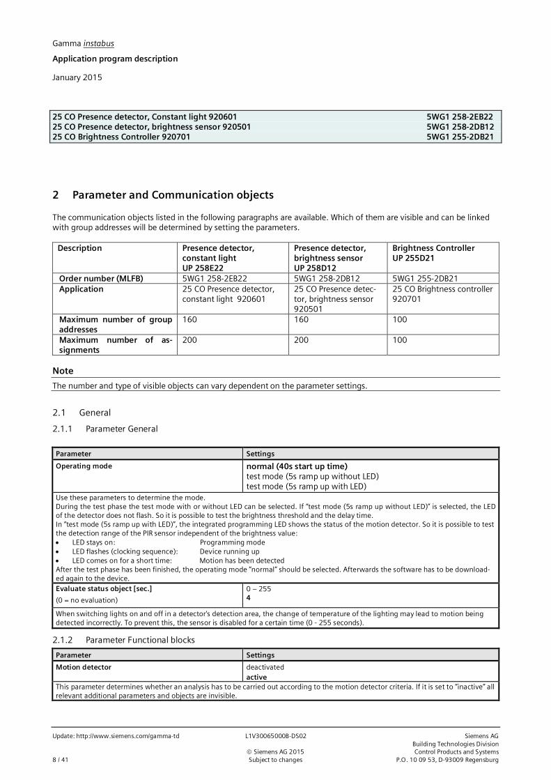
2 Parameter and Communication objects
The communication objects listed in the following paragraphs are available. Which of them are visible and can be linkedwith group addresses will be determined by setting the parameters.
Description Presence detector,constant lightUP 258E22
Presence detector,brightness sensorUP 258D12
Brightness ControllerUP 255D21
Order number (MLFB) 5WG1 258-2EB22 5WG1 258-2DB12 5WG1 255-2DB21Application 25 CO Presence detector,
constant light 92060125 CO Presence detec-tor, brightness sensor920501
25 CO Brightness controller920701
Maximum number of groupaddresses
160 160 100
Maximum number of as-signments
200 200 100
Note
The number and type of visible objects can vary dependent on the parameter settings.
2.1 General
2.1.1 Parameter General
Parameter Settings
Operating mode normal (40s start up time)test mode (5s ramp up without LED)test mode (5s ramp up with LED)
Use these parameters to determine the mode.During the test phase the test mode with or without LED can be selected. If “test mode (5s ramp up without LED)” is selected, the LEDof the detector does not flash. So it is possible to test the brightness threshold and the delay time.In “test mode (5s ramp up with LED)”, the integrated programming LED shows the status of the motion detector. So it is possible to testthe detection range of the PIR sensor independent of the brightness value:· LED stays on: Programming mode· LED flashes (clocking sequence): Device running up· LED comes on for a short time: Motion has been detectedAfter the test phase has been finished, the operating mode “normal” should be selected. Afterwards the software has to be download-ed again to the device.Evaluate status object [sec.]
(0 = no evaluation)
0 – 2554
When switching lights on and off in a detector's detection area, the change of temperature of the lighting may lead to motion beingdetected incorrectly. To prevent this, the sensor is disabled for a certain time (0 - 255 seconds).
2.1.2 Parameter Functional blocks
Parameter Settings
Motion detector deactivatedactive
This parameter determines whether an analysis has to be carried out according to the motion detector criteria. If it is set to “inactive” allrelevant additional parameters and objects are invisible.

Gamma instabus
Application program description
January 2015
25 CO Presence detector, Constant light 920601 5WG1 258-2EB2225 CO Presence detector, brightness sensor 920501 5WG1258-2DB1225 CO Brightness Controller 920701 5WG1 255-2DB21
Siemens AG L1V30065000B-DS02 Update: http://www.siemens.com/gamma-tdBuilding Technologies DivisionControl Products and Systems ã Siemens AG 2015P.O. 10 09 53, D-93009 Regensburg Subject to changes 9 / 41
Parameter Settings
Presence detector deactivatedactive
This parameter determines whether an analysis has to be carried out according to the presence detector criteria. If it is set to “inactive”all relevant additional parameters and objects are invisible.Presence detector (HVAC) (Heating, Ventilating, AirConditioning)
deactivatedactive
This parameter determines whether an analysis has to be carried out according to the criteria for HVAC control. If it is set to “inactive”all relevant additional parameters and objects are invisible.
Light control (on-off) activedeactivated
This parameter determines whether an analysis has to be carried out according to the criteria for light control. If it is set to “inactive” allrelevant additional parameters and objects are invisible.
Constant light level control continuous deactivatedactive
This parameter determines whether an analysis has to be carried out according to the criteria for constant light level control. If it is setto “inactive” all relevant additional parameters and objects are invisible.
IR-Decoder deactivatedactive
This parameter determines whether an analysis has to be carried out according to the signals received from the IR decoder. If it is set to“inactive” all relevant additional parameters and objects are invisible.
2.1.3 General object
Obj.-no. Object name Function Type Flags
0 Status of switching actuator On/Off 1 bit CRWT
This object notifies the detector whether the actuator controlled by the device has switched. If a change of status (1->0 or 0->1) hasoccurred, then the sensor is not analyzed for a configurable time. This prevents the detector sensing the fall in temperature of an in-candescent lamp that has just been switched off as motion.
2.2 Brightness measuring
2.2.1 Parameter
Parameter Settings
Measuring method of internal light sensor indirect (calibration by user)
The internal light sensor can only measure directly. The light level on the desk can be determined indirectly by recomputing, if the pa-rameter is set accordingly. For this, the detector's brightness measurement function must be calibrated.
Calibration via objectwith adjustment factor
Calibration is carried out either via an object (no. 27) or via adjustment factor.
Adjustment factor (x 0.1) 1 - 200, 10This parameter is visible only if the parameter “Calibration” is set to “with adjustment factor.”In this case, the light measured by the light sensor is multiplied by 0.1 of the set adjustment factor.
Number of values for calculation of average 1; 2; 4; 8
The internal light sensor measures every second. For brightness measurement, the mean value can be formed from several valuesmeasured consecutively. The number of values to be used to form the mean value is determined via the above parameter.
Send brightness value cyclically no1 second5 seconds10 seconds30 seconds1 minute
This parameter determines whether and at what intervals the brightness value determined is sent via the bus.

Gamma instabus
Application program description
January 2015
25 CO Presence detector, Constant light 920601 5WG1 258-2EB2225 CO Presence detector, brightness sensor 920501 5WG1 258-2DB1225 CO Brightness Controller 920701 5WG1 255-2DB21
Update: http://www.siemens.com/gamma-td L1V30065000B-DS02 Siemens AGBuilding Technologies Division
ã Siemens AG 2015 Control Products and Systems10 / 41 Subject to changes P.O. 10 09 53, D-93009 Regensburg
Parameter Settings
Send brightness value on change noat small changeat medium changeat large change
This parameter determines whether the brightness value is sent automatically and immediately when it changes.
2.2.2 Communication objects
Obj.-no. Object name Function Type Flags
25 Brightness value(internal)
value in LUX 2 Byte9.004
CRWT
This object sends its brightness value to the brightness measuring device. If cyclical sending is switched off, then the value can be de-termined via the bus with a read query.The measurement range for the internal light sensor is between 20 and 1000 LUX.This value can be changed by calibration.The upper limit for the internal brightness value after calibration is 20000 LUX.
26 Brightness value(extern)
value in LUX 2 Byte9.004
CRW
This object feeds a value from an external brightness measuring device.
27 Brightness value(calibration)
value in LUX 2 Byte9.004
CRW
Because the light sensor measures only the light reflected from the desk, it can be calibrated.During calibration, the brightness value in the room in which the device has been mounted should be that used later as the setpoint forconstant lighting control.The ETS (diagnostic mode -> send telegram) is used to send the previously measured value to the device via the above object.The measured value is entered as a decimal number in the entry field of the ETS. The ETS codes this value as DPT 9.004 (EIS5) andsends it to the device. As soon as the value has been received, the adjustment factor is computed from it (brightness value = adjust-ment factor * measured value).If the parameter “Measuring method of the internal light sensor” has been set to “indirect,” the recomputed value is output as the in-ternal brightness value.Note 1: When calibrating object 27, plausibility checks are carried out. If the value communicated via the object is more than 20 timesthe value measured by the internal light sensor, the adjustment factor is set to 1. It is the same if a value above the internal brightnessvalue (20,000 LUX) is transferred.In case of a received telegram with 0 LUX the factor will be reset to “1” (= factory settings).Note 2: Owing to rounding errors, the measured and recomputed brightness value (“Internal brightness value”) can differ slightly fromthe value recorded with the external measuring device.Note 3: The controller works only properly if the calibration procedure was successful and is stored within the flash memory.After a firmware update the factor and the control characteristic remains.
2.3 Motion detector / Presence detector
2.3.1 Parameter
In the following paragraphs the parameters for the functional block „Motion detector“ are described. The configuration forthe functional block „Presence detector“ is performed similar.
Parameter Settings
Lock motion sensor via comm-object noyes
This parameter determines if the motion detector can be locked and unlocked via a communication object.

Gamma instabus
Application program description
January 2015
25 CO Presence detector, Constant light 920601 5WG1 258-2EB2225 CO Presence detector, brightness sensor 920501 5WG1258-2DB1225 CO Brightness Controller 920701 5WG1 255-2DB21
Siemens AG L1V30065000B-DS02 Update: http://www.siemens.com/gamma-tdBuilding Technologies DivisionControl Products and Systems ã Siemens AG 2015P.O. 10 09 53, D-93009 Regensburg Subject to changes 11 / 41
Parameter Settings
Value of locking object after bus voltage recovery Off (0)On (1)as before bus voltage failurequery via bus
This parameter determines what the value of the locking communication object will be after bus voltage recovery.
Locking is active if locking object = 0if locking object = 1
This parameter determines how the value of the locking communication object is analyzed.
Locking object acts on sensorobjects (A-B-C-D) (UP 258E22 only)
This parameter defines the behavior of the lock.:
Sensor: When ‘locked’, the sensor itself is disabled. If the overshoot timer has already started (detector switched on), the overshoottimer will be continued and after the overshoot time the detector switches off (sends C-D). Retriggering through the detector is notpossible as long the lock is set. Retriggering via the extension object is still possible.
Objects: When ‘locked’ the output communication objects A-B and C-D of the detector will be controlled. Triggering via the extensionobject is still possible.
Behaviour if lock is enabled detector switches ON, sends A-Bdetector switches OFF, sends C-Ddetector sends no telegram
This parameter is visible only when parameter “Lock acts on” is set to “objects (A-B-C-D)“.
detector sends no telegram: Throughout the entire time that the detector has been ‘locked’, it is still passively monitoring to detectmotion, but just not sending any of the associated telegrams.This parameter has the following parameter set:
Behaviour if lock is disabled detector sends current status A-B or C-D)detector sends no telegram
detector sends current status (A-B or C-D): If the lock is disabled the detector sends the current status includingthe overshoot time left. This behaviour is used for applications “silent mode”, during locking phase no telegrams willbe sent.Detector sends no telegrams: If the lock is disabled no telegram will be sent at all. The device enters normal modeagain only in case of a new presence detection.
detector switches ON, sends A-B: When the detector is ‘locked’ telegrams A(B) are sent. However no telegrams will be sent if theovershoot timer was active prior to ‘locking’. This mode is useful for “continuous ON” applications.This parameter has the following parameter set:
Behaviour if lock is disabled detector switches delay off, sends C-Ddetector switches at once off, sends C-D
Detector switches delay off, sends C-D: The overshoot timer will be restarted after Retriggering via the extensionobject is still possible. ‘unlock’. If no motion is detected after ‘unlocking’ the detector sends C(D) after the overshoottime . If motion is detected after ‘unlocking’ the overshoot time is retriggered.
Detector switches at once off, sends C-D: Telegrams C(D) are sent at once. After unlocking between A and B, Bwill not be sent, but C-D immediately.

Gamma instabus
Application program description
January 2015
25 CO Presence detector, Constant light 920601 5WG1 258-2EB2225 CO Presence detector, brightness sensor 920501 5WG1 258-2DB1225 CO Brightness Controller 920701 5WG1 255-2DB21
Update: http://www.siemens.com/gamma-td L1V30065000B-DS02 Siemens AGBuilding Technologies Division
ã Siemens AG 2015 Control Products and Systems12 / 41 Subject to changes P.O. 10 09 53, D-93009 Regensburg
Parameter Settings
detector switches OFF, sends C-D: when the detector is locked telegrams C(D) are sent only if the overshoot timer was already active,otherwise no telegrams are sent. This mode is useful for “continuous OFF” applications. This parameter has the following parameterset:
Behaviour if lock is disabled detector sends no telegramdetector sends current status (A-B or C-D)
Detector sends no telegrams: : If the lock is disabled no telegram will be sent at all.
Motion detection up to brightness level 2Luxup to brightness level 5Luxup to brightness level 10Luxup to brightness level 15Luxup to brightness level 20Luxup to brightness level 50Luxup to brightness level 100Luxup to brightness level 200Luxup to brightness level 500Luxup to brightness level 1000Luxbrightness independent
This parameter controls the reporting of a motion dependent on the ambient brightness. If a movement has already been detected(overshoot time running), then there is no further analysis of the ambient brightness. In other words, if further motions are detectedduring a detected motion, then the overshoot time is restarted.
Source for brightness value internal valueexternal value
This parameter determines which brightness value is used for analyzing the brightness threshold. If this parameter is set to “Internalvalue” the value of the brightness sensor inside the device is used. If “External value,” the value from the communication object is used.This value is reproduced at bus voltage recovery and used until it is overwritten by the bus.
Device works as single or master deviceslave
This parameter determines whether the detector is used as a standalone device or as a master or as a slave in conjunction with othermotion sensors.
Value of locking object after bus voltage recovery offonas before bus voltage failurequery via bus
This parameter is visible only if the parameter “Lock motion detector via object” is not set to “No.”This parameter determines with which value the object “Motion detector lock” is initialized.
2.3.1.1 Begin of Motion
The following parameters are visible only if the device is working as a standalone device or as a master (parameter “Deviceworks as” is set to “Single or master device”).
Parameter Settings
If motion is detected, send (A) no telegramOnOff8-bit value8-bit value (selectable) (UP 258E22 only)scene recall16-bit value (decimal)16-bit value (temperature)16-bit value (brightness)
This parameter determines whether a telegram is sent after a motion is detected and what format the telegram has.
Send second telegram (B) noyes
This parameter determines whether a second telegram is sent after a delay to the first.
Gamma instabus
Application program description
January 2015
25 CO Presence detector, Constant light 920601 5WG1 258-2EB2225 CO Presence detector, brightness sensor 920501 5WG1258-2DB1225 CO Brightness Controller 920701 5WG1 255-2DB21
Siemens AG L1V30065000B-DS02 Update: http://www.siemens.com/gamma-tdBuilding Technologies DivisionControl Products and Systems ã Siemens AG 2015P.O. 10 09 53, D-93009 Regensburg Subject to changes 13 / 41
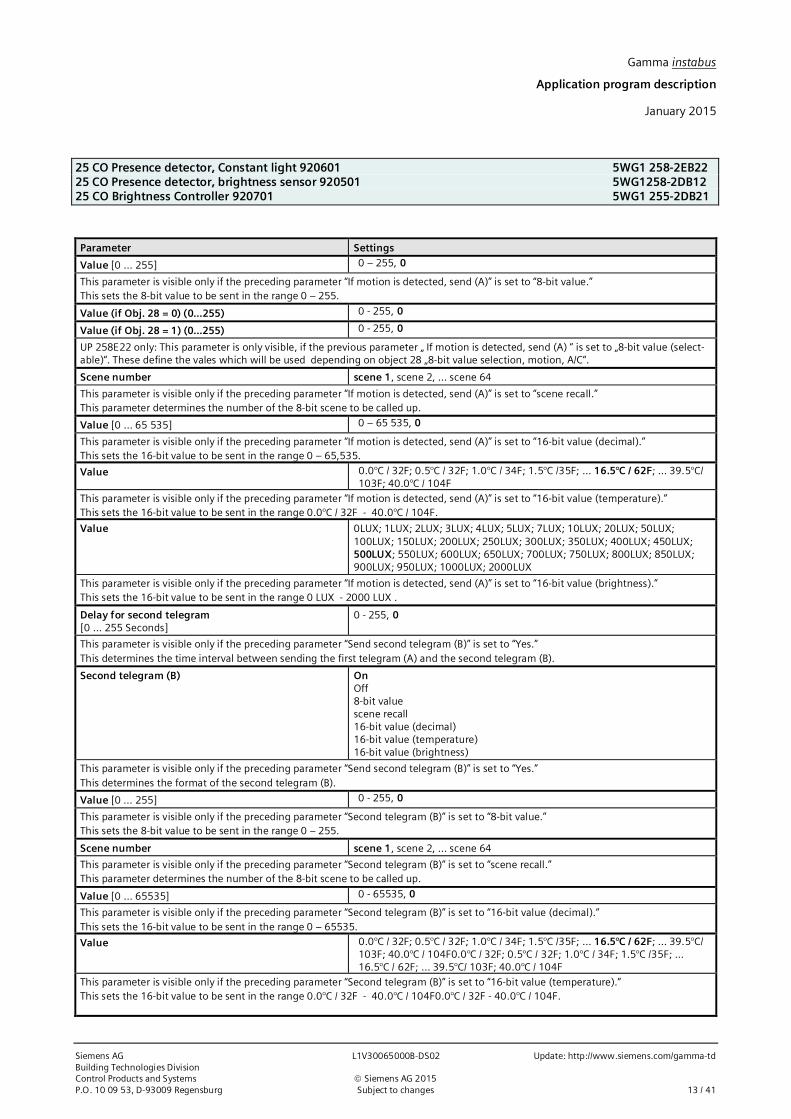
Parameter Settings
Value [0 … 255] 0 – 255, 0
This parameter is visible only if the preceding parameter “If motion is detected, send (A)” is set to “8-bit value.”This sets the 8-bit value to be sent in the range 0 – 255.
Value (if Obj. 28 = 0) (0…255) 0 - 255, 0
Value (if Obj. 28 = 1) (0…255) 0 - 255, 0
UP 258E22 only: This parameter is only visible, if the previous parameter „ If motion is detected, send (A) “ is set to „8-bit value (select-able)“. These define the vales which will be used depending on object 28 „8-bit value selection, motion, A/C“.
Scene number scene 1, scene 2, … scene 64
This parameter is visible only if the preceding parameter “If motion is detected, send (A)” is set to “scene recall.”This parameter determines the number of the 8-bit scene to be called up.
Value [0 … 65 535] 0 – 65 535, 0
This parameter is visible only if the preceding parameter “If motion is detected, send (A)” is set to “16-bit value (decimal).”This sets the 16-bit value to be sent in the range 0 – 65,535.
Value 0.0°C / 32F; 0.5°C / 32F; 1.0°C / 34F; 1.5°C /35F; … 16.5°C / 62F; … 39.5°C/103F; 40.0°C / 104F
This parameter is visible only if the preceding parameter “If motion is detected, send (A)” is set to “16-bit value (temperature).”This sets the 16-bit value to be sent in the range 0.0°C / 32F - 40.0°C / 104F.
Value 0LUX; 1LUX; 2LUX; 3LUX; 4LUX; 5LUX; 7LUX; 10LUX; 20LUX; 50LUX;100LUX; 150LUX; 200LUX; 250LUX; 300LUX; 350LUX; 400LUX; 450LUX;500LUX; 550LUX; 600LUX; 650LUX; 700LUX; 750LUX; 800LUX; 850LUX;900LUX; 950LUX; 1000LUX; 2000LUX
This parameter is visible only if the preceding parameter “If motion is detected, send (A)” is set to “16-bit value (brightness).”This sets the 16-bit value to be sent in the range 0 LUX - 2000 LUX .
Delay for second telegram[0 … 255 Seconds]
0 - 255, 0
This parameter is visible only if the preceding parameter “Send second telegram (B)” is set to “Yes.”This determines the time interval between sending the first telegram (A) and the second telegram (B).
Second telegram (B) OnOff8-bit valuescene recall16-bit value (decimal)16-bit value (temperature)16-bit value (brightness)
This parameter is visible only if the preceding parameter “Send second telegram (B)” is set to “Yes.”This determines the format of the second telegram (B).
Value [0 … 255] 0 - 255, 0
This parameter is visible only if the preceding parameter “Second telegram (B)” is set to “8-bit value.”This sets the 8-bit value to be sent in the range 0 – 255.
Scene number scene 1, scene 2, … scene 64
This parameter is visible only if the preceding parameter “Second telegram (B)” is set to “scene recall.”This parameter determines the number of the 8-bit scene to be called up.
Value [0 … 65535] 0 - 65535, 0
This parameter is visible only if the preceding parameter “Second telegram (B)” is set to “16-bit value (decimal).”This sets the 16-bit value to be sent in the range 0 – 65535.
Value 0.0°C / 32F; 0.5°C / 32F; 1.0°C / 34F; 1.5°C /35F; … 16.5°C / 62F; … 39.5°C/103F; 40.0°C / 104F0.0°C / 32F; 0.5°C / 32F; 1.0°C / 34F; 1.5°C /35F; …16.5°C / 62F; … 39.5°C/ 103F; 40.0°C / 104F
This parameter is visible only if the preceding parameter “Second telegram (B)” is set to “16-bit value (temperature).”This sets the 16-bit value to be sent in the range 0.0°C / 32F - 40.0°C / 104F0.0°C / 32F - 40.0°C / 104F.

Gamma instabus
Application program description
January 2015
25 CO Presence detector, Constant light 920601 5WG1 258-2EB2225 CO Presence detector, brightness sensor 920501 5WG1 258-2DB1225 CO Brightness Controller 920701 5WG1 255-2DB21
Update: http://www.siemens.com/gamma-td L1V30065000B-DS02 Siemens AGBuilding Technologies Division
ã Siemens AG 2015 Control Products and Systems14 / 41 Subject to changes P.O. 10 09 53, D-93009 Regensburg
Parameter Settings
Value 0LUX; 1LUX; 2LUX; 3LUX; 4LUX; 5LUX; 7LUX; 10LUX; 20LUX; 50LUX;100LUX; 150LUX; 200LUX; 250LUX; 300LUX; 350LUX; 400LUX; 450LUX;500LUX; 550LUX; 600LUX; 650LUX; 700LUX; 750LUX; 800LUX; 850LUX;900LUX; 950LUX; 1000LUX; 2000LUX
This parameter is visible only if the preceding parameter “Second telegram (B)” is set to “16-bit value (brightness).”This sets the 16-bit value to be sent in the range 0 LUX - 2000 LUX .
Send second telegram (B) cyclically no1 second5 seconds10 seconds30 seconds1 minute
If you want the second telegram (B) to be sent cyclically after a motion is detected, then this parameter must be set to the correspond-ing value.
The following parameter is visible only if the device is working as a slave (parameter “Device works as” is set to “Slave”).
Parameter Settings
Send trigger telegrams cyclically no1 second5 seconds10 seconds30 seconds1 minute
A device in slave mode can only send an “On telegram” to the master if motion has been detected to trigger this via the secondary in-put. The internal overshoot time of 10 seconds is fixed, i.e. a telegram can be sent every 10 seconds to the master at most.If the slave detector is triggered permanently, then a telegram is sent to the master only on the first triggering. However, if the user inthis case wants to send further telegrams, then this can be achieved, but the above parameters must be set accordingly.
2.3.1.2 Versohlt timeThe following parameters are visible only if the device is working as a standalone device or as a master (parameter “Deviceworks as” is set to “Single or master device”).Parameter Settings
Timer one overshoot timetwo overshoot timesvariable overshoot time
This parameter determines whether the overshoot time is always the same (“One overshoot time”) or can be changed via a bus tele-gram (object no. 5).If “Two overshoot times” are set, then overshoot time 0 or overshoot time 1 can be selected via the telegram. If the “Timer” parameteris set to “variable overshoot times,” then the telegram stipulates a value.

Gamma instabus
Application program description
January 2015
25 CO Presence detector, Constant light 920601 5WG1 258-2EB2225 CO Presence detector, brightness sensor 920501 5WG1258-2DB1225 CO Brightness Controller 920701 5WG1 255-2DB21
Siemens AG L1V30065000B-DS02 Update: http://www.siemens.com/gamma-tdBuilding Technologies DivisionControl Products and Systems ã Siemens AG 2015P.O. 10 09 53, D-93009 Regensburg Subject to changes 15 / 41
Parameter Settings
Hours [0 … 23] 0 – 23, 0
Minutes [0 … 59] 0 – 59, 0
Seconds [0 … 59] 0 – 59, 10
These parameters determine the minimum time for a detected motion. At the end of the overshoot time, one or two telegrams aresent on the bus (configurable). If a movement has already been detected (overshoot time running) and further motion occurs, then theovershoot time is restarted.If the “Timer” parameter described above is set to “Two overshoot times,” then these parameters are available twice (overshoot timeand overshoot time 2).If the “Timer” parameter described above is set to “variable overshoot time,” then these parameters allow configuring default settings,which may be changed via the bus. The parameter for hours can only be set to a value in the range [0…15].
2.3.1.3 End of MotionThe following parameters are visible only if the device is working as a standalone device or as a master (parameter “Deviceworks as” is set to “Single or master device”).
Parameter Settings
If motion is no longer detected, send (C) no telegramOnOff8-bit value8-bit value (selectable)scene recall16-bit value (decimal)16-bit value (temperature)16-bit value (brightness)
This parameter determines whether a telegram or which telegram is sent, if no further movement has been detected by the end of theovershoot time.
Send second telegram (D) noyes
This parameter determines whether a second telegram is sent after a delay to the first.
Value [0 … 255] 0 - 255, 0
This parameter is visible only if the preceding parameter “If motion is no longer detected, send (C)” is set to “8-bit value.”This sets the 8-bit value to be sent in the range 0 – 255.
Value (if Obj. 28 = 0) (0…255) 0 - 255, 0
Value (if Obj. 28 = 1) (0…255) 0 - 255, 0
This parameter is visible only if the preceding parameter “If motion is no longer detected, send (C)” is set to “8-bit value (selectable).”This sets the 8-bit value to be sent in the range 0 – 255, depending on object 28 “8-bit value selection, motion A/C”
Scene number scene 1, scene 2, … scene 64
This parameter is visible only if the preceding parameter “If motion is no longer detected, send (C)” is set to “scene recall.”This parameter determines the number of the 8-bit scene to be called up.
Value [0 … 65535] 0 - 65535, 0
This parameter is visible only if the preceding parameter “If motion is no longer detected, send (C)” is set to “16-bit value (decimal)”.This sets the 16-bit value to be sent in the range 0 – 65,535.
Value 0.0°C / 32F; 0.5°C / 32F; 1.0°C / 34F; 1.5°C /35F; … 16.5°C / 62F; … 39.5°C/103F; 40.0°C / 104F0.0°C / 32F; 0.5°C / 32F; 1.0°C / 34F; 1.5°C /35F; …16.5°C / 62F; … 39.5°C/ 103F; 40.0°C / 104F
This parameter is visible only if the preceding parameter “If motion is no longer detected, send (C)” is set to “16-bit value (tempera-ture).”This sets the 16-bit value to be sent in the range 0.0°C /32F - 40.0°C / 104F.

Gamma instabus
Application program description
January 2015
25 CO Presence detector, Constant light 920601 5WG1 258-2EB2225 CO Presence detector, brightness sensor 920501 5WG1 258-2DB1225 CO Brightness Controller 920701 5WG1 255-2DB21
Update: http://www.siemens.com/gamma-td L1V30065000B-DS02 Siemens AGBuilding Technologies Division
ã Siemens AG 2015 Control Products and Systems16 / 41 Subject to changes P.O. 10 09 53, D-93009 Regensburg
Parameter Settings
Value 0LUX; 1LUX; 2LUX; 3LUX; 4LUX; 5LUX; 7LUX; 10LUX; 20LUX; 50LUX;100LUX; 150LUX; 200LUX; 250LUX; 300LUX; 350LUX; 400LUX; 450LUX;500LUX; 550LUX; 600LUX; 650LUX; 700LUX; 750LUX; 800LUX; 850LUX;900LUX; 950LUX; 1000LUX; 2000LUX
This parameter is visible only if the preceding parameter “If motion is no longer detected, send (C)” is set to “16-bit value (brightness).”This sets the 16-bit value to be sent in the range 0 LUX - 2000 LUX .
Delay for second telegram[0 … 255 Seconds]
0 - 255, 0
This parameter is visible only if the preceding parameter “Send second telegram (D)” is set to “Yes.”This determines the time interval between sending the first telegram (C) and the second telegram (D).
Second telegram (D) OnOff8-bit valuescene recall16-bit value (decimal)16-bit value (temperature)16-bit value (brightness)
This parameter is visible only if the preceding parameter “Send second telegram (D)” is set to “Yes.”This determines the format of the second telegram (D).
Value [0 … 255] 0 - 255, 0
This parameter is visible only if the preceding parameter “Second telegram (D)” is set to “8-bit value.”This sets the 8-bit value to be sent in the range 0 – 255.
Scene number scene 1, scene 2, … scene 64
This parameter is visible only if the preceding parameter “Second telegram (D)” is set to “scene recall.”This parameter determines the number of the 8-bit scene to be called up.
Value [0 … 65535] 0 - 65535, 0
This parameter is visible only if the preceding parameter “Second telegram (D)” is set to “16-bit value (decimal).”This sets the 16-bit value to be sent in the range 0 – 65,535.
Value 0.0°C / 32F; 0.5°C / 32F; 1.0°C / 34F; 1.5°C /35F; … 16.5°C / 62F; … 39.5°C/103F; 40.0°C / 104F0.0°C / 32F; 0.5°C / 32F; 1.0°C / 34F; 1.5°C /35F; …16.5°C / 62F; … 39.5°C/ 103F; 40.0°C / 104F
D This parameter is visible only if the preceding parameter “Second telegram (D)” is set to “16-bit value (temperature).”This sets the 16-bit value to be sent in the range 0.0°C / 32F - 40.0°C / 104F0.0°C / 32F - 40.0°C / 104F.
Value 0LUX; 1LUX; 2LUX; 3LUX; 4LUX; 5LUX; 7LUX; 10LUX; 20LUX; 50LUX;100LUX; 150LUX; 200LUX; 250LUX; 300LUX; 350LUX; 400LUX; 450LUX;500LUX; 550LUX; 600LUX; 650LUX; 700LUX; 750LUX; 800LUX; 850LUX;900LUX; 950LUX; 1000LUX; 2000LUX
This parameter is visible only if the preceding parameter “Second telegram (D)” is set to “16-bit value (brightness).”This sets the 16-bit value to be sent in the range 0 LUX - 2000 LUX.
Send second telegram (D) cyclically no1 second5 seconds10 seconds30 seconds1 minute
If you want cyclical sending after a motion is detected, then this parameter must be set to the corresponding value.
Send telegram (C) [and D] after bus voltage recovery noyes
This parameter determines whether telegram C and (if configured) telegram D are also sent automatically after bus voltage recovery.

Gamma instabus
Application program description
January 2015
25 CO Presence detector, Constant light 920601 5WG1 258-2EB2225 CO Presence detector, brightness sensor 920501 5WG1258-2DB1225 CO Brightness Controller 920701 5WG1 255-2DB21
Siemens AG L1V30065000B-DS02 Update: http://www.siemens.com/gamma-tdBuilding Technologies DivisionControl Products and Systems ã Siemens AG 2015P.O. 10 09 53, D-93009 Regensburg Subject to changes 17 / 41
Parameter Settings
Dead time after end of detection (in sec.) 0 - 59, 5
The dead time is used to protect the actuator that is connected to the motion detector. If a motion occurs in the dead time, the motiondetector does not switch on.Note 1: The dead time should be set to a longer time than the delay time between telegrams C and D, because otherwise telegram Dmay fail.Note 2: Because the sensor is enabled internally for approximately 3 seconds after detecting a motion, it can be that a motion detectedduring the dead time also triggers a telegram. This is the case if the motion is detected during the last 3 seconds of the dead time. Toguarantee that the dead time is effective, it should be chosen to be as large as possible.
Dead time is also applied for extension input noyes
If the dead time is configured such that it also acts on the secondary device, then a trigger received from the secondary device is “inter-im stored” by the detector. The corresponding telegrams A to D will be sent after the dead time has elapsed.If the parameter is set to “No”, then the triggers received from the secondary device, take effect immediately.
2.3.2 Communication objects motion detector
Obj.-no. Object name Function Type Flags
1 Start of Motion, A value 1 Byte/ 2 Byte CRWT
On / Off 1 bit
recall 1 Byte
Depending on the setting, this object sends one of the following values to the bus at the beginning of a detected motion or on externaltriggering:· Switch On/Off - DPT 1.001· 8-bit value (decimal) (0 – 255) - DPT 5.001· 16-bit value (decimal) (0 - 65 535) - DPT 7.001· 16-bit value (temperature) (0.0°C / 32F - 40.0°C / 104F) - DPT 9.001· 16-bit value (brightness) (0LUX – 2000LUX) - DPT 9.004· 8-bit scene recall - DPT 17.001Note: After bus voltage recovery, there is a break of approximately 30 seconds before the detector can send via this object.
2 Start of Motion, B value 1 Byte/ 2 Byte CRWT
On / Off 1 bit
recall 1 Byte
Depending on the setting, this object sends one of the following values to the bus at the beginning of a detected motion or on externaltriggering:· Switch On/Off - DPT 1.001· 8-bit value (decimal) (0 – 255) - DPT 5.001· 16-bit value (decimal) (0 - 65 535) - DPT 7.001· 16-bit value (temperature) (0.0°C / 32F - 40.0°C / 104F) - DPT 9.001· 16-bit value (brightness) (0LUX – 2000LUX) - DPT 9.004· 8-bit scene recall - DPT 17.001Telegram B is sent after telegram A, if this has been configured. The delay time between A and B is also configurable.
3 End of Motion, C value 1 Byte/ 2 Byte CRWT
On / Off 1 bit
recall 1 Byte
Depending on the setting, this object sends one of the following values to the bus at the end of a detected motion or on external trig-gering:· Switch On/Off - DPT 1.001· 8-bit value (decimal) (0 – 255) - DPT 5.001· 16-bit value (decimal) (0 - 65 535) - DPT 7.001· 16-bit value (temperature) (0.0°C / 32F - 40.0°C / 104F) - DPT 9.001· 16-bit value (brightness) (0LUX – 2000LUX) - DPT 9.004· 8-bit scene recall –DPT 17.001
Gamma instabus
Application program description
January 2015
25 CO Presence detector, Constant light 920601 5WG1 258-2EB2225 CO Presence detector, brightness sensor 920501 5WG1 258-2DB1225 CO Brightness Controller 920701 5WG1 255-2DB21
Update: http://www.siemens.com/gamma-td L1V30065000B-DS02 Siemens AGBuilding Technologies Division
ã Siemens AG 2015 Control Products and Systems18 / 41 Subject to changes P.O. 10 09 53, D-93009 Regensburg
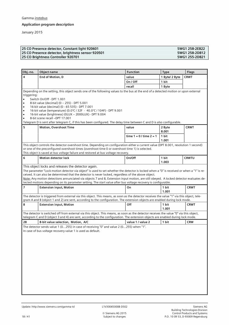
Obj.-no. Object name Function Type Flags
4 End of Motion, D value 1 Byte/ 2 Byte CRWT
On / Off 1 bit
recall 1 Byte
Depending on the setting, this object sends one of the following values to the bus at the end of a detected motion or upon externaltriggering:· Switch On/Off - DPT 1.001· 8-bit value (decimal) (0 – 255) - DPT 5.001· 16-bit value (decimal) (0 - 65 535) - DPT 7.001· 16-bit value (temperature) (0.0°C / 32F - 40.0°C / 104F) - DPT 9.001· 16-bit value (brightness) (0LUX – 2000LUX) - DPT 9.004· 8-bit scene recall –DPT 17.001Telegram D is sent after telegram C, if this has been configured. The delay time between C and D is also configurable.
5 Motion, Overshoot Time value 2 Byte8.001
CRWT
time 1 = 0 / time 2 = 1 1 bit1.001
This object controls the detector overshoot time. Depending on configuration either a current value (DPT 8.001, resolution 1 second)or one of the preconfigured overshoot times (overshoot time 0 or overshoot time 1) is selected.This object is saved at bus voltage failure and restored at bus voltage recovery.
6 Motion detector lock On/Off 1 bit1.003
CRWTU
This object locks and releases the detector again.The parameter “Lock motion detector via object” is used to set whether the detector is locked when a “0” is received or when a “1” is re-ceived. It can also be determined that the detector is never locked, regardless of the above object.Note: Any motion detections annunciated via objects 7 and 8, Extension input motion, are still obeyed. A locked detector evaluates de-tected motions depending on its parameter setting. The start value after bus voltage recovery is configurable.
7 Extension input, Motion On 1 bit1.001
CRWT
The detector is triggered from external via this object. This means, as soon as the detector receives the value “1” via this object, tele-gram A and B (object 1 and 2) are sent, according to the configuration. The extension objects are enabled during lock mode.
8 Extension input, Motion Off 1 bit1.001
CRWT
The detector is switched off from external via this object. This means, as soon as the detector receives the value “0” via this object,telegram C and D (object 3 and 4) are sent, according to the configuration. The extension objects are enabled during lock mode.
28 8-bit value selection, Motion, A/C value 1 / value 2 1 bit CRW
The detector sends value 1 (0...255) in case of receiving "0" and value 2 (0...255) when "1".In case of bus voltage recovery value 1 is used as default.

Gamma instabus
Application program description
January 2015
25 CO Presence detector, Constant light 920601 5WG1 258-2EB2225 CO Presence detector, brightness sensor 920501 5WG1258-2DB1225 CO Brightness Controller 920701 5WG1 255-2DB21
Siemens AG L1V30065000B-DS02 Update: http://www.siemens.com/gamma-tdBuilding Technologies DivisionControl Products and Systems ã Siemens AG 2015P.O. 10 09 53, D-93009 Regensburg Subject to changes 19 / 41
2.3.3 Communication objects presence detector
Obj.-no. Object name Function Type Flags
9 Start of Presence, A value 1 Byte/2 Byte
CRWT
On/Off 1 bit
recall 1 Byte
Depending on the setting, this object sends one of the following values to the bus at the beginning of a detected presence or on exter-nal triggering:· Switch On/Off - DPT 1.001· 8-bit value (decimal) (0 – 255) - DPT 5.001· 16-bit value (decimal) (0 - 65 535) - DPT 7.001· 16-bit value (temperature) (0.0°C / 32F - 40.0°C / 104F) - DPT 9.001· 16-bit value (brightness) (0LUX – 2000LUX) - DPT 9.004· 8-bit scene recall –DPT 17.001Note: After bus voltage recovery, there is a break of approximately 30 seconds before the detector can send via this object.
10 Start of Presence, B value 1 Byte/2 Byte
CRWT
On/Off 1 bit
recall 1 Byte
Depending on the setting, this object sends one of the following values to the bus at the beginning of a detected presence or on exter-nal triggering:· Switch On/Off - DPT 1.001· 8-bit value (decimal) (0 – 255) - DPT 5.001· 16-bit value (decimal) (0 - 65 535) - DPT 7.001· 16-bit value (temperature) (0.0°C / 32F - 40.0°C / 104F) - DPT 9.001· 16-bit value (brightness) (0LUX – 2000LUX) - DPT 9.004· 8-bit scene recall –DPT 17.001Telegram B is sent after telegram A, if this has been configured. The delay time between A and B is also configurable.
11 End of Presence, C value 1 Byte/2 Byte
CRWT
On/Off 1 bit
scene recall 1 Byte
Depending on the setting, this object sends one of the following values to the bus at the end of a detected presence or on externaltriggering:· Switch On/Off - DPT 1.001· 8-bit value (decimal) (0 – 255) - DPT 5.001· 16-bit value (decimal) (0 - 65 535) - DPT 7.001· 16-bit value (temperature) (0.0°C / 32F - 40.0°C / 104F) - DPT 9.001· 16-bit value (brightness) (0LUX – 2000LUX) - DPT 9.004· 8-bit scene recall –DPT 17.00112 End of Presence, D value 1 Byte/
2 ByteCRWT
On/Off 1 bit
recall 1 Byte
Depending on the setting, this object sends one of the following values to the bus at the end of a detected presence or on externaltriggering:· Switch On/Off - DPT 1.001· 8-bit value (decimal) (0 – 255) - DPT 5.001· 16-bit value (decimal) (0 - 65 535) - DPT 7.001· 16-bit value (temperature) (0.0°C / 32F - 40.0°C / 104F) - DPT 9.001· 16-bit value (brightness) (0LUX – 2000LUX) - DPT 9.004· 8-bit scene recall –DPT 17.001Telegram D is sent after telegram C, if this has been configured. The delay time between C and D is also configurable.

Gamma instabus
Application program description
January 2015
25 CO Presence detector, Constant light 920601 5WG1 258-2EB2225 CO Presence detector, brightness sensor 920501 5WG1 258-2DB1225 CO Brightness Controller 920701 5WG1 255-2DB21
Update: http://www.siemens.com/gamma-td L1V30065000B-DS02 Siemens AGBuilding Technologies Division
ã Siemens AG 2015 Control Products and Systems20 / 41 Subject to changes P.O. 10 09 53, D-93009 Regensburg
Obj.-no. Object name Function Type Flags
13 Presence, Overshoot Time value 2 Byte8.001
CRWT
time 1 = 0 / time 2 =1
1 bit1.001
This object controls the detector overshoot time. Depending on configuration either an actual value (DPT 8.001, resolution 1 second)or one of the preconfigured overshoot times (overshoot time 0 or overshoot time 1) is selected.This object is saved at bus voltage failure and restored at bus voltage recovery.
14 Presence lock On/Off 1 bit1.003
CRWTU
This object locks and releases the detector again.The parameter “Lock motion detector via object” is used to set whether the detector is locked when a “0” is received or when a “1” is re-ceived. It can also be determined that the detector is never locked, regardless of the above object.A locked detector evaluates detected motions depending on parameter settings.Note: Any presence detections annunciated via objects 15 and 16, Extension input motion, are still obeyed.The start value after bus voltage recovery is configurable.
15 Extension input,Presence
On 1 bit1.001
CRWT
The detector is triggered from external via this object. This means, as soon as the detector receives the value “1” via this object, tele-gram A and B (object 9 and 10) are sent, according to the configuration. The extension objects are enabled during lock mode.
16 Extension input,Presence
Off 1 bit1.001
CRWT
The detector is switched off from external via this object. This means, as soon as the detector receives the value “0” via this object,telegram C and D (object 11 and 12) are sent, according to the configuration. The extension objects are enabled during lock mode.
29 8-bit value selection, Presence, A/C value 1 / value 2 1 bit CRWThe detector sends value 1 (0...255) in case of receiving "0" and value 2 (0...255) when "1". The value will be sent immediately in caseof value C or D was sent as last value. In case of bus failure value 1 is used as default.
2.4 HVAC-Presence detector
2.4.1 Parameter
Parameter Settings
Lock HVAC sensor via comm.-object noYes, if locking object = 0Yes, if locking object = 1
This parameter determines how the value of the locking object is analyzed.
Interval time for HVAC-Presence detection(minutes)
0 – 15; 5
This parameter determines the time interval in which the motion pulses are counted.
Minimum number of detected motions during inter-val time
1 – 50; 3
This parameter determines the number of motions that have to be detected during the monitoring time to meet the criterion for start-ing the HVAC presence. This ensures that a HVAC presence starts only if persons remain in the capture area of the detector for a longerperiod.
Device works as single or master deviceslave
This parameter determines whether the detector is used as a standalone device or as a master or as a slave in conjunction with othermotion sensors.

Gamma instabus
Application program description
January 2015
25 CO Presence detector, Constant light 920601 5WG1 258-2EB2225 CO Presence detector, brightness sensor 920501 5WG1258-2DB1225 CO Brightness Controller 920701 5WG1 255-2DB21
Siemens AG L1V30065000B-DS02 Update: http://www.siemens.com/gamma-tdBuilding Technologies DivisionControl Products and Systems ã Siemens AG 2015P.O. 10 09 53, D-93009 Regensburg Subject to changes 21 / 41
2.4.1.1 Begin of HVAC PresenceThe following parameters are visible only if the device is working as a standalone device or as a master (parameter “Deviceworks as” is set to “Single or master device”).
Parameter Settings
If HVAC-Presence is detected, send (A) no telegramOnOff8-bit valuescene recall16-bit value (decimal)16-bit value (temperature)16-bit value (brightness)
This parameter determines whether a telegram is sent after a presence is detected and what format the telegram has.
Send second telegram (B) noyes
This parameter determines whether a second telegram is sent after a delay to the first.
Value [0 … 255] 0 - 255, 0
This parameter is visible only if the preceding parameter “If HVAC presence is detected, send (A)” is set to “8-bit value.”This sets the 8-bit value to be sent in the range 0 – 255.
Scene number scene 1, scene 2, … scene 64
This parameter is visible only if the preceding parameter “If HVAC presence is detected, send (A)” is set to “scene recall”.This parameter determines the number of the 8-bit scene to be called up.
Value [0 … 65535] 0 - 65535, 0
This parameter is visible only if the preceding parameter “If HVAC presence is detected, send (A)” is set to “16-bit value (decimal)”.This sets the 16-bit value to be sent in the range0 – 65535.
Value 0.0°C / 32F; 0.5°C / 32F; 1.0°C / 34F; 1.5°C /35F; … 16.5°C / 62F; … 39.5°C/103F; 40.0°C / 104F
This parameter is visible only if the preceding parameter “If HVAC presence is detected, send (A)” is set to “16-bit value (temperature)”.This sets the 16-bit value to be sent in the range0.0°C / 32F - 40.0°C / 104F.
Value 0LUX; 1LUX; 2LUX; 3LUX; 4LUX; 5LUX; 7LUX; 10LUX; 20LUX; 50LUX;100LUX; 150LUX; 200LUX; 250LUX; 300LUX; 350LUX; 400LUX; 450LUX;500LUX; 550LUX; 600LUX; 650LUX; 700LUX; 750LUX; 800LUX; 850LUX;900LUX; 950LUX; 1000LUX; 2000LUX
This parameter is visible only if the preceding parameter “If HVAC presence is detected, send (A)” is set to “16-bit value (brightness)”.This sets the 16-bit value to be sent in the range0 LUX - 2000 LUX .
Delay for second telegram[0 … 255 seconds]
0 - 255, 0
This parameter is visible only if the preceding parameter “Send second telegram (B)” is set to “Yes”.This determines the time interval between sending the first telegram (A) and the second telegram (B).
Second telegram (B) OnOff8-bit valuescene recall16-bit value (decimal)16-bit value (temperature)16-bit value (brightness)
This parameter is visible only if the preceding parameter “Send second telegram (B)” is set to “Yes”.This determines the format of the second telegram (B).

Gamma instabus
Application program description
January 2015
25 CO Presence detector, Constant light 920601 5WG1 258-2EB2225 CO Presence detector, brightness sensor 920501 5WG1 258-2DB1225 CO Brightness Controller 920701 5WG1 255-2DB21
Update: http://www.siemens.com/gamma-td L1V30065000B-DS02 Siemens AGBuilding Technologies Division
ã Siemens AG 2015 Control Products and Systems22 / 41 Subject to changes P.O. 10 09 53, D-93009 Regensburg
Parameter Settings
Value [0 … 255] 0 - 255, 0
This parameter is visible only if the preceding parameter “Second telegram (B)” is set to “8-bit value”.This sets the 8-bit value to be sent in the range 0 – 255.
Scene number Scene 1, scene 2, … scene 64
This parameter is visible only if the preceding parameter “Second telegram (B)” is set to “scene recall”.This parameter determines the number of the 8-bit scene to be called up.
Value [0 … 65535] 0 - 65535, 0
This parameter is visible only if the preceding parameter “Second telegram (B)” is set to “16-bit value (decimal)”.This sets the 16-bit value to be sent in the range 0 – 65535.
Value 0.0°C / 32F; 0.5°C / 32F; 1.0°C / 34F; 1.5°C /35F; … 16.5°C / 62F; … 39.5°C/103F; 40.0°C / 104F
This parameter is visible only if the preceding parameter “Second telegram (B)” is set to “16-bit value (temperature)”.This sets the 16-bit value to be sent in the range0.0°C / 32F - 40.0°C / 104F.
Value 0LUX; 1LUX; 2LUX; 3LUX; 4LUX; 5LUX; 7LUX; 10LUX; 20LUX; 50LUX;100LUX; 150LUX; 200LUX; 250LUX; 300LUX; 350LUX; 400LUX; 450LUX;500LUX; 550LUX; 600LUX; 650LUX; 700LUX; 750LUX; 800LUX; 850LUX;900LUX; 950LUX; 1000LUX; 2000LUX
This parameter is visible only if the preceding parameter “Second telegram (B)” is set to “16-bit value (brightness)”.This sets the 16-bit value to be sent in the range0 LUX - 2000 LUX .
Send second telegram (B) cyclically no1 second5 seconds10 seconds30 seconds1 minute
If you want cyclical sending after a motion is detected, then this parameter must be set to the corresponding value.
The following parameter is visible only if the device is working as a slave (parameter “Device works as” is set to “Slave”).
Parameter Settings
Send trigger telegrams cyclically no1 second5 seconds10 seconds30 seconds1 minute
A device in slave mode can only send an “On telegram” to the master if motion has been detected to trigger this via the secondary in-put. The internal overshoot time of 10 seconds is fixed, i.e. a telegram can be sent every 10 seconds to the master at most.If the slave detector is triggered permanently, then a telegram is sent to the master only on the first triggering. However, if the user inthis case wants to send further telegrams, then this can be achieved, but the above parameters must be set accordingly.

Gamma instabus
Application program description
January 2015
25 CO Presence detector, Constant light 920601 5WG1 258-2EB2225 CO Presence detector, brightness sensor 920501 5WG1258-2DB1225 CO Brightness Controller 920701 5WG1 255-2DB21
Siemens AG L1V30065000B-DS02 Update: http://www.siemens.com/gamma-tdBuilding Technologies DivisionControl Products and Systems ã Siemens AG 2015P.O. 10 09 53, D-93009 Regensburg Subject to changes 23 / 41
2.4.1.2 Versohlt timeThe following parameters are visible only if the device is working as a standalone device or as a master (parameter “Deviceworks as” is set to “Single or master device”).
Parameter Settings
Timer one overshoot timetwo overshoot timesvariable overshoot time
This parameter determines whether the overshoot time is always the same (“One overshoot time”) or can be changed via a bus tele-gram (object no. 21).If “Two overshoot times” are set, then overshoot time 0 or overshoot time 1 can be selected via the telegram. If the “Timer” parameteris set to “variable overshoot times,” then the telegram can stipulate a value.
Hours [0 … 23] 0 – 23, 0
Minutes [0 … 59] 0 – 59, 0
Seconds [0 … 59] 0 – 59, 10
These parameters determine the minimum time for a detected HVAC presence. At the end of the overshoot time, one or two telegramsare sent on the bus (configurable). If a HVAC presence has already been detected (overshoot time running) and further motion occurs,then the overshoot time is restarted.If the “Timer” parameter described above is set to “Two overshoot times,” then these parameters are available twice (overshoot time 0and overshoot time 1).
2.4.1.3 End of HVAC PresenceThe following parameters are visible only if the device is working as a standalone device or as a master (parameter “Deviceworks as” is set to “Single or master device”).
Parameter Settings
If HVAC-Presence is no longer detected, send (C) no telegramOnOff8-bit valuescene recall16-bit value (decimal)16-bit value (temperature)16-bit value (brightness)
This parameter determines whether a telegram or which telegram is sent, if no further HVAC presence has been detected by the end ofthe overshoot time.
Send second telegram (D) noyes
This parameter determines whether a second telegram is sent after a delay to the first.
Value [0 … 255] 0 - 255, 0
This parameter is visible only if the preceding parameter “If HVAC presence is no longer detected, send (C)” is set to “8-bit value”.This sets the 8-bit value to be sent in the range 0 – 255.
Scene number Scene 1, scene 2, … scene 64
This parameter is visible only if the preceding parameter “If HVAC presence is no longer detected, send (C)” is set to “scene recall”.This parameter determines the number of the 8-bit scene to be called up.
Value [0 … 65535] 0 - 65535, 0
This parameter is visible only if the preceding parameter “If HVAC presence is no longer detected, send (C)” is set to “16-bit value (dec-imal)”.This sets the 16-bit value to be sent in the range 0 – 65535.

Gamma instabus
Application program description
January 2015
25 CO Presence detector, Constant light 920601 5WG1 258-2EB2225 CO Presence detector, brightness sensor 920501 5WG1 258-2DB1225 CO Brightness Controller 920701 5WG1 255-2DB21
Update: http://www.siemens.com/gamma-td L1V30065000B-DS02 Siemens AGBuilding Technologies Division
ã Siemens AG 2015 Control Products and Systems24 / 41 Subject to changes P.O. 10 09 53, D-93009 Regensburg
Parameter Settings
Value 0.0°C / 32F; 0.5°C / 32F; 1.0°C / 34F; 1.5°C /35F; … 16.5°C / 62F; … 39.5°C/103F; 40.0°C / 104F
This parameter is visible only if the preceding parameter “If HVAC presence is no longer detected, send (C)” is set to “16-bit value (tem-perature)”.This sets the 16-bit value to be sent in the range0.0°C / 32F - 40.0°C / 104F.
Value 0LUX; 1LUX; 2LUX; 3LUX; 4LUX; 5LUX; 7LUX; 10LUX; 20LUX; 50LUX;100LUX; 150LUX; 200LUX; 250LUX; 300LUX; 350LUX; 400LUX; 450LUX;500LUX; 550LUX; 600LUX; 650LUX; 700LUX; 750LUX; 800LUX; 850LUX;900LUX; 950LUX; 1000LUX; 2000LUX
This parameter is visible only if the preceding parameter “If HVAC presence is no longer detected, send (C)” is set to “16-bit value(brightness)”. This sets the 16-bit value to be sent in the range 0 LUX - 2000 LUX .
Delay for second telegram[0 … 255 Seconds]
0 - 255, 0
This parameter is visible only if the preceding parameter “Send second telegram (D)” is set to “Yes.”This determines the time interval between sending the first telegram (C) and the second telegram (D).
Second Telegramm (D) OnOff8-bit valuescene recall16-bit value (decimal)16-bit value (temperature)16-bit value (brightness)
This parameter is visible only if the preceding parameter “Send second telegram (D)” is set to “Yes”.This determines the format of the second telegram (D).
Value [0 … 255] 0 - 255, 0
This parameter is visible only if the preceding parameter “Second telegram (D)” is set to “8-bit value”.This sets the 8-bit value to be sent in the range 0 – 255.
Scene number Scene 1, scene 2, … scene 64
This parameter is visible only if the preceding parameter “Second telegram (D)” is set to “scene recall”.This parameter determines the number of the 8-bit scene to be called up.
Value [0 … 65535] 0 - 65535, 0
This parameter is visible only if the preceding parameter “Second telegram (D)” is set to “16-bit value (decimal)”.This sets the 16-bit value to be sent in the range0 – 65535.
Value 0.0°C / 32F; 0.5°C / 32F; 1.0°C / 34F; 1.5°C /35F; … 16.5°C / 62F; … 39.5°C/103F; 40.0°C / 104F
This parameter is visible only if the preceding parameter “Second telegram (D)” is set to “16-bit value (temperature)”.This sets the 16-bit value to be sent in the range 0.0°C / 32F - 40.0°C / 104F.
Value 0LUX; 1LUX; 2LUX; 3LUX; 4LUX; 5LUX; 7LUX; 10LUX; 20LUX; 50LUX;100LUX; 150LUX; 200LUX; 250LUX; 300LUX; 350LUX; 400LUX; 450LUX;500LUX; 550LUX; 600LUX; 650LUX; 700LUX; 750LUX; 800LUX; 850LUX;900LUX; 950LUX; 1000LUX; 2000LUX
This parameter is visible only if the preceding parameter “Second telegram (D)” is set to “16-bit value (brightness)”.This sets the 16-bit value to be sent in the range 0 LUX - 2000 LUX .
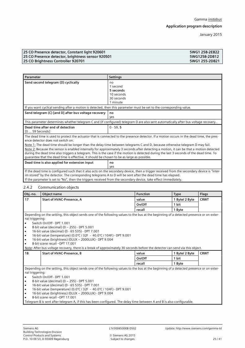
Gamma instabus
Application program description
January 2015
25 CO Presence detector, Constant light 920601 5WG1 258-2EB2225 CO Presence detector, brightness sensor 920501 5WG1258-2DB1225 CO Brightness Controller 920701 5WG1 255-2DB21
Siemens AG L1V30065000B-DS02 Update: http://www.siemens.com/gamma-tdBuilding Technologies DivisionControl Products and Systems ã Siemens AG 2015P.O. 10 09 53, D-93009 Regensburg Subject to changes 25 / 41
Parameter Settings
Send second telegram (D) cyclically no1 second5 seconds10 seconds30 seconds1 minute
If you want cyclical sending after a motion is detected, then this parameter must be set to the corresponding value.
Send telegram (C) [and D] after bus voltage recovery noyes
This parameter determines whether telegram C and (if configured) telegram D are also sent automatically after bus voltage recovery..
Dead time after end of detection[0 … 59 Seconds]
0 - 59, 5
The dead time is used to protect the actuator that is connected to the presence detector. If a motion occurs in the dead time, the pres-ence detector does not switch on.Note 1: The dead time should be longer than the delay time between telegrams C and D, because otherwise telegram D may fail.Note 2: Because the sensor is enabled internally for approximately 3 seconds after detecting a motion, it can be that a motion detectedduring the dead time also triggers a telegram. This is the case if the motion is detected during the last 3 seconds of the dead time. Toguarantee that the dead time is effective, it should be chosen to be as large as possible.
Dead time is also applied for extension input noyes
If the dead time is configured such that it also acts on the secondary device, then a trigger received from the secondary device is “inter-im stored” by the detector. The corresponding telegrams A to D will be sent after the dead time has elapsed.If the parameter is set to “No”, then the triggers received from the secondary device, take effect immediately.
2.4.2 Communication objects
Obj.-no. Object name Function Type Flags
17 Start of HVAC-Presence, A value 1 Byte/ 2 Byte CRWT
On/Off 1 bit
recall 1 Byte
Depending on the setting, this object sends one of the following values to the bus at the beginning of a detected presence or on exter-nal triggering:· Switch On/Off - DPT 1.001· 8-bit value (decimal) (0 – 255) - DPT 5.001· 16-bit value (decimal) (0 - 65 535) - DPT 7.001· 16-bit value (temperature) (0.0°C / 32F - 40.0°C / 104F) - DPT 9.001· 16-bit value (brightness) (0LUX – 2000LUX) - DPT 9.004· 8-bit scene recall –DPT 17.001Note: After bus voltage recovery, there is a break of approximately 30 seconds before the detector can send via this object.
18 Start of HVAC-Presence, B value 1 Byte/ 2 Byte CRWT
On/Off 1 bit
recall 1 Byte
Depending on the setting, this object sends one of the following values to the bus at the beginning of a detected presence or on exter-nal triggering:· Switch On/Off - DPT 1.001· 8-bit value (decimal) (0 – 255) - DPT 5.001· 16-bit value (decimal) (0 - 65 535) - DPT 7.001· 16-bit value (temperature) (0.0°C / 32F - 40.0°C / 104F) - DPT 9.001· 16-bit value (brightness) (0LUX – 2000LUX) - DPT 9.004· 8-bit scene recall –DPT 17.001Telegram B is sent after telegram A, if this has been configured. The delay time between A and B is also configurable.

Gamma instabus
Application program description
January 2015
25 CO Presence detector, Constant light 920601 5WG1 258-2EB2225 CO Presence detector, brightness sensor 920501 5WG1 258-2DB1225 CO Brightness Controller 920701 5WG1 255-2DB21
Update: http://www.siemens.com/gamma-td L1V30065000B-DS02 Siemens AGBuilding Technologies Division
ã Siemens AG 2015 Control Products and Systems26 / 41 Subject to changes P.O. 10 09 53, D-93009 Regensburg
Obj.-no. Object name Function Type Flags
19 End of HVAC-Presence, C value 1 Byte/ 2 Byte CRWT
On/Off 1 bit
recall 1 Byte
Depending on the setting, this object sends one of the following values to the bus at the end of a detected presence or on externaltriggering:· Switch On/Off - DPT 1.001· 8-bit value (decimal) (0 – 255) - DPT 5.001· 16-bit value (decimal) (0 - 65 535) - DPT 7.001· 16-bit value (temperature) (0.0°C / 32F - 40.0°C / 104F) - DPT 9.001· 16-bit value (brightness) (0LUX – 2000LUX) - DPT 9.004· 8-bit scene recall –DPT 17.001
20 End of HVAC-Presence, D value 1 Byte/ 2 Byte CRWT
On/Off 1 bit
recall 1 Byte
Depending on the setting, this object sends one of the following values to the bus at the end of a detected presence or on externaltriggering:· Switch On/Off - DPT 1.001· 8-bit value (decimal) (0 – 255) - DPT 5.001· 16-bit value (decimal) (0 - 65 535) - DPT 7.001· 16-bit value (temperature) (0.0°C / 32F - 40.0°C / 104F) - DPT 9.001· 16-bit value (brightness) (0LUX – 2000LUX) - DPT 9.004· 8-bit scene recall –DPT 17.001Telegram D is sent after telegram C, if this has been configured. The delay time between C and D is also configurable.
21 HVAC-Presence, overshoot time value 2 Byte8.001
CRWT
Off = 1 On = 2 1 bit1.001
This object controls the detector overshoot time. Depending on configuration either an actual value (DPT 8.001, resolution 1 second)or one of the preconfigured overshoot times (overshoot time 0 or overshoot time 1) is selected.This object is saved at bus voltage failure and restored at bus voltage recovery.
22 HVAC-Presence lock On/Off 1 bit1.003
CRWTU
This object locks and releases the detector again.The parameter “Lock motion detector via object” is used to set whether the detector is locked when a “0” is received or when a “1” is re-ceived. It can also be determined that the detector is never locked, regardless of the above object.Note: Any HVAC-presence detections annunciated via objects 23 and 24, Extension input motion, are still obeyed.A locked detector does not evaluate detected motions.The start value after bus voltage recovery is configurable.
23 Extension input, HVAC-Presence On 1 bit1.001
CRWT
The detector is triggered from external via this object. This means, as soon as the detector receives the value “1” via this object, tele-gram A and B (object 17 and 18) are sent, according to the configuration.
24 Extension input, HVAC-Presence Off 1 bit1.001
CRWT
The detector is switched off from external via this object. This means, as soon as the detector receives the value “0” via this object,telegram C and D (object 19 and 20) are sent, according to the configuration.

Gamma instabus
Application program description
January 2015
25 CO Presence detector, Constant light 920601 5WG1 258-2EB2225 CO Presence detector, brightness sensor 920501 5WG1258-2DB1225 CO Brightness Controller 920701 5WG1 255-2DB21
Siemens AG L1V30065000B-DS02 Update: http://www.siemens.com/gamma-tdBuilding Technologies DivisionControl Products and Systems ã Siemens AG 2015P.O. 10 09 53, D-93009 Regensburg Subject to changes 27 / 41
2.5 2-level light controller (on-off)
2.5.1 Parameter
Parameter Settings
Source for brightness value (actual value) internal valueexternal value
This parameter selects the source for the brightness value.
Setpoint value via parameterparameter changeable via object
This parameter determines whether the setpoint for light control are set to a fixed value, which in each case can be changed only usingthe ETS, or whether the corresponding factory-provided values can be changed via the bus, via a communication object.The value received via the communication object overwrites the factory-provided parameter value and is stored permanently.
2.5.1.1 Switch-OnParameter Settings
Switch on, if brightness is lower than xx LUX 100 – 1600, 500
This parameter determines the starting brightness value from which the “Switching on” telegram (object no. 51) will be sent.If the brightness value for switching on is greater than the brightness value for switching off, then the value for switching on will be setby the controller to the value for switching off, i.e. both values are then identical. This means that the controller only has to send a tel-egram to switch on. Switching off in this case is a manual process.Note 1: The internal light sensor has a measurement range from 20 to 1000 LUX. It is therefore sensible to set a threshold above 1000LUX only if an external sensor, having a corresponding measurement range, is used for brightness measurement, or indirect measure-ment has been configured.Note 2: Depending on the internal recalculation of the value, this can cause impreciseness when resolving of approximately 5%.
Switch on, not before xx seconds. 0 - 59, 10
This parameter determines the interval at which the corresponding telegram for switching on is sent after falling below the nominalbrightness value.
2.5.1.2 Switch-OffParameter Settings
Switch off, if brightness is higher than xx LUX 250 - 1600, 900
This parameter determines the starting brightness value from which the “Switching off” telegram (object no. 52) will be sent.Note 1: The internal light sensor has a measurement range from 20 to 1000 LUX. It is therefore sensible to set a threshold above 1000LUX only if an external sensor, having a corresponding measurement range, is used for brightness measurement, or indirect measure-ment has been configured.Note 2: Depending on the internal recalculation of the value, this can cause impreciseness when resolving of approximately 5%.
Switch off, not before xx seconds. 0 -59, 20
This parameter determines the interval at which the corresponding telegram for switching off is sent after exceeding the nominalbrightness value.

Gamma instabus
Application program description
January 2015
25 CO Presence detector, Constant light 920601 5WG1 258-2EB2225 CO Presence detector, brightness sensor 920501 5WG1 258-2DB1225 CO Brightness Controller 920701 5WG1 255-2DB21
Update: http://www.siemens.com/gamma-td L1V30065000B-DS02 Siemens AGBuilding Technologies Division
ã Siemens AG 2015 Control Products and Systems28 / 41 Subject to changes P.O. 10 09 53, D-93009 Regensburg
2.5.2 Communication objects
Obj.-no. Object name Function Type Flags
44 Control unit On/Off (on-off) On/Off 1 bit1.001
CWT
This object switches the controller on or off per group address. This information can come from a bus button or from the output objectof a presence detector, for example.
45 Automatic mode (on-off) On/Off 1 bit CWT
The controller notifies its internal status to the outside world via this object. The status can either have the value “On,” i.e. the control-ler works in automatic mode, or the value “Off.” Moreover, this does not differentiate between whether the controller was switched offmanually or by override.Describing this object has no effect.
46 Setpoint for switching on value in LUX 2 Byte9.004
CRW
This object notifies the brightness controller of the setpoint for switching on in automatic mode. Until the first occurrence of a value,the value from the parameter “Switch on if brightness value less than xx LUX” is used as the setpoint.This object is saved at bus voltage failure and restored at bus voltage recovery.
47 Setpoint for switching off value in LUX 2 Byte9.004
CRW
This object notifies the brightness controller of the setpoint for switching off in automatic mode. Until the first occurrence of a value,the value from the parameter “Switch off if brightness value greater than xx LUX” is used as the setpoint.This object is saved at bus voltage failure and restored at bus voltage recovery.
48 Input switching value (on-off) On/Off 1 bit1.001
CWT
If a value (logical 0 or 1) is received via this object, the controller switches off (automatic mode off), because it has been overwrittenfrom outside.Only by receiving “logical 1” via object no. 44 will the controller be switched on again (automatic mode on).
49 Input dimming value (on-off) brighter / darker 4 bit3.007
CWT
If a value is received via this object, the controller switches off, because it has been overwritten from outside.Only by receiving “logical 1” via object no. 44 will the controller be switched on again (automatic mode on).
50 Input dimming value (on-off) value 1 Byte5.001
CWT
If a value (0-255) is received via this object, the controller switches off, because it has been overwritten from outside.Only by receiving “logical 1” via object no. 44 will the controller be switched on again (automatic mode on).
51 Switching (on-off) On 1 bit1.001
CWT
This object is one of the outputs of the two-point controller. It sends the value “On” if the brightness is below the defined brightnessvalue in a given period of time.
52 Switching (on-off) Off 1 bit1.001
CWT
This object is one of the outputs of the two-point controller. It sends the value “Off” if the brightness is below the defined brightnessvalue in a given period of time.
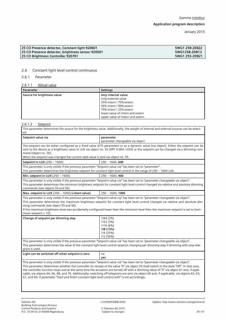
Gamma instabus
Application program description
January 2015
25 CO Presence detector, Constant light 920601 5WG1 258-2EB2225 CO Presence detector, brightness sensor 920501 5WG1258-2DB1225 CO Brightness Controller 920701 5WG1 255-2DB21
Siemens AG L1V30065000B-DS02 Update: http://www.siemens.com/gamma-tdBuilding Technologies DivisionControl Products and Systems ã Siemens AG 2015P.O. 10 09 53, D-93009 Regensburg Subject to changes 29 / 41
2.6 Constant light level control continuous
2.6.1 Parameter
2.6.1.1 Aktual valueParameter Settings
Source for brightness value only internal valueonly external value25% intern / 75% extern50% intern / 50% extern75% intern / 25% externlower value of intern and externupper value of intern und extern
2.6.1.2 SetpointThis parameter determines the source for the brightness value. Additionally, the weight of internal and external sources can be select-ed.
Setpoint value via parameterparameter changeable via object
The setpoint can be either configured as a fixed value (ETS parameter) or as a dynamic value (via object). Either the setpoint can besent to the device as a brightness value in LUX via object no. 55 (DPT 9.004 / EIS5) or the setpoint can be changed via a dimming com-mand (object no. 56).When the setpoint was changed the current valid value is sent via object no. 55.
Setpoint in LUX [250 – 1600] 250 - 1600, 600
This parameter is only visible if the previous parameter “Setpoint value via” has been set to “parameter”.This parameter determines the brightness setpoint for constant light level control in the range of 250 – 1600 LUX.
Min. setpoint in LUX [250 – 1600] 250 - 1600, 400
This parameter is only visible if the previous parameter “Setpoint value via” has been set to “parameter changeable via object”.This parameter determines the minimum brightness setpoint for constant light level control changed via relative and absolute dimmingcommands (see objects 55 and 56).
Max. setpoint in LUX [250 – 1600] (=Start value) 250 - 1600, 1000
This parameter is only visible if the previous parameter “Setpoint value via” has been set to “parameter changeable via object”.This parameter determines the maximum brightness setpoint for constant light level control changed via relative and absolute dim-ming commands (see object 55 and 56).If the maximum brightness level was accidentally configured lower than the minimum level then the maximum setpoint is set to [min-imum setpoint + 10].
Change of setpoint per dimming step 1/64 (2%)1/32 (3%)1/16 (6%)1/8 (13%)1/4 (25%)1/2 (50%)
This parameter is only visible if the previous parameter “Setpoint value via” has been set to “parameter changeable via object”.This parameter determines the value of the constant light level control setpoint changing per dimming step if dimming with stop tele-gram is used.
Light can be switched off when setpoint is zero noyes
This parameter is only visible if the previous parameter “Setpoint value via” has been set to “parameter changeable via object”.This parameter determines whether the controller on receipt of the value “0” via object 55 shall switch to the state “Off”. In that case,the controller function stops and at the same time the actuators are turned off with a dimming value of “0” via object 61 and, if appli-cable, via objects 64, 66, 68, and 70. Additionally, switching off telegrams are sent via object 60 and, if applicable, via objects 63, 65,67, and 69, if parameter “Start and finish constant light level control with” is set accordingly.

Gamma instabus
Application program description
January 2015
25 CO Presence detector, Constant light 920601 5WG1 258-2EB2225 CO Presence detector, brightness sensor 920501 5WG1 258-2DB1225 CO Brightness Controller 920701 5WG1 255-2DB21
Update: http://www.siemens.com/gamma-td L1V30065000B-DS02 Siemens AGBuilding Technologies Division
ã Siemens AG 2015 Control Products and Systems30 / 41 Subject to changes P.O. 10 09 53, D-93009 Regensburg
Parameter Settings
Control can be started when setpoint is greater thanzero
noyes
This parameter is only visible if the previous parameter “Setpoint value via” has been set to “parameter changeable via object”.This parameter determines whether the controller switches from the state “inactive” to the state “active” if a setpoint value greater than“0” is received via object 55.At the same time the received LUX value is the new set point.
2.6.1.3 ControllerParameter Settings
Maximal deviation from setpoint value (hysteresis) +/- 5%+/- 10%+/- 15%+/- 20%
This parameter determines the difference between current value and setpoint value that activates the controller.This parameter only affects the control of the main lighting group.
Send dimming value every (controller speed) 1 second2 seconds3 seconds5 seconds10 seconds20 seconds
This parameter determines the interval for sending the calculated control values.Note: When an external measurement is used then setting the parameter to 1 second makes sense, assuming that the external value isreceived within half of the time selected here. When the internal measurement is used this parameter should be set to a value that is atleast double the value of the parameter setting of “Number of values for calculation of average”.
Timeout for automatic off [min](0 = no automatic off)
0 – 230, 3
If the actuating variable of the controller in the “active” state has reached the configured minimum level and at the same time the cur-rent value of the measured brightness is higher than the brightness setpoint, then the controller changes into the state “standby” andsends a switching telegram with the value “Off”.The period from reaching the condition described above to switching into the state “standby” is determined by the previous parameterin the range 1-255 minutes. If that parameter is set to “0” then the controller remains in the state “active” with the minimum controlvalues.
Additional hysteresis for restart when controller wasin standby[LUX]
0 – 230, 100
When the controller is in the state “standby” and the current light level value drops below the setpoint value minus hysteresis minusadditional hysteresis then the controller automatically changes into the state “active”.Note: If setpoint value minus hysteresis minus additional hysteresis is lower than 50 LUX, then 50 LUX is used as the limit for changingback to the state “active”.
Start and finish constant light level control with only dimming-value telegramadditional switching telegram at begin of controladditional switching telegram at stop of controladditional switching telegram at begin and stop
This parameter determines the type of telegrams sent by the constant light level controller on start and ending of the control activity(switching into state “active” respectively leaving the “active” state).
2.6.1.4 Controller outputParameter Settings
Max. step for dimming 1 (0,5%); 3 (1,1%); 4 (1,5%);5 (2,0%); 6 (2,5%), 7 (2,7%);10 (3,9%)
This parameter determines the maximum step of the control value to be used for dimming.Note: The maximum step for dimming should be chosen such that a change of the dimming value does not change the illuminationmore than the configured hysteresis of the set point.

Gamma instabus
Application program description
January 2015
25 CO Presence detector, Constant light 920601 5WG1 258-2EB2225 CO Presence detector, brightness sensor 920501 5WG1258-2DB1225 CO Brightness Controller 920701 5WG1 255-2DB21
Siemens AG L1V30065000B-DS02 Update: http://www.siemens.com/gamma-tdBuilding Technologies DivisionControl Products and Systems ã Siemens AG 2015P.O. 10 09 53, D-93009 Regensburg Subject to changes 31 / 41
Parameter Settings
First dim-value, when control starts copy from parameterquery from actuator’s statuscalculate start value
This parameter determines how the first dimming value (starting value) for the control is established.query from actuator’s status (default setting):The current control value of the dimming actuator is interrogated via a status read request and the control loop is started with this val-ue. This action takes into account that the dimming value could have been changed by a relative dimming command while the controlloop was inactive. The status read request does not work with all DALI Gateways.calculate start value:Before the control starts the current actual value is measured. This value represents the mixed light (daylight and artificial light). Usingthe calibration curve the measured value of the room brightness is then computed into the control value, which is used as a startingvalue for the control.copy from parameter:This parameter setting is used if the other two options do not apply.
Max. dimming value Master [1 … 255] 1 – 255, 255
This parameter determines the maximum dimming value of the master.
Min. dimming value Master [1 … 255] 1 – 255, 1
This parameter determines the minimum dimming value of the master.
Master / slave operation noyes
This parameter determines whether the controller runs in master/slave operation or not.
First dim value[1 … 255]
1 – 255, 128
This parameter is only visible if the parameter “First dim-value when control starts” is set to “copy from parameter”.This parameter determines the starting value used by the controller for the control value.
First dim-value when, reading from object fails[1…255]
1 – 255, 128
This parameter is only visible if the parameter “First dim value when control starts” is set to “query from actuator’s status”.This parameter determines the starting value used by the controller for the control value if the status query of the dimming actuatordoes not return a value within one second.
2.6.1.5 SlavesThe following parameters are only visible if the parameter “master/slave operation” has been set to “Yes”.
Parameter Settings
Mode of calculation calculating via characteristiccalculating via offsets
This parameter determines how the control value for the additional lighting groups is calculated.calculating via characteristic: The control values for the additional lighting groups are derived from the main control value by calibra-tion curves transforming the measured (main) luminance level into a calculated luminance level for the position of each additionallighting groups. If this setting is selected parameter settings in 3.6.6-a apply.calculating via offset: The control values for the additional lighting groups are derived from the main control value by an offset that isentered for each additional lighting group. If this setting is selected parameter settings in 3.6.6-b apply.
Number of slaves 1 – 4, 4
This parameter determines the number of additional lighting control groups.
Max. dimming value slave 1 [2, 3, 4][1 … 255]
1 – 255, 255
This parameter determines the maximum dimming value of the respective additional lighting control group (1…4).

Gamma instabus
Application program description
January 2015
25 CO Presence detector, Constant light 920601 5WG1 258-2EB2225 CO Presence detector, brightness sensor 920501 5WG1 258-2DB1225 CO Brightness Controller 920701 5WG1 255-2DB21
Update: http://www.siemens.com/gamma-td L1V30065000B-DS02 Siemens AGBuilding Technologies Division
ã Siemens AG 2015 Control Products and Systems32 / 41 Subject to changes P.O. 10 09 53, D-93009 Regensburg
Parameter Settings
Min. dimming value slave 1 [2, 3, 4][1 … 255]
1 – 255, 1
This parameter determines the minimum dimming value of the respective additional lighting control group (1…4).
2.6.1.5.1 Slave offset dataThe following parameters are only visible if the parameter “master/slave operation” has been set to “Yes” and the parame-ter “Mode of calculation” has been set to “calculation via offsets”.
Parameter Settings
Offset for slave 1 to the master dimming value in percent (-100…100) 0 (-100…100)
This parameter determines the offset used to calculate the dimming value for slave 1 from the dimming value of the master.Note: The limits for the minimum and maximum control values apply.
Offset for slave 2 to the master dimming value in percent (-100…100) 0 (-100…100)
This parameter determines the offset used to calculate the dimming value for slave 2 from the dimming value of the master.Note: The limits for the minimum and maximum control values apply.
Offset for slave 3 to the master dimming value in percent (-100…100) 0 (-100…100)
This parameter determines the offset used to calculate the dimming value for slave 3 from the dimming value of the master.Note: The limits for the minimum and maximum control values apply.
Offset for slave 4 to the master dimming value in percent (-100…100) 0 (-100…100)
This parameter determines the offset used to calculate the dimming value for slave 4 from the dimming value of the master.Note: The limits for the minimum and maximum control values apply.
2.6.1.5.2 Slave calibration dataThe following parameters are only visible if the parameter “master/slave operation” has been set to “Yes” and the parame-ter “Mode of calculation” has been set to “calculation via characteristic”.
Parameter Settings
Position of Master[A … E]
at measuring position Aat measuring position Bat measuring position Cat measuring position Dat measuring position E
This parameter determines the position (A…E) of the main lighting control group. The number of positions depends on the number ofadditional lighting control groups (slaves) selected via the parameter “number of slaves”. If e.g. the “number of slaves” was set to “2”then the positions A…C are available.
Measured LUX value at position A [0…2000] 0 – 2000, 0
Enter the illumination value measured at lighting position A with an luminance (LUX) meter in the range of 0…2000 LUX.
Measured LUX value at position B [0…2000] 0 – 2000, 0
Enter the illumination value measured at lighting position B with an luminance (LUX) meter in the range of 0…2000 LUX.
Measured LUX value at position C [0…2000] 0 – 2000, 0
This parameter is only visible if the parameter “number of slaves” has been set to “2”, “3” or “4”.Enter the illumination value measured at lighting position C with an luminance (LUX) meter in the range of 0…2000 LUX.
Measured LUX value at position D [0…2000] 0 – 2000, 0
This parameter is only visible if the parameter “number of slaves” has been set to “3” or “4”.Enter the illumination value measured at lighting position D with an luminance (LUX) meter in the range of 0…2000 LUX.
Measured LUX value at position E [0…2000] 0 – 2000, 0
This parameter is only visible if the parameter “number of slaves” has been set to “4”.Enter the illumination value measured at lighting position E with an luminance (LUX) meter in the range of 0…2000 LUX.

Gamma instabus
Application program description
January 2015
25 CO Presence detector, Constant light 920601 5WG1 258-2EB2225 CO Presence detector, brightness sensor 920501 5WG1258-2DB1225 CO Brightness Controller 920701 5WG1 255-2DB21
Siemens AG L1V30065000B-DS02 Update: http://www.siemens.com/gamma-tdBuilding Technologies DivisionControl Products and Systems ã Siemens AG 2015P.O. 10 09 53, D-93009 Regensburg Subject to changes 33 / 41
2.6.1.6 Control characteristic
Parameter Settings
Delay until next step 10 - 60, 12
This parameter determines the period (range: 10 to 60 seconds) between each of the brightness measurements of the controller dur-ing calibration (compare object 71).Note: Select a higher value for lamps with a longer warm up phase until providing full light output.
2.6.2 Communication objects
Obj.-no. Object name Function Type Flags
43 Control actual value (continuous) value in LUX 2 Byte9.004
CRW
Via the group address assigned to this object the current control actual value in LUX is transmitted on a read request.Note: Set the Transmit (T) flag for sending on change of value.
53 Control unit On/Off (continuous) On / Off 1 bit1.001
CWT
The constant light level controller can be switched on or off via a group address assigned to this object. This command may come froma wall switch or an output object of a presence detector.When a logical ”0” is received the controller is turned off, i.e. set point value and actual value are no longer compared. Thus the con-stant light level control is stopped. When the controller is turned off the control value 0 is sent.When a logical “1” is received the controller is turned on.On bus voltage recovery the controller is turned off, independent of the status the controller had before bus voltage failure.
54 Status, Automatic mode (continuous) On / Off 1 bit CRT
The controller communicates its internal state via this object. When the state „On“ is communicated the controller is either in the state“active” or “standby”. When the state “Off” is communicated then the controller is either in the state “inactive” or “off”.Writing to this object has no effect.
55 Setpoint abs. (DPT 9.004) (continuous) value in LUX 2 Byte9.004
CRWT
Via this object the setpoint for the constant light level control is set. Until the first value is received the value of the parameter “Maxi-mum setpoint in LUX” is used as default value.Note 1: The currently valid control setpoint is sent via this object onto the bus on change of value, thus allowing a visualization to dis-play the current value.Note 2: When the setpoint value changes the control process may be active dependent on the determined calibration curve even if theactual value is within the range defined by the setpoint and the hysteresis.Note 3: On bus voltage recovery the value of this object is sent automatically.Note 4: The setpoint value is limited by the configuration settings for minimum / maximum set point value.Note 5: On reception of 0 the set point value is not changed.
56 Setpoint rel. (DPT 3007) (continuous) brighter / darker 4 bit3.007
CRW
Via this object the setpoint can be changed relative to the current value. The controller increments or decrements the internal setpointevery second by a dimming value set via parameter, if “dimming with stop telegram” is used.Note1: The controller can process relative changes of the setpoint only every second. When e.g. two ¼-brighter dimming telegrams arereceived within 200ms then both are joined together. The result is one dimming brighter command with about 56% increase.Note 2: The setpoint value is limited by the configuration settings for minimum / maximum set point value.
57 Control stop, switching value (continuous) On / Off 1 bit1.001
CWT
When a value is received via this object then the controller changes its state to ”inactive”. In this state the controller is passive, i.e. nocontrol commands are sent onto the bus.
58 Control stop, dimming (continuous) brighter / darker 4 bit3.007
CWTU
When a value is received via this object then the controller changes its state to ”inactive”. In this state the controller is passive, i.e. nocontrol commands are sent onto the bus.
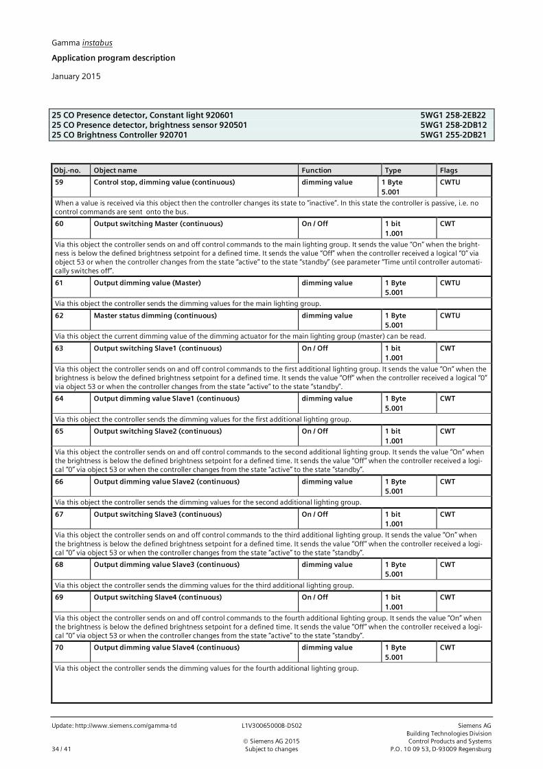
Gamma instabus
Application program description
January 2015
25 CO Presence detector, Constant light 920601 5WG1 258-2EB2225 CO Presence detector, brightness sensor 920501 5WG1 258-2DB1225 CO Brightness Controller 920701 5WG1 255-2DB21
Update: http://www.siemens.com/gamma-td L1V30065000B-DS02 Siemens AGBuilding Technologies Division
ã Siemens AG 2015 Control Products and Systems34 / 41 Subject to changes P.O. 10 09 53, D-93009 Regensburg
Obj.-no. Object name Function Type Flags
59 Control stop, dimming value (continuous) dimming value 1 Byte5.001
CWTU
When a value is received via this object then the controller changes its state to ”inactive”. In this state the controller is passive, i.e. nocontrol commands are sent onto the bus.
60 Output switching Master (continuous) On / Off 1 bit1.001
CWT
Via this object the controller sends on and off control commands to the main lighting group. It sends the value “On” when the bright-ness is below the defined brightness setpoint for a defined time. It sends the value “Off” when the controller received a logical “0” viaobject 53 or when the controller changes from the state “active” to the state “standby” (see parameter “Time until controller automati-cally switches off”.
61 Output dimming value (Master) dimming value 1 Byte5.001
CWTU
Via this object the controller sends the dimming values for the main lighting group.
62 Master status dimming (continuous) dimming value 1 Byte5.001
CWTU
Via this object the current dimming value of the dimming actuator for the main lighting group (master) can be read.
63 Output switching Slave1 (continuous) On / Off 1 bit1.001
CWT
Via this object the controller sends on and off control commands to the first additional lighting group. It sends the value “On” when thebrightness is below the defined brightness setpoint for a defined time. It sends the value “Off” when the controller received a logical “0”via object 53 or when the controller changes from the state “active” to the state “standby”.
64 Output dimming value Slave1 (continuous) dimming value 1 Byte5.001
CWT
Via this object the controller sends the dimming values for the first additional lighting group.
65 Output switching Slave2 (continuous) On / Off 1 bit1.001
CWT
Via this object the controller sends on and off control commands to the second additional lighting group. It sends the value “On” whenthe brightness is below the defined brightness setpoint for a defined time. It sends the value “Off” when the controller received a logi-cal “0” via object 53 or when the controller changes from the state “active” to the state “standby”.
66 Output dimming value Slave2 (continuous) dimming value 1 Byte5.001
CWT
Via this object the controller sends the dimming values for the second additional lighting group.
67 Output switching Slave3 (continuous) On / Off 1 bit1.001
CWT
Via this object the controller sends on and off control commands to the third additional lighting group. It sends the value “On” whenthe brightness is below the defined brightness setpoint for a defined time. It sends the value “Off” when the controller received a logi-cal “0” via object 53 or when the controller changes from the state “active” to the state “standby”.
68 Output dimming value Slave3 (continuous) dimming value 1 Byte5.001
CWT
Via this object the controller sends the dimming values for the third additional lighting group.
69 Output switching Slave4 (continuous) On / Off 1 bit1.001
CWT
Via this object the controller sends on and off control commands to the fourth additional lighting group. It sends the value “On” whenthe brightness is below the defined brightness setpoint for a defined time. It sends the value “Off” when the controller received a logi-cal “0” via object 53 or when the controller changes from the state “active” to the state “standby”.
70 Output dimming value Slave4 (continuous) dimming value 1 Byte5.001
CWT
Via this object the controller sends the dimming values for the fourth additional lighting group.

Gamma instabus
Application program description
January 2015
25 CO Presence detector, Constant light 920601 5WG1 258-2EB2225 CO Presence detector, brightness sensor 920501 5WG1258-2DB1225 CO Brightness Controller 920701 5WG1 255-2DB21
Siemens AG L1V30065000B-DS02 Update: http://www.siemens.com/gamma-tdBuilding Technologies DivisionControl Products and Systems ã Siemens AG 2015P.O. 10 09 53, D-93009 Regensburg Subject to changes 35 / 41
Obj.-no. Object name Function Type Flags
71 Calibration of master (continuous) 1=Start / 0=Stop 1 bit1.010
CWT
Via this object the calibration process of the controller is started with a logical “1”.Required is that controller has status „inactive“.After completion of the calibration process the controller is in the state “inactive”.Via this object the calibration process of the controller is stopped with a logical “0”.Note: After a successful calibration the actuators are dimmed to 50%. After a failed calibration the actuators are dimmed to the mini-mum dimming level (~ 6%).
2.7 IR–Decoder
2.7.1 Parameter
Parameter Settings
Use pair F for set programming mode (Left: Off / Right: On)IR-Channel F
This parameter determines which mode pair F is used.IR-Channel F: Configuration of button pair F possibleProgramming Mode: Pair F is used only for enable or disable programming mode via IR remote control.
Value of IR-locking object after bus voltage recovery Off (0)On (1)as before bus voltage failurequery via bus
This parameter determines which value the locking object for the IR decoder will take when bus voltage returns.
Detect long key press for dimming, shutter andstepping after
0.5 seconds; 0.6 seconds; 0.8 seconds; 1.0 seconds; 1.2 second;1.5 seconds; 2.0 seconds; 2.5 seconds; 3.0 seconds; 4.0 seconds; 5.0 sec-onds; 6.0 seconds; 7.0 seconds; 10.0 seconds
This parameter determines the time from which holding down a key for the dimming, shutter or dimming with value is deemed a longkey press.
Detect long key press for scene saving after 0.5 seconds; 0.6 seconds; 0.8 seconds; 1.0 seconds; 1.2 second;1.5 seconds; 2.0 seconds; 2.5 seconds; 3.0 seconds; 4.0 seconds; 5.0 sec-onds; 6.0 seconds; 7.0 seconds; 10.0 seconds
This parameter determines the time from which holding down a key for the scene saving function is deemed a long key press.
Cycle time for stepping value 0.5 seconds; 0.6 seconds; 0.8 seconds; 1.0 seconds; 1.2 seconds; 1.5 sec-onds; 2.0 seconds; 2.5 seconds; 3.0 seconds; 4.0 seconds; 5.0 seconds6.0 seconds; 7.0 seconds; 10.0 seconds
This parameter determines the cycle time after which, during a long key press, an increased or reduced value is sent for the steppingvalue.
2.7.1.1 Button mode AParameter Settings
Function disabledbutton pairsingle buttons
This parameter selects whether button pair A is assigned functions jointly or individually. Alternatively, the button pair can be lockedcompletely.
The following parameters are visible only if the IR channel mode is set to “Button pair.”Parameter Settings
Swap left and right button noyes
These parameters exchange the initialized functions of the right and left buttons.

Gamma instabus
Application program description
January 2015
25 CO Presence detector, Constant light 920601 5WG1 258-2EB2225 CO Presence detector, brightness sensor 920501 5WG1 258-2DB1225 CO Brightness Controller 920701 5WG1 255-2DB21
Update: http://www.siemens.com/gamma-td L1V30065000B-DS02 Siemens AGBuilding Technologies Division
ã Siemens AG 2015 Control Products and Systems36 / 41 Subject to changes P.O. 10 09 53, D-93009 Regensburg
Parameter Settings
Lock IR-buttons via comm-object noyes, if locking object = 0yes, if locking object = 1
This parameter determines how the value of the locking object is analyzed.
Function dimmingshutter8-bit value, variablescene recall / store
This parameter sets the function for the buttons on the remote control.
Behavior on short pressing(left/right)
On / Offtoggle / toggle
This parameter is visible only if the parameter “Function” is set to “Dimming”.It sets which telegram is sent via the corresponding object when the buttons are pressed.“On” or “Off”: On pressing, an “On” or an “Off” telegram is sent.“Toggle”: With each press, the inverse object value for the corresponding switching object is sent (toggling).
Upper limit 0 – 255, 255
Step value (increase) 0 – 255, 1
These two parameters are visible only if the parameter “Function” has been set to “8-bit value, variable”.If the left key is given a long press, beginning with the last status value, an 8-bit value is sent cyclically on the bus, which is increasedby the step value until the threshold is reached.If the last status value was already above the upper limit, it is not sent.
Lower limit 0 – 255, 0
Step value (decrease) 0 – 255, 1
These two parameters are visible only if the parameter “Function” has been set to “8-bit value, variable”.If the right key is given a long press, beginning with the last status value, an 8-bit value is sent cyclically on the bus, which is decreasedby the step value until the threshold is reached.If the last status value was already below the lower limit, it is not sent.
Scene number left button scene 1, scene 2, … scene 64
This parameter is visible only if the parameter “Function” has been set to “Scene recall/store”.It sets the sent scene number when the left key is pressed. A short button press calls up the relevant scene, a long button press savesthe current scene under the corresponding number.
Scene number right button scene 1, scene 2, … scene 64
This parameter is visible only if the parameter “Function” has been set to “Scene recall/store”.It sets the sent scene number when the right key is pressed. A short button press calls up the relevant scene, a long button press savesthe current scene under the corresponding number.
The following parameters are visible only if the IR channel mode is set to „Single buttons”.Parameter Settings
Lock IR-buttons via comm-object noyes, if locking object = 0yes, if locking object = 1
This parameter determines how the value of the locking object is analyzed.

Gamma instabus
Application program description
January 2015
25 CO Presence detector, Constant light 920601 5WG1 258-2EB2225 CO Presence detector, brightness sensor 920501 5WG1258-2DB1225 CO Brightness Controller 920701 5WG1 255-2DB21
Siemens AG L1V30065000B-DS02 Update: http://www.siemens.com/gamma-tdBuilding Technologies DivisionControl Products and Systems ã Siemens AG 2015P.O. 10 09 53, D-93009 Regensburg Subject to changes 37 / 41
Parameter Settings
Function (button left) OffOntoggle8-bit value16-bit value (decimal)16-bit value (temperature)16-bit value (brightness)scene recall
This parameter sets the function for the buttons on the remote control.
Function (button right) OffOntoggle8-bit value16-bit value (decimal)16-bit value (temperature)16-bit value (brightness)scene recall
This parameter sets the function for the buttons on the remote control.
Bell function: press = off, release = on noyes
This parameter is visible only if the parameter “Function” (button left)” or “Function (button right)” have been set to “Off”.The result is that a corresponding telegram is sent when the button is released.
Bell function: press = on, release = off noyes
This parameter is visible only if the parameter “Function” (button left)” or “Function (button right)” have been set to “On”.The result is that a corresponding telegram is sent when the button is released.
Value [0 … 255] 0 – 255, 0
This parameter is visible only if the parameter “Function” (button left)” or “Function (button right)” have been set to “8-bit value”.This sets the 8-bit value to be sent in the range 0 – 255.
Value [0 … 65535] 0 – 65535, 0
This parameter is visible only if the parameter “Function” (button left)” or “Function (button right)” have been set to “16-bit value (dec-imal)”.This sets the 16-bit value to be sent in the range 0 – 65535.
Value 0.0°C / 32F; 0.5°C / 32F; 1.0°C / 34F; 1.5°C /35F; … 16.5°C / 62F; … 39.5°C/103F; 40.0°C / 104F
This parameter is visible only if the parameter “Function” (button left)” or “Function (button right)” have been set to “16-bit value (tem-perature)”.This sets the 16-bit value to be sent in the range 0.0°C / 32F - 40.0°C / 104F.
Value 0LUX; 1LUX; 2LUX; 3LUX; 4LUX; 5LUX; 7LUX; 10LUX; 20LUX; 50LUX;100LUX; 150LUX; 200LUX; 250LUX; 300LUX; 350LUX; 400LUX; 450LUX;500LUX; 550LUX; 600LUX; 650LUX; 700LUX; 750LUX; 800LUX; 850LUX;900LUX; 950LUX; 1000LUX; 2000LUX
This parameter is visible only if the parameter “Function” (button left)” or “Function (button right)” have been set to “16-bit value(brightness)”.This sets the 16-bit value to be sent in the range 0 LUX - 2000 LUX .
Scene number Scene 1, scene 2, … scene 64
This parameter is visible only if the parameter “Function” (button left)” or “Function (button right)” have been set to “scene recall”.This parameter determines the number of the 8-bit scene to be called up.

Gamma instabus
Application program description
January 2015
25 CO Presence detector, Constant light 920601 5WG1 258-2EB2225 CO Presence detector, brightness sensor 920501 5WG1 258-2DB1225 CO Brightness Controller 920701 5WG1 255-2DB21
Update: http://www.siemens.com/gamma-td L1V30065000B-DS02 Siemens AGBuilding Technologies Division
ã Siemens AG 2015 Control Products and Systems38 / 41 Subject to changes P.O. 10 09 53, D-93009 Regensburg
2.7.1.2 Button Pair B [C, D, E, F]Parameter Settings
Function disabledbutton pairsingle buttons
This parameter selects whether button pair B [C, D, E, F] is assigned functions jointly or individually. Alternatively, the button pair canbe locked completely.
All other parameter settings are performed similar to button pair A and are therefore not mentioned here again.
2.7.2 Communication objects
Obj.-no. Object name Function Type Flags
30 (32,34, 36, 38,40)
IR-Channel A (B, C, D, E, F) left value 1 Byte5.001
CRWT
value16-bit (decimal)16-bit (temperature)16-bit (brightness)
2 Byte7.0019.0019.004
scene 8-bit 1 Byte5.010
On / Off / toggle 1 bit1.001
up / down 1 bit1.008
recall / save 1 Byte18.001
These objects send the switching, dimming or shutter telegrams from channel [X]. How the telegrams are interpreted depends on thesetting of the associated parameter „Function“.
31 (33,35, 37, 39,41)
IR-Channel A (B,C,D,E,F) right value 8-bit (decimal) 1 Byte5.001
CRWT
value16-bit (decimal)16-bit (temperature)16-bit (brightness)
2 Byte7.0019.0019.004
scene 8-bit 1 Byte5.010
On / Off / toggle 1 bit1.001
up / down 1 bit1.008
brighter / darker 4 bit3.007
recall 1 Byte17.001
These objects send the switching, dimming or shutter telegrams from channel [X]. How the telegrams are interpreted depends on thesetting of the associated parameter „Function“.
42 Locking object for IR On / Off 1 bit1.003
CRWTU
This object locks and releases the detector again. The parameter “Lock motion detector via object” is used to set whether the detector islocked when a “0” is received or when a “1” is received. It can also be determined that the detector is never locked, regardless of theabove object. A locked detector does not evaluate detected motions. The start value after bus voltage recovery is configurable.

Gamma instabus
Application program description
January 2015
25 CO Presence detector, Constant light 920601 5WG1 258-2EB2225 CO Presence detector, brightness sensor 920501 5WG1258-2DB1225 CO Brightness Controller 920701 5WG1 255-2DB21
Siemens AG L1V30065000B-DS02 Update: http://www.siemens.com/gamma-tdBuilding Technologies DivisionControl Products and Systems ã Siemens AG 2015P.O. 10 09 53, D-93009 Regensburg Subject to changes 39 / 41
Brightness sensor200 Lux
500 Luxà correction factor 500/200 = 2,5
Abb. 8 indirect measuring
3 Appendix
3.1 Determination of the correction factor of the brightness sensor (calibration)
To be able to use the integrated brightness sensor, this must be calibrated,since the share of the reflected light, which the sensor measures, is depend-ent on the reflective area very strongly under the brightness sensor.
The brightness sensor includes only the reflected brightness by the indirectreal-time measurement method which there exists under the sensor in therecording area. The integrated regulator needs the brightness for the evalua-tion, however, in the recording area. This can be calculated by a correctionfactor multiplied. The so certain correction factor is under parameter bright-ness measuring - to type correction factor in.
Example:LUX if a LUX metre on the job surface 500 LUX, suited to below however atthe ceiling includes only 200 LUX, the factor simply can be found out arith-metically with 2.5. It is reflected only 40% of the surface. As a parameter"correction factor" 2.5 has to be typed in.
Alternative automatic method of computation
The measured density value can be sent to the device by communication object (27), the calculation of the correction fac-tor therefore can be made by the device itself.
Example:With a LUX metre of measured density value on the job surface at 500 LUX is sent to released communication object 27by ETS.
Note:This kind of calibration requires a similar share of natural light and artificial light. The correction factor is limited on atmost 20.
3.2 Determination of the control characteristic
The natural daylight drops off with increasing room depth. The controller can find the necessary lighting intensity outfrom the reference measurement under the sensor (master) from measured density values under the up to five lights. Thedetermination of the five (5) density values must be carried out at daylight.
Fig. 9 Natural daylight drops off with increasing room depth
1500 Lux 1000 Lux 700 Lux 500 Lux 200 Lux
Pos. A Pos. B Pos. C Pos. D Pos. E
Sensor(Master)
Lights

Gamma instabus
Application program description
January 2015
25 CO Presence detector, Constant light 920601 5WG1 258-2EB2225 CO Presence detector, brightness sensor 920501 5WG1 258-2DB1225 CO Brightness Controller 920701 5WG1 255-2DB21
Update: http://www.siemens.com/gamma-td L1V30065000B-DS02 Siemens AGBuilding Technologies Division
ã Siemens AG 2015 Control Products and Systems40 / 41 Subject to changes P.O. 10 09 53, D-93009 Regensburg
Example:Being brightness distribution of the daylight found out with a LUX metre of the density values among the five lights likeinto Fig. 9 after room depth of Fig.9 represented for the configuration of the control characteristic. The measurementsare typed in ETS as a parameter "measured LUX value position A, ..., E". At the same time, the position of the brightnesssensor has to be indicated here "to position A".
Note:This kind of calibration requires sufficiently natural daylight and no artificial light. The determination of the control char-acteristic is presupposed at the use of parameter "start value". The calculation works all the better the bigger the meas-urements are. The regulation needs only the relationship of the density values since these are standardized.
3.3 Determination of characteristic of used lights in the room
The light distribution is in the room of importance besides the light distribution in the room depth for an efficient con-stant light regulation by the radiation characteristic of the lights used. This can be found out at darkness without naturaldaylight. The inquiry can be started by an initial instruction "1" on the communication object 71. An automatic regulationis therefore possible during the darkness or not use of the room by time switching command during the after-hours. Dur-ing the procedure the lights are steered for with up to 15 predefined density values. The accompanying brightness ismeasured in terms of the brightness sensor. A successful regulation is confirmed by the shining of all lights with 50%brightness at the end. In the case of a fault these shine with minimal brightness (approx. 6%). The 15 measurement re-sults can be recorded and evaluated if necessary with the ETS group monitor.
3.4 Example of configuration
This example shows how a controller - consisting of 1 master and 4 expansions – with the functional block “motion detec-tor” can be controlled fully automatically and be over steered manually:
Fig. 10 Communication objects for a presence depending control with five light groups
The communication objects represented in Fig. 10 are needed to operate a controller as a presence dependent fully au-tomatic controller. The controller will be enabled and disabled via object 53. This object is connected to the objects 1 and3 with the same group address. Object 27 is only visible when the parameter setting is: "Calibration about object". The de-termination of the correction factor (calibration) must be carried out only once, being repeated, however if e.g. the un-derground or the reflective area changes.Objects 57 - 59 are needed for a manual overdriving. A push button of switching, dimming or setting value can interruptthe automatic control, as long as the presence status is "on". As soon as the object 53 goes to "0" and back to “1” by a tel-egram, the controller is again in the automatic mode. The objects 61, 64, 66, 68 and 70 are the value objects to the lights(actuators). Object 71 starts the determination of the characteristics of the used lights in the room.

Gamma instabus
Application program description
January 2015
25 CO Presence detector, Constant light 920601 5WG1 258-2EB2225 CO Presence detector, brightness sensor 920501 5WG1258-2DB1225 CO Brightness Controller 920701 5WG1 255-2DB21
Siemens AG L1V30065000B-DS02 Update: http://www.siemens.com/gamma-tdBuilding Technologies DivisionControl Products and Systems ã Siemens AG 2015P.O. 10 09 53, D-93009 Regensburg Subject to changes 41 / 41
Notes