ReDVA Meeting in Paris Guerbet, Villepinte, FR April 3-4, 2014

1 www.cst.com
Use of Simulation Softwarein
Pre-Qualification Tests
RF & Hyper Europe 2009Villepinte
Yannis Braux: Senior EM Engineer
CST FRANCE

2 www.cst.com
Use of Simulation Software in Pre-Qualification Tests
1. Short EMC Introduction2. Benefits of EMC Simulation3. Key points for a Successful EMC Simulation4. Illustration Examples
� Avionic
� Automotive
5. Conclusion
Royal Military College of Canada

3 www.cst.com
Use of Simulation Software in Pre-Qualification Tests
1. Short EMC Introduction2. Benefits of EMC Simulation3. Key points for a Successful EMC Simulation4. Illustration Examples
� Avionic
� Automotive
5. Conclusion
Royal Military College of Canada

4 www.cst.com
EMC/EMIThe three essential elements
Coupling Path
Receiver “Victim”
Methods of coupling path:
• radiation
• conducted
• every combinations of both.
Source “aggressor”

5 www.cst.com
A first EMC/EMI classification
Device Under Test (D.U.T.)
Source
Emission
Radiation Emission
Conducted Emission
Receiver “Victim”
Susceptibility - Immunity
Radiation Immunity
Conducted Immunity
Interference
Interference
DUT – From component to whole system ...

6 www.cst.com
EMC / EMITypical Simulation Requirements
� EMC norm compliance
� SAR compliance
� Shielding effectiveness
� ESD
� Lightning strikes
� Radiated emission
� Signal & Power Integrity (SI, PI)
without shield
with shield
EESEE
�0 200M 400M 600M 800M 1G
-30
-20
-10
0
10
20
30
40
50
60SE position A
MWSmeasured

7 www.cst.com
Use of Simulation Software in Pre-Qualification Tests
1. Short EMC Introduction2. Benefits of EMC Simulation3. Key points for a Successful EMC Simulation4. Illustration Examples
� Avionic
� Automotive
5. Conclusion
Royal Military College of Canada
8 www.cst.com
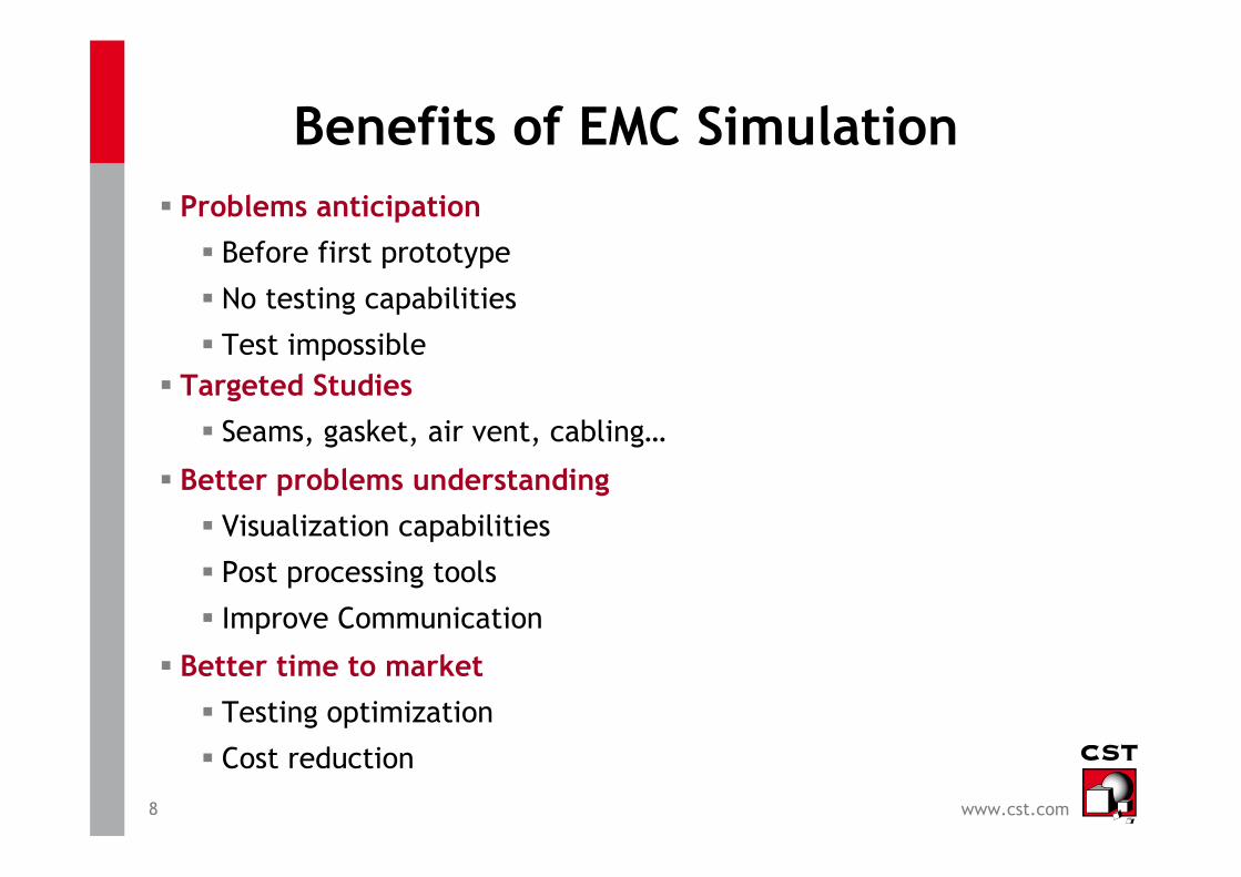
Benefits of EMC Simulation� Problems anticipation
� Before first prototype
� No testing capabilities
� Test impossible� Targeted Studies
� Seams, gasket, air vent, cabling…
� Better problems understanding
� Visualization capabilities
� Post processing tools
� Improve Communication
� Better time to market
� Testing optimization
� Cost reduction

9 www.cst.com
Use of Simulation Software in Pre-Qualification Tests
1. Short EMC Introduction2. Benefits of EMC Simulation3. Key points for a Successful EMC Simulation4. Illustration Examples
� Avionic
� Automotive
5. Conclusion
Royal Military College of Canada

10 www.cst.com
Key points for a successful EMC simulation
� EMC knowledge
•Component
•PCB
•Cabling
•System
•FIT PBA
•TLM
•PEEC
•TL
•Spice
� Model simplification� Geometry
� Material
� Adapted simulation tool

11 www.cst.com
Use of Simulation Software in Pre-Qualification Tests
1. Short EMC Introduction2. Benefits of EMC Simulation3. Key points for a Successful EMC Simulation4. Illustration Examples
� Avionic
� Automotive
5. Conclusion
Royal Military College of Canada

12 www.cst.com
Electromagnetic Interference Threat Posed by aWireless Network Inside a Passenger Aircraft
� EMI from PEDs on commercial aircraft has been suspected of causing anomalous events during flights for years.
� Documented EMI incidents include autopilot disconnects, erratic flight deck indications, course deviations and uncommented turns.
� Reports of EMI incidents on an aircraft are normally qualitative accounts, which can often be impossible to repeat due to the complex nature of the aircraft EME. The aircraft EM model
� presented herein offers a platform for examining a variety of EMC coupling scenarios in a controlled, repeatable environment.
� The EMI threat will be determined by comparing the numerical results obtained
Courtesy Capt Nicole L. Armstrong and Prof. Yahia M.M. Antar
Department of Electrical and Computer Engineering
Royal Military College of Canada

13 www.cst.com
Electromagnetic Interference Threat Posed by a
Wireless Network Inside a Passenger Aircraft
Courtesy Capt Nicole L. Armstrong and Prof. Yahia M.M. Antar
Department of Electrical and Computer Engineering
Royal Military College of Canada
EM Model• PEC background• Lossy windows• Walls, overhead bins and seats modeled with representative homogeneous, lossy dielectric shapes to include effect of details (cables and isolation in walls, baggage, blankets in overhead bins, etc.)Excitation• 800 MHz �/2 dipole (GSM 800 frequency band for cellular communication)•Dipole located in the centre aisle of row 21C (near the back of the passenger cabin).
Airbus A319 EM Model
800 MHz �/2 Dipole

14 www.cst.com
Validation of aircraft EM Model
Power received at 800 MHz along window seats of A319 cabin.
Despite highly variable measurement results, there is general agreement -> validity of developed A319 model
Courtesy Capt Nicole L. Armstrong and Prof. Yahia M.M. Antar
Department of Electrical and Computer Engineering
Royal Military College of Canada
15 www.cst.com
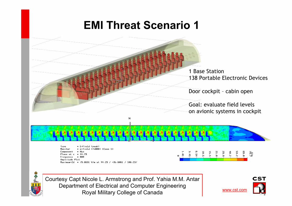
EMI Threat Scenario 1
Courtesy Capt Nicole L. Armstrong and Prof. Yahia M.M. Antar
Department of Electrical and Computer Engineering
Royal Military College of Canada
1 Base Station138 Portable Electronic Devices
Door cockpit – cabin open
Goal: evaluate field levels on avionic systems in cockpit

16 www.cst.com
Use of Simulation Software in Pre-Qualification Tests
1. Short EMC Introduction2. Benefits of EMC Simulation3. Key points for a Successful EMC Simulation4. Illustration Examples
� Avionic
� Automotive
5. Conclusion
Royal Military College of Canada

17 www.cst.com
Combining PCB, Enclosure and Cable Modeling for EMC Assessment of an
Automotive Module
Courtesy Scott Mee: Johnson Controls / David Johns: CST of America

18 www.cst.com
Case Study – Product Overview
�Instrument cluster
� Main board
� CAN, stepper motors, switching power supply, microcontroller, telltales
� Graphics board
� High speed memory bus and graphics controller
� TFT display board
� High-speed timing controller and internal switching power supplies
� Metal housing
�Interconnects
� 2 flexible cables used to connect between 3 boards (main, graphic, display)
Courtesy Scott Mee: Johnson Controls / David Johns: CST of America

19 www.cst.com
Case Study – Sources Of Emissions
�SDRAM memory clock (65MHz and harmonics)
� Main focus in this case study
�TFT pixel clock and data lines (not focus of this study)
�SSN (simultaneous switching noise) of high-speed IC’s (not focus of this study)
�Switched mode power supplies (not focus of this study)
Courtesy Scott Mee: Johnson Controls / David Johns: CST of America

20 www.cst.com
Case Study – Model “Build-Up” Process and
Simplifications
– Begin with detailed high-speed graphics PCB analysis (PEEC)
– Remove unwanted nets and generate equivalent source (equivalent currents)
– Model equivalent source in free space (TLM) and compare back to original
results from detailed PCB (validation)
– Add TFT display with metallic enclosure and shielded flexible cable
interconnect
– Model three board scenario (main, graphic � source, TFT) in free space
– Add CISPR 25 RF setup (ground plane, chamber floor, antenna, artificial
networks)
– Add single wire vehicle harness with termination into the artificial networks
Result � Trend model available for evaluating design alternatives
Note: Trend model does not predict EMC test results directly; it shows the
trends
Courtesy Scott Mee: Johnson Controls / David Johns: CST of America
21 www.cst.com
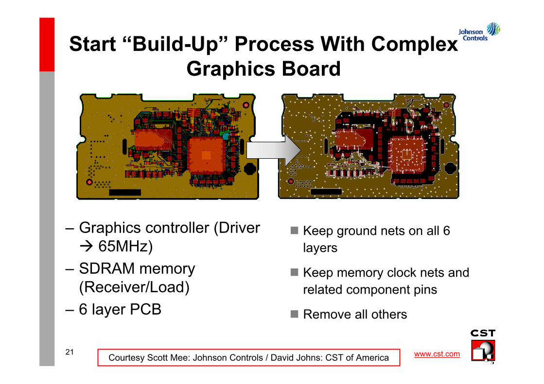
Start “Build-Up” Process With Complex
Graphics Board
– Graphics controller (Driver
� 65MHz)
– SDRAM memory
(Receiver/Load)
– 6 layer PCB
� Keep ground nets on all 6
layers
� Keep memory clock nets and
related component pins
� Remove all others
Courtesy Scott Mee: Johnson Controls / David Johns: CST of America

22 www.cst.com
Simulate Detailed Memory Clock Line
Using (PEEC) Method
– DRAM CLK net excited
using constant amplitude
1V swept frequency
signal
– Peak current density
shown over localized
region at 715 MHz
Receiver
Driver
Courtesy Scott Mee: Johnson Controls / David Johns: CST of America

23 www.cst.com
Generate Equivalent Source Model
Simplified Graphics Board (PEEC) Equivalent Model (TLM)
– Equivalence Principle
applied to create a fields-
based source
representation of the PCB
– Source attached to a
simplified reference plane in
3D TLM
– Enables more accurate
representation of source
without retaining all the PCB
detail
Near E Field
(715 MHz)
Courtesy Scott Mee: Johnson Controls / David Johns: CST of America

24 www.cst.com
Equivalent Source Model
Near Electric Field (715 MHz) Far Field Patterns (715 MHz)
Driven side of PCB
(field generated by
DRAM CLK net
clearly seen)
Opposite side of
PCB (field coupled
through vias and
wrapped around
edges of planes)
Courtesy Scott Mee: Johnson Controls / David Johns: CST of America

25 www.cst.com
Add TFT Display PCB & Metallic
Enclosure With Flexible Cable
Graphics PCB
Equivalent Source
Model
Flexible cable
spline model
TFT Display
Enclosure
TFT Display
PCB
Courtesy Scott Mee: Johnson Controls / David Johns: CST of America

26 www.cst.com
Add Main PCB With Flexible Cable
Flex Cable Modeled
As Extruded Spline
Main PCB
(slots in ground
plane maintained)
Assembled
instrument cluster
model
Courtesy Scott Mee: Johnson Controls / David Johns: CST of America

27 www.cst.com
Instrument Cluster Surface Currents
Surface Currents – 715 MHz
– Currents induced on main PCB due to coupling from graphics
PCB
– Slots in ground shapes on main PCB are electrically significant
– Slot resonances may enhance emissions near this frequency
Courtesy Scott Mee: Johnson Controls / David Johns: CST of America

28 www.cst.com
CISPR 25 Radiated Emissions Test Setup
�Mainly vehicle harness
radiation below 400-500MHz
�Limits are as low as
12dBuV/m in some key ranges
�What aspects should be
modeled?
�Chamber floor
�Absorber
�Ground plane/table
�Ground straps
�Loads
�LISNs
Courtesy Scott Mee: Johnson Controls / David Johns: CST of America

29 www.cst.com
CISPR 25 Chamber Model
Chamber Floor
Ground Plane
Isotropic Antenna
2 meter vehicle
harness
Instrument
Cluster Model
Artificial
Network
Courtesy Scott Mee: Johnson Controls / David Johns: CST of America

30 www.cst.com
CISPR 25 Chamber Analysis – Surface
CurrentGround Plane
Assembled Instrument ClusterHarness
Courtesy Scott Mee: Johnson Controls / David Johns: CST of America

31 www.cst.com
Case Study – Trend Model Completed
CISPR 25 simplifications
– Artificial network modeled as a simple circuit between the wire and
ground plane
– Vehicle wire harness reduced to a single wire (assume common-
mode)
– Antenna is assumed to be isotropic
– Assume absorbing boundary conditions for chamber walls and ceiling
Product model simplifications
– Source model simplified into an equivalent source modeling approach
– Main board ground shapes extracted rather than using completely
routed PCB
– Flex cables modeled using an extruded spline
– Display PCB modeled as a single conductive PCB layer
Courtesy Scott Mee: Johnson Controls / David Johns: CST of America

32 www.cst.com
Case Study – Three Design Alternatives
– Increase series resistance in SDRAM clock line (0 ohms � 460
ohms)
– Install PCB shield cover over graphics board circuits
– Add four ground contact springs between graphics board and TFT
display metallic enclosure
360 Ohm 100 Ohm
Graphics
PCB
shield
Spring
contacts
Courtesy Scott Mee: Johnson Controls / David Johns: CST of America

33 www.cst.com
Trends Analysis by Simulation
Broadband Response (Vertical Polarization)
2. As (1) +
Spring Contacts
Graphics PCB to
TFT
1. Initial Design
4. As (3) + 460 Ohms
Series R CLK Net
3. As (2) +
Graphics
PCB Shield
Courtesy Scott Mee: Johnson Controls / David Johns: CST of America
34 www.cst.com
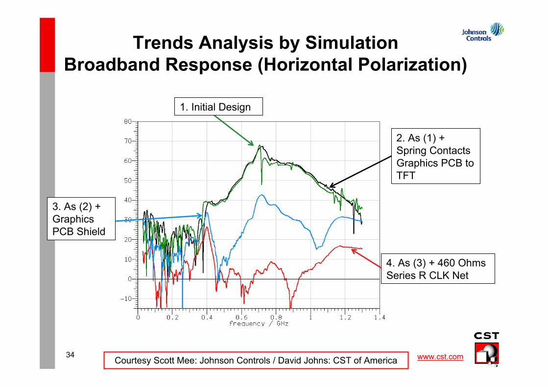
Trends Analysis by Simulation
Broadband Response (Horizontal Polarization)
2. As (1) +
Spring Contacts
Graphics PCB to
TFT
1. Initial Design
4. As (3) + 460 Ohms
Series R CLK Net
3. As (2) +
Graphics
PCB Shield
Courtesy Scott Mee: Johnson Controls / David Johns: CST of America

35 www.cst.com
Validation
Comparison of Trends in Simulation and Testing
Before Shield
After Shield
Before Shield
After Shield
Test Results Simulation Results
Courtesy Scott Mee: Johnson Controls / David Johns: CST of America

36 www.cst.com
Validation
Comparison of Trends in Simulation and Testing
Before Series R
After Series R
Before Series R
After Series R
Test Results Simulation Results
Courtesy Scott Mee: Johnson Controls / David Johns: CST of America

37 www.cst.com
Conclusions
– Simplified model follows the trends found during physical testing
– Design alternatives had more impact at higher frequencies
– Simulation times and model development resources were in-line with
practical expectations of product development
– Results indicate the influence of the addition of the test setup, added
cables and electronics
– Simulations were run on a dual processor quad-core Dell T7500
workstation with 32 GB RAM
– PCB (PEEC) simulation approximately 20 minutes
– Full system (TLM) simulation approximately 2 hours and 388 MB
RAM
Courtesy Scott Mee: Johnson Controls / David Johns: CST of America
38 www.cst.com
Use of Simulation Software in Pre-Qualification Tests
1. Short EMC Introduction2. Benefits of EMC Simulation3. Key points for a Successful EMC Simulation4. Illustration Examples
� Avionic
� Automotive
5. Conclusion
Royal Military College of Canada

39 www.cst.com
Conclusion
� The goal of a simulation tool is not to replace the EMC Tests but to reduce the number of those.
� It must help the engineers to be more confident before the finalcompliance test by showing the potential threads in advance and validating his solutions.
� Keep in mind that prior to doing EMC simulations, your are doingEMC!
� No need to be a numerical method specialist to use our simulation solutions for emc but you need to be an EMC specialist.