Use of Data Comm by Flight Crew to Conduct Interval ... Institute of Aeronautics and Astronautics 1...
18
American Institute of Aeronautics and Astronautics 1 Use of Data Comm by Flight Crew to Conduct Interval Management Operations to Parallel Dependent Runways Brian T. Baxley 1 NASA Langley Research Center, Hampton, VA, 23681 Clay Hubbs 2 and Rick Shay 3 National Institute of Aerospace (NIA), Hampton, VA, 23666 and James Karanian 4 Air Traffic Group, Mansfield, TX, 76063 The Interval Management (IM) concept is being developed as a method to maintain or increase high traffic density airport arrival throughput while allowing aircraft to conduct near idle thrust descents. The Interval Management with Spacing to Parallel Dependent Runways (IMSPiDR1) experiment at NASA Langley Research Center used 24 commercial pilots to examine IM procedures to conduct parallel dependent runway arrival operations while maintaining safe but efficient intervals behind the preceding aircraft. The use of IM procedures during these operations requires a lengthy and complex clearance from Air Traffic Control (ATC) to the participating aircraft, thereby making the use of Controller Pilot Data Link Communications (CPDLC) highly desirable as the communication method. The use of CPDLC reduces the need for voice transmissions between controllers and flight crew, and enables automated transfer of IM clearance elements into flight management systems or other aircraft avionics. The result is reduced crew workload and an increase in the efficiency of crew procedures. This paper focuses on the subset of data collected related to the use of CPDLC for IM operations into a busy airport. Overall, the experiment and results were very successful, with the mean time under 43 seconds for the flight crew to load the clearance into the IM spacing tool, review the calculated speed, and respond to ATC. An overall mean rating of ‘Moderately Agree’ was given when the crews were asked if the use of CPDLC was operationally acceptable as simulated in this experiment. Approximately half of the flight crew reported the use of CPDLC below 10,000’ for IM operations was unacceptable, with 83% reporting below 5000’ was unacceptable. Also described are proposed modifications to the IM operations that may reduce CPDLC ‘Respond’ time to less than 30 seconds and should significantly reduce the complexity of crew procedures, as well as follow-on research issues for operational use of CPDLC during IM operations. Nomenclature ADS-B = Automatic Dependent Surveillance – Broadcast ASTAR = Airborne Spacing for Terminal Arrivals ASTOR = Aircraft Simulation for Traffic Operations Research ATOL = Air Traffic Operations Laboratory CPDLC = Controller-Pilot Datalink Communications DTS = Development and Test Simulator EICAS = Engine Indicating and Crew Alerting System FAS = Final Approach Speed (V ref30 +5 used in this experiment) IAP = Instrument Approach Procedure IFD = Integration Flight Deck ILS = Instrument Landing System IM = Interval Management IM-S = Interval Management with Spacing 1 Research Engineer, Crew Systems and Aviation Operations Branch, AIAA Senior Member. 2 Aviation Consultant, AAAInnovate, AIAA Member. 3 Aviation Consultant, President, Double Black Aviation Technology L.L.C., AIAA Senior Member. 4 President, Air Traffic Group LLC., Aviation Consultant to FAA AJE. https://ntrs.nasa.gov/search.jsp?R=20110015876 2018-07-09T08:08:17+00:00Z
Transcript of Use of Data Comm by Flight Crew to Conduct Interval ... Institute of Aeronautics and Astronautics 1...
American Institute of Aeronautics and Astronautics
1
Use of Data Comm by Flight Crew to Conduct Interval Management Operations to Parallel Dependent Runways
Brian T. Baxley1
NASA Langley Research Center, Hampton, VA, 23681
Clay Hubbs2 and Rick Shay3 National Institute of Aerospace (NIA), Hampton, VA, 23666
and
James Karanian4 Air Traffic Group, Mansfield, TX, 76063
The Interval Management (IM) concept is being developed as a method to maintain or increase high traffic density airport arrival throughput while allowing aircraft to conduct near idle thrust descents. The Interval Management with Spacing to Parallel Dependent Runways (IMSPiDR1) experiment at NASA Langley Research Center used 24 commercial pilots to examine IM procedures to conduct parallel dependent runway arrival operations while maintaining safe but efficient intervals behind the preceding aircraft. The use of IM procedures during these operations requires a lengthy and complex clearance from Air Traffic Control (ATC) to the participating aircraft, thereby making the use of Controller Pilot Data Link Communications (CPDLC) highly desirable as the communication method. The use of CPDLC reduces the need for voice transmissions between controllers and flight crew, and enables automated transfer of IM clearance elements into flight management systems or other aircraft avionics. The result is reduced crew workload and an increase in the efficiency of crew procedures. This paper focuses on the subset of data collected related to the use of CPDLC for IM operations into a busy airport. Overall, the experiment and results were very successful, with the mean time under 43 seconds for the flight crew to load the clearance into the IM spacing tool, review the calculated speed, and respond to ATC. An overall mean rating of ‘Moderately Agree’ was given when the crews were asked if the use of CPDLC was operationally acceptable as simulated in this experiment. Approximately half of the flight crew reported the use of CPDLC below 10,000’ for IM operations was unacceptable, with 83% reporting below 5000’ was unacceptable. Also described are proposed modifications to the IM operations that may reduce CPDLC ‘Respond’ time to less than 30 seconds and should significantly reduce the complexity of crew procedures, as well as follow-on research issues for operational use of CPDLC during IM operations.
Nomenclature ADS-B = Automatic Dependent Surveillance – Broadcast ASTAR = Airborne Spacing for Terminal Arrivals ASTOR = Aircraft Simulation for Traffic Operations Research ATOL = Air Traffic Operations Laboratory CPDLC = Controller-Pilot Datalink Communications DTS = Development and Test Simulator EICAS = Engine Indicating and Crew Alerting System FAS = Final Approach Speed (Vref30+5 used in this experiment) IAP = Instrument Approach Procedure IFD = Integration Flight Deck ILS = Instrument Landing System IM = Interval Management IM-S = Interval Management with Spacing 1 Research Engineer, Crew Systems and Aviation Operations Branch, AIAA Senior Member. 2 Aviation Consultant, AAAInnovate, AIAA Member. 3 Aviation Consultant, President, Double Black Aviation Technology L.L.C., AIAA Senior Member. 4 President, Air Traffic Group LLC., Aviation Consultant to FAA AJE.
https://ntrs.nasa.gov/search.jsp?R=20110015876 2018-07-09T08:08:17+00:00Z
American Institute of Aeronautics and Astronautics
2
MCDU = Multi-function Control and Display Unit MCP = Mode Control Panel OPD = Optimized Profile Descent PFD = Primary Flight Display RTA = Required Time of Arrival STAR = Standard Terminal Arrival Route
I. Introduction he Joint Planning and Development Office (JPDO) document “Concept of Operations for the Next Generation Air Transportation System” describes a 2025 air traffic system that will experience significant growth, and to
achieve the increased capacity while maintaining safety, many new technologies and procedures will have to be developed and tested.1 Over the past five years, NASA’s Airspace Systems Project has conducted research in collaboration with the FAA, the aviation industry, and academia to address many of the issues identified in that document. NASA’s research of the JPDO’s “super-density operations,” or arrival and departure operations at busy major airports, explores and develops technologies and procedures designed to increase runway throughput, reduce flight delay and fuel burn, and improve predictability.2 Examples include research at NASA Ames Research Center focusing on time-deconflicted scheduling for the air traffic controllers, 3,4,5 and at NASA Langley Research Center exploring precision control to that schedule by the flight crew.6,7
The NASA Langley research of precision control for arrival operations began in the 1970’s by exploring ‘constant distance’ and ‘constant time’ spacing techniques along a common trajectory, with onboard information and software used to enable the aircraft to independently achieve Air Traffic Control’s (ATC) operational goal. These concepts and algorithms have matured into a trajectory-based algorithm that accommodates complex route structures arriving to the airport from all directions. The speed for the flight crew to fly can be based on calculations to arrive at the runway threshold at a specified time, or calculated based on achieving a specified time interval behind the preceding aircraft.8 In 2006, the NASA Langley research team joined the Interval Management (IM) working group, led by the Federal Aviation Administration (FAA) Surveillance Broadcast Services (SBS) Office. This group contained members from the FAA, controllers, pilots, researchers, and aircraft avionic manufactures, and drafted a concept of operations for air traffic management procedures that would capitalize on the aircraft’s onboard ability to precisely control to an assigned spacing.9 This document was a significant contribution to a larger effort by the FAA and EUROCONTROL to internationally harmonize and document the Interval Management procedure, define requirements, asses safety and performance, and analyze expected flight crew tasks.10 This FAA/EUROCONTROL document was in turn used by NASA Langley researchers to develop an internal concept for precision spacing of aircraft during arrival operations to dependent parallel runways, which was the concept of operations for this experiment.11 The concept, scenarios, procedures, communication requirements, and research issues from these documents were used to create the experiment plan for the research described in this paper. Assisting the NASA Langley researchers in this yearlong effort from experiment design to data analysis and report writing were subject matter experts for flight crew operations (Hubbs and Shay), as well as a designated point-of-contact from the FAA ATO Office for Efficient Flows into Congested Airspace (Karanian).12 All the documents listed in this paragraph describe Interval Management with Spacing (IM-S), which specifically and intentionally has ATC retain the responsibility for safe separation of aircraft. Throughout the development of the IM concept, two technologies envisioned as part of the air traffic management environment that enable these procedures are Automatic Dependent Surveillance - Broadcast (ADS-B) and Controller - Pilot Datalink Communication (CPDLC).
Interval Management with Spacing to Parallel Dependent Runways (IMSPiDR1) was a human-in-the-loop experiment conducted in June 2011 at NASA Langley with 24 commercial pilots flying arrivals to runways using dependent parallel operations at Dallas Fort-Worth airport (KDFW). The overall goal of the experiment was to examine the ability of airborne spacing software and procedures to support ATC by precisely delivering aircraft at the runway in both in-trail and dependent parallel runway operations. This paper documents the CPDLC related areas of the experiment, to include the CPDLC message used by ATC to communicate the IM-S clearance, pilot procedures in the cockpit to accept and implement the clearance, pilot response time using CPDLC, and subjective feedback from the pilots about the acceptability of the IM concept and procedure. Simple CPDLC messages such as ‘Transfer of Communications,’ ‘Beacon Code’ changes, and ‘Altitude,’ ‘Speed,’ and ‘Heading’ changes were not part of this study. A more complete description of the experiment, facilities, displays, and analysis of all hypotheses was published in reference 13.
T
American Institute of Aeronautics and Astronautics
3
Future research is planned to explore the use of voice as the communication between controllers and pilots, target aircraft data from sources other than ADS-B, integration of the airborne spacing algorithm with more advanced ground-based scheduling software,14 and seamless interoperability with new controller decision support software to precisely space aircraft.15
II. Interval Management with Spacing to Parallel Dependent Runways
A. IM-S to Parallel Dependent Runways Concept A key to airport efficiency is the ability to schedule, and then manage, the aircraft-to-aircraft spacing at runway
thresholds. The IM-S concept employs both a ground-based scheduling component and a flight deck-based spacing component. The ground-based component is software that creates an optimized schedule of arrival times for all aircraft to each runway, the spacing between those aircraft, and then provides the controller a message to send to the flight crew. The controller sends the message and delegates control of the aircraft’s speed to the flight crew for them to achieve this precise spacing at the runway threshold. The flight-deck based spacing software, called Airborne Spacing for Terminal Arrival Routes (ASTAR) calculates the speed for the crew to fly based on the specified 4D trajectory of ownship and traffic to follow to achieve the assigned spacing interval.16 Previous work has focused on single runway operations; however, several airports routinely conduct parallel approach operations. Depending upon the airport layout and surveillance infrastructure, different types of operations are performed on the parallel approaches, and sometimes the arrivals to one of the parallel runways are dependent upon the arrivals to the other.
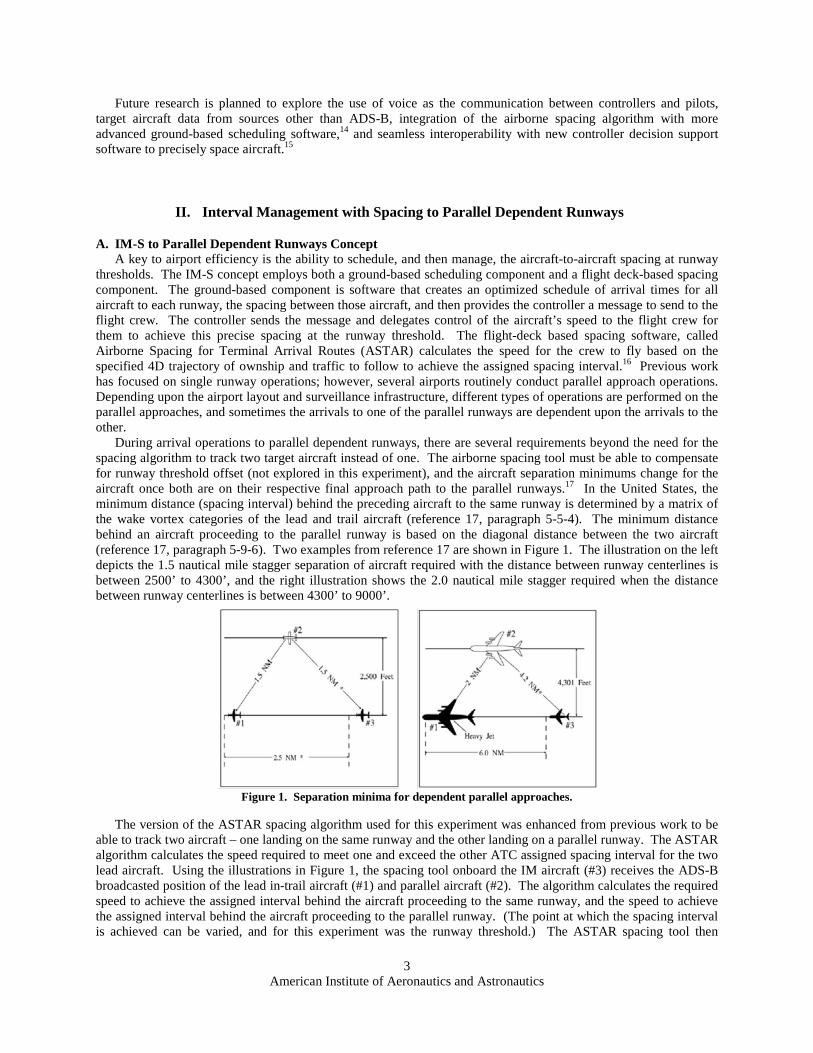
During arrival operations to parallel dependent runways, there are several requirements beyond the need for the spacing algorithm to track two target aircraft instead of one. The airborne spacing tool must be able to compensate for runway threshold offset (not explored in this experiment), and the aircraft separation minimums change for the aircraft once both are on their respective final approach path to the parallel runways.17 In the United States, the minimum distance (spacing interval) behind the preceding aircraft to the same runway is determined by a matrix of the wake vortex categories of the lead and trail aircraft (reference 17, paragraph 5-5-4). The minimum distance behind an aircraft proceeding to the parallel runway is based on the diagonal distance between the two aircraft (reference 17, paragraph 5-9-6). Two examples from reference 17 are shown in Figure 1. The illustration on the left depicts the 1.5 nautical mile stagger separation of aircraft required with the distance between runway centerlines is between 2500’ to 4300’, and the right illustration shows the 2.0 nautical mile stagger required when the distance between runway centerlines is between 4300’ to 9000’.
Figure 1. Separation minima for dependent parallel approaches.
The version of the ASTAR spacing algorithm used for this experiment was enhanced from previous work to be able to track two aircraft – one landing on the same runway and the other landing on a parallel runway. The ASTAR algorithm calculates the speed required to meet one and exceed the other ATC assigned spacing interval for the two lead aircraft. Using the illustrations in Figure 1, the spacing tool onboard the IM aircraft (#3) receives the ADS-B broadcasted position of the lead in-trail aircraft (#1) and parallel aircraft (#2). The algorithm calculates the required speed to achieve the assigned interval behind the aircraft proceeding to the same runway, and the speed to achieve the assigned interval behind the aircraft proceeding to the parallel runway. (The point at which the spacing interval is achieved can be varied, and for this experiment was the runway threshold.) The ASTAR spacing tool then
American Institute of Aeronautics and Astronautics
4
displays to the flight crew the slower of the two speeds, ensuring that the IM aircraft (#3) meets one of the two ATC assigned spacing intervals and exceeds the other.
B. Data Comm Messages for IM Operations CPDLC was used to transfer information from the controller and ground based scheduling software, to the flight
crew and the flight deck based spacing software (FIM). The content and format of the CPDLC message uplinks and downlinks containing the arrival, approach, and IM clearance in this experiment was based on documents from the FAA’s SBS Office IM working group, the FAA Data Comm Office, and RTCA / EUROCAE committees.10,18,19,20 The majority of commercial aircraft today do not have the capability to precisely achieve a RTA (Required Time of Arrival) while in a descent. To enable comparison of RTA to IM operations, the ASTAR algorithm was also used in an RTA only mode during this research experiment. The RTA clearance retained the same structure and wording as the IM clearance message, with data elements referring to relative spacing behind the two lead aircraft removed. The phrase ‘Expect IM-Spacing’ was left in the message as a reminder to the crew to use ASTAR data entry procedures, and not current day FMC procedures for RTA data entry.
• RTA clearance to the runway threshold
CROSS R-17C AT 0028:26Z. ACHIEVE BY R-17C. TERMINATE AT R-17C. EXPECT IM-SPACING.
The IM clearance information elements defined in the ASPA-FIM document (reference 10, paragraph 4.4.3) are
for a range of IM operations to include departures, enroute, oceanic, and arrival operations. The elements pertinent to parallel dependent runway arrival operations and incorporated in this experiment were:
• Target aircraft identification (call signs of the lead in-trail and parallel aircraft) • Assigned spacing goal (seconds for in-trail aircraft, and nautical miles for parallel aircraft) • IM clearance type (achieve then maintain assigned spacing interval) • Achieve - By - Point (runway threshold, could be modified in future research) • Termination Point (runway threshold could be modified in future research) • Target aircraft intended flight path information (arrival and approach procedure)
Four additional information elements were added to the above list for the IMSPiDR1 experiment. First, an RTA
(used synonymously with Scheduled Time of Arrival in this experiment) to the runway threshold was included to enable the flight crew to begin operating the aircraft towards the location desired by ATC even when outside of air-to-air ADS-B reception range. The RTA function normally associated with commercially available Flight Management Systems (FMS) was not used in this experiment. The ASTAR10 algorithm uses the RTA to provide speed guidance until valid ADS-B data is available. Second, the CPDLC message includes the text ‘WHEN ABLE’ to make the IM clearance conditional, that is the speed flown is based on the assigned time at the runway threshold until the aircraft is within ADS-B range of a lead aircraft, at which time the commanded ASTAR speed will be based on the lead aircraft’s position. Third, the lead aircraft’s final approach speed was included based on previous IM research that has shown significant improvement in delivery precision when the ASTAR spacing tool compensates for differences in those speeds.6 Finally, a November 2010 IM workshop attended by the FAA, NASA, MITRE, pilots, and controllers generated a request that the experiment include the flight crew notifying ATC when the spacing tool transitions from a speed based on the RTA, to a speed based on the spacing interval behind the target aircraft. The concern was commanded speed from the spacing tool, and therefore the aircraft’s position, may be different enough between absolute (RTA) and relative spacing (IM) to create operational issues for the air traffic controllers.
To enable the onboard spacing tool to support dependent parallel runway operations, all the information elements in the preceding two paragraphs about both lead aircraft were sent to the flight crew receiving the IM clearance. Shown immediately below is an example of a two aircraft IM clearance containing all these elements for an aircraft arriving to Runway 17C at KDFW.
• RTA plus IM (RTA+IM) clearance for two lead aircraft
CROSS R-17C AT 0028:26Z. WHEN ABLE CLEARED IM-SPACING 95 SEC WITH NASA1 AND 2.2 NM WITH NASA2. ACHIEVE BY R-17C. TERMINATE AT R-17C. NASA1 ROUTE GGG CQY6 PENNY ILS17C, FAS 130 KT. NASA2 ROUTE INK JEN9 YOHAN ILS18R, FAS 130 KT. REPORT COMMENCING IM-SPACING.
American Institute of Aeronautics and Astronautics
5
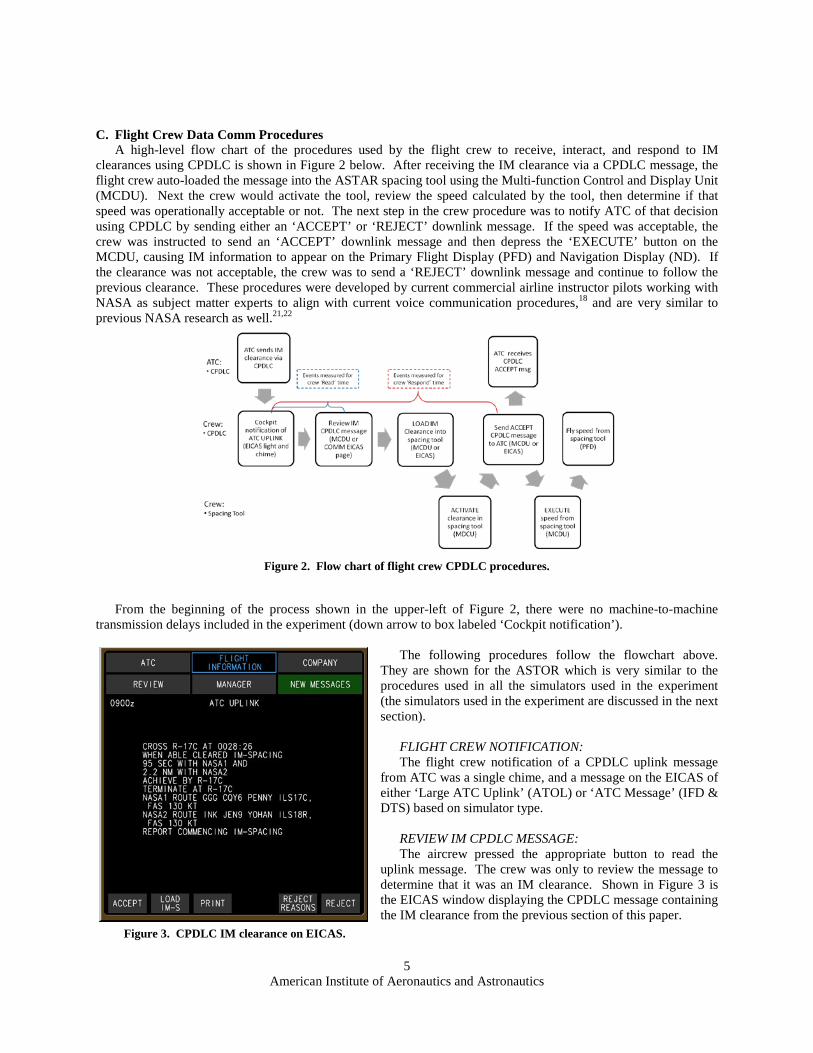
C. Flight Crew Data Comm Procedures A high-level flow chart of the procedures used by the flight crew to receive, interact, and respond to IM
clearances using CPDLC is shown in Figure 2 below. After receiving the IM clearance via a CPDLC message, the flight crew auto-loaded the message into the ASTAR spacing tool using the Multi-function Control and Display Unit (MCDU). Next the crew would activate the tool, review the speed calculated by the tool, then determine if that speed was operationally acceptable or not. The next step in the crew procedure was to notify ATC of that decision using CPDLC by sending either an ‘ACCEPT’ or ‘REJECT’ downlink message. If the speed was acceptable, the crew was instructed to send an ‘ACCEPT’ downlink message and then depress the ‘EXECUTE’ button on the MCDU, causing IM information to appear on the Primary Flight Display (PFD) and Navigation Display (ND). If the clearance was not acceptable, the crew was to send a ‘REJECT’ downlink message and continue to follow the previous clearance. These procedures were developed by current commercial airline instructor pilots working with NASA as subject matter experts to align with current voice communication procedures,18 and are very similar to previous NASA research as well.21,22
Figure 2. Flow chart of flight crew CPDLC procedures.
From the beginning of the process shown in the upper-left of Figure 2, there were no machine-to-machine
transmission delays included in the experiment (down arrow to box labeled ‘Cockpit notification’). The following procedures follow the flowchart above.
They are shown for the ASTOR which is very similar to the procedures used in all the simulators used in the experiment (the simulators used in the experiment are discussed in the next section).
FLIGHT CREW NOTIFICATION: The flight crew notification of a CPDLC uplink message
from ATC was a single chime, and a message on the EICAS of either ‘Large ATC Uplink’ (ATOL) or ‘ATC Message’ (IFD & DTS) based on simulator type.
REVIEW IM CPDLC MESSAGE: The aircrew pressed the appropriate button to read the
uplink message. The crew was only to review the message to determine that it was an IM clearance. Shown in Figure 3 is the EICAS window displaying the CPDLC message containing the IM clearance from the previous section of this paper.
Figure 3. CPDLC IM clearance on EICAS.
American Institute of Aeronautics and Astronautics
6
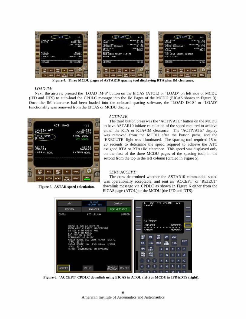
Figure 4. Three MCDU pages of ASTAR10 spacing tool displaying RTA plus IM clearance.
LOAD IM: Next, the aircrew pressed the ‘LOAD IM-S’ button on the EICAS (ATOL) or ‘LOAD’ on left side of MCDU
(IFD and DTS) to auto-load the CPDLC message into the IM Pages of the MCDU (EICAS shown in Figure 3). Once the IM clearance had been loaded into the onboard spacing software, the ‘LOAD IM-S’ or ‘LOAD’ functionality was removed from the EICAS or MCDU display.
ACTIVATE: The third button press was the ‘ACTIVATE’ button on the MCDU
to have ASTAR10 initiate calculation of the speed required to achieve either the RTA or RTA+IM clearance. The ‘ACTIVATE’ display was removed from the MCDU after the button press, and the ‘EXECUTE’ light was illuminated. The spacing tool required 15 to 20 seconds to determine the speed required to achieve the ATC assigned RTA or RTA+IM clearance. This speed was displayed only on the first of the three MCDU pages of the spacing tool, in the second from the top in the left column (circled in Figure 5).
SEND ACCEPT: The crew determined whether the ASTAR10 commanded speed
was operationally acceptable, and sent an ‘ACCEPT’ or ‘REJECT’ downlink message via CPDLC as shown in Figure 6 either from the EICAS page (ATOL) or the MCDU (the IFD and DTS).
Figure 6. ‘ACCEPT’ CPDLC downlink using EICAS in ATOL (left) or MCDU in IFD&DTS (right).
Figure 5. ASTAR speed calculation.
American Institute of Aeronautics and Astronautics
7
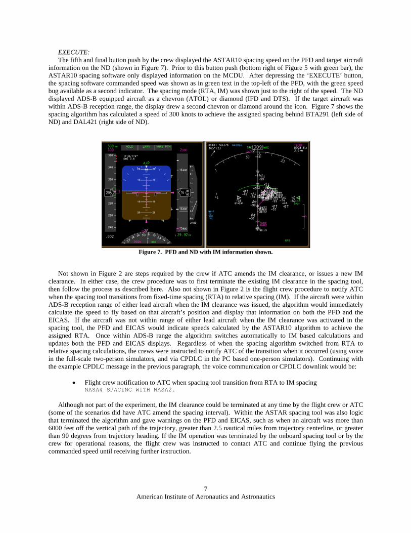
EXECUTE: The fifth and final button push by the crew displayed the ASTAR10 spacing speed on the PFD and target aircraft
information on the ND (shown in Figure 7). Prior to this button push (bottom right of Figure 5 with green bar), the ASTAR10 spacing software only displayed information on the MCDU. After depressing the ‘EXECUTE’ button, the spacing software commanded speed was shown as in green text in the top-left of the PFD, with the green speed bug available as a second indicator. The spacing mode (RTA, IM) was shown just to the right of the speed. The ND displayed ADS-B equipped aircraft as a chevron (ATOL) or diamond (IFD and DTS). If the target aircraft was within ADS-B reception range, the display drew a second chevron or diamond around the icon. Figure 7 shows the spacing algorithm has calculated a speed of 300 knots to achieve the assigned spacing behind BTA291 (left side of ND) and DAL421 (right side of ND).
Figure 7. PFD and ND with IM information shown.
Not shown in Figure 2 are steps required by the crew if ATC amends the IM clearance, or issues a new IM
clearance. In either case, the crew procedure was to first terminate the existing IM clearance in the spacing tool, then follow the process as described here. Also not shown in Figure 2 is the flight crew procedure to notify ATC when the spacing tool transitions from fixed-time spacing (RTA) to relative spacing (IM). If the aircraft were within ADS-B reception range of either lead aircraft when the IM clearance was issued, the algorithm would immediately calculate the speed to fly based on that aircraft’s position and display that information on both the PFD and the EICAS. If the aircraft was not within range of either lead aircraft when the IM clearance was activated in the spacing tool, the PFD and EICAS would indicate speeds calculated by the ASTAR10 algorithm to achieve the assigned RTA. Once within ADS-B range the algorithm switches automatically to IM based calculations and updates both the PFD and EICAS displays. Regardless of when the spacing algorithm switched from RTA to relative spacing calculations, the crews were instructed to notify ATC of the transition when it occurred (using voice in the full-scale two-person simulators, and via CPDLC in the PC based one-person simulators). Continuing with the example CPDLC message in the previous paragraph, the voice communication or CPDLC downlink would be:
• Flight crew notification to ATC when spacing tool transition from RTA to IM spacing
NASA4 SPACING WITH NASA2. Although not part of the experiment, the IM clearance could be terminated at any time by the flight crew or ATC
(some of the scenarios did have ATC amend the spacing interval). Within the ASTAR spacing tool was also logic that terminated the algorithm and gave warnings on the PFD and EICAS, such as when an aircraft was more than 6000 feet off the vertical path of the trajectory, greater than 2.5 nautical miles from trajectory centerline, or greater than 90 degrees from trajectory heading. If the IM operation was terminated by the onboard spacing tool or by the crew for operational reasons, the flight crew was instructed to contact ATC and continue flying the previous commanded speed until receiving further instruction.
American Institute of Aeronautics and Astronautics
8
III. Experiment Design Overview
A. Experiment Objectives The objectives of the IMSPiDR1 experiment were: 1) examine the spacing algorithm’s performance in terms of
the precision of aircraft delivery to the runway threshold and the stability of the aircraft arrival streams, 2) observe flight crew interactions with the algorithm, 3) evaluate requirements for ATC-flight crew communication via CPDLC, and 4) collect pilots’ reported workload levels and ratings of the acceptability of the IM-S concept, procedures, speed guidance, and display interface they were asked to utilize. This paper discusses the results and conclusions about use of CPDLC for ATC-flight crew communications for IM operations in arrival operations.
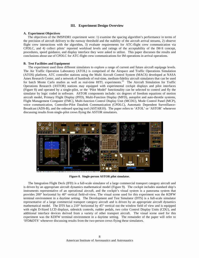
B. Test Facilities and Equipment The experiment used three different simulators to explore a range of current and future aircraft equipage levels.
The Air Traffic Operation Laboratory (ATOL) is comprised of the Airspace and Traffic Operations Simulation (ATOS) platform, ATC controller stations using the Multi Aircraft Control System (MACS) developed at NASA Ames Research Center, and a network of hundreds of real-time, medium-fidelity aircraft simulators that can be used for batch Monte Carlo studies as well as real-time HITL experiments.23 The Aircraft Simulation for Traffic Operations Research (ASTOR) stations may equipped with experimental cockpit displays and pilot interfaces (Figure 8) and operated by a single-pilot, or the ‘Pilot Model’ functionality can be selected to control and fly the simulator by logic coded in software. ASTOR components include: six degrees of freedom equations of motion aircraft model, Primary Flight Display (PFD), Multi-Function Display (MFD), autopilot and auto-throttle systems, Flight Management Computer (FMC), Multi-function Control Display Unit (MCDU), Mode Control Panel (MCP), voice communication, Controller-Pilot Datalink Communication (CPDLC), Automatic Dependent Surveillance-Broadcast (ADS-B), and the onboard spacing tool (ASTAR10). The paper refers to ‘ATOL’ or ‘ASTOR’ whenever discussing results from single-pilot crews flying the ASTOR simulators.
Figure 8. Single-person ASTOR pilot simulator.
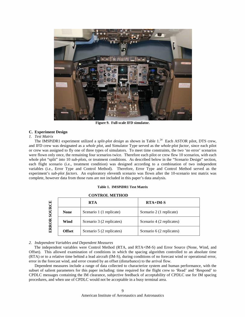
The Integration Flight Deck (IFD) is a full-scale simulator of a large commercial transport category aircraft and is driven by an appropriate aircraft dynamics mathematical model (Figure 9). The cockpit includes standard ship’s instruments representative of an operational aircraft, and the cockpit’s visual system is a panorama system that provides 200° horizontal by 40° vertical field-of-view. The visual scene used for this experiment was the KDFW terminal environment in a daytime setting. The Development and Test Simulator (DTS) is a full-scale simulator representative of a large commercial transport category aircraft and is driven by an appropriate aircraft dynamics mathematical model. The DTS has a 210° horizontal by 45° vertical out the window field of view and is equipped with eight D-Sized LCD displays, sidestick controls, rudder pedals, two color Control Display Units (CDU), and additional interface devices derived from a variety of other transport aircraft. The visual scene used for this experiment was the KDFW terminal environment in a daytime setting. The remainder of the paper will refer to ‘IFD&DTS’ whenever discussing results from the two-person crews flying these simulators.
American Institute of Aeronautics and Astronautics
9
Figure 9. Full-scale IFD simulator.
C. Experiment Design 1. Test Matrix
The IMSPiDR1 experiment utilized a split-plot design as shown in Table 1.24 Each ASTOR pilot, DTS crew, and IFD crew was designated as a whole plot, and Simulator Type served as the whole-plot factor, since each pilot or crew was assigned to fly one of three types of simulators. To meet time constraints, the two ‘no error’ scenarios were flown only once, the remaining four scenarios twice. Therefore each pilot or crew flew 10 scenarios, with each whole plot “split” into 10 sub-plots, or treatment conditions. As described below in the “Scenario Design” section, each flight scenario (i.e., treatment condition) was designed according to a combination of two independent variables (i.e., Error Type and Control Method). Therefore, Error Type and Control Method served as the experiment’s sub-plot factors. An exploratory eleventh scenario was flown after the 10-scenario test matrix was complete, however data from those runs are not included in this paper’s data analysis.
Table 1. IMSPiDR1 Test Matrix
CONTROL METHOD
ER
RO
R S
OU
RC
E
RTA RTA+IM-S
None Scenario 1 (1 replicate) Scenario 2 (1 replicate)
Wind Scenario 3 (2 replicates) Scenario 4 (2 replicates)
Offset Scenario 5 (2 replicates) Scenario 6 (2 replicates)
2. Independent Variables and Dependent Measures
The independent variables were Control Method (RTA, and RTA+IM-S) and Error Source (None, Wind, and Offset). This allowed examination of conditions in which the spacing algorithm controlled to an absolute time (RTA) or to a relative time behind a lead aircraft (IM-S), during conditions of no forecast wind or operational error, error in the forecast wind, and error created by an offset (disturbance) to the arrival flow.
Dependent measures include a range of data collected to characterize system and human performance, with the subset of salient parameters for this paper including: time required for the flight crew to ‘Read’ and ‘Respond’ to CPDLC messages containing the IM clearance, subjective feedback of acceptability of CPDLC use for IM spacing procedures, and when use of CPDLC would not be acceptable in a busy terminal area.
American Institute of Aeronautics and Astronautics
10
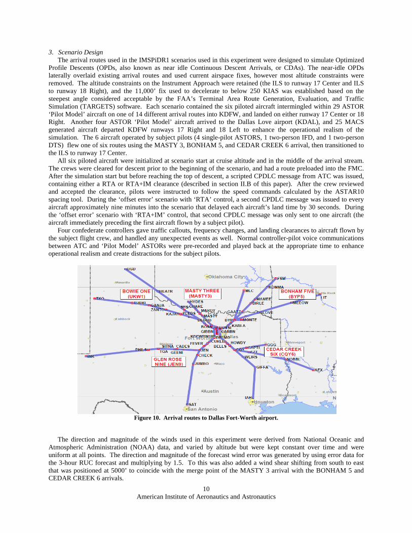
3. Scenario Design The arrival routes used in the IMSPiDR1 scenarios used in this experiment were designed to simulate Optimized
Profile Descents (OPDs, also known as near idle Continuous Descent Arrivals, or CDAs). The near-idle OPDs laterally overlaid existing arrival routes and used current airspace fixes, however most altitude constraints were removed. The altitude constraints on the Instrument Approach were retained (the ILS to runway 17 Center and ILS to runway 18 Right), and the 11,000’ fix used to decelerate to below 250 KIAS was established based on the steepest angle considered acceptable by the FAA’s Terminal Area Route Generation, Evaluation, and Traffic Simulation (TARGETS) software. Each scenario contained the six piloted aircraft intermingled within 29 ASTOR ‘Pilot Model’ aircraft on one of 14 different arrival routes into KDFW, and landed on either runway 17 Center or 18 Right. Another four ASTOR ‘Pilot Model’ aircraft arrived to the Dallas Love airport (KDAL), and 25 MACS generated aircraft departed KDFW runways 17 Right and 18 Left to enhance the operational realism of the simulation. The 6 aircraft operated by subject pilots (4 single-pilot ASTORS, 1 two-person IFD, and 1 two-person DTS) flew one of six routes using the MASTY 3, BONHAM 5, and CEDAR CREEK 6 arrival, then transitioned to the ILS to runway 17 Center.
All six piloted aircraft were initialized at scenario start at cruise altitude and in the middle of the arrival stream. The crews were cleared for descent prior to the beginning of the scenario, and had a route preloaded into the FMC. After the simulation start but before reaching the top of descent, a scripted CPDLC message from ATC was issued, containing either a RTA or RTA+IM clearance (described in section II.B of this paper). After the crew reviewed and accepted the clearance, pilots were instructed to follow the speed commands calculated by the ASTAR10 spacing tool. During the ‘offset error’ scenario with ‘RTA’ control, a second CPDLC message was issued to every aircraft approximately nine minutes into the scenario that delayed each aircraft’s land time by 30 seconds. During the ‘offset error’ scenario with ‘RTA+IM’ control, that second CPDLC message was only sent to one aircraft (the aircraft immediately preceding the first aircraft flown by a subject pilot).
Four confederate controllers gave traffic callouts, frequency changes, and landing clearances to aircraft flown by the subject flight crew, and handled any unexpected events as well. Normal controller-pilot voice communications between ATC and ‘Pilot Model’ ASTORs were pre-recorded and played back at the appropriate time to enhance operational realism and create distractions for the subject pilots.
Figure 10. Arrival routes to Dallas Fort-Worth airport.
The direction and magnitude of the winds used in this experiment were derived from National Oceanic and
Atmospheric Administration (NOAA) data, and varied by altitude but were kept constant over time and were uniform at all points. The direction and magnitude of the forecast wind error was generated by using error data for the 3-hour RUC forecast and multiplying by 1.5. To this was also added a wind shear shifting from south to east that was positioned at 5000’ to coincide with the merge point of the MASTY 3 arrival with the BONHAM 5 and CEDAR CREEK 6 arrivals.
American Institute of Aeronautics and Astronautics
11
D. Subject Pilots 24 current, commercial airline pilots employed by major U.S. air carriers were used in 3 groups of 8 participants,
each group completing the experiment in 2 ½ days. All pilots were male and ranged in age from 37-61 years, with an average of 20 years flying experience and over 11,000 hours of flight time. 17 of the subjects were qualified as Boeing 777 pilots, 4 as Boeing 757/767 pilots, 2 as Boeing 747 pilots, and 1 as a Boeing 737 pilot. 12 participants flew as single pilots in the ATOL while the remaining 12 flew as members of 6 two-person crews in either the IFD or DTS. To minimize potential effects associated with different airline operating procedures, all two-person crews were paired from the same airline, with pilots in the same Captain or First Officer position they fly operationally.
The pilots received training material prior to arriving at NASA Langley, plus five hours of hands-on training after arriving. Emphasis was on conducting any IM procedure in accordance with their company’s standard operating procedures while flying in a busy terminal environment, and to not treat the experiment as a part-task trainer to complete tasks as quickly as possible. During data runs, each group of pilots simultaneously flew their aircraft in shared scenarios, i.e., they piloted 6 of the 39 aircraft arriving to the Dallas Forth-Worth airport. The remaining aircraft were controlled and flown by software designed to replicate normal pilot behavior.
IV. Experiment Results This paper provides only a subset of data collected and analyzed pertaining to the human flight crew CPDLC
interactions during the normal scenarios (6 of 39 arriving aircraft in each scenario, and 10 of 11 scenarios flown). A more complete analysis is given in reference 13. Three data runs (two in the ATOL and one in the DTS) were discarded for the ‘Read’ and ‘Respond’ data analysis due to extremely lengthy response times. A review of the recorded video for these three runs indicated the crews understood and were attempting to follow the IM spacing procedures, however were having difficulty finding the correct button to push to send the ‘ACCEPT’ CPDLC downlink message. The questionnaire results from those runs were included in the data analysis.
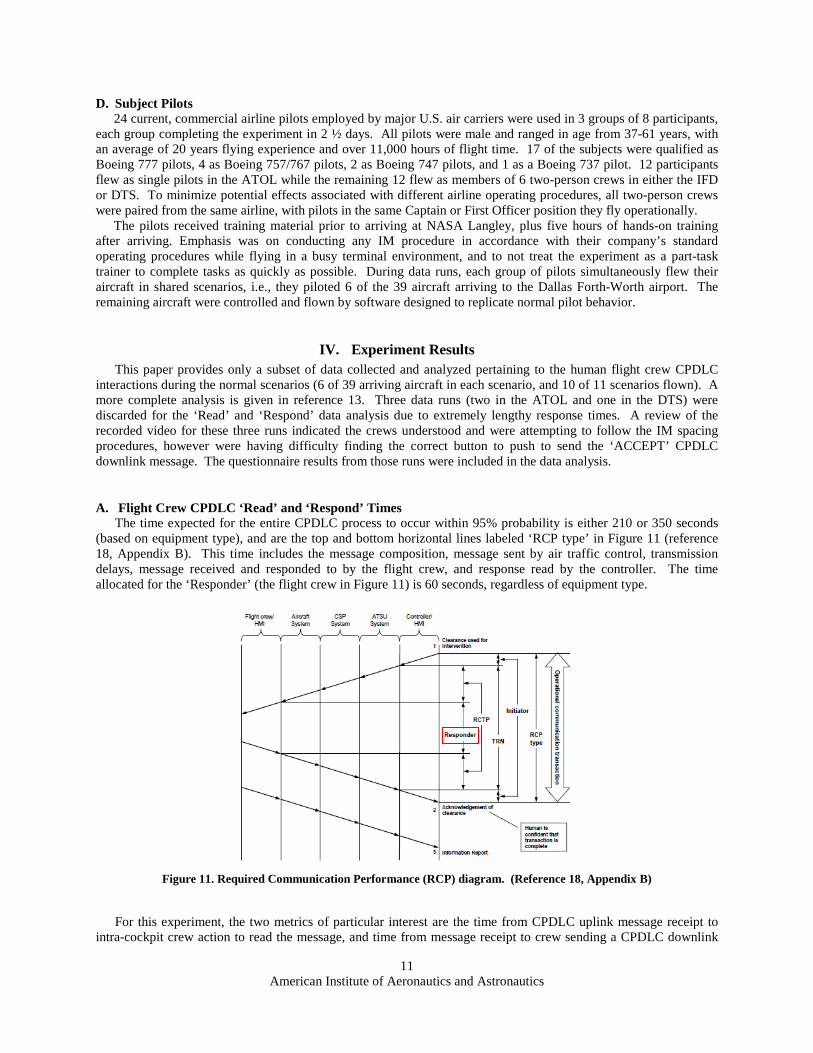
A. Flight Crew CPDLC ‘Read’ and ‘Respond’ Times The time expected for the entire CPDLC process to occur within 95% probability is either 210 or 350 seconds
(based on equipment type), and are the top and bottom horizontal lines labeled ‘RCP type’ in Figure 11 (reference 18, Appendix B). This time includes the message composition, message sent by air traffic control, transmission delays, message received and responded to by the flight crew, and response read by the controller. The time allocated for the ‘Responder’ (the flight crew in Figure 11) is 60 seconds, regardless of equipment type.
Figure 11. Required Communication Performance (RCP) diagram. (Reference 18, Appendix B)
For this experiment, the two metrics of particular interest are the time from CPDLC uplink message receipt to
intra-cockpit crew action to read the message, and time from message receipt to crew sending a CPDLC downlink
American Institute of Aeronautics and Astronautics
12
response as shown earlier in Figure 2. Therefore, the time from the chime simultaneously sounding with the ‘ATC Message’ light illuminating on the EICAS, until the flight crew sent a CPDLC downlink message of ‘ACCEPT’ or ‘REJECT’, is the Required Communication Performance (RCP) time labeled ‘Responder’ and outlined by the red box in Figure 11. None of the three simulators used during the IMSPiDR1 experiment model any of the other systems or categories shown in the RCP diagram.
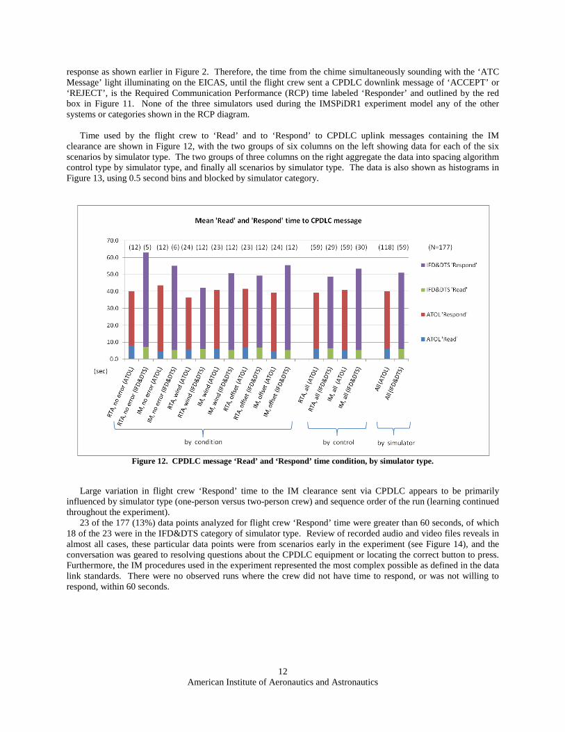
Time used by the flight crew to ‘Read’ and to ‘Respond’ to CPDLC uplink messages containing the IM
clearance are shown in Figure 12, with the two groups of six columns on the left showing data for each of the six scenarios by simulator type. The two groups of three columns on the right aggregate the data into spacing algorithm control type by simulator type, and finally all scenarios by simulator type. The data is also shown as histograms in Figure 13, using 0.5 second bins and blocked by simulator category.
Figure 12. CPDLC message ‘Read’ and ‘Respond’ time condition, by simulator type.
Large variation in flight crew ‘Respond’ time to the IM clearance sent via CPDLC appears to be primarily
influenced by simulator type (one-person versus two-person crew) and sequence order of the run (learning continued throughout the experiment).
23 of the 177 (13%) data points analyzed for flight crew ‘Respond’ time were greater than 60 seconds, of which 18 of the 23 were in the IFD&DTS category of simulator type. Review of recorded audio and video files reveals in almost all cases, these particular data points were from scenarios early in the experiment (see Figure 14), and the conversation was geared to resolving questions about the CPDLC equipment or locating the correct button to press. Furthermore, the IM procedures used in the experiment represented the most complex possible as defined in the data link standards. There were no observed runs where the crew did not have time to respond, or was not willing to respond, within 60 seconds.
American Institute of Aeronautics and Astronautics
13
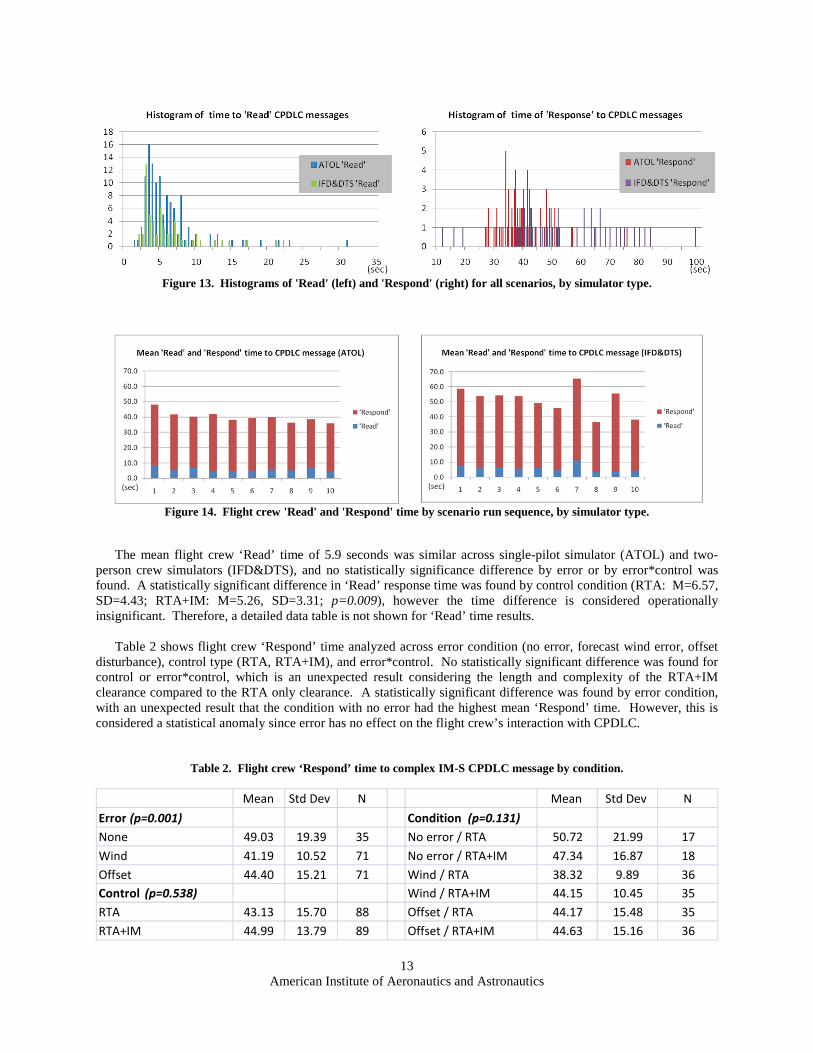
Figure 13. Histograms of 'Read' (left) and 'Respond' (right) for all scenarios, by simulator type.
Figure 14. Flight crew 'Read' and 'Respond' time by scenario run sequence, by simulator type.
The mean flight crew ‘Read’ time of 5.9 seconds was similar across single-pilot simulator (ATOL) and two-
person crew simulators (IFD&DTS), and no statistically significance difference by error or by error*control was found. A statistically significant difference in ‘Read’ response time was found by control condition (RTA: M=6.57, SD=4.43; RTA+IM: M=5.26, SD=3.31; p=0.009), however the time difference is considered operationally insignificant. Therefore, a detailed data table is not shown for ‘Read’ time results.
Table 2 shows flight crew ‘Respond’ time analyzed across error condition (no error, forecast wind error, offset
disturbance), control type (RTA, RTA+IM), and error*control. No statistically significant difference was found for control or error*control, which is an unexpected result considering the length and complexity of the RTA+IM clearance compared to the RTA only clearance. A statistically significant difference was found by error condition, with an unexpected result that the condition with no error had the highest mean ‘Respond’ time. However, this is considered a statistical anomaly since error has no effect on the flight crew’s interaction with CPDLC.
Table 2. Flight crew ‘Respond’ time to complex IM-S CPDLC message by condition.
Mean Std Dev N Mean Std Dev N Error (p=0.001) Condition (p=0.131) None 49.03 19.39 35 No error / RTA 50.72 21.99 17 Wind 41.19 10.52 71 No error / RTA+IM 47.34 16.87 18 Offset 44.40 15.21 71 Wind / RTA 38.32 9.89 36 Control (p=0.538) Wind / RTA+IM 44.15 10.45 35 RTA 43.13 15.70 88 Offset / RTA 44.17 15.48 35 RTA+IM 44.99 13.79 89 Offset / RTA+IM 44.63 15.16 36
American Institute of Aeronautics and Astronautics
14
Table 3 shows flight crew ‘Respond’ time by simulator type (ATOL, IFD&DTS), and was statistically and
operationally significantly different between simulator types. Based on crew debrief comments and research observations, it is postulated the difference is caused by the time required for the two-person crew to verbally brief the CPDLC message to each other, and the use of a mouse to operate the personal computers in the ATOL compared to actual aircraft hardware in the IFD and DTS. Considered much less of a contributing factor were the effect of using the EICAS system for CPDLC (ATOL) versus the MCDU for CPDLC (IFD and DTS), and operating the aircraft in Vertical Navigation Path Mode (VNAV PTH) versus Speed Mode (VNAV SPD) (VNAV PTH shown in Figure 7). Therefore, the conclusion portion of the paper will use ‘Respond’ time from the IFD&DTS simulators.
Table 3. Flight crew ‘Respond’ time to complex IM-S CPDLC message by simulator type.
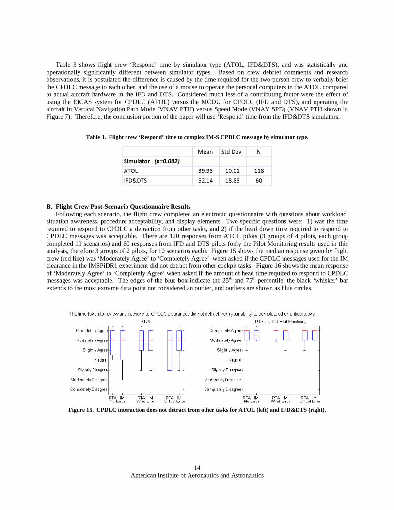
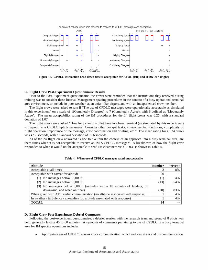
B. Flight Crew Post-Scenario Questionnaire Results Following each scenario, the flight crew completed an electronic questionnaire with questions about workload,
situation awareness, procedure acceptability, and display elements. Two specific questions were: 1) was the time required to respond to CPDLC a detraction from other tasks, and 2) if the head down time required to respond to CPDLC messages was acceptable. There are 120 responses from ATOL pilots (3 groups of 4 pilots, each group completed 10 scenarios) and 60 responses from IFD and DTS pilots (only the Pilot Monitoring results used in this analysis, therefore 3 groups of 2 pilots, for 10 scenarios each). Figure 15 shows the median response given by flight crew (red line) was ‘Moderately Agree’ to ‘Completely Agree’ when asked if the CPDLC messages used for the IM clearance in the IMSPiDR1 experiment did not detract from other cockpit tasks. Figure 16 shows the mean response of ‘Moderately Agree’ to ‘Completely Agree’ when asked if the amount of head time required to respond to CPDLC messages was acceptable. The edges of the blue box indicate the 25th and 75th percentile, the black ‘whisker’ bar extends to the most extreme data point not considered an outlier, and outliers are shown as blue circles.
Figure 15. CPDLC interaction does not detract from other tasks for ATOL (left) and IFD&DTS (right).
Mean Std Dev N Simulator (p=0.002) ATOL 39.95 10.01 118 IFD&DTS 52.14 18.85 60
American Institute of Aeronautics and Astronautics
15
Figure 16. CPDLC interaction head down time is acceptable for ATOL (left) and IFD&DTS (right).
C. Flight Crew Post-Experiment Questionnaire Results Prior to the Post-Experiment questionnaire, the crews were reminded that the instructions they received during
training was to consider these Interval Management spacing procedures in the context of a busy operational terminal area environment, to include in poor weather, at an unfamiliar airport, and with an inexperienced crew member.
The flight crews were asked to rate if “The use of CPDLC messages were operationally acceptable as simulated in this experiment” on a scale of 1(Completely Disagree) to 7 (Completely Agree), with 6 defined as ‘Moderately Agree’. The mean acceptability rating of the IM procedures for the 24 flight crews was 6.25, with a standard deviation of 1.07.
The flight crews were asked “How long should a pilot have in a busy terminal (as simulated by this experiment) to respond to a CPDLC uplink message? Consider other cockpit tasks, environmental conditions, complexity of flight operation, importance of the message, crew coordination and briefing, etc.” The mean rating for all 24 crews was 42.7 seconds, with a standard deviation of 35.6 seconds.
23 of the 24 flight crew answered ‘YES’ to “Within the context of an approach into a busy terminal area, are there times when it is not acceptable to receive an IM-S CPDLC message?” A breakdown of how the flight crew responded to when it would not be acceptable to send IM clearances via CPDLC is shown in Table 4.
Table 4. When use of CPDLC messages rated unacceptable.
Altitude Number Percent Acceptable at all times 2 8% Acceptable with caveat for altitude 20 --
(1) No messages below 18,000ft (1) 4% (2) No messages below 10,000ft (13) 54% (3) No messages below 5,000ft (includes within 10 minutes of landing, on
downwind, and when on final) (20) 83% When given with ATC verbal communication (no altitude associated with response) 1 4% In weather / turbulence / anomalies (no altitude associated with response) 1 4% TOTAL 24 --
D. Flight Crew Post-Experiment Debrief Comments Following the post-experiment questionnaire, a debrief session with the research team and group of 8 pilots was
held, generally lasting 45 to 60 minutes. A synopsis of comments pertaining to use of CPDLC in a busy terminal area for IM spacing operations includes:
• Appropriate use of CPDLC reduces voice communication, which reduces stress and miscommunication.
American Institute of Aeronautics and Astronautics
16
• Use of CPDLC tends to be more acceptable in airspace with all aircraft operating under ATC control (above 18,000’ in the U.S.) and when weather conditions precludes aircraft operating under visual flight rules (poor weather), since flight crew have reduced out-the-window visual scan responsibilities.
• As experience is gained with CPDLC, the workload would decrease further and acceptability should increase.
• The procedure should allow for reloading a CPDLC message into the spacing tool if required. • If the CPDLC equipment is certified to accurately transmit messages from the ground to the aircraft,
and the aircraft avionics are certified to accurately transfer the information from the CPDLC message into the spacing tool, the crews should conduct only a cursory review of the data in the MCDU IM spacing pages. This was estimated to reduce flight crew ‘Respond’ time by 10 seconds.
• The CPDLC interaction required too many button pushes to accomplish the IM procedure. The multiple button pushes, especially when occurring in different locations (for example, the CPDLC pages on one MCDU and IM-S pages on the other), were confusing, time consuming, and the root cause for the three data runs excluded from data analysis. The crews made two suggestions to reduce the number of steps in the IM procedure:
(1) 5-step as implemented: Review, Load, Activate, Accept, Execute (see Figure 2) (2) 4-step recommendation: combine the ‘ACTIVATE’ and ‘EXECUTE’ functionality for the
spacing tool into one button push. (3) 3-step recommendation: if transmission and transfer accuracy can be certified (see comment
above), the ‘LOAD’ button push should auto-load the message into the spacing tool and the spacing tool automatically calculate the speed (Review, Load, Accept). This would also require the ground scheduling software to send a very high rate of operationally acceptable clearances to the crew, and allow for the crew to request a change or terminate the clearance at a later time (currently in the concept of operations document). It was estimated this procedure would probably reduce flight crew ‘Respond’ time by 15 to 30 seconds.
V. Conclusion A human-in-the-loop experiment based on arrival and departure flight operations into the Dallas Forth-Worth
airport was conducted to determine if complex CPDLC messages could be used between ATC and flight crew to conduct Interval Management spacing operations. The experiment was made as operationally realistic and complex as possible, to include arrival traffic into a neighboring airport, voice communication between controllers and all other aircraft, and layered cloud decks for the simulators with out-the-window visual systems. Independent variables included the spacing algorithm calculating the specific speed to meet a time (RTA) or an interval behind a specified lead aircraft (RTA+IM), across scenarios that had no wind error, scenarios with forecast wind error and wind shear, and scenarios requiring an offset (reschedule).
Post-experiment questionnaire results reported the crews found the use of CPDLC for terminal area spacing operations to be acceptable, with time allowed to ‘Respond’ to a complex CPDLC message a mean of 42.7 seconds (standard deviation 36 seconds). 13% of the recorded ‘Respond’ times were greater than the 60 seconds expected by the data link standards, however post-experiment review indicates the length of time was associated with equipment or procedural questions, and not due to heavy crew workload or flight crew hesitation about conducting the IM operation. No statistically and operationally significant difference for CPDLC ‘Respond’ time was found between the RTA and the RTA+IM clearances. Post-scenario questionnaire responses indicate the crew interaction with CPDLC did not detract from other cockpit tasks, and that the amount of head down time required was acceptable. 13 of the 24 subject pilots (54%) stated interacting with CPDLC messages of this below 10,000’ would be unacceptable, and 20 of the 24 pilots (83%) reporting messages below 5000’ would be unacceptable.
Several areas for future research were identified: 1. If the transmission and transfer accuracy of CPDLC messages can be certified, suggested modifications of
the IM procedures by the flight crews should reduce mean ‘Respond’ time to under 30 seconds, and significantly reduce their workload and confusion.
2. Use of controller-pilot voice communication to transmit less complex IM-S clearances (see Appendix).
American Institute of Aeronautics and Astronautics
17
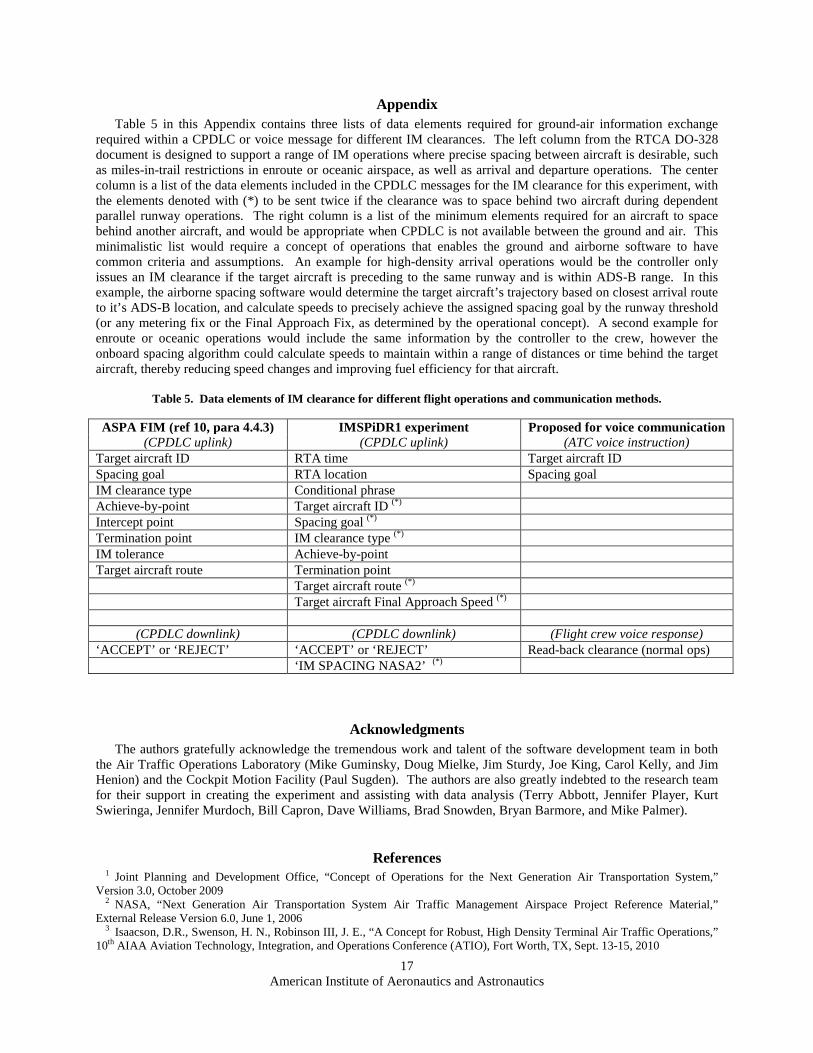
Appendix Table 5 in this Appendix contains three lists of data elements required for ground-air information exchange
required within a CPDLC or voice message for different IM clearances. The left column from the RTCA DO-328 document is designed to support a range of IM operations where precise spacing between aircraft is desirable, such as miles-in-trail restrictions in enroute or oceanic airspace, as well as arrival and departure operations. The center column is a list of the data elements included in the CPDLC messages for the IM clearance for this experiment, with the elements denoted with (*) to be sent twice if the clearance was to space behind two aircraft during dependent parallel runway operations. The right column is a list of the minimum elements required for an aircraft to space behind another aircraft, and would be appropriate when CPDLC is not available between the ground and air. This minimalistic list would require a concept of operations that enables the ground and airborne software to have common criteria and assumptions. An example for high-density arrival operations would be the controller only issues an IM clearance if the target aircraft is preceding to the same runway and is within ADS-B range. In this example, the airborne spacing software would determine the target aircraft’s trajectory based on closest arrival route to it’s ADS-B location, and calculate speeds to precisely achieve the assigned spacing goal by the runway threshold (or any metering fix or the Final Approach Fix, as determined by the operational concept). A second example for enroute or oceanic operations would include the same information by the controller to the crew, however the onboard spacing algorithm could calculate speeds to maintain within a range of distances or time behind the target aircraft, thereby reducing speed changes and improving fuel efficiency for that aircraft.
Table 5. Data elements of IM clearance for different flight operations and communication methods.
ASPA FIM (ref 10, para 4.4.3) IMSPiDR1 experiment Proposed for voice communication (CPDLC uplink) (CPDLC uplink) (ATC voice instruction)
Target aircraft ID RTA time Target aircraft ID Spacing goal RTA location Spacing goal IM clearance type Conditional phrase Achieve-by-point Target aircraft ID (*) Intercept point Spacing goal (*) Termination point IM clearance type (*) IM tolerance Achieve-by-point Target aircraft route Termination point Target aircraft route (*) Target aircraft Final Approach Speed (*)
(CPDLC downlink) (CPDLC downlink) (Flight crew voice response) ‘ACCEPT’ or ‘REJECT’ ‘ACCEPT’ or ‘REJECT’ Read-back clearance (normal ops) ‘IM SPACING NASA2’ (*)
Acknowledgments The authors gratefully acknowledge the tremendous work and talent of the software development team in both
the Air Traffic Operations Laboratory (Mike Guminsky, Doug Mielke, Jim Sturdy, Joe King, Carol Kelly, and Jim Henion) and the Cockpit Motion Facility (Paul Sugden). The authors are also greatly indebted to the research team for their support in creating the experiment and assisting with data analysis (Terry Abbott, Jennifer Player, Kurt Swieringa, Jennifer Murdoch, Bill Capron, Dave Williams, Brad Snowden, Bryan Barmore, and Mike Palmer).
References 1 Joint Planning and Development Office, “Concept of Operations for the Next Generation Air Transportation System,”
Version 3.0, October 2009 2 NASA, “Next Generation Air Transportation System Air Traffic Management Airspace Project Reference Material,”
External Release Version 6.0, June 1, 2006 3 Isaacson, D.R., Swenson, H. N., Robinson III, J. E., “A Concept for Robust, High Density Terminal Air Traffic Operations,”
10th AIAA Aviation Technology, Integration, and Operations Conference (ATIO), Fort Worth, TX, Sept. 13-15, 2010

American Institute of Aeronautics and Astronautics
18
4 Robinson III, J. E., Kamgarpour, M., “Benefits of Continuous Descent Operations in High-Density Terminal Airspace Under Scheduling Constraints,” 10th AIAA Aviation Technology, Integration, and Operations Conference (ATIO), Fort Worth, TX, Sept. 13-15, 2010
5 Thipphavong, J., Mulfinger, D., “Design Considerations for a New Terminal Area Arrival Scheduler,” 10th AIAA Aviation Technology, Integration, and Operations Conference (ATIO), Fort Worth, TX, Sept. 13-15, 2010
6 Murdoch, J. L., Barmore, B. E., Baxley, B. T., Abbott, T. S., Capron, W. R., “Evaluation of an Airborne Spacing Concept to Support Continuous Descent Arrival Operations,” 8th USA/Europe Air Traffic Management Research and Development Seminar (ATM2009), Napa, CA, June 29 – July 2, 2009
7 Barmore, B. E., Abbott, T. S., Capron, W. R., Baxley, B. T., “Simulation Results for Airborne Precision Spacing along Continuous Descent Arrivals,” 8th AIAA Aviation Technology, Integration, and Operations Conference (ATIO), Anchorage, AK, Sept. 14-19, 2008
8 Abbott, T. S., “A Brief History of Airborne Self-Spacing Concepts,” NASA/CR-2009-215695, NASA Langley Research Center, Feb. 2009
9 “Advanced Merging and Spacing Concept of Operations for the NextGen Mid-Term,” Version 1.4, FAA Surveillance and Broadcast Services Program Office, Washington, DC, Sept. 18, 2009
10 “Safety, Performance and Interoperability Requirements Document for Airborne Spacing-Flight Deck Interval Management (ASPA-FIM),” RTCA DO-328, RTCA, Washington, DC, June 22, 2011
11 Barmore, B. E., Baxley, B. T., Abbott, T. S., Capron, W. R., Shay, R. F., Hubbs, C., “A Concept for Airborne Precision Spacing for Dependent Parallel Approaches,” NASA/TM-2011-000000 (in press), NASA Langley Research Center, Hampton, VA 23681
12 “FAA/NASA Research Transition Team (RTT) Plan, Efficient Flows into Congested Airspace (EFICA),” available from FAA HQ, Sept. 30, 2009
13 Swieringa, K., Murdoch, J. L., “Incorporating Human-Centered Design Principles into the Development of an Airborne Spacing Concept,” 11th AIAA Aviation Technology, Integration, and Operations Conference (ATIO), Virginia Beach, VA, Sept. 20-22, 2011
14 Swenson, H.N., Thipphavong, J., Sadovsky, A., Chen, L., Sullivan, C., Martin, L., “Design and Evaluation of the Terminal Area Precision Scheduling and Spacing System,” 9th USA/Europe Air Traffic Management Research and Development Seminar (ATM2011), Berlin, Germany, June 13-16, 2011
15 Callantine, T., Palmer, E., Kupfer, M., “Human-In-The-Loop Simulation Of Trajectory-Based Terminal-Area Operations,” ICAS2010, 27th International Congress of the Aeronautical Sciences, Nice, France, Sept. 19-24, 2010
16 Abbott, T. S., “A Revised Trajectory Algorithm to Support En Route and Terminal Area Self-Spacing Concepts,” NASA/CR-2010-216204, NASA Langley, Hampton, VA, Feb. 2010
17 “Air Traffic Control,” JO 7110.65T, U.S. Department of Transportation, Washington, DC., Feb. 11, 2010 18 “Global Operational Data Link Document (GOLD),” 1st Edition, International Civil Aviation Organization (ICAO), June 14,
2010 19 “Safety and Performance Standard for Air Traffic Data Link Services in Oceanic and Remote Airspace,” DO-306, RTCA,
Washington, DC., Oct. 11, 2007 20 “Flight deck-based Interval Management (FIM) Controller Pilot Data Link Communications (CPDLC) Messages,” draft v1.0,
RTCA SC-214 / EUROCAE WG-78 and RTCA SC-186 / EUROCAE WG-51 Tiger Team, Washington DC., July 15, 2011 21 Mueller, E., “Experimental Evaluation of an Integrated Datalink and Automation-Based Strategic Trajectory Concept,” 7th
AIAA Aviation Technology, Integration, and Operations Conference (ATIO), Belfast, Ireland, Sept. 18-20, 2007 22 Baxley, B. T., Norman, R. M., Ellis, K. K., Latorella, K. A., Comstock, J. R., Adams, C. A., “Use of Data Comm by Flight
Crew in High-Density Terminal Areas,” 10th AIAA Aviation Technology, Integration, and Operations Conference (ATIO), Fort Worth, TX, Sept. 13-15, 2010
23 Peters, M. E., Ballin, M. G., Sakosky, J. S., “A Multi-Operator Simulation for Investigation of Distributed Air Traffic Management Concepts,” 2nd AIAA Aviation Technology, Integration, and Operations Conference (ATIO), Monterey, CA, Aug. 5-8, 2011
24 Keppel, G., “Design and analysis: A researcher’s handbook,” 3rd edition, Prentice Hall, Upper Saddle River, NJ., 1991

![Crew Accommodations - Crew Survival Guide - 29JUL2011[1]](https://static.fdocuments.us/doc/165x107/54f9c32b4a79590b398b479b/crew-accommodations-crew-survival-guide-29jul20111.jpg)