Use-Case Driven, Architecture Centric Inspection for the ... · approach to testing, it has no...
27
P R E S E N T A T I O N International Conference On Software Testing, Analysis & Review DEC 4-8, 2000 • COPENHAGEN, DENMARK Presentation Bio Return to Main Menu T16 Thursday, Dec 7, 2000 Use-Case Driven, Kirstin Kohler, Oliver Laitenberger, Colin Atkinson Paper Architecture Centric Inspection for the Unified Process
Transcript of Use-Case Driven, Architecture Centric Inspection for the ... · approach to testing, it has no...

P R E S E N T A T I O N
International Conference On
Software Testing, Analysis & ReviewDEC 4-8, 2000 • COPENHAGEN, DENMARK
Presentation
Bio
Return to Main Menu T16
Thursday, Dec 7, 2000
Use-Case Driven,
Kirstin Kohler, Oliver Laitenberger, Colin Atkinson
Paper
Architecture Centric Inspectionfor the Unified Process

*OTUJUVU&YQFSJNFOUFMMFT4PGUXBSF&OHJOFFSJOH
'SBVOIPGFS
*&4&
Sauerwiesen 6D-67661 KaiserslauternGermany
Architecture-centric Inspection for theUnified Development Process (UP)
Oliver Laitenberger, Kirstin Kohler, Colin Atkinson
EuroStar ConferenceKopenhagen, December 2000
IESE
Slide 1 / 14
Copyright © Fraunhofer IESE 2000
Kopenhagen, December 2000
Introduction
Characteristics of the UP
Architecture-centricInspection
Outline
Summary
Perspective-basedReading
Inspection in the UP
• The UP has a well-defined approach to testing, but noconsolidated strategy for inspections
• New development processes put new challenges for theinspection method (a product of the 1970s)
Three main questions:
– WHAT should be inspected during a particularinspection?
– HOW should be inspected to achieve a certain level ofcost-effectiveness?
– WHEN should inspections be performed?
Introduction

IESE
Slide 2 / 14
Copyright © Fraunhofer IESE 2000
Kopenhagen, December 2000
Introduction
Characteristics of the UP
Architecture-centricInspection
Outline
Summary
Perspective-basedReading
Inspection in the UP
JUFS
JUFS
JUFSO
JUFSO
Characteristics of the UP
1IBTFT
*ODFQUJPO &MBCPSBUJPO $POTUSVDUJPO 5SBOTJUJPO
*UFSBUJPOT
$PSF8PSLGMPXT
3FRVJSFNFOUT
"OBMZTJT
%FTJHO
*NQMFNFOUBUJPO
5FTU
IESE
Slide 3 / 14
Copyright © Fraunhofer IESE 2000
Kopenhagen, December 2000
Introduction
Characteristics of the UP
Architecture-centricInspection
Outline
Summary
Perspective-basedReading
Inspection in the UP
Characteristics of the UP
• Iterative, incremental development
UseCaseModel
AnalysisModel
DesignModel
Deploy.Model
Impl.Model
TestModel
Next Iteration
Model in iteration n
Addition to the model in iteration n+1
Changes to the model of iteration n initeration n+1

IESE
Slide 4 / 14
Copyright © Fraunhofer IESE 2000
Kopenhagen, December 2000
Introduction
Characteristics of the UP
Architecture-centricInspection
Outline
Summary
Perspective-basedReading
Inspection in the UP
Characteristics of the UP
Use-CaseModel
DesignModel
ImplementationModel
TestModel
System Analyst
Use Case Engineer
Architect
Use-Case Specifier
completeness/consitency of the
model
integrity of use-case realisations
integrity of use-case
realisations
define
priority of use-cases
corectn
ess/co
nsitency
of the
model
Componente Engineer
AnalysisModel
detaile use-cases
integrity of classes and
subsystems
integrity of classes and
subsystems
inte
grity
of c
lass
es a
nd
sub
syst
ems
Test Designer
integrity of the test model
define test-cases
Integration Tester
perform
integration test
System Tester
performsystem test
IESE
Slide 5 / 14
Copyright © Fraunhofer IESE 2000
Kopenhagen, December 2000
Introduction
Characteristics of the UP
Architecture-centricInspection
Outline
Summary
Perspective-basedReading
Inspection in the UP
Architecture-centric Inspection: Idea
• Organizing inspections around architectureal elements (logicalentities) rather than documents (I.e. models, diagrams etc.)
Architecture-centric OrganizationLogical Entity A ... Logical Entity N
Use
-cas
em
odel
Inspection 1/Inspection 2
Inspection 1 Inspection 1
Ana
l.M
odel Inspection 2
Des
ign
Mod
el Inspection 2
Impl
em.
Mod
el Inspection 2
Doc
umen
t-or
ient
ed (
Mod
el-b
ased
)O
rgan
izat
ion
Tes
tM
odel Inspection 2

IESE
Slide 6 / 14
Copyright © Fraunhofer IESE 2000
Kopenhagen, December 2000
Introduction
Characteristics of the UP
Architecture-centricInspection
Outline
Summary
Perspective-basedReading
Inspection in the UP
Implementation
• Determine the logical entities that warrant inspection (e.g.,system, subsystem, component, class).
• Collect the relevant parts of the documentation of the logicalentity (e.g., all relevant UML diagrams).
– If the volume of the documentation to be inspected is toolarge, perform further partitioning.
– If the volume of the documentation to be inspected isappropriate, use the available documentation for organizingthe inspection.
• Organize and run an inspection.
IESE
Slide 7 / 14
Copyright © Fraunhofer IESE 2000
Kopenhagen, December 2000
Introduction
Characteristics of the UP
Architecture-centricInspection
Outline
Summary
Perspective-basedReading
Inspection in the UP
Benefits
• It complements use-case driven development and testing
• It represents a solution for partitioning large documents thatcannot be inspected in a single inspection.
• The set of information that inspectors must scrutinize fordefects is “intellectually manageable” and conceptually whole.
ArchitecturUse cases

IESE
Slide 8 / 14
Copyright © Fraunhofer IESE 2000
Kopenhagen, December 2000
Introduction
Characteristics of the UP
Architecture-centricInspection
Outline
Summary
Perspective-basedReading
Inspection in the UP
Perspective-based Reading Technique: Idea
Provide technical support for defect detection
HOW?Prescriptive guidelinesfor each perspective onwhat to check and how
to perform therequired checks.
⇒ perspective-basedreading scenarios
WHAT?Idea: A document has
high quality if nopotential stakeholderfinds any defect in it.
⇒ A document shouldbe read from various
perspectives.
Perspective-basedReading Technique
IESE
Slide 9 / 14
Copyright © Fraunhofer IESE 2000
Kopenhagen, December 2000
Introduction
Characteristics of the UP
Architecture-centricInspection
Outline
Summary
Perspective-basedReading
Inspection in the UP
Example
• Each worker has his or her own quality needs for thedocumentation of a software entity.
• They are driven by his or her role in the development process:
designer
Test Designer
Use-case Engineer
DesignDocument

IESE
Slide 10 / 14
Copyright © Fraunhofer IESE 2000
Kopenhagen, December 2000
Introduction
Characteristics of the UP
Architecture-centricInspection
Outline
Summary
Perspective-basedReading
Inspection in the UP
Implementation
The ideas behind PBR are implemented in a scenario foreach perspective.
– a procedural description of activities and questions thatguides inspectors through the inspected document
– represented as a set of steps to be followed
– defines what to check and how to perform the check
Activities– Define scenarios for UP workers to support defect detection
– In the scenarios specify the diagrams (instead of the models)that need to be checked from each worker´s perspective
– The diagrams available for inspection depend on your UPimplementation (not completely defined in the UP)
IESE
Slide 11 / 14
Copyright © Fraunhofer IESE 2000
Kopenhagen, December 2000
Introduction
Characteristics of the UP
Architecture-centricInspection
Outline
Summary
Perspective-basedReading
Inspection in the UP
Implementation
What quality factors are interesting?
Full testability of the system
How to extract and examine information?
How to probe the result of instructions?
PBR Scenario
Introduction
Instructions
Questions
Test Designer
Locate the interaction diagrams for the subsystems.Identify the input and output parameters for eachoperation. Define equivalence classes for theseparameters. Use these classes to define test casesto exercise the operations.
Are operation‘s preconditions indicatedto help define input parameters for test-cases?

IESE
Slide 12 / 14
Copyright © Fraunhofer IESE 2000
Kopenhagen, December 2000
Introduction
Characteristics of the UP
Architecture-centricInspection
Outline
Summary
Perspective-basedReading
Inspection in the UP
Integration of Inspections in the UP
Triggering Inspections
• When all information (for the most important perspectives)becomes available
• This means when the latest increment affected by thearchitectural element has been completed
• It is defined though the priority of use cases (which isdetermined in an early iteration together with the architecturaldescription)
IESE
Slide 13 / 14
Copyright © Fraunhofer IESE 2000
Kopenhagen, December 2000
Introduction
Characteristics of the UP
Architecture-centricInspection
Outline
Summary
Perspective-basedReading
Inspection in the UP
Integration of Inspections in the UP
*ODFQUJPO
&MBCPSBUJPO
$POTUSVDUJPO
5SBOTJUJPO
JU
JU
JUO
JUO
*UFSBUJPOT
$PSF8PSLGMPXT
3FRVJSFNFOUT
"OBMZTJT
%FTJHO
*NQMFNFOUBUJPO
5FTU
*OTQFDUJPO
%PDVNFOUBUJPOPGUIFBSDIJUFDUVSBMDPNQPOFOUJTDPNQMFUF

IESE
Slide 14 / 14
Copyright © Fraunhofer IESE 2000
Kopenhagen, December 2000
Introduction
Characteristics of the UP
Architecture-centricInspection
Outline
Summary
Perspective-basedReading
Inspection in the UP
Summary
• Object-Orientation and the UP raise some new inspectionissues
– WHAT should be inspected during a particular inspection?
– HOW should be inspected to achieve a certain level of cost-effectiveness?
– WHEN should inspections be performed?
• Solutions to these questions are– the architecture-centric inspection approach and
– the perspective based reading technique

1
Architecture-centric Inspection for the Unified Development Process (UP)
Oliver Laitenberger, Kirstin Kohler, Colin Atkinson
Fraunhofer Institute for Experimental Software Engineering
Sauerwiesen 6 D-67661 Kaiserslautern
Germany Tel. +49 6301 707 223 Fax. +49 6301 707 200
Oliver.Laitenberger, Kirstin.Kohler, [email protected]
Abstract: The Unified Process (UP) is expected to become one of the leading methods for software engineering with the UML, but although it has a well-defined approach to testing, it has no consolidated strategy for inspection. This paper addresses this problem by describing how the latest inspection technologies can be integrated with the UP in a way that provides an optimal synergy with testing, and remains faithful to the UP's philosophy of incremental, use-case driven development.
1. Introduction The publication of the Unified Modeling Language (UML) in 1997 has generated a tremendous interest in the use of visual modeling in the development of software systems. However, since the UML only provides a modeling notation, it can be applied in a potentially infinite number of ways for the description of a given software system. Hence, the use of the notation needs to be supported by a UML-oriented development process that helps developers decide which UML diagrams to create and what information the diagrams should contain. Of the various UML-oriented processes that have been published to date, the Unified Process (UP) [9] [11] is likely to be one of the most widely used since it was developed by the UML's leading designers.
The greater the role of UML models in a software development project, the greater their effect on the quality of the final product. Therefore, ensuring the quality of UML artifacts is becoming an increasingly important issue as the notation plays an ever-increasing role in the software industry. However, in contrast with code, which until recently was the main concrete representation of software used in typical projects, UML models (with the possible exception of statecharts) are not directly executable. Other approaches must therefore be used to ensure their consistency with each other and with respect to external constraints (most notably the user requirements). One of the most cost-effective ways of checking the quality of non-executable software artifacts is software inspection. Since the introduction of the notion of inspection to the software domain in the early 1970s [6], it has evolved into one of the most successful methods for early defect detection and removal [2][16]. Its proponents claim that inspections can lead to the detection and correction of anywhere between 50 and 90 percent of defects [7]. Surprisingly, however, the Unified Process (UP) provides very little information or guidance on the application of inspections, despite the fact that it advocates the creation of a relatively large number of models and diagrams. In fact, the main UP reference [9] contains a complete chapter on testing, but no consolidated block of information on how to set up and run inspections.
One possible reason why leading object-oriented development methods, such as the UP, lack comprehensive inspection technology is the assumption that all important inspection problems have essentially been solved, and that traditional approaches are therefore easily applicable to new development paradigms and methods. In other words, the assumption is that provided the constraints on a development artifact are clearly defined, inspection is just the simple and mechanical job of checking them. However, nothing could be further from the truth. As will be explained in this paper, object-oriented methods in general, and the UP in particular, present fundamental new challenges for the inspection method which go right to the heart of how inspections are performed and what role they play. As P. Johnson puts it "Inspection is a product of the mid-

2
1970s - a precursor to the Internet, computer-supported cooperative work technologies, the World-Wide Web, geographically distributed development groups, and virtual organizations" [10].
The cost-effective use of inspections in the context of any development approach presents two fundamental problems –
The first is the collection and organization of the appropriate amount of information for a given inspection. Simply "inspecting" every single artifact defined by a method on an individual basis is impractical (if not impossible) not only because of the shear number of such artifacts, but because of the lack of sufficient context information from which to judge them. The challenge is to find the optimal "critical mass" of information that will allow inspectors to make informed and dependable judgements about artifact quality.
The second problem is the cost-effective enactment of an inspection in such a way as to generate useful and dependable results. Every software development project has limited resources, so those available for software inspection must be applied in a manner that is likely to yield the best return on investment, and maximize the chances of successful defect detection.
Both these issues present particular challenges in connection with the UP. The mere fact that the UP is an object-oriented method, which at its core is built upon the concepts of objects, classes, inheritance, and polymorphism, already presents significant additional challenges in comparison with traditional methods. First, the realization of a given aspect of functionality in an object-oriented approach is typically distributed among many more smaller software elements (i.e., methods) than in traditional structured development approaches, and the definition of these methods is often spread over several modules (due to inheritance). This makes the definition of a suitable critical mass of information that can be inspected effectively in a single inspection extremely difficult. Letovsky and Soloway [17] already observed a similar characteristic in large, functional code units. They reported that distributed information, which they referred to as "delocalized plans", makes functional program code difficult to understand (and, thus, to inspect). The delocalization effect is even worse with visual modeling during object-oriented analysis and design, because information is usually further distributed amongst different diagram types and viewpoints.
The other, more practical, problem faced in the introduction of inspections with object technology is that since the object paradigm represents such a fundamental shift from traditional approaches, companies moving to this paradigm completely change the way in which they produce software. This means that they discard most of their existing development experience and start afresh. The changes present a major challenge for inspection enactment because it means that software developers often do not know what to look for and how to perform the defect detection activity. As pointed out in the literature [16], development experience is considered an important influential factor for the defect detection effectiveness in inspection. Again, this problem is exacerbated when a general puprose method, like the UP, is introduced (as opposed to merely object-oriented programming) since developers are faced with an even greater paradigm shift.
These problems arise from the fact that the UP is a full life-cycle object-oriented development approach, and would be faced whatever method were used to apply the UML in a software development project. However, the UP has some problematic features that are not generally present in other UML-oriented development methods. The first problem stems from the fact that the UP equivocates about the role of UML diagrams (as opposed to models) in the development process. Whereas models represent logical collections of data expressed in terms of UML concepts (i.e. concepts defined in the UML semantics document), diagrams provide the graphical means of rendering this data in an inspectable form1. Therefore, a full definition of both the diagrams and the models to be developed in a project is necessary to provide a fully concrete definition of an inspection process. Unfortunately, however, the UP only explains the role of the latter, and gives very little if any information about the former.
The second problem stems from the highly iterative and incremental nature of the UP, and more importantly from the way in which these increments are driven. Iterations in the UP are mini-projects that each lead to the creation of a new set of artifacts making up a new increment of the final system. Successive iterations typically build on specific artifacts from the state at which they were left at the end of the previous iteration. A major question, therefore, is to determine how much of each artifact to inspect each time through the iteration process. This problem is exacerbated in the UP because it employs a use-case driven approach to the definition of the increments. This means that the additional information added in each increment represents a functional slice through the eventual

3
software system, whereas the architecture of the software is object-oriented. The increment slices are therefore orthogonal to the architectural artifacts.
The basic challenge addressed in this paper, therefore, is to find solutions to the "inspection organization" and the "inspection enactment" problems that take into account the specific problems raised by the UP. This will involve not only the definition of a strategy for coping with the delocalization of information present in all object-oriented projects, but also for addressing the role of diagrams, and the use-case driven nature of the development increments. In this paper we describe a new strategy for selecting sets of inspection artifacts, known as the architecture-centric inspection approach, and describe an advanced strategy for optimizing the examination of this information known as the perspective-based reading technique (PBR). Both approaches are integrated and tailored to the idiosyncrasies of the UP.
The paper is structured as follows: Chapter 2 describes the essential elements of the UP, and provides a more detailed discussion of the inspection-related problems raised by the UP. Chapter 3 then introduces the architecture-centric inspection approach and the perspective-based reading technique. Chapter 4 then describes how these can be used together to provide an effective approach to inspections within the UP. Chapter 5 finally concludes.
2. Overview of the Unified Process The Unified Process (UP) defines a "process framework" for different kinds of software systems, domains, and organisations. The main characteristics of this process are that it is "use-case driven" and "architecture centric", while at the same time defining iterative and incremental process phases. The overall UP development life-cycle is divided into four main phases (inception, elaboration, construction and transition) and consists of a sequence of iterations. The definition of the phases reflects the main focus of the iterations each conducted at certain stages of product development. • The goal of the inception phase to develop a "good idea" into a vision of the end product. The
major deliverables of this phase are an outline of the candidate architecture, a list of identified risks and a “proof-of-concept” prototype.
• During the elaboration phase about 80% of the functional requirements are specified, a stable architecture is designed, and a project plan is established.
• The purpose of the construction phase is to develop the software product, which is ready to be exposed to the customer during a beta release. During this phase, the remaining software components are implemented and the features of the software system are tested.
• During the transition phase beta tests are executed, users are trained and the software is given to the end users. At the end of this phase the product is fully released.
PhasesPhasesPhasesPhases
InceptionInceptionInceptionInception ElaborationElaborationElaborationElaboration ConstructionConstructionConstructionConstruction TransitionTransitionTransitionTransition
iteriteriteriter....#1#1#1#1
iteriteriteriter....#2#2#2#2 ------------
iteriteriteriter....####n-1n-1n-1n-1
iteriteriteriter....####nnnn------------ ------------ ------------------------
IterationsIterationsIterationsIterations
CoreCoreCoreCore W orkflow sW orkflow sW orkflow sW orkflow s
Requirem entsRequirem entsRequirem entsRequirem ents
A nalysisA nalysisA nalysisA nalysis
D esignD esignD esignD esign
Im plem entationIm plem entationIm plem entationIm plem entation
TestTestTestTest
Figure 1: Core workflows and their emphasis shifts over development iterations
4
Figure 1 illustrates the relationship between activities, phases and iterations in the UP. Workflows, similar to the ones in classical software development approaches, are shown on the vertical axis. These include requirements, analysis, design, implementation and test. The horizontal axis represents the different phases and their iterations. While each iteration includes all described workflow activities, the emphasis of one iteration shifts according to the phase. This means that during the inception and elaboration phase most effort is put into the definition of requirements. The construction phase, on the other hand, requires more effort on implementation and testing. Different artifacts are created at different points in a UP development project. One of the most important artifacts from the perspective of inspection is the "model" which represents a semantically closed abstraction of the system. A model can be regarded as a self-contained description of the system that provides a complete picture of its properties from a certain perspective to support specific workers. As well as higher level models, such as the business model, the UP defines the use-case model, analysis model, design model, deployment model, implementation model, and test model. • The use-case model represents the system’s intended functions and environment. It is used as
a means of communication between customers and developers. The use-case representation of the system contains actors, use-cases, and their relationships.
• The analysis model provides an overview of the expected system functionality, but avoids details of how the system actually works. The analysis model consists of classes and interaction diagrams illustrating the realisation of use-cases.
• In the design model, the analysis model is adapted to a selected implementation environment, like CORBA, the GUI construction kit, etc. The design model encompasses all design classes, subsystems, packages, collaborations, and relationships between them.
• The implementation model primarily contains the code for the software system. • The test model consists of information relevant for performing testing during the various
phases. It is a collection of test-cases, test procedures, and components. During the course of a development project, these models are built incrementally. This means that in successive iterations more detail is gradually added to the models through refinement and translation. Another very important artifact in the UP is the architectural description of the system [11]. It is essentially orthogonal to the models just described. The architectural description provides a view of the system that combines "slices" of the different models most relevant for the architecture. This means the architectural view contains those use-cases of the use-case model that are critical for the architecture, the architecturally most important classes and subsystems of the design model and so on. Most parts of the architectural description are finalised at the end of the elaboration phase and do not change significantly during subsequent phases. In this way, the architectural description describes the structural elements and their interfaces together with their behaviour as embodied in their collaboration. Models in the UP are essentially logical artifacts, and thus do not have a tangible representation per se. In other words, models themselves are not directly visible. To make models tangible, the UML (and thus the UP) uses diagrams. A diagram is a development artifact that provides a concrete rendering of UML model elements in a graphical form. However, the description of the UP gives no precise explanation of what role diagrams are expected to play in a development project, or how models and diagrams are related. The most useful interpretation (consistent with the UP) seems to be that a diagram provides a window onto a model. In other words, as illustrated in Figure 2, a diagram serves to provide a physical, graphical rendering of a subset of the model elements within a model. Of course, the subset can be the whole set (i.e., the diagrams cover the whole model).

5
Figure 2: Diagrams provide a window onto models
For the development of the various artifacts, the UP describes a number of roles. These roles each have defined responsibilities and contribute to the overall product development by defining a specific kind of artifact (i.e. part of a model).
2.1 Inspection Issues in the Unified Process In the current description of the UP [9][12] very little information can be found on how to perform inspections. This may lead to the conclusion that traditional software inspection methods, such as the one described in [7], can be used unchanged in the context of the UP. However, as we already pointed out at the beginning of the paper, the UP presents additional challenges for the successful application of inspections. Since we have now described the most important ingredients of the UP, we can elaborate upon these issues in more detail. We start with the problems related to the organization of an inspection.
Because the UP is inherently incremental and iterative, the main question that arises with respect to inspections is when in the process they should be performed. Should it be at the end of the main phases or within one of the iterations? This decision pretty much influences the determination of the documentation to be inspected. Classical inspection approaches usually focus on one particular type of documents like requirements-, design- or code-documents. How does this fit to the UP? A complete design document (in the context of UP the design model) will not be finished before the construction phase starts, so this question is not an easy one to answer.
Assuming that the point in time (or iteration) at which the inspection should be performed is known, the set of information to be inspected (i.e., an optimal unit for inspection) in one particular inspection still needs to be determined. This raises two issues: 1. Successive iterations build on the artifacts from the state at which they were left at the end of the
previous iteration. However, once the artifact has been inspected in one iteration, how much of the artifact needs to be inspected in the next iteration? One should also take into account, that at the end of each iteration a test phase is executed that focuses on the use-cases added in that iteration. To make the inspection cost effective, the inspection should concentrate on a complementary set of defects, which are not likely to be found during the test phase. At the same time, each iteration not only adds new information but also changes or extends a lot of the existing diagrams and classes. By changing them it is likely that inconsistencies within classes and subsystems are introduced. Picking the right unit for inspection might be focused on a paticular type of defects or on compensating for inconsitencies to previous iterations.
The second difficulty in defining the right set of information to inspect arises from the fact
that information added in one iterration is distributed over all models (as shown in 2. Figure 3). This shows how subsequent iterations add new information to the models (indicated in
red) and changes/extends existing information (indicated in red and green). Moreover, within a
Model
Diagram A
Diagram B
Diagram C

6
given model, information is often further distributed among different diagram types. For example the analysis model might consist of collaboration diagrams, class diagrams, and package diagrams. At the same time, different diagram type are even used in several models. For example, collaboration diagrams are part of the analysis model as well as of the design model. The question thus arises as to whether individual diagrams should be inspected or whether models should be inspected. Some policy is required for deciding what exactly to examine during a particular iteration of the inspection process.
Thus, the single biggest challenge in applying inspection technology to a UML-oriented process, such as the UP, is the collection and organization of a "critical mass" of information for a given inspection. As pointed out by [4], if critical information is missing, inspectors tend to make unwarranted assumptions (even if unintentionally) which can undermine the effectiveness of the inspection. In fact, it can even be worse than performing no inspection at all, since a faulty inspection can lead to unwarranted confidence about the quality of the software artifact.
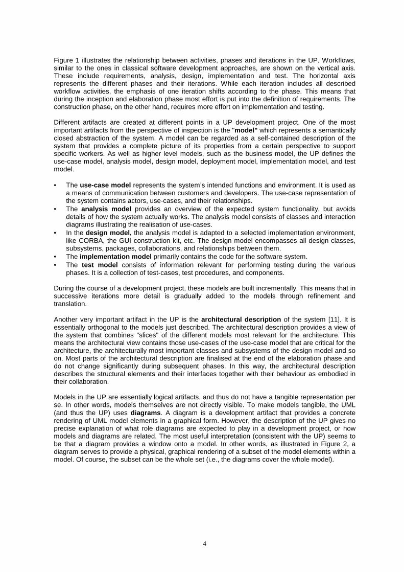
Figure 3: Information accumulation in successive iterations When large companies move to the UP, they often completely change the way they produce software. This means that they discard most of their existing development experience and start from scratch. In the UP, for example, at least ten different roles are defined. Each of these roles has a very narrow view of the system. A person with a specific role performs the associated role-specific tasks and is responsible for a certain set of quality aspects. Figure 4 illustrates only a subset of the roles, responsibilities, and the relationships in the UP. The arrows indicate the contribution of different people to the different models. From Figure 4 it is easy to see that the dependencies between workers and models are very complex, making it difficult for inspectors to cover all important quality issues of the various artifacts. Inspectors inexperienced in the UP often do not know what to look for and how to perform defect detection on UP development artifacts. In particular, they do not know which parts of the information to concentrate and how to link information spread over the various models. As pointed out several times in the literature [16], development experience is considered an important influential factor for the defect detection effectiveness in inspection. To compensate for the lack of experience, defect detection or reading techniques [1] specifically tailored to the UP process are required that support inspectors in their defect detection task. These reading technique have to consider the various roles, responsibilities and tasks described in the process.
Use CaseModel
AnalysisModel
DesignModel
Deploy.Model
Impl.Model
Test Model
Next Iteration
Model in iteration n
Addition to the model in iteration n+1
Changes to the model of iteration n in iteration n+1
7
Figure 4: Usage of various models by different roles
3. Architecture-centric and Perspective-based Inspections In the previous section we provided an overview of the salient features of the UP and described the main challenges that it presents from the perspective of inspections. Before we describe our recommended solution to these problems, in this section we describe the two inspection technologies upon which our solution is based. The approaches will first be presented in a general way, and then in the following subsection their optimal use in the context of the UP will be explained.
3.1 Architecture-centric Inspection Organization As mentioned in the previous sections, the first major challenge to be addressed in a modern inspe ction program is identifying the appropriate collection of information to examine in an individual inspection. Traditional inspection approaches use the document-type strategy as a guiding principle for making this judgment. This means that an inspection is centered around a particular document type (e.g. requirements document, design document or code document). In the context of graphical modeling, a document can be interpreted as an explicit modeling product such as a model or a diagram. Taking a document-oriented approach to inspection therefore means that an individual inspection is oriented towrads the examination of an individual artifact, such as a requirements document, a code document, a UML model or a UML diagram.
Use-CaseModel
DesignModel
ImplementationModel
TestModel
System Analyst
Use Case Engineer
Architect
Use-Case Specifier
completeness/consitency of the
model
integrity of use-case realisations
integrity of use-case
realisations
define priority of
use-cases
corectness/
consitency
of the
model
Componente Engineer
AnalysisModel
detail use-cases
integrity of classes and
subsystems
integrity of classes and
subsystems
integ
rity o
f clas
ses a
nd
subs
yste
ms
Test Designer
integrity of the test model
define test-cases
Integration Tester
perform
integration test
System Tester
performsystem test

8
Although at first sight the document-oriented approach seems represent a reasonable strategy fro organizing an insepction, on closer examination this turns out not to be the case. The problem is that in more modern development methods, information is highly distributed across different documents or even across different document types. For example, the UP uses different types of models to provides distinct viewpoints of a system, and different kinds of diagrams to render these models. Thus, if the inspection is limited to a particular (part of a) document, an inspector may miss crucial information for a sound inspection. A particular model (or viewpoint) only provides a very limited view of the software system, so information from various models need to be combined to provide the inspector with sufficient context information for a meaningful inspection. Simply choosing to inspect a given document or model therefore is too simplistic for significantly sized systems.
Figure 5: Logical Entities and their Documentation
A more powerful strategy described by [14] is to organize individual inspections around logical entities making up the software system rather than specific artifacts documenting the system. This approach is illustrated in Figure 5. In this figure, triangles represent logical entities, such as uses cases, classes, attributes, packages etc., while squares represent documentation artifacts, such as use-case diagrams, requirements documents, design documents, code, etc. There is a line between a documentation artifact and a logical entity when the former contains information about the latter. Thus, Figure 5 illustrates the usual situation in modern development methods where there is an m:n relationship between documentation artifacts and logical entities. Instead of organizing an individual inspection around the documentation (i.e., a square), a more powerful approach is to organize an individual inspection around an individual logical artifact (e.g., a triangle). The information examined in an inspection therefore represents a slice across the various documentation artifacts describing the logical entity. In other words, the choice of the logical entity determines the document fragments containing relevant information to be scrutinized in one particular inspection. Since, in a general sense, the logical entities making up a system are typically viewed as capturing its architecture, this approach is termed the architecture centric approach to inspection organization. Precisely what logical entities actually make up the software architecture, and thus represent good candidates for units of inspection, depends on the nature of the development method. This will be discussed in the context of the UP in the next section. Table 1 contrasts the two different approaches for inspection organization in the context of the UP.

9
Architecture-centric Organization Logical Entity A ... Logical Entity N
Use
-cas
e M
odel
Inspection 1/ Inspection 2
Inspection 1
Inspection 1
Anal
. M
odel
Inspection 2
D
esig
n M
odel
Inspection 2
Impl
em.
Mod
el
Inspection 2
Doc
umen
t-orie
nted
(Mod
el-b
ased
) O
rgan
izat
ion
Test
M
odel
Inspection 2
Table 1: Document-oriented versus architecture-centric inspection organization Inspection 1 is organized according to the more classical document-oriented approach. The unit of inspection in Inspection 1 is the set of diagrams in the use-case model (i.e. the use-case and sequence diagrams). In this case, no concern is given to which of the logical entities is involved. The inspection is simply focused on the examination of the information included in this model. Contextual information that may be available in diagrams of other models, such as class diagrams in the analysis model, is not provided. This means that an inspector must either obtain this information separately, which adds to the costs of inspection 1, or is in danger of missing subtle defects. Inspection 2, on the other hand, is organized according to logical entities (logical entity A). Inspectors receive all the information about entity A from all the models that are currently available. The analysis of the provided information allows the inspectors to achieve a complete and coherent impression of the inspected entity. This is beneficial for two reasons. First, inspectors do not have to spend extra effort for information retrieval. Second, the issue of delocalized information, which is particularly relevant for object-oriented projects, is addressed. This stems from the fact that an inspector receives enough information for a sound inspection. This very small example highlights the differences between the two approaches. In the next section we explain in more detail how to instantiate the architecture-centric principle in the context of UP inspections.
3.2 Perspective-based Defect Detection Support Defining what information should be examined within an individual inspection is only part of the problem however. The other major problem to be addressed is how the information should actually be checked or read. Traditionally, industrial inspection implementations use either no specific reading approach (often termed ad-hoc) or checklist-based reading (CBR) during defect detection. Ad-hoc reading, as its name implies, provides no explicit advice for inspectors as to how to proceed, or what specifically to look for, during the reading activity. Hence, the results of the reading activity in terms of potential defects or problem spots are fully dependent on human experience and expertise.

10
Checklists offer stronger support mainly in the form of yes/no-questions that inspectors need to answer while reading a software document. Gilb and Grahams' manuscript on software inspection states that checklist questions interpret specified rules within a project or an organization. Although a checklist provides advice about what to look for in an inspection, it does not describe how to identify the necessary information and how to perform the required checks. Moreover, for CBR as well as for ad-hoc it remains unclear as to what degree a systematic reading process has been applied. Recently, Victor Basili proposed scenario-based reading to offer more procedural support for defect detection [1]. The basic idea of a scenario-based reading technique is the use of so-called scenarios to provide algorithmic guidelines on how to go about finding the required information in a software document and what that information should look like. Hence, a scenario-based approach is more prescriptive than either the ad-hoc or the checklist-based technique. A particular promising scenario-based reading technique is perspective-based reading.
3.2.1 Perspective-based Reading The basic goal of PBR is to examine the documentation of a logical entity from the perspectives of the entity’s various stakeholders [13]. An inspector using PBR therefore reads the documentation from the perspective of a particular stakeholder in such a way as to determine whether it satisfies the stakeholders’ particular needs. A stakeholder perspective may be, for example, a future user of the system who wants to ensure the completeness of the inspected analysis documents. If the documentation of the entity meets the stakeholders’ quality requirements, the end product (i.e. the final software system) will meet the specified quality goals.
3.2.2 Perspective-based Reading Scenarios During the reading process, an inspector follows the instructions of a perspective-based reading scenario (in short: scenario). A scenario tells the inspector how to go about reading the documentation from one particular perspective and what to look for. A scenario consists of an introduction, instructions, and questions framed together in a procedural manner. The introductory part describes the worker's interest in the logical entity and explains the quality factors most relevant for this perspective. The instruction part describes what parts of what documents an inspector is to use, how to read those parts, and how to extract the appropriate information from them. While identifying, reading, and extracting information, inspectors may already detect some defects. However, the motivation for providing guidance for inspectors on how to perform the reading activity is three-fold. First, the instructions help an inspector gain a focused understanding of the entity. Understanding involves the assignment of meaning to information in a particular set of document parts and is a necessary prerequisite for detecting more subtle defects2. Second, the instructions require an inspector to actively work with the documentation rather than passively scanning it. Third, the architecture-centric strategy ensures that the relevant information is available for scrutiny. However, since the attention of an inspector is focused on the information most interesting for a particular stakeholder, the inspector is not swamped with details irrelevant for the stakeholder's perspective. A process for scenario development is described in [13]. Once an inspector has achieved an understanding of the documented information related to the logical entity, he or she can examine and judge whether this documentation fulfils the required quality properties. For making this judgement an inspector is supported by a set of questions that are answered while following the instructions.
4. Software Inspections in the UP This section presents a general approach for the cost-effective use of inspections in the UP. It first discusses how the architecture-centric and perspective-based approaches relate individually to the UP, and then describes an optimal synergy which integrates them with the UP philosophy of use-case driven, incremental development.
4.1 Architecture-centric Inspection Organization in the UP The first problem that arises when considering architecture-centric inspection in the context of the UP is the meaning of the term "architecture", and more importantly, the logical entities of which the architecture is comprised. In the work on architecture-centric inspection [14], any logical entity (as opposed to documentation artifact) in the system can be taken as an architectural component suitable for serving as the focus of an inspection. In modern methods this includes functional
11
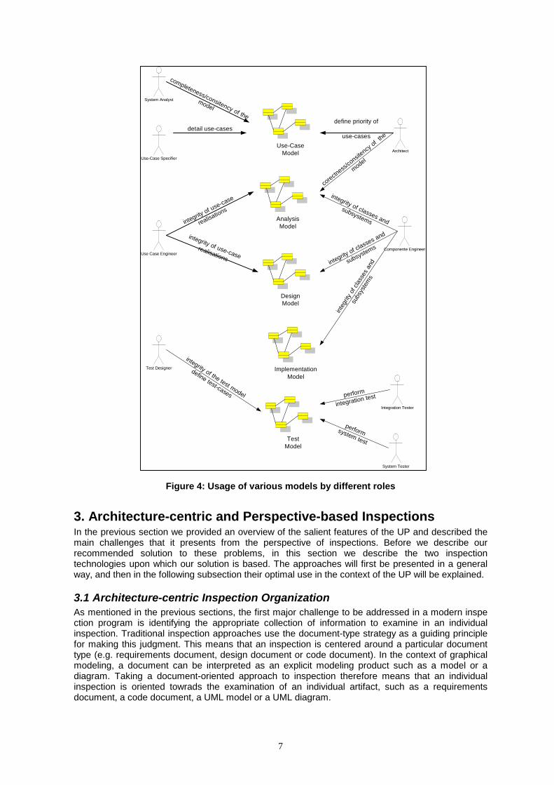
abstractions, such as use-cases and methods as well as data-oriented abstractions such as classes, objects, and subsystems etc. Since the UP is use-case driven, meaning that use-cases are the basis for organizing the independent development iterations, at first sight it might apear that the optimal approach would be to adopt use-cases as the logical entities upon which to base individual inspections (for architecture-centric inspection). This approach, illustrated in Figure 6, has the appeal that the performance of inspections would appear to be "in sync" with individual development iterations, since it would call for the inspection of the result of an iteration (i.e., use-case oriented increment) at the end of the iteration. Thus, an inspection would be performed at the end of each iteration of the project, and would examine the results of that increment. In short, inspections would concide exactly with increments.
Subsystem A Subsystem NUse Case A
Use Case N
….
….
I1 I1
Im Im
Figure 6: Use-cases as inspection units
Although this symmetry has a primae face appeal, on closer analysis it turns out not be the optimal approach. There are two reasons for this.
The first is that it leads to a situation in which the inspections performed in each increment are focusing on the same set of information as the test performed in that increment, namely the new software corresponding to the "driving" use-case. Although this would still be valuable from a theoretical perspective, since inspections have been proven to uncover defects not normally detected in testing, it does not represent a good solution from a resource management point of view. This is because, with limited resources, quality assurance effort needs to be allocated in a way that optimizes the detection of defects, and generally speaking the overall effectiveness is increased the more "orthogonal" inspections and testing become.
The second problem is that when inspections are increment-oriented, the problem of regression arises. It is clearly undesirable in one iteration to reinspect all parts of an artifact that have just been inspected in the previous iteration. However, some overlap is necessary to check consistency of the new increment with the existing parts. The problem is similar to that faced in testing, but with one major difference. Whereas regression testing relies heavily on automation to retest elements of the software likely to have been affected by a new increment, the same techniques are not generally applicable with inspections. This is because inspection is by definition a manual activity, and reexamining an already inspected artifact very rapidly leads to inspector fatigue.
A much greater synergy is achieved between the testing and inspection aspects of quality assurance if inspection is organized according to the elements of the architecture (in the UP sense of "architecture") rather than use-case (see Figure 7). In other words, inspections provide a greater complement to tests if the units of inspection are taken to be UP architectural artifacts, such as subsystems, classes, objects etc, rather than use-cases (which drive the increments). This has the major advantage that inspections are orthogonal to tests, and the regression-inspection problem is significantly reduced. It also has the minor advantage that the uses of the term "architecture" in the sense architecture-centric inspection and in the sense of the UP coincide.

12
Subsystem A Subsystem N UseCase A
UseCase N
….
….
I1 Im
I1 Im Figure 7: UP Architectural elements as units of inspection
4.2 Perspective-based Reading in the UP Once the logical entities that will form the units of individual inspections have been determined it is usually a straightforward task to extend the inspection approach to support perspective-based reading. All that is normally required is to define scenarios that tell the inspector how to identify the documentation fragments containing relevant information about the unit of inspection. Unfortunately, this task is not so straightforward with the UP because it is unspecific about the role of diagrams. Although the UP defines the various models to be created in a project, it says nothing about the diagrams that should be used to render them. Diagrams are important because they provide the only physically inspectable manifestation of models3. Since the UML provides no concrete rules about diagrams to be created, there are essentially two strategies that can be adopted.
The first approach assumes a minimal number of diagrams sufficient to capture all the information contained in the models. In other words, all the information in a model is rendered in at least one diagram, and the overlap between diagrams is minimal. Thus, the structural aspects of a model (if it has any) would be captured in a single class diagram, the behavioral aspects (if it has any) in a single statechart diagram and so on. The basic idea is that the diagrams represent a minimal embodiment of a model.
Since a diagram can be thought of as providing a window onto a subset of information in a model, and these windows are not specified by the UP, an alternative approach is to define diagrams which provide precisely the information needed for particular perspective in an inspection. In other words, instead of using a minimal set of diagrams to render the information in a model, diagrams could be used that provide an optimal presentation of information for perspective-based inspection. These diagrams could be created manually as part as an inspection-enhanced UP, or they could be created automatically by an inspection-enhanced tool capable of filtering out from a model the information necessary to inspect a logical artifact from a given perspective.
The distinction between these two approaches is quite subtle. In the first case, an inspector would have to identify subsets of information within UML diagrams relevant for the inspection of a logical artifact from a given perspective, while in the second case the inspector simply has to identify the diagrams providing the relevant information. The difference therefore essentially involves a different way of distributing information within UML diagrams. The first approach is based on a flat "system-wide" distribution of information, while the second is based on a more component-oriented distribution organized around the logical entities. Thus a component-oriented organization of diagrams, such as that defined in KobrA [4], provides more direct support for architecture-centric, perspective-based inspections of the kind discussed in this paper. The other main question that needs to be addressed when using perspective-based inspections is which stakeholders should be chosen as inspection perspectives. When applying PBI within the context of a general purpose method, the ideal situation is that the main roles (or workers in UP terminology) are taken to be the perspectives. As mentioned in section 2, the UP defines several different kinds of workers at different levels of abstraction, but at the system level, the following workers are important: User, system analyst, use-case specifier, architect, test designer, and component engineer. Hence, an inspection whose goal is to assure the quality of the system should ideally involve at least five inspectors, each of whom scrutinizes the appropriate diagrams (or subsets thereof) from a specific worker’s perspective. An example is the perspective of the tester worker. The tester is responsible for executing the tests including:

13
• Test set-up and execution
• Evaluation of test execution and recovery from errors
• Assessing the results of test and logging identified defects Thus, an inspector reading from the perspective of a tester needs to ensure that the worker can perform these tasks based on the relevant diagrams. Since testing is focused on the functionality and behavior of the logical entity, this means the relevant UML diagrams are the interaction diagrams describing the realization of each individual method, and the statechart diagram describing the mutual dependency of methods, and their effects on the logical artifact's state. Of course the other main non-UML artifact of importance to the tester is the test suite. To help the inspector examine these artifacts in an optimal way he/she receives guidance in the form of a perspective-based reading scenario. An example of such a scenario is depicted in Figure 7.
Test Designer's Scenario
The main goal of a tester is to ensure the testability of the system. High quality thuscorresponds to full testability. Assume that you have to develop some test cases forthe subsystem in order to perform integration testing.A test case consists of a set of input values plus a set of output values and/or statechanges expected for each combination of values. Follow the instructions below andanswer the questions carefully.Locate the interaction diagrams for the subsystem under inspection. Identify the inputand output parameters for each operation. Define equivalence classes for theseparameters. Use these classes to define a minimal set of test cases to fully exercise theoperations.
While following the instructions answer the questions:1. Are the input and output parameters as described in the document represent
the input and output parameters intended by the operation?2. Can all possible equivalence classes of input values be properly addressed
by the operation?3. Are operations’ preconditions indicated to help define input parameters for
test-cases?
Figure 8: Reading from a tester´s perspective
While following the scenario, the inspector simulates tasks of the real worker (i.e. tester). In doing so, the inspector realizes quality deficiencies that need to be corrected. Quality deficiencies may be missing, incorrect, or inconsistent information. The example in Figure 8 assumes that test cases are not yet available. However, if there are already some test cases (and the architecture-centric strategy enforces this approach), the scenario can be easily tailored to this situation. In this case the inspector reading from the tester’s perspective can take them as input and use them as an important source of information for performing the relevant checks. Moreover, he or she can check the quality properties of the test cases for the specific logical entity.
When inspecting a logical artifact from the perspective of another worker a different set of diagrams is involved. For example, inspection from the perspective of the analyst will involve examination of diagrams containing information from the analysis model relevant to the logical entity (e.g. subsystem, class) under inspection. Similarly, inspecting the logical entity from the perspective of the designer will involve examination of the diagrams containing relevant information from the design model. Likewise, inspection from the perspective of the user will involve use-cases and certain analysis models affecting the logical entity concerned, while inspection from the perspective of the architect will involve information from the architecture affecting the logical entity. Obviously, when different logical artifacts are under inspection, different diagrams with different "slices" of information will be examined.
4.3 The Integration of Inspections in the Unified Process The full integration of inspection technology within a general-purpose development method requires the explicit definition of the corresponding subprocess. An optimal inspection subprocess for the UP, based on the principles described above is illustrated in Figure 9 below. This shows that the completion of an inspection involves four main activities - inspection planning, defect detection, defect collection, and defect correction.

14
Figure 9: Inspection subprocess
The inspection organizer performs inspection planning. He or she determines the unit of inspection with the architecture-centric strategy and selects the appropriate set of documents (software artifacts). The organizer is often the project manager, since he or she organizes all activities for the software development project. The defect detection and defect collection activities can be performed either by inspectors (i.e., developers) individually or in a group meeting. Since recent empirical findings reveal that the synergy effect of inspection meetings is rather low in terms of defects, defect detection should be considered an individual rather than a group activity. In this case, the individuals must receive guidance in the form of a reading technique, that is, perspective-based reading. Defect collection, on the other hand, is often performed in a team meeting (i.e., an inspection meeting) lead by an inspection moderator. The main goals of the team meeting are to agree on anomalies that inspectors have detected individually, to eliminate false positives, and to specify the defects for correction. An inspection usually ends with the correction of the documented defects by the author. 4.3.1 Triggering Inspections The one major questions that remains in connection with this proposed approach to inspections in the UP is when a particular inspection should be performed. The architecture centric organization of inspection (in terms of UP architectural elements) explains what should be inspected, and the perspective based reading approach, with UP worker roles as stakeholders, defines how things should be inspected, but it remains unlcear when insepctions should occur. In other words, what conditions or events trigger the inspection of the diagrams and related artifacts for a given logical entity? Since the UP is an iterative and incremental process, driven by use-cases, the various models defined by the UP are not developed in sequence (as in the classic waterfall model) but are rather elaborated incrementally over time. In other words, each iteration adds a slice of information to the various models as part of the elaboration of the driving use-case. Since we are advocating an architecrure-centric organization of inspections, this means that an inspection of a logical entity (such as a subsystem or a class) should be triggered when all the relevant information is ready for examination (including analysis, design and implementation information). At first sight this might appear to imply that all inspections will deferred to the end of the entire project, but this is not the case in the UP for two reasons. First, because the UP follows an incremental appraoch, analysis, design and implementation determines the availability of the necessary insepction information is not the level of abstraction (i.e. analysis or design level) as in traditonal methods, but the completion of all the functional slices (i.e. the use-cases) affecting the logical entity concerned. Assuming that most logical entities are only involved in a subset of the use-cases, it follows that they will become available for inspection as soon as their functionality has been covered. The order in which use-case are developed is therefore the primary factor in determing when the documentation of a logical entity is sufficient for inspection. The logical entities themselves

15
as well as the priority of use-cases can be identified at a very early stage of the UP development project, since the architecture is stabilized in the very early development phases. In the case of extremely large logical entities which are affected by a majority of the use-cases (such as the system itself) it may not be optimal to perform a single inspection. Not only would such an inspection involve a great deal of information, but it would be delayed until relatively late in the project when the majority of the use-cases have been implemented. In such cases it may be appropriate to perform intermediate inspections based on the parts of the entity that have been documented to that point. 4.3.2 Auxiliary Inspections For the reasons explained above we belive the bulk of the inspection activity in a UP project should be based on the architecture-centric, perspective-based philosphy. However, in practical development scenarios other forms of inspections are also likely to be helpful. These of course include the inspection suggestions in [UP book] which are primarily model-oriented. One that is mentioned in [9] is the use of milestone reviews at the end of specific phases of the development process. Milestone reviews help ensure that certain milestone criteria are fulfilled. Major UP milestones correspond to the end of a phase (Inception, Elaboration, Construction or Transition) and have well specified completion criteria. Review opportunities also exist at minor milestones at the end of each iteration within a phase, and serve as decision points and lessons learned for future directions. They primarily focus on quality aspects that are not checked in an inspection For example: The goals of the elaboration phase are to analyze the problem domain, establish a sound architectural foundation, develop the project plan, and eliminate the highest risk elements of the project. Architectural decisions must be made with an understanding of the whole system. This implies that most of the use-cases would be described, taking into account some of the constraints: supplementary requirements. In this way, reviews complement inspections rather than replacing them. Software inspections also complement task forces in software development projects. Many large organizations have groups with specific expertise. The teams often consist of specialists in one particular area. For example, a team may be responsible for architecture evaluation. In addition to their experience in this field, the team members may use specific approaches for achieving their goal (e.g., the Architecture Tradeoff Analysis Method [2] for assessing the architecture). In this case, a software inspection prepares the way for this kind of work by ensuring some quality properties (e.g., completeness or correctness) before the team of specialists spends significant effort.
5. Conclusions Given the body of evidence demonstrating the effectiveness of inspections for quality assurnace one might have expected comprehensive inspection support to be integrated within the UP. However, this is not the case. After explaining the problems involved in supporting inspections within the context of the UP, this paper has a presented an approach for UP inspections based on an integration of the architecture-centric strategy for inspection organization and the perspective-based technique for systematic reading of artifacts. The architecture-centric strategy for organizing inspections in the UP focuses on the logical (architectural) entities of a software system rather than their physical documentation (e.g., UML diagrams). The use of a logical entity as a unit of inspection therefore determines the set of documents and diagrams to be examined in a given inspection. Generally speaking, the logical entities making up a system, and the relationship between them, are collectively viewed as the architecture of the system. The architecture encompasses the main decisions about the organization of a software system, the structural elements and their interfaces, and the composition of the elements into progressively larger subsystems. It therefore provides a crucial source of information for inspection organization. The architecture-centric approach also has implications on the reading techniques used for defect detection in inspection. The paper elaborates upon the general implications of architecture-centric inspections, and then focuses on its effectiveness in the context of the perspective-based reading technique. The focus on the perspective-based reading technique is motivated by the fact that this

16
technique provides guidance for inspection participants not only on what to check, but also on how to perform the checking. There are two main reasons for adopting this approach to inspections in the context of the UP. The first is that it avoids the thorny problem of regression inspection (i.e. the inspection of incrementally developed artifacts) by postponing the inspection of a logical artifact until all the relevant information is ready. The second is that it provides an inspection regime that complements the testing strategy advocated by the UP. Thus, instead of inspecting and testing the same development artifacts (or parts therefore) within a given development iteration, the selection of information for inspection is in a sense "orthogonal" to that for testing. The likely return on investment from inspection activity is thus likely to be increased. Finally, the paper has outlined the general approach for installing inspections in the context of the UP. This allows practitioners to make effective changes to their current inspection approach. To avoid many of the pitfalls in the improvement or introduction of inspections, the Fraunhofer Institute for Experimental Software Engineering offers a broad range of services in this area. Interested readers may contact the authors or visit the Web pages at http:\\www.iese.fhg.de\Inspections . Literature [1] V. R. Basili. Evolving and Packaging Reading Technologies. Journal of Systems and
Software, 38(1), July 1997.
[2] L. Bass, P. Clements, R. Kazman, Software Architecture in Practice, Addisson-Wesley, 1998.
[3] L. Briand, K. El-Emam, T. Fussbroich, and O. Laitenberger, Using Simulation to Build Inspection Efficiency Benchmarks for Development Projects, In Proceedings of the Twentieth International Conference on Software Engineering, pages 340-349. IEEE Computer Society Press, 1998.
[4] C. Atkinson, J. Bayer, O. Laitenberger and J. Zettel, Component-Based Software Engineering: The KobrA Approach, 3rd International Workshop on Component-based Software Engineering, Limerick, Ireland. June 2000.
[5] A. Dunsmore, M. Roper, M. Wood. Object-Oriented Inspection in the Face of Delocalisation, in Proceedings of the 22nd International Conference on Software Engineering, 2000.
[6] M. Fagan. Design and Code Inspections to Reduce Errors in Program Development. IBM Systems Journal, 15(3):182–211, 1976.
[7] T. Gilb and D. Graham. Software Inspection. Addison-Wesley Publishing Company, 1993.
[8] L. Hatton, Does OO Sync with How We Think?, IEEE Software, 15(3):46-54, May 1998.
[9] I. Jacobson, G. Booch, J. Rumbaugh, The Unified Software Development Process, Addison-Wesley, 1999.
[10] P. Johnson. Reengineering Inspection, Communication of the ACM, 41(2):49-52, Feb. 1998
[11] P.B. Kruchten, The 4+1 view model of architecture, IEEE Software, November 1995.
[12] P.B. Kruchten, The Rational Unified Process. An Introduction, Addisson-Wesley, 2000.
[13] O. Laitenberger, Cost-effective Detection of Software Defects through Perspective-based Inspection. PhD-Thesis, University of Kaiserslautern, 2000.
[14] O. Laitenberger, C. Atkinson, Generalizing Perspective-based Inspection to handle Object-Oriented Development Artifacts, in Proceedings of the 21st International Conference of Software Engineering, 1999.
[15] O. Laitenberger, C. Atkinson, M. Schlich, K. El Emam, An Experimental Comparison of Reading Techniques for Defect Detection in UML Design Documents, Journal of Systems and Software, 2000.

17
[16] O. Laitenberger, J.-M. DeBaud, An Encompassing Life Cycle Centric Survey of Software Inspection, Journal of Systems and Software, 1(50): 5-31, 2000.
[17] S. Letovsky, E. Soloway, Delocalized Plans and Program Comprehension, IEEE Software, pp. 41-49, May 1986.
1 Non-graphical representations of models are also possible, such as XMI, but the rationale for using the UML is to facilitate the graphical visualization of software systems 2 These are often the expensive ones if detected and removed in later development phases. 3 Assuming one does not want to inspect XMI or other textual representation of UML models

Thursday 7 December 2000
T16
Use-Case Driven, Architecture Centric Inspection for the Unified Process Kirstin Kohler, Oliver Laitenberger, Colin Atkinson
Oliver Laitenberger is a project/group leader at the Fraunhofer Institute for Experimental Software Engineering (IESE) in Kaiserslautern. His main interests are software quality assurance with software inspections, inspection measurement, and inspection improvement. Oliver Laitenberger has been working for several years in the development and evaluation of inspection technology. He received his Ph.D. and the degree Diplom-Informatiker (M.Sc.) in computer science and economics from the University of Kaiserslautern, Germany, in 2000 and 1996, respectively.
Kirstin Kohler is a consultant and researcher at the Fraunhofer Institute for Experimental Software Engineering (IESE) in Kaiserslautern. Before joining the IESE she has worked for 4 years at Hewlett-Packard. There she gained experience as a developer in a large-scale object oriented project. Afterwards she was responsible for establishing methods and processes for quality improvements within the project organization. This included the introduction of task-oriented user-interface inspections. She holds a degree in computer science and economics (M.Sc.) as well as a degree in Biology (M.Sc.) from the University of Kaiserslautern, Germany.
Colin Atkinson is a Professor of Software Engineering at the University of Kaiserslautern, and a project/group leader at the associated Fraunhofer Institute for Experimental Software Engineering (IESE). His interests are centered on object and component technology and their use in the systematic development of software systems. He received his Ph.D. and M.Sc. in computer science from Imperial College, London, in 1990 and 1985, respectively, and his B.Sc. in Mathematical Physics from the University of Nottingham in 1983.