USE AND MAINTENANCE MANUAL FOR DIAPHRAGM PUMPS …
16
USE AND MAINTENANCE MANUAL FOR DIAPHRAGM PUMPS assembly instructions
Transcript of USE AND MAINTENANCE MANUAL FOR DIAPHRAGM PUMPS …
USE AND MAINTENANCE MANUAL FOR DIAPHRAGM PUMPS assembly instructions


COMPANY WITH QUALITY SYSTEM CERTIFIED BY DNV GL
= ISO 9001 =
Please carefully read this manual before using the Pump, in particular follow the safety information. Store in a suitable place to keep it unalterate.
4
INDEX PAGE
En
5
6
6-7
7-8
78-9
9-10-11
1112
13-1415
1. GENERAL INFORMATION1.1 SAFETY SYMBOLS1.2 PUMP IDENTIFICATION1.3 WARRANTY
2. INTRODUCTION3. INTENDED USE4. OPERATIONAL RESTRICTIONS5. GENERAL WARNINGS6. BEFORE START UP
6.1 LIQUIDS TO BE PUMPED 6.2 INLET AND OUTLET OF THE PUMP 6.3 INLET CONDITIONS (SUCTION) 6.4 OUTLET CONDITIONS6.5 SPEED AND ROTATION DIRECTION
7. CONTROLS ON SYSTEM 7.1 UNLOADER VALVE7.2 NOZZLE7.3 PULSATION DAMPENER (ACCUMULATOR)7.4 PRESSURE GAUGE
8. INSTALLATION, START UP AND SWITCHING OFF 8.1 POSITIONING8.2 ASSEMBLY8.3 START UP8.4 SWITCHING OFF AND STORAGE 8.5 PRECAUTIONS AGAINST FREEZING
9. MAINTENANCE9.1 ROUTINE MAINTENANCE9.2 LUBRICATION
10. TROUBLE SHOOTING11. OIL AND WEIGHT 12. TORQUE SPECIFICATIONS
DECLARATION OF INCORPORATION
5
1. GENERAL INFORMATION
1.1 SAFETY SYMBOLS
The “WARNING” symbol here at the side draws the operator’s attention to situationsand/or problems related to the correct operation of the Pump.
The “DANGER” symbol here at the side draws the operator’s attention to situationsand/or problems that could compromise the safety of people.
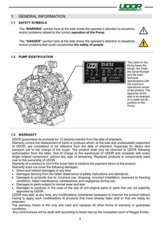
1.2 PUMP IDENTIFICATION
The Label on the Pump bears the Model, the Code, the Serial Number and the main technical specifications with the maximum operational values of the product. The specimen at the side is an example of a Label and its position on the Pump.
1.3 WARRANTY
UDOR guarantees its products for 12 (twelve) months from the date of shipment. Warranty covers the replacement of parts or products which, to the sole and undisputable judgement of UDOR, are considered to be defective from the date of shipment. Expenses for labour and transport are to the charge of the buyer. The product shall only be returned to UDOR following authorisation from the latter, free of charge to the warehouse of UDOR and complete with every single original component, without any sign of tampering. Replaced products or components pass over to the ownership of UDOR. Warranty of a product is void if the buyer fails to observe the payment terms of the product. Warranty does not cover the following damages: Direct and indirect damages of any kind. Damages deriving from the failed observance of safety instructions and standards. Damages to products due to: incorrect use, dropping, incorrect installation, exposure to freezing
conditions, failed maintenance, carelessness and negligence during use. Damages to parts subject to normal wear and tear. Damages to products in the case of the use of non-original parts or parts that are not explicitly
approved by UDOR.UDOR may add, at any time, any modifications considered necessary to improve the product without having to apply such modifications to products that have already been sold or that are ready for shipment. The warranty herein is the only one valid and replaces all other forms of warranty or guarantee conditions. Any controversies will be dealt with according to Italian law by the competent court of Reggio Emilia.
6
2. INTRODUCTIONThe Diaphragm Pumps of UDOR, with radial piston kinematic drive, are designed and manufactured to pumps or transfer water or pesticides and herbicides in water solution to be used according to the instructions of the actual producers. They are generally driven by: electric motors, endothermic petrol or diesel engines and hydraulic motors, tractor P.T.O.. Couplings may be fulfilled by means of transmission shaft, direct flanging, reduction unit or multiplier, joints, pulleys and belts.
The Pump is supplied to be installed on a more complex machine or plant; the manufacturer of such machine or plant shall add all the information related to safety of the assembled machine/plant fulfilled.
3. INTENDED USEThe Diaphragm Pumps of UDOR are designed for use in machines or systems that transfer water or pesticides or herbicides, under pressure, such as the following for example: Sprayers, Mist Sprayers, Herbicide Spray Booms, Gardening, Civil and Industrial Washing Systems, Drain and Pipe Cleaning, Fire-fighting, Antifreeze Systems. The temperature of the workplace shall be between: Min. 0°C (32°F) - Max.45°C (113°F) The Pump cannot be used submerged under any type of liquid.
4. OPERATIONAL RESTRICTIONThe specifications of the liquid to be used are described in detail herewith: do not use fordifferent liquids; in particular, it is NOT possible to use UDOR Pumps in the following conditions: - In the presence of water with high salt content, such as seawater for example.- In workplaces where there is a corrosive or explosive atmosphere.- In the presence of any liquid that is not compatible with the constructional material of thePump.- To pump paint, solvents, fuel and any flammable liquid (not suitable for ATEX workplaces).- To foodstuffs.- To wash people, animals, live electrical or electronic equipment.- To wash the Pump itself.
5. GENERAL WARNINGS- Never start the Pump under pressure.- Constantly check the state of wear of the pipes and relevant fittings, especially those underpressure. Pipes with signs of abrasion or that do not guarantee a perfect seal shall bereplaced.
- Protect rotating parts with a cover to prevent contact.- The Pump is designed to be integrated in a machine or system, with various supply systems,which may make the noise level vary, even quite substantially. The manufacturer of suchmachine or system shall assess the level of noise emitted by the assembled machine orsystem and inform the user appropriately, also in relation to the use of suitable personalprotection equipment.
6. BEFORE START UP6.1 LIQUIDS TO BE PUMPED The Pump is designed and manufactured to tranfer water or pesticides and herbicides in water solution to be used according to the instructions of the actual producers. The liquid intaken must be free from sand or other solid particles in suspension. The liquid intaken shall have viscosity and density similar to water. The temperature of the liquid to be pumped must be between 5°C (41°F) and 38°C (100°F). Any other use is not admitted unless authorised in writing by the Engineering Department of UDOR.

7
6.2 INLET AND OUTLET OF THE PUMP
The Inlet of the liquid to be pumped, also called intake or supply, is generally of larger diameter than the Outlet, also called delivery.
The Inlet and Outlet CANNOT be inverted.
6.3 INLET CONDITIONS (SUCTION)
Make sure the supply line is connected correctly and that it complies with the following requisites: - Any point of the inlet pipeline cannot be smaller than the diameter of the Pump inlet.- Be absolutely leak-proof to avoid any air infiltration.- Not have 90° bends near the Pump inlet.- Not have contractions or restrictions.- Avoid any turbolence near the Pump inlet and in the supply tank.- If an inlet filter is used, it must allow 200% more flow than the flow required by the Pump. It mustnot cause any contraction or any pressure drop. The filter should be grant a filtration degree between32 and 50 Mesh and should be cleaned on a regular basis to ensure its proper functionality.- Maximum inlet pressure admitted: 0.5 bar (7 PSI).- Maximum negative inlet pressure admitted:-0.2 bar (-3 PSI) [-6 inch.Hg].- Maximum offset admitted between pump and supply source underneath: 2 m. (6.5 ft.).
6.4 OUTLET CONDITIONS
Make sure the delivery line and all the accessories are connected correctly, secured firmly, hermetically sealed and that the pipes are sized appropriately. All pressurised pipes must be marked durably with the maximum admitted pressure, which must never be less than the maximum working pressure of the Pump, written on the Label.
6.5 SPEED AND ROTATION DIRECTION
The rotation speed of the shaft of the Pump must never exceed the RPM written on the Label of the actual Pump.
The minimum RPM admitted is: maximum RPM x 0.6. The rotation direction of the shaft of UDOR Pumps may be clockwise or anticlockwise.
7. CONTROLS ON SYSTEM
7.1 UNLOADER VALVE
A pressure regulator valve must be installed to avoid the pressure exceeding the maximum limit indicated on the Label of the Pump.
Use of the Pump, even for a short period, with a pressure higher than such limit would damage the Pump itself.
The regulator valve shall be compatible with the maximum pressure, flow rate and temperature values written on the Label and in the “INLET CONDITIONS”.
Incorrect installation of the pressure regulator valve could cause serious personal injuries and damage to property as well as seriously damaging the actual Pump. The circuit must be equipped with another safety valve to prevent the maximum pressure from being exceeded in the case of anomalies in the pressure regulator valve.
7.2 NOZZLE
A deteriorated nozzle could cause a drop in pressure; in this case, do not adjust the pressure regulator valve in the attempt to increase the pressure of the system because when the delivery line closes, this would cause a boost in pressure, which could damage the Pump. If the pressure drops, it is advisable to replace the nozzle and adjust the system’s pressure again. The flow rate of the Pump must be at least 10% higher than the flow rate that the utilities demand; the excess flow rate must be discharged.

8
7.3 PULSATION DAMPENER (ACCUMULATOR)
Before starting the Pump, verify the air pressure in the accumulator, if present. This operation may be carried out, with the Pump off, connecting an air source to the inflation valve. The air pressure should be checked periodically.
Using the Pump without air in the accumulator may cause system malfunctioning, damage the accumulator diaphragm or the whole Pump.
The accumulator’s air pressure varies according to the Pump’s operating pressure:
Pump Working Pressure bar
PSI 2
29 5
72 10
145 20
290 30
435 40
580 50
725
Accumulator Pressure bar
PSI 1
15 2
29 4
58 5
72 6
87 7
102 8
116
UDOR normally inflates the Pumps pulsation dampener at a pressure of 5 bar (72 PSI) approx.
7.4 PRESSURE GAUGE
Install a gauge as near as possible to the outlet of the Pump because the maximum pressure written on the Pump’s Label refers to the pressure detected in that point and not on the nozzle or on other accessories.
All the components of the machine or of the circuit must have technical specifications compatible with the data written on the Pump’s Label.
8. INSTALLATION, START UP AND SWITCHING OFF8.1 POSITIONING
Smaller and lighter pumps can be handled by hand in compliance with current standards. Heavier pumps must be handled using a suitable lifting device. If you need to use a lifting device, use appropriate strap/s, being careful not to damage the product. The weight of the pumps is written in the table on page 17. To safeguard the lifetime of the components subject to wear and tear such as valves and diaphragms, the pump should be installed below or at water level. UDOR Diaphragm Pumps are, in any case, self-priming; they may be installed above the water source. In this case, the maximum allowed difference in height is 2 mt. (6.5 ft.). If the Pump is used in a particularly dirty workplaces or is exposed to atmospheric agents, you are recommended to protect it, respecting the ventilation conditions.
8.2 ASSEMBLY
Fit the Pump on a rigid surface keeping the power take-off and support feet horizontal to ensure correct drainage in the case of leakage of water or oil. The Pump must be secured firmly on a base, which must be perfectly aligned with the transmission components. In the case of belt transmission, make sure the pulleys are aligned and check the tension of the belts. Use appropriately sized hoses, both on the inlet and outlet of the Pump, according to the technical specifications written on the Label.
8.3 START UP
Before starting, check the following: - Check the oil level through the dedicated oil reservoir or inspection cap; top-up if necessary.- Check the pressure value on the accumulator, if installed; inflate or deflate if necessary.- The pressure regulator valve must be set at “0” pressure to favour intake.Start and run the Pump for approximately 10 seconds until all the liquid has discharged from thedelivery line. Once the intake cycle is complete, you can set the Pump at the required pressure, byadjusting the pressure regulator valve, without ever exceeding the maximum pressure written on thePump’s Label.
8.4 SWITCHING OFF AND STORAGE
After use or if the Pump is to be put away in storage, wash it internally. You can do this by running the Pump for several minutes with clean water, then disconnect the supply line and leave the Pump to run for approximately 15 seconds so that all the water inside the pump is drained. A few minutes devoted to the internal washing of the pump brings considerable benefits in terms of the pump’s lifetime.
Never leave liquid inside the pump. Damage to the diaphragms or to other components is often caused by liquid that is left inside the pump for a long time.
Do not wash the Pump externally: water could get into the Pump crankcase, for example through the seal rings of the crankshaft.
Do not throw the liquid used to wash the Pump outdoors but observe current standards.
8.5 PRECAUTIONS AGAINST FREEZING
If shutdown during winter or in the case of places and seasons subject to frost, once the Pump has finished working, run it for the time required to Pump an emulsion of 50% of clean water and 50% of antifreeze fluid through it in order to prevent freezing and damage to the Pump.
The Pump must not be used to Pump antifreeze fluid that is not mixed with water. In the presence of ice or very cold temperatures at the workplace, the Pump must neverbe started, otherwise the Pump could be seriously damaged. To start the system, the wholecircuit must be completely defrosted.
9. MAINTENANCE9.1 ROUTINE MAINTENANCE
If the Pump is used for light-duty purposes, the following routine maintenance jobs are advised:
- After the first 50 hours: Oil change (see section 9.2 - Lubrication)
- Every 500 hours: Oil change - Replace the diaphragms (see instructions below)
- Every 1000 hours: Replace the valves
For heavy-duty purposes, carry out the maintenance jobs more often.
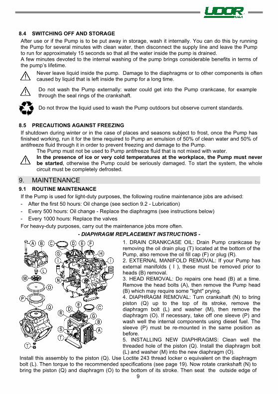
- DIAPHRAGM REPLACEMENT INSTRUCTIONS -
1. DRAIN CRANKCASE OIL: Drain Pump crankcase byremoving the oil drain plug (T) located at the bottom of thePump, also remove the oil fill cap (F) or plug (R).2. EXTERNAL MANIFOLD REMOVAL: If your Pump hasexternal manifolds ( I ), these must be removed prior toheads (B) removal.3. HEAD REMOVAL: Do repairs one head (B) at a time.Remove the head bolts (A), then remove the Pump head(B) which may require some "light" prying.4. DIAPHRAGM REMOVAL: Turn crankshaft (N) to bringpiston (Q) up to the top of its stroke, remove thediaphragm bolt (L) and washer (M), then remove thediaphragm (O). If necessary, take off one sleeve (P) andwash well the internal components using diesel fuel. Thesleeve (P) must be re-mounted in the same position asbefore.5. INSTALLING NEW DIAPHRAGMS: Clean well thethreaded hole of the piston (Q). Install the diaphragm bolt(L) and washer (M) into the new diaphragm (O).
Install this assembly to the piston (Q). Use Loctite 243 thread locker o equivalent on the diaphragm bolt (L). Then torque to the recommended specifications (see page 19). Now rotate crankshaft (N) to bring the piston (Q) and diaphragm (O) to the bottom of its stroke. Then seat the outside edge of
9

10
the diaphragm (O) into the Pump body. 5. INSTALLING NEW DIAPHRAGMS: Clean well the threaded hole of the piston (Q). Install thediaphragm bolt (L) and washer (M) into the new diaphragm (O). Install this assembly to the piston(Q). Use Loctite 243 thread locker o equivalent on the diaphragm bolt (L). Then torque to therecommended specifications (see page 19). Now rotate crankshaft (N) to bring the piston (Q) anddiaphragm (O) to the bottom of its stroke. Then seat the outside edge of the diaphragm (O) into thePump body.6. HEAD INSTALL: When reinstalling the Pump head (B) it is very important to make sure that thecheck valves are installed correctly. For each cylinder there are two valves, one valve lets the fluidflow into to the head, the other valve lets the fluid flow out of the head. PAY VERY CLOSEATTENTION TO THIS. After having correctly positioned the Pump head (B), tighten the screws (A)with the proper torque (see page 19).7. INSTALLING PULSATION DAMPENER DIAPHRAGM: Bleed off the air in the chamber using theair-valve (G) on the dampener, then remove the cover bolts (E), cover (D) and diaphragm (C), installcorrectly the new diaphragm (C). Reinstall cover (D) and tighten the screws (A) with the propertorque (see page 19). Recharge dampener with air according to UDOR specifications at page 13.8. REFILL PUMP CRANKCASE: Re-mount the oil drain plug (T). Fill Pump with SAE 15W-40 OIL torecommended mark on the oil reservoir (H) or on the sight glass (S). Rotate the crankshaft (N) whilefilling to eliminate air pockets. Re-mount the oil fill cap (F) or the oil fill plug (R).9. INITIAL START UP: Start the Pump with the outlet line at “0” pressure; after about 5 minutes at “0”pressure you may increase the outlet pressure and make a few cycles of pressure on/off. This willevacuate any remaining air pockets in the crankcase. Turn Pump off and re-check oil level. Refill asnecessary to proper oil level.IMPORTANT: During initial start up, monitor the oil color. If it turns milky white, the diaphragms werenot seated correctly.
9.2 LUBRICATION
The Pump is supplied with the correct amount of lubrication oil (see table on page 17). Periodically check the oil level in the Pump through the oil level indicator. Use OIL type SAE 15W-40 or equivalent. Here are some recommended types of oil:
BRAND TYPE
AGIP F.1 Supermotoroil 15W-40
BP Vanellus C 15W-40
CASTROL GTX 15W-40
ESSO Uniflo 15W-40
MOBIL Super M 15W-40
SHELL Rimula R4 15W-40 / Helix Super 15W40
TOTAL Rubia 15W-40 / Quartz 5000 15W-40
The oil is to be changed by draining it through the dedicated bottom discharge cap and strictly with the Pump stopped.
The oil level could vary during priming ; then it will stabilize when the system is pressurized. If the oil level gets lower during the first few hours of the pump’s operation , it could be normal. Simply refill . If instead , the oil level changes considerably after several hours of operation, the pump’s diaphragms might be damaged or there might be restrictions along the suction line.
DO NOT START THE PUMP IF THERE IS NO OIL IN THE PUMP!
During maintenance, you are recommended to: - Use and wear suitable personal protection equipment (i.e. gloves).- Wait for the machine to cool down and to have stopped completely.

11
During maintenance, do not throw residues outdoors but observe current standards.
If the Pump is to be scrapped: 1. Separate the various parts depending on their type (i.e. plastic, harmful fluids, metaletc.).2. Use public or private waste disposal systems envisaged by local law to dispose ofwaste.3. This device could contain harmful substances: improper use or incorrect disposalcould have negative effects on human health and on the environment.
10.
10. TROUBLE SHOOTING
PROBLEMS PROBABLE CAUSES SOLUTIONS
No pressure.
Very little pressure.
Pressure drops below working range when relief valve is open to boom or gun.
Insufficient strainer capacity, or dirty or plugged strainer.
Use larger capacity strainer or clean strainer.
Suction hose restriction. Eliminate restriction. Collapsed suction hose inside or outside tank restricting flow.
Replace collapsed hose.
Air leak in inlet line. Examine hoses and fittings, ensure air tight fit and no leaks.
Pressure relief valve stuck or worn. Repair or replace relief valve (§). Excessive tank foam due to low tank volume.
Refill tank.
Nozzle volume is greater than Pump capacity.
a. Check relief valve adjustment.b. Reduce nozzle orifice size ornumber of nozzles used.
One or more check valves seating improperly.
Clean or replace check valves(§).
Excessive gauge vibration.
Excessive pulsation.
Pulsation dampener pressure too low or too high.
Adjust pulsation dampener pressure. (see page 21) – (§).
Air leak in inlet line. Examine hoses and fittings, ensure air tight fit and no leaks.
Insufficient strainer capacity, or dirty or plugged strainer.
Use larger capacity strainer or clean strainer.
Air not entirely evacuated from Pump cavity.
Run Pump with an open discharge to totally evacuate air.
Pump does not suck water.
Air leak in inlet line. Examine hoses and fittings, ensure air tight fit and no leaks.
Insufficient strainer capacity, or dirty or plugged strainer.
Use larger capacity strainer or clean strainer.
One or more check valves seating improperly.
Clean or replace check valves(§).
Pump oil has milky color.
The Pump oil comes out of discharge line; the oil level drops markedly.
Oil plug pops out.
One or more diaphragms failures.
STOP THE PUMP IMMEDIATELY!
Replace the diaphragms (§). Diaphragms replacement instructions: see pages 22-23.
(§)These operations must be carried out by qualified personnel.

12
11. OIL AND WEIGHT
SERIES RECOMMENDED OIL QUANTITY PUMP WEIGHT
Kg. Lbs. Lt. Gal. Kg. Lbs.
ZETA 70 0,50 1.10 0,56 0.15 9 20
ZETA-P 40 ZETA-P 85
ZETA-P 100 1,02 2.25 1,14 0.30 12 26
ZETA 85 1,02 2.25 1,14 0.30 12 26
ZETA 100 1,02 2.25 1,14 0.30 13 29
ZETA 120 ZETA 140 1,04 2.29 1,16 0.31 18 40
ZETA 170 1,15 2.54 1,28 0.34 24 53
ZETA 200 1,15 2.54 1,28 0.34 26 57
ZETA 230 ZETA 260
2,40 5.29 2,68 0.71 36 79
ZETA 300 2,50 5.51 2,79 0.74 38 84
ZETA 350 ZETA 400 4,10 9.04 4,58 1.21 63 139
IOTA 20 IOTA 25 0,18 0.40 0,20 0.05 4 9
KAPPA 15 0,10 0.22 0,11 0.03 2,5 5.5
KAPPA 25 KAPPA 32 0,26 0.57 0,29 0.08 8 18
KAPPA 40 KAPPA 50 0,49 1.08 0,55 0.15 11 24
KAPPA 33 KAPPA 43 KAPPA 53
0,56 1.23 0,63 0.17 11 24
KAPPA 55 KAPPA 65 0,62 1.37 0,69 0.18 13 29
DELTA 75 1,04 2.29 1,16 0.31 19 42
DELTA 100 1,02 2.25 1,14 0.30 22 49
DELTA 125 1,82 4.01 2,03 0.54 30 66
DELTA 140 1.45 3.20 1.62 0.42 28 62
DELTA 170 1.80 3.96 2.00 0.52 43 94
OMEGA 135 1.45 3.20 1.62 0.42 28 62
OMEGA 139 1.45 3.20 1.62 0.42 28 62
OMEGA 170 2,42 5.33 2,70 0.71 45 99
BETA-S 135 1.45 3.20 1.62 0.42 28 62
BETA 110 2,14 4.72 2,39 0.63 45 99
BETA 170 2,42 5.33 2,70 0.71 52 115
BETA 200 BETA 240 4,50 9.92 5,03 1.33 75 165

13
12. TORQUE SPECIFICATIONS

14
TORQUE SPECIFICATIONS
1 2 3 4 5 6 7 8 9
Dia
phra
gm B
olt
(u
se L
oct
ite®
243)
Hea
d B
olt
s
Puls
atio
n
Dam
pen
er B
olt
s
Inle
t F
lange
Bolt
s
Bea
rin
g F
lange
B
olt
s
Oil
Cup B
olt
s
Man
ifold
Bolt
s (A
lum
iniu
m /
Bra
ss)
Man
ifold
Bolt
s (P
last
ic)
Val
ves
Cover
Bolt
MOD. N•m lbf•ft N•m lbf•ft N•m lbf•ft N•m lbf•ft N•m lbf•ft N•m lbf•ft N•m lbf•ft N•m lbf•ft N•m lbf•ft
ZETA 70 25 18 25 18 - - - - - - - - - - - - - - - - - - 8 6 - - - - - - 10 7 - - - - - - ZETA-P 40 ZETA-P 85
ZETA-P 100 \ 18 40 30 - - - - - - - - - - - - - - - - - - 8 6 - - - - - - 20 14 - - - - - -
ZETA 85 25 18 40 30 - - - - - - - - - - - - - - - - - - 8 6 - - - - - - 20 14 - - - - - -
ZETA 100 25 18 40 30 25 18 - - - - - - - - - - - - 8 6 - - - - - - 20 14 - - - - - - ZETA 120 ZETA 140 30 22 40 30 25 18 - - - - - - - - - - - - 8 6 - - - - - - 20 14 - - - - - -
ZETA 170 ZETA 200 30 22 40 30 25 18 - - - - - - 34 25 8 6 - - - - - - 20 14 - - - - - -
ZETA 230 ZETA 260 ZETA 300
30 22 40 30 - - - - - - - - - - - - 34 25 8 6 - - - - - - 20 14 - - - - - -
ZETA 350 ZETA 400 30 22 85 63 - - - - - - - - - - - - 34 25 10 7 30 22 20 14 - - - - - -
IOTA 20 IOTA 25 14 10 25 18 25 18 - - - - - - 25 18 - - - - - - - - - - - - - - - - - - - - - - - -
KAPPA 15 14 10 14 10 14 10 - - - - - - 10 7 - - - - - - - - - - - - - - - - - - - - - - - - KAPPA 25 KAPPA 32 25 18 40 30 40 30 - - - - - - - - - - - - - - - - - - - - - - - - - - - - - - - - - - - -
DELTA 40 DELTA 50 25 18 40 30 40 30 - - - - - - 34 25 - - - - - - - - - - - - - - - - - - - - - - - -
KAPPA 33 KAPPA 43 KAPPA 53
25 18 40 30 - - - - - - 10 7 - - - - - - 8 6 - - - - - - - - - - - - - - - - - -
KAPPA 55 KAPPA 65 25 18 40 30 40 30 10 7 34 25 8 6 - - - - - - - - - - - - - - - - - -
DELTA 75 25 18 40 30 40 30 10 7 34 25 8 6 - - - - - - - - - - - - 25 18
DELTA 100 25 18 40 30 28 20 10 7 34 25 8 6 - - - - - - - - - - - - 25 18
DELTA 125 25 18 40 30 28 20 10 7 34 25 8 6 - - - - - - - - - - - - 25 18 DELTA 140 30 22 90 67 25 18 50 36 50 36 10 7 11 8 - - - - - - 50 36
DELTA 170 30 22 90 67 25 18 50 36 50 36 10 7 11 8 - - - - - - 50 36
OMEGA 135 30 22 85 63 - - - - - - - - - - - - 34 25 10 7 30 22 - - - - - - - - - - - - OMEGA 139 30 22 85 63 - - - - - - - - - - - - 34 25 10 7 30 22 - - - - - - - - - - - -
OMEGA 170 30 22 50 37 28 20 - - - - - - 34 25 10 7 30 22 - - - - - - - - - - - -
BETA-S 135 30 22 85 63 - - - - - - - - - - - - 34 25 10 7 30 22 - - - - - - - - - - - - BETA 110 30 22 50 37 28 20 - - - - - - 34 25 10 7 30 22 - - - - - - - - - - - -
BETA 170 30 22 50 37 28 20 - - - - - - 34 25 10 7 30 22 - - - - - - - - - - - - BETA 200 BETA 240 30 22 50 37 - - - - - - - - - - - - 34 25 10 7 30 22 - - - - - - - - - - - -
15
DECLARATION OF INCORPORATION OF PARTLY COMPLETED MACHINERY according to Machinery Directive (2006/42/CE and subsequent amendments) and the implementing provisions.
The manufacturer: UDOR S.p.A.
Via A. Corradini, 2 - 42048 Rubiera (Reggio Emilia) - Italia in the person of its legal representative
declares under its sole responsibility that the “partly completed machinery” of its own production, namely: Diaphragm Pumps, series
ZETA - ZETA-P - RO - IOTA - KAPPA - DELTA - OMEGA - BETA which this declaration is referred to, is in conformity with the essential safety requirements of Directive 2006/42/EC, for which it is
applied and respected in all the essential issues:
• from 1.1.1 to 1.1.3 • from 1.2.6 to 1.3.2 • 1.3.8.2 • 1.5.13 • 1.7.2• from 1.1.5 to 1.1.5 • 1.3.4 • from 1.4.1 to 1.4.2.1 • from 1.6.1 to 1.6.2 • from 1.7.4 to 1.7.4.3• 1.2.4.3 • from 1.3.7 to 1.3.8 • from 1.5.2 to 1.5.8 • from 1.6.4 to 1.7.1
with the Relevant Technical Documentation conforming to the annex VII B.They also comply with the following Standard: UNI EN 809.
It is additionally specified that: • The Relevant Technical Documentation is kept at UDOR S.p.A. premises in: Via A. Corradini, 2 – 42048 Rubiera (Reggio Emilia)– Italy, in the person of its legal representative. • Any reasoned request by national authorities will be fulfilled with the relevant information on the “Partly Completed Machinery”.• The “Partly Completed Machinery” Diaphragm Pumps cannot be operated until the machine where they are incorporated into, has complied with the same Directive 2006/42/EC and with the other potentially applicable Directives.
Rubiera, 29/12/2009 Marco Zanasi (CEO UDOR S.p.A.)
is forbidden to reproduce or translate any part of this manual without written authorisation from the owner. UDOR S.p.A. reserves the right to add modifications to the products, information and illustrations herein without notice..
UDOR S.p.A. Via A. Corradini, 2 - 42048 Rubiera (Reggio Emilia) - ITALY
Tel. (+39) 0522 628249 - Fax (+39) 0522 628953 [email protected] - www.udor.it
080594
06/20
Rev. 3.1