USE AND CARE MANUAL - Sure HeatUSE AND CARE MANUAL FOR OUTDOOR USE ONLY ALWAYS KEEP YOUR GRILL...
28
USE AND CARE MANUAL FOR OUTDOOR USE ONLY ALWAYS KEEP YOUR GRILL COVERED WHEN NOT IN USE BEFORE YOU BEGIN – We’ve included easy-to-follow, step-by-step instructions which have been carefully written to ensure quick assembly of your grill. Reading the instructions will be a time saver in the end. YOU WILL NEED – A Phillips screwdriver, adjustable wrench, 1/2 wrench or socket and a 1/4” nut driver or socket will be needed to assemble this grill. All other necessary hardware has been included. QUESTIONS? – We’re here to help. Just call 1-800-320-0859. For faster service, have the model number and serial number handy when calling. Amana TM SS 4 Burner Gas Grill
Transcript of USE AND CARE MANUAL - Sure HeatUSE AND CARE MANUAL FOR OUTDOOR USE ONLY ALWAYS KEEP YOUR GRILL...

USE AND CARE MANUALFOR OUTDOOR USE ONLY
ALWAYS KEEP YOUR GRILL COVERED WHEN NOT IN USE
BEFORE YOU BEGIN – We’ve included easy-to-follow, step-by-step instructions which have been carefully written toensure quick assembly of your grill. Reading the instructions will be a time saver in the end.
YOU WILL NEED – A Phillips screwdriver, adjustable wrench, 1/2 wrench or socket and a 1/4” nut driver or socket will beneeded to assemble this grill. All other necessary hardware has been included.
QUESTIONS? – We’re here to help. Just call 1-800-320-0859. For faster service, have the model number and serial number handy when calling.
AmanaTM SS 4 Burner Gas Grill

Welcome & Congratulations
1
Please retain this manual for future reference
AmanaTM is a registered trademark of the Maytag Corporation and is used under licenseto Sure Heat Manufacturing
© 2006 Sure Heat Manufacturing All rights reserved
Congratulations on your purchase of a new grill! We atSure Heat Mfg. are very proud of our product and weare completely committed to providing you with the bestservice possible. Your satisfaction is our #1 priority.
Please read this Use & Care Manual very carefully. Itcontains valuable information on how to properlymaintain your new grill.
We know you’ll enjoy your new grill and thank you forchoosing our product. We hope you consider us forfuture purchases.
PLEASE READ AND SAVE THESE INSTRUCTIONS
This Use & Care Manual provides specific operatinginstructions for your model. Use your grill only asinstructed in this manual. These instructions are notmeant to cover every possible condition and situationthat may occur. Common sense and caution must bepracticed when installing, operating and maintaining anyappliance.
Please record your model and serial numbers below forfuture reference.This information is found on the serialplate located on the back of the built-in grill .
NOTE: Use only soap and water to clean serial plate.
Model Number: ______________________________
Serial Number: ______________________________
Purchase Date: ______________________________
Gas Type: __________________________________
Please complete and mail in the ProductRegistration Card included with your grill.
Questions?1-800-320-0859
Register Your ProductThe PRODUCT REGISTRATION CARDshould be filled in completely, signedand returned to Electrolux HomeProducts North America.
Please attach sales receipt here forfuture reference.
Register Your ProductThe PRODUCT REGISTRATION CARDshould be filled in completely signed and returned to Sure Heat Manufacturing.
General Safety Instructions
2
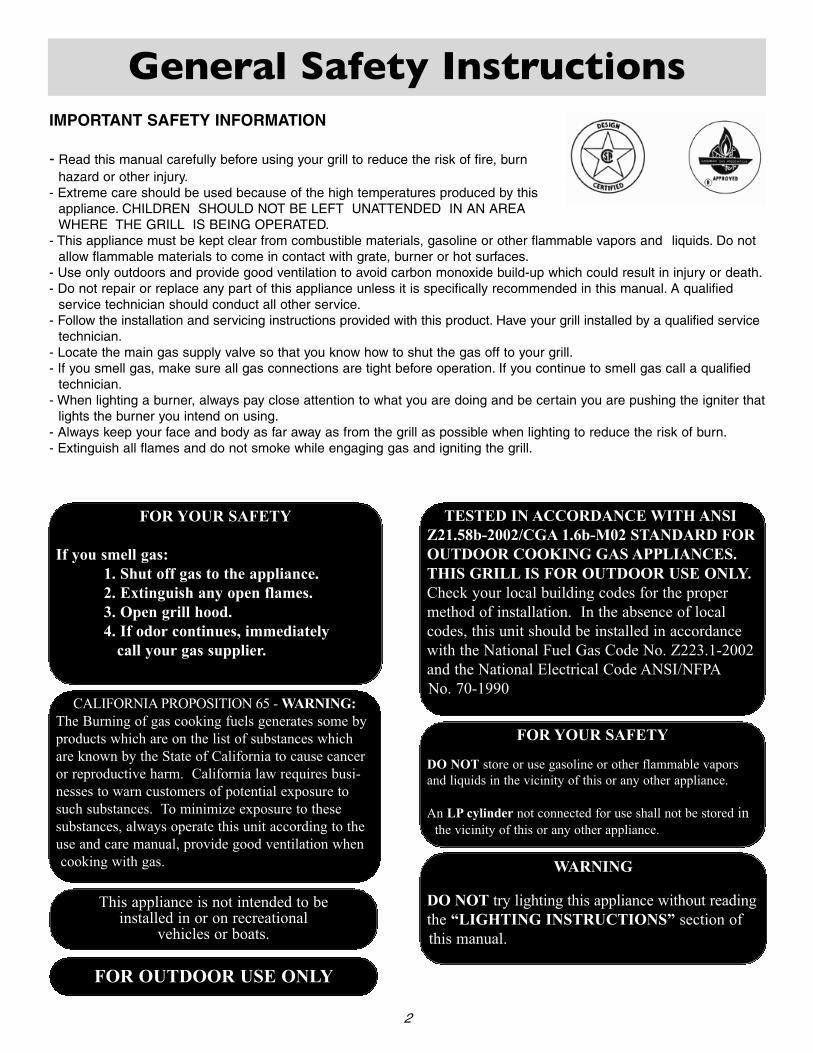
TESTED IN ACCORDANCE WITH ANSIZ21.58b-2002/CGA 1.6b-M02 STANDARD FOROUTDOOR COOKING GAS APPLIANCES.THIS GRILL IS FOR OUTDOOR USE ONLY.Check your local building codes for the propermethod of installation. In the absence of localcodes, this unit should be installed in accordancewith the National Fuel Gas Code No. Z223.1-2002and the National Electrical Code ANSI/NFPANo. 70-1990
WARNING
DO NOT try lighting this appliance without readingthe “LIGHTING INSTRUCTIONS” section ofthis manual.
FOR YOUR SAFETY
DO NOT store or use gasoline or other flammable vaporsand liquids in the vicinity of this or any other appliance.
An LP cylinder not connected for use shall not be stored inthe vicinity of this or any other appliance.
IMPORTANT SAFETY INFORMATION
- Read this manual carefully before using your grill to reduce the risk of fire, burn hazard or other injury.
- Extreme care should be used because of the high temperatures produced by thisappliance. CHILDREN SHOULD NOT BE LEFT UNATTENDED IN AN AREAWHERE THE GRILL IS BEING OPERATED.
- This appliance must be kept clear from combustible materials, gasoline or other flammable vapors and liquids. Do notallow flammable materials to come in contact with grate, burner or hot surfaces.
- Use only outdoors and provide good ventilation to avoid carbon monoxide build-up which could result in injury or death.- Do not repair or replace any part of this appliance unless it is specifically recommended in this manual. A qualified
service technician should conduct all other service.- Follow the installation and servicing instructions provided with this product. Have your grill installed by a qualified service
technician.- Locate the main gas supply valve so that you know how to shut the gas off to your grill.- If you smell gas, make sure all gas connections are tight before operation. If you continue to smell gas call a qualified
technician.- When lighting a burner, always pay close attention to what you are doing and be certain you are pushing the igniter that
lights the burner you intend on using.- Always keep your face and body as far away as from the grill as possible when lighting to reduce the risk of burn.- Extinguish all flames and do not smoke while engaging gas and igniting the grill.
FOR YOUR SAFETY
If you smell gas:1. Shut off gas to the appliance.2. Extinguish any open flames.3. Open grill hood.4. If odor continues, immediately
call your gas supplier.
FOR OUTDOOR USE ONLY
This appliance is not intended to beinstalled in or on recreational
vehicles or boats.
CALIFORNIA PROPOSITION 65 - WARNING:The Burning of gas cooking fuels generates some byproducts which are on the list of substances whichare known by the State of California to cause canceror reproductive harm. California law requires busi-nesses to warn customers of potential exposure tosuch substances. To minimize exposure to these substances, always operate this unit according to theuse and care manual, provide good ventilation whencooking with gas.
Grill Features
3
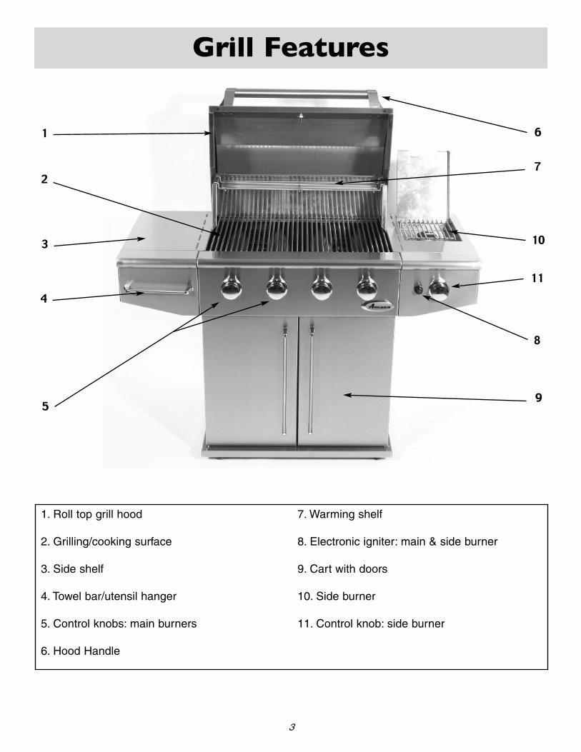
1. Roll top grill hood
2. Grilling/cooking surface
3. Side shelf
4. Towel bar/utensil hanger
5. Control knobs: main burners
6. Hood Handle
7. Warming shelf
8. Electronic igniter: main & side burner
9. Cart with doors
10. Side burner
11. Control knob: side burner
2
1 6
7
9
10
11
8
5
3
4
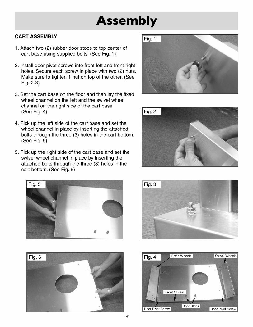
CART ASSEMBLY
1. Attach two (2) rubber door stops to top center ofcart base using supplied bolts. (See Fig. 1)
2. Install door pivot screws into front left and front rightholes. Secure each screw in place with two (2) nuts.Make sure to tighten 1 nut on top of the other. (SeeFig. 2-3)
3. Set the cart base on the floor and then lay the fixedwheel channel on the left and the swivel wheelchannel on the right side of the cart base.(See Fig. 4)
4. Pick up the left side of the cart base and set thewheel channel in place by inserting the attachedbolts through the three (3) holes in the cart bottom.(See Fig. 5)
5. Pick up the right side of the cart base and set theswivel wheel channel in place by inserting theattached bolts through the three (3) holes in thecart bottom. (See Fig. 6)
Fig. 6
Fig. 1
Fig. 3
Fig. 2
Fig. 4
Fig. 5
Assembly
4
Swivel WheelsFixed Wheels
Front Of Grill
Door Pivot Screw Door Pivot ScrewDoor Stops

6. Place the left cart side onto the two (2) outer fixedwheel channel bolts, make sure the large flange istoward the front of the cart base. (See Fig. 7)
7. Secure the left cart side in place by hand tighteningnuts onto the wheel channel bolts. (See Fig. 8)
8. Place the right cart side onto the two (2) outerswivel wheel channel bolts, make sure the largeflange is toward the front of the cart base.(See Fig. 9)
9. Secure the right cart side in place by hand tighteningnuts onto the wheel channel bolts. (See Fig. 8)
Fig. 7
Fig. 8
Fig. 9
Assembly
5
Large Flange Toward Front
Large Flange Toward Front

10. Place the cart back onto the two (2) rear wheelchannel bolts. (See Fig. 10)
11. It twill be necessary to push the top of the leftand right sides outward slightly to get the cartback down completely on the base. (See Fig. 11)
12. Press the sides back together making sure thatthe side flanges cover the cart back flange.(See Fig. 12)
13. Attach three (3) self tapping screws through theleft cart side into the cart back. Repeat for rightcart side. (See Fig. 13)
14. Fasten two (2) nuts onto the back wheel channelbolts. (See Fig. 14)
15. Tighten all six (6) wheel channel nuts with awrench. (See Fig. 15)
Fig. 14
Fig. 15
Fig. 10
Fig. 11
Fig. 12
Fig. 13
Assembly
6
Large Flange WithHoles On Bottom

MOUNTING GRILL TO CART
1. Loosen the four (4) grill mounting bolts so that thereis approximately 1/4” between the bolt head and grillbottom. (See Fig. 16)
2. Have someone help you pick up the grill and set itsquarely on top of the cart. (See Fig. 17)
3. Make sure the four (4) bolts fall through the largeopening on the key hole slots on the sides of thecart. (See Fig. 18)
4. Slide the grill forward in the key hole slots until thefront grill flange rests against the side cart flanges.(See Fig. 19)
5. Install two (2) self tapping screws into the top leftand right cart flanges. (See Fig. 19)
6. Tighten the four (4) grill head mounting bolts under-neath the grill to secure the grill to the cart.(See Fig. 20)
Fig. 16
Assembly
7
Mounting Bolts
Fig. 17
Fig. 19Fig. 20
Fig. 18
Side Cart Flange
Key Hole Slot
Bolt Head Inserted Here
Front Grill Flange

Fig. 22
Fig. 23
Fig. 24
7. Using the four (4) long self tapping screws, installthe door catch magnets to the bottom of the frontgrill flange. Start one screw and then the otherbefore tightening. Make sure to install the screws at a slight angle as shown. (See Fig. 21)
8. Place left hand door on an angle over the left sidedoor pivot. (See Fig. 22)
9. Tilt the top of the door toward the grill, whiledepressing the top door pivot pin above the dooredge. (See Fig. 23)
10. Move the door slightly until the pin locks into placein the hole on top of the door. (See Fig. 24)
11. Repeat steps 8-10 for right door installation.
Fig. 21
Assembly
8
Install Screws AtAn Angle
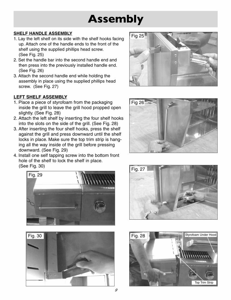
SHELF HANDLE ASSEMBLY1. Lay the left shelf on its side with the shelf hooks facing
up. Attach one of the handle ends to the front of theshelf using the supplied phillips head screw.(See Fig. 25)
2. Set the handle bar into the second handle end andthen press into the previously installed handle end.(See Fig. 26)
3. Attach the second handle end while holding theassembly in place using the supplied phillips headscrew. (See Fig. 27)
LEFT SHELF ASSEMBLY1. Place a piece of styrofoam from the packaging
inside the grill to leave the grill hood propped openslightly. (See Fig. 28)
2. Attach the left shelf by inserting the four shelf hooksinto the slots on the side of the grill. (See Fig. 28)
3. After inserting the four shelf hooks, press the shelfagainst the grill and press downward until the shelflocks in place. Make sure the top trim strip is hang-ing all the way inside of the grill before pressingdownward. (See Fig. 29)
4. Install one self tapping screw into the bottom fronthole of the shelf to lock the shelf in place.(See Fig. 30)
Assembly
9
Fig. 30
Fig. 27Fig. 29
Fig. 28
Top Trim Strip
Styrofoam Under Hood
Fig 26
Fig 25

SIDE BURNER ASSEMBLY
1. Lay the side burner on its side with the shelf hookspointing up. Slide the valve assembly through thecenter hole in the front of the shelf. Make sure theflared fitting on the valve is facing toward the bottomof the shelf. (See Fig. 31)
2. Insert one valve screw through the bezel and in tothe side burner valve and tighten. Make sure thebezel is installed correctly with the H facing theigniter hole. (See Fig. 32)
3. Insert the second valve screw through the bezel andinto the side burner valve. Tighten both screwssecurely. (See Fig. 32)
4. Press the side burner assembly into the side burnertray and install two (2) self tapping screws.(See Fig. 33-34)
Fig. 32
Fig. 33
Fig. 34
Assembly
10
Fig. 31
Flared Fitting
“H” On BezelFacing Igniter
Hole
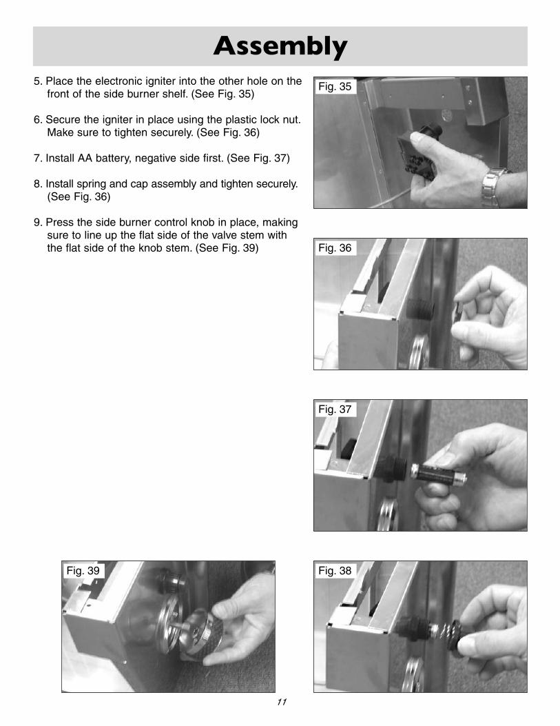
5. Place the electronic igniter into the other hole on thefront of the side burner shelf. (See Fig. 35)
6. Secure the igniter in place using the plastic lock nut.Make sure to tighten securely. (See Fig. 36)
7. Install AA battery, negative side first. (See Fig. 37)
8. Install spring and cap assembly and tighten securely.(See Fig. 36)
9. Press the side burner control knob in place, makingsure to line up the flat side of the valve stem withthe flat side of the knob stem. (See Fig. 39)
Fig. 39
Fig. 36
Fig. 37
Fig. 38
Assembly
11
Fig. 35
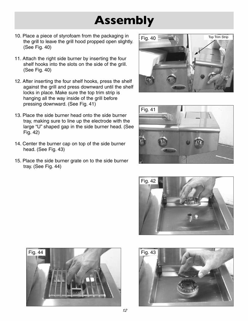
10. Place a piece of styrofoam from the packaging inthe grill to leave the grill hood propped open slightly.(See Fig. 40)
11. Attach the right side burner by inserting the fourshelf hooks into the slots on the side of the grill.(See Fig. 40)
12. After inserting the four shelf hooks, press the shelfagainst the grill and press downward until the shelflocks in place. Make sure the top trim strip ishanging all the way inside of the grill before pressing downward. (See Fig. 41)
13. Place the side burner head onto the side burnertray, making sure to line up the electrode with thelarge “U” shaped gap in the side burner head. (SeeFig. 42)
14. Center the burner cap on top of the side burnerhead. (See Fig. 43)
15. Place the side burner grate on to the side burnertray. (See Fig. 44)
Fig. 40
Fig. 41
Assembly
12
Fig. 42
Fig. 43Fig. 44
Top Trim Strip

Fig. 46
CONNECTING IGNITER WIRES
1. Attach the large connector of the loose packagedside burner wire to the terminal under the sideburner head. (See Fig. 45)
2. Connect the other end of the side burner wire toone of the outlets on the electronic igniter. NOTE: Itdoes not matter which wire goes where on the elec-tronic igniter. (See Fig. 46)
3. Plug the remaining wires coming out of the side ofthe grill into the terminals of the electronic igniter.(See Fig. 46)
Fig. 45
Assembly
13

ATTACHING THE HOSE AND REGULATORASSEMBLY
1. Feed the longer hose of the dual hose and regulatorassembly through the grommeted hole in the rightside of the cart. (See Fig. 47)
2. Attach the fitting to the side burner valve and tight-en securely with a wrench. (See Fig. 48)
3. Attach the remaining shorter hose to the main inletfitting on the bottom of the grill and tighten securelywith a wrench. (See Fig. 49)
ATTACHING CONDIMENT BASKET AND TOOLHANGERS
1. Slide the condiment basket into the slots locatedinside of the left hand cart door. (See Fig. 50)
2. Slide the “S” hook tool hangers onto the utensilhanger located on the left shelf. (See Fig. 51)
Assembly
14
Fig. 47
Fig. 48
Fig. 49
Fig. 50Fig. 51

Fig. 52
Fig. 53
Fig. 54
IGNITER SHIELD INSTALLATION
1. Remove the four (4) screws on the back side of themain grill burners. (See Fig. 52)
2. Place the igniter shield over each burner and igniterassembly and reinstall the four (4) screws.(See Fig. 54-55)
Assembly
15
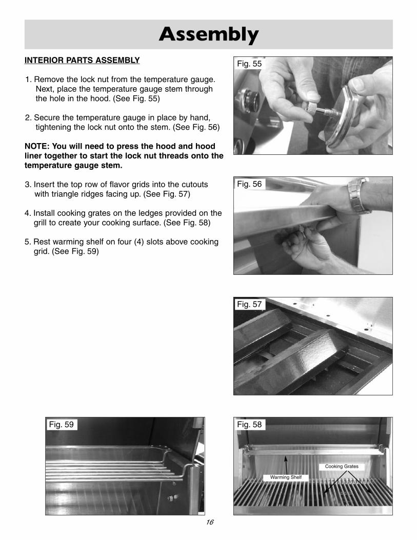
INTERIOR PARTS ASSEMBLY
1. Remove the lock nut from the temperature gauge.Next, place the temperature gauge stem throughthe hole in the hood. (See Fig. 55)
2. Secure the temperature gauge in place by hand,tightening the lock nut onto the stem. (See Fig. 56)
NOTE: You will need to press the hood and hoodliner together to start the lock nut threads onto thetemperature gauge stem.
3. Insert the top row of flavor grids into the cutoutswith triangle ridges facing up. (See Fig. 57)
4. Install cooking grates on the ledges provided on thegrill to create your cooking surface. (See Fig. 58)
5. Rest warming shelf on four (4) slots above cookinggrid. (See Fig. 59)
Fig. 55
Fig. 56
Assembly
16
Fig. 57
Fig. 58Fig. 59
Cooking Grates
Warming Shelf
Gas Requirements
17
GENERAL INFORMATION
Never attach an unregulated gas line to the appliance. Connection to an unregulated gas line cancause excessive heat or fire.
Verify the type of gas supply to be used, either Natural Gas (N.G.) or Liquid Propane (L.P.), and make sure the serial plateagrees with that of the supply. Conversion kits are available separately for an additional cost which will enable you to convertyour grill from L.P. to N.G. or to convert your grill from N.G. to L.P. Please see your local dealer for more information.
NOTE: Always have a qualified service technician perform difficult conversions or modifications.
For natural gas installations, an installer must supply a gas shutoff valve that is easily accessible to the grill. All installer sup-plied parts must conform to local codes, or in the absence of local codes, with the National Electrical Code, ANSI/NFPA 70-1990, and the National Fuel Gas Code, ANSI Z223.1-1998.
All pipe sealants must be an approved type and resistant to the actions of L.P. gases. Never use pipe sealant on flare fittings. All gas connections should be made by a competent qualified service technician and in accordance with localcodes and ordinances. In the absence of local codes, the installation must comply with the National Fuel Gas Code, ANSIZ223.1-1998. Gas conversions kits may be purchased separately. When ordering gas conversion kits, have the model number,and the type of gas (N.G. or L.P.) used for your grill.
This grill and its individual shut off valve must be disconnected from the gas supply piping system during any pressure testingof that system at test pressures in excess of 1/2 PSIG (3.5 kPa.).
This grill must be isolated from the gas supply piping system by closing its individual manual shut-off valve during any pressuretesting of the gas supply piping system at test pressures equal to or less than 1/2 PSIG (3.5 kPa.).
The installation of this grill must conform with local codes, or in the absence of local codes, with National Fuel Code, ANSIZ223.1a-1998.
Installation in Canada must be in accordance with the Standard Can1-b149.1 and or .2 (installation code for gas burning appli-ances and equipment) and local codes.
Gas Requirements
18
L.P. GAS INSTALLATION
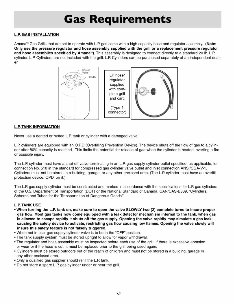
AmanaTM Gas Grills that are set to operate with L.P. gas come with a high capacity hose and regulator assembly. (Note:Only use the pressure regulator and hose assembly supplied with the grill or a replacement pressure regulatorand hose assemblies specified by AmanaTM). This assembly is designed to connect directly to a standard 20 lb. L.P.cylinder. L.P. Cylinders are not included with the grill. L.P. Cylinders can be purchased separately at an independent deal-er.
L.P. TANK INFORMATION
Never use a dented or rusted L.P. tank or cylinder with a damaged valve.
L.P. cylinders are equipped with an O.P.D (Overfilling Prevention Device). The device shuts off the flow of gas to a cylin-der after 80% capacity is reached. This limits the potential for release of gas when the cylinder is heated, averting a fireor possible injury.
The L.P. cylinder must have a shut-off valve terminating in an L.P. gas supply cylinder outlet specified, as applicable, forconnection No. 510 in the standard for compressed gas cylinder valve outlet and inlet connection ANSI/CGA-V-1.Cylinders must not be stored in a building, garage, or any other enclosed area. (The L.P. cylinder must have an overfillprotection device, OPD, on it.)
The L.P. gas supply cylinder must be constructed and marked in accordance with the specifications for L.P. gas cylindersof the U.S. Department of Transportation (DOT) or the National Standard of Canada, CAN/CAS-B339, “Cylinders,Spheres and Tubes for the Transportation of Dangerous Goods.”
L.P. TANK USE• When turning the L.P. tank on, make sure to open the valve SLOWLY two (2) complete turns to insure proper
gas flow. Most gas tanks now come equipped with a leak detector mechanism internal to the tank, when gasis allowed to escape rapidly it shuts off the gas supply. Opening the valve rapidly may simulate a gas leak,causing the safety device to activate, restricting gas flow causing low flames. Opening the valve slowly willinsure this safety feature is not falsely triggered.
• When not in use, gas supply cylinder valve is to be in the “OFF” position.• The tank supply system must be stored upright to allow for vapor withdrawal.• The regulator and hose assembly must be inspected before each use of the grill. If there is excessive abrasion
or wear or if the hose is cut, it must be replaced prior to the grill being used again.• Cylinders must be stored outdoors out of the reach of children and must not be stored in a building, garage or
any other enclosed area.• Only a qualified gas supplier should refill the L.P. tank.• Do not store a spare L.P. gas cylinder under or near the grill.
LP hose/ regulatorsupplied
with com-plete grilland cart.
(Type 1 connector)
Pre Operation Leak Testing
19
GENERAL INFORMATION
Although all internal gas connections on the grill are leak tested prior to shipment, a complete gas tightness check mustbe performed at the installation site due to possible shifting during shipment, installation or excessive pressure unknow-ingly being applied to the unit. Periodically check the whole system for leaks and immediately check the system if thesmell of gas is detected.
BEFORE TESTING
Do not smoke while leak testing. Extinguish all open flames. Never leak test with an open flame.
Mix a solution of equal parts mild detergent or liquid soap and water.
TESTING
1. Turn off the burner control knobs.2. Turn the top knob of the fuel supply cylinder counterclockwise (right to left) two (2) rotations to open.3. Apply the soap solution to connections of the fuel supply assembly. If no soap bubbles appear, there is no gas leak. If
bubbles form at the connections, a leak is detected. If a leak is detected, immediately turn off the gas supply, tightenany leaking fittings, turn gas on, and repeat steps 1-3.
4. Turn off the knob on the fuel supply cylinder.5. Turn on the burner control knobs for a moment to release the pressure in the hose, then turn the control knobs back off.6. Wash off soapy solution with cold water and towel dry.
Check all gas supply fittings before each use and each time the gas supply cylinder is connected to the regulator.Have a qualified service technician leak test the grill any time a part of the gas system is replaced.
Also it is recommended to perform a leak test at least once a year whether or not the L.P. gas supply cylinder has beendisconnected.
NOTE: When leak testing this appliance, make sure to test and tighten all loose connections, including the side burner.A slight leak in the system can result in a low flame, or hazardous condition. Most L.P. gas tanks now come equippedwith a leak detector mechanism internal to the tank, when gas is allowed to escape rapidly it shuts off the gassupply. A leak may significantly reduce the gas flow making the grill difficult to light or causing low flames.
NOTE: If you cannot stop a gas leak turn off the gas supply and call your local gas company or the dealer youpurchased the appliance from. If necessary, replace the faulty part with the manufacturer’s recommendedreplacement part. A slight leak could cause a fire.

BEFORE LIGHTING
Important! Before Lighting...
Check the gas supply line for cuts, wear or abrasion.
Always keep your face and body as far away from thegrill as possible when lighting.
GRILL BURNER LIGHTING
Lighting the Grill with electronic igniter
1. Make sure all control knobs are in the “OFF” position.
2. Open the gas supply valve located on top of your L.P.tank.
ATTENTION: When turning the L.P. tank on, make sureto open the valve very SLOWLY two (2) complete turnsto insure proper gas flow.
3. Always open the hood before attempting to light.
4. Push and turn one of the control knobs counter clock-wise to the “HIGH” position and immediately press theelectronic igniter button. You will hear a snappingsound. It may be necessary to hold the electronicstarter button for about 4 seconds. (See Fig. 60)
NOTE: If the burner does not light in 4 seconds, turnthe knob to the “OFF” position and wait 5 minutesbefore trying again.
5. Repeat above steps to light remaining burners.
Match Lighting
If by chance the electronic igniter does not light the burn-er, the burner may be lit with a match. Keep your face asfar away from the grill surface as possible and place a lit,long stem match through the spaces in the grill grates tothe ports of the back crossover burner between the flavorgrids. Position the match near the burner ports and pushand turn the control knob counter clockwise to the“HIGH” position. (See Fig. 61-62)
Note: If the grill will not light after several attemptssee the trouble-shooting section of this manual. Turnthe control knobs to the OFF position when not inuse.
Fig. 60
Fig. 61
Fig. 62
Lighting the Grill
20
Do not attempt to “Light” the grill ifthe odor of gas is present!!
Crossover Burner

Using the Grill
21
GRILL LOCATION
Do not use the grill in garages, breezeways, sheds or any enclosed area. Never operate the grill inenclosed areas as this could lead to a carbon monoxide buildup, which could result in injury ordeath. Place the grill on a level surface. Avoid moving the grill while it is operation.
NOTE: The grill will operate best if it is not facing directly into the wind.
Clearance to combustible construction - A minimum of 12” from the sides and back must be maintained from the gas grillabove and below the cooking surface to adjacent vertical combustible construction.
Clearance to non-combustible construction - A minimum of 6” clearance from the back of the grill to non-combustibleconstruction is required for the lid to fully open.
Storage of an outdoor gas cooking appliance indoor is permissible only if the cylinder is disconnected and removed fromthe appliance.
GENERAL RULES
Do not leave the grill unattended while cooking!
1. Make sure the grill has been leak tested and is properly located.2. Light the grill burners using the instructions provided in this manual.3. Turn the control knobs to desired temperature “High, Medium, or Low” and preheat the grill for 10 minutes
before cooking.4. Adjust heat settings to meet your cooking needs for desired results.5. Allow grill to cool down, wipe off any splatters or grease and clean the drip tray as needed.6. Do not put a cover on the grill while it is still hot as it could start a fire.
Keep any electrical supply cords and the fuel supply hose away from any heatedsurfaces.!
SIDE BURNER LIGHTING
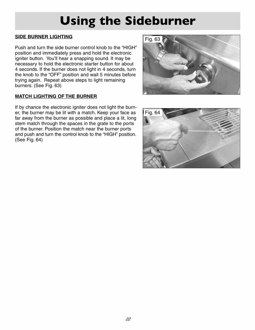
Push and turn the side burner control knob to the “HIGH”position and immediately press and hold the electronicigniter button. You’ll hear a snapping sound. It may benecessary to hold the electronic starter button for about4 seconds. If the burner does not light in 4 seconds, turnthe knob to the “OFF” position and wait 5 minutes beforetrying again. Repeat above steps to light remainingburners. (See Fig. 63)
MATCH LIGHTING OF THE BURNER
If by chance the electronic igniter does not light the burn-er, the burner may be lit with a match. Keep your face asfar away from the burner as possible and place a lit, longstem match through the spaces in the grate to the portsof the burner. Position the match near the burner portsand push and turn the control knob to the “HIGH” position.(See Fig. 64)
Fig. 63
Fig. 64
Using the Sideburner
22
Care and Maintenance
23
DRIP TRAY
The drip tray located below the grill, inside the cart, should be cleaned periodically to prevent heavy buildup of debris.
NOTE: Allow the drip tray to cool before attempting to clean.
Important: Do not leave the grill outside during inclement weather unless it is covered (cover sold separately).Rain water can collect inside of the grill, the grill cart or the drip tray if left uncovered. If the drip tray is notcleaned after use and the grill is left uncovered, the drip tray will fill with water causing grease and water to spillinto the grill cart. We recommend cleaning and storing the drip tray after every use.
COOKING GRATES
The cooking grates can be cleaned immediately after cooking is completed and after turning off the grill. Wear a barbecuemitt and scrub the cooking grates with a damp cloth. If the grill is allowed to cool down, cleaning the grates will be easierif removed from the grill and cleaned with a mild detergent.
STAINLESS STEEL
After initial usage, areas of the grill may discolor from the intense heat given off by the burners, this is normal.
Purchase a mild stainless steel cleaner and rub in the direction of the grain of the metal. Specks of grease can gather onthe surface of the stainless steel and bake on to the surface and give a worn appearance. For removal, use an non-abra-sive oven cleaner in conjunction with a stainless cleaner.
NOTE: Always scrub in the direction of the grain.NOTE: Always keep your grill covered when not in use.
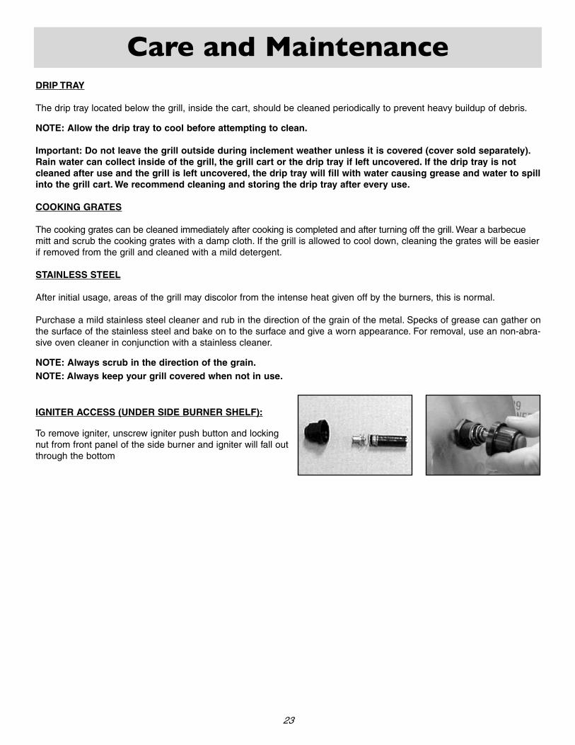
IGNITER ACCESS (UNDER SIDE BURNER SHELF):
To remove igniter, unscrew igniter push button and locking nut from front panel of the side burner and igniter will fall outthrough the bottom

Troubleshooting Your Grill
24
GENERAL TROUBLE SHOOTING
You should inspect the burners at least once a year or immediately if any of the following conditions occur:• The smell of gas.• Flames appearing mostly yellow. (some yellow at the tips is OK)• The grill will not get hot enough.• Burners make a snapping noise.• The grill heats unevenly.
SPIDER AND INSECT WARNING
Spider and insects can nest in the burners of this or any other grill and cause the gas to flow from the front of the burner.This is very dangerous condition which can cause a fire to occur behind the valve panel, thereby damaging the grill andmaking it unsafe to operate. We recommend you check the grill and remove any spiders, insects and webs at least oncea year to reduce this risk.
BEFORE CALLING CUSTOMER SERVICE
If the grill does not function properly, use the following checklist.
PROBLEM
Grill will not light when the igniter button is pushed.
SOLUTION
Is your gas supply turned on ?
If this is an L.P. grill, is there gas in your tank ? Check your gas level.
Is one of your burners turned on? Allow up to four secondsof gas flow to ignite.
Is your igniter working? - You should hear a snapping sound when you press
the igniter?- If you hear a snapping sound can you see a spark at
the electrodes?Note - You will need to remove your cooking grates and flavor grids to see the electrodes.
Check to see if your igniter battery is installed correctlywith the negative side in.
Check your igniter battery and replace if needed.
Check for loose wire connections to the igniter or electrodes.
Check to see if debris is blocking the electrodes.
If the igniter is not working can you light the grill with a match?
Troubleshooting Your Grill
25
PROBLEM
Grill will not light with a match or low heat with dial setto "High" position.
Flame is erratic
Flare-ups
Burner flame is mostly yellow or orange, possibly in conjunction with smell of gas.
Cart door does not align properly with cart
SOLUTION
• Is your gas supply fully turned on?
• If this is an L.P. grill is there gas in your tank ? Checkyour gas level.
• If this is an L.P. grill, shut off gas supply, disconnect gasline at tank, reconnect the line to the tank.
• Make sure all the knobs are in the off position, then openthe gas supply valve on the L.P. tank very slowly 1/4 turn,then open fully (at least two full turns). Check flameheight again.
• Check to insure the gas supply line or hose is not kinked.
• If only one burner appears low, check and clean the burn-er ports if clogged or dirty.
• Check for leaks.
Note - Pre-Heating time can take from 5 to 10 minutes.
• Check gas connection- look for kinked hose.- make sure gas supply valve is fully open.
• Gas level may be low.
• Grill may be in need of cleaning.
• Check flavor grids and cooking grates for excess food orgrease build-up.
• Ensure grill is not placed directly in the path of wind.
• Be sure drip tray is clean, (do not use aluminum foil on drip tray.)
Note: Some flare-ups may be inevitable if cookinggreasy foods.
• Check the burner inlet for obstructions. Particularly at airinlets for each burner.
• Grill may be in an area that is too windy.
• Loosen the four 1/2” bolts under the grill hood that holdgrill to cart. Slide grill head left or right as needed untildoor is aligned properly. Retighten bolts.
WARNING: Move grill head gently to the left or right onthe cart! After the four bolts have been loosened, thegrill is not attached to the cart and could fall, causingdamage or physical injury.
Warranty
RMP-122-0CD1002 09/14/2005
AmanaTM warrants this grill to the original purchaser of our grills when subject to normal residential use to be free from defects in workmanship and materials for the periods listed below.
IMPORTANT: We recommend you return the warranty registration card so that you can be contacted with any questions of safety arise that could affect you. The return of the warranty registration card is not a condition for warranty coverage.
LIMITED WARRANTYComponent Warranty Period
Stainless Steel Panels: Limited LifetimeBurners: Limited 3 YearsValves, Knobs, Electronic Igniter, Other related parts Limited 1 Year
If the AmanaTM Grill does not operate properly, first thoroughly carry out the instructions providedwith the unit to ensure that the appliance is installed correctly and check the troubleshooting section in the use and care manual.
• The warranty is non-transferable.
• The warranty is for replacement of defective parts only. AmanaTM will not be responsible for dam-age resulting from accident, alteration, misuse, abuse, hostile environments, improper installationor installation not in accordance with local codes.
• This limited warranty does not cover corrosion or discoloring due to lack of maintenance, misuse,hostile environments, alterations, accidents or abuse or neglect.
• This limited warranty does not cover any scratches, dents, corrosion or discoloring by heat,abrasive and chemical cleaners nor any components used in the installation of the appliance.
If you have other questions, please contact Customer Service Hotline(800) 229-5647
LIMITED LIFETIME WARRANTY