USACE Earthquake Research & Implementation Activities · Possible Earthquake Induced Modes of...
39
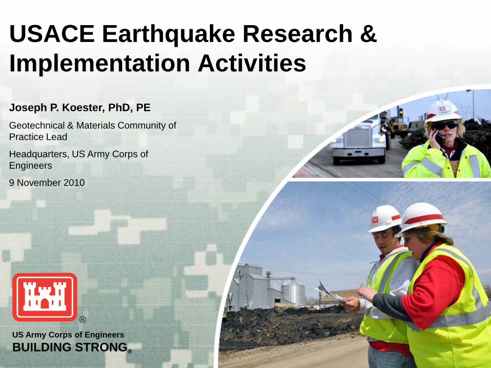
US Army Corps of Engineers BUILDING STRONG ® USACE Earthquake Research & Implementation Activities Joseph P. Koester, PhD, PE Geotechnical & Materials Community of Practice Lead Headquarters, US Army Corps of Engineers 9 November 2010
Transcript of USACE Earthquake Research & Implementation Activities · Possible Earthquake Induced Modes of...
US Army Corps of EngineersBUILDING STRONG®
USACE Earthquake Research & Implementation ActivitiesJoseph P. Koester, PhD, PEGeotechnical & Materials Community of Practice Lead
Headquarters, US Army Corps of Engineers
9 November 2010
BUILDING STRONG®
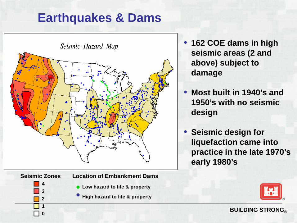
Earthquakes & Dams
• 162 COE dams in high seismic areas (2 and above) subject to damage
• Most built in 1940’s and 1950’s with no seismic design
• Seismic design for liquefaction came into practice in the late 1970’s early 1980’s
43210
Seismic Zones Location of Embankment Dams
Low hazard to life & property
High hazard to life & property
BUILDING STRONG®
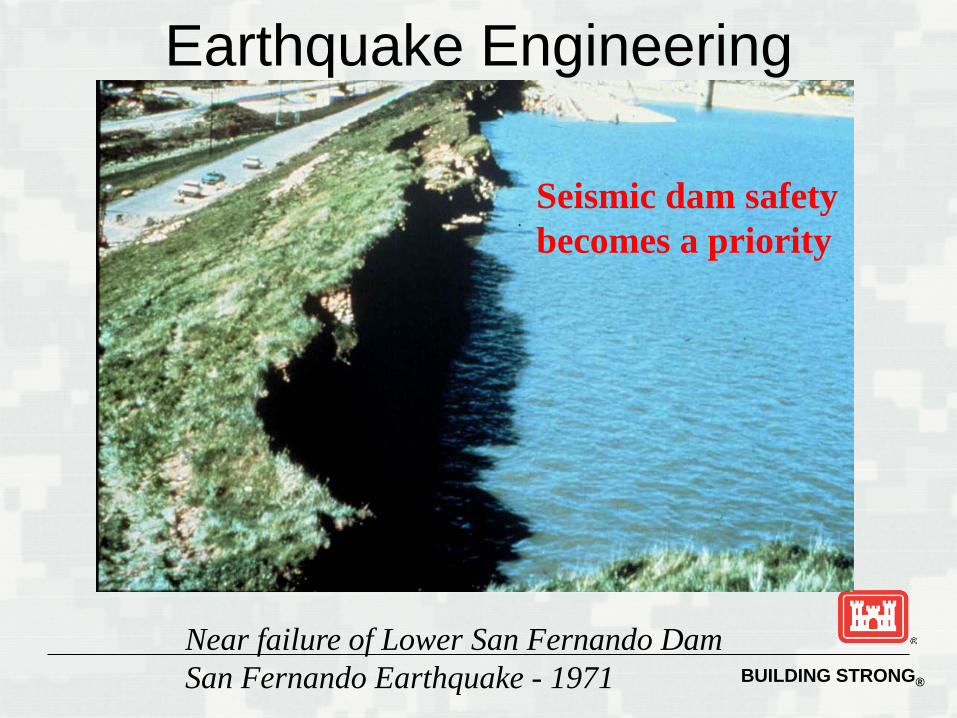
Earthquake Engineering
Near failure of Lower San Fernando DamSan Fernando Earthquake - 1971
Seismic dam safetybecomes a priority
BUILDING STRONG®
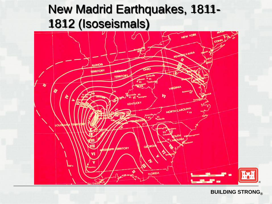
New Madrid Earthquakes, 1811-1812 (Isoseismals)
BUILDING STRONG®
Earthquake Effects Transient loading or shaking Changes material properties Settlement Liquefaction Permanent ground displacement Dynamic response
►Each thing has it own shaking response
BUILDING STRONG®
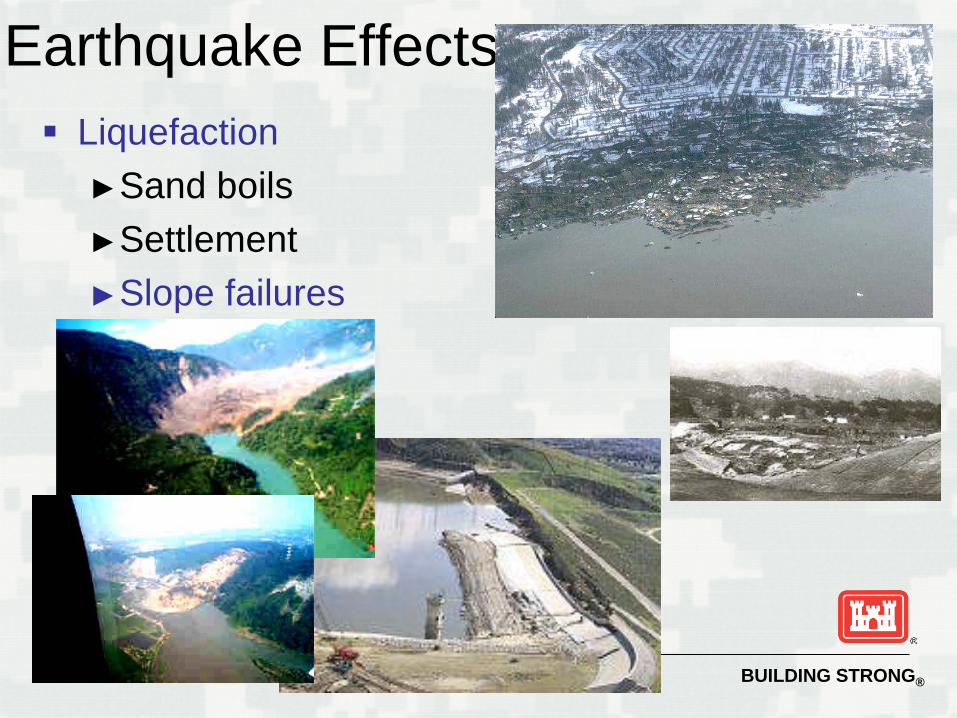
Earthquake Effects Liquefaction
►Sand boils►Settlement►Slope failures
BUILDING STRONG®
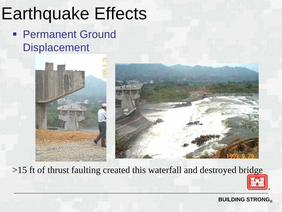
Earthquake Effects Permanent Ground
Displacement
>15 ft of thrust faulting created this waterfall and destroyed bridge
BUILDING STRONG®
What Levees Are
Permanent structures (earthen, concrete/wood/steel walls, combination) Long Intended for temporary retention of
streams during high water events Corps responsible for over 14,000 miles of
levees
BUILDING STRONG®
BUILDING STRONG®
What Levees Are Not Dams
► They are not typically zoned to withstand long-term retention/seepage
► They do not generally include deep seepage cut-off features
► They are not typically built to withstand extreme, rare loading events (e.g., earthquakes, waves or surges)
► They are very rarely designed to withstand overtopping flow
Levees are, however, expected to protect populations and property in the same manner as dams, for brief exposure time !
BUILDING STRONG®
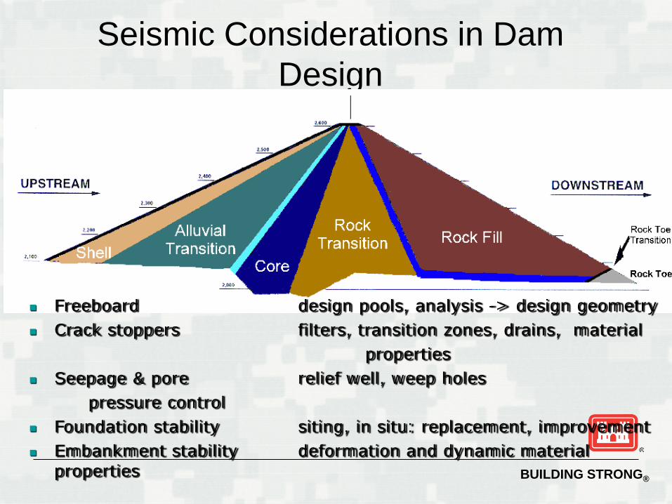
Seismic Considerations in Dam Design
Freeboard design pools, analysis -> design geometry Crack stoppers filters, transition zones, drains, material
properties Seepage & pore relief well, weep holes
pressure control Foundation stability siting, in situ: replacement, improvement Embankment stability deformation and dynamic material
properties
BUILDING STRONG®
Possible Earthquake Induced Modes of Failure
Disruption of levee by fault movement in foundation Loss of freeboard due to settlement or differential tectonic
ground movements Slope failures induced by ground motions Sliding of levee on weak foundation materials Piping failure through cracks induced by ground
movements Overtopping of levee due to seiches in waterway Overtopping of levee due to slides or rockfalls into
waterway
BUILDING STRONG®
Vulnerability Assessment
Seismic vulnerability of levees and dams are similar and are evaluated as such
► Liquefaction triggering analysis
► Seismic slope stability analysis
► Post-earthquake stability analysis
► Deformation analysis, if warranted
BUILDING STRONG®
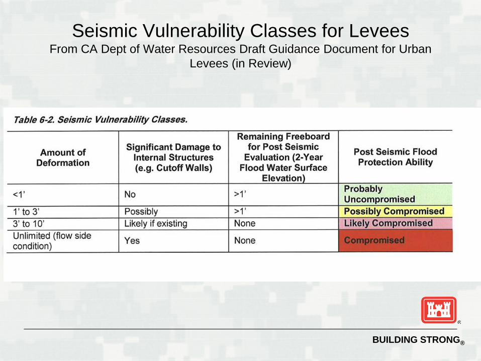
Seismic Vulnerability Classes for LeveesFrom CA Dept of Water Resources Draft Guidance Document for Urban
Levees (in Review)
BUILDING STRONG®
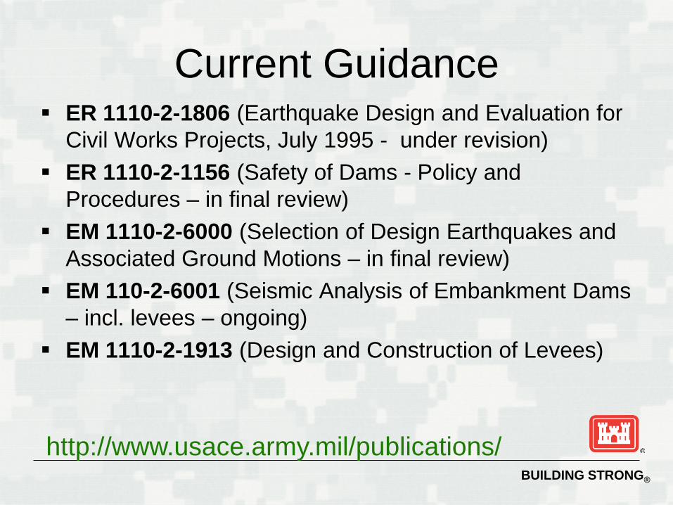
Current Guidance ER 1110-2-1806 (Earthquake Design and Evaluation for
Civil Works Projects, July 1995 - under revision) ER 1110-2-1156 (Safety of Dams - Policy and
Procedures – in final review) EM 1110-2-6000 (Selection of Design Earthquakes and
Associated Ground Motions – in final review) EM 110-2-6001 (Seismic Analysis of Embankment Dams
– incl. levees – ongoing) EM 1110-2-1913 (Design and Construction of Levees)
http://www.usace.army.mil/publications/
BUILDING STRONG®
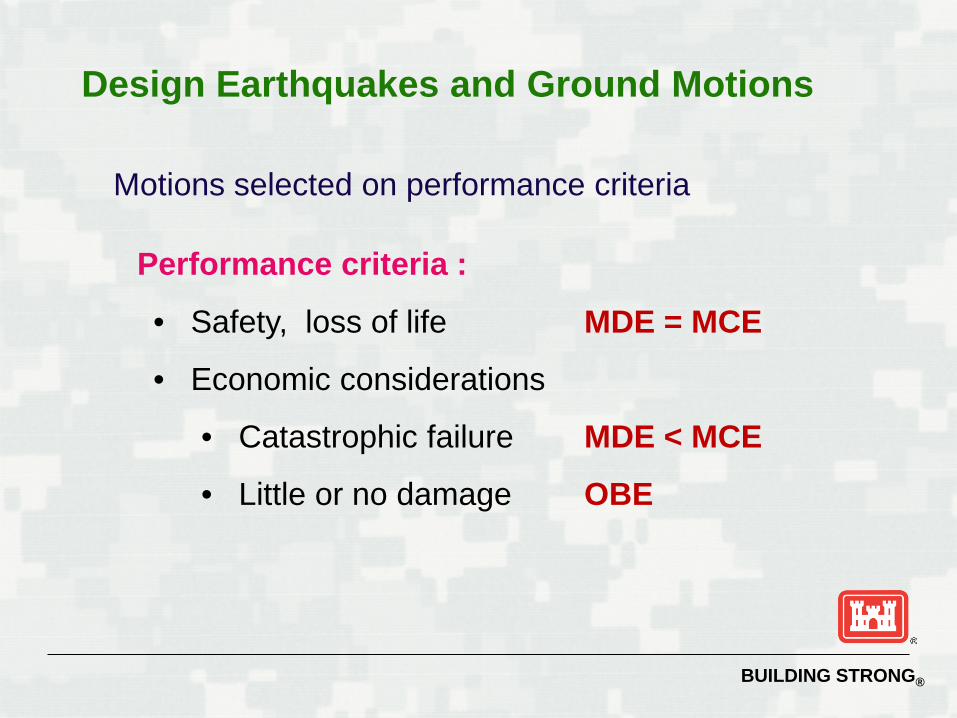
Design Earthquakes and Ground Motions
Motions selected on performance criteria
Performance criteria :
• Safety, loss of life MDE = MCE
• Economic considerations
• Catastrophic failure MDE < MCE
• Little or no damage OBE
BUILDING STRONG®
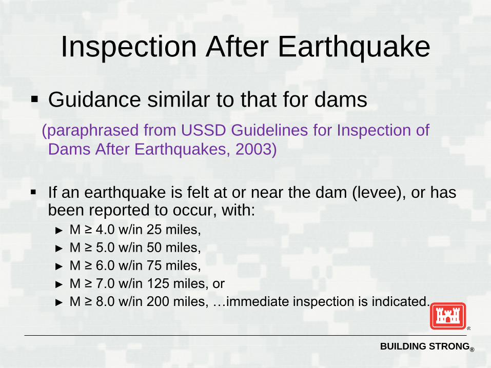
Inspection After Earthquake
Guidance similar to that for dams(paraphrased from USSD Guidelines for Inspection of Dams After Earthquakes, 2003)
If an earthquake is felt at or near the dam (levee), or has been reported to occur, with:
► M ≥ 4.0 w/in 25 miles, ► M ≥ 5.0 w/in 50 miles, ► M ≥ 6.0 w/in 75 miles, ► M ≥ 7.0 w/in 125 miles, or ► M ≥ 8.0 w/in 200 miles, …immediate inspection is indicated.
BUILDING STRONG®
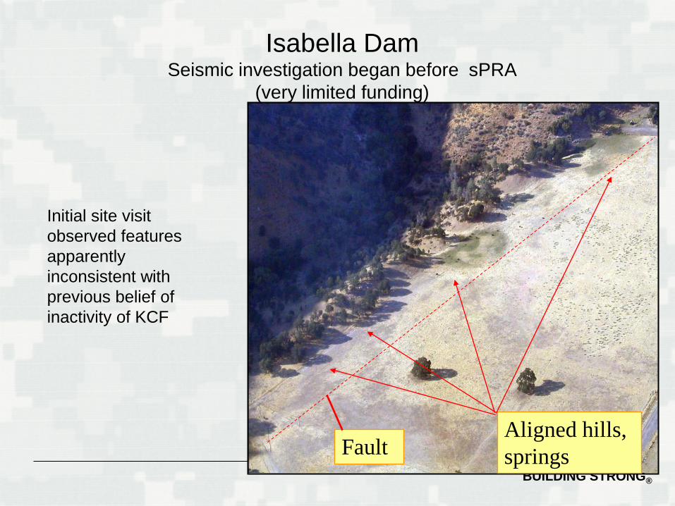
Aligned hills, springsFault
Isabella DamSeismic investigation began before sPRA
(very limited funding)
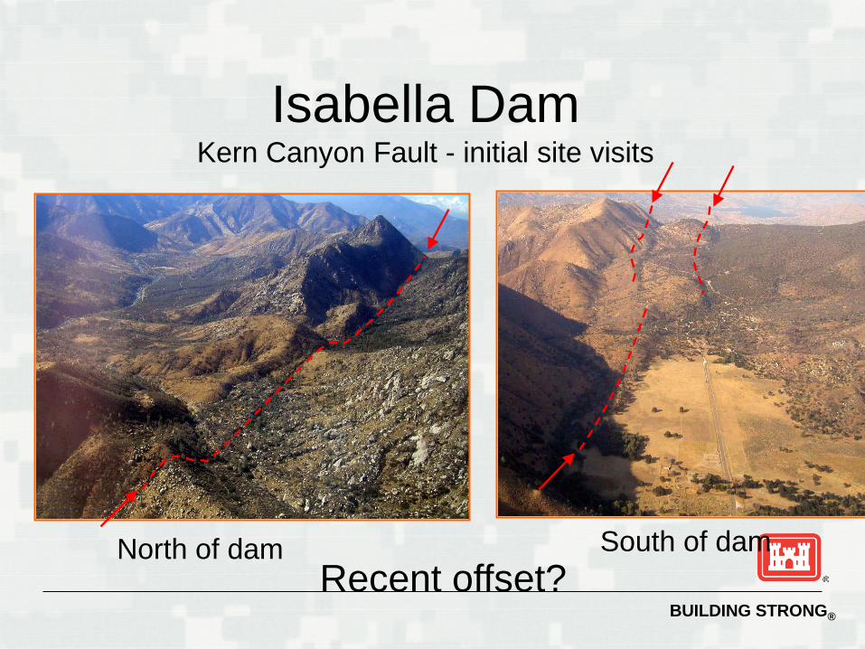
Initial site visit observed features apparently inconsistent with previous belief of inactivity of KCF
BUILDING STRONG®
Isabella DamKern Canyon Fault - initial site visits
Recent offset?North of dam South of dam
BUILDING STRONG®
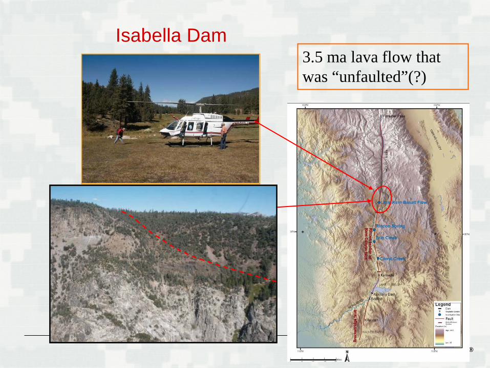
3.5 ma lava flow that was “unfaulted”(?)
Isabella Dam
BUILDING STRONG®
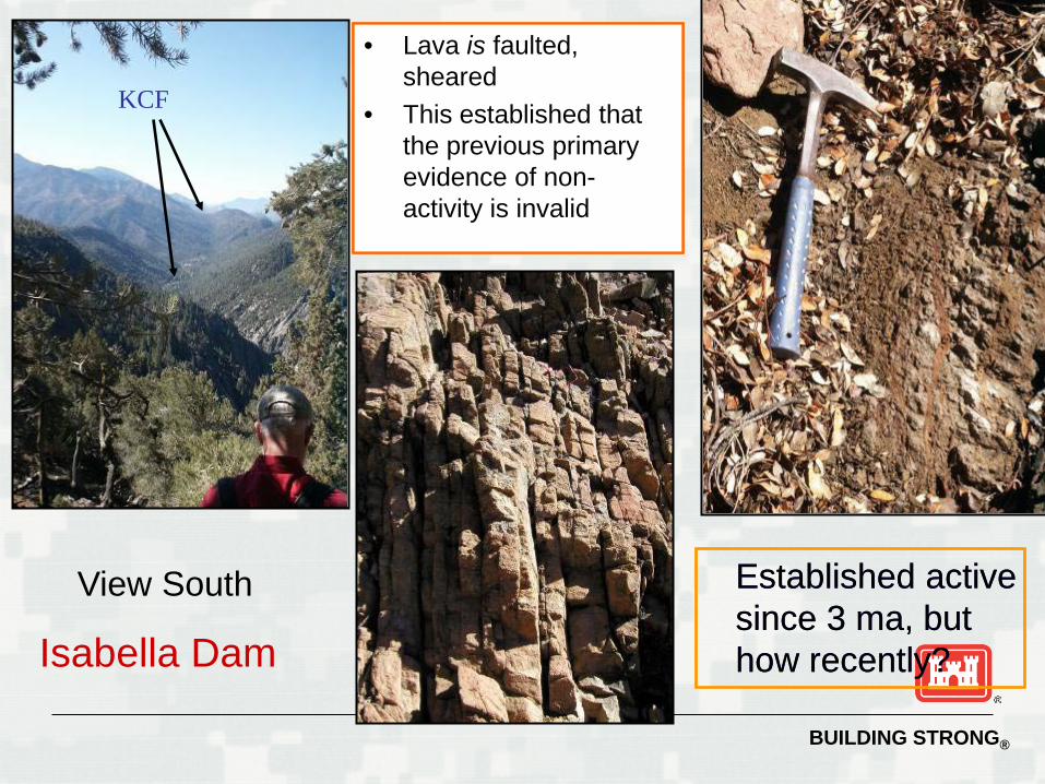
KCF
View South
• Lava is faulted, sheared
• This established that the previous primary evidence of non-activity is invalid
Established active since 3 ma, but how recently?Isabella Dam
• Lava is faulted, sheared
• This established that the previous primary evidence of non-activity is invalid
Established active since 3 ma, but how recently?
BUILDING STRONG®
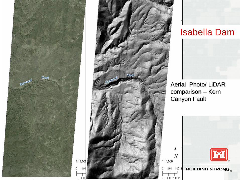
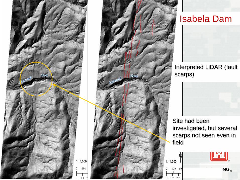
Aerial Photo/ LiDAR comparison – Kern Canyon Fault
Isabella Dam
BUILDING STRONG®
Site had been investigated, but several scarps not seen even in field
Interpreted LiDAR (fault scarps)
Isabela Dam
BUILDING STRONG®
SEISMIC SITE CHARACTERIZATION
Capable Fault
USNRC – Exhibits one or more of the following characteristics (10 CFR 100 Appendix A) :
► Movement at or near the ground surface at least once within the past 35,000 years or movement of a recurring nature within the past 500,000 years; or
► Macroseismicity instrumentally determined with records of sufficient precision to demonstrate a direct relationship with the fault; or
► A structural relationship to a capable fault according to characterizes (1) or (2) above, such that movement on one could be reasonably expected to be accompanied by movement on the other
California Division of Mines and Geology ► Surface displacement within Holocene time (about the last 10,000
years)
BUILDING STRONG®
Capable Fault
USBR ► Relative displacement within the past 100,000 years
USACE (ETL 1110-2-301 26 Aug 1983)► Movement at or near the ground surface at least once within the
past 35,000 years► Macroseismicity (>3.5 magnitude) instrumentally determined with
records of sufficient precision to demonstrate a direct relationship with the fault
► A structural relationship to a capable fault such that movement on one could be reasonably expected to be accompanied by movement on the other
► Established patterns of microseismicity that define a fault and historic macroseismicity that can be reasonably associated with that fault
SEISMIC SITE CHARACTERIZATION
BUILDING STRONG®
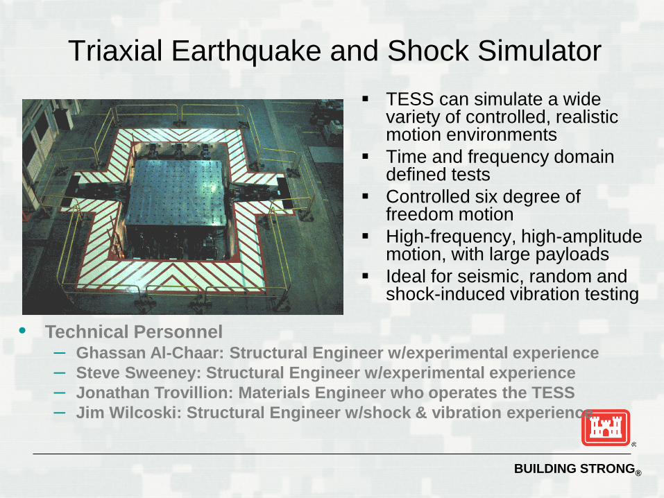
Triaxial Earthquake and Shock Simulator TESS can simulate a wide
variety of controlled, realistic motion environments
Time and frequency domain defined tests
Controlled six degree of freedom motion
High-frequency, high-amplitude motion, with large payloads
Ideal for seismic, random and shock-induced vibration testing
• Technical Personnel– Ghassan Al-Chaar: Structural Engineer w/experimental experience– Steve Sweeney: Structural Engineer w/experimental experience– Jonathan Trovillion: Materials Engineer who operates the TESS– Jim Wilcoski: Structural Engineer w/shock & vibration experience
BUILDING STRONG®
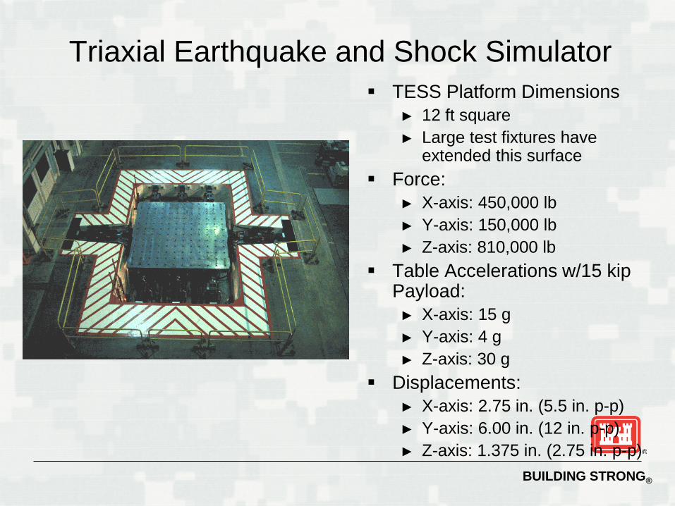
Triaxial Earthquake and Shock Simulator TESS Platform Dimensions
► 12 ft square► Large test fixtures have
extended this surface Force:
► X-axis: 450,000 lb► Y-axis: 150,000 lb► Z-axis: 810,000 lb
Table Accelerations w/15 kip Payload:
► X-axis: 15 g► Y-axis: 4 g► Z-axis: 30 g
Displacements:► X-axis: 2.75 in. (5.5 in. p-p)► Y-axis: 6.00 in. (12 in. p-p)► Z-axis: 1.375 in. (2.75 in. p-p)
BUILDING STRONG®
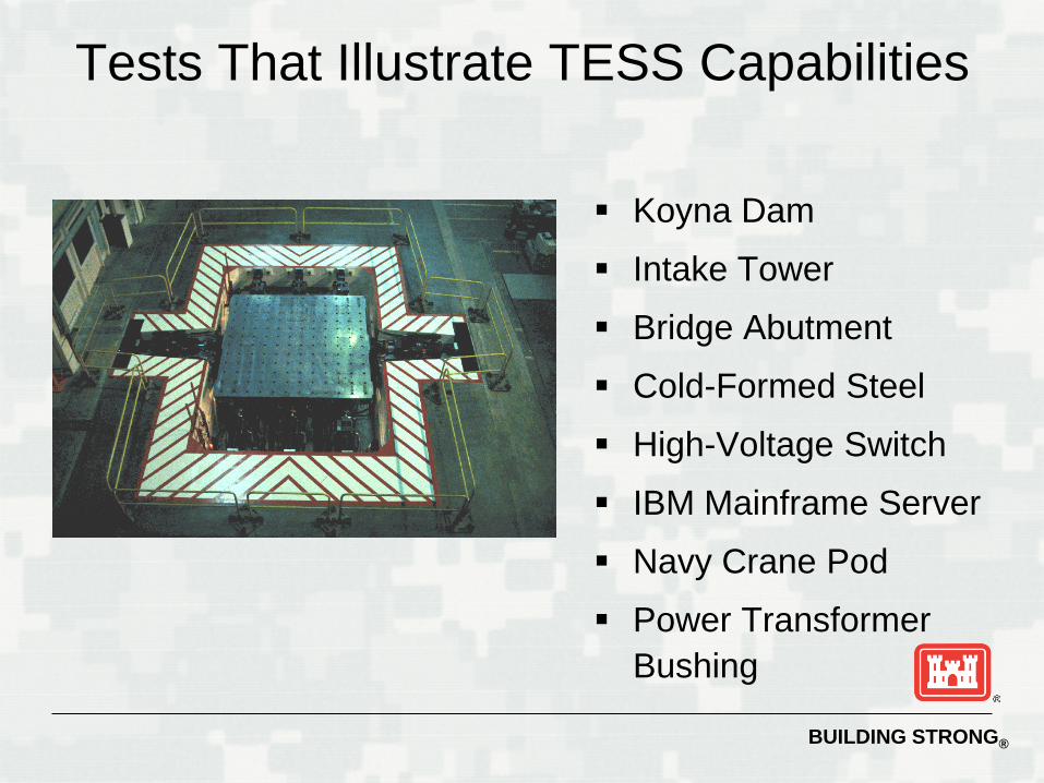
Tests That Illustrate TESS Capabilities
Koyna Dam
Intake Tower
Bridge Abutment
Cold-Formed Steel
High-Voltage Switch
IBM Mainframe Server
Navy Crane Pod
Power Transformer Bushing
BUILDING STRONG®
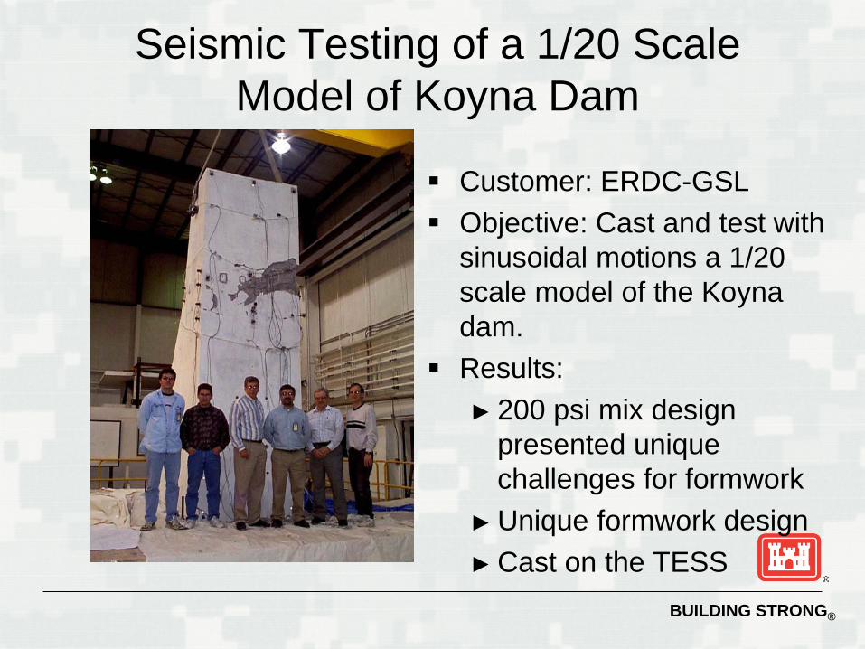
Seismic Testing of a 1/20 Scale Model of Koyna Dam
Customer: ERDC-GSL Objective: Cast and test with
sinusoidal motions a 1/20 scale model of the Koyna dam.
Results: ► 200 psi mix design
presented unique challenges for formwork
► Unique formwork design ► Cast on the TESS
BUILDING STRONG®
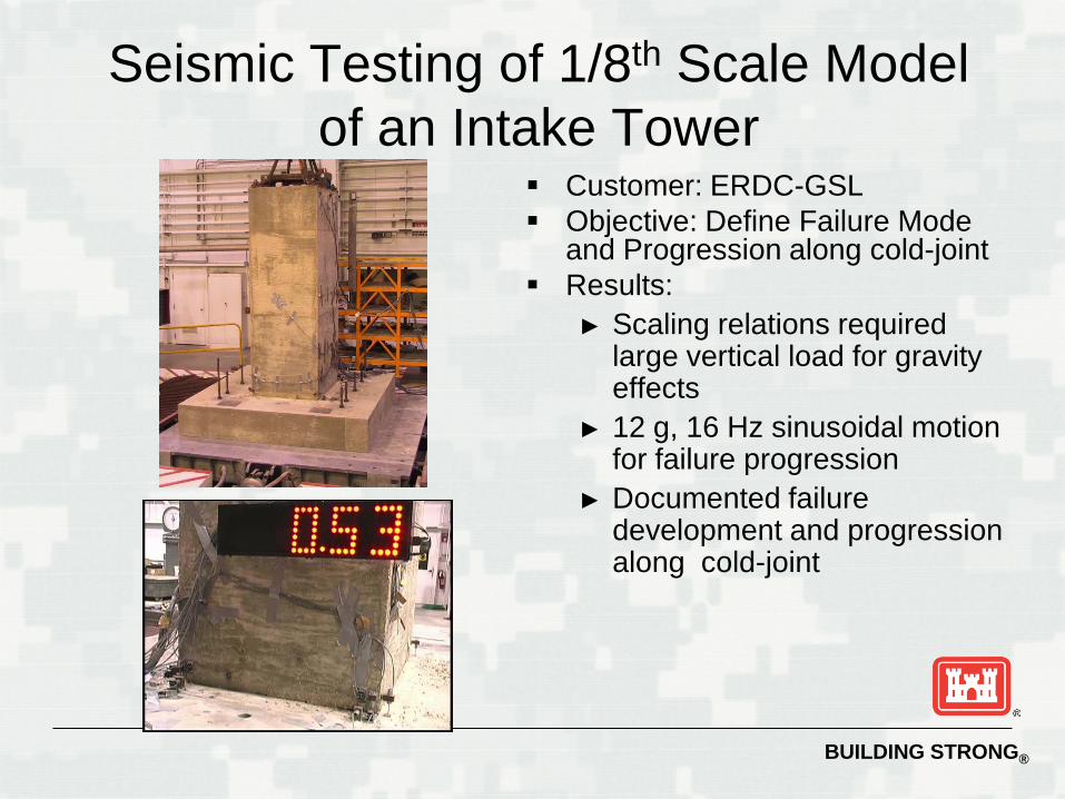
Seismic Testing of 1/8th Scale Model of an Intake Tower
Customer: ERDC-GSL Objective: Define Failure Mode
and Progression along cold-joint Results:
► Scaling relations required large vertical load for gravity effects
► 12 g, 16 Hz sinusoidal motion for failure progression
► Documented failure development and progression along cold-joint
BUILDING STRONG®
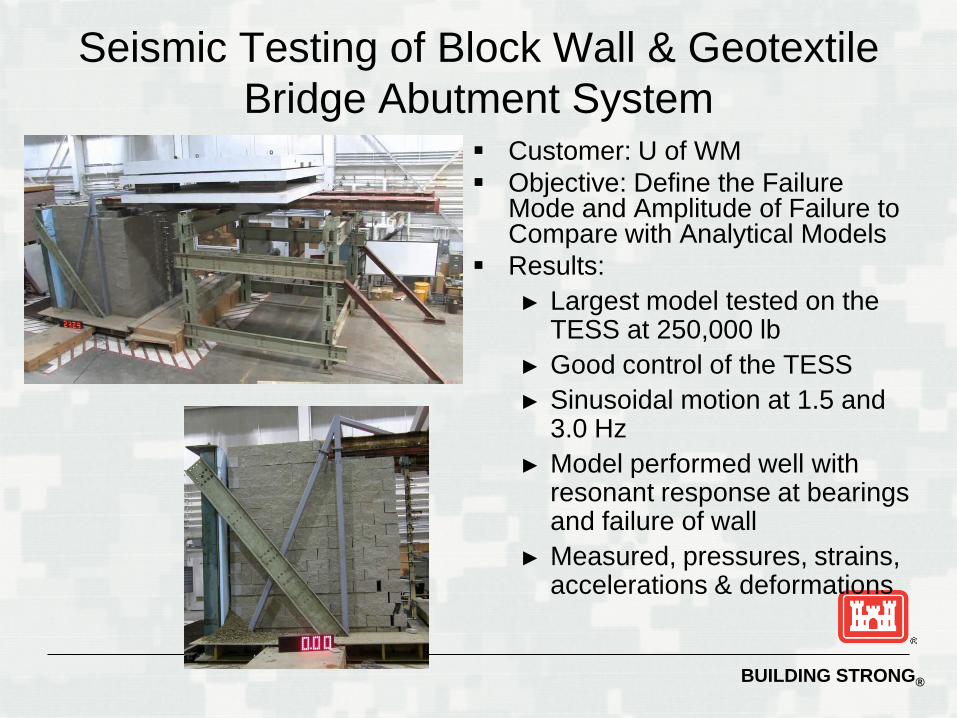
Seismic Testing of Block Wall & Geotextile Bridge Abutment System
Customer: U of WM Objective: Define the Failure
Mode and Amplitude of Failure to Compare with Analytical Models
Results: ► Largest model tested on the
TESS at 250,000 lb► Good control of the TESS► Sinusoidal motion at 1.5 and
3.0 Hz ► Model performed well with
resonant response at bearings and failure of wall
► Measured, pressures, strains, accelerations & deformations
BUILDING STRONG®
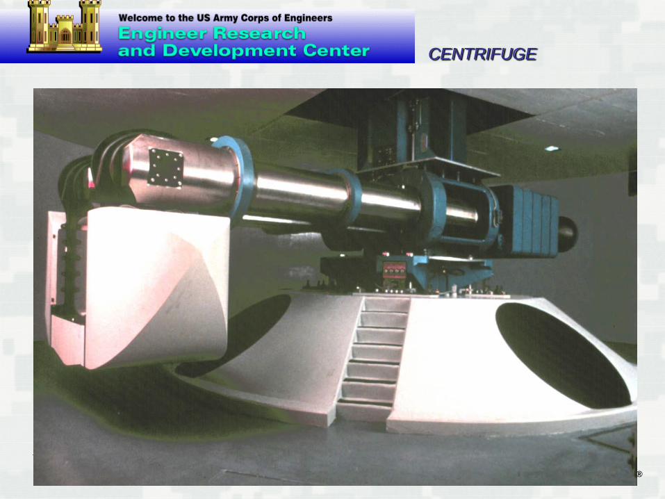
CENTRIFUGE
BUILDING STRONG®
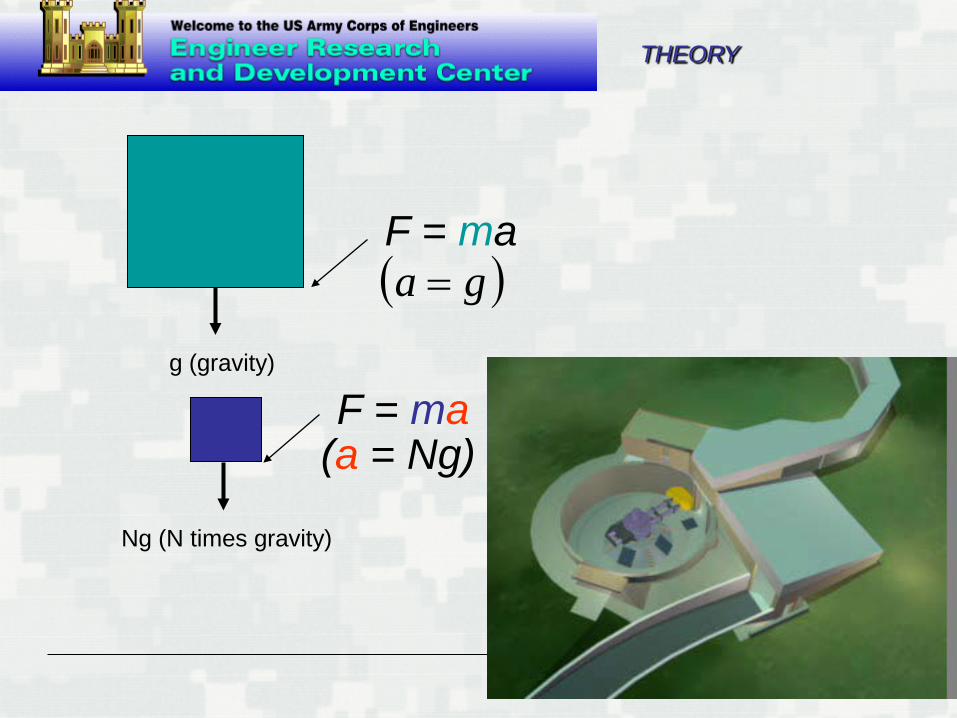
Ng (N times gravity)
g (gravity)
( )ga =F = ma
F = ma(a = Ng)
THEORY
BUILDING STRONG®
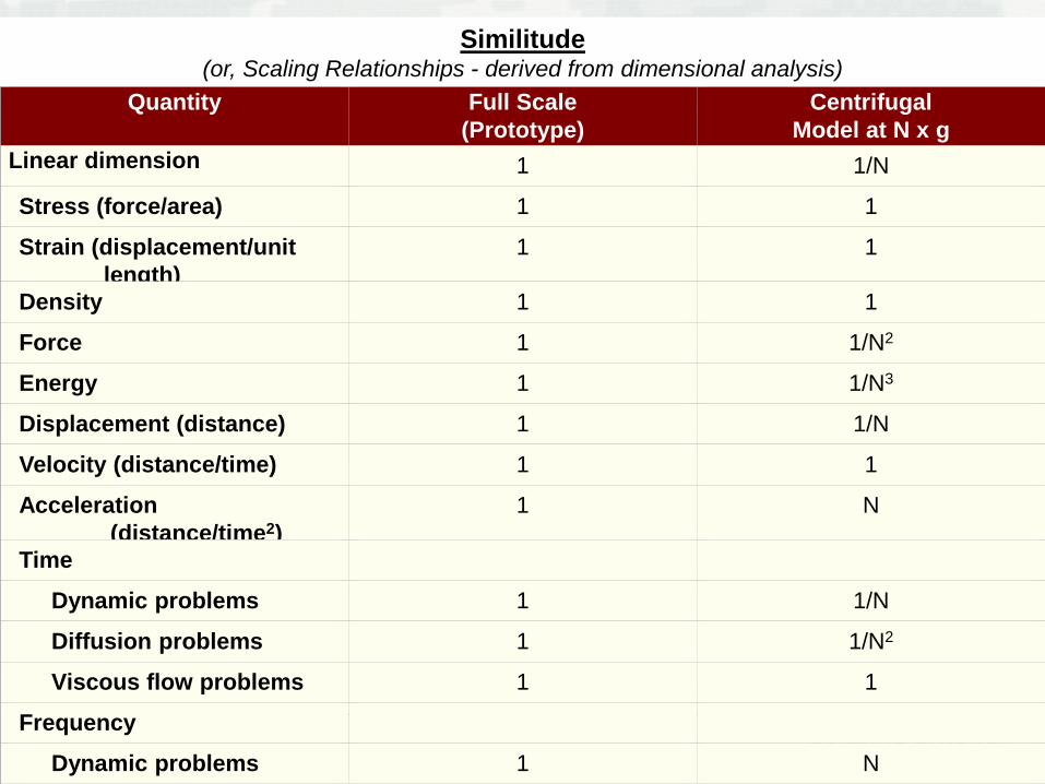
Similitude(or, Scaling Relationships - derived from dimensional analysis)
Quantity Full Scale(Prototype)
CentrifugalModel at N x g
Linear dimension 1 1/N
Stress (force/area) 1 1
Strain (displacement/unitlength)
1 1
Density 1 1
Force 1 1/N2
Energy 1 1/N3
Displacement (distance) 1 1/N
Velocity (distance/time) 1 1
Acceleration(distance/time2)
1 N
Time
Dynamic problems 1 1/N
Diffusion problems 1 1/N2
Viscous flow problems 1 1
Frequency
Dynamic problems 1 N
BUILDING STRONG®
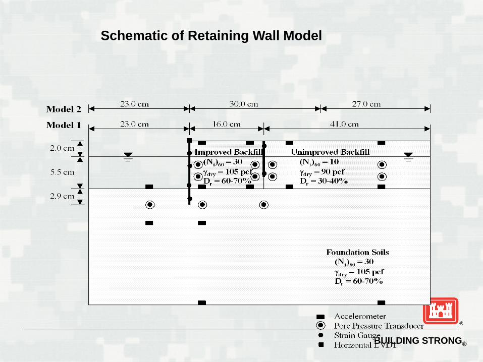
Schematic of Retaining Wall Model
BUILDING STRONG®
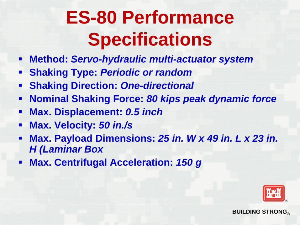
ES-80 Performance Specifications
Method: Servo-hydraulic multi-actuator system Shaking Type: Periodic or random Shaking Direction: One-directional Nominal Shaking Force: 80 kips peak dynamic force Max. Displacement: 0.5 inch Max. Velocity: 50 in./s Max. Payload Dimensions: 25 in. W x 49 in. L x 23 in.
H (Laminar Box Max. Centrifugal Acceleration: 150 g
BUILDING STRONG®
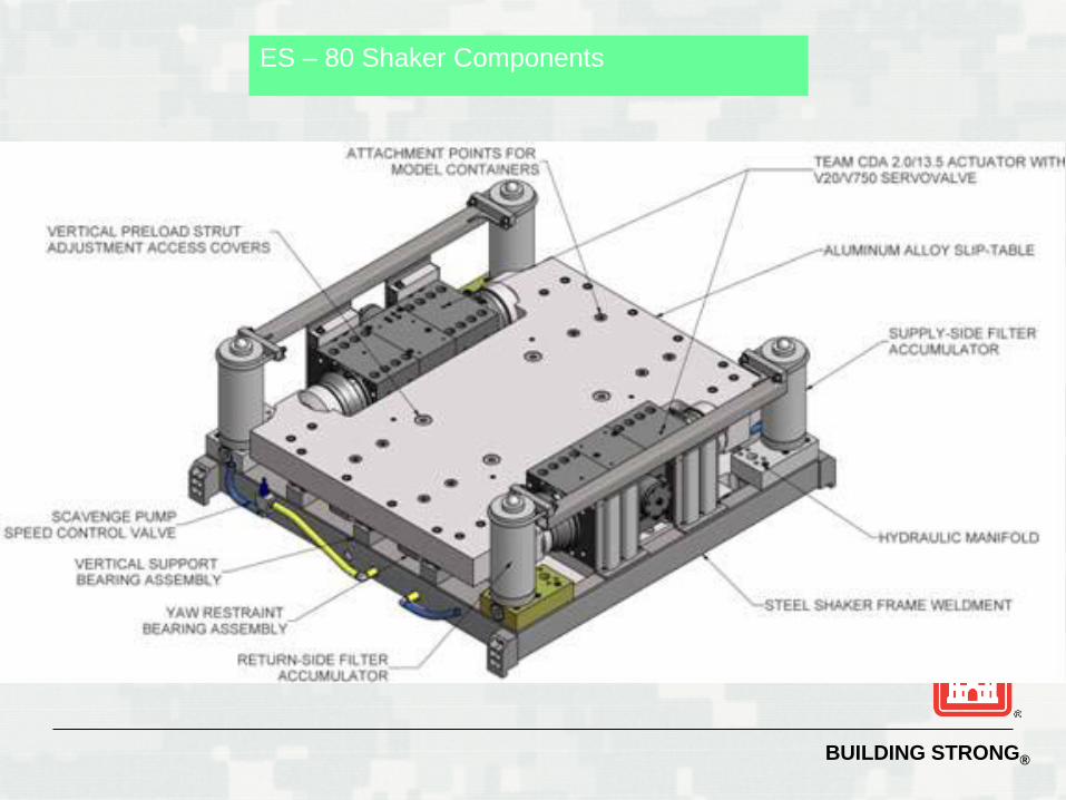
ES – 80 Shaker Components
BUILDING STRONG®
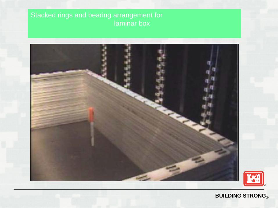
Stacked rings and bearing arrangement forlaminar box
BUILDING STRONG®
Summary
Stresses in a centrifuge model equal those in the prototype Earthquakes and other dynamic loads may
be replicated on models The ES-80 shaker provides controllable
dynamic loads on the world’s most powerful centrifuge platform