us3344i - ATEN
29
US3344I 4 x 4 USB 3.1 Gen 1 Industrial Hub Switch User Manual
Transcript of us3344i - ATEN
US3344I4 x 4 USB 3.1 Gen 1 Industrial Hub SwitchUser Manual
US3344I User Manual
ii
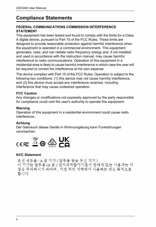
Compliance StatementsFEDERAL COMMUNICATIONS COMMISSION INTERFERENCE STATEMENT This equipment has been tested and found to comply with the limits for a Class A digital device, pursuant to Part 15 of the FCC Rules. These limits are designed to provide reasonable protection against harmful interference when the equipment is operated in a commercial environment. This equipment generates, uses, and can radiate radio frequency energy and, if not installed and used in accordance with the instruction manual, may cause harmful interference to radio communications. Operation of this equipment in a residential area is likely to cause harmful interference in which case the user will be required to correct the interference at his own expense.The device complies with Part 15 of the FCC Rules. Operation is subject to the following two conditions: (1) this device may not cause harmful interference, and (2) this device must accept any interference received, including interference that may cause undesired operation.
FCC Caution Any changes or modifications not expressly approved by the party responsible for compliance could void the user's authority to operate this equipment.
WarningOperation of this equipment in a residential environment could cause radio interference.
AchtungDer Gebrauch dieses Geräts in Wohnumgebung kann Funkstörungen verursachen.
KCC Statement

US3344I User Manual
iii
Industry Canada StatementThis Class A digital apparatus complies with Canadian ICES-003.
RoHSThis product is RoHS compliant.

US3344I User Manual
iv
About this ManualThis user manual is provided to help you get the most from the US3344I unit. It covers all aspects of installation, configuration, and operation. An overview of the information found in the manual is provided below.
Chapter 1, Introduction introduces you to the 4x4 USB 3.1 Gen 1 Industrial Hub Switch. Its purpose, features, and panel components are presented and described.
Chapter 2, Hardware Setup describes the steps that are necessary to quickly and safely set up your installation.
Chapter 3, Settings / Port Selection explains the DIP switch options of the unit, port selection options, and serial commands of the unit.
An Appendix provides a list of safety instructions and precautions, contact information for ATEN technical support, product specifications, and other technical information.
Note:
Read this manual thoroughly and follow the installation and operation procedures carefully to prevent any damage to the unit or any connected devices.
ATEN regularly updates its product documentation for new features and fixes. For an up-to-date US3344I documentation, visit http://www.aten.com/global/en/
US3344I User Manual
v
ConventionsThis manual uses the following conventions:
Monospaced Indicates text that you should key in.
[ ] Indicates keys you should press. For example, [Enter] means to press the Enter key. If keys need to be chorded, they appear together in the same bracket with a plus sign between them: [Ctrl+Alt].
1. Numbered lists represent procedures with sequential steps.
♦ Bullet lists provide information, but do not involve sequential steps.
> Indicates selecting the option (on a menu or dialog box, for example), that comes next. For example, Start > Run means to open the Start menu, and then select Run.
Indicates critical information.
US3344I User Manual
vi
Package Contents
1 US3344I 4x4 USB 3.1 Gen 1 Industrial Hub Switch
2 USB 3.1 Gen 1 Type-B to Type-A cable 1.2M
2 USB 3.1 Gen 1 Type-B to Type-A cable 1.8M
1 remote port selector
1 mounting kit
1 terminal block adapter set (an RS-422 / RS-485 and a DC terminal block adapter)
1 power adapter (sold separately from your closest ATEN dealer)
1 user instructions
Note: Make sure that all of the components are present and in good order. If anything is missing or was damaged in shipping, contact your dealer.
US3344I User Manual
vii
Product InformationFor information about all ATEN products and how they can help you connect without limits, visit ATEN on the Web or contact an ATEN Authorized Reseller. Visit ATEN on the Web for a list of locations and telephone numbers:
User Information
Online RegistrationBe sure to register your product at our online support center:
Telephone SupportFor telephone support, call this number:
International http://www.aten.com
North America http://www.aten-usa.com
International http://eservice.aten.com
International 886-2-8692-6959
China 86-400-810-0-810
Japan 81-3-5615-5811
Korea 82-2-467-6789
North America 1-888-999-ATEN ext 49881-949-428-1111
US3344I User Manual
viii
User NoticeAll information, documentation, and specifications contained in this manual are subject to change without prior notification by the manufacturer. The manufacturer makes no representations or warranties, either expressed or implied, with respect to the contents hereof and specifically disclaims any warranties as to merchantability or fitness for any particular purpose. Any of the manufacturer's software described in this manual is sold or licensed as is. Should the programs prove defective following their purchase, the buyer (and not the manufacturer, its distributor, or its dealer), assumes the entire cost of all necessary servicing, repair and any incidental or consequential damages resulting from any defect in the software.
US3344I User Manual
ix
Table of ContentsCompliance Statements . . . . . . . . . . . . . . . . . . . . . . . . . . . . . . . . . . . . . . . iiAbout this Manual . . . . . . . . . . . . . . . . . . . . . . . . . . . . . . . . . . . . . . . . . . iv
Conventions . . . . . . . . . . . . . . . . . . . . . . . . . . . . . . . . . . . . . . . . . . . . . vPackage Contents . . . . . . . . . . . . . . . . . . . . . . . . . . . . . . . . . . . . . . . . . . viProduct Information . . . . . . . . . . . . . . . . . . . . . . . . . . . . . . . . . . . . . . . . . viiUser Information . . . . . . . . . . . . . . . . . . . . . . . . . . . . . . . . . . . . . . . . . . . . vii
Online Registration . . . . . . . . . . . . . . . . . . . . . . . . . . . . . . . . . . . . . . . viiUser Notice . . . . . . . . . . . . . . . . . . . . . . . . . . . . . . . . . . . . . . . . . . . . .viii
Table of Contents . . . . . . . . . . . . . . . . . . . . . . . . . . . . . . . . . . . . . . . . . . . ix
1. IntroductionOverview . . . . . . . . . . . . . . . . . . . . . . . . . . . . . . . . . . . . . . . . . . . . . . . . . . . 1Features . . . . . . . . . . . . . . . . . . . . . . . . . . . . . . . . . . . . . . . . . . . . . . . . . . . 2Components . . . . . . . . . . . . . . . . . . . . . . . . . . . . . . . . . . . . . . . . . . . . . . . . 3
2. Hardware SetupMounting . . . . . . . . . . . . . . . . . . . . . . . . . . . . . . . . . . . . . . . . . . . . . . . . . . . 5
Rack Mounting . . . . . . . . . . . . . . . . . . . . . . . . . . . . . . . . . . . . . . . . . . . 6Wall Mounting . . . . . . . . . . . . . . . . . . . . . . . . . . . . . . . . . . . . . . . . . . . . 6
Connecting the Unit . . . . . . . . . . . . . . . . . . . . . . . . . . . . . . . . . . . . . . . . . . 7RS-422 / RS-485 Terminal Block Connection. . . . . . . . . . . . . . . . . . . . . . . 8
3. Settings / Port SelectionDIP Switch Mode Selection. . . . . . . . . . . . . . . . . . . . . . . . . . . . . . . . . . . . . 9Firmware Upgrade / Select Baud Rate . . . . . . . . . . . . . . . . . . . . . . . . . . 10
Baud Rate . . . . . . . . . . . . . . . . . . . . . . . . . . . . . . . . . . . . . . . . . . . . . . 10Port Selection . . . . . . . . . . . . . . . . . . . . . . . . . . . . . . . . . . . . . . . . . . . . . . 11RS-422 / RS-485 Port Selection . . . . . . . . . . . . . . . . . . . . . . . . . . . . . . . . 11
Appendix Safety Instructions. . . . . . . . . . . . . . . . . . . . . . . . . . . . . . . . . . . . . . . . . . . 13
General . . . . . . . . . . . . . . . . . . . . . . . . . . . . . . . . . . . . . . . . . . . . . . . . 13Rack Mounting . . . . . . . . . . . . . . . . . . . . . . . . . . . . . . . . . . . . . . . . . . 15
Technical Support . . . . . . . . . . . . . . . . . . . . . . . . . . . . . . . . . . . . . . . . . . 16International . . . . . . . . . . . . . . . . . . . . . . . . . . . . . . . . . . . . . . . . . . . . 16
Specifications . . . . . . . . . . . . . . . . . . . . . . . . . . . . . . . . . . . . . . . . . . . . . . 17Limited Warranty . . . . . . . . . . . . . . . . . . . . . . . . . . . . . . . . . . . . . . . . . . . 19

US3344I User Manual
x
This Page Intentionally Left Blank
1
Chapter 1Introduction
Overview
The US3344I is a 4-port USB3.1 Gen1 Industrial Switch that enables 4 computers to share and use USB3.1 Gen1 devices such as keyboard, mouse and other peripheral devices. The peripheral focus can be manually given to a particular computer by using pushbutton connected to the switch.
It eliminates the cost to implement the complicated redundant systems and equipment for each computer. The US3344I chassis and rack mountable design is suitable for any industrial environment. For extra convenience, it features an external remote control port that can simplify cabling layout via traditional RS-422 / RS-485 signals.
The US3344I allows for a neat and tidy installation –The USB cables are bundled to save the extra cost of purchasing USB cables.
US3344I User Manual
2
Features
Enables four computers to share USB peripheral up to four devices Supports USB 3.1 Gen1 specification, maximum data transfer rates up to
5Gbps Multiplatform support - Windows, Mac and Linux LED indicators display port focus Metal mechanical cassis with wall mountable designs Supports aftermarket USB M2 screw locking cable Supports port selection via remote controller or RS-422/RS-485 link
through 5-pin terminal block Hot pluggable Supports DC 9-24V power input by terminal block Supports Battery Charging V1.2 and over current protection
Chapter 1. Introduction
3
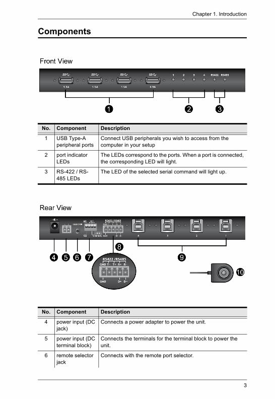
Components
No. Component Description
1 USB Type-A peripheral ports
Connect USB peripherals you wish to access from the computer in your setup
2 port indicator LEDs
The LEDs correspond to the ports. When a port is connected, the corresponding LED will light.
3 RS-422 / RS-485 LEDs
The LED of the selected serial command will light up.
No. Component Description
4 power input (DC jack)
Connects a power adapter to power the unit.
5 power input (DC terminal block)
Connects the terminals for the terminal block to power the unit.
6 remote selector jack
Connects with the remote port selector.
US3344I User Manual
4
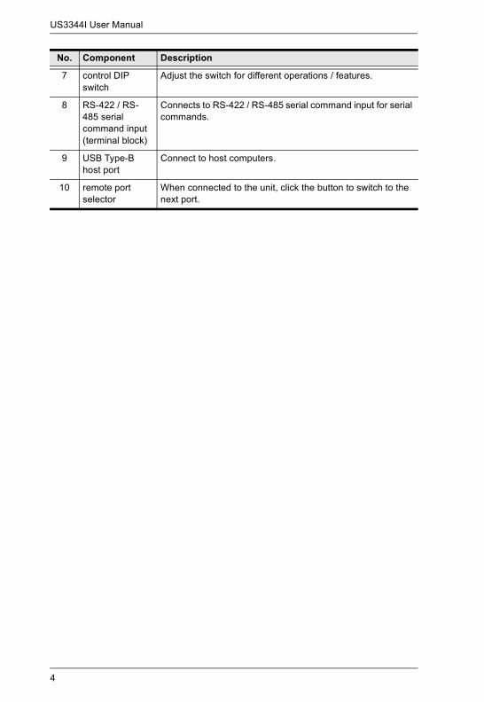
7 control DIP switch
Adjust the switch for different operations / features.
8 RS-422 / RS-485 serial command input (terminal block)
Connects to RS-422 / RS-485 serial command input for serial commands.
9 USB Type-B host port
Connect to host computers.
10 remote port selector
When connected to the unit, click the button to switch to the next port.
No. Component Description
5
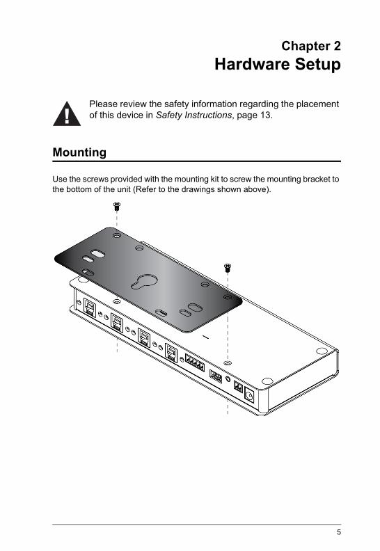
Chapter 2Hardware Setup
Mounting
Use the screws provided with the mounting kit to screw the mounting bracket to the bottom of the unit (Refer to the drawings shown above).
Please review the safety information regarding the placement of this device in Safety Instructions, page 13.
US3344I User Manual
6
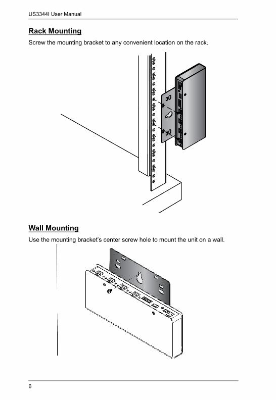
Rack MountingScrew the mounting bracket to any convenient location on the rack.
Wall MountingUse the mounting bracket’s center screw hole to mount the unit on a wall.
Chapter 2. Hardware Setup
7
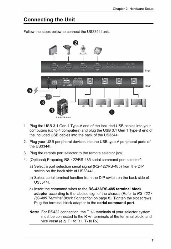
Connecting the Unit
Follow the steps below to connect the US3344I unit.
1. Plug the USB 3.1 Gen 1 Type-A end of the included USB cables into your computers (up to 4 computers) and plug the USB 3.1 Gen 1 Type-B end of the included USB cables into the back of the US3344I
2. Plug your USB peripheral devices into the USB type-A peripheral ports of the US3344I.
3. Plug the remote port selector to the remote selector jack.
4. (Optional) Preparing RS-422/RS-485 serial command port selector*:
a) Select a port selection serial signal (RS-422/RS-485) from the DIP switch on the back side of US3344I.
b) Select serial terminal function from the DIP switch on the back side of US3344I.
c) Insert the command wires to the RS-422/RS-485 terminal block adapter according to the labeled sign of the chassis (Refer to RS-422 / RS-485 Terminal Block Connection on page 8). Tighten the slot screws. Plug the terminal block adapter to the serial command port.
Note: For RS422 connection, the T +/- terminals of your selector system must be connected to the R +/- terminals of the terminal block, and vice versa (e.g. T+ to R+, T- to R-).
1
3
5
4
2
RS-422/RS485
Front
Rear
US3344I User Manual
8
5. Prepare a power input by either:
a) Connecting the DC terminal block for power input**: Insert DC + and - wires (9 to 24V DC) to the DC terminal block adapter according to the labeled sign. Tighten the slot screws. Plug the terminal block adapter to US3344I; Or
b) (Optional) Connecting a power adapter*** to the DC power input jack.
*You can connect both remote port selector and serial command port selectors for port selection.
**If both power inputs are connected, power from the DC jack will be prioritized.
***Available for purchase separately from your closest ATEN dealer (Part No.: 0AD8-8012-33MG)
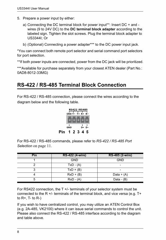
RS-422 / RS-485 Terminal Block Connection
For RS-422 / RS-485 connection, please connect the wires according to the diagram below and the following table.
For RS-422 / RS-485 commands, please refer to RS-422 / RS-485 Port Selection on page 11.
For RS422 connection, the T +/- terminals of your selector system must be connected to the R +/- terminals of the terminal block, and vice versa (e.g. T+ to R+, T- to R-)
If you wish to have centralized control, you may utilize an ATEN Control Box (e.g. 2A-485, VK2100) where it can issue serial commands to control the unit. Please also connect the RS-422 / RS-485 interface according to the diagram and table above.
Pin RS-422 (4-wire) RS-485 (2-wire)1 GND GND2 TxD - (A) -3 TxD + (B) -4 RxD + (B) Data + (A)5 RxD - (A) Data - (B)
9
Chapter 3Settings / Port Selection
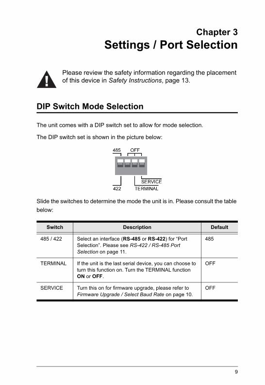
DIP Switch Mode Selection
The unit comes with a DIP switch set to allow for mode selection.
The DIP switch set is shown in the picture below:
Slide the switches to determine the mode the unit is in. Please consult the table below:
Switch Description Default
485 / 422 Select an interface (RS-485 or RS-422) for “Port Selection”. Please see RS-422 / RS-485 Port Selection on page 11.
485
TERMINAL If the unit is the last serial device, you can choose to turn this function on. Turn the TERMINAL function ON or OFF.
OFF
SERVICE Turn this on for firmware upgrade, please refer to Firmware Upgrade / Select Baud Rate on page 10.
OFF
Please review the safety information regarding the placement of this device in Safety Instructions, page 13.
US3344I User Manual
10
Firmware Upgrade / Select Baud Rate
For firmware upgrade, please do the following:
1. Power down the device by removing the power input (power adapter or DC Terminal Block).
2. Slide the SERVICE switch of DIP switch set to SERVICE.
3. Power on the device. All the LED will start flashing to indicate it is now in Upgrade Mode.
4. If you haven’t already, connect the RS-422/RS-485 Terminal to the PC for firmware upgrade. Make sure you have a terminal program (e.g. Hyperterminal) with the proper terminal settings (refer to ) and is capable of communicating with the device.
5. Download the firmware* from the link below:https://www.aten.com/global/en/products/usb-&-thunderbolt/peripheral-switches/us3344i/
Note: If you wish to use a different baud rate for serial control, you may choose a firmware version suitable for that baud rate.
6. Make sure that the terminal program of the PC is set to the baud rate of the current firmware, and run the .exe firmware upgrade you have just downloaded.
7. Restart the device by powering down the device (removing and reconnecting power input).
Baud RateWhen RS-422 / RS-485 terminal block is connected to the computer, please configure the general settings of your terminal program so you are able to communicate with the device
The default settings is shown below:
Baud Rate: 38400 Data Bit: 8 bit Parity: None Stop Bit: 1 bit Flow Control: none
Different baud rate is available with different firmware versions. If you wish to use a different baud rate for serial communication, identify the baud rate you wish to use from the link below:

Chapter 3. Settings / Port Selection
11
https://www.aten.com/global/en/products/usb-&-thunderbolt/peripheral-switches/us3344i/
Go through the steps in Firmware Upgrade / Select Baud Rate to upgrade to the new firmware / baud rate.
Port Selection
Remote Port Selector: When a remote port selector is connected, you can click the selector’s button to select a different port.
The click-to-toggle action switches ports in numeric order. If the active port is at port 4, clicking the button will switch to port 1.
RS-422 / RS-485 Port Selector: When RS-422 or RS-485 is connected, you can send serial commands to the unit to select a different port. You can send serial commands to either switch the ports in numeric order (like pressing a button on the remote port selector) or select a port directly.
RS-422 / RS-485 Port Selection
When RS-422 or RS-485 is connected, you can use serial commands to select a different port. The table below describes the serial commands and the responses:
If the unit replies with:
Command OK, the command is correct and unit action is executed.
Command Incorrect, the command is incorrect and no action is executed.
Command Variable Unit Action
sw NA Switches to the next port in the numeric order.
sw p0X X = (1, 2, 3, 4) Switches to port X.
info NA Displays firmware and hardware information.

US3344I User Manual
12
This Page Intentionally Left Blank
13
Appendix
Safety Instructions
General This product is for indoor use only. Read all of these instructions. Save them for future reference. Follow all warnings and instructions marked on the device. Do not place the device on any unstable surface (cart, stand, table, etc.). If
the device falls, serious damage will result. Do not use the device near water. Do not place the device near, or over, radiators or heat registers. The device cabinet is provided with slots and openings to allow for
adequate ventilation. To ensure reliable operation, and to protect against overheating, these openings must never be blocked or covered.
The device should never be placed on a soft surface (bed, sofa, rug, etc.) as this will block its ventilation openings. Likewise, the device should not be placed in a built in enclosure unless adequate ventilation has been provided.
Never spill liquid of any kind on the device. Unplug the device from the wall outlet before cleaning. Do not use liquid or
aerosol cleaners. Use a damp cloth for cleaning. The device should be operated from the type of power source indicated on
the marking label. If you are not sure of the type of power available, consult your dealer or local power company.
To prevent damage to your installation it is important that all devices are properly grounded.
Do not allow anything to rest on the power cord or cables. Route the power cord and cables so that they cannot be stepped on or tripped over.
Position system cables and power cables carefully; Be sure that nothing rests on any cables.
Never push objects of any kind into or through cabinet slots. They may touch dangerous voltage points or short out parts resulting in a risk of fire or electrical shock.
Do not attempt to service the device yourself. Refer all servicing to qualified service personnel.
If the following conditions occur, unplug the device from the wall outlet and bring it to qualified service personnel for repair.
US3344I User Manual
14
The power cord or plug has become damaged or frayed. Liquid has been spilled into the device. The device has been exposed to rain or water. The device has been dropped, or the cabinet has been damaged. The device exhibits a distinct change in performance, indicating a need
for service. The device does not operate normally when the operating instructions
are followed. Only adjust those controls that are covered in the operating instructions.
Improper adjustment of other controls may result in damage that will require extensive work by a qualified technician to repair.
Appendix
15
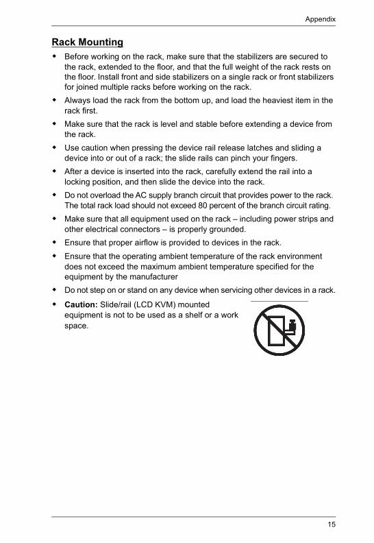
Rack Mounting Before working on the rack, make sure that the stabilizers are secured to
the rack, extended to the floor, and that the full weight of the rack rests on the floor. Install front and side stabilizers on a single rack or front stabilizers for joined multiple racks before working on the rack.
Always load the rack from the bottom up, and load the heaviest item in the rack first.
Make sure that the rack is level and stable before extending a device from the rack.
Use caution when pressing the device rail release latches and sliding a device into or out of a rack; the slide rails can pinch your fingers.
After a device is inserted into the rack, carefully extend the rail into a locking position, and then slide the device into the rack.
Do not overload the AC supply branch circuit that provides power to the rack. The total rack load should not exceed 80 percent of the branch circuit rating.
Make sure that all equipment used on the rack – including power strips and other electrical connectors – is properly grounded.
Ensure that proper airflow is provided to devices in the rack. Ensure that the operating ambient temperature of the rack environment
does not exceed the maximum ambient temperature specified for the equipment by the manufacturer
Do not step on or stand on any device when servicing other devices in a rack.
Caution: Slide/rail (LCD KVM) mounted equipment is not to be used as a shelf or a work space.

US3344I User Manual
16
Technical Support
International For online technical support – including troubleshooting, documentation,
and software updates: http://support.aten.com For telephone support, see Telephone Support, page vii:
North America
When you contact us, please have the following information ready beforehand: Product model number, serial number, and date of purchase Your computer configuration, including operating system, revision level,
expansion cards, and software Any error messages displayed at the time the error occurred The sequence of operations that led up to the error Any other information you feel may be of help
Email Support [email protected]
Online Technical Support
TroubleshootingDocumentationSoftware Updates
http://www.aten-usa.com/support
Telephone Support 1-888-999-ATEN ext 49881-949-428-1111
Appendix
17
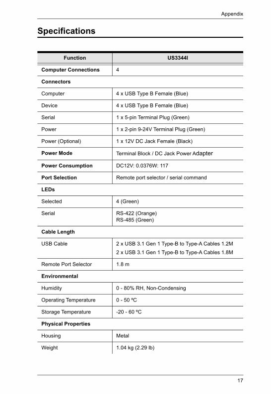
Specifications
Function US3344I
Computer Connections 4
Connectors
Computer 4 x USB Type B Female (Blue)
Device 4 x USB Type B Female (Blue)
Serial 1 x 5-pin Terminal Plug (Green)
Power 1 x 2-pin 9-24V Terminal Plug (Green)
Power (Optional) 1 x 12V DC Jack Female (Black)
Power Mode Terminal Block / DC Jack Power Adapter
Power Consumption DC12V: 0.0376W: 117
Port Selection Remote port selector / serial command
LEDs
Selected 4 (Green)
Serial RS-422 (Orange)RS-485 (Green)
Cable Length
USB Cable 2 x USB 3.1 Gen 1 Type-B to Type-A Cables 1.2M2 x USB 3.1 Gen 1 Type-B to Type-A Cables 1.8M
Remote Port Selector 1.8 m
Environmental
Humidity 0 - 80% RH, Non-Condensing
Operating Temperature 0 - 50 ºC
Storage Temperature -20 - 60 ºC
Physical Properties
Housing Metal
Weight 1.04 kg (2.29 lb)
US3344I User Manual
18
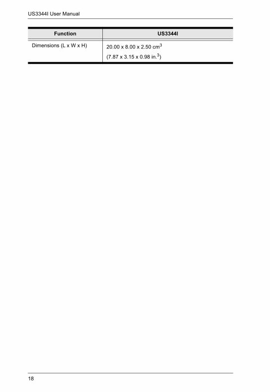
Dimensions (L x W x H) 20.00 x 8.00 x 2.50 cm3
(7.87 x 3.15 x 0.98 in.3)
Function US3344I
Appendix
19
Limited WarrantyATEN warrants its hardware in the country of purchase against flaws in materials and workmanship for a Warranty Period of two [2] years (warranty period may vary in certain regions/countries) commencing on the date of original purchase. This warranty period includes the LCD panel of ATEN LCD KVM switches. Select products are warranted for an additional year (see A+ Warranty for further details). Cables and accessories are not covered by the Standard Warranty.
What is covered by the Limited Hardware WarrantyATEN will provide a repair service, without charge, during the Warranty Period. If a product is detective, ATEN will, at its discretion, have the option to (1) repair said product with new or repaired components, or (2) replace the entire product with an identical product or with a similar product which fulfills the same function as the defective product. Replaced products assume the warranty of the original product for the remaining period or a period of 90 days, whichever is longer. When the products or components are replaced, the replacing articles shall become customer property and the replaced articles shall become the property of ATEN.
To learn more about our warranty policies, please visit our website:http://www.aten.com/global/en/legal/policies/warranty-policy/
© Copyright 2021 ATEN® International Co., Ltd.Released: 2021-05-31
ATEN and the ATEN logo are registered trademarks of ATEN International Co., Ltd. All rights reserved. All other brand names and trademarks are the registered property of their respective owners.