U.S. Traffic Model 222 Detector Operating Manualpeektraffic.com/portal/sites/default/files/US...
31
Operating Manual Operating Manual U.S. Traffic Model 222 Two Channel Digital Loop Detector Sensor Unit
Transcript of U.S. Traffic Model 222 Detector Operating Manualpeektraffic.com/portal/sites/default/files/US...

Operating ManualOperating Manual
U.S. Traffic Model 222Two Channel Digital Loop Detector Sensor Unit
p/n: 99-532 rev 1author: Jay Oyster

Operating Manual
U.S. Traffic Model 222
Two Channel Digital Loop Detector Sensor Unit
3/26/2009

Manual Assembly: 81-1268 Content: MN078018 Rev 9 Cover Art: 99-532
Copyright © 2009 Peek Traffic Corporation All rights reserved. Information furnished by Peek Traffic is believed to be accurate and reliable, however Peek does not warranty the accuracy, completeness, or fitness for use of any of the information furnished. No license is granted by implication or otherwise under any intellectual property. Peek reserves the right to alter any of the Company's products or published technical data relating thereto at any time without notice. No part of this publication may be reproduced, stored in a retrieval system, or transmitted in any form or via any electronic or mechanical means for any purpose other than the purchaser’s personal use without the expressed, written permission of Peek Traffic Corporation, a Signal Group Company. Peek Traffic Corporation. 2906 Corporate Way Palmetto, FL 34221 U.S.A. Trademarks Peek Traffic, iDC, the IDC logo, U.S. Traffic, USTC, and the U.S. Traffic logo are trademarks or registered trademarks of Peek Traffic Corporation in the USA and other countries. Microsoft and Windows are trademarks or registered trademarks of Microsoft Corporation. Other brands and their products are trademarks or registered trademarks of their respective holders.

U.S. Traffic Model 222 Operating Manual 1
TABLE OF CONTENTS
1 TABLE OF CONTENTS ............................................................................................ 1 2 REVISIONS ............................................................................................................... 2 3 General Description................................................................................................. 3 4 Installation Instructions .......................................................................................... 4 5 Operating Instructions ............................................................................................ 5 6 General Theory of Operation .................................................................................. 9 7 Field Troubleshooting ........................................................................................... 11 8 Shop Maintenance and Repair ............................................................................. 11
8.1 Recommended test equipment................................................................... 11 8.2 Preliminary check ....................................................................................... 11 8.3 Current and voltage check.......................................................................... 12 8.4 Detector self check..................................................................................... 12 8.5 Loop oscillator check.................................................................................. 12 8.6 Output indicators check.............................................................................. 12 8.7 Detector output check................................................................................. 12 8.8 Modifications............................................................................................... 13 8.8.1 Failsafe / failsecure mode selection ........................................................... 13 8.8.2 Minimum timing requirement ...................................................................... 13
9 Parts List ................................................................................................................ 15 10 Specifications ........................................................................................................ 19 11 Schematic............................................................................................................... 23
Table of Contents
2 U.S. Traffic Model 222 Operating Manual
List of Tables
Table 1 – Output transistor conditions .............................................................................................3 Table 2 – Pin assignments...............................................................................................................4 Table 3 – Frequency ........................................................................................................................5 Table 4 – PRESENCE or PULSE ....................................................................................................6 Table 5 – Sensitivity .........................................................................................................................6 Table 6 – Disable .............................................................................................................................7 Table 7 – Field troubleshooting......................................................................................................11 Table 8 – Test point descriptions ...................................................................................................12 Table 9 – Eight selectable sensitivity settings................................................................................20 Table 10 – Response Time............................................................................................................20
List of Figures
Figure 1 – 222 Detector front panel (handle shown removed for clarity) ........................................5 Figure 2 – Winky-Blink* ...................................................................................................................7 Figure 3 – Model 222 Block diagram.............................................................................................10 Figure 4 – Board Pictorial ..............................................................................................................14
REVISIONS
Rev By Date Reason 9 Jay Oyster 3/26/09 Reformatted to Peek Standard. Update contact info and
branding. 8 Mark Leatt 11/11/02 Re-formatted to new USTC Standard format

U.S. Traffic Model 222 Operating Manual 3
GENERAL DESCRIPTION
The U.S. Traffic Corporation Model 222 Two Channel Digital Loop Detector Sensor Unit conforms to Caltrans Traffic Control Equipment Specifications dated January 1989 and addendums
This manual is designed to cover the installation, operation and repair of the IDC Detector Systems 222 Two Channel Digital Loop Detector, designed to be installed in an appropriate IDC Detector Systems DS-200 series (or equivalent) Card Rack. These units utilize an advanced digital microprocessor design providing a number of features that enable them to be used in even the most demanding installations. Each loop is sequentially scanned to minimize crosstalk and reduce power consumption. Each loop circuit is continuously monitored to detect intermittents and other faults, and each channel is completely self-tuning. These units have two solid-state outputs. For output conditions for each channel, see Table 1. Note that these units are delivered from the factory in the failsafe mode. In the failsafe mode, a CALL output is provided in the event of a loop failure. In the failsecure mode, the detector does not provide a CALL output in the event of a loop failure. To convert from failsafe mode, refer to Section 8.8.1.
Each channel features front panel capability for selection of four loop frequencies, sensitivity levels, and operating modes (Presence or Pulse). Switching is accomplished by dip switches. All adjustments and controls are separate and independent for each channel, with the exception of the reset input. These features provide optimum utilization when interfacing with an intersection controller. In addition, an on-board jumper for each channel is provided to assure a minimum presence output of 100 milliseconds. To eliminate this minimum timing requirement refer to Section 8.8.2.
Winky-Blink™, a built-in diagnostic feature, provides a fast, easy, and effective method of checking and troubleshooting the detector and the associated traffic control system. This feature is displayed by visual indication (see Figure 2) on the front panel. These units are designed to meet all applicable CALTRANS TRAFFIC SIGNAL CONTROL EQUIPMENT SPECIFICATIONS, NEMA specs and the California/New York 20 Joules lighting test.
Table 1 – Output transistor conditions FAILSECURE FAILSAFE
Detector Power OK Detector Power OK
Normal Loop Failed Normal Loop Failed Output Car No Car Car No Car
Detector Power Out Car No Car Car No Car
Detector Power Out
Presence On Off Off Off Off On Off On On Off Pulse Mom. On Off Off Off Off Mom. On Off On On Off

General Description
4 U.S. Traffic Model 222 Operating Manual
Installation Instructions The unit is wired per Table 2. Carefully install the unit in the appropriate slot in the card file and apply power.
Table 2 – Pin assignments Pin Function Pin Function Pin Function A Power / Logic Common H Output, Ch. 1 (-) S Spare 1 Reserved 8 & J Loop Input, Ch. 2 T Spare B +24VDC Power 9 & K Loop Input, Ch. 2 17 & U Spare 2 Reserved L Spare 18 & V Spare C Reset M Reserved W Output, Ch. 2 (+) 4 & D Loop Input, Ch. 1 N Reserved X Output, Ch. 2 (-) 5 & E Loop Input, Ch. 1 13 & P Spare Y Spare F Output, Ch. 1 (+) 14 & R Spare Z Spare Key slot located between B & C and M & N.
Operating Instructions
U.S. Traffic Model 222 Operating Manual 5
Operating Instructions
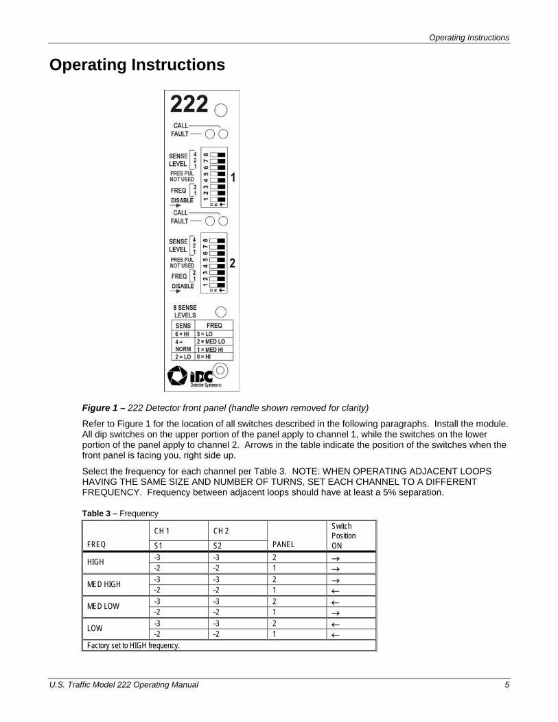
Figure 1 – 222 Detector front panel (handle shown removed for clarity)
Refer to Figure 1 for the location of all switches described in the following paragraphs. Install the module. All dip switches on the upper portion of the panel apply to channel 1, while the switches on the lower portion of the panel apply to channel 2. Arrows in the table indicate the position of the switches when the front panel is facing you, right side up.
Select the frequency for each channel per Table 3. NOTE: WHEN OPERATING ADJACENT LOOPS HAVING THE SAME SIZE AND NUMBER OF TURNS, SET EACH CHANNEL TO A DIFFERENT FREQUENCY. Frequency between adjacent loops should have at least a 5% separation.
Table 3 – Frequency
CH 1 CH 2 Switch Position
FREQ S1 S2 PANEL ON -3 -3 2 → HIGH -2 -2 1 → -3 -3 2 → MED HIGH -2 -2 1 ← -3 -3 2 ← MED LOW -2 -2 1 → -3 -3 2 ← LOW -2 -2 1 ←
Factory set to HIGH frequency.

General Description
6 U.S. Traffic Model 222 Operating Manual
Select either PRES (PRESENCE) or PUL (PULSE) operation for each channel per Table 4.
Table 4 – PRESENCE or PULSE
CH 1 CH 2 Switch Position
MODE S1 S2 ON USE PRES -5 -5 ← For free flow traffic applications PUL -5 -5 → For counting
Factory set to PRES.
Select the proper sensitivity level setting for each channel per Table 5. NOTE: WHEN MULTIPLE LOOPS ARE CONNECTED TOGETHER, THE SERIES CONNECTION PROVIDES THE MOST EFFICIENT AND STABLE OPERATION.
Table 5 – Sensitivity
S1 S2 Switch Position SENS
LEVEL CH1 CH2 ON PANEL
-8 -8 ← 4 -7 -7 ← 2 7 -6 -6 ← 1
Loop areas greater than 100 ft2 and motorcycle detection required.
-8 -8 ← 4 -7 -7 ← 2 6 -6 -6 → 1
HIGH – Commonly used for four six foot by six foot loops connected in series.
-8 -8 ← 4 -7 -7 → 2 5 -6 -6 ← 1
Loop areas of 50 ft2 or less and motorcycle detection required.
-8 -8 ← 4 -7 -7 → 2 4 -6 -6 → 1
NORMAL – Commonly used for a single six foot by six foot loop. Detects automobiles on all size loops up to 600 ft2.
-8 -8 → 4 -7 -7 ← 2 3 -6 -6 ← 1
-8 -8 → 4 -7 -7 ← 2 2 -6 -6 → 1
LOW – Use for narrow lanes. Also used for occupancy and velocity measurements
-8 -8 → 4 -7 -7 → 2 1 -6 -6 ← 1
-8 -8 → 4 -7 -7 → 2 0 -6 -6 → 1
Factory set to level 4.
Move the DISABLE switch for each channel to ON (in the direction opposing the DISABLE identifier arrow) to enable (turn) the channel. (See Table 6) To reset a channel, move the DISABLE switch to OFF (in the direction of the DISABLE identifier arrow) and then back to ON (in the direction opposing the DISABLE identifier arrow). Note that the detector channel is disable and reset when the switch is in the OFF position.

Operating Instructions
U.S. Traffic Model 222 Operating Manual 7
Table 6 – Disable
CH 1 CH 2 Switch Position
Panel S1 S2 ON USE DISABLE -1 -1 → Channel disabled and reset DISABLE -1 -1 ← Channel enabled
Factory set to enabled.
Each channel has a front panel CALL indicator will be illuminated for vehicle detect and extinguished for no detect. It will also be continuously illuminated during an existing out-of-tolerance (failed) loop condition.
Each channel has a front panel Fault indicator. This indicator is continuously illuminated during an existing out-of-tolerance (failed) loop condition and displays a repetitive series of 3 short flashes every second (Winky-Blink™) when the loop fault “self-heals” or is otherwise cleared (see Figure 2). A fail indication may occur following a loop frequency switch position change. If this happens, reset the detector immediately.
Both channels of the detector may be manually reset by removing power momentarily. An individual channel may be manually reset by momentarily changing the sensitivity setting, by momentarily changing the PRES/PULSE switch, or by momentarily moving the disable switch to OFF and back to ON.
Figure 2 – Winky-Blink*
* Winky-Blink™ is a registered trademark of Display Technologies, Inc.
1 SEC
= INDICATOR ON
= INDICATOR OFF
(3 PULSES/SEC) FAIL

General Description
8 U.S. Traffic Model 222 Operating Manual

U.S. Traffic Model 222 Operating Manual 9
GENERAL THEORY OF OPERATION
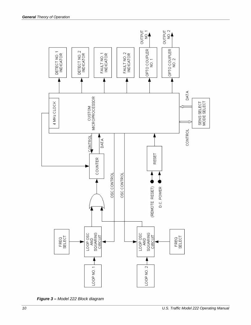
The following discussion applies equally to each channel, unless otherwise noted. Refer to Block Diagram (Figure 3 on page 10.)
The IDC Detector Systems 222 Two Channel Digital Loop Detector operates on the principle of digitally measuring changes in the resonant frequency of the loop network. This is accomplished by providing an excitation voltage to the loop and then continuously monitoring for frequency changes. The loop excitation voltage is coupled to the loop through an isolation transformer. The purpose of the loop isolation transformer is to provide high common mode isolation between the loop and the detector circuitry, which allows the detector to operate with poor quality loops. In addition, the isolation transformer limits the amount of energy coupled into the detector as a result of a static discharge (lighting) near the loop.
As can be seen in the schematic, two suppression devices are used in addition to the transformer. The first device is a neon bulb, which is connected directly across the loop side of the transformer and the second device is a transient suppression device, connected directly across the detector side of the transformer. This transient suppression device clamps the voltage to a safe level to prevent damage to the detector components (i.e. the capacitors and integrated circuits). Also connected across the detector side of the transformer are two capacitors and a switch to permit shifting the frequency of the loop input circuit. This allows frequency separation to be maintained on similar adjacent loops.
The sine wave output of the transformer is then converted into a square wave that is used for digital sampling. The microprocessor sequentially scans (turns on and off) each channel, successively sampling the loop frequency of each channel. Using the ratioed period shift method the microprocessor makes decisions on whether or not to generate a call signal. The call signal output action is a function of the sensitivity control lines, the mode control lines, and the loop frequency. Each channel has completely separate and independent sensitivity, mode and loop frequency controls. Each channel can be individually inhibited (turned off) by moving it’s respective DISABLE switch in the direction of the arrow on the panel. When the external reset line (pin C) is connected to D.C. common (pin A), both detector channels will be reset. Each call signal output line is an optically-coupled transistor.
The detector includes a Winky-Blink™ diagnostic feature that continuously monitors the loop for faulty conditions. If the loop ever experiences an open circuit, the FAULT indicator illuminates continuously while the fault is occurring and then flashes three blinks per second when the loop “self-heals” or is cleared. The output generates a continuous call while the fault is occurring. Once the detector is tuned and in normal operation, the microprocessor sequentially monitors the inductance value change on each loop. If the inductance value quickly changes by 25 percent or more, the detector will go into the fail mode. If the loop heals, the detector will return to normal operation. However, the FAULT indicator will continue to indicate the failure until the detector is reset.
General Theory of Operation
10 U.S. Traffic Model 222 Operating Manual
Figure 3 – Model 222 Block diagram

Field Troubleshooting
U.S. Traffic Model 222 Operating Manual 11
Field Troubleshooting If the detector does not operate properly after the initial installation, use the following procedures to locate the fault. Note that each of these points was covered in the installation and operating instructions.
Table 7 – Field troubleshooting
SYMPTON POSSIBLE CAUSE CORRECTION Detector does not operate (both channels).
1. No 24 VDC 2. Remote reset line is grounded
1. Repair or replace power supply. (Voltage must be + 16 to +30 VDC.)
2. Remove ground from reset line (pin C).
One detector output and indicator are off.
Channel disabled. Reset DISABLE switch to the left (ON).
Fault indicator flashed in groups of 3 short flashes per second.
1. Faulty or open loop or lead-in. 2. Loose connections and/or poorly
crimped terminals. 3. Defective external suppression
(lightning protection) device connected across the loop.
1. Perform D.C. resistance test of loop (normally < 5 ohms).
2. Perform megger test between loop lead and ground (≥ 100 megaohms).
3. Check that loop lead-in is tightly connected to the proper terminals and that the terminal crimp sleeves are soldered.
4. Check that splices are tightly soldered and sealed against moisture.
5. Remove external device (not required with IDC Detector Systems unit).
Insufficient sensitivity to detect motorcycles. (Multiple loops.)
1. Loops not connected in series. 2. Improper sensitivity setting.
1. Connect loops in series. 2. Increase sensitivity slightly.
Shop Maintenance and Repair No routine maintenance or adjustment of the sensor unit is required.
Recommended test equipment The following pieces of test equipment are recommended for use in the troubleshooting and repair of the IDC Detector Systems 222 Two Channel Digital Loop Detector. This does not exclude the use of equivalent locally procured or constructed test equipment.
Dual Trace Oscilloscope, 50 MHz minimum bandwidth.
Digital Multimeter.
Preliminary check Connect the detector to either a normal loop or a bench test loop with approximately 100 microhenries of inductance. Referring to the Operating Instructions (Section 5) select high frequency, presence mode, sensitivity level 4 and ensure that the disable switch for each channel is in the ON position to turn on the channels. Connect one side of all the test instrument inputs to signal common.
Refer to Figure 4 (Board Pictorial, Section 8) and Table 8 for test point locations and nominal signal levels.
General Theory of Operation
12 U.S. Traffic Model 222 Operating Manual
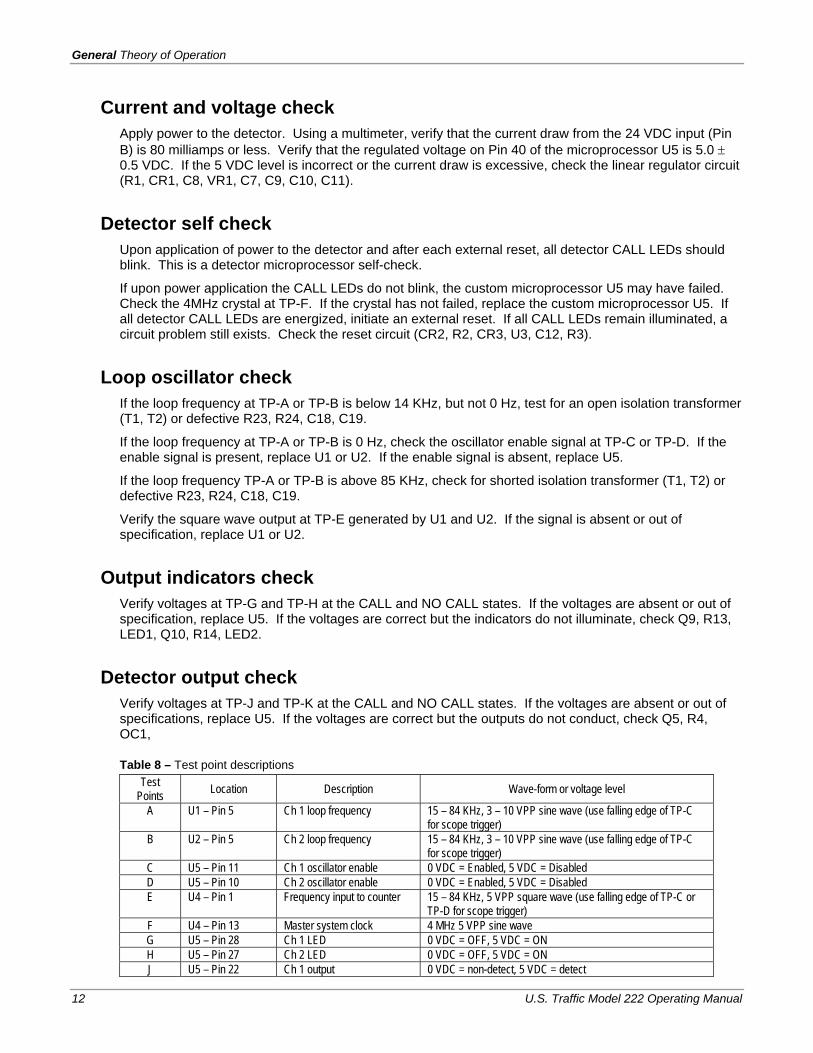
Current and voltage check Apply power to the detector. Using a multimeter, verify that the current draw from the 24 VDC input (Pin B) is 80 milliamps or less. Verify that the regulated voltage on Pin 40 of the microprocessor U5 is 5.0 ± 0.5 VDC. If the 5 VDC level is incorrect or the current draw is excessive, check the linear regulator circuit (R1, CR1, C8, VR1, C7, C9, C10, C11).
Detector self check Upon application of power to the detector and after each external reset, all detector CALL LEDs should blink. This is a detector microprocessor self-check.
If upon power application the CALL LEDs do not blink, the custom microprocessor U5 may have failed. Check the 4MHz crystal at TP-F. If the crystal has not failed, replace the custom microprocessor U5. If all detector CALL LEDs are energized, initiate an external reset. If all CALL LEDs remain illuminated, a circuit problem still exists. Check the reset circuit (CR2, R2, CR3, U3, C12, R3).
Loop oscillator check If the loop frequency at TP-A or TP-B is below 14 KHz, but not 0 Hz, test for an open isolation transformer (T1, T2) or defective R23, R24, C18, C19.
If the loop frequency at TP-A or TP-B is 0 Hz, check the oscillator enable signal at TP-C or TP-D. If the enable signal is present, replace U1 or U2. If the enable signal is absent, replace U5.
If the loop frequency TP-A or TP-B is above 85 KHz, check for shorted isolation transformer (T1, T2) or defective R23, R24, C18, C19.
Verify the square wave output at TP-E generated by U1 and U2. If the signal is absent or out of specification, replace U1 or U2.
Output indicators check Verify voltages at TP-G and TP-H at the CALL and NO CALL states. If the voltages are absent or out of specification, replace U5. If the voltages are correct but the indicators do not illuminate, check Q9, R13, LED1, Q10, R14, LED2.
Detector output check Verify voltages at TP-J and TP-K at the CALL and NO CALL states. If the voltages are absent or out of specifications, replace U5. If the voltages are correct but the outputs do not conduct, check Q5, R4, OC1,
Table 8 – Test point descriptions Test
Points Location Description Wave-form or voltage level
A U1 – Pin 5 Ch 1 loop frequency 15 – 84 KHz, 3 – 10 VPP sine wave (use falling edge of TP-C for scope trigger)
B U2 – Pin 5 Ch 2 loop frequency 15 – 84 KHz, 3 – 10 VPP sine wave (use falling edge of TP-C for scope trigger)
C U5 – Pin 11 Ch 1 oscillator enable 0 VDC = Enabled, 5 VDC = Disabled D U5 – Pin 10 Ch 2 oscillator enable 0 VDC = Enabled, 5 VDC = Disabled E U4 – Pin 1 Frequency input to counter 15 – 84 KHz, 5 VPP square wave (use falling edge of TP-C or
TP-D for scope trigger) F U4 – Pin 13 Master system clock 4 MHz 5 VPP sine wave G U5 – Pin 28 Ch 1 LED 0 VDC = OFF, 5 VDC = ON H U5 – Pin 27 Ch 2 LED 0 VDC = OFF, 5 VDC = ON J U5 – Pin 22 Ch 1 output 0 VDC = non-detect, 5 VDC = detect

Modifications
U.S. Traffic Model 222 Operating Manual 13
K U5 – Pin 21 Ch 2 output 0 VDC = non-detect, 5 VDC = detect
Modifications The IDC Detector Systems 222 Two Channel Digital Loop Detector may be modified to select a minimum presence output timing requirement. Before making this modification, remove the +24 VDC power from the detector sensor unit.
Failsafe / failsecure mode selection The IDC Detector Systems 222 Two Channel Digital Loop Detector is shipped in the failsafe mode. To convert to the failsecure mode, install diode CR45. The location is shown in the Board Pictorial, Figure 4.
Minimum timing requirement The IDC Detector Systems 222 Two Channel Digital Loop Detector is shipped with minimum presence output timing of 100 milliseconds. To eliminate this minimum timing requirement, remove JMP1 for channel 1 and JMP2 for channel 2. The location is shown in the Board Pictorial, Figure 4.

General Theory of Operation
14 U.S. Traffic Model 222 Operating Manual
Figure 4 – Board Pictorial
U.S. Traffic Model 222 Operating Manual 15
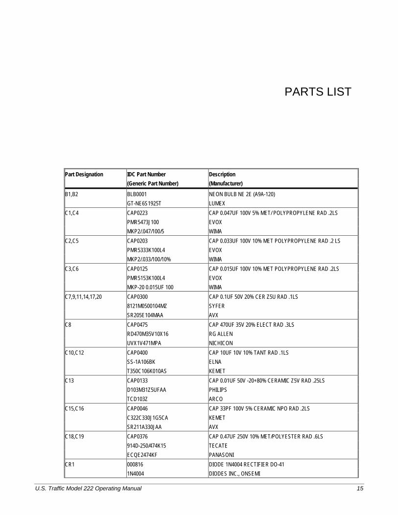
PARTS LIST
Part Designation IDC Part Number Description (Generic Part Number) (Manufacturer)
B1,B2 BLB0001 NEON BULB NE 2E (A9A-120) GT-NE6S1925T LUMEX C1,C4 CAP0223 CAP 0.047UF 100V 5% MET/ POLYPROPYLENE RAD .2LS PMR5473J100 EVOX MKP2/.047/100/5 WIMA C2,C5 CAP0203 CAP 0.033UF 100V 10% MET POLYPROPYLENE RAD .2 LS PMR5333K100L4 EVOX MKP2/.033/100/10% WIMA C3,C6 CAP0125 CAP 0.015UF 100V 10% MET POLYPROPYLENE RAD .2LS PMR5153K100L4 EVOX MKP-20 0.015UF 100 WIMA C7,9,11,14,17,20 CAP0300 CAP 0.1UF 50V 20% CER Z5U RAD .1LS 8121M0500104MZ SYFER SR205E104MAA AVX C8 CAP0475 CAP 470UF 35V 20% ELECT RAD .3LS RD470M35V10X16 RG ALLEN UVX1V471MPA NICHICON C10,C12 CAP0400 CAP 10UF 10V 10% TANT RAD .1LS SS-1A106BK ELNA T350C106K010AS KEMET C13 CAP0133 CAP 0.01UF 50V -20+80% CERAMIC Z5V RAD .25LS D103M31Z5UFAA PHILIPS TCD103Z ARCO C15,C16 CAP0046 CAP 33PF 100V 5% CERAMIC NPO RAD .2LS C322C330J1G5CA KEMET SR211A330JAA AVX C18,C19 CAP0376 CAP 0.47UF 250V 10% MET/POLYESTER RAD .6LS 914D-250/474K15 TECATE ECQE2474KF PANASONI CR1 000816 DIODE 1N4004 RECTIFIER DO-41 1N4004 DIODES INC., ONSEMI
Parts List
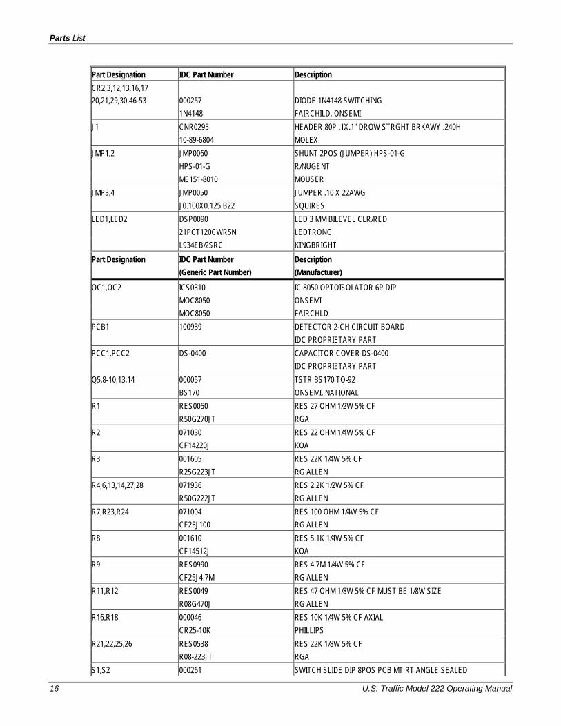
16 U.S. Traffic Model 222 Operating Manual
Part Designation IDC Part Number Description CR2,3,12,13,16,17 20,21,29,30,46-53 000257 DIODE 1N4148 SWITCHING 1N4148 FAIRCHILD, ONSEMI J1 CNR0295 HEADER 80P .1X.1" DROW STRGHT BRKAWY .240H 10-89-6804 MOLEX JMP1,2 JMP0060 SHUNT 2POS (JUMPER) HPS-01-G HPS-01-G R/NUGENT ME151-8010 MOUSER JMP3,4 JMP0050 JUMPER .10 X 22AWG J0.100X0.125 B22 SQUIRES LED1,LED2 DSP0090 LED 3 MM BILEVEL CLR/RED 21PCT120CWR5N LEDTRONC L934EB/2SRC KINGBRIGHT Part Designation IDC Part Number Description (Generic Part Number) (Manufacturer)
OC1,OC2 ICS0310 IC 8050 OPTOISOLATOR 6P DIP MOC8050 ONSEMI MOC8050 FAIRCHLD PCB1 100939 DETECTOR 2-CH CIRCUIT BOARD IDC PROPRIETARY PART PCC1,PCC2 DS-0400 CAPACITOR COVER DS-0400 IDC PROPRIETARY PART Q5,8-10,13,14 000057 TSTR BS170 TO-92 BS170 ONSEMI, NATIONAL R1 RES0050 RES 27 OHM 1/2W 5% CF R50G270JT RGA R2 071030 RES 22 OHM 1/4W 5% CF CF14220J KOA R3 001605 RES 22K 1/4W 5% CF R25G223JT RG ALLEN R4,6,13,14,27,28 071936 RES 2.2K 1/2W 5% CF R50G222JT RG ALLEN R7,R23,R24 071004 RES 100 OHM 1/4W 5% CF CF25J100 RG ALLEN R8 001610 RES 5.1K 1/4W 5% CF CF14512J KOA R9 RES0990 RES 4.7M 1/4W 5% CF CF25J4.7M RG ALLEN R11,R12 RES0049 RES 47 OHM 1/8W 5% CF MUST BE 1/8W SIZE R08G470J RG ALLEN R16,R18 000046 RES 10K 1/4W 5% CF AXIAL CR25-10K PHILLIPS R21,22,25,26 RES0538 RES 22K 1/8W 5% CF R08-223JT RGA S1,S2 000261 SWITCH SLIDE DIP 8POS PCB MT RT ANGLE SEALED

Modifications
U.S. Traffic Model 222 Operating Manual 17
Part Designation IDC Part Number Description DA08T APEM DA-08T TAIWAY SIP1 RES1055 RESNET 22K 2% SIP10 BUSS 4610X-101-223 BOURNS SIP2 RES1053 RESNET 22K 2% SIP6 BUSSED 4606X-101-223 BOURNS SKT1 000852 SOCKET IC 40P DIP *WITH* CENTER SUPPORT,STAMPED AUGAT 340-AG19DC R-NUGENT ICO-406-S8A-T T1,T2 DS-0824 LOOP ISOLATION XFMR (RED-RED) IDC PROPRIETARY PART TP1 SKT0042 SOCKET 4P SIP 10" GOLD 510-AG91D-04ES AUGAT SBE-040-S-TG R-NUGENT U1,U2 101222 BOM-PCB LOOP OSC V4.0 SMT IDC PROPRIETARY PART
Part Designation IDC Part Number Description (Generic Part Number) (Manufacturer)
U3 ICS0566 IC 34164P-5 UNDERVOLTAGE SENSE TO-92 MC34164P-5 MOTOROLA U4 ICS0505-99 IC DS0505 ASIC COUNTER 1999 VERSION IDC PROPRIETARY PART U5 DS93242B BOM-68HC05C8 W/D93242B MICROPROCESSOR IDC PROPRIETARY PART VR1 000239 IC LM7805 REGULATOR +5V L7805CV SGS MC7805CT MOTOROLA X1 XTL0050 CRYSTAL 4 MHZ HC-18 SRMP49-4.000 PELTRONI 4.00 MHZ RALTRON Z1,Z2 DIO0130 DIODE P6KE6.8CA TRANSIENT SUPPRESSOR P6KE6.8CA ON SEMI, GEN SEMI Z7,Z8 DIO0140 DIODE P6KE36A TRANSIENT SUPPRESSOR P6KE36A ON SEMI, GEN SEMI

Parts List
18 U.S. Traffic Model 222 Operating Manual
U.S. Traffic Model 222 Operating Manual 19
SPECIFICATIONS
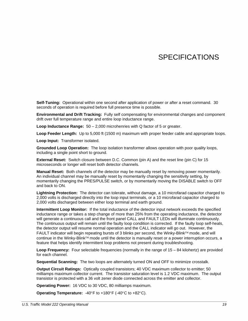
Self-Tuning: Operational within one second after application of power or after a reset command. 30 seconds of operation is required before full presence time is possible.
Environmental and Drift Tracking: Fully self compensating for environmental changes and component drift over full temperature range and entire loop inductance range.
Loop Inductance Range: 50 – 2,000 microhenries with Q factor of 5 or greater.
Loop Feeder Length: Up to 5,000 ft (1500 m) maximum with proper feeder cable and appropriate loops.
Loop Input: Transformer isolated.
Grounded Loop Operation: The loop isolation transformer allows operation with poor quality loops, including a single point short to ground.
External Reset: Switch closure between D.C. Common (pin A) and the reset line (pin C) for 15 microseconds or longer will reset both detector channels.
Manual Reset: Both channels of the detector may be manually reset by removing power momentarily. An individual channel may be manually reset by momentarily changing the sensitivity setting, by momentarily changing the PRES/PULSE switch, or by momentarily moving the DISABLE switch to OFF and back to ON.
Lightning Protection: The detector can tolerate, without damage, a 10 microfarad capacitor charged to 2,000 volts is discharged directly into the loop input terminals, or a 10 microfarad capacitor charged to 2,000 volts discharged between either loop terminal and earth ground.
Intermittent Loop Monitor: If the total inductance of the detector input network exceeds the specified inductance range or takes a step change of more than 25% from the operating inductance, the detector will generate a continuous call and the front panel CALL and FAULT LEDs will illuminate continuously. The continuous output will remain until the faulty loop condition is corrected. If the faulty loop self-heals, the detector output will resume normal operation and the CALL indicator will go out. However, the FAULT indicator will begin repeating bursts of 3 blinks per second, the Winky-Blink™ mode, and will continue in the Winky-Blink™ mode until the detector is manually reset or a power interruption occurs, a feature that helps identify intermittent loop problems not present during troubleshooting.
Loop Frequency: Four selectable frequencies (normally in the range of 15 – 84 kilohertz) are provided for each channel.
Sequential Scanning: The two loops are alternately turned ON and OFF to minimize crosstalk.
Output Circuit Ratings: Optically coupled transistors; 40 VDC maximum collector to emitter; 50 milliamps maximum collector current. The transistor saturation level is 1.2 VDC maximum. The output transistor is protected with a 36 volt zener diode connected across the emitter and collector.
Operating Power: 16 VDC to 30 VDC, 80 milliamps maximum.
Operating Temperature: -40°F to +180°F (-40°C to +82°C).

Specifications
20 U.S. Traffic Model 222 Operating Manual
Connector: 2 x 22-pin edge card connector with 0.156 inch contact centers. Key slots are located between B and C, M and N.
Size: 4.500 inches (11.5 cm) high by 6.875 inches (17.5 cm) long by 1.12 inches (2.8 cm) wide. Edge card connector is centered on the 4.500 inch (11.5 cm) edge.
Weight: 6 oz (170 g)
Channel Off State: When the front panel DISABLE DIP switch is set to OFF, the output is off and the channel is disabled and reset.
Detect Indicator Operation: High intensity red light emitting diode (LED) indicates output status of each detector channel.
CALL OUTPUT: Steady on while vehicle is being detected.
FAILED or OUT-OF-RANGE LOOP CONDITION: Steady on as long as fault exists.
Fault Indicator Operation: High intensity red light emitting diode (LED) indicates fault status of the loop for each detector channel.
EXISTING FAULT CONDITION: On steady
PAST FAULT CONDITION: Indicator emits the Winky-Blink™ signal of three 50 ms blinks, 50 ms apart, which repeats once per second until reset. (NOTE: If loop frequency is manually changed, the fail indication may appear, if the detector is not reset.)
Sensitivity Sensitivity: Vehicle detection results from a sufficient negative change in loop inductance
(-ΔL/L). Note that the detector channel is reset automatically whenever the sensitivity level is changed.
Table 9 – Eight selectable sensitivity settings
Sensitivity -ΔL/L Sensitivity -ΔL/L Level 7 0.01% Level 3 0.16% Level 6 0.02% Level 2 0.32% Level 5 0.04% Level 1 0.64% Level 4 0.08% Level 0 1.28%
Response Time Table 10 – Response Time
Response Time Response Time Sensitivity Min. Max.
Sensitivity Min. Max.
Level 0 1.4 ms 3.4 ms Level 4 1.4 ms 5 ms Level 1 1.4 ms 3.4 ms Level 5 2 ms 9 ms Level 2 1.4 ms 3.4 ms Level 6 5 ms 18.5 ms Level 3 1.4 ms 3.5 ms Level 7 9 ms 32.5 ms
Modes PRES (Long): Presence mode with a hold time of 4 minutes minimum (regardless of vehicle size) and typically 60 to 90 minutes for a car.
PULSE: In the pulse mode, each vehicle generates a pulse output of 125 ± 25 milliseconds. Should a vehicle remain over the loop for 2 seconds or longer, the detector will tune out the vehicle such that the

Modes
U.S. Traffic Model 222 Operating Manual 21
remainder of the loop zone detects subsequent vehicles after 2 seconds. When the vehicle leaves the loop, the detector resumes full sensitivity within 0.75 seconds.
Note Specifications are subject to change to reflect improvements and upgrades.
Note:
Specifications meet or exceed CALTRANS TRAFFIC SIGNAL
CONTROL EQUIPMENT SPECIFICATIONS, dated January 1989 and the TSCES Chapter 5 Addendum, dated July 1991
and all NEMA Standards.

Specifications
22 U.S. Traffic Model 222 Operating Manual
U.S. Traffic Model 222 Operating Manual 23
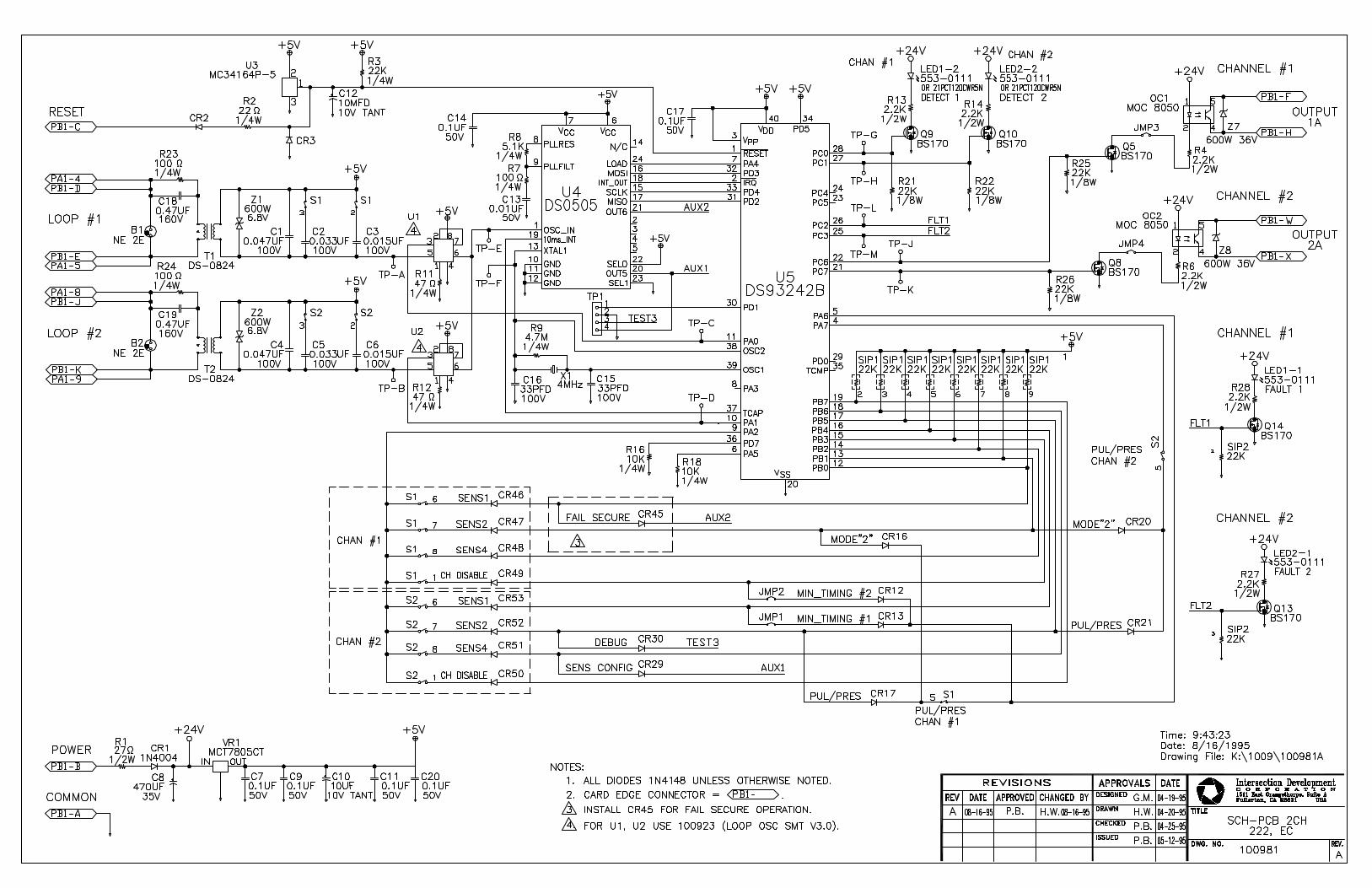
Schematic
The following page contains the schematic for the U.S. Trafffic Model 222 circuit board.

Specifications
24 U.S. Traffic Model 222 Operating Manual


p/n: 81-1268
Peek Traffic Corporation2906 Corporate WayPalmetto, FL 34221ph: (941) 845-1200toll free in U.S.: (800) 245-7660fax: (941) 845-1504email: [email protected]
www.peektraffic.com