u.s. PoL c - NASA · ASRB Heat Flux Input as a Function of Time Schematic of Quartz Lamp Thermal...
288
SLZ-MMZ-92-564-7079 SEB THERMAL CUET_lqq DESIGN SUPPORT NOVEMBER 1992 FINAL REPORT TO u.s. PoL_c B.P. CHEMICALS SANTA ANA, CALIFORNTA 92705 PUP.CHASE ORDER NUlqBER 62550 PEIME CONTRACT NU_BERNAS8-38261 (H&g A_C_-I,_ {_5 :_) SRJ THERMAL _{ei)ort ' _ c_-h. t990 - 2"3 F_'D. 1993 (Southurn t{eseJrch Tnst.) 101 p N94-17124 Uncl as G3/20 0193052 I Southern ?.esearcn ins_itu:e 1 https://ntrs.nasa.gov/search.jsp?R=19940012651 2018-08-13T11:04:55+00:00Z
Transcript of u.s. PoL c - NASA · ASRB Heat Flux Input as a Function of Time Schematic of Quartz Lamp Thermal...
SLZ-MMZ-92-564-7079
SEB THERMAL CUET_lqq DESIGN SUPPORT
NOVEMBER 1992 FINAL REPORT TO
u.s. PoL_cB.P. CHEMICALS
SANTA ANA, CALIFORNTA 92705
PUP.CHASE ORDER NUlqBER 62550
PEIME CONTRACT NU_BERNAS8-38261
(H&g A_C_-I,_ {_5 :_) SRJ THERMAL
_{ei)ort ' _ c_-h. t990 - 2"3 F_'D. 1993(Southurn t{eseJrch Tnst.) 101 p
N94-17124
Uncl as
G3/20 0193052
I Southern ?.esearcn ins_itu:e
1
https://ntrs.nasa.gov/search.jsp?R=19940012651 2018-08-13T11:04:55+00:00Z

4 _ _-D
SRI'MME-92-564-7079
SRB THERMAL CURTAIN DESIGN SUPPORT
November 1992 Final Report
to
U.S. POLYMERIC
B.P. CHEMICALS
Advanced Materials Division
Fibers and Materials
700 East Dyer Road
Santa Ana, Californla 92705
Purchase Order Number 62550
Prime Contract Number NAS8-38261
by
SOUTHERN RESEARCH INSTITUTE
2000 9th Avenue South
P.O. Box 55305
Birmingham, Alabama 35255
Prepared by
Carl A. Dixon //
Assistant Engineer
Applied Thermal Section
Approved by
_ophyslcal Research Department
November 1992

TABLE OF CONTENTS
3.0
INTRODUCTION
THERMOPHYSICAL MEASUREMENTS
2.1 CONCLUSIONS
MODELLING
3.1 COMPUTER PROGRAM
3.2 ANALOG TEST FACILITY
3.3 RESULTS AND CONCLUSIONS
4.0 DESIGN OPTIMIZATION
4.1 COST CONSIDERATIONS
5.0 CONCLUSIONS
REFERENCES
LIST OF APPENDICES
1
6
2O
21
21
28
33
49
54
55
56
57
ii

LIST OF ILLUSTRATIONS
i.i
1.2
1.3
2.1
2.2
2.3
2.4
2.5
2.6
3.1-1
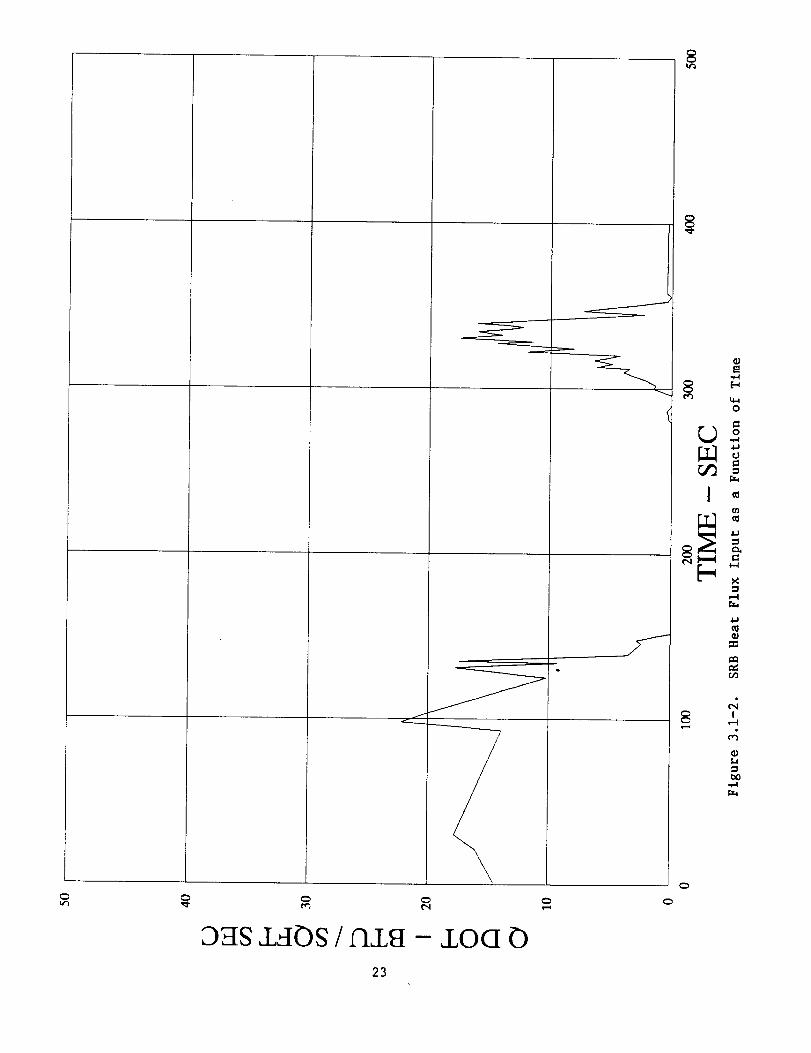
3.1-2
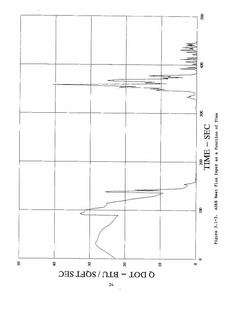
3.1-3
3.2-1
3.2-2
3.2-3
3.2-4
3.3-1
3.3-2
3.3-3
3.3-4
3.3-5
3.3-6
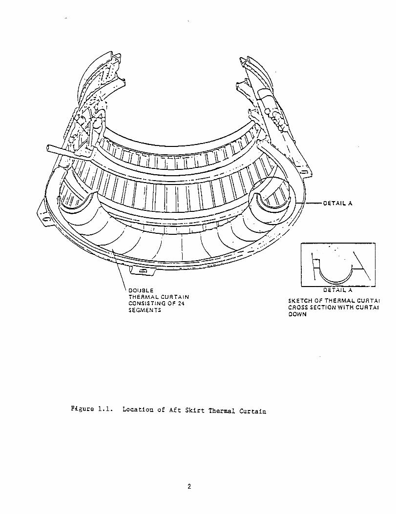
Location of Aft Skirt Thermal Curtain
Aft Skirt Thermal Curtain Construction
Aft Skirt Thermal Curtain Installation
Specific Heat of Quartz Fabric
Specific Heat of S-Glass Fabric
Specific Heat of Kevlar Fabric
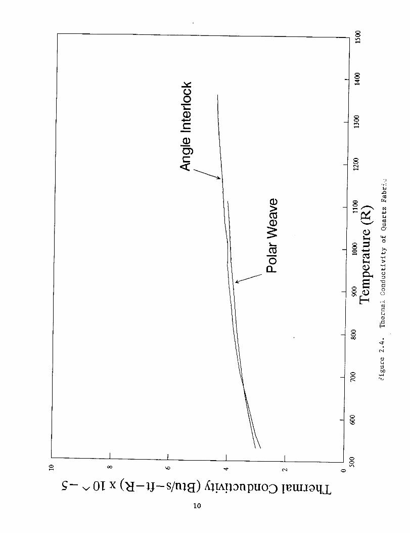
Thermal Conductivity of Quartz Fabric
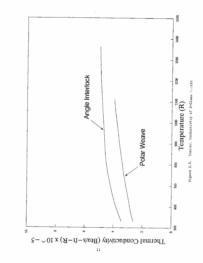
Thermal Conductivity of S-Glass Fabric
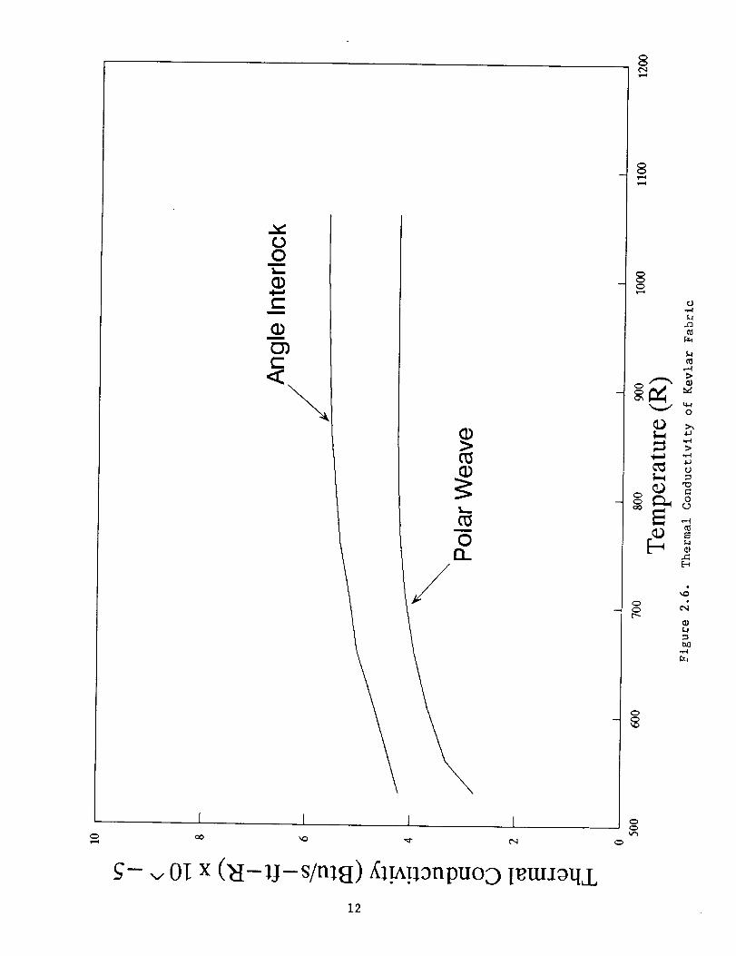
Thermal Conductivity of Kevlar Fabric
Four Node Configuration
SRB Heat Flux Input as a Function of Time
ASRB Heat Flux Input as a Function of Time
Schematic of Quartz Lamp Thermal Flux Facility
NASA/MSFC Analog Test Setup
Incident Heat Flux for NASA Analog Test
Vacuum Pressure versus Time for NASA Analog Test
Analog Test Data for Quartz/S-glass/Kevlar
Configuration Exposed to SRB Flux
Analog Test Data for Quartz/S-glass/Kevlar
Configuration Exposed to ASRB Flux
NASA Analog Test Data for Quartz/S-glass/KevlarConfiguration (Top Specimen)
NASA Analog Test Data for Quartz/S-glass/Kevlar
Configuration (Top Specimen)
NASA Analog Test Data for Quartz/S-glass/KevlarConfiguration (Bottom Specimen)
NASA Analog Test Data for Quartz/S-glass/Kevlar
Configuration (Bottom Specimen)
Pa_ m
2
3
4
7
8
9
i0
Ii
12
22
23
24
29
30
31
32
35
36
37
38
39
40
iii

LIST OF ILLUSTRATIONS (Continued)
3.3-8
3.3-9
3.3-10
3.3-11
3.3-12
3.3-13
3.3-14
4.1
4.2
4.3
4.4
Comparison of SRI and NASA Analog Test Data for Front
Layers of Quartz/S-glass/Kevlar Configuration
Comparison of SRI and NASA Analog Test Data for Rear
Layers of Quartz/S-glass/Kevlar Configuration
Extrapolated Thermal Conductivity of Polar WeaveQuartz
Extrapolated Thermal Conductivity of Polar WeaveS-glass
Thermal Analysis of Quartz/S-glass/Kevlar ConfigurationExposed to SRB Flux
Thermal Analysis of Quartz/S-glass/Kevlar ConfigurationExposed to ASRB Flux
Comparison of Analog Test Data and Thermal Analysis
Predictions for Quartz/S-glass/Kevlar ConfigurationExposed to SRB Flux
Comparison of Analog Test Data and Thermal Analysis
Predictions for Quartz/S-glass/Kevlar ConfigurationExposed to ASRB Flux
Thermal Analysis of Quartz/Kevlar Configuration Exposedto SRB Flux
Thermal Analysis of Quartz/Kevlar Configuration Exposedto ASRB Flux
Analog Test Data for Quartz/Kevlar Configuration Exposedto SRB Flux
Analog Test Data for Quartz/Kevlar Configuration Exposedto ASRB Flux
41
42
43
44
45
46
47
48
50
51
52
53
iv

LIST OF TABLES
Table
i.i
2.1
2.2
2.3
2.4
2.5
2.6
2.7
3.1-i
3.1-2
3.1-3
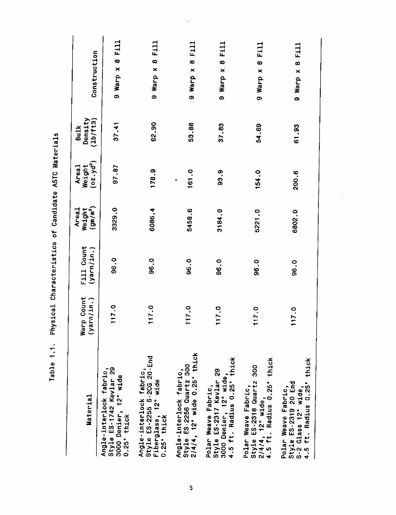
Physical Characteristics of Candidate ASTCMaterials
Recommended Specific Heat of Quartz Fabric
Recommended Specific Heat of S-Glass Fabric
Recommended Specific Heat of Kevlar Fabric
Recommended Thermal Conductivity of Quartz Fabric
Recommended Thermal Conductivity of S-Glass Fabric
Recommended Thermal Conductivity of Kevlar Fabric
Optical Properties Measurements at 530°R
Nodal Equations
Matrix Form of Nodal Equations
Matrix Coefficients
Pa__m
5
13
14
15
16
17
18
19
25
26
27
V

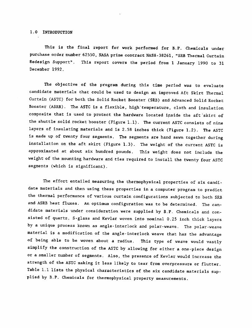
1.0 INTRODUCTION
This is the final report for work performed for B.P. Chemicals under
purchase order number 62550, NASA prime contract NAS8-38261, "SRB Thermal Curtain
Redesign Support". This report covers the period from 1 January 1990 to 31
December 1992.
The objective of the program during this time period was to evaluate
candidate materials that could be used to design an improved Aft Skirt Thermal
Curtain (ASTC) for both the Solid Rocket Booster (SRB) and Advanced Solid Rocket
Booster (ASRB). The ASTC is a flexible, hlgh'temperature, cloth and insulation
composite that is used to protect the hardware located inside the aft'skirt of
the shuttle solid rocket booster (Figure I.I). The current ASTC consists of nine
layers of insulating materials and is 2.58 inches thick (Figure 1.2). The ASTC
is made up of twenty four segments. The segments are hand sewn together during
installation on the aft skirt (Figure 1.3). The weight of the current ASTC is
approximated at about six hundred pounds. This weight does not include the
weight of the mounting hardware and ties required to install the twenty four ASTC
segments (which is significant).
The effort entailed measuring the thermophysical properties of six candi-
date materials and then using these properties in a computer program to predict
the thermal performance of various curtain configurations subjected to both SRB
and ASRB heat fluxes. An optimum configuration was to be determined. The can-
didate materials under consideration were supplied by B.P. Chemicals and con-
sisted of quartz, S-glass and Kevlar woven into nominal 0.25 inch thick layers
by a unique process known as angle-interlock and polar-weave. The polar-weave
material is a modification of the angle-interlock weave that has the advantage
of being able to be woven about a radius. This type of weave would vastly
simplify the construction of the ASTC by allowing for either a one-piece design
or a smaller number of segments. Also, the presence of Kevlar would increase the
strength of the ASTC making it less likely to tear from overpressure or flutter.
Table i.i lists the physical characteristics of the six candidate materials sup-
plied by B.P. Chemicals for thermophysical property measurements.

_OETAIL A
DOUBLETHERMAL CURTAINCONSISTING OF 24SEGMENTS
DETAIL A
_KETCH OF THERMAL CURTAlCROSS SECTION WITH CURTAlgOWN
F{_ure i.i. Location of Aft Skirt Thermal Curtain
2

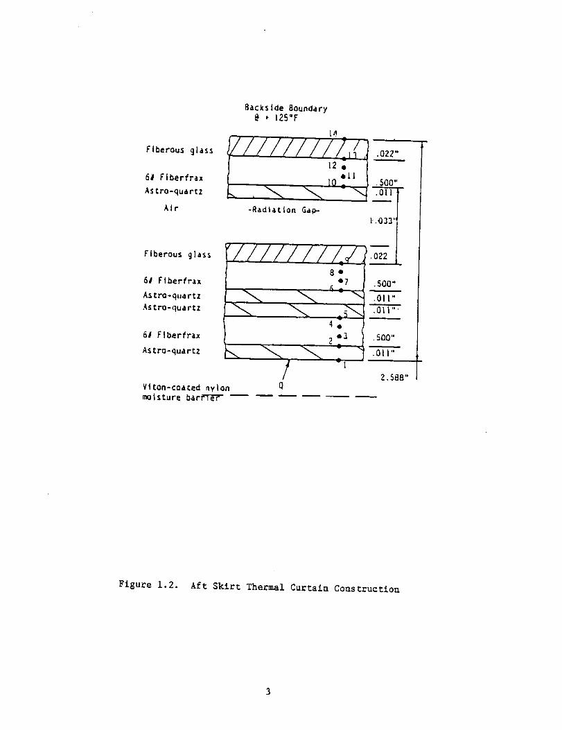
Flberous _lass
6# Flberfrax
As tro-quartz
Atr
Backslde Boundary@ _ 125°F
-Radiation Gap-
|
•022"
• 508"
o-: TF1-.033"
Fiberous glass
6# Flberfrax
Astro-quartz
Astro-quartz
6l Flberfrax
Astro-quartz
Viton-coated nylon Q
.500"
.Oll"
2.588"
moisture bar_'TLrr ......
Figure 1.2. Aft Skirt Thermal Curtain Construction

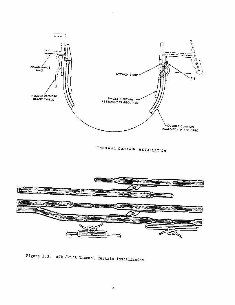
THERMAL CURTAZN INSTALL,_,TtON
Figure 1.3. Aft Skirt Thermal Curtain Installation

g),-gm
-,-IL
4_
=E
(.3I--¢/)<C
"0-H"0C
vr-0
u)U
"HL
U
L
r-
U'H(0
O.
,r-
.O
0.*..I4-,U=L
4.J03c-O
(.3
"_ ",4 4-J
L-_ N
m_- E
Ar-=d0 .,'-I
c-.',--I L,-4 m.,-iIa_ ----
A
-,d0._
t-0.£.
,H(U
._-IL
=E
,.-I ,--I *--I ,-( ,--I ,--I_'1 ,-4 ,-.1 _ ,--I ,--I•,-I "H "_ .,"4 -.-I -..ILI.. 14. 14. 14. LI. 14.
O0 _0 O0 O0 CO CO
X X X X X X
@ @ @ @ @ @O'3 O) O_ (3) O) O)
CO (33 0 0) 0 (O
r,,. oO - _'- _ _ 0O) r,. (o (3) _ o
o ,_ (D 0 o o
CO _') OD OQ 0OD 0 _" _" C_I COO_ QD _ CO _ (0
O O O O O O
r.O ¢O (.ID (ID (ID _IDO_ (3) O') O) O') O)
0 0 0 0 0 0
•- :- 7- = = "-

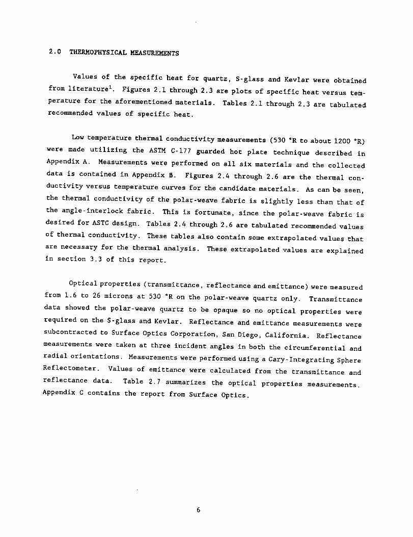
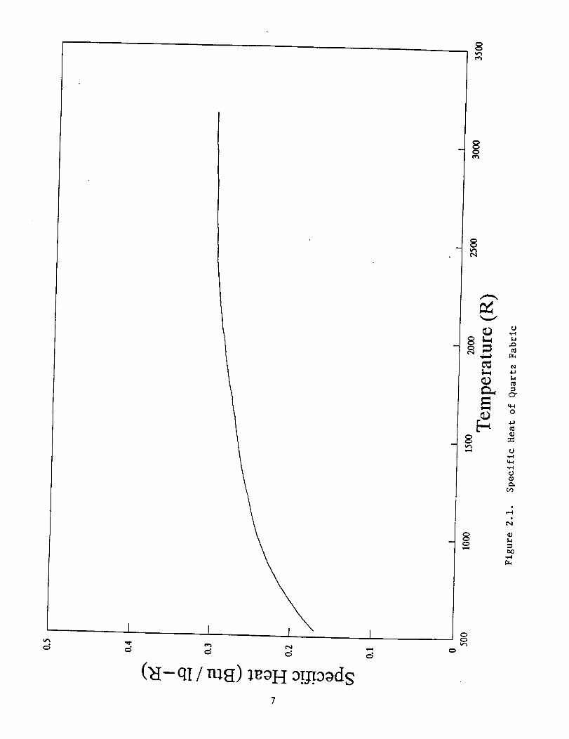
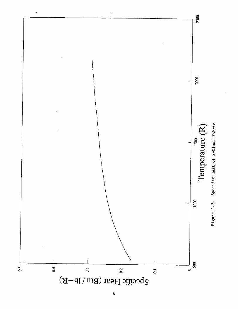
2.0 THERMOPHYSICALMEASUREMENTS
Values of the specific heat for quartz, S-glass and Kevlar were obtained
from literature I. Figures 2.1 through 2.3 are plots of specific heat versus tem-
perature for the aforementioned materials. Tables 2.1 through 2.3 are tabulated
recommended values of specific heat.
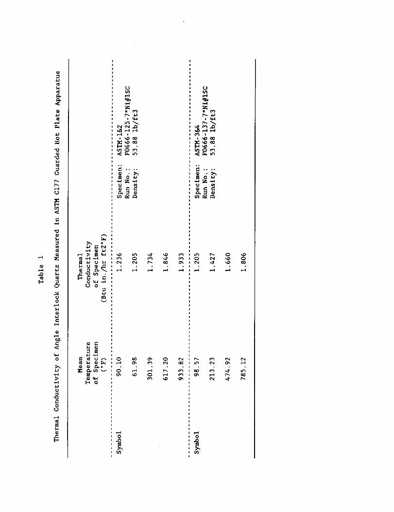
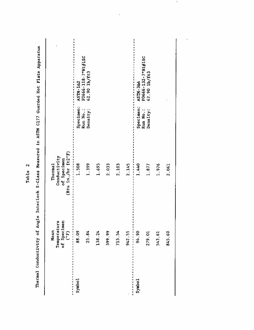
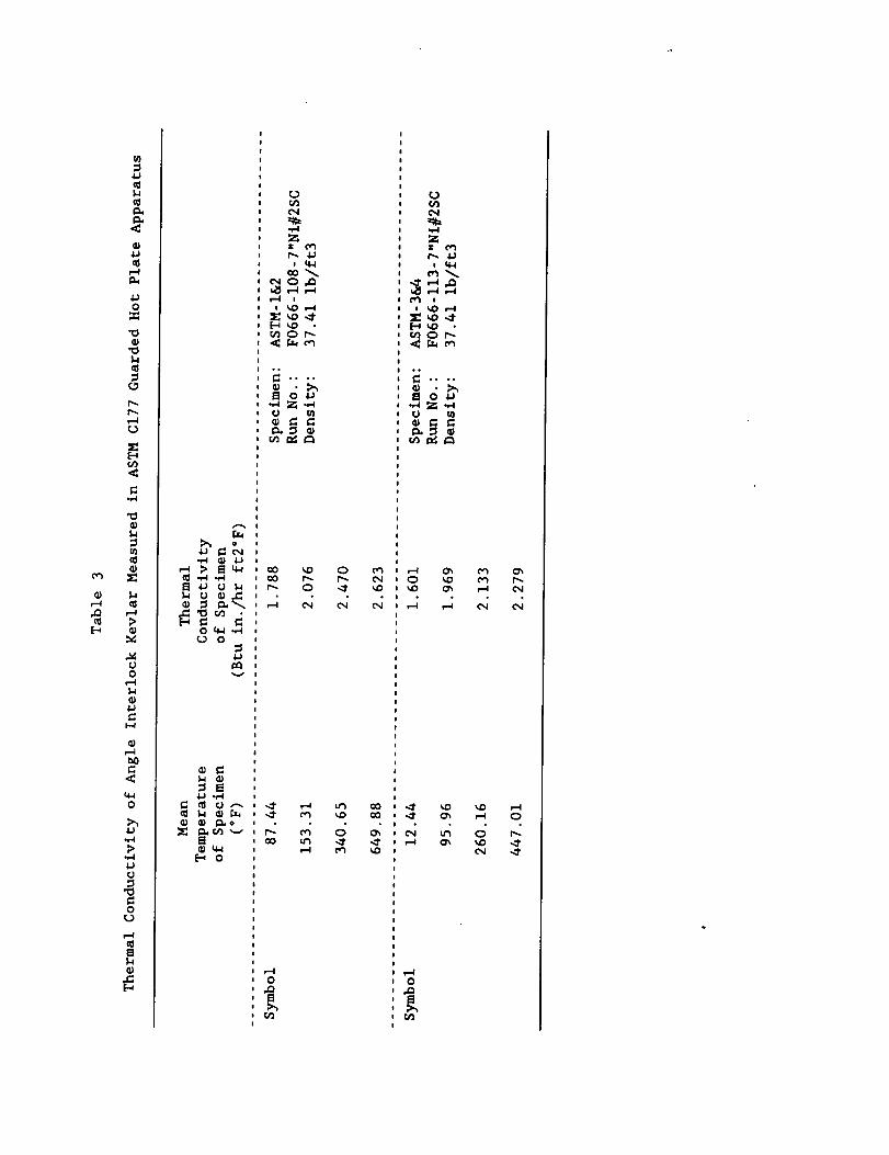
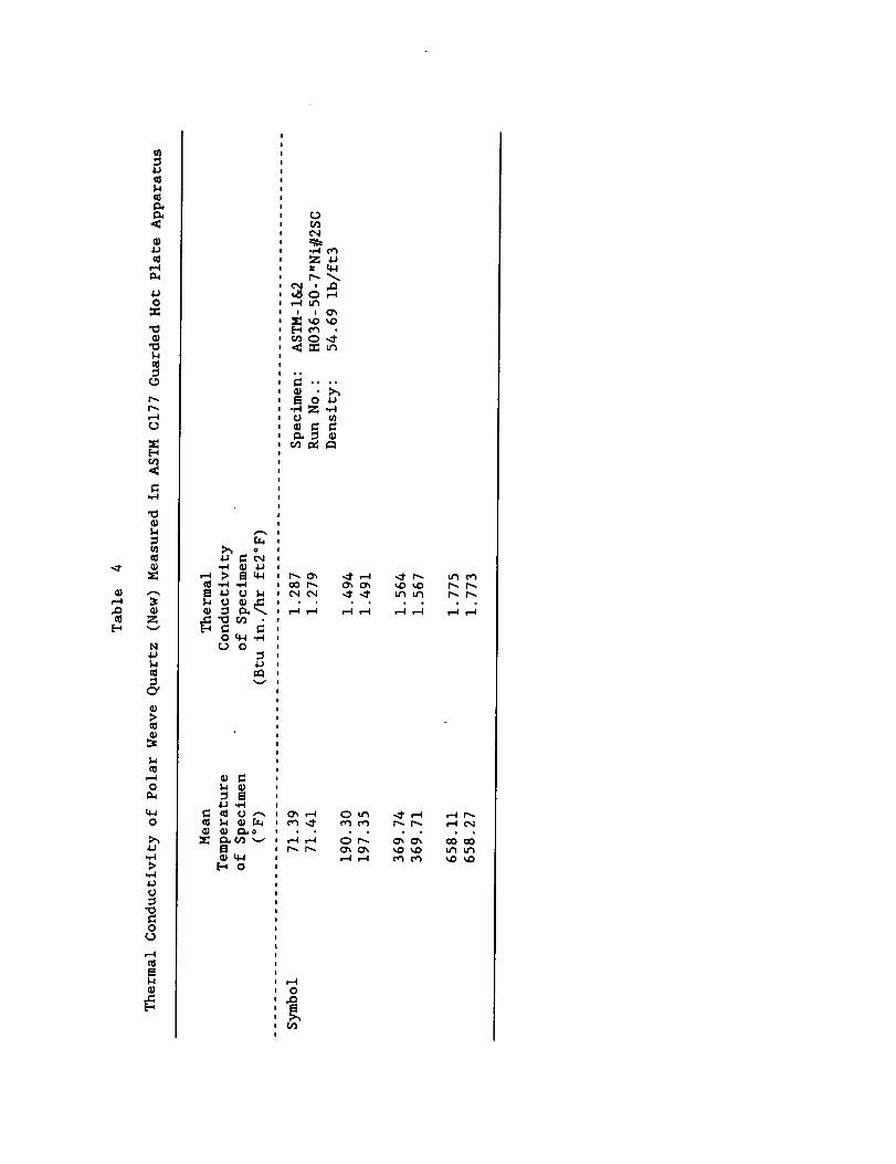
Low temperature thermal conductivity measurements (530 °R to about 1200 °R)
were made utilizing the ASTM C-177 guarded hot plate technique described in
Appendix A. Measurements were performed on all six materials and the collected
data is contained in Appendix B. Figures 2.4 through 2.6 are the thermal con-
ductivity versus temperature curves for the candidate materials. As can be seen,
the thermal conductivity of the polar-weave fabric is slightly less than that of
the angle-interlock fabric. This is fortunate, since the polar-weave fabric is
desired for ASTC design. Tables 2.4 through 2.6 are tabulated recommended values
of thermal conductivity. These tables also contain some extrapolated values that
are necessary for the thermal analysis. These extrapolated values are explained
in section 3.3 of this report.
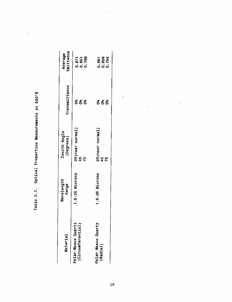
Optical properties (transmittance, reflectance and emittance) were measured
from 1.6 to 26 microns at 530 °R on the polar-weave quartz only. Transmittance
data showed the polar-weave quartz to be opaque so no optical properties were
required on the S-glass and Kevlar. Reflectance and emittance measurements were
subcontracted to Surface Optics Corporation, San Diego, California. Reflectance
measurements were taken at three incident angles in both the circumferential and
radial orientations. Measurements were performed using a Cary-lntegrating Sphere
Reflectometer. Values of emittance were calculated from the transmittance and
reflectance data. Table 2.7 summarizes the optical properties measurements.
Appendix C contains the report from Surface Optics.

5
f
¢5
('8- qI / nl_) lgOH a!_.aadg

I
qI / nl_{) lgOH o!_.oods
g
_D
cD[-
g
.,q
g_
,--4
!
O
U..,..4
...4
¢q,q
mo
m.,
8

Ik
\\\\
\
\\
t )
e_ ¢N]
8
U,,,,,4
,--t
I>
0
_J
U
U
QJ

00
m
¢D
¢-.m
m
¢-
o..
I I I I
v 01_x (_t-lJ-s/nl_) ,(1.tA!l_npuoD IetuJoq,L
8
8
g
.,,,.J
_ t "_,
q)
_ -.44
t4
taO_' ,-,.4
10

/1
\\\\
I I I I
(1)>
t_
ffIm
O£L
o0 _ID ,_. ¢q
v 0T x (N-1J-s/m_t) £1.tA.Tl_npuoDletU:t_qZiI
c)
m
8¢q ¢..1
r4
,J)
0'1
,t.l
.I.3
o
[..-4
o ,,4o0
ill_4
.t-4
c)c,
¢D

¢>
¢00
mI,=.
¢-m
m
¢--,¢
(1)
m
013_
m
I I I I
v OT x (_I-1J-s/nl_/) ,_l._B3npuo::) I_tuzoq_L
¢xl
¢J,,,,-4
,--4
0
,-q
<I?g::
,g
t:a3,w4
12

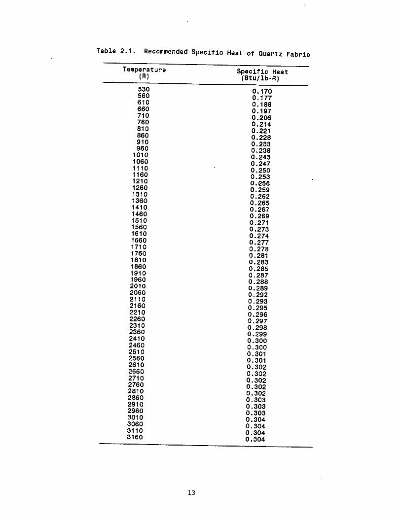
Table 2.1. Recommended Speciflc Heat of Quartz Fabric
Temperature Specific Heat(R) (Btu/lb-R)
530 0.170560 0.177610 0.188660 0.197710 0.206760 0.214810 0.22186O 0.228910 0.233960 0.238
1010 0.2431060 0.2471110 0.25O1160 0.2531210 0.2561260 0.2591310 0.2621360 0.2651410 0.2671460 0.2691510 0.2711560 0.2731610 0.2741660 0.2771710 0.2781760 0.2811810 0.2831860 0.2851910 0.2871960 0,2882010 0.2892060 0.2922110 0.2932160 0.2952210 O.2962260 0.2972310 0.298236O 0.2992410 0.3002460 0.3002510 0.3012560 0.3012610 0.3022660 0.3022710 0.3022760 0.3022810 0.3022860 0.3032910 0.3032960 0.3033010 0.3043060 0.3043110 0.3043160 0.304
13

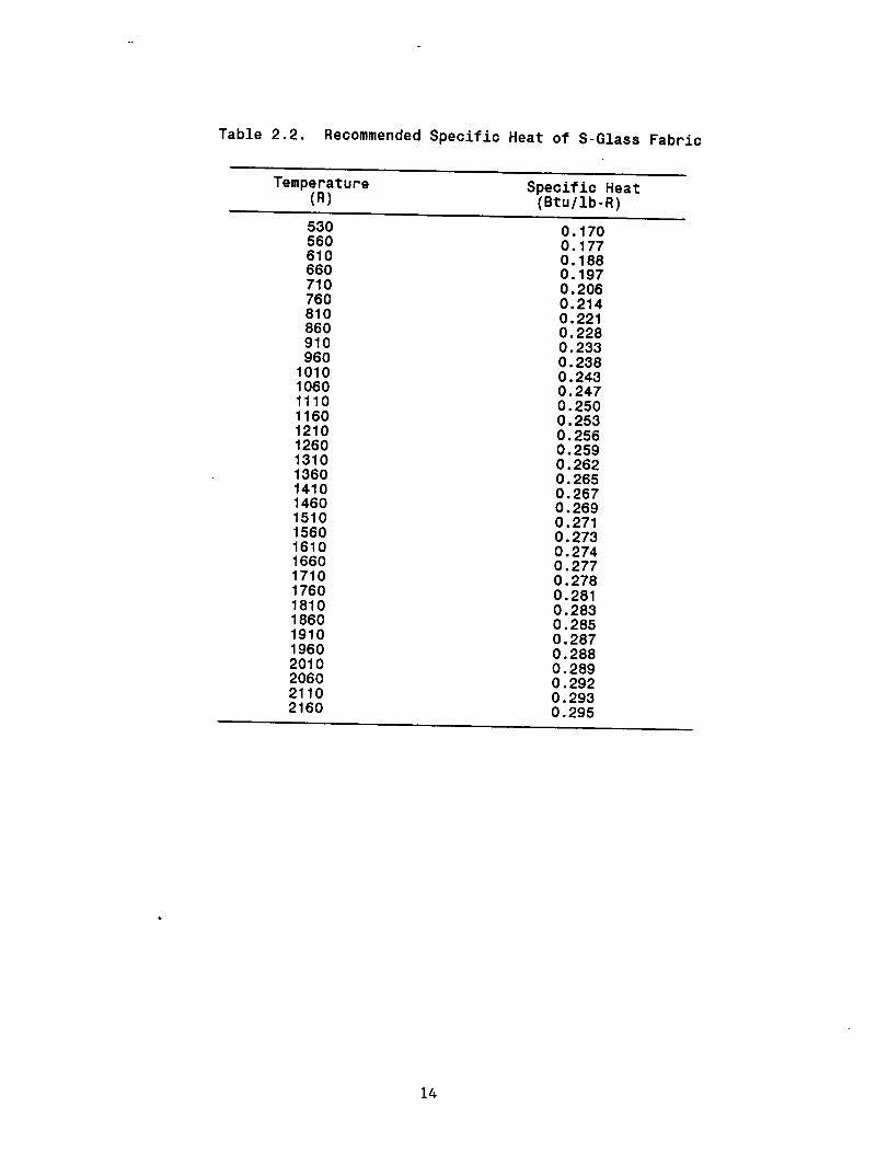
Table 2.2. RecommendedSpecific Heat of S-Glass Fabric
Temperature Speciflc Heat(R) (Btu/lb-R)
530 0.170560 0.177610 0.188660 0.197710 0.206760 0.214810 0.221860 0.228910 0.233960 O.238
1010 0.2431060 O.2471110 0.2501160 0.2531210 0.2561260 0.2591310 0.2621360 0.2651410 0.2671460 0.2691510 0.2711560 0.2731610 0.2741660 0.2771710 0.2781760 0.2811810 0.2831860 0.2851910 0.2871960 0.2882010 0.2892060 0.2922110 0.2932160 0.295
14

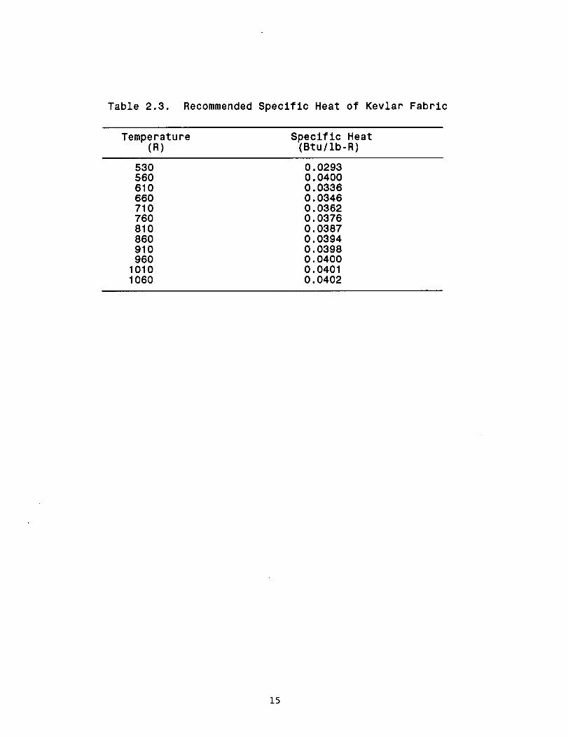
Table 2.3. Recommended Speclflc Heat of Kevlar Fabric
Temperature Speclflc Heat(R) (Btu/lb-R)
530 0.0293560 0.0400610 0.0336660 0.0346710 0.0362760 0.0376810 0.0387860 0.0394910 0,0398960 0.0400
1010 0,04011060 0.0402
15

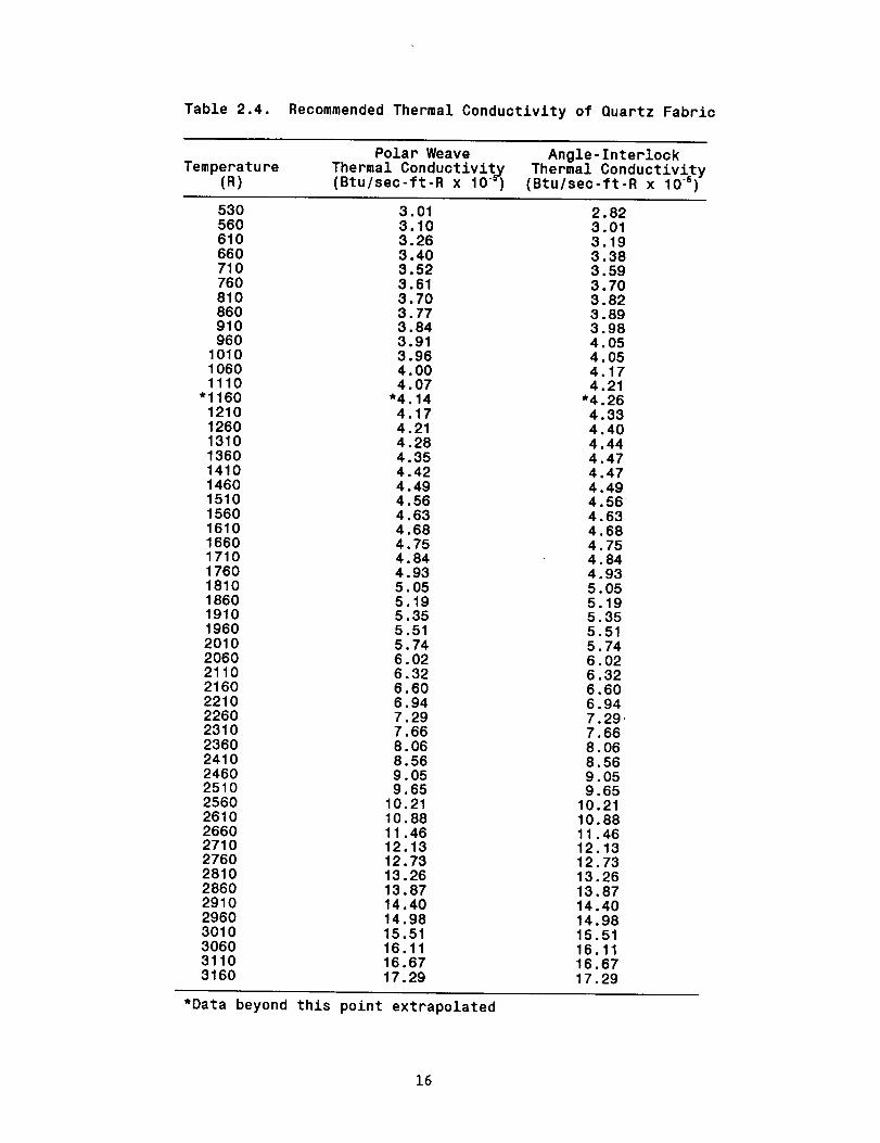
Table 2.4. Reoommended Thermal Conductivity of Quartz Fabric
Temperature(R)
Polar Weave
Thermal Conductivity(Btu/sec-ft-R x 10_
Angle-InterlockThermal Conductivity
(Btu/sec-ft-R x 10 .5 )
530 3.01 2.82560 3.10 3.01610 3.26 3.19660 3.40 3.38710 3.52 3.59760 3.61 3.70810 3.70 3.82860 3.77 3.89910 3,84 3.98960 3.91 4.05
1010 3.96 4.051060 4.00 4.171110 4.07 4.21
"1160 "4.14 *4.261210 4.17 4.331260 4,21 4.401310 4.28 4.441360 4.35 4.471410 4.42 4.471460 4.49 4.491510 4.56 4.561560 4,63 4.631610 4.68 4.681660 4.75 4.751710 4.84 4.841760 4.93 4.931810 5.05 5.051860 5.19 5.191910 5.35 5.351960 5.51 5.512010 5.74 5.742060 6.02 6.022110 6.32 6.322160 6.60 6.602210 6.94 6.942260 7.29 7.292310 7.66 7.662360 8.06 8.062410 8.56 8.562460 9.05 9.052510 9.65 9.652560 10.21 10.212610 10.88 10.882660 11.46 11.462710 12.13 12.132760 12.73 12.732810 13.26 13.262860 13.87 13.872910 14.40 14.402960 14.98 14.983010 15.51 15.513060 16.11 16.113110 16.67 16.673160 17.29 17.29
*Data beyond this point extrapolated
16

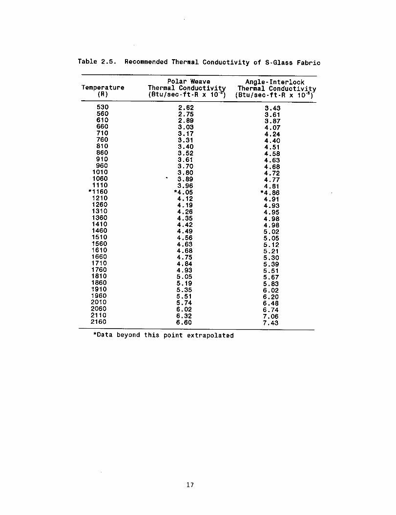
Table 2,5. Recommended Thermal Conductivity of S-Glass Fabric
Temperature(R)
Polar WeaveThermal Conductivity(Btu/seo-ft-R x 10_
Angle-InterlockThermal Conductivity
(Btu/sec-ft-R x 10 .6)
530 2.62 3.43560 2.75 3.61610 2.89 3.87660 3.03 4.07710 3.17 4.24760 3.31 4.40810 3.40 4.51860 3.52 4.58910 3.61 4.63960 3.70 4.68
1010 3.80 4.721060 3.89 4.771110 3.96 4.81
"1160 *4.05 *4.861210 4.12 4.911260 4.19 4.931310 4.26 4.951360 4.35 4.981410 4,42 4.981460 4.49 5.021510 4.56 5.051560 4.63 5.121610 4.68 5.211660 4.75 5.301710 4.84 5.391760 4.93 5.511810 5.05 5.671860 5.19 5.831910 5.35 6.021960 5.51 6.202010 5.74 6.482060 6.02 6.742110 6.32 7.062160 6.60 7.43
*Data beyond this point extrapolated
17

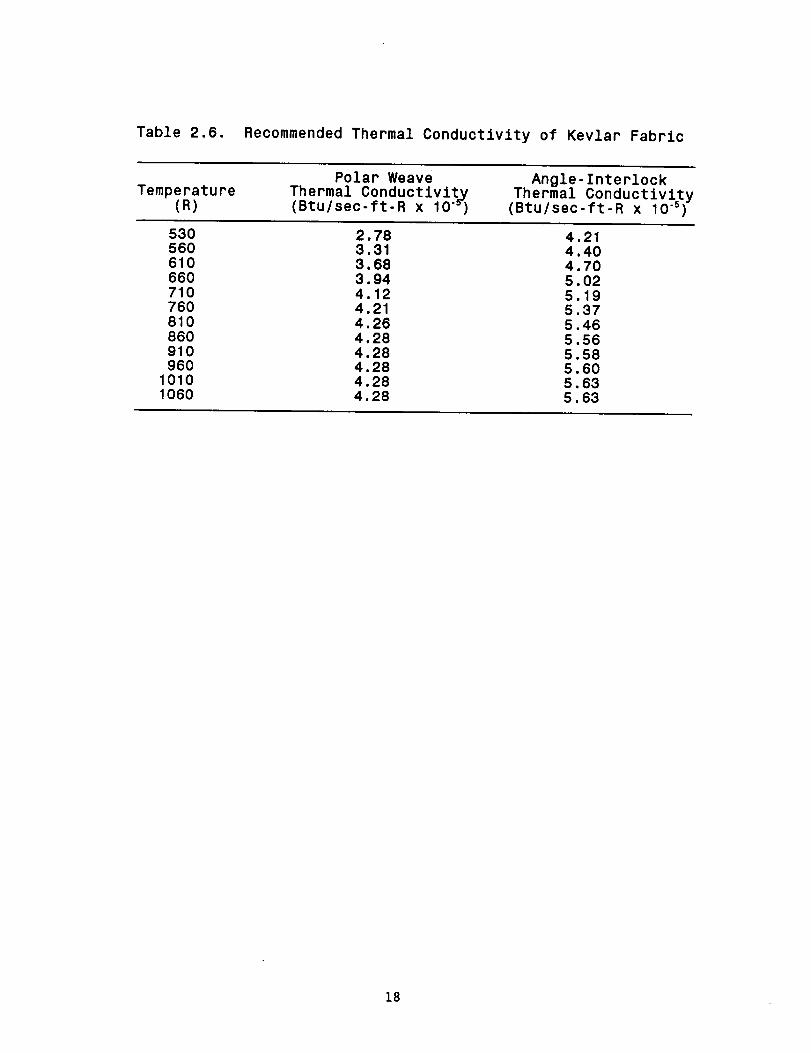
Tabie 2.6. RecommendedThermai Conductivity of Kevlar Fabrlc
Temperature(R)
Polar WeaveThermal Conductlvlt3(Btu/sec-ft-R x 10_
Angle-Interlock
Thermai Conductivlty(Btu/sec-ft-R x 10 .°)
530 2.78 4.21560 3.31 4.40610 3.68 4.70660 3.94 5.02710 4.12 5.19760 4.21 5.37810 4.26 5.46860 4.28 5.56910 4.28 5.58960 4.28 5.60
1010 4.28 5.631060 4,28 5.63
18

u')
m
co
r..G)EQ)L
com
:S
.,-I
L.
Q.0c.
Q.
,-I
u.,-I
Q.O
Cd
a_
caF-
r.3
ramL.I-I
_Ew
u
+_.,-IE
t-
C.
a_
c m_aJ
..c L.I_
e- r'._
N
_mc: c3_
cm
m
m.,-IL
m_E
oO 00 I_
000
0
A
mEC.0
¢.
c
0 _') u3
_.-oLu
-_1
_Doq
|
co
N A
Lc_._l
0 r-
, U¢,. L
n
000
s0s0 O0
A
m
f_o
t_
0 L_ U';C_ q" r,..
m
oLo
.,-I_E
0,I
N
t_m
0
.,.4
e_
i9


2.1 CONCLUSIONS
Since the polar-weave fabric was the fabric of cholhe for construction of
an improved ASTC, and since the thermal conductivity of the polar-weave fabric
was less than or comparable to the angle-interlock fabric, it was decided to
perform all further tests and analysis on curtains employing the polar-weave
constructions.
20

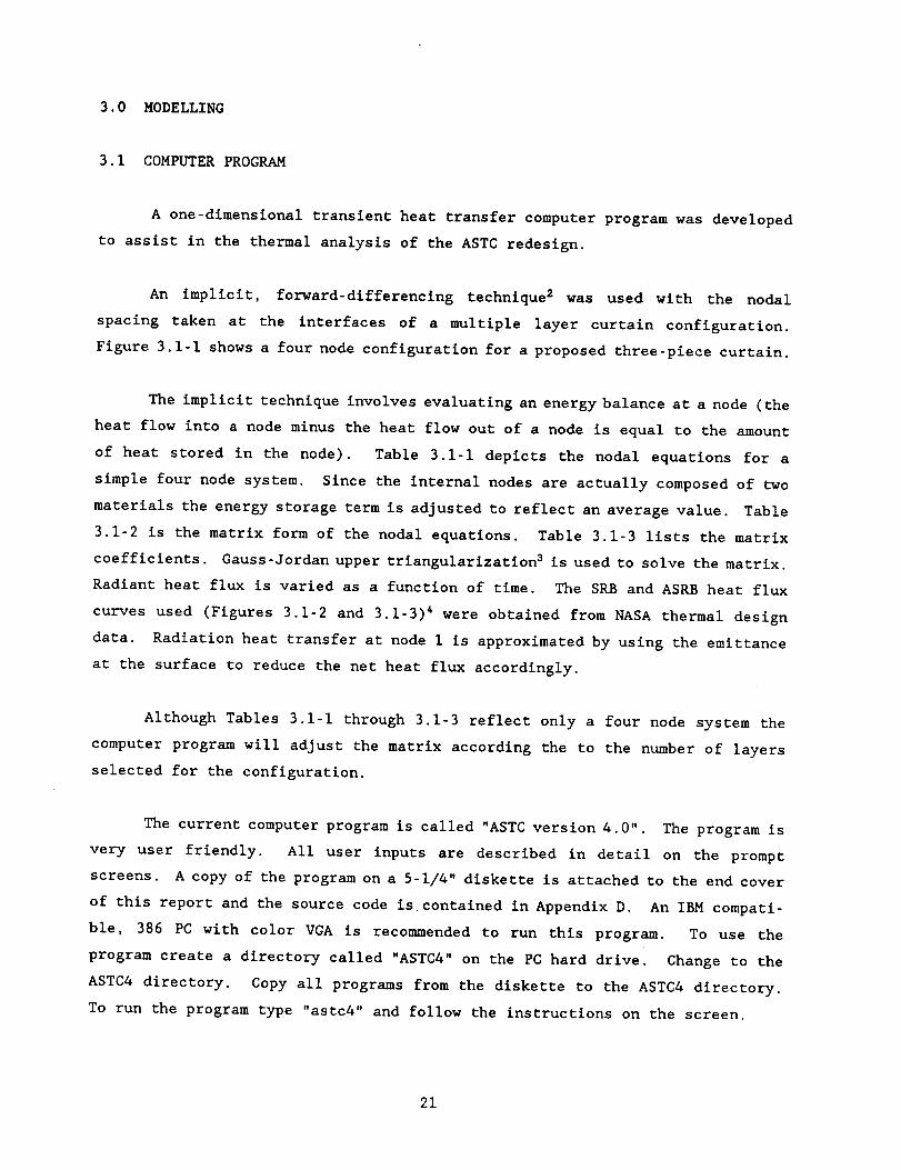
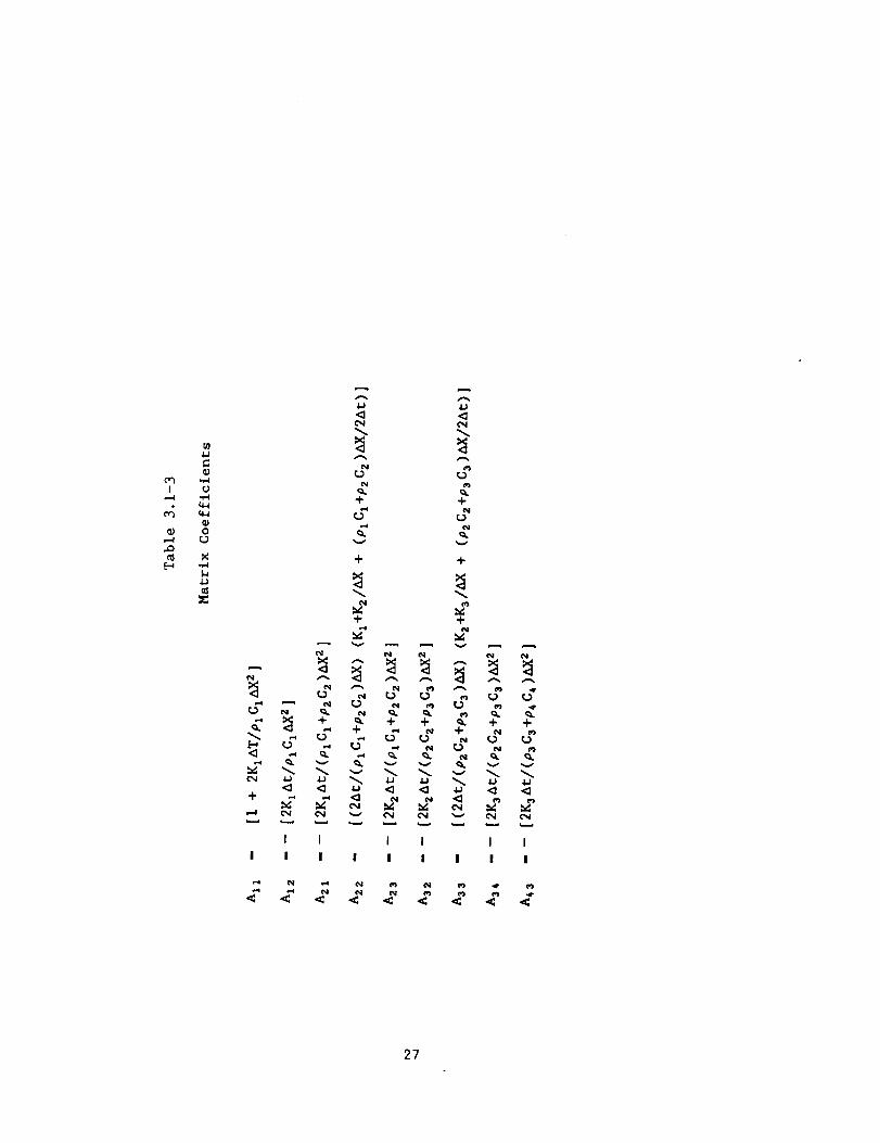
3.0 MODELLING
3.1 COMPUTER PROGRAM
A one-dlmensional transient heat transfer computer program was developed
to assist in the thermal analysis of the ASTC redesign.
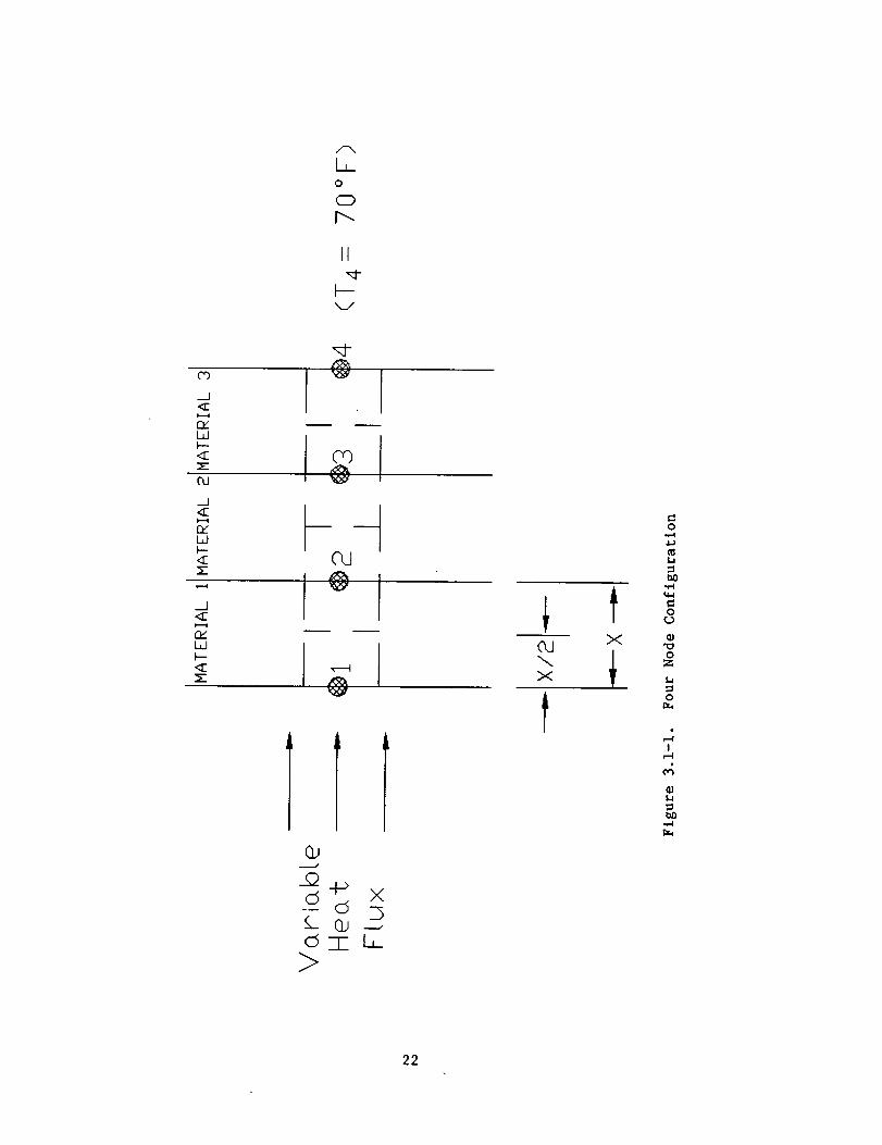
An implicit, forward-differenclng technique 2 was used with the nodal
spacing taken at the interfaces of a multiple layer curtain configuration.
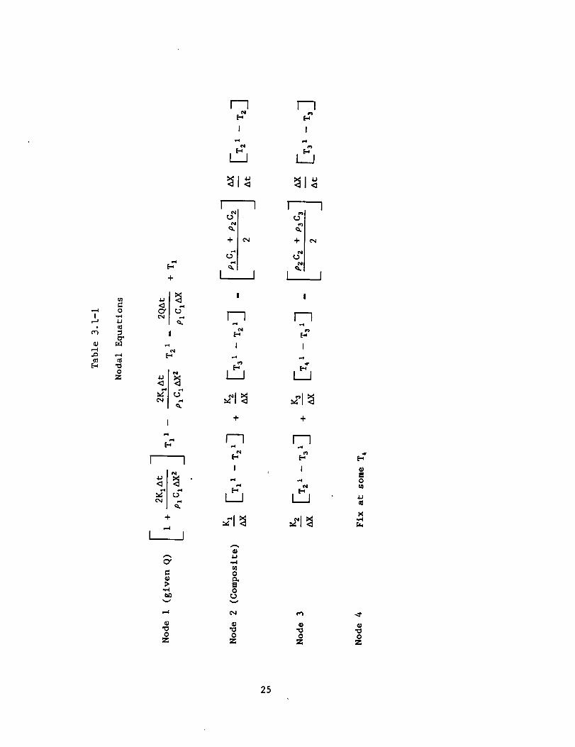
Figure 3.1-1 shows a four node configuration for a proposed three-piece curtain.
The implicit technique involves evaluating an energy balance at a node (the
heat flow into a node minus the heat flow out of a node is equal to the amount
of heat stored in the node). Table 3.1-1 depicts the nodal equations for a
simple four node system. Since the internal nodes are actually composed of two
materials the energy storage term is adjusted to reflect an average value. Table
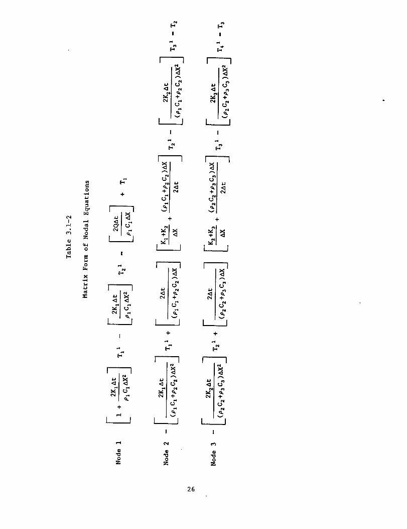
3.1-2 is the matrix form of the nodal equations. Table 3.1-3 lists the matrix
coefficients. Gauss-Jordan upper trlangularization 3 is used to solve the matrix.
Radiant heat flux is varied as a function of time. The SRB and ASRB heat flux
curves used (Figures 3.1-2 and 3.1-3) 4 were obtained from NASA thermal design
data. Radiation heat transfer at node i is approximated by using the emittance
at the surface to reduce the net heat flux accordingly.
Although Tables 3.1-1 through 3.1-3 reflect only a four node system the
computer program will adjust the matrix according the to the number of layers
selected for the configuration.
The current computer program is called "ASTC version 4.0". The program is
very user friendly. All user inputs are described in detail on the prompt
screens. A copy of the program on a 5-1/4" diskette is attached to the end cover
of this report and the source code is contained in Appendix D. An IBM compati-
ble, 386 PC with color VGA is recommended to run this program. To use the
program create a directory called "ASTC4" on the PC hard drive. Change to the
ASTC4 directory. Copy all programs from the diskette to the ASTC4 directory.
To run the program type "astc4" and follow the instructions on the screen.
21

A
L0
C)
r--
ii
x_/
¢0
<E
r_Wh--<=
OJ
<=
_ELdh-
<E
J<E
nl
w
CO
@
I
22
CO X
X
Co
=
Co
oZ
=o
I
4

:3_S _L4E)S/ _iE[ - ±OC[ 0
r._
¢I
0
0
.I.IU
Itl
I=II,.,.4
I,¢
r._
_qI
,4
I.I
23

f
fJ
24

,--4!
E_
m
0
h.1
,.-4
0Z
eq
I
I I
+
i-,4
L_I
A
C_
v
0Z
I
I i
I I
F--1o-e
N
I
F_
I
I i
I
I i
A
J_
0
0
V
0Z
0Z
0m
X
r_
n_o
z
25

C'NI
Q;
O
4.)
OZ
q-4
O
O
X
4J
x:
+
i I
!
p'4
N
I i
I
÷
,-4
I I
OZ
!
o4
N
v
I
v
÷
I _ I
e4
N
k______]
÷
r--1
_ N
e,4 ÷
k__ _..J
0Z
!
N
L_.J
I
v
÷
I _ 1
N
N
v
+
E_
N
A
r_e4
v
L___
OZ
26

I
,--I
(0
O
_s
N
÷
I
! !
c',,I
q.÷
v
÷
N
"i-
v
C.) Nr_
c_. N
÷
v
<_
c_v
I
I !
<_
A
r_
-i-N
(.)
v
÷
N
N A
N _ r__
+ +
N
N
N N "_
I I
! I !
eg
÷ -t-
e¢
v v
<_
i I
! I
27

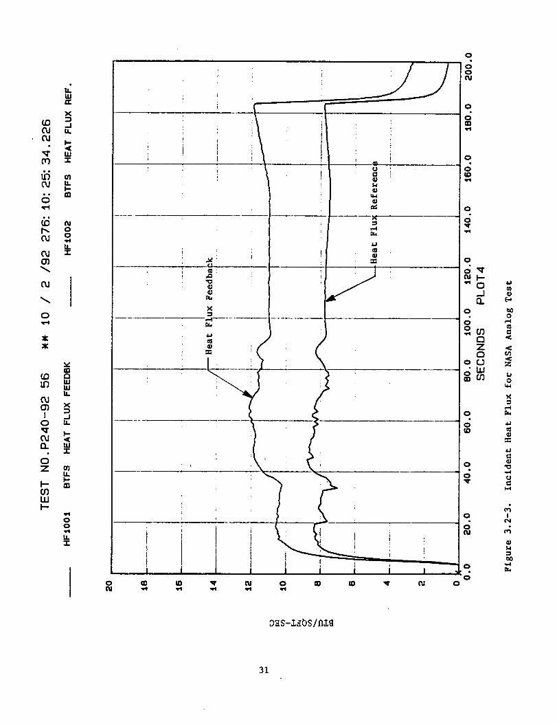
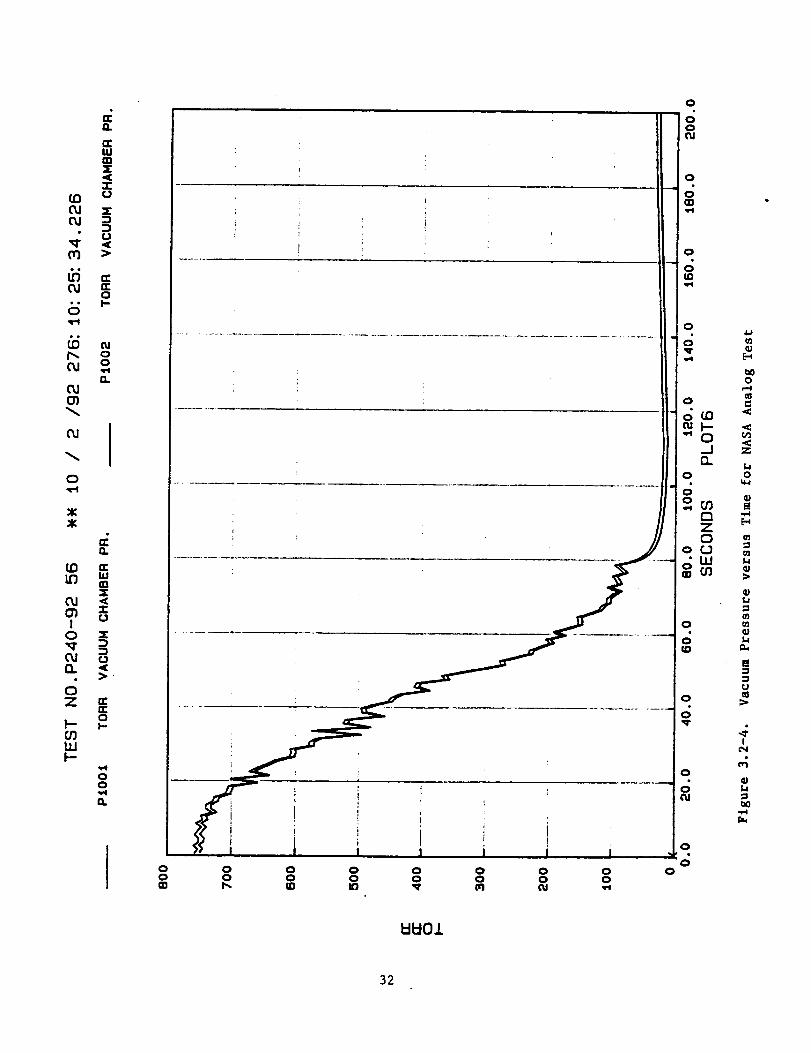
3.2 ANALOG TEST FACILITY
A quartz lamp thermal flux facility was developed to perform actual tests
on curtain configurations constructed by B.P. Chemicals. Figure 3.2-1 is a
schematic of this test facility. A sample curtain 12"x12" can instrumented with
thermocouples on the surface and between layers and then exposed to either an SRB
or ASRB flux shown in Figures 3.1-2 and 3.1-3. A calibrated heat flux transducer
can be used to control the flux from the quartz lamps. Data is recorded continu-
ously by a data acquisition system. Data are presented in the form of tempera-
ture-time plots.
Some analog testing was also performed independently at NASA/MSFC although
only for the SRB flux. A schematic of NASA's analog test setup is shown in
Figure 3.2-2. Two blankets are run simultaneously in the NASA facility with
thermocouples placed on both the right and left sides of each blanket. The NASA
facility does not possess the capability to simulate the SRB flux. Instead, the
area under the SRB flux curve is determined and a lower flux is applied for
sufficient time to achieve the same integral area. Figure 3.2-3 is the flux
applied in the NASA test. Note that the heat flux feedback is measured with the
blanket in place while the heat flux reference is measured by a radiation
transducer without the blanket. NASA's test setup also allows simulation of the
change in pressure the ASTC would experience as the booster climbs through the
upper atmosphere (Figure 3.2-4). Data are recorded via an acquisitioner and
include incident heat flux, pressure, and temperature as functions of time.
28

aJt:0
"o
0
0
o
+
@
(3130[30O[3DO
_J
i---I
i-,-I
t_
[-_
l'44Jt_
O"
0
0
c_
0
I
<4
_8
29

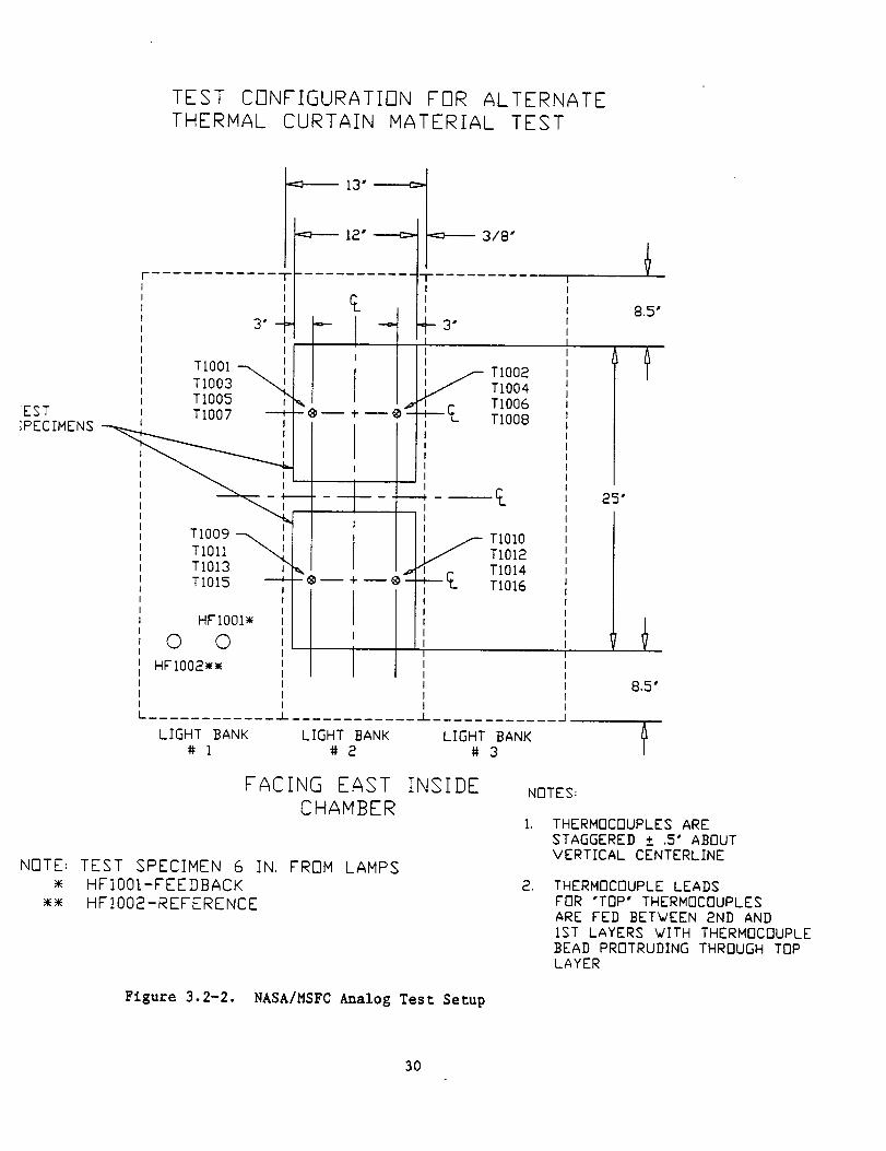
TEST CONFIGURATION FOR ALTERNATE
THERMAL CURTAIN MATERIAL TEST
"=_-- 13" ------_"
_ 12" ----c>F
s'+ --- qIII I
TIO01 -_TIO03
TIO05 _,EST TIO07 ---_- ® -- + @d
;PECIMENS _+__ t
I I
TIO09 -_TIOII
TIOI3 ITIOI5
HFIO01_
© © ,i
HFIO02_
3/8"
III
H s"
-®-- +--@--_--_I
I
i
IIIIIIi
I........ _.l .....
I
jf_,,,_ TIO02TIO04TIO06
T "-_- TI008III
III
ItI
I_ TIOIOI TIOI2•_I TIOI4
TIO1G
LIGHT BANK LIGHT BANK LIGHT BANK
# i #2 #3
25"
FACING EAST
CHAMBER
NOTE: TEST SPECIMEN 6 IN. FROM LAMPS
HFIOOI-FEEDBACK
• _ HFIOO2-REFERENCE
INSIDE NOTES:
THERMOCOUPLES ARE
STAGGERED ± .5" ABOUTVERTICAL CENTERLINE
, THERMOCOUPLE LEADS
FOR "TOP" THERMOCOUPLES
ARE FED BETWEEN 2ND AND
IST LAYERS VITH THERMOCOUPLEBEAD PROTRUDING THROUGH TOPLAYER
Figure 3.2-2. NASA/MSFC Analog Test Setup
30

(,DCLIC"d
00
OJil
O
O,J
O
:¢:
COI._
CLIO%I
O
n
OZ
I.-O31.1.1i--
W
X
-I
W
I.I.
O400,,el
14.
v
WW
X
J
I-.
l&.l
00
0
O
i b
L
O
I
_4-j
I.I
I,l.I
,m
IiI
iID
OO('U
O
O_D
O
OIO
O
O_rm,q
O
o'q"
O_Jn
O
. ZO
o.
i °O
O
o0
03
E_
bOo
o'3
u0
u_
c_
4=,I
_3
rJ
I-4
I
M
31

Q.
n-IIi
(O oO,I x
• U•q- ._0r3 •
OJ n-O
• o JD
O
p,. oO.I o
13.CU(31
°1O
_KX
n
(D rrLL'J Lu
rn
IO x
• • -
OZ _
O
ItlI--
00
el
OO
OOt_
00
00
00
0
32
0
0o
0
0
0
0
0
0
0
0
G'I
o
e_
Z
o
O3
O3L,
O3
_Jt..I
:3
r.J
IOq
_)

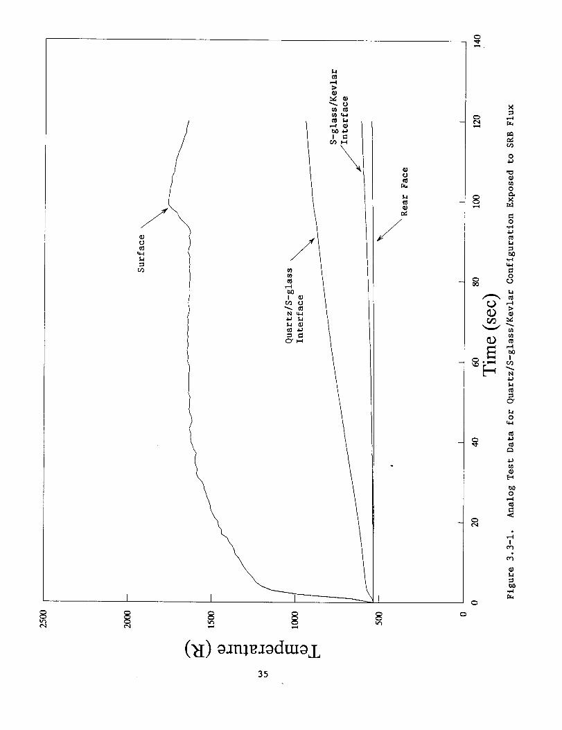
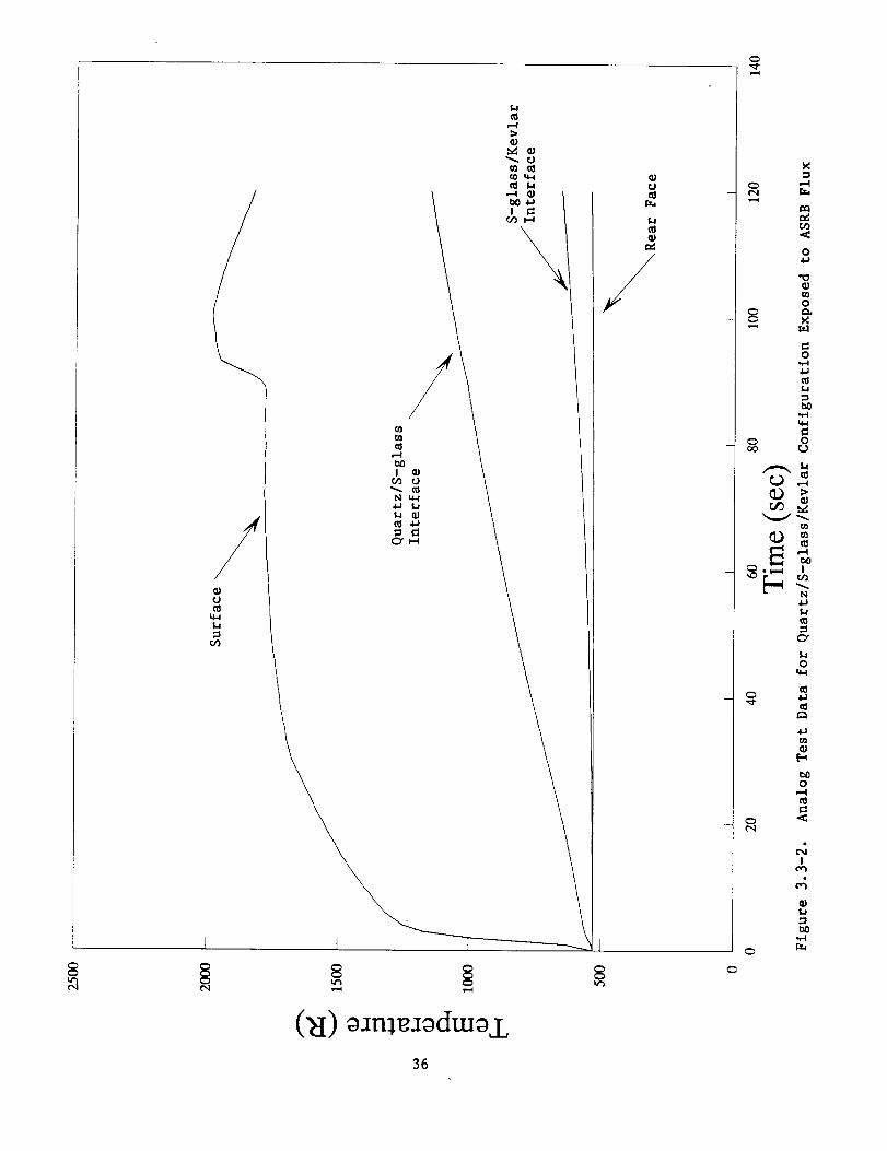
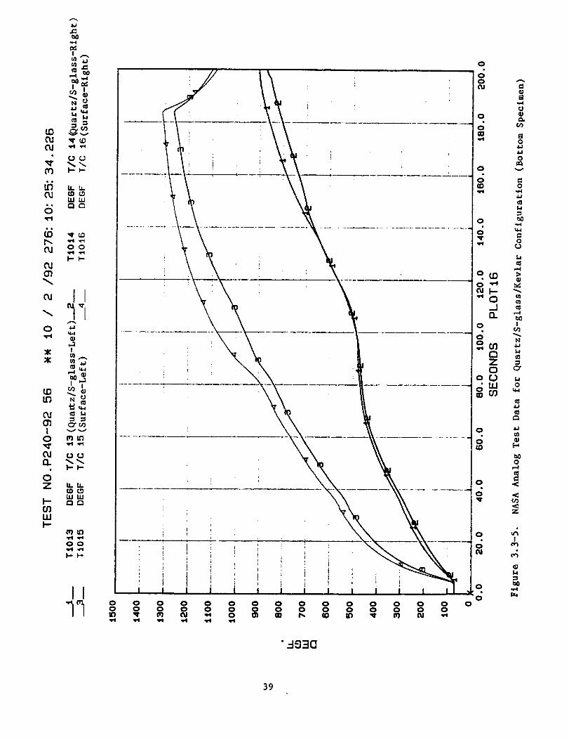
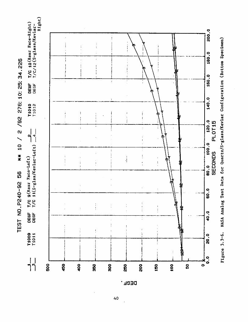
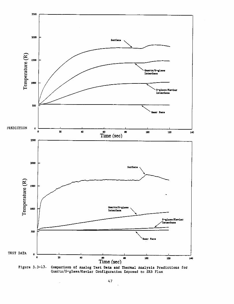
3.3 RESULTS AND CONCLUSIONS
Samples of polar-weave quartz, S-glass and Kevlar, cut 12"x12", were sewn
together to form a three-piece curtain for testing in the quartz lamp facility.
Although this curtain design is twice as heavy as the current ASTC design (about
1150 Ibs versus 600 ibs, not considering hardware installation tradeoffs) the
analog data from this particular design can be used to validate the computer
program. The sample was instrumented with three thermocouples and exposed to
both SRB and ASRB design fluxes for 120 seconds. Three tests were run. Figures
3.3-1 and 3.3-2 show the average thermal response with exposure to SRB and ASRB
fluxes, respectively.
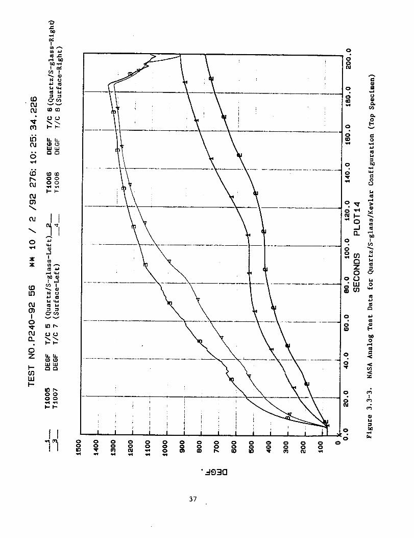
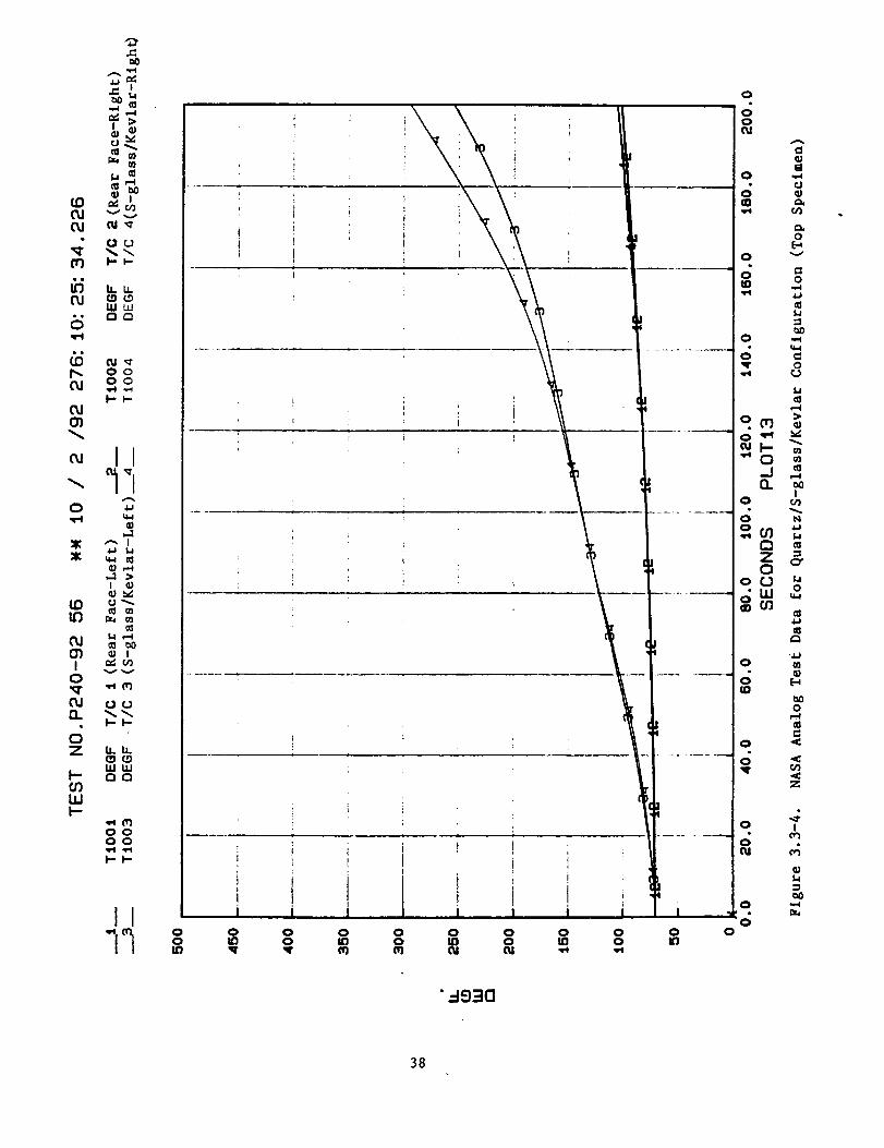
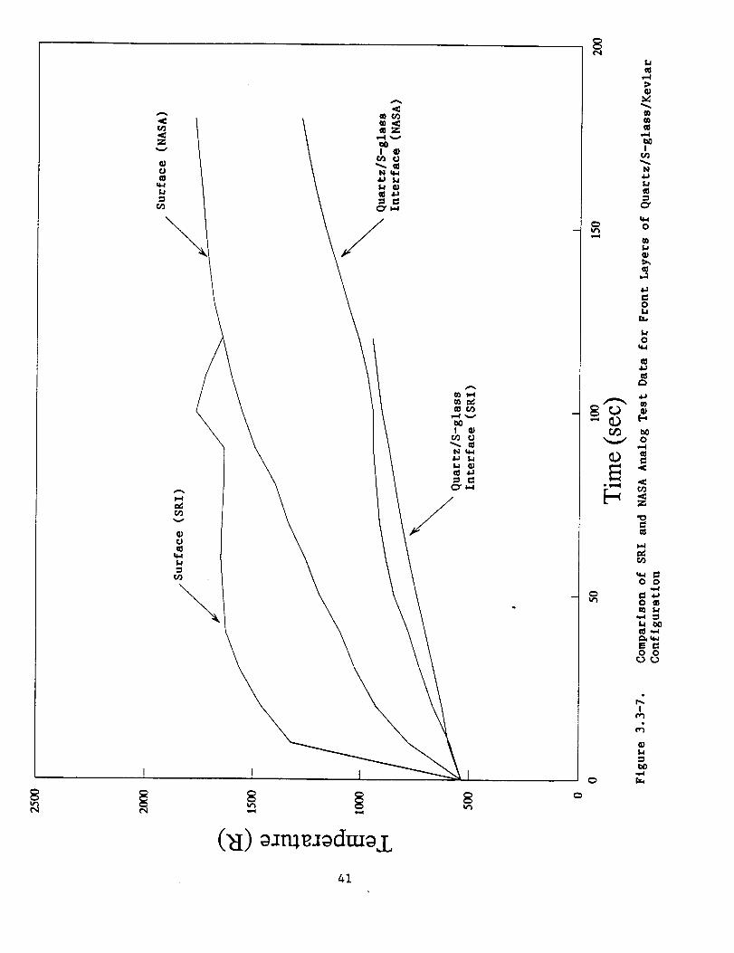
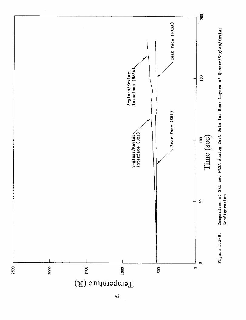
Figures 3.3-3 through 3.3-6 show the temperature-tlme data collected in the
NASA facility and Figures 3.3-7 and 3.3-8 compare SRI to NASA data. NASA's
surface data is considerably lower than SRI's up to 120 seconds. However, NASA's
incident flux was much lower than the SRB flux used in SRI's test and surface
temperature variations are to be expected. Note that NASA's surface temperature
reached about the same maximum as SRI's but took longer due to the lower flux
levels. NASA's data is in excellent agreement with SRI's data for the interior
and rear face positions up to around 120 seconds. NASA's maximum temperatures
for these positions are somewhat higher than those reached in the SRI experiment.
However, due to the lower flux level, NASA's test duration must be considerably
longer than SRI's in order to achieve the same area under the flux curve. This
additional time allows the blanket to heat longer and is probably the cause of
the higher temperatures. Overall, NASA's test would seem to confirm the data
taken in SRI's analog test.
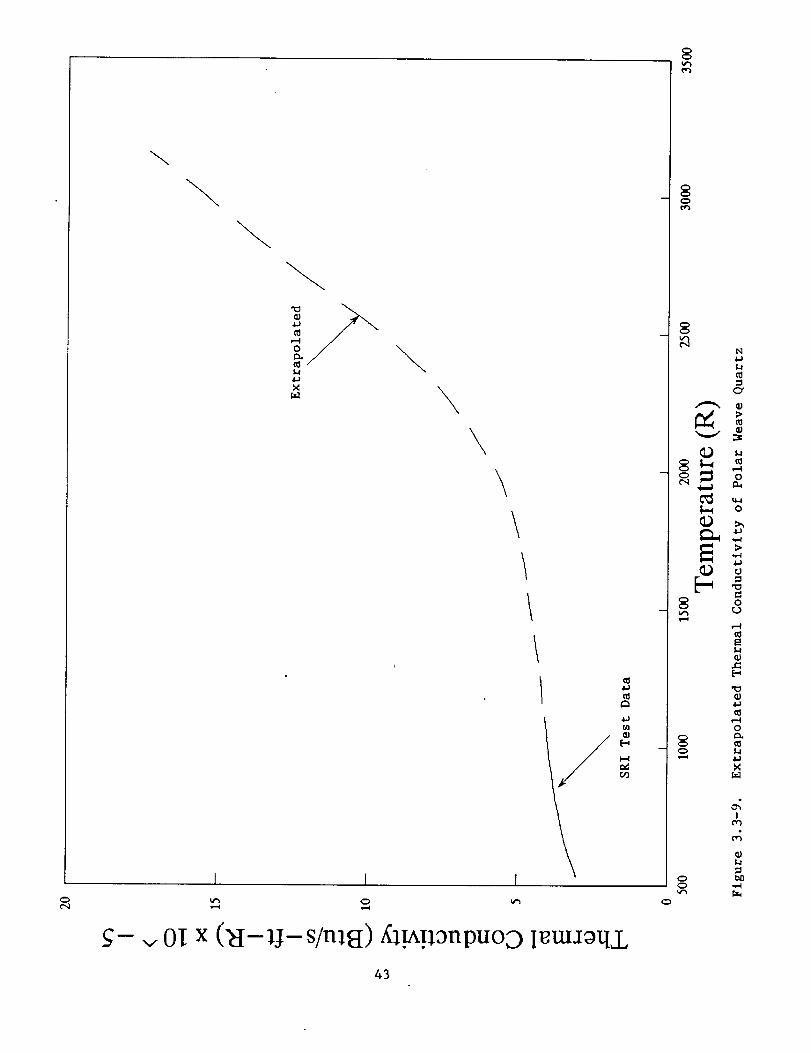
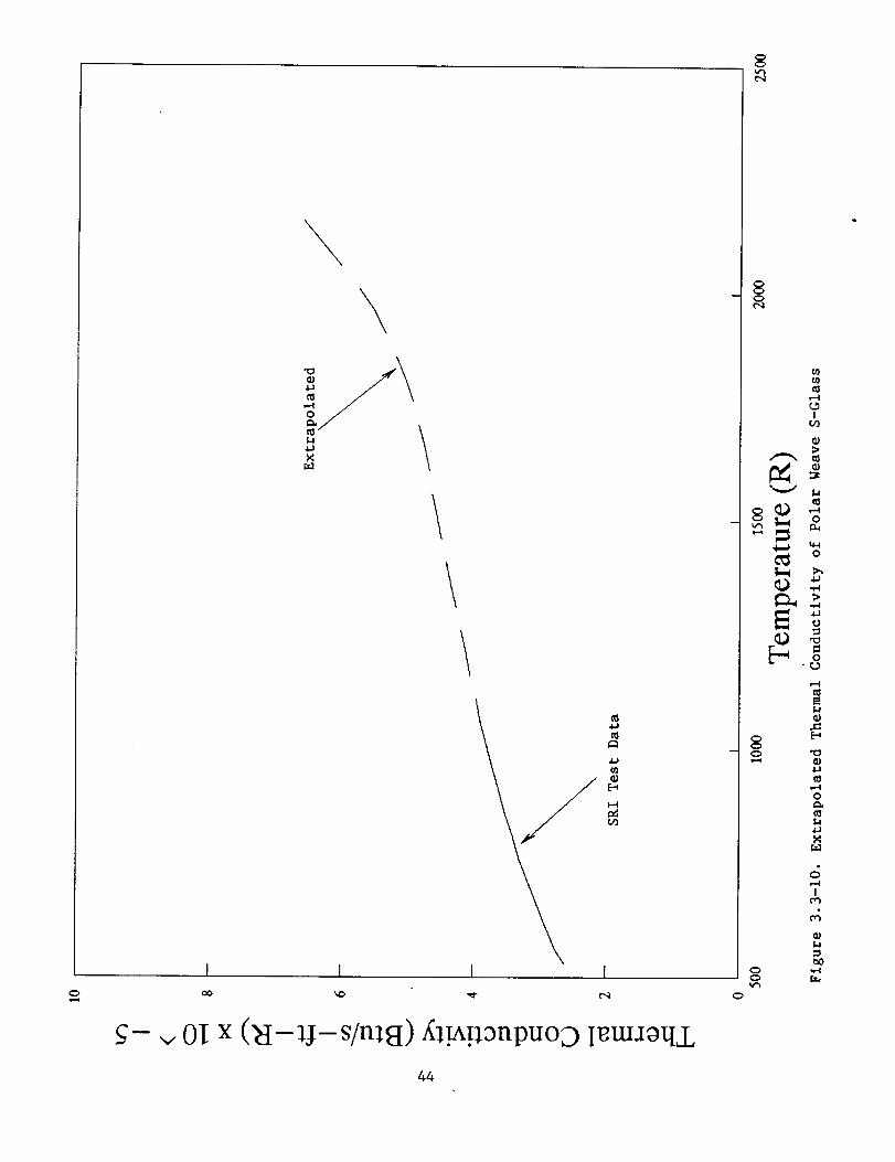
Next, the computer program was used to perform a thermal analysis on the
three-piece curtain for each flux. Since elevated temperature thermal conduc-
tivity was required on the quartz and S-glass an approximation had to be made for
these values. Figures 3.3-9 and 3.3-10 represent the approximations selected for
the most probable high temperature thermal conductivity of the quartz and S-
glass. These values are marked with asterisks in Tables 2.4 and 2.5.
33

It was estimated that the incident radiation on the ASTC from the rocket
motor plume would be approximately 45 degrees 5. Therefore, an emittance value
of 0.85 was selected (see Table 2.7) for the analysis.
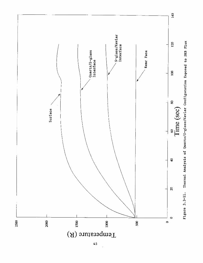
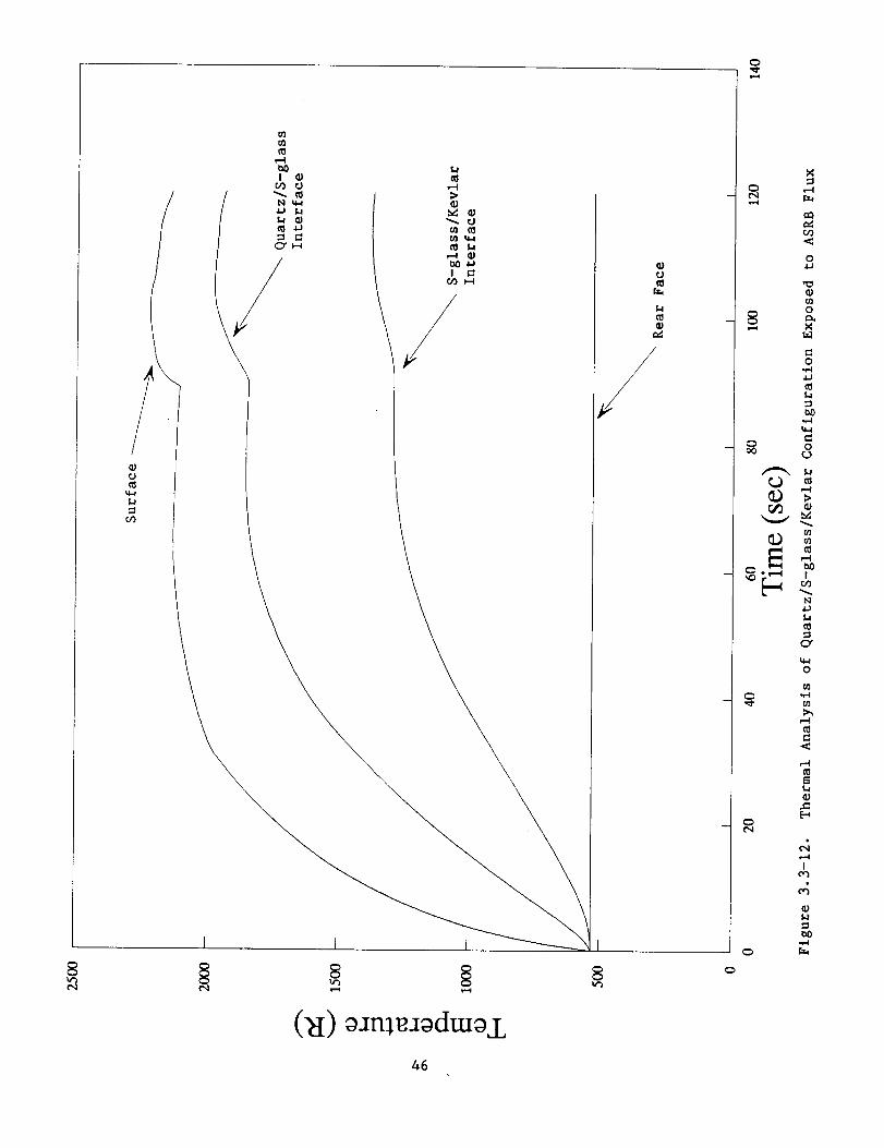
Figure 3.3-11 presents the results of the thermal analysis for SRB flux and
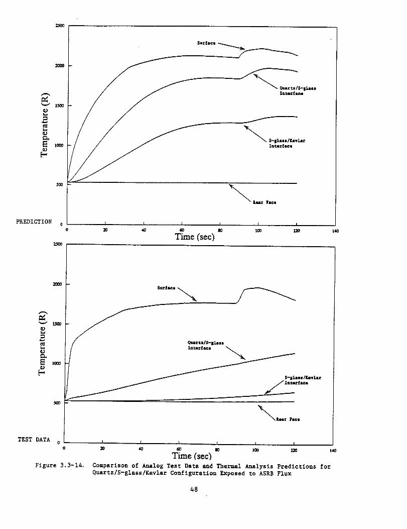
Figure 3.3-12 shows for the ASRB flux. Figures 3.3-13 and 3.3-14 compare the
analog test data and the thermal analysis data for each flux. The surface
temperature predictions are within about 20% of the analog data. Considering the
limitations of the finlte-differenclng techniques used, plus some necessary
simplifying assumptions made by the program (constant surface emissivity,
constant rear face temperature), this is reasonable agreement. The analog inter-
face temperatures were much lower than the predicted temperatures. The computer
program has no provision for inputting interfacial resistances that are present
in the analog test which probably accounts for the discrepancies.
The surface and rear face temperatures are the controlling design param-
eters for the ASTC. The computer program yields a conservative result for the
surface temperature. However, caution must be exercised in examining the as-
sumption that the rear face will remain at 530 "R. The program predicts that for
thinner blankets, the surface and internal temperatures will be lower while the
rear face remains at 530 °R. This is not the case. For thinner blankets, the
surface and internal temperatures will indeed be lower, but the rear face will
experience a greater temperature rise (see section 4.0 for an example). For a
very thin blanket, it is possible that the program would indicate an acceptable
design when the rear face temperature actually rises above acceptable levels.
The computer program appears to be a viable tool for the preliminary
screening of possible ASTC configurations. For a more accurate determination of
the configuration's rear face response, analog testing or a finite element
analysis is recommended.
34

_J¢M
u3
fJm t_
VO .I-_I
\
_0I
N t_4
I..I a)
CX_
1/
(N) _Jnl_dmaj_
¢Jm
0_
/
I
0
0
0
0
0
0
LI_ m
0
0
m
Io_
_0
35

(_I)_m_dm_±
¢J_I
I-IIll
/
,-4¢q r._
b')
0
0
8 _
0
_ 0
N.l.J
Ce
0
f/l¢}
F_
0,-_
Cq
I
36

!
_0 .-,.4
c,2 !
N ¢J
L. v,._
fU _m
• l,J_
_ ,,u.W_
p_ Oo
X I
c0 I
0
° I--I-
oZ u.u.
wm
ffl
m_oooo
II00
qH
00_r
0o
oo0dxr_
, o
i o
' ii , i
_ oo° o _ °o oo °o °o °o oo oo °o o":;
37

(D
CU
.q.
CU
I"-OJ
CUO_
CU
0
Z
(U
I0
n
0Z
I--
111I--
_)
Q)
u
I.I ¢I
f3_
l-I-
h U_
I.UWl_rn
O0O0'e4 ,_
I-I--
II7"7
_'_ I
_,.._,-_ _,I G}
U_
C__=_
_0I
_._
,,.S Cr_
l-.b=
WWO0
_.i (11O0OO
I-I-
II "_--'--- "---__ o o o oI! 0 l_J 0 E'J
tO _r _r (11
ooi11
o o o oID o I_ 0
0ID
0
o
o_
°io
g
o =o_ _
°_
o _'
°_
o _
0 I• 0-1
0
0 ",'4•
0
38

.c:
.,q
,^a,J
t_ ¢J
C_J _r_
• (.,1 r..j
F1 I--_-
,,,,C9C_LUW
°° C3_o
o_I-I-
O)
I !
N _Jlrl t:t_
0Z _u.
w
mw
Oo
II77 0 0 0 0 0 0 0 0 0 0 0 0 0 0 0 0
0 0 0 0 0 0 0 0 0 0 0 0 0 0 0
"_930
3g

C_J
eO
GJ
O1
O
ZX
ID
I0,_.
n
0Z
I--
WI--
.i.i I _o
,.4
I a)
u_co o_
I_ cooll
I..I _-4co DOoJ I
C..1U
U.h
tLlUJaO
q,I ,,_
OO
I--_-
II
A
.8..I
0J
U-4
,-4ia _0
_Vv
UU
!-I-
(.0c0hllllr'lrl
0','_O0
I'-_-
IIOO
O O O OO L_ O
O O O Olid O It] O
O O
o.
o
" o"
o. ovo o:
o
:o
o -o "_
Ct'J
O .s_• 03
o
o _
o ,g• I
0 _
:3O _0
O
40

! I I
(N) o:_m_aodmo,Z.
ta¢0
,.-i
o
m
I
N
I.i
O"
_ _ o
o
oI..i
t.Io
_ _,'_, _
Z
i,-i
o o
v_ 0m
o o
Io_
41

I I I
('et) oam aodmoj
42
Zv
cq
o _.l.i
m
co
!c_
eq
o
O_
co
o
0
c_
Z
co
c_
o o
om
o o
!
,q

\\
X
\\
\\\
1 I I
t_
N
0"
o
'x3
0e_.
I
,,4
,. Ol x (_I -13- s/nl_/) ._l._.tl3npuoo I_ta_Oq,L
43

\
I I
\
0
t_
X \
\
I I
0
!o9
__¢_ o
0
0
0
f_.IJ
I
,4
bO
0 [z_
0
m v OT x (_I-1J-s/nl_/) ,_l._!13npuoD TmU:_oqi
0
44

/'4.4
r..O
I I I
1¢3
(_I) o:mle:Iodmoi
-- C_
O0
O_
0
nDOJ
8 o
0
- _ 0
ffl
N
0
_a
I
,,,-,I
45

¢.J
t._
I_,_ _J
N q-4
_ U
I13 I.I
I_) _-_
I I:
I I I
(_I) oJnleJodmo±46
¢.J
/
X
.<:
0
,._
0
_ N
0
o._ 0
eN ,bl
0
Ul
O..<
e"
I

25OO
2OOO
L_O0
L=
5O0
PREDICTION o
f
_sr.em_sce
_'_ S-81ass/r, evlaz
Int.e:face
I I t I I
Time (sec)
I
12o 140
2OOO
1500
C_I.dCD
E ]ooocD
f.,co0 -
TEST DATA oo
Figure 3.3-13.
Ommt.z/S-$1sa=
Znr.a.-'lace _,_
I
S-S).um I]_evl_:
IuCecfsce
I I I I I I
_ _ W 1_ 12o
Time (sec)Comparison of Analog Test Data and Thermal Analysis Predictions for
Quartz/S-glass/Kevlar Co_figuratlon Exposed to SRB Flux
14o
47

2OOO
c_
2
,me
5OO
PREDICTION o
//
Io
Sacfsce --.,.._..,_..,_._._
Quar _z/S-s_asoZn_rfaeo
f
_ S-S].usll_vlar
Intar£acs
I I [ I 1 I
20 40 60 80 100 3.20 L40
Time (sec)
2OO0
v 1500
t_.,
D
cD
,ooo
TEST DATAo
Figure 3.3-14,
Qurtz/S-l_l_ssl_ter_e
I
S-s_sll_,v_ar
I I I I I I
Time (sec)Comparison of Analog Test Data and Thermal Analysis Predictions forQuartz/S-glass/Kevlar Configuration Exposed to ASRB Flux
48

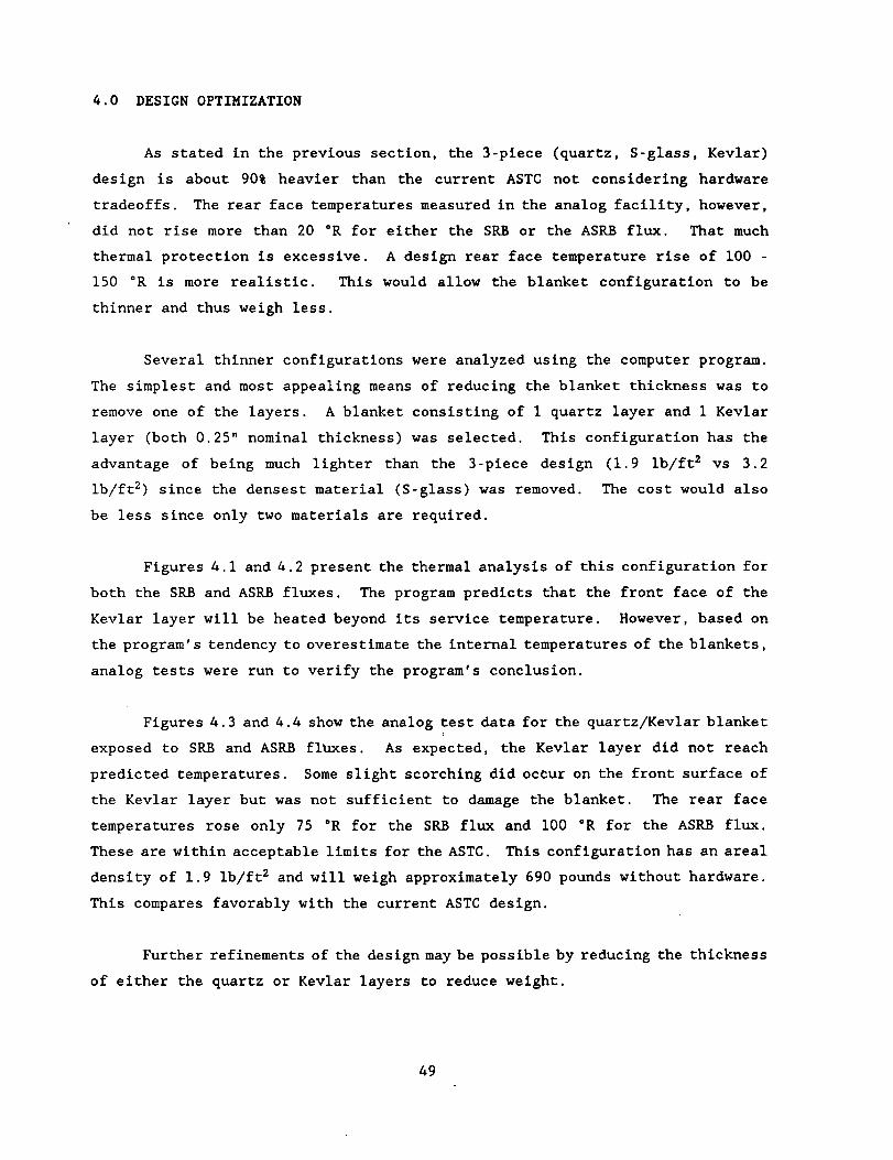
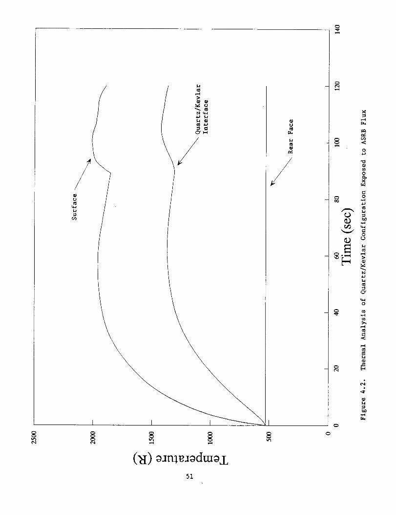
4.0 DESIGN OPTIMIZATION
As stated in the previous section, the 3-plece (quartz, S-glass, Kevlar)
design is about 90% heavier than the current ASTC not considering hardware
tradeoffs. The rear face temperatures measured in the analog facility, however,
did not rise more than 20 °R for either the SRB or the ASRB flux. That much
thermal protection is excessive. A design rear face temperature rise of i00 -
150 °R is more realistic. This would allow the blanket configuration to be
thinner and thus weigh less.
Several thinner configurations were analyzed using the computer program.
The simplest and most appealing means of reducing the blanket thickness was to
remove one of the layers. A blanket consisting of I quartz layer and i Kevlar
layer (both 0.25" nominal thickness) was selected. This configuration has the
advantage of being much lighter than the 3-piece design (1.9 Ib/ft 2 vs 3.2
ib/ft 2) since the densest material (S-glass) was removed. The cost would also
be less since only two materials are required.
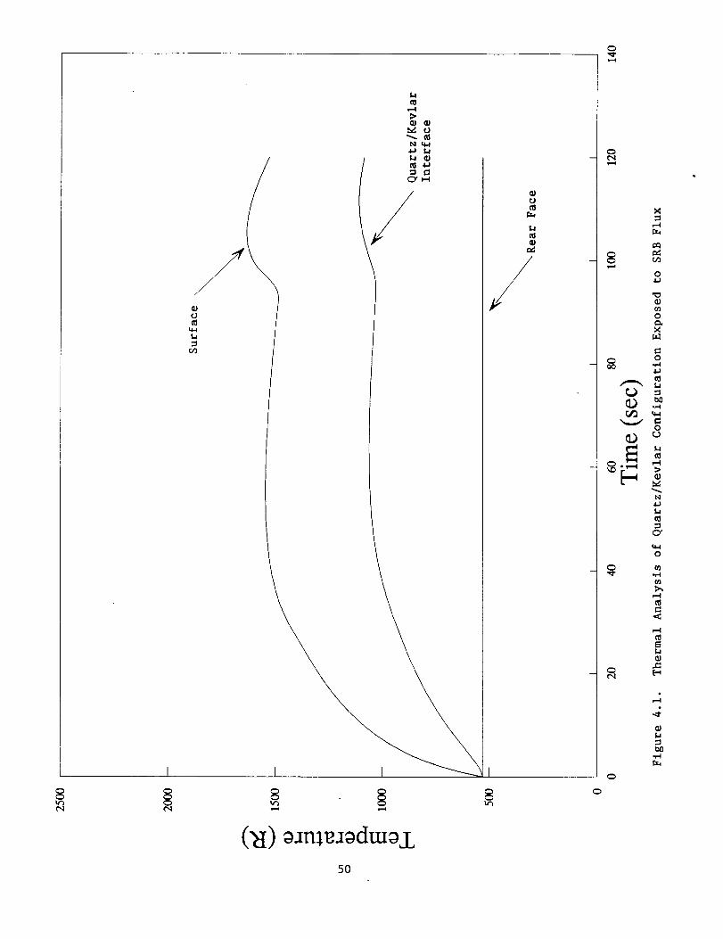
Figures 4.1 and 4.2 present the thermal analysis of this configuration for
both the SRB and ASRB fluxes. The program predicts that the front face of the
Kevlar layer will be heated beyond its service temperature. However, based on
the program's tendency to overestimate the internal temperatures of the blankets,
analog tests were run to verify the program's conclusion.
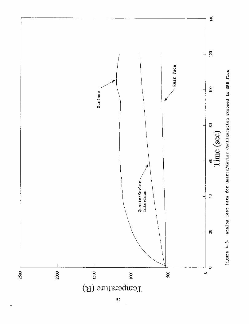
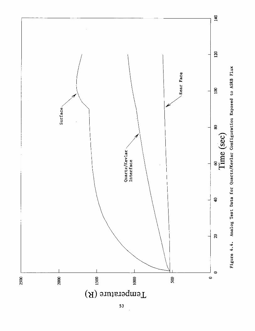
Figures 4.3 and 4.4 show the analog test data for the quartz/Kevlar blanketE
exposed to SRB and ASRB flUxes. As expected, the Kevlar layer did not reach
predicted temperatures. Some slight scorching did octur on the front surface of
the Kevlar layer but was not sufficient to damage the blanket. The rear face
temperatures rose only 75 °R for the SRB flux and i00 °R for the ASRB flux.
These are within acceptable limits for the ASTC. This configuration has an areal
density of 1.9 Ib/ft 2 and will weigh approximately 690 pounds without hardware.
This compares favorably with the current ASTC design.
Further refinements of the design may be possible by reducing the thickness
of either the quartz or Kevlar layers to reduce weight.
49

I I
(_d) _JmeJ_dm_j.,5O
0
/ -X
N
0
,-,,,4
aJ
,J=
("4
..1:_J
bO.,.,4
0
¢o0
0
¢,,J*el
0

o
u
Y
(_I)_n_dm_.L
o
Y
I
¢q
X
o
o
X
o o
o
lq
O"
u_o
t_
o
r._
51

¢.J
_J
o"J
(_I) oJn:_Jodcuoj_,
0
52

c_
tJt_
=t_
I I
c_
c_t_
,--4
oo
,._ o4.J
o
X
=o
t_t_
m _
_ u
O"
t_o
u_
[.-,
o
53

4.1 COST CONSIDERATIONS
Textile Technologies Incorporated (TTI) is the current manufacturer of the
polar weave materials evaluated in this program. TTI can weave the ASTC blanket
in a single-piece (5 feet wide on a 18 foot inner diameter). However, the 0.25"
thickness poses a major problem for the fabricator in that the number of the ends
or fiber tows that must be drawn into the loom is excessive, over 7000 ends.
This large quantity drives up the cost in the extremely large number of man-hours
required to draw the fibers into the loom. Safety and quality control also
become problematical. Therefore, TTI has suggested weaving blankets roughly one-
third the original thickness, then sewing the layers together to reach the 0.25"
thickness desired. The number of ends yarns would then be only around 2500 and
the weaving much simplified. The proposed blanket layers dimensions are 5 feet
wide, 0.065 inches thick on an 18 foot inner diameter.
This multi-ply approach will actually achieve a better thermal performance
in that there will be a greater number interfacial resistances to impede the heat
flow in the curtain. Estimated prices for the fabrics having a total thickness
of 0.25" (based upon an annual requirement of 6 ASTCs per year) are as follows:
Quartz 300 $93,000
s-2 Glass $14,800
Kevlar 29 $22,000
The proposed quartz/Kevlar configuration would cost $115,000 per ASTC.
54

5.0 CONCLUSIONS
A two-plece quartz/Kevlar (0.25" thick layers) design seems to be a
desirable configuration for a new ASTC. This configuration weighs about the same
as the current design, provides adequate thermal protection, and can be
constructed as a single piece thus greatly simplifying installation.
Some further weight reduction may be gained by further reducing the thick-
ness of the layers and allowing the rear face temperature to increase more,
although the screening process may need to be fine-tuned. Several options are
available for further refinement of the screening process. The computer program
can be modified to accept interfacial resistance inputs. The analog test setup
can include additional thermocouples to determine the interfacial resistances
actually present. A finite element model can be built to better analyze the
thermal performance of the candidate configurations. Finally, new blanket
thickness can be woven for evaluation in the analog test facility.
55

REFERENCES
,
.
.
.
5.
Touloukian, et. al., "Thermophysical Properties of Matter" Volume 2 and
Volume 5, IFl/Plenum, New York, 1973.
Incropera, DeWitt, "Fundamentals of Heat and Mass Transfer", 3rd. ed.,
John Wiley & Sons, New York, 1990.
O'Neil, "Advanced Engineering Mathematics H , 3rd. ed., Wadsworth,
California, 1991.
NASA/MSFC, "SRB Thermal Design Databook" Rev. D., September 1987.
United Technologies/USBl, "AFT Skirt Thermal Curtain", June 1987.
Report to NASA/MSFC, Contract NASS-36300.
56

LIST OFAPPENDICES
A THERMALCONDUCTIVITYMEASUREMENTTECHNIQUES
B DATAMEASUREDIN ASTMC177GUARDEDHOTPLATEAPPARTUS
C DIRECTIONALREFLECTANCEMEASUREMENTSOFPOLARWEAVEQUARTZFABRIC
D THERMALANALYSISCOMPUTERPROGRAMSOURCECODE
57


APPENDIXA
THERMALCONDUCTIVITYMEASUREMENTTECHNIQUES

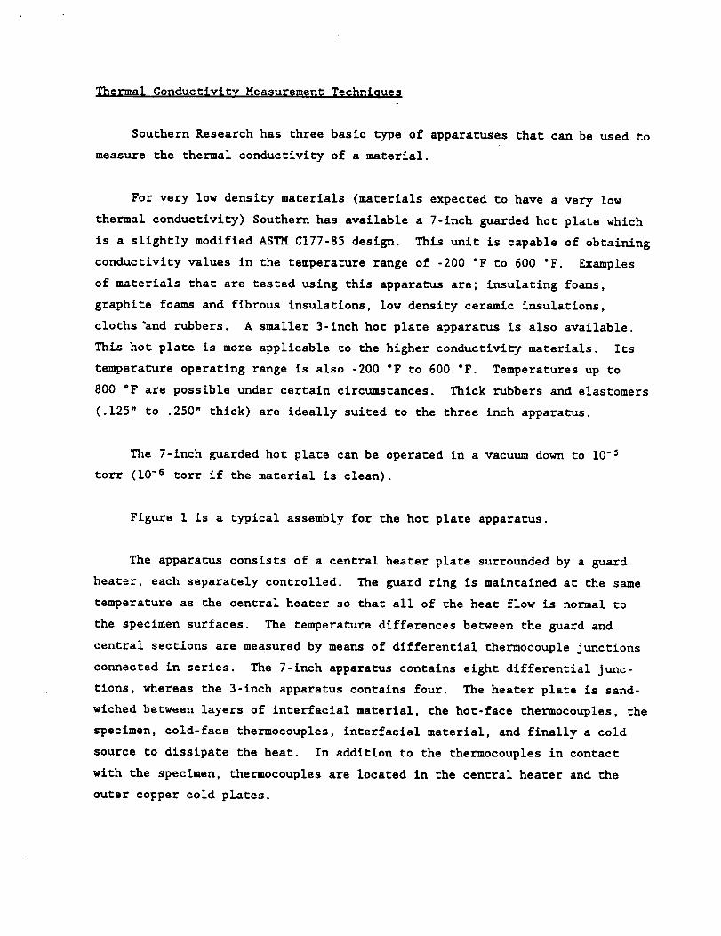
Thermal Conductivity Measurement Technicues
Southern Research has three basic type of apparatuses that can be used to
measure the thermal conductivity of a material.
For very low density materials (materials expected to have a very low
thermal conductivity) Southern has available a 7-inch guarded hot plate which
is a slightly modified ASTM C177-85 design. This unit is capable of obtaining
conductivity values in the temperature range of -200 °F to 600 "F. Examples
of materials that are tested using this apparat_s are; insulating foams,
graphite foams and fibrous insulations, low density ceramic insulations,
cloths_nd rubbers. A smaller 3-inch hot plate apparatus is also available.
This hot plate is more applicable to the higher conductivity materials. Its
temperature operating range is also -200 "F to 600 °F. Temperatures up to
800 °F are possible under certain circumstances. Thick rubbers and elastomers
(.125" to .250" thick) are ideally suited to the three inch apparatus.
The 7-inch guarded hot plate can be operated in a vacuum down to 10 -2
tort (I0 -e tort if the material is clean).
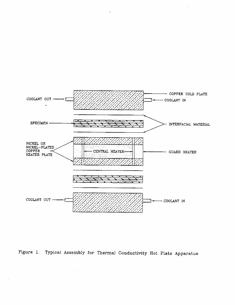
Figure 1 is a typical assembly for the hot plate apparatus.
The apparatus consists of a central heater plate surrounded by a guard
heater, each separately controlled. The guard ring is maintained at the same
temperature as the central heater so that all of the heat flow is normal to
the specimen surfaces. The temperature differences betnceen the guard and
central sections are measured by means of differential thermocouple junctions
connected in series. The 7-1nch apparatus contains eight differential junc-
tions, whereas the 3-1nch apparatus contains four. The heater plate is sand-
wiched betnveen layers of interfacial material, the hot-face thermocouples, the
specimen, cold-face thermocouples, interfacial material, and finally a cold
source to dissipate the heat. In addition to the thermocouples in contact
with the specimen, thermocouples are located in the central heater and the
outer copper cold plates.

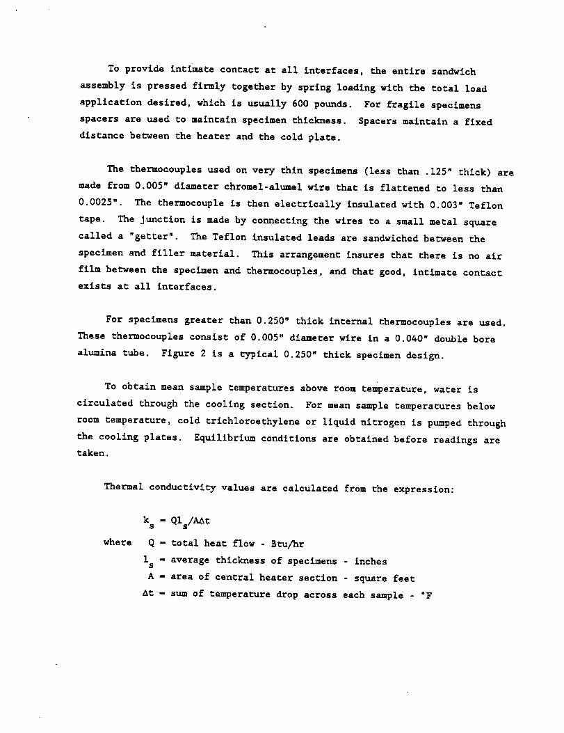
To provide intimate contact at all interfaces, the entire sandwich
assembly is pressed firmly together by spring loading with the total load
application desired, which is usually 600 pounds. For fragile specimens
spacers are used to maintain specimen thickness. Spacers maintain a fixed
distance between the heater and the cold plate.
The thermocouples used on very thin specimens (less than .125" thick) are
made from 0.005" diameter chromel-alumel wire that is flattened to less than
0.0025" The thermocouple is then electrically insulated with 0.003" Teflon
tape. The junction is made by connecting the wires to a small metal square
called a "getter". The Teflon insulated leads are sandwiched between the
specimen and filler material. This arrangement insures that there is no air
film between the specimen and thermocouples, and that good, intimate contact
exists at all interfaces.
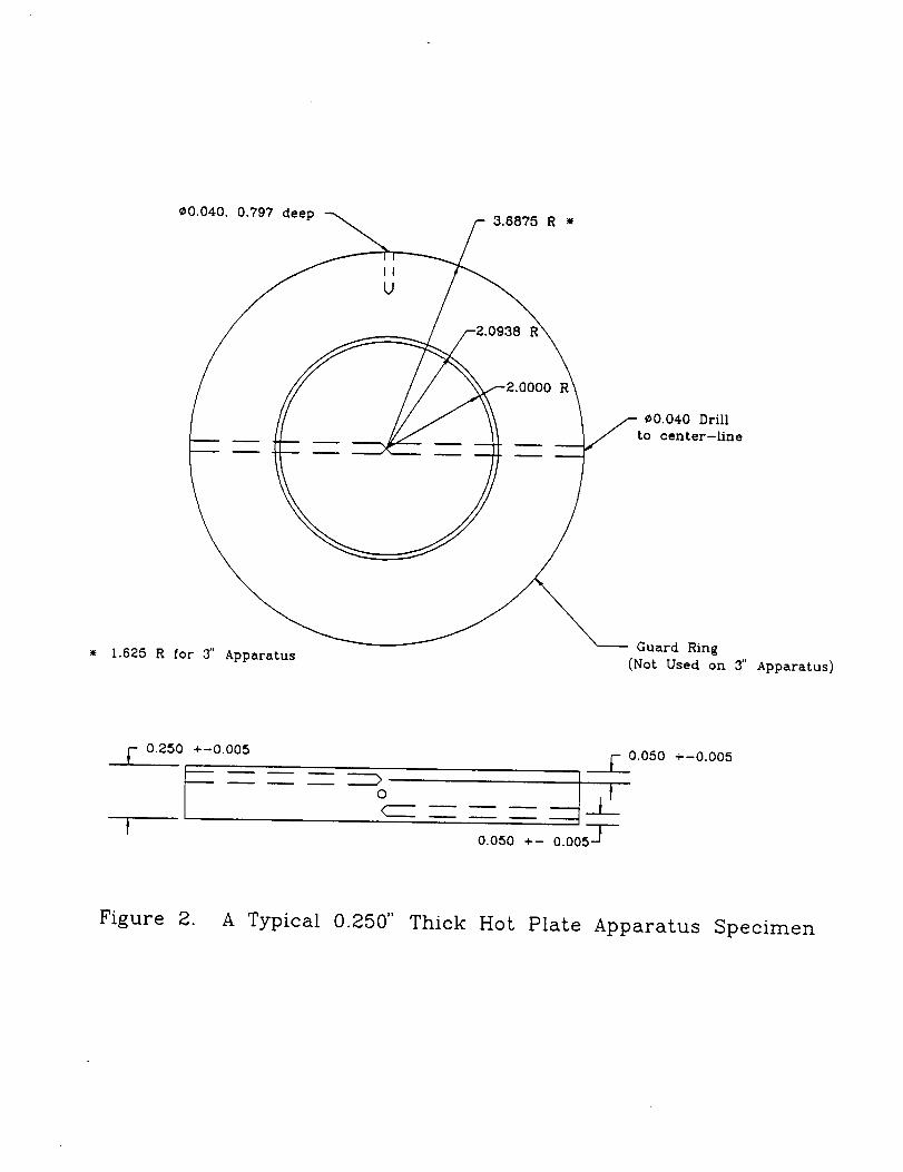
For specimens greater than 0.250" thick internal thermocouples are used.
These thermocouples consist of 0.005" diameter wire in a 0.040" double bore
alumina tube. Figure 2 is a typical 0.250" _hick specimen design.
To obtain mean sample temperatures above room temperature, water is
circulated through the cooling section. For mean sample _empera_ures below
room temperature, cold _richloroethylene or liquid nitrogen is pumped through
the cooling plates. Equilibrium conditions are obtained before readings are
taken.
Thermal conductivity values are calculated from the expression:
where
k s - QIs/AAt
Q - total heat flow - Btu/hr
1 - average thickness of specimens inchess
A - area of central heater section - square feet
At - sum of temperature drop across each sample - "F

Theoretically, Q, the heat input, should split, with exactly half of the
input flowing through each sample. The temperature drops indicate that this
condition rarely exists. Instead, there is a slight unbalance in the heat
flow. The above formula then permits a calculation of the arithmetic average
for the two panels. In this calculation the temperatures are measured
directly at the faces of the specimen by the "getters", resulting in a direct
method.
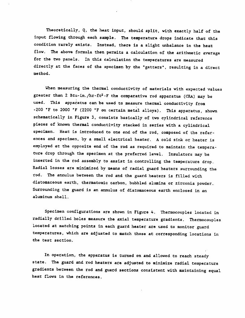
When measuring the thermal conductivity of materials with expected values
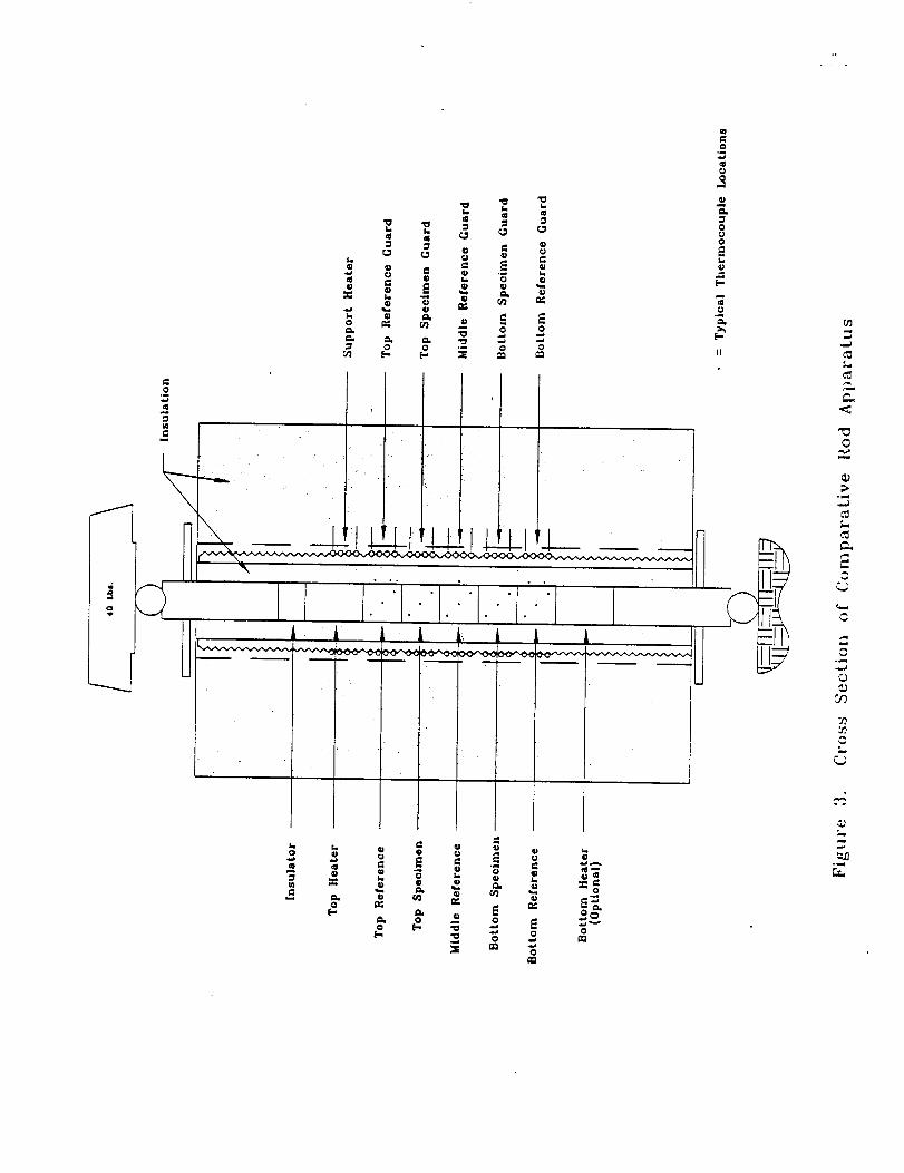
greater than 2 Btu-in./hr-ft2-F the comparative rod apparatus (CRA) may be
used. This apparat-us can be used to measure thermal conductivity from
-200 "F to 2000 "F (2200 "F on certain metal alloys). This apparatus, shown
schematically in Figure 3, consists basically of two cylindrical reference
pieces of known thermal conductivity stacked in series with a cylindrical
specimen. Heat is introduced to one end of the rod, composed of the refer-
ences and specimen, by a small electrical heater. A cold sink or heater is
employed at the opposite end of the rod as required to maintain the tempera-
ture drop through the specimen at the preferred level. Insulators may be
inserted in the rod assembly to assist in controlling the temperature drop.
Radial losses are minimized by means of radial guard heaters surrounding the
rod. The annulus between _he rod and the guard heaters is filled with
diatomaceous earth, thermatomlc carbon, bubbled alumina or zirconia powder.
Surrounding the guard is an annulus of diatomaceous earth enclosed in an
aluminum shell.
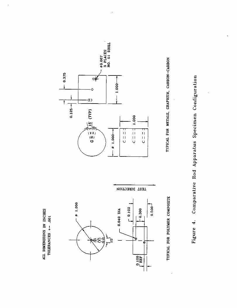
Specimen configurations are shown in Figure 4. Thermocouples located in
radially drilled holes measure the axial temperature gradients. Thermocouples
located at matching points in each guard heater are used to monitor guard
temperatures, which are adjusted to match those at corresponding locations in
the test section.
In operation, the apparatus is _urned on and allowed to reach steady
state. The guard and rod heaters are adjusted to minimize radial temperature
gradients between the rod and guard sections consistent with maintaining equal
heat flows in the references.

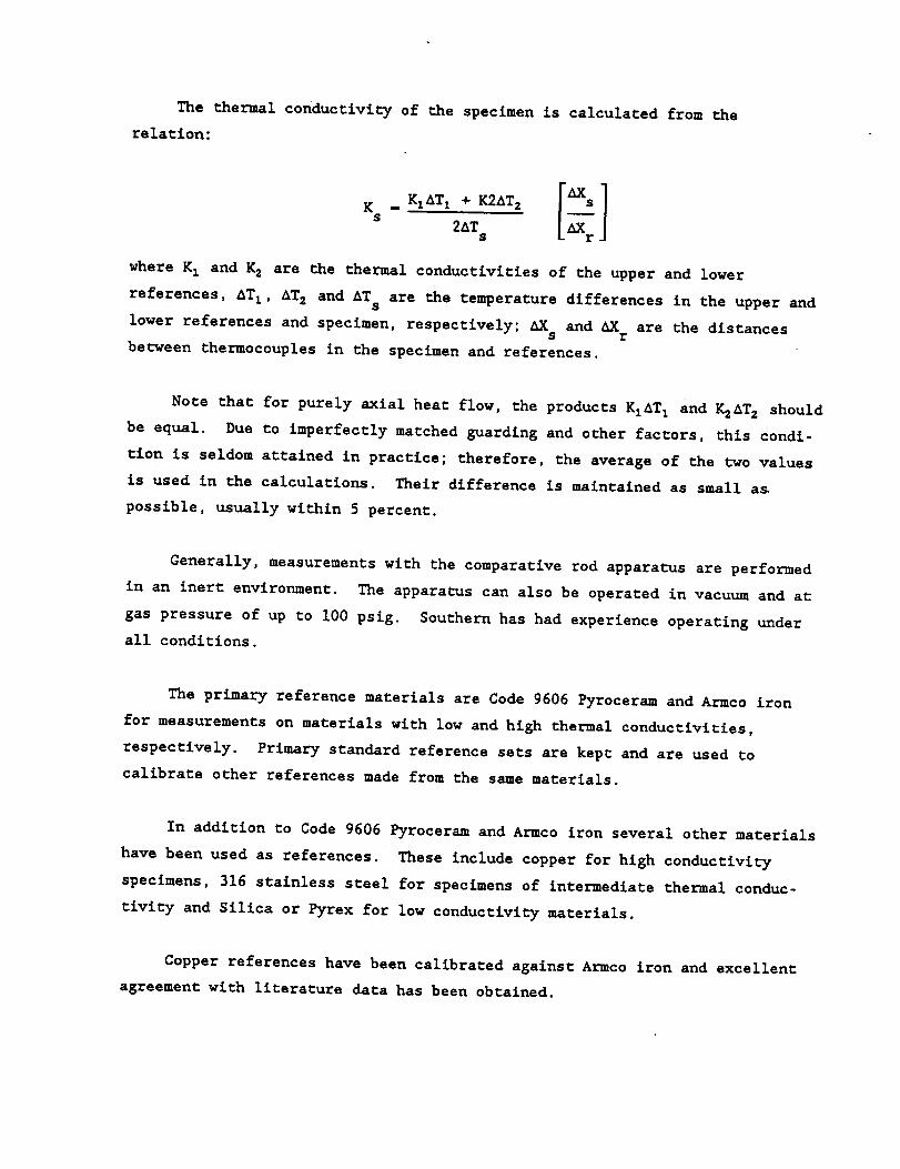
The thermal conductivity of the specimen is calculated from the
relation:
Ks
where K I and K2 are the thermal conductlviCies of the upper and lower
references, ATI, AT 2 and AT s are the temperature differences in the upper and
lower references and specimen, respectively; AX and AX are the distancess r
beUween thermocouples in the specimen and references.
Note that for purely axial heat flow, the products KIAT I and _AT z should
be equal. Due to imperfectly matched guarding and other factors, this condi-
tlon is seldom attained in practice; therefore, the average of the t_o values
is used in the calculations. Their difference is maintained as small a_
possible, usually within 5 percent.
Generally, measurements with the comparative rod apparatus are performed
in an inern environment. The apparatus can also be operated in vacuum and at
gas pressure of up to i00 psig. Southern has had experience operating under
all conditions.
The primary reference materials are Code 9606 Pyroceram and Armco iron
for measurements on materials with low and high thermal conduc_ivitles,
respectively. Primary standard reference sets are kept and are used to
calibrate other references made from the same materials.
In addition co Code 9606 Pyroceram and Armco iron several other materials
have been used as references. These include copper for high conductivity
specimens, 316 stainless steel for specimens of intermediate thermal conduc-
tlvlt-y and Silica or Pyrex for low conductivity materials.
Copper references have been calibrated against Armco iron and excellent
agreement with literature data has been obCalned.

Calibrations indicate that for materials with moderate to high thermal
conductivities the apparatus operates with a precision of about ±5 percent at
temperatures above 0 "F. Below 0 "F, the precision achieved to date has been
about ±7 percent with a total uncertainty of about ±i0 percent.
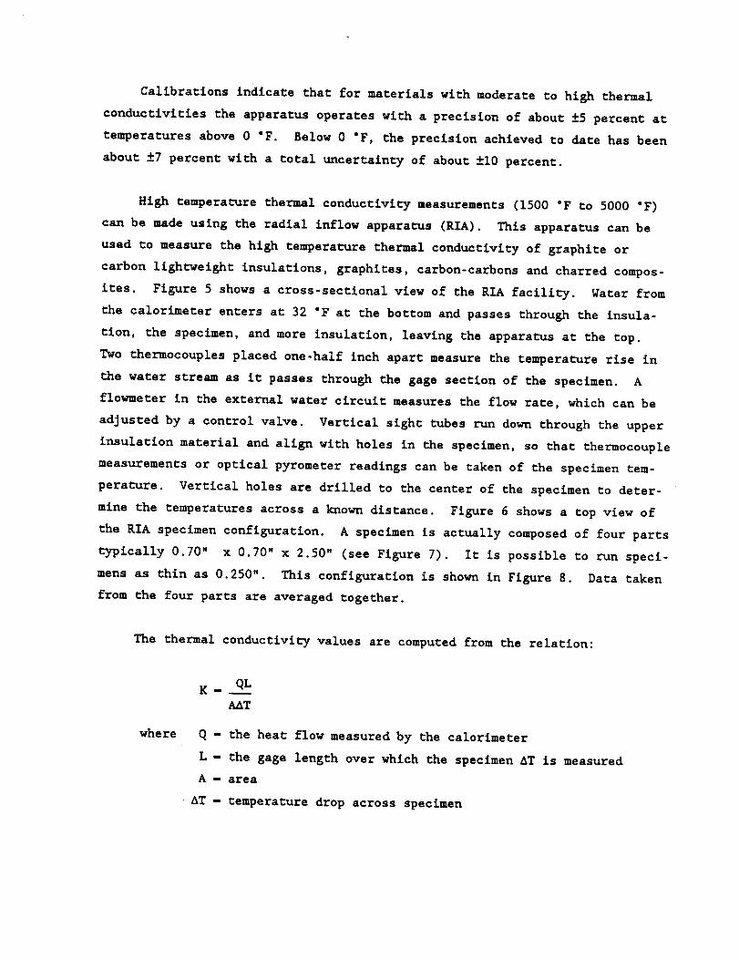
High temperature thermal conductivity measurements (1500 "F to 5000 "F)
can be made using the radial inflow apparatus (RIA). This apparatus can be
used to measure the high temperature thermal conductivity of graphite or
carbon llght-weight insulations, graphites, carbon-carbons and charred compos-
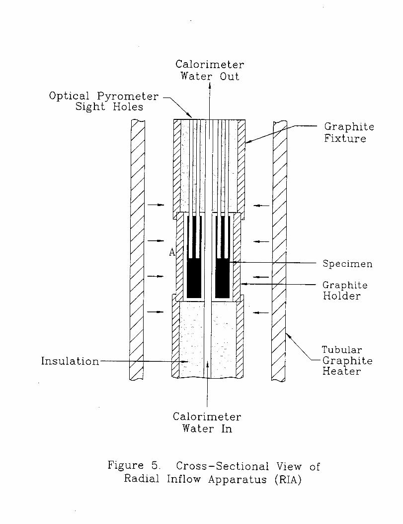
ites. Figure 5 shows a cross-sectlonal view of the RIA facility. Water from
the calorimeter enters at 32 "F at the bottom and passes through the insula-
tion, the specimen, and more insulation, leaving the apparatus at the top.
Two thermocouples placed one-half inch apart measure the temperature rise in
the water stream as it passes through the gage section of the specimen. A
flowmeter in the external water circuit measures the flow rate, which can be
adjusted by a control valve. Vertical sight tubes run down through the upper
insulation material and align with holes in the specimen, so that thermocouple
measurements or optical pyrometer readings can be taken of the specimen tem-
perature. Vertical holes are drilled to the center of the specimen to deter-
mine the temperatures across a known distance. Figure 6 shows a top view of
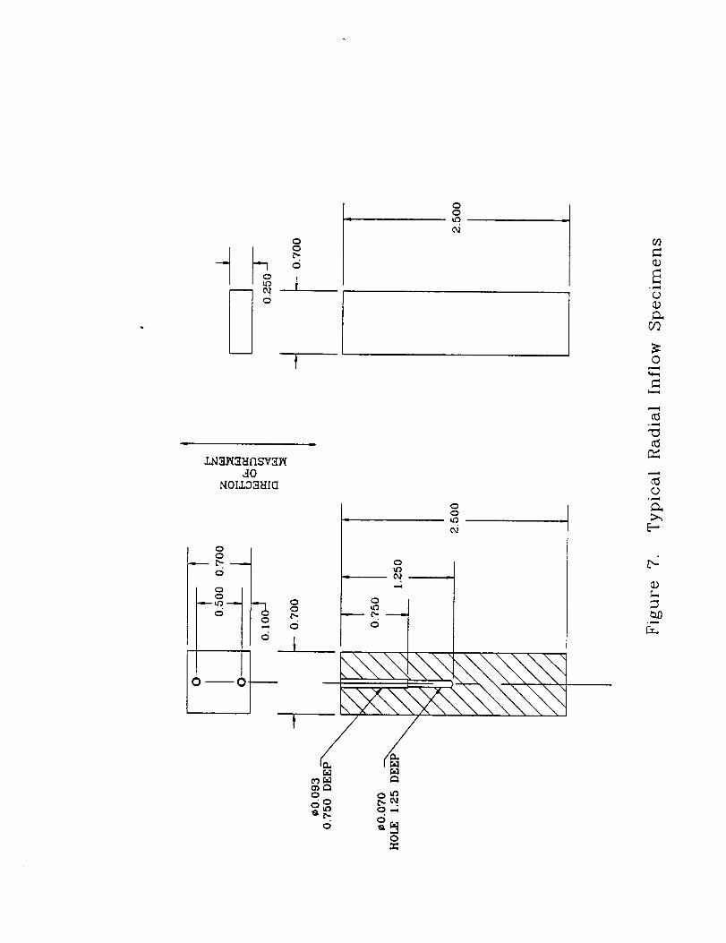
the RIA specimen configuration. A specimen is actually composed of four parts
typically 0.70" x 0.70" x 2.50" (see Figure 7). It is possible to run speci-
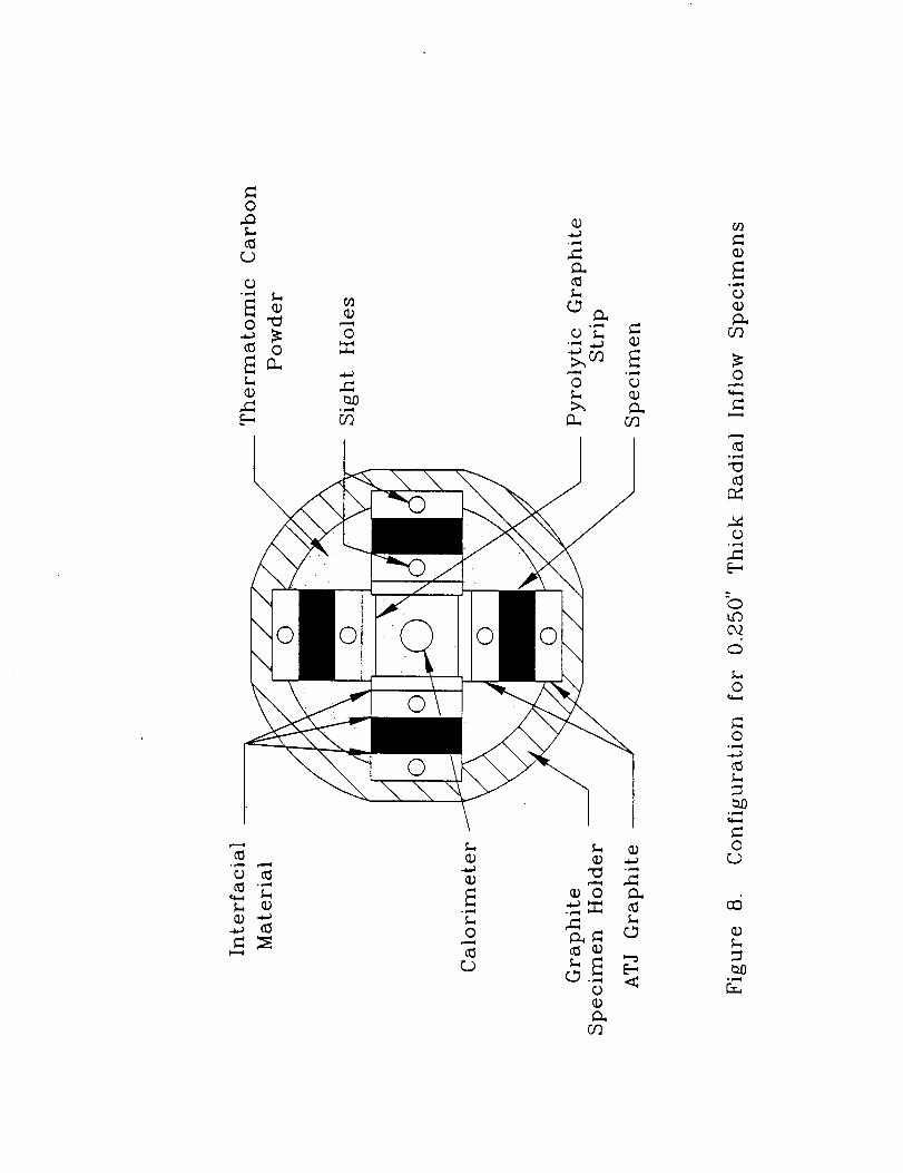
mens as thin as 0.250". This configuration is shown in Figure 8. Data taken
from the four parts are averaged together.
The thermal conductivity values are computed from the relation:
where
K- QL
AnT
Q - the heat flow measured by the calorimeter
L - the gage length over which the specimen AT is measured
A - area
• AT - temperature drop across specimen


Based on an extensive error analysis and calibrations on homogeneous
isotropic materials of known thermal conductivities, such as Armco iron and
ATJ graphite, r_e precision (coefficient of variation) in the measurements has
been established at ±7 percent over r_e temperature range of 1500 "F to
5000 "F

COOLANT OUT --'-'-- _ /_'/_/" _'/z_/JzX'_/ / // // / // / /_ // /Z/Z'X. ,, ,,, ,, J'.Z,,P_"'"""'" "" "./,S',
COPPER COLD PLATE
COOLANT IN
SPECIMEN INTERFACIAL MATERIAL
_//s // // /" // // /" // // /" //
NICKEL-PLATED _
i : _i-iii >}Z-IZIII-.i"ii'
_,,._' /// /,," / ,///z/ ,/
GUARD HEATER
COOLANT IN
Figure I. Typical Assembly for Thermal Conductivity Hot Plate Apparatus

_,0.040. 0.797 deep3.6875 R
II
U
¢0.040 Drill
to center-line
1.625 R for 3" ApparatusGuard Ring
(Not Used on 3" Apparatus)
0.250 +-0.005
0.050 +- 0.005 J
Figure 2. A Typical 0.250" Thick Hot Plate Apparatus Specimen

I,_. A _
1_, 02
0 e_ r_ _ _*._
.._ 0
o_
e-
@°_
@
¢0

=
Z o,-,. o
Z,-, I
+
Z
Z
o
t-T--
ml
o
0
A
E-I
--2oo
II II I1
II II II
II II II
U U U
MOLL33HI_ .r.S3_
o
o .< o
- _ -. g
i
Or.If
or.._
Z0
r_i
o
=
.<
e_eQ
..<
[-.,
0
0
>.,
0
° _,,=1
0
_U0"1
.,<
0
0

Optical PyrometerSight Holes
Insulation
7-////////////////I
/
/
/
//1
Calorimeter
Water Out
A
r--
J////,////,/
/
///////
GraphiteFixture
Specimen
GraphiteHolder
Tubular
GraphiteHeater
Calorimeter
Water In
Figure 5. Cross-Sectional View of
Radial Inflow Apparatus (RIA)

©
0
©
©
© C
0°_._
o_°_
0
0
OD
0
U]
0o
<
0
0
°_.._
>
0
°_

Q
00
d
ooLo
02
,_0t,/OIJ,S3_IIU
oo
Q
"- _' -"o _o
0
0 _ 0 _---
ou_
oLo
00
oo
c_
eOF,_
0c_o
_o
d
/
OLO
0*5
0
0
C_
b-,
. ,..._

o,.Q
C)
0
o '_
0
©
(D "_
0
E
o
•_ _ (D
_cn E0
o°r_q
b-,
0
0"]
0
O_
0
0
[-..
o
Cx2
0
o
0
0
_5
o_,,I


APPENDIX B
DATA MEASURED IN ASTM C177 GUARDED HOT PLATE APPARATUS

c_
_J
o
"0
"0
,--4
(/3
C
u_
N
m
00
_J
0
_J
0
o_J
o q-i .,.-t
_q-4
o, °o
• _:_m O_
,_.,4_Z_ ..._0
o
0_
o
0
o_
o
(J
,--4
!
_ID •
_u'_
°° °°
0_._
_q
o
p_
o
p_

C'4
Q;,..-I
,U
o,
a)4-_
.l.Jo
Q)
m
r,.3
r_
m
mm
!r._
O0
,.-4
Q;
,C
q-eo
p,.,,_u
p,
.l.J0
"o
0
o
_ 0
1.1
E-I 0
_ o, oo
r.; m
0 o', o',, _ 0_ ',.o 0 e-I ,-I
o_, -,t" -,1" o_ ..,1"0 co o.4 (_ u_ u'_
0
!
0
0
0
0
r_
, Ci=l
i
., ,0
0Z_
m
0
u_ cO

,-4
.JJ
CO0,
eO,.4D.I
0
e_
r'_
i....4
Q)
_Jf--I
00
,o
J....I
f--IbO
0
.,-I,00
0
r.4el
0
!
0
0
_.....J_,...I!
°o oo
0
O
0
%
!
,o oo
_o_
0
_4 _4

E_
m
C3_
t-4
0
"0
r_i.-I
Z
N
o
o
4-)
o
o
• _ Cu
r._ o
<_ _ I_o
0
.1-1 <','1
_ •
_ oo °o
o m
r_._
oo f_.c,4od
r,_
0
c_ o_
o u_
i_.i-_ r_r'_ i_.
c,d
u-1 u_

0
I_,,-4
r_
Z
,-4o
0
i-40
0
"C_ •
0
,.,-I _ 4-)
O I1-1 ,.,_
_ <_ I_o
!
_,¢10
,gl
I_ o
r_
m_
_ _O
_ _O
O
°.
.,..4
_D t_
OOcN _'N
,,-gO
O_..I
_4_4
u'3

_0
q)
E_
m
c_
a)
,-i
o
"0
c_
r-..
c.3
r.n,<
cncO
v
c_
_J
c_
0
0
,1-1:>
4.J0
O
0 _ ,t-I_.3 0
_::_ _,_ _._
m
oo oo
El O_
U m
u'3 _
0
_ C4QO
r_ P_
O0


APPENDIX C
DIRECTIONAL REFLECTANCE MEASUREMENTS OF POLAR WEAVE QUARTZ FABRIC
REPORT BY:
SURFACE OPTICS CORPORATION

SOC.R731-001.0692
DIRECTIONAL REFLECTANCEMEASUREMENTS
ON ONE (1) SAMPLE OFPW QUARTZ FABRIC
FINAL REPORTAND
APPENDIX A
Prepared for:
SOUTHERN RESEARCH INSTITUTE
Birmingham, Alabama 35205
Prepared under:
PURCHASE ORDER NUMBER BH-33087
JUNE 1992
SURFACE OPTICSCORPORATION
P.O. Box 261602
San Diego, CA 92196TEL: (619) 578-8910FAX_ (619) 578-0484

SOC-R731-001-0692
DIRECTIONAL REFLECTANCE MEASUREMENTS
ON ONE (1) SAMPLE OF
PW QUARTZ FABRIC
FINAL REPORT
AND
APPENDIX A
Prepared for:.
SOUTHERN RESEARCH INSTITUTE
Birmingham, Alabama 35205
Prepared under:.
PURCHASE ORDER NUMBER BH-33087
JUNE 1992

TABLE OF CONTENTS
SECTION PAGE
1.0 INTRODUCTION ............................................... 1
2.0 SAMPLE DESCRIPTIONS AND _UREMENTS REQUIRED ........ 1
3.0 DEFINITIONS AND NOMENCLATURE ............................ 1
3.1 Symbols and Units ......................................... 1
3.2 CoordinateSystem and Sign Convention ........................ 1
3.3 PolarizationConvention ..................................... 4
4.0 REFLECTANCE PROPERTIES ................................... 6
4.1 Directional Reflectance ...................................... 6
4.2 Quantities Derived from Directional Reflectance ................... 7
4.2.1 Emittance ........................................ 7
4.2.2 Solar Absorptance .................................. 9
5.0 APPARATUS AND INSTRUMENTATION .......................... 10
5.1 Directional Reflectometry ................................... 10
5.1.1 Cary-Integrating Sphere Reflectometer ................. 10
5.1.2 Infrared Ellipsoidal Reflectometer ..................... 12
5.1.3 Instrumentation Polarization ......................... 17
5.1.4 Norma] (0, - 0 °) and Grazing Incidence Measurements ..... 17
5.1_5 Performance Verification ............................ 18
5.1.5.1 Cary-Sphere ............................. 19
5.1.5.2 Ellipsoidal Reflectometer ................... 19
6.0 DATA REDUCTION AND PRESENTATION ........................ 21
6.1 Codes for Data Reduction ................................... 21
6.1.1 Directional Reflectance Codes ........................ 21
6.2 Data Presentation ........................................ 22
TABLE OF APPENDICES
APPENDIX
A
PAGE
Southern Research Institute:PW Quartz Fabric,SurfaceOpticsCorporationSample Number FS5675 ............................... A-1
LIST OF FIGURES
FIGURE
1
2
3
4
5
6
7
8
9
PAGE
Coordinate System for Reflectometry Measurements ..................... 4
Definition of Striae Orientation ..................................... 5
Convention Describing the Polarization of Reflected Light ................. 6
Diagram Illustrating Concept of Directional Reflectance ................... 6
Schematic of Cary-Integrating Sphere Reflectometer .................... 11
Schematic of Infrared Reflectometer ................................. 15
Directional Reflectance of Fused Silica Standard at 16 _m - Perpendicular(±), Parallel ( I I ), and Average ..................................... 20
Directional Reflectance Data Processing for Thermal AnalysisCalculations ................................................... 23
Directional Reflectance Data Processing for Signature Calculations ......... 24
±±
LIST OF TABLES
TABLE PAGE
1
2
3
4
Sample Descriptionand Test Parameters .............................. 2
Symbols and Units ............................................... 3
Cary-IntegratingSphere Reflectometer............................... 13
InfraredReflectometer ........................................... 14
iii

This pageintentionally left blank.
iv
SUMMARY
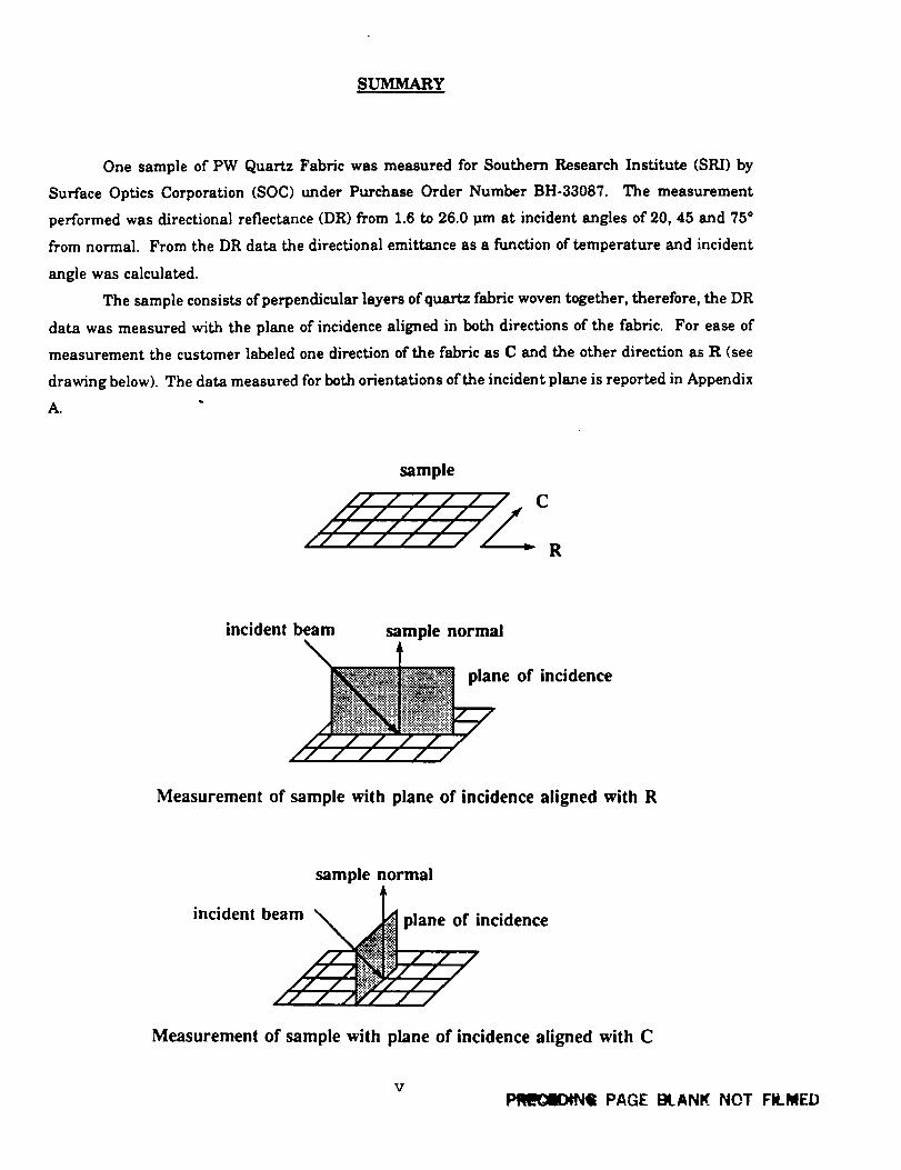
One sample of PW Quartz Fabricwas measured for Southern Research Institute(SRI)by
Surface Optics Corporation(SOC) under Purchase Order Number BH-33087. The measurement
performed was directionalreflectance(DR) from 1.6to 26.0_m at incidentanglesof20, 45 and 75°
from normal. From the DR data the directionalemittanceas a functionoftemperature and incident
angle was calculated.
The sample consistsofperpendicularlayersofquartzfabricwoven together,therefore,the DR
data was measured with the plane ofincidencealignedin both directionsof the fabric.For ease of
measurement the customer labeledone directionofthe fabricas C and the otherdirectionas R (see
drawing below).The datameasured forbothorientationsoftheincidentplane isreportedinAppendix
A.
sample
C
R
incident beam sample normal
e of incidence
Measurement of sample with plane of incidence aligned with R
sample normal
incident beam \
// / _/
,._plane of incidence
_ / / /9///
"////
Measurement of sample with plane of incidence aligned with C
VP_L_llOtNili PAGE BLANK NOT FILMED

This page intentionallyleftblank.
v±
1.__0 INTRODUCTION
This reportpresents directionalreflectancedata on one (1) sample material provided by
Southern Research Institute.The work was performed under Purchase Order Number BJ-33087.
2.____0SAMPLE DESCRIPTIONS AND MEASUREMENTS REQUIRED
Table I isan overview ofallsamples and ofthe opticalmeasurements performed.
3.____0DEFINITIONS AND NOMENCLATURE
3.1 S.ymbols and Units
Table 2 containsa listingofthe symbols and unitsofquantitiesused in thisinvestigation.
3.2 Coordinate System and Sign Convention
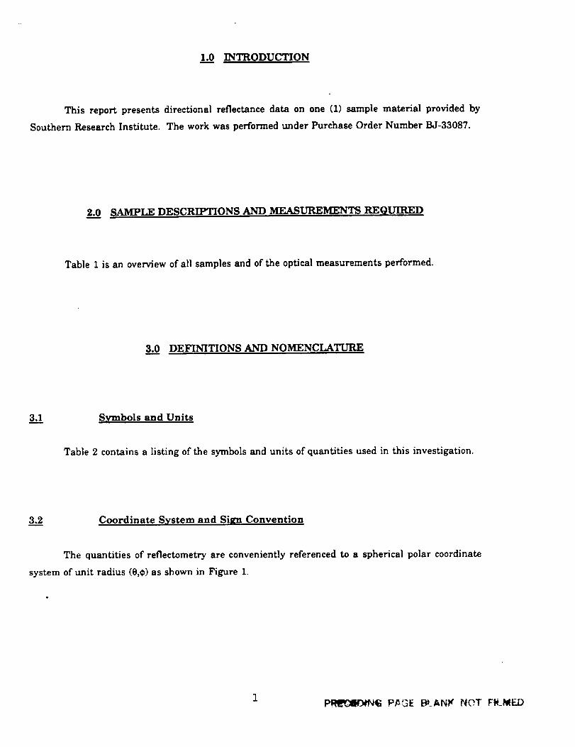
The quantitiesof reflectometryare convenientlyreferencedto a sphericalpolar coordinate
system ofunitradius (e,¢)as shown in Figure 1.
IP__ P_E E_.ANK NOT FI__I_IED

Table 1
Sample Description and Test ParametersSouthern ReseArch Institute
ERASFORMAT
BASICNUMBER
MATERIALDF_CRHYFION
DIRECTIONAL
REFLECTANCE
O i= 20,45and 75"
@i = C and R (seedrawing)
1.6 - 26.0 pin
FS5675 PW Quartz X
back of sample
R
C
2

Table 2
Symbols and Units
SYMBOL UNITS
BDR
DR
J_
N,
N,
n
k
a
_d
e,
g,
II
±
Pd
s
q),
T
do_,
dco,
h
C
k
= BidirectionalReflectance
= DirectionalReflectance
= Johnson'sSolarIrradianceFunction
= Source Radiance
= ReflectedRadiance
= RefractiveIndex
= ExtinctionCoemcient
= Solar Absorptivity
= SpectralDirectionalEmittance
= IncidentPolarAngle
-- ReflectedPolar Angle
= Wavelength
= Lower Value ofWavelength
= Upper Value ofWavelength
= ParallelPolarizedLight
= PerpendicularPolarizedLight
= DirectionalReflectanceofan
Unpolarized IncidentBeam
= DirectionalReflectanceUncorrectedforInstrumentation Polarization
= BidirectionalReflectance
= IncidentAzimuth Angle
= ReflectedAzimuth Angle
= Temperature
= Source SolidAngle
= ReflectedSolidAngle
= Planck'sConstant
= Speed ofLight
= Boltzman's Constant
steradians"
dimensionless
watts meter2* micrometers_
watts meterz*steradians"
watts meter"_*steradians"
dimensionless
dimensionless
dimensionless
dimensionless
degrees
degrees
micrometers
micrometers
micrometers
dimensionless
dimensionless
steradians"_
degrees
degrees
degrees
steradians
steradians
jouleosec
mesec -]
joule°kelvin_
3
+Z
+Y
Figure I. Coordinate System for Reflectometry Measurements.
The sample centercoincideswith the originofa right-handedCartesiancoordinatesystem
(x,y,z).The polar angle e is measured downward from the positivez-axis,the azimuth angle ¢
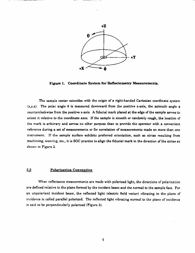
counterclockwisefrom the positivex-axis.A fiducialmark placedatthe edge ofthe sample servesto
orientitrelativetothe coordinateaxes. Ifthe sample issmooth or randomly rough,the locationof
the mark isarbitraryand servesno other purpose than to provide the operatorwith a convenient
referenceduring a setofmeasurements or forcorrelationofmeasurements made on more than one
instrument. If the sample surfaceexhibitspreferredorientation,such as striaeresultingfrom
machining, weaving, etc.,itisSOC practicetoalignthe fiducialmark inthe directionofthe striaeas
shown in Figure 2.
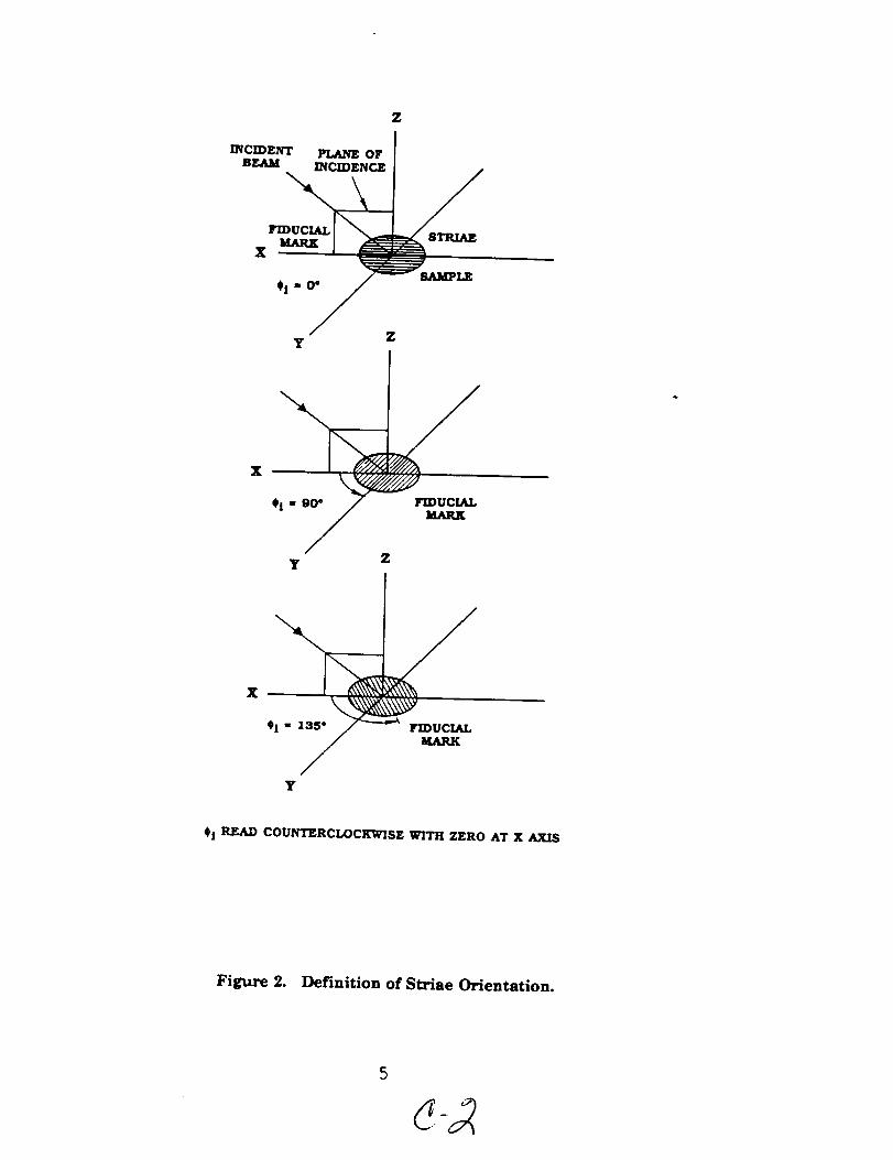
3.3 Polarization Convention
When reflectance measurements are made with polarized light, the directions of polarization
are defined relative to the plane formed by the incident beam and the normal to the sample face. For
an unpolarized incident beam, the reflected light (electric field vector) vibrating in the plane of
incidence is called parallel polarized. The reflected light vibrating normal to the plane of incidence
is said to be perpendicularly polarized (Figure 3).
4
PLANE OFINCIDENCE
Z
FIDUCIALMARK
X
#i = O°
STRIAE
SAMPLE
y Z
X
0i = 9_ FIDUCIALMARK
y Z
#! =
Y
#i READ COUNTERCLOCKWISE WITH ZERO AT X AXIS
Figure 2. Definition of Striae Orientation.
P----AKALLEL POLARIZED REFLECTED BEAM.
(Portion of reflected light vibrating panflle] tothe plane of incidence.)
_RPENDICULAR POLARIZED REFLECTED BEAM.
(Portion of Reflected light vibrating perpendicular tothe plane of incidence.)
Figure 3. Convention Describing the Polarization of Reflected Light.
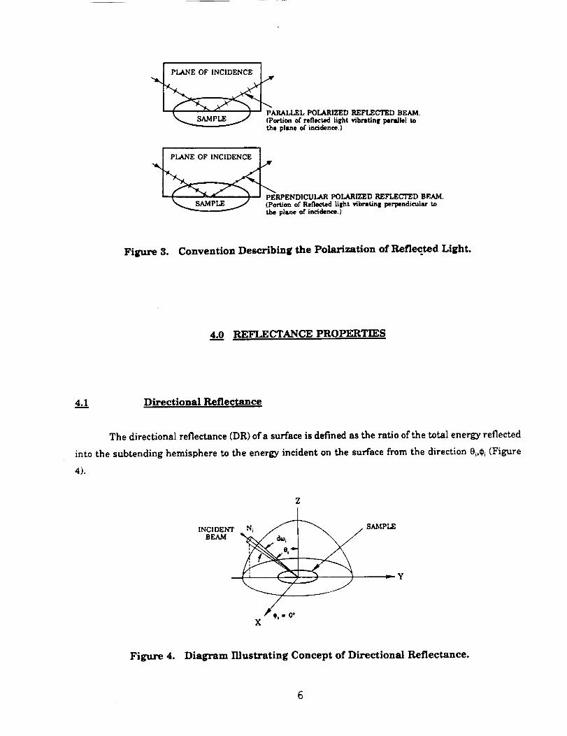
4.__0 REFI_CTKNCE PROPERTIES
4.__! Directional Reflectance
The directionalreflectance(DR) ofa surfaceisdefinedas theratioofthe totalenergy reflected
intothe subtending hemisphere to the energy incidenton the surfacefrom the direction0,,¢,(Figure
4).
Z
INCIDENT
BEAM
Y
_0i " 0°X
Figure 4. Diagram Illustrating Concept of Directional Reflectance.
Followingthe notationofNicodemus I,the directionalreflectancemay be expressedin terms
ofprimary quantitiesas
fo_" fo_'_Jr, m e, _ e, de,d.I),p._e,._,)-
N mm e, cos e t de, _j
(I)
The relationbetween directionaland bidirectionalreflectance(BDR) isgiven by the integral
ofthe latterover the viewing hemisphere
p_e,.4_,)= ./'_"J"o"_ p'(e,.d),;e,._ m e, _ e, ae, _, (2)
For a perfectlydiffuseisotropicreflector(p'(0i,_,;0,,¢,)= constant),integrationof(2)gives
Pd = _P' (3)
4.2 Quantities Derived from Directional Reflectance
The measured directionalreflectanceof a surfacemay be used to compute two important
propertiesrequiredforradiativeheat transferanalysis,viz.the directionalemittance and the solar
absorptance.
4.2.1 Emittance
By reasonsofconservationofenergy,the directionalemittanceofan opaque surfaceata given
wavelength and angle ofincidencemay be expressedby
Nicodemus, F.,"DirectionalReflectanceand Emissivityofan Opaque Surface",Applied Optics,Vol.4,No. 7 (July 1965).
e_(er4_r_.) - Z - p,.(er4¥).) . (4)
where pd((}i,@,,)_)isthe measured directionalreflectance.*From thisrelation,the totaldirectional
emittance ofthe surfaceat a given temperature may be found by
t/er4rt) - I - [o"PJ(t)e(t,7)
[o"e(t,7)dt
(5)
where
_.,7) = 8_: , (6)
isPlanck'sFunction forthe givenwavelength and temperature. Substitutingvaluesforthe constants
h,cand k and providingthe appropriateunitconversionsok can be expressedinmicrometers we have
P().,7) = 0.000119088 (7)_.s[el_zr - 1]
SOC softwarehas been developedtoprovideemittance data ofthree types,depending on the
angular coverage presentin the reflectancemeasurements:
(I) directional,near-normal emittance,when reflectancehas been measured at near-normal
incidence(9= 20°);
(2) directionalangular emittance,when reflectancehas been measured at any incidenceangle
other than near-normal;
* The O. and _, dependence of p, and (, is dropped from the notation for reasons of breviW andis assumed for the remainder of this discussion.
8
(3) total hemispherical emittance, when reflectance has been measured over a sufficiently wide
range of incidence angles to permit integration over the hemisphere (assuming no ¢
dependence for_.(e;,¢,)), viz.
z# ,, 2f; n z,(e) sine rose dB (8)
4.2.___22 Solar Absorptance
According to Kirchhofl'sLaw, the absorptanceof a surfaceat any wavelength isequal to its
emittance under equilibriumconditions
a_ - e_ (9)
The solarabsorptanceofthe surfacemay thereforebe writtenas
£3
f []- p_(X)]J(t)d(t)
aj ffi _tl
f J(_.) d(_.)
(10)
where J(;_)isthe solarirradiancefunction.The limitson the integrals(_hand _) are typically0.2pm
and 7.0pro,respectively.These limitsare chosensuch thatthe equationcan be adequatelycalculated
without significanterror.SOC program SOLARAB calculatesthe exoatmospheric solarabsorptance
ofa surfacefrom themeasured directionalreflectanceand theNASA solarspectrum SP-8005, modified
to givea solarconstantof 1368 (watts/mS).The computationalprocedure selectspointsofthe solar
irradiancefunctionwhich match the wavelengths ofthe measured reflectances,using interpolation
where necessary. The program iscapable ofutilizingdirectionalreflectancedata obtained over the
fullrange ofanglesof incidence.
9
5.____?APPARATUS AND INSTRUMENTATION
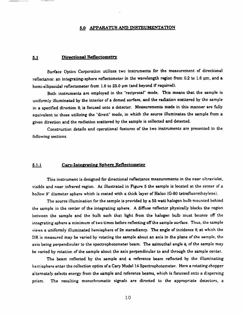
5._!1 Directional Reflectometry
Surface Optics Corporation utilizestwo instruments for the measurement of directional
reflectance:an integrating-spherereflectometerin the wavelength regionfrom 0.2 to 1.6_m, and a
hemi-ellipsoidalreflectometerfrom 1.6to25.0 tim (and beyond ifrequired).
Both instruments are employed in the "reciprocal"mode. This means that the sample is
uniformlyilluminatedby the interiorofa domed surface,and the radiationscatteredby the sample
in a specifieddirection0,isfocusedonto a detector.Measurements made in thismanner are fully
equivalentto those utilizingthe "direct"mode, in which the sourceilluminatesthe sample from a
given directionand the radiationscatteredby the sample iscollectedand detected.
Constructiondetailsand operationalfeaturesof the two instruments are presented in the
followingsections.
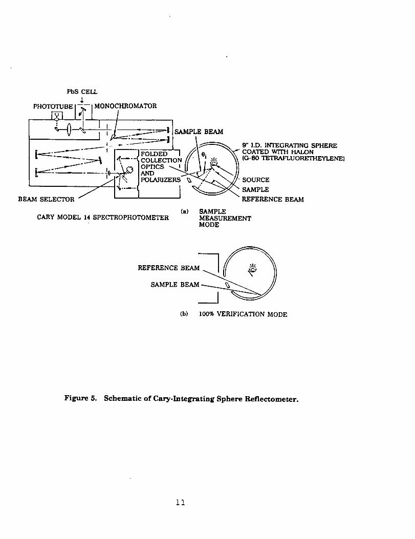
5.1.1 Cary-Integrating Sphere Reflectometer
This instrument is designed for directional reflectance measurements in the near ultraviolet,
visible and near infrared region. As illustrated in Figure 5 the sample is located at the center of a
hollow 9" diameter sphere which is coated with a thick layer of Halon (G-80 tetrafluoretheylene).
The source illumination for the sample is provided by a 55 watt halogen bulb mounted behind
the sample in the center of the integrating sphere. A diffuse reflector physically blocks the region
between the sample and the bulb such that light from the halogen bulb must bounce off the
integrating sphere a minimum of two times before reflecting offthe sample surface. Thus, the sample
views a uniformly illuminated hemisphere of 2_ steradiancy. The angle of incidence e, at which the
DR is measured may be varied by rotating the sample about an axis in the plane of the sample, the
axis being perpendicular to the spectrophotometer beam. The azimuthal angle _, of the sample may
be varied by rotation of the sample about the axis perpendicular to and through the sample center.
The beam reflected by the sample and a reference beam reflected by the illuminating
hemisphere enter the collection optics ofa Cary Model 14 Spectrophotometer. Here a rotating chopper
alternately selects energy from the sample and reference beams, which is focussed onto a dispersing
prism. The resulting monochromatic signals are directed to the appropriate detectors, a
10
PbS CELL
PHOTOTUBE 17,_--- IMONOCHROMATOR
i _ °j I, L__. __l! "_-V-- "_' , t .[-- _::=_I 18AMPI_ BEAM
8 .- ----" I [_'- 9" I.D. INTEGRATING SPHERECOATED
- :_ I_.-"--_ COLLECTION H'" _ : "_" \\ (G-80 TETRAFLUORETHEYLENE)
_:_: .... -_e--_ _" lAND "_'#;# "'_,._ Jl
i' " POLARIZERS _ ,' "SOURCE
SAMPLE
BEAM SELECTOR REFERENCE BEAM
(a) SAMPLECARY MODEL 14 SPECTROPHOTOMETER MEASUREMENT
MODE
REFERENCE BEAM l]l__SAMPLE BEAM
(b) 100% VERIFICATION MODE
Figure 5. Schematic of Cary-Integrating Sphere Reflectometer.
11
photomultipliertube forthe regionfrom 0.3to 0.8 _m, and a lead sulphidecellfor thatfrom 0.8 to
1.6_m when measuring polarizeddata. The detect_rcircuitsautomaticallyform the differenceofthe
two signalswhich isdirectlyproportions]to the directionalreflectance(DR), and which isdisplayed
as function of wavelength on a stripchartrecorder. For internalcalibration,the instrument is
operated in the 100% or verificationmode in which the two branches of the spectrophotometer
collectionopticsview the same spot on the illuminatinghemisphere. The principalfeatures,
components and performance characteristicsofthe instrument are shown inTable 3.
Measurements inthe ultraviolet(UV) areaofthe spectrum can be extended from 0.3_tm down
to 0.2tim with minor modificationsto the Cart spectrometer.To extend measurements fartherinto
the U'v',the 55 watt halogen bulb isreplacedwith a deuterium lamp thatprovidessignificantlymore
energy in the UV portion of the spectrum. In addition to replacement of the source, the
photomultipliertube is replacedwith another photomultipliertube with superiorresponse in the
ultravioletportionofthe spectrum. With thesetwo modificationsthe directionalreflectancedata can
be collecteddown to 0.2_m unpolarized.The methods describedpreviouslytocalibrateand measure
the directionalreflectanceofa materialare not affectedwith the change ofthe sourceand detector.
PolarizedUV measurements requirethat the Glan Thompson prism polarizers(- 0.3 to 1.6_m) be
replacedwith UV dichroicsheetpolarizers(0.2to 0.31pro).
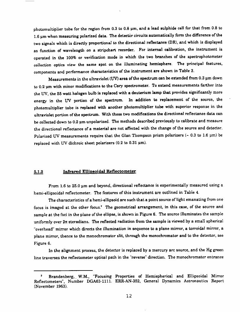
5.1.__..22 Infrared Ellipsoids] Reflectometer
From 1.6 to 25.0 tim and beyond, directional reflectance is experimentally measured using a
hemi-ellipsoidal reflectometer. The features of this instrument are outlined in Table 4.
The characteristics ofa hemi-ellipsoid are such that a point source of light emanating from one
focus is imaged at the other focus? The geometrical arrangement, in this case, of the source and
sample at the foci in the plane of the ellipse, is shown in Figure 6. The source illuminates the sample
uniformly over 2_ steradians. The reflected radiation from the sample is viewed by a small spherical
"overhead" mirror which directs the illumination in sequence to a plane mirror, a torroidal mirror, a
plane mirror, thence to the monochromator slit, through the monochromator and to the detector, see
Figure 6.
In the alignment process, the detector is replaced by a mercury arc source, and the Hg green
line traverses the reflectometer optical path in the "reverse" direction. The monochromator entrance
Brandenberg,. W.M., "Focusing
Reflectometers",Number DGA63-1111.
(November 1963).
Properties of Hemispherical and EllipsoidalMirror
ERR-AN-352, General Dynamics Astronautics Report
12
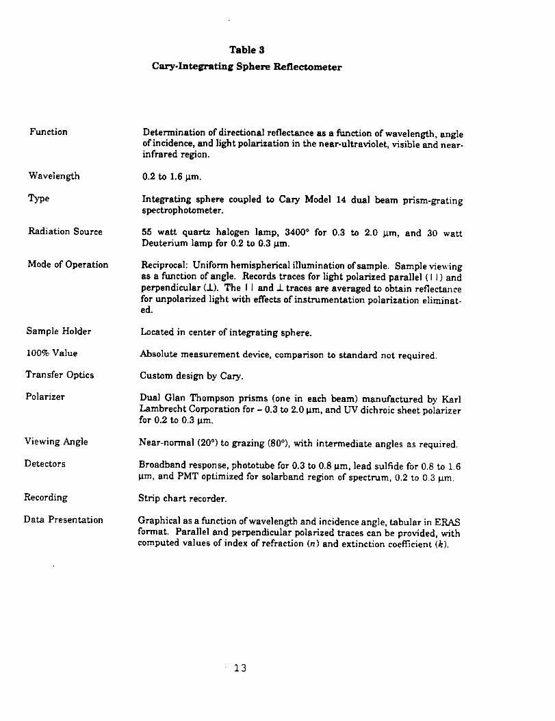
Table 3
Cary-Integrating Sphere Reflectometer
Function
Wavelength
Type
Radiation Source
Mode of Operation
Sample Holder
100% Value
Transfer Optics
Polarizer
Viewing Angle
Detectors
Recording
Data Presentation
Determination of directional reflectance as a function of wavelength, angleof incidence, and light polarization in the near-ultraviolet, visible and near-infrared region.
0.2 to 1.6 ttm.
Integrating sphere coupled to Cary Model 14 dual beam prism-gratingspectrophotometer.
55 watt quartz halogen lamp, 3400 ° for 0.3 to 2.0 _tm, and 30 wattDeuterium lamp for 0.2 to 0.3 _m.
Reciprocal:Uniform hemisphericalilluminationofsample. Sample viewing
as a functionofangle. Records tracesforlightpolarizedparallel(lJ)and
perpendicular(.l.).The Iiand J.tracesare averaged toobtainreflectance
forunpolarizedlightwith effectsofinstrumentationpolarizationeliminat-ed.
Located in centerofintegratingsphere.
Absolute measurement device,comparison to standard not required.
Custom design by Cary.
Dual Glan Thompson prisms (one in each beam) manufactured by Karl
Lambrecht Corporationfor- 0.3to2.0tim,and UV dichroicsheetpolarizerfor0.2 to 0.3tim.
Near-normal (20°)to grazing(80°),with intermediateanglesas required.
Broadband response, phototube for 0.3 to 0.8 ttm, lead sulfide for 0.8 to 1.6
tLm, and PMT optimized for solarband region of spectrum, 0.2 to 0.3 _m.
Stripchartrecorder.
Graphicalasa functionofwavelength and incidenceangle,tabularinERAS
format. Paralleland perpendicularpolarizedtracescan be provided,withcomputed valuesofindex ofrefraction(n)and extinctioncoefficient(k).
13
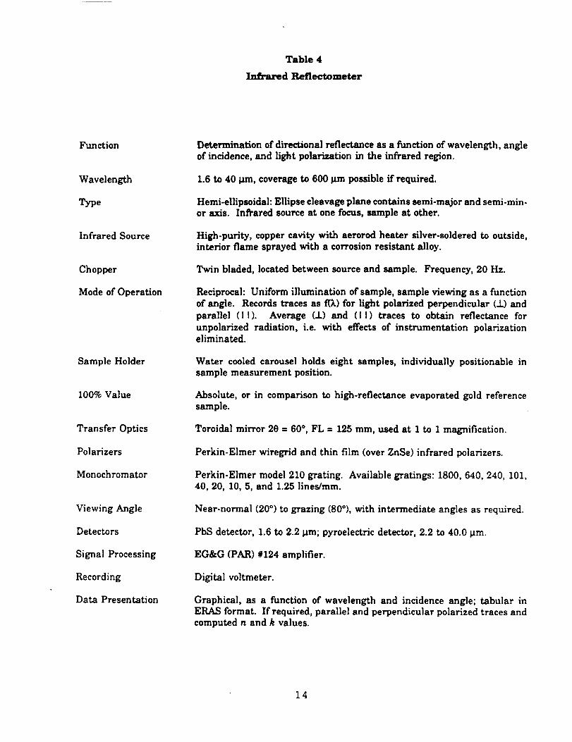
Table 4
Infrared Reflectometer
Function
Wavelength
Type
InfraredSource
Chopper
Mode ofOperation
Sample Holder
100% Value
Transfer Optics
Polarizers
Monochromator
Viewing Angle
Detectors
SignalProcessing
Recording
Data Presentation
Determination of directional reflectance as a function of wavelength, angleof incidence, and light polarization in the infrared region.
1.6 to 40 p,m, coverage to 600 ttrn possible if required.
Hemi-ellipsoidal: Ellipse cleavage plane contains semi-major and semi-min-or axis. Infrared source at one focus, sample at other.
High-purity, copper cavity with aerorod heater silver-seldered to outside,interior flame sprayed with a corrosion resistant alloy.
Twin bladed, located between source and sample. Frequency, 20 Hz.
Reciprocal: Uniform illumination of sample, sample viewing as a function
of angle. Records traces as f(_) for light polarized perpendicular (_t_)andparallel (I I). Average (.!.) and (I I) traces to obtain reflectance for
unpolarized radiation, i.e. with effects of instrumentation polarizationeliminated.
Water cooled carousel holds eight samples, individually positionable insample measurement position.
Absolute, or in comparison to high-reflectance evaporated gold referencesample.
Toroidal mirror 29 = 60 °, FL = 125 ram, used at 1 to 1 magnification.
Perkin-Elmer wiregrid and thin film (over ZnSe) infrared polarizers.
Perkin-Elmer model 210 grating. Available gratings: 1800, 640, 240, 101,40, 20, 10, 5, and 1.25 lines/ram.
Near-normal (20 °) to grazing (80°), with intermediate angles as required.
PbS detector, 1.6 to 2.2 Nm; pyroelectric detector, 2.2 to 40.0 _m.
EG&G (PAR) #124 amplifier.
Digitalvoltmeter.
Graphical,as a function of wavelength and incidenceangle;tabular inERAS format. Ifrequired,paralleland perpendicularpolarizedtracesand
computed n and k values.
14
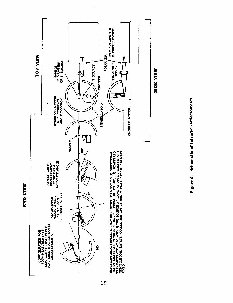
15
slitisimaged by the collectionopticson a 1"diameter sample disc.The specularlyand/or diffusely
reflectedslitimage isin turnimaged by thehemi-ellipsoidintothe IR sourceopening. The slitimage
on the sample (about 1/8"x 1/2")when reimaged by the ellipsoidon the source cavity,must fall
completelywithinthe confinesofthe IR cavityentrance. Given a uniform radiancefrom the cavity,
uniform illuminationof the slitimage on the sample over 2_ storadiansis provided? The large
diameter (12")and closelyspaced foci(2"separation)of the hemi-ellipsoidused make the geometric
deviationfrom ahemisphere minimal, but thisdeviationisallimportantinminimizing the sizeofthe
diffuselyreflectedslitimage at the cavityentrance,see reference2.
To allow performance of requiredfunctions,itis necessary to rotatethe overhead mirror,
togetherwith the collectionoptics,monochromator, and detector,in relationto the source,chopper,
and sample system. The rotationisperformed about an axisthrough the sample center,inthe plane
of the sample and parallelto the ellipsesemi-minor axis. This rotationis required (1)to allow
positioningthe mirror directlyabove the sample to measure the directionalreflectancewith the
specularcomponent eliminated,(2)toallowreflectancemeasurements as a functionofangle20 to80°,
and (3)to make a 100% measurement without use ofa referencestandard. The scatteringor zero
incidenceangle measurement (specularcomponent eliminated)isdiscussedbelow in Section5.1.4.
With thismechanism, angular measurements are routinelymade fornear-normal(20°),tograzingat
80°or greater.
Directionalreflectanceis,by definition,the ratioofthetotalreflectedradiationtothe radiation
incidentat a specifiedangle. Energy recorded when the sample isviewed by the overhead mirror
gives the reflecteddatum. The incidentdatum may be measured (1) directly(so-calledabsolute
method) or(2)derivedby a replacement ofthe sample with a standard ofknown reflectance,such as
evaporated goldon a smooth fused silicasubstrate.
The absolute100% measurement requiresremoving thesample from the measurement position
and rotatingthe overhead mirror to a locationbelow the plane of the ellipse,see Figure 6. In this
location,the overhead mirror receivesthe lightwhich fallson the sample position,thus allowing
measurement ofthe 100% datum.
The positioningof the overhead mirror in relationto the sample locationis an important
featureofthe reflectometer.Itcannot be accomplishedby simplyrotatingthe overhead mirroralone.
The entire optical train, overhead mirror, torroid, monochromator and detector must remain fixed in
relationship to each other; if the overhead mirror rotates, the entire train has to be rotated. This is
now actually feasible with design changes recently accomplished. But for solid (non-fluid samples),
the source-sample holder-chopper system is rotated, as shown in Figure 6.
Ibid.
16
5.1...__ Instrumentation Polarization
An unpolarizedbeam, aRer reflectionfrom a surface,may be polarizedto varying degrees,
depending on the angleofincidence,the compositionand roughness ofthe reflectingsurface,and the
wavelength oflight.For anglesofincidencenear-normal (el= 0 to about 20°)the reflectedbeam is
usually only nominally polarizedby reflection**,but at higher incidenceangles (40 to 90°),the
reflectedbeam from most samples shows pronounced polarization.
Gratingand prism monochromators, indispersingradiation,may introducepartialpolarization
to the beam. A lightbeam which ismade up of equal components of perpendicularand parallel
polarizedlight,upon passage through a monochromator, may emerge with unequally polarized
components. The degreeofpolarizationishighlywavelength dependent. For the instruments used,
the polarizationratio(parallel/perpendicular)rangesfrom 0.573,(Perkin-Elmer210) ismore than 4
(Cary 14).At high angles,errorsinreflectanceformaterialswhich on reflectiontend topolarizelight
can be very largeifeffectsofinstrumentationpolarizationare not eliminated.
I-npractice,the beam (orbeams in the dual beam Cary) ispolarizedparallelby a suitable
polarizerand thereflectanceoftheparallelpolarizedtraceisrecorded.The operationisrepeatedwith
the polarizerrotated90°. The traceforunpolarizedincidentradiationisderivedby averagingthe two
traces. This procedure istime consuming but providesthe correctresultsand provides additional
data,i.e.,at a given wavelength,the reflectanceforparalleland perpendicularpolarizedlight.From
these data,n and k valuesmay be calculated.
5.1.4 Normal (0 i = 0 °) and Grazing Incidence Measurements
The two reflectometersdescribedabove are based on similaroperating principles***and
thereforeshare certaincommon characteristics.Ifa measurement isattempted at normal incidence,
only the scatteredor "non-specular"reflectancewillbe recorded. For the Cary-sphere device,the
surfaceofthe sphere thatshouldprovidethe incidentradiationfora zeroincidenceangle isthe hole
through which the reflectedbeam leavesthe sphere. For the ellipsoidaldevice,the specularbeam is
similarlyeliminatedby the overhead mirror. There are instanceswhere itisdesiredtomeasure only
tl_ediffusereflectanceand use ismade ofthe zeroincidentangle.
** Multilayerstacksmay produce considerablepolarization,even at 20 degrees.
*** Sample subtends a dome ofuniform illumination,viewing from a narrow solidangle.
17
Measurementsat near-normal incidenceare limitedto angles no lessthan 20° from the
normal. This limitationisfixedby the sizeofthe opening in the CaD, sphere and the sample mirror
and geometry ofthe system in the ellipsoidaldevice..
A measurement angle at "grazing"incidenceon a 1" diameter sample is limitedin both
instruments. The grazing incidenceangle limitationisestablishedby the sizeof the sample and
geometricconsiderations.The image ofthe spectrometerentranceslitprojectedtothe sample surface
willultimatelyfalloffa finite-sizedsample as the angle ofincidenceapproaches 90°.
Angular measurements with the Cary-spheredevicemay be made to 80°using a 1"diameter
sample; with the ellipsoidaldevice,measurements are possibleat anglesgreaterthan 80°ifnarrow
monochromator slitsare used. The determiningfactorofthe slitwidth issignal-to-noisewhich isin
turn a functionofwavelength and the use ofpolarizers.Polarizersmust reduce signalstrength at
least50% and in practicereduce itas much as 80 to 90%. For reasons alreadymentioned, grazing
incidencemeasurements for polarizingsamples are usually of littlevalue without correctionfor
instrumentationpolarization.
5.1...._55 Performance Verification
The principalproblem in directionalreflectancemeasurements isthe availabilityof suitable
standards. Directionalreflectometersshould provide a correctreflectancevalue for a specularly
reflectingsample,a diffuselyreflecting(scattering)sample,ora sample which reflectspartofthelight
intoa specularlobeand scattersthe remainder. Calibrationstandardswhich may be correlatedwith
theoryare generallyspecularreflectors.The problem ofstandardshas been discussedin some detail
in a SAMSO reportby/LJ. Champetier and G.J.Friese.'The reportcompiles work done to resolve
discrepanciesindirectionalreflectance(ordirectionalemittance)obtainedon the same sample by three
differentlaboratories.The preferredstandardforthe IR regionispure,highlypolished(and therefore
specular)fused silica.A second choiceisevaporatedgold on a polishedglasssubstrate.
As alreadynoted,SOC uses two instrumentstocoverthe fullspectralregionfrom 0.3to 25.0
tlm. For both instruments,the errorisestimatedby comparison ofmeasured reflectancewith values
establishedby the National Bureau ofStandards (NBS) or with theoreticalvaluescalculatedfrom n
and k data in the literature.'
' Champetier, R.J.,and Friese,G.J.,"Use of PolishedFused Silicato Standardize DirectionalPolished Emittance and ReflectanceMeasurements in the Infrared",SAMSO Report TR-74-202,
SAMSO, Los Angeles Air Force Station,Los Angeles,CA 90054 (9August 1974).
18
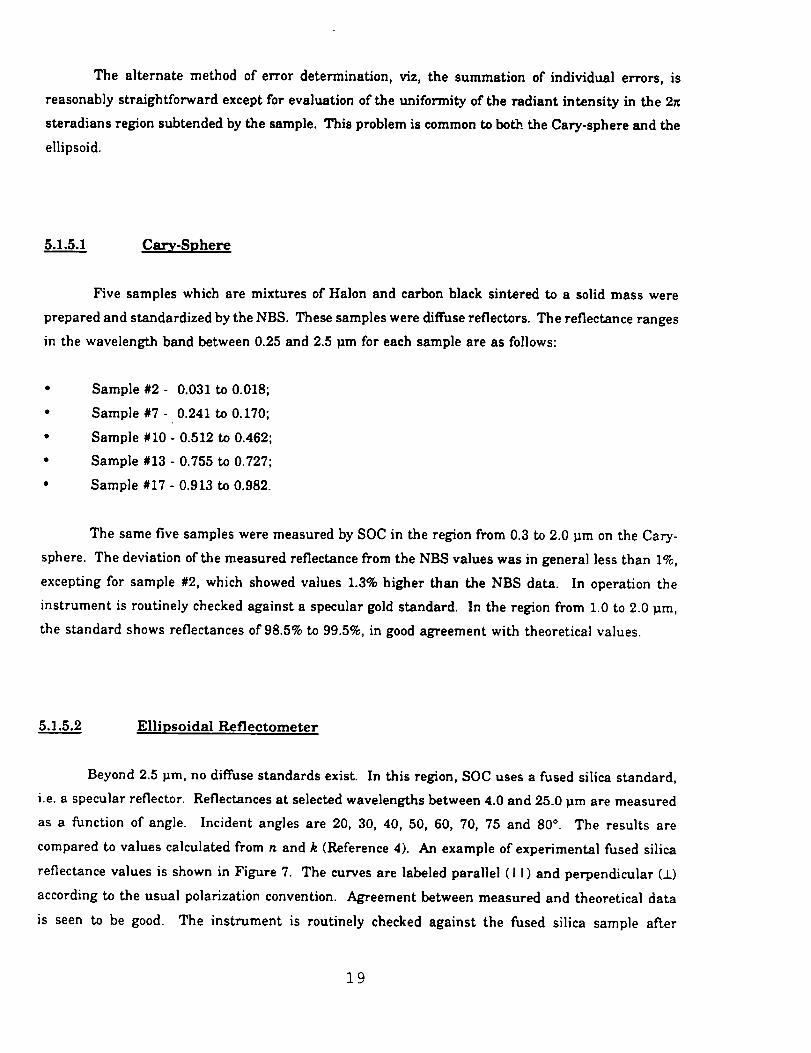
The alternatemethod of error determination,viz,the summation of individualerrors,is
reasonablystraightforwardexceptforevaluationofthe uniformityofthe radiantintensityin the 2_
steradiansregionsubtended by the sample. Thisproblem iscommon toboth the Cary-sphereand the
ellipsoid.
5.1.5.1 Cary-Sphere
Five samples which are mixtures ofHalon and carbon black sinteredto a solidmass were
prepared and standardizedby theNBS. These samples were diffusereflectors.The reflectanceranges
in the wavelength band between 0.25and 2.5_m foreach sample are as follows:
Sample #2 - 0.031 to 0.018;
Sample #7 - 0.241 to 0.170;
Sample #10 - 0.512 to 0.462;
Sample #13 - 0.755 to 0.727;
Sample #17 - 0.913 to 0.982.
The same five samples were measured by SOC in the region from 0.3 to 2.0 _m on the Cary-
sphere. The deviation of the measured reflectance from the NBS values was in general less than 1%,
excepting for sample #2, which showed values 1.3% higher than the NBS data. In operation the
instrument is routinely checked against a specular gold standard. In the region from 1.0 to 2.0 _m,
the standard shows reflectances of 98.5% to 99.5%, in good agreement with theoretical values.
5.1.5.2 Ellipsoidal Reflectometer
Beyond 2.5_m, no diffusestandardsexist.In thisregion,SOC uses a fused silicastandard,
i.e.a specularreflector.Reflectancesat selectedwavelengths between 4.0and 25.0 _m are measured
as a functionof angle. Incidentangles are 20, 30, 40, 50, 60, 70, 75 and 80°. The resultsare
compared tovalues calculatedfrom n and k (Reference4). An example ofexperimental fused silica
reflectancevalues isshown in Figure 7. The curvesare labeledparallel(II)and perpendicular(±)
accordingto the usual polarizationconvention.Agreement between measured and theoreticaldata
is seen to be good. The instrument is routinelychecked against the fused silicasample after
19
adjustments are made, aftera new source isinstalled,or ifno measurements have been made formore
than two weeks. At 16 _m, the standard ismeasured at eight angles and in both perpendicular and
parallel polarization modes and checked against theoreticalvalues in Reference 4. The agreement in
the average ± and It values isgenerally within 1% for angles from 20 to 70°; the 75 and 80° values
may be in error by as much as 3%.
1.0
0.9
16 Micrometers t
0.8 Z• Experimental
(I)o 0.7 --Calculated based on n and kc
u 0.6¢
n. 0.5 /co 0.4
- //00
c_ 0.3 I I
Average of Data (_, /
0.2 ' " /
0.1 /
0 10 20 30 40 50 60 70 80 900
Angles
Figure 7. Directional Reflectance of Fused Silica Standard at 16 _tm --
Perpendicular (_), Parallel ( I I ), and Average.
2O
6.__..0DATA REDUCTION AND PRESENTATION
Data reductionisby interactivemeans, usinga Sun 3/260computer with a CRT terminal(CIT-
101) and laserprinterwithin the SOC laboratoryfacility.Current working setsof data are stored
entirelywithinthe computer where they are immediately availabletothe terminaldisplay,eitheras
print-outinreport-readyformat or graphicalpresentation.This procedurehas eliminatedthe use of
keypunch formats.Another advantage isthe speed withwhich dataon new materialscan be acquired,
processedand transferred.Ifrequired,the system providescomputer-to-computertransferbetween
the SOC siteand a client'sfacilityvia telephonelines.
8..._I Codes for Data Reduction
Data obtained with all incoherent source instrumentation (Cary-Integrating Sphere, Infrared
Reflectometer) are processed by an interactive prompting system which eliminates the use of keypunch
formats. For the directional reflectance measurements, the programs automatically merge the data
collected by the Cary-Integrating Sphere and the Infrared Reflectometer.
6.1..._!1 Directional Reflectance Codes
Cary data (DR from 0.3 to 1.6 _m) are read from the instrument charts and entered into the
computer by means of a prompting system. Infrared data (DR from 1.2 to 40.0 _m) are read from
digital voltmeter printer tape and entered by prompting at each wavelength of interest. The raw data
are processed into reflectance data and formatted to the standard ERAS form? Two different classes
of data are recognized:
I. near-normal,unpolarizeddata (used largelyforthermal analysiscalculations);
. angular data collectedin both polarizations(used as a data base for signature
calculations).
5 Earing, D., "Support Information for Target System Measurements", Willow Run Laboratories,Institute of Science and Technology, The University of Michigan (December 1967).
21
The followingtypesofdata may be generated,depending on requirements:
I. Solar absorptanceas a functionofpolarincidenceangle;
. Integrated directionalemittance as a function of temperature and angle, and total
hemispherical emittance;
. Directionalreflectanceas a functionofwavelength and angle (includingperpendicularand
parallelpolarizationbranches and theiraverage);
.
_o
"Bestfit"values ofindex ofrefractionand extinctioncoefficient;
"Bestfit"Brewster angle.
Figures 8 and 9 show the data reductionprogram steps involved in the two classesof
reduction.
6._22 Data Presentation
Data ispresentedin both graphicaland tabularform. In both casesspecialsoftwareisused.
The tabulardata iscompiled in accordance with the ERAS format. In addition,allERAS formatted
data can be provided on tape.
22
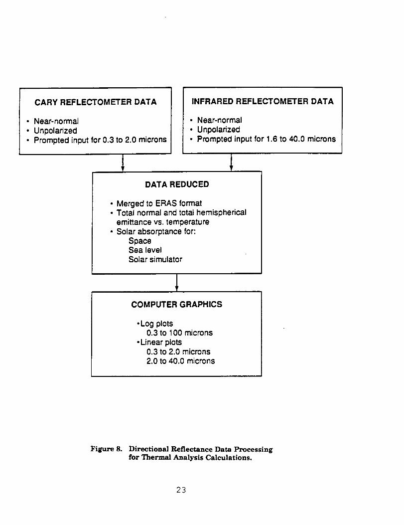
CARY REFLECTOMETER DATA
Near-normal
UnpolarizedPrompted input for 0.3 to 2.0 microns
INFRARED REFLECTOMETER DATA
• Near-normal
• Unpolarized• Prompted input for 1.6 to 40.0 microns
DATA REDUCED
• Merged to ERAS format• Total normal and total hemispherical
emittance vs. temperature
• Solar absorptance for:SpaceSea levelSolar simulator
COMPUTER GRAPHICS
• Log plots0.3 to 100 microns
• Linear plots0.3 to 2.0 microns2.0 to 40.0 microns
Figure 8. Directional Reflectance Data Processingfor Thermal Analysis Calculations.
23
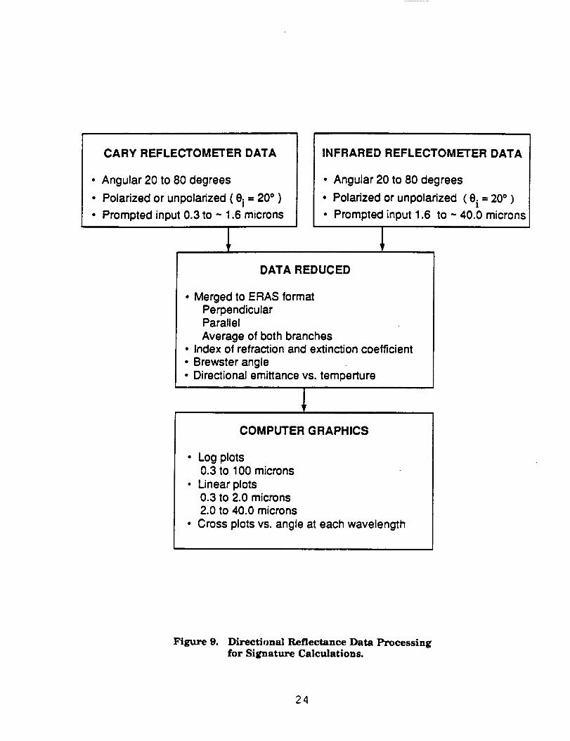
CARY REFLECTOMETER DATA
• Angular 20 to 80 degrees
• Polarized or unpolarized ( ei = 20 ° )
• Prompted input 0.3 to -- 1.6 microns
INFRARED REFLECTOMETER DATA
• Angular 20 to 80 degrees
• Polarized or unpolarized ( ei = 20° )
• Prompted input 1.6 to -- 40.0 microns
DATA REDUCED
• Merged to ERAS formatPerpendicularParallel
Average of both branches• Index of refraction and extinction coefficient
• Brewster angle
• Directional emittance vs. temperture
COMPUTER GRAPHICS
• Log plots0.3 to 100 microns
• Linear plots0.3 to 2.0 microns2.0 to 40.0 microns
• Cross plots vs. angle at each wavelength
Figure 9. Directional Reflectance Data Processingfor Signature Calculations.
24
APPENDIX A
SOUTHERN RESEARCH INSTITUTE
PW QUARTZFS5675:
INDEX TO APPENDIX A
FIGURE A-I.
FIGURE A-2.
FIGURE A-3.
TABLE A-1.
TABLE A-2.
FIGURE A-4.
FIGURE A-5.
FIGURE A-6.
PAGE NO.
DIRECTIONAL REFLECTANCE
Directional Reflectance vs. Wavelength, Bandwidth
1.6 to 26.0 micrometers, Data Corrected for Instrumentation
Polarization. Incident Azimuth Aligned with C ............................... A-3
Directional Reflectance vs. Wavelength, Bandwidth
1.6 to 2.0 micrometers, Data Corrected for Instrumentation
Polarization. Incident Azimuth Aligned with C ............................... A-4
Directional Reflectance vs. Wavelength, Bandwidth
2.2 to 26.0 micrometers, Data Corrected for Instrumentation
Polarization. Incident Azimuth Aligned with C ............................... A-5
Directional Reflectance vs. Wavelength - ERAS data,
Data Uncorrected for Instrumentation Polarization.
Incident Azimuth Aligned with C... .................................................. A-6
Directional Emittance as a Function of Incident Angle
and Temperature. Incident Azimuth Aligned with C ....................... A-7
Directional Reflectance vs. Wavelength, Bandwidth
1.6 to 26.0 micrometers, Data Corrected for Instrumentation
Polarization. Incident Azimuth Aligned with R ............................... A-8
Directional Reflectance vs. Wavelength, Bandwidth
1.6 to 2.0 micrometers, Data Corrected for Instrumentation
Polarization. Incident Azimuth Aligned with R ............................... A-9
Directional Reflectance vs. Wavelength, Bandwidth
2.2 to 26.0 micrometers, Data Corrected for Instrumentation
Polarization. Incident Azimuth Aligned with R ............................... A-10
A-1
APPENDIX A
TABLE A-3.
TABLE A-4.
INDEX TO APPENDIX A (continued)
PAGE NO.
DIREQTIONAL REFLECTANCE
Directional Reflectance vs. Wavelength - ERAS data,
Data Uncorrected for Instrumentation Polarization.
Incident Azimuth Aligned with R ..................................................... A-11
Directional Emittance as a Function of Incident Angle
and Temperature. Incident Azimuth Aligned with R ....................... A-12
A-2
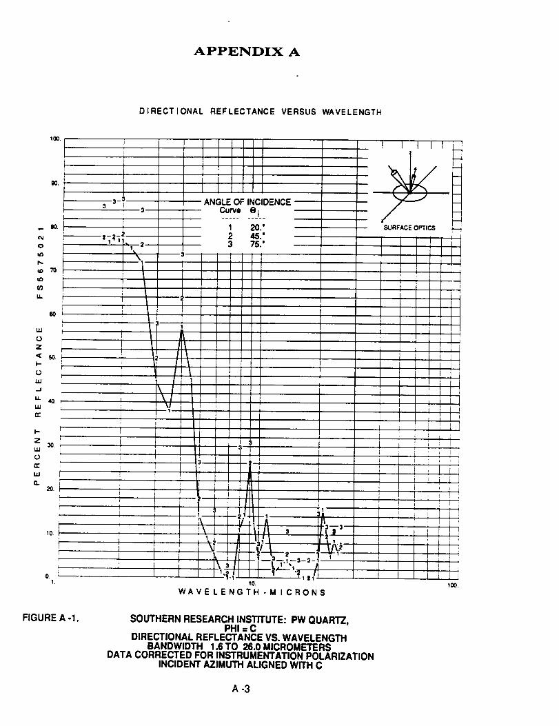
APPENDIX A
DIRECTIONAL REFLECTANCE VERSUS WAVELENGTH
100.
80,
o
t,ID
to
m
IJ,.
uJ
(D
Z
I--
(3
Lu.J
Lu
(Z
I-
Z
uJ
0
n-
LLI
O.
50,
40,
L
30_ r
i
E2o._
I
_o.
r
o_1.
ANGLE OF INCIDENCE
_.ej._1 20."
2 45."
3 75."
10.
WAVE LENGTH -M I CRONS100.
FIGURE A -1. SOUTHERN RESEARCH INSTITUTE: PW QUARTZ,PHI =C
DIRECTIONAL REFLECTANCE VS. WAVELENGTHBANDWIDTH 1.6 TO 26.0 MICROMETERS
DATA CORRECTED FOR INSTRUMENTATION POLARIZATIONINCIDENT AZIMUTH ALIGNED WiTH C
A-3
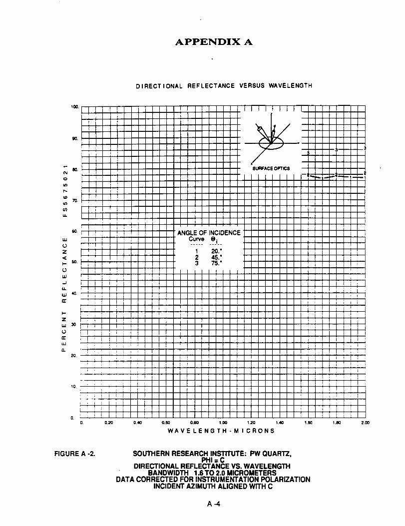
APPENDIX A
DIRECTIONAL REFLECTANCE VERSUS WAVELENGTH
tN
o
u3
to
03iJ,.
I.u
0
Z
<
0
w
I.L
I-
Z
l.u
0
rr
uJ
rl
30.
10.
O. 0.20 0.40 0.80 0.80 1.00 120 1.40 1.80
WAVE LENGTH - M I CRONS1.80 2.00
FIGURE A -2. SOUTHERN RESEARCH INSTITUTE: PW QUARTZ,PHI = C
DIRECTIONAL REFLECTANCE VS. WAVELENGTHBANDWIDTH 1.6 TO 2.0 MICROMETERS
DATA CORRECTED FOR INSTRUMENTATION POLARIZATIONINCIDENT AZIMUTH ALIGNED WITH C
A_
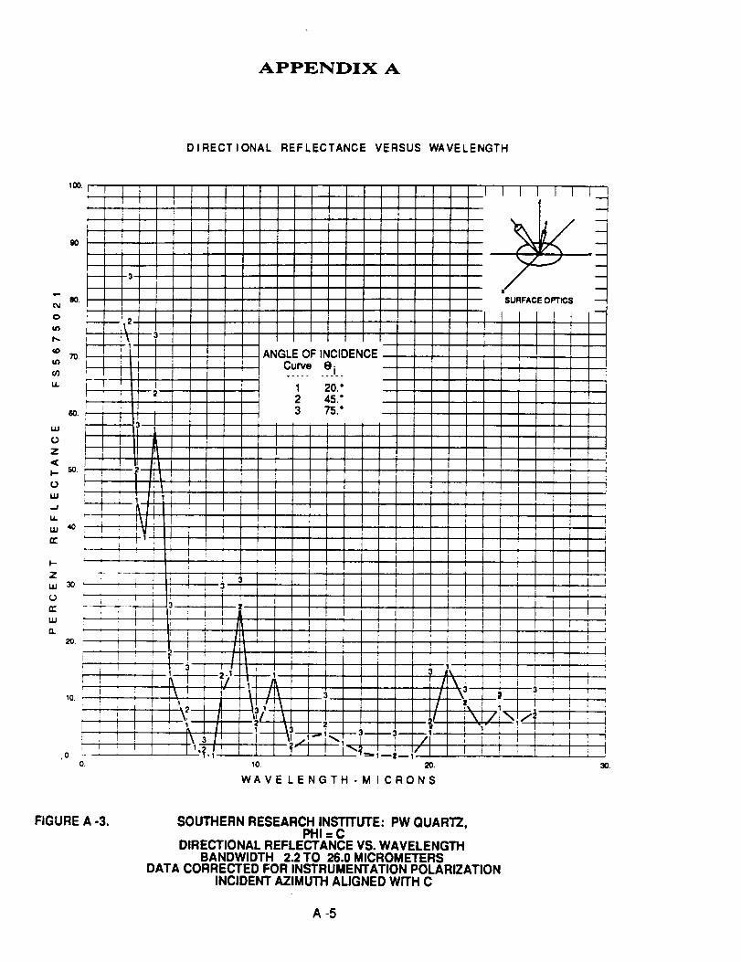
APPENDIX A
DIRECTIONAL REFLECTANCE VERSUS WAVELENGTH
o
Lt7
uJ
0
Z
I-
(3
LLI
.=f
t4.
14J
n"
l--
Z
LIJ
0
n"
UJ
a.
70
10
10 20.
WAVE LENGTH -M I CRONS
30.
FIGURE A -3. SOUTHERN RESEARCH INSTITUTE: PW QUARTZ,PHI = C
DIRECTIONAL REFLECTANCE VS. WAVELENGTHBANDWIDTH 2.2 TO 26.0 MICROMETERS
DATA CORRECTED FOR INSTRUMENTATION POLARIZATIONINCIDENT AZIMUTH ALIGNED WITH C
A-5
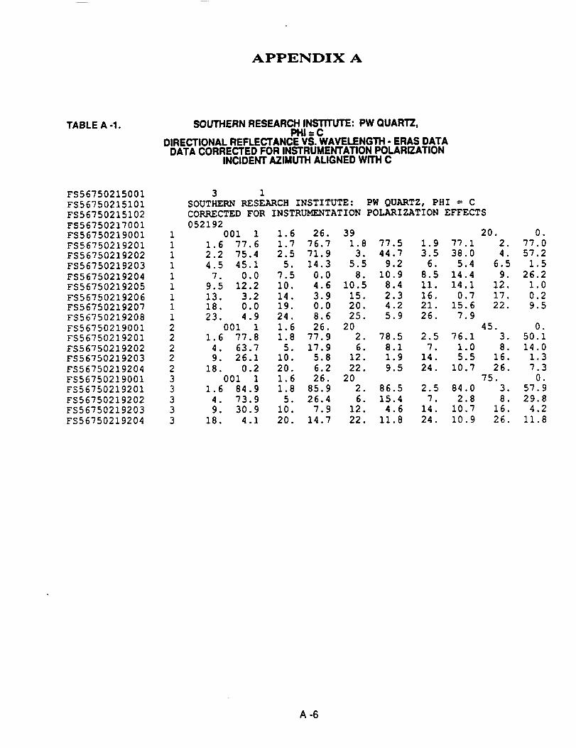
APPENDIX A
TABLE A -1. SOUTHERN RESEARCH INSTITUTE: PW QUAR'I-Z,PHI = C
DIRECTIONAL REFLECTANCE VS. WAVELENGTH- ERAS DATADATA CORRECTED FOR INSTRUMENTATIONPOLARIZATION
INCIDENT AZIMUTH ALIGNED WITH C
FS56750215001
FS56750215101
FS56750215102
FS56750217001
FS56750219001FS56750219201
FS56750219202
FS56750219203
FS56750219204
FS56750219205
FS56750219206
FS56750219207FS56750219208
FS56750219001FS56750219201
FS56750219202FS56750219203
FS56750219204
FS56750219001
FS56750219201
FS56750219202
FS56750219203
FS56750219204
3 1
SOUTHERN RESEARCH INSTITUTE: PW QUARTZ, PHI = C
CORRECTED FOR INSTRUMENTATION POLARIZATION EFFECTS
0521921 001 1 1.6 26. 39 20. 0.
1 1.6 77.6 1.7 76.7 1.8 77.5 1.9 77.1 2. 77.0
1 2.2 75.4 2.5 71.9 3. 44.7 3.5 38.0 4. 57.2
1 4.5 45.1 5. 14.3 5.5 9.2 6. 5.4 6.5 1.5
1 7. 0.0 7.5 0.0 8. 10.9 8.5 14.4 9. 26.2
1 9.5 12.2 10. 4.6 10.5 8.4 Ii. 14.1 12. 1.0
1 13. 3.2 14. 3.9 15. 2.3 16. 0.7 17. 0.21 18. 0.0 19. 0.0 20. 4.2 21. 15.6 22. 9.5
1 23. 4.9 24. 8.6 25. 5.9 26. 7.9
2 001 1 1.6 26. 20 45. 0.2 1.6 77.8 1.8 77.9 2. 78.5 2.5 76.1 3. 50.1
2 4. 63.7 5. 17.9 6. 8.1 7. 1.0 8. 14.02 9. 26.1 10. 5.8 12. 1.9 14. 5.5 16. 1.3
2 18. 0.2 20. 6.2 22. 9.5 24. 10.7 26. 7.3
3 001 1 1.6 26. 20 75. 0.
3 1.6 84.9 1.8 85.9 2. 86.5 2.5 84.0 3. 57.9
3 4. 73.9 5. 26.4 6. 15.4 7. 2.8 8. 29.8
3 9. 30.9 10. 7.9 12. 4.6 14. 10.7 16. 4.2
3 18. 4.1 20. 14.7 22. 11.8 24. 10.9 26. 11.8
A-6
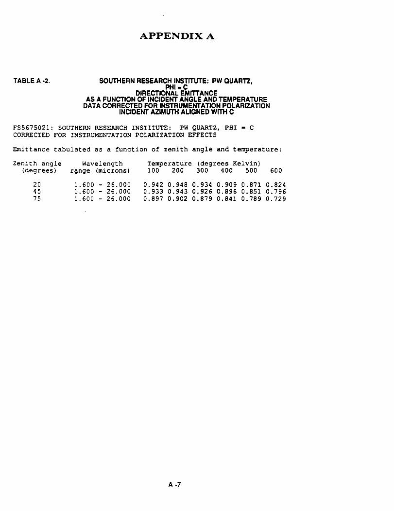
APPENDIX A
TABLE A -2. SOUTHERN RESEARCH INSTITUTE: PW QUARTZ,PHi = C
DIRECTIONAL EMITTANCEAS A FUNCTION OF INCIDENT ANGLE AND TEMPERATURE
DATA CORRECTED FOR INSTRUMENTATION POLARIZATIONINCIDENT AZIMUTH ALIGNED WITH C
FS5675021: SOUTHERN RESEARCH INSTITUTE: PW QUARTZ, PHI = C
CORRECTED FOR INSTRUMENTATION POLARIZATION EFFECTS
Emittance tabulated as a function of zenith angle and temperature:
Zenith angle Wavelength
(degrees) r@nge (microns)
Temperature (degrees Kelvin)100 200 300 400 500 600
20
45
75
1.600 - 26.0001.600 - 26.000
1.600 - 26.000
0.942 0.948 0.934 0.909 0. 871 0.8240.933 0.943 0.926 0.896 0.851 0.796
0.897 0.902 0.879 0.841 0.789 0.729
A-7
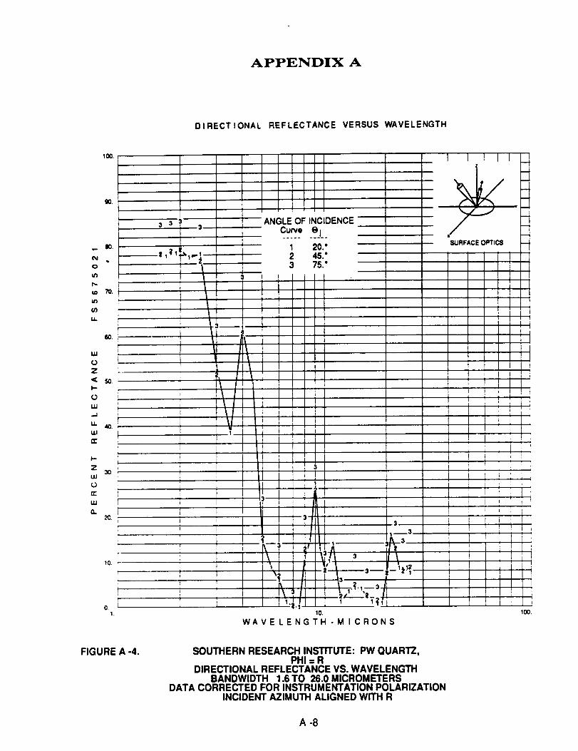
APPENDIX A
DIRECTIONAL REFLECTANCE VERSUS WAVELENGTH
0
_D
_J3
L_
W
0
Z
ot_
.J
It.
UJ
n"
i--
Z
UJ
0
n-
UJ
Q.
100.
90.
3 33
80
II
i
, ir
\i i i 3
10.
WAVE LENGTH - M I CRONS
1 l I I I _
SURFACE OPTIC8
t
tII
|
FIGURE A -4. SOUTHERN RESEARCH INSTITUTE: PW QUARTZ,PHI = R
DIRECTIONAL REFLECTANCE VS. WAVELENGTHBANDWIDTH 1.6 TO 26.0 MICROMETERS
DATA CORRECTED FOR INSTRUMENTATION POLARIZATIONINCIDENT AZIMUTH ALIGNED WITH R
A-8
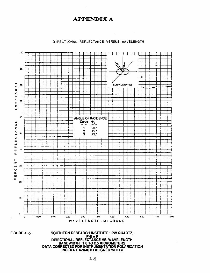
APPENDIX A
DIRECTIONAL REFLECTANCE VERSUS WAVELENGTH
1.80 2,00
FIGURE A -5. SOUTHERN RESEARCH INSTITUTE: PW QUARTZ,PHI = R
DIRECTIONAL REFLECTANCE VS. WAVELENGTHBANDWIDTH 1.6 TO 2.0 MICROMETERS
DATA CORRECTED FOR INSTRUMENTATION POLARIZATIONINCIDENT AZIMUTH ALIGNED WITH R
A-9
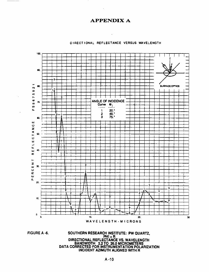
APPENDIX A
DIRECTIONAL REFLECTANCE VERSUS WAVELENGTH
1 II ;
! i ,
ii i
I : Ii i I Ji i : :
i Ii
' I
!i ]
: I !Ii
III
IiI
I ' : I
uJ
o..
o. lo.
I
i
i
;i
i I
If
WAVE LENGTH - M I CRONS
FIGURE A -6. SOUTHERN RESEARCH INSTITUTE: PW QUARTZ,PHI = R
DIRECTIONAL REFLECTANCE VS. WAVELENGTHBANDWIDTH 2.2 TO 26.0 MICROMETERS
DATA CORRECTED FOR INSTRUMENTATION POLARIZATIONINCIDENT AZIMUTH ALIGNED WITH R
A -I0
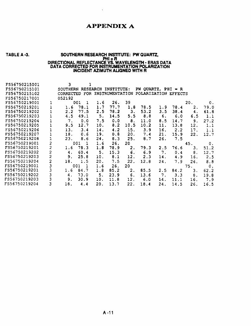
APPENDIX A
TABLE A -3. SOUTHERN RESEARCH INSTITUTE: PW GUAITI-Z,PHI:R
DIRECTIONAL REFLECTANCE VS. WAVELENGTH - ERAS DATADATA CORRECTED FOR INSTRUMENTATION POLARIZATION
INCIDENT AZIMUTH ALIGNED WITH R
FS56750215001 3 1
FS56750215101 SOUTHERN RESEARCH INSTITUTE: PW QUARTZ, PHI = RFS56750215102 CORRECTED FOR INSTRUMENTATION POLARIZATION EFFECTS
FS56750217001 052192
FS56750219001 1 001 1 1.6 26. 39
FS56750219201 1 1.6 78.1 1.7 77.7 1.8 78.5 1.9FS56750219202 1 2.2 77.5 2.5 78.2 3. 53.2 3.5
FS56750219203 1 4.5 49.1 5. 14.5 5.5 8.8 6.
FS56750219204 1 7. 0.0 7.5 0.0 8. Ii.0 8.5
FS56750219205 1 9.5 12.7 i0. 8.2 10.5 10.2 II.
FS56750219206 1 13. 3.4 14. 4.2 15. 3.9 16.FS56750219207 1 18. 0.6 19. 0.8 20. 7.4 21.
FS56750219208 1 23. 8.6 24. 8.3 25. 8.7 26.
FS56750219001 2 001 1 1.6 26. 20FS56750219201 2 1.6 78.3 1.8 78.9 2. 79.3 2.5
FS56750219202 2 4. 60.4 5. 15.3 6. 6.9 7.
FS56750219203 2 9. 25.8 I0. 8.1 12. 2.3 14.
FS56750219204 2 18. 1.5 20. 7.5 22. 12.8 24.
FS56750219001 3 001 1 1.6 26. 20FS56750219201 3 1.6 84.7 1.8 85.2 2. 85.5 2.5
FS56750219202 3 4. 73.0 5. 23.9 6. 13.6 7.FS56750219203 3 9. 30.9 I0. 11.8 12. 6.0 14.
FS56750219204 3 18. 4.4 20. 13.7 22. 18.4 24.
78.4
38.46.0
14.7
13.8
2.2
15.9
7.5
76.6
0.4
4.9
7.9
84.2
3.3ii.I
14.5
20.
,
4.
6.5
9.
12.
17.
22.
45.
3.
8.
16.
26.
75.
3.
8.
16.
26.
o
79.0
61 8
1 1
27 2
1 1
1 1
12 7
,
51.2
12.7
2.5
8.8
0.
62.2
19.8
7.9
16.5
A -11
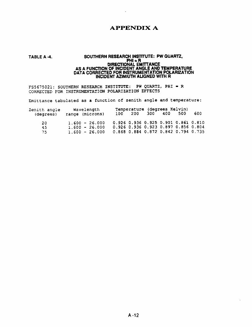
APPENDIX A
TABLE A -4. SOUTHERN RESEARCH INSTITUTE: PW QUARTZ,PHI:R
DIRECTIONAL EMITTANCEAS A FUNCTION OF INCIDENT ANGLE AND TEMPERATURE
DATA CORRECTED FOR INSTRUMENTATION POLARIZATIONINCIDENT AZIMIUTH ALIGNED WiTH R
FS5675021: SOUTHERN RESEARCH INSTITUTE: PW QUARTZ, PHI ffi R
CORRECTED FOR INSTRUMENTATION POLARIZATION EFFECTS
Emittance tabulated as a function of zenith angle and temperature:
Zenith angle Wavelength(degrees) range (microns)
Temperature (degrees Kelvin)i00 200 300 400 500 600
20
45
75
1.600 - 26.000
1.600 - 26.000
1.600 - 26.000
0.926 0.936 0.925 0.901 0.861 0.8100.926 0.936 0.923 0.897 0.856 0.804
0.868 0.884 0.872 0.842 0.794 0.735
A -12

APPENDIX D
THERMAL ANALYSIS COMPUTER PROGRAM SOURCE CODE

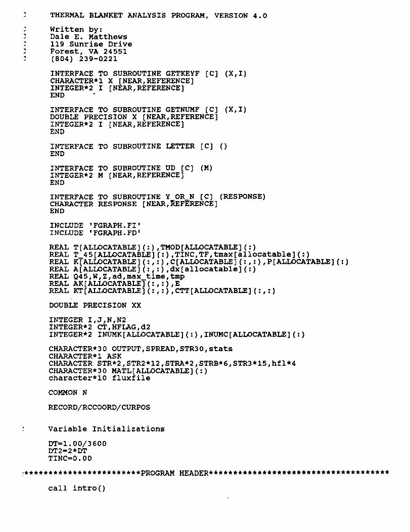
THERMAL BLANKET ANALYSIS
Written by:Dale E. Matthews
119 Sunrise Drive
Forest, VA 24551
(804) 239-0221
PROGRAM, VERSION 4.0
INTERFACE TO SUBROUTINE GETKEYF
CHARACTER*I X [NEAR,REFERENCE]
INTEGER*2 I [NEAR,REFERENCE]END
[c] (X,I)
INTERFACE TO SUBROUTINE GETNUMF [C]
DOUBLE PRECISION X [NEAR,REFERENCE]
INTEGER*2 I [NEAR,REFERENCE]END
(X,I)
INTERFACE TO SUBROUTINE LETTER [C] ()END
INTERFACE TO SUBROUTINE UD [C]
INTEGER*2 M [NEAR,REFERENCE]END
(M)
INTERFACE TO SUBROUTINE Y_OR N [C] (RESPONSE)CHARACTER RESPONSE [NEAR,REFERENCE]END
INCLUDE 'FGRAPH.FI'
INCLUDE 'FGRAPH.FD'
REAL T[ALLOCATABLE] (:),TMOD[ALLOCATABLE] (:)
REAL T 45 [ALLOCATABLE] ( :) ,TINC,TF,tmax[allocatable] ( :)REAL KTALLOCATABLE ] (:, :), C [ALLOCATABLE ] ( :, :), P [ALLOCATABLE ] ( : )
REAL A[ALLOCATABLE] (:, :) ,dx[allocatable] ( : )REAL Q45,W,Z,ad,max time,tmp
REAL AK [ALLOCATABLE ] (:, :), E
REAL KT [ALLOCATABLE ] (:, :), CTT [ALLOCATABLE ] (:, : )
DOUBLE PRECISION XX
INTEGER I,J,N,N2
INTEGER*2 CT,HFLAG,d2
INTEGER*2 INUMK[ALLOCATABLE](:),INUMC[ALLOCATABLE](:)
CHARACTER*30 OUTPUT,SPREAD,STR30,statsCHARACTER*I ASK
CHARACTER STR*2,STR2*I2,STRA*2,STRB*6,STR3*I5,hfI*4
CHARACTER*30 MATL[ALLOCATABLE](:)character*10 fluxfile
COMMON N
RECORD/RCCOORD/CURPOS
call intro()

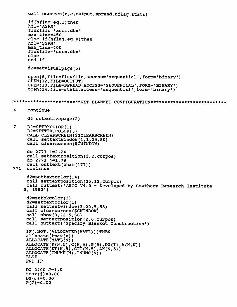
call oscreen(n,e,output,spread,hflag,stats)
if(hflag.eq.l)thenhfI='ASRM'fluxfile='asrm.dbx'
max time=450
else if(hflag.eq.0)thenhfI='SSRM'
max time=400fluxfile='ssrm.dbx'
else
end if
d2=setvisualpage(5)
open(6,file=fluxfile,access='sequential',form='binary')OPEN(12,FILE=OUTPUT)
OPEN(13,FILE=SPREAD,ACCESS='SEQUENTIAL',FORM='BINARY')
open(14,file=stats,access='sequential',form='binary')
4 continue
771
d2=setactivepage(2)
D2=SETBKCOLOR(1)
D2=SETTEXTCOLOR(3)
CALL CLEARSCREEN($GCLEARSCREEN)
call settextwindow(l,l,25,80)call clearscreen($GWINDOW)
do 2771 i=2,24
call settextposition(i,2,curpos)do 2771 j=i,78
call outtext(char(177))continue
d2=settextcolor(14)
call settextposition(25,12,curpos)
call outtext('ASTC V4.0 - Developed$, 1992')
by Southern Research Institute
d2=setbkcolor(3)
d2=settextcolor(1)
call settextwindow(3,22,5,58)
call clearscreen($GWINDOW)call sbox(3,22,5,58)
call settextposition(2,6,curpos)
call outtext('Specify Blanket Construction')
IF (. NOT. (ALLOCATED (MATL)) )THENallocate (tmax (n))
ALLOCATE (MATL (N))
ALLOCATE (K(N, 5),C(N, 5), P(5), DX(I),A(N,N) )
ALLOCATE (KT (N, 5), CTT (N, 5), AK (N, 5) )ALLOCATE (INUMK (N), INUMC (N))ELSE
END IF
DO 2400 J=I,Ntmax(j)=0.00
DX(J)=0.00
P(J)=0.00

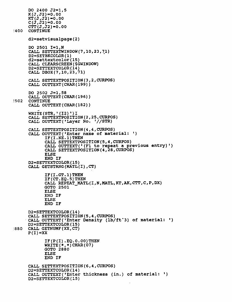
',400
DO 2400 J2=I,5
K(J,J2) =0.00KT (J,J2) =0.00
C(J,J2) =0.00
CTT(J,J2) =0.00CONTINUE
d2=setvisualpage(2)
DO 2501 I=I,N
CALL SETTEXTWINDOW(7,10,23,71)D2=SETBKCOLOR(1)
d2=settextcolor(15)
CALL CLEARSCREEN($GWINDOW)D2=SETTEXTCOLOR(14)
CALL DBOX(7,10,23,71)
CALL SETTEXTPOSITION(3,2,CURPOS)
CALL OUTTEXT(CHAR(199))
_502
DO 2502 J=1,58
CALL OUTTEXT(CHAR(196))CONTINUE
CALL OUTTEXT(CHAR(182))
WRITE (STR, ' (12 ) ')I
CALL SETTEXTPOSITION(2,25,CURPOS)
CALL OUTTEXT('Layer No. '//STR)
CALL
CALL
SETTEXTPOS ITION (4 ,4 ,CURPOS)
OUTTEXT( 'Enter name of material: ')
IF(I.NE. I) THEN
CALL SETTEXTPOSITION (5,4, CURPOS)CALL OUTTEXT('(FI to repeat a previous
CALL SETTEXTPOSITION (4,28, CURPOS)ELSE
END IF
D2=SETTEXTCOLOR(15)CALL GETSTRNG(MATL(I),CT)
entry) ')
IF (I. GT. I) THEN
IF (CT. EQ. 5) THEN
CALL REPEAT_MATL (I, N, MATL, KT, AK, CTT, C, P, DX)GOTO 2501
ELSE
END IF
ELSE
END IF
:880
D2=SETTEXTCOLOR(14)CALL SETTEXTPOSITION(5,4,CURPOS)
CALL OUTTEXT('Enter Density (lb/ftA3)
D2=SETTEXTCOLOR(15)
CALL GETNUMF(XX,CT)
P (I )=XX
of material: ')
IF (P(I) .EQ. 0.00) THEN
WRITE (*, *) CHAR (07)GOTO 2880
ELSE
END IF
CALL SETTEXTPOSITION(6,4,CURPOS)
D2=SETTEXTCOLOR(14)
CALL OUTTEXT('Enter thickness (in.)
D2=SETTEXTCOLOR(15)
of material: ')

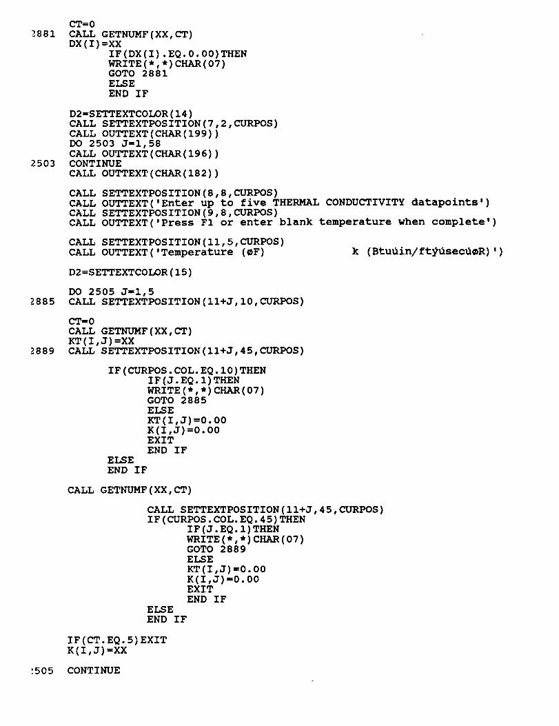
_-881CT=0CALL GETNUMF (XX, CT)
DX (I )--XX
IF(DX (I) .EQ. 0.00) THENWRITE (*, *) CHAR (07)GOTO 2881
ELSE
END IF
2503
D2=SETTEXTCOLOR(14)CALL SETTEXTPOSITION(7,2,CURPOS)
CALL OUTTEXT(CHAR(199))DO 2503 J=i,58
CALL OUTTEXT(CHAR(196))CONTINUE
CALL OUTTEXT(CHAR(182))
CALL SETTEXTPOSITION(8,8,CURPOS)
CALL OUTTEXT('Enter up to five THERMAL CONDUCTIVITY datapoints')
CALL SETTEXTPOSITION(9,8,CURPOS)CALL OUTTEXT('Press F1 or enter blank temperature when complete')
CALL SETTEXTPOSITION(ll,5,CURPOS)
CALL OUTTEXT('Temperature (_F) k (Btu_in/ftg_sec_R)')
D2=SETTEXTCOLOR(15)
2885DO 2505 J=l,5
CALL SETTEXTPOSITION(II+J,10,CURPOS)
2889
CT=0
CALL GETNUMF(XX,CT)
KT(I,J)=XXCALL SETTEXTPOSITION(II+J,45,CURPOS)
IF (CURPOS. COL. EQ. i0) THEN
IF (J. EQ. i) THEN
WRITE (*, *) CHAR (07)GOTO 2885
ELSE
KT(I,J) =0.00
K(I,J)=0.00EXITEND IF
ELSE
END IF
CALL GETNUMF(XX,CT)
CALL S ETTEXTPOS ITION (1 l+J, 45, CURPOS )IF (CURPOS. COL. EQ. 45) THEN
IF (J. EQ. i) THEN
WRITE(*, *) CHAR (07)GOTO 2889
ELSE
KT(I,J) =0.00
K(I,J)--0.00EXIT
END IF
ELSE
END IF
IF(CT.EQ.5)EXIT
K(I,J)=XX
_505 CONTINUE

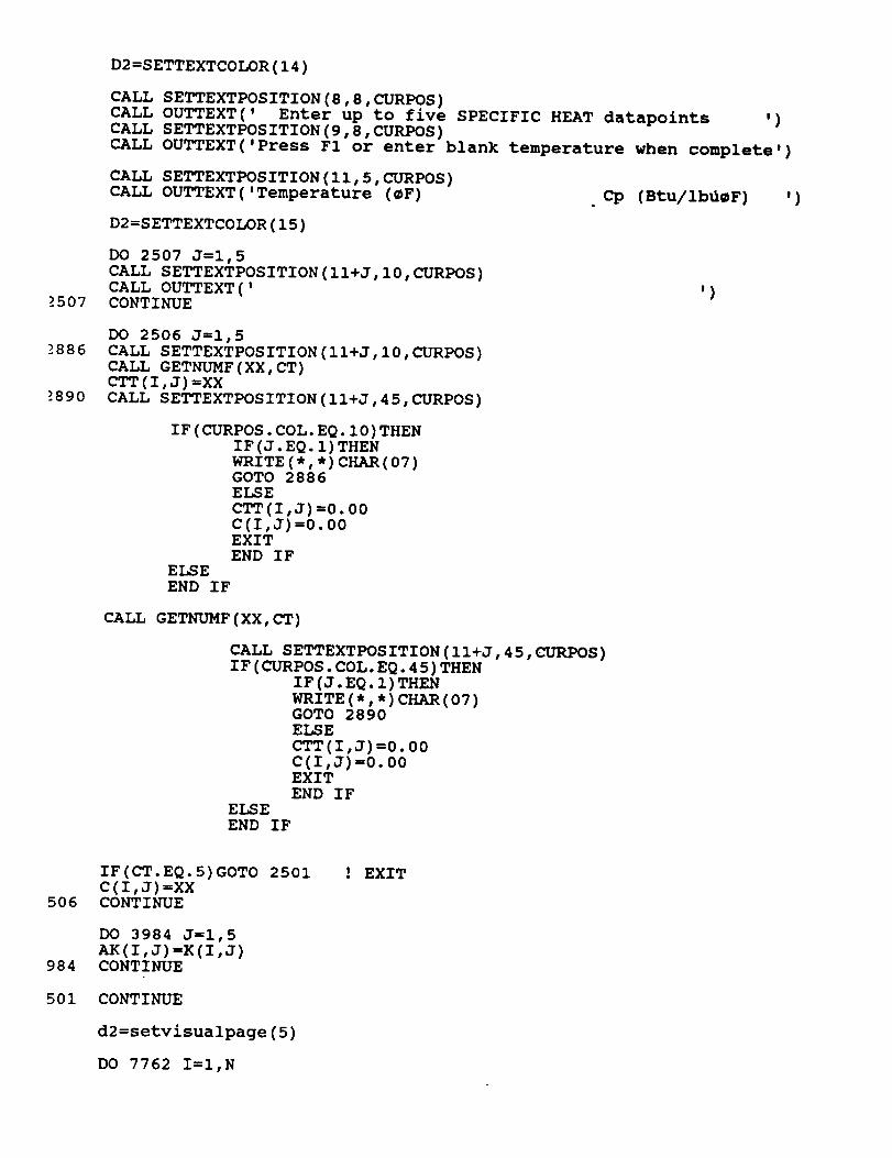
2507
-)886
-)890
D2 =SETTEXTCOLOR (14 )
CALL SETTEXTPOSITION(8,8,CURPOS)
CALL OUTTEXT(' Enter up to five SPECIFIC HEAT datapoints ,)CALL SETTEXTPOSITION(9,8,CURPOS)
CALL OUTTEXT('Press F1 or enter blank temperature when complete')
CALL SETTEXTPOSITION(I1,5,CURPOS)CALL OUTTEXT('Temperature (_F)
D2 =S ETTEXTCOLOR (15 )
DO 2507 J=l,5
CALL SETTEXTPOSITION(II+J,10,CURPOS)CALL OUTTEXT('CONTINUE
Cp (Btu/ib_F) ,)
,)
DO 2506 J=l,5
CALL SETTEXTPOSITION(II+J,10,CURPOS)CALL GETNUMF(XX,CT)CTT(I,J)=XX
CALL SETTEXTPOSITION(I1+J,45,CURPOS)
IF (CURPOS. COL. EQ. I0) THENIF (J. EQ. i) THEN
WRITE (*, *) CHAR (07)GOTO 2886ELSE
CTT(I,J) =0.00C(I,J)=0.00EXIT
END IFELSE
END IF
CALL GETNUMF (XX, CT)
CALL SETTEXTPOSITION(II+J,45,CURPOS)IF(CURPOS.COL.EQ.45)THEN
I F (J. EQ. 1 )THEN
WRITE (*, *) CHAR (07)GOTO 2890
ELSE
CTT(I,J)=0.00
C(I,J)=0.00EXIT
END IF
ELSE
END IF
506
984
501
IF(CT.EQ.5)GOTO 2501
C(I,J)=XXCONTINUE
DO 3984 J=l,5
AK(I,J) =K(I,J)CONTINUE
CONTINUE
d2=setvisualpage(5)
DO 7762 I=I,N
! EXIT

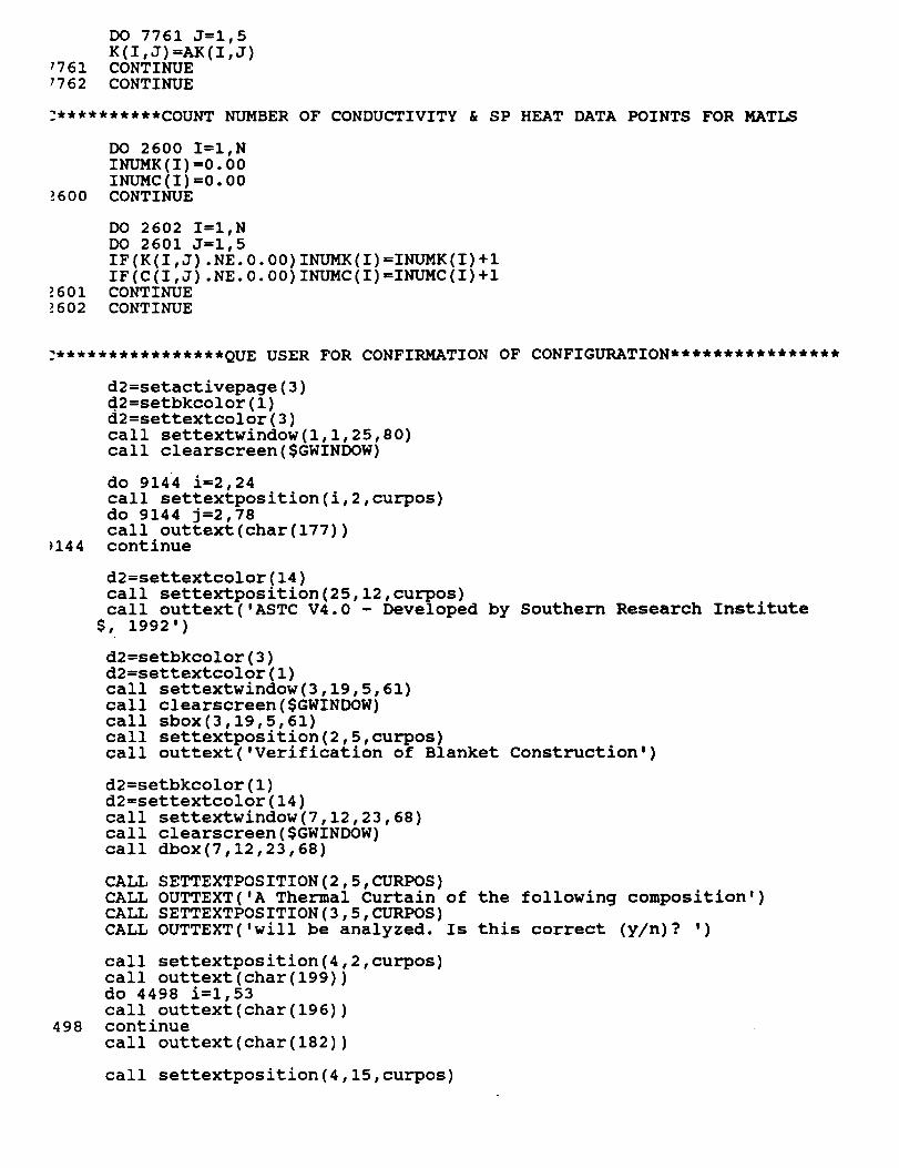
DO 7761 J=l,5
K(I,J)=AK(I,J)7761 CONTINUE
7762 CONTINUE
2**********COUNT NUMBER OF CONDUCTIVITY & SP HEAT DATA POINTS FOR MATLS
_600
DO 2600 I=I,N
INUMK (I) =0.00INUMC (I) =0.00CONTINUE
_601_602
DO 2602 I=I,N
DO 2601 J=l,5
IF(K(I,J) .NE. 0.00) INUMK(I) =INUMK(I) +I
IF (C (I,J) .NE. 0.00) INUMC (I)=INUMC (I) +iCONTINUECONTINUE
:****************QUE USER FOR CONFIRMATION OF CONFIGURATION****************
)144
d2=setactivepage(3)
d2=setbkcolor(1)
d2=settextcolor(3)
call settextwindow(1,1,25,80)call clearscreen($GWINDOW)
do 9144 i=2,24
call settextposition(i,2,curpos)
do 9144 j=2,78call outtext(char(177))continue
d2=settextcolor(14)
call settextposition(25,12,curpos)call outtext('ASTC V4.0 - Developed by Southern Research Institute
$, 1992')
d2=setbkcolor(3)d2=settextcolor(1)
call settextwindow(3,19,5,61)
call clearscreen($GWINDOW)
call sbox(3,19,5,61)
call settextposition(2,5,curpos)call outtext('Verification of Blanket Construction')
d2=setbkcolor(1)
d2=settextcolor(14)
call settextwindow(7,12,23,68)
call clearscreen($GWINDOW)
call dbox(7,12,23,68)
498
CALL SETTEXTPOSITION(2,5,CURPOS)
CALL OUTTEXT('A Thermal Curtain of the following composition')
CALL SETTEXTPOSITION(3,5,CURPOS)
CALL OUTTEXT('will be analyzed. Is this correct (y/n)? ')
call settextposition(4,2,curpos)
call outtext(char(199))do 4498 i=i,53
call outtext(char(196))continue
call outtext(char(182))
call settextposition(4,15,curpos)

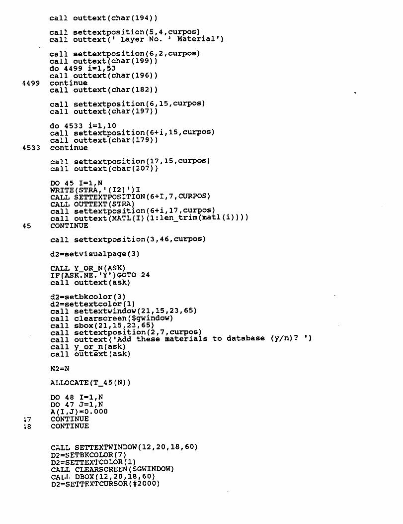
4499
4533
45
_7_8
call outtext(char(194))
call settextposition(5,4,curpos)call outtext(' Layer No. ' Material')
call settextposition(6,2,curpos)
call outtext(char(199))
do 4499 i=I,53
call outtext(char(196))continue
call outtext(char(182))
call settextposition(6,15,curpos)
call outtext(char(197))
do 4533 i=l,10
call settextposition(6+i,15,curpos)
call outtext(char(179))continue
call settextposition(17,15,curpos)call outtext(char(207))
DO 45 I=I,N
WRITE (STRA, '(I2)')ICALL SETTEXTPOSITION(6+I,7,CURPOS)
CALL OUTTEXT(STRA)
call settextposition(6+i,17,curpos)call outtext(MATL(I)(l:len_trim(matl(i))))CONTINUE
call settextposition(3,46,curpos)
d2=setvisualpage(3)
CALL Y OR_N (ASK)
IF(ASK?NE.'Y')GOTO 24
call outtext(ask)
d2=setbkcolor(3)
d2=settextcolor(1)call
call
callcall
call
call
call
settextwindow(21,15,23,65)
clearscreen($gwindow)
sbox(21,15,23,65)settextposition(2,7,curpos)outtext('Add these materials to
y_or_n(ask)
outtext(ask)
database
N2=N
ALLOCATE (T_45 (N))
DO 48 I=I,N
DO 47 J=I,N
A(I,J)=0.000CONTINUE
CONTINUE
(y/n) ? ,)
CALL SETTEXTWINDOW(12,20,18,60)
D2=SETBKCOLOR(7)
D2=SETTEXTCOLOR(1)
CALL CLEARSCREEN($GWINDOW)
CALL DBOX(12,20,18,60)D2=SETTEXTCURSOR(#2000)

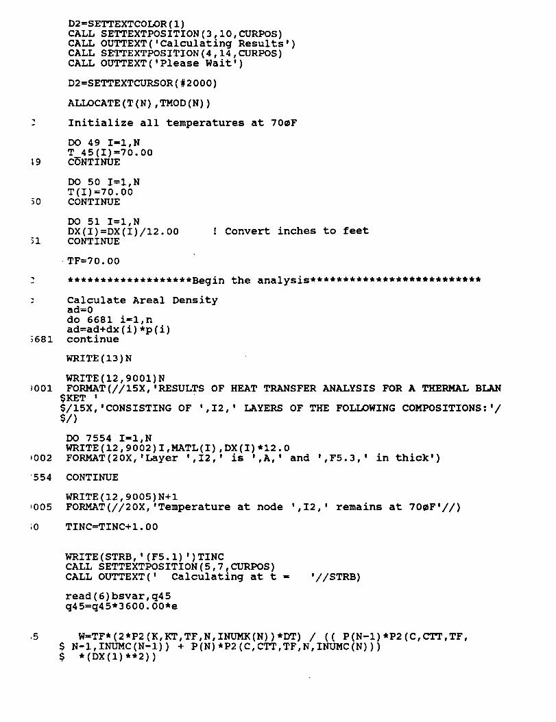
_9
30
_681
_001
_002
'554
,005
_0
D2=SETTEXTCOLOR(1)
CALL SETTEXTPOSITION(3,10,CURPOS)
CALL OUTTEXT('Calculatin, Results')CALL SETTEXTPOSITION(4,14,CURPOS)
CALL OUTTEXT('Please Wait')
D2=SETTEXTCURSOR(#2000)
ALLOCATE (T (N), TMOD (N))
Initialize all temperatures at 70_F
DO 49 I=I,N
T 45(I)=70.00CONTINUE
DO 50 I=I,NT(I)=70.00CONTINUE
DO 51 I=I,N
DX (I) =DX (I)/12.00CONTINUE
! Convert inches to feet
TF=70.00
Calculate Areal Densityad=0
do 6681 i=l,n
ad=ad+dx(i)*p(i)continue
WRITE (13 ) N
WRITE(12,9001)N
FORMAT(//15X,'RESULTS OF HEAT TRANSFER ANALYSIS FOR A THERMAL BLAN$KET '
$/15X,'CONSISTING OF ',I2,' LAYERS OF THE FOLLOWING COMPOSITIONS:'/
$/)
DO 7554 I=I,NWRITE (12,9002) I,MATL(I), DX(I)*12.0
FORMAT(20X,'Layer ',I2, ' is ',A,' and ',F5.3,' in thick')
CONTINUE
WRITE(12,9005)N+I
FORMAT(//20X,'Temperature at node ',I2,' remains at 70_F'//)
TINC=TINC+I.00
WRITE (STRB, ' (F5. i) ')TINCCALL SETTEXTPOSITION(5,7,CURPOS)
CALL OUTTEXT(' Calculating at t =
read(6)bsvar,q45
q45=q45*3600.00*e
'//STRB)
5 W=TF*(2*P2(K,KT,TF,N,INUMK(N))*DT) / (( P(N-I)*P2(C,CTT,TF,
$ N-I,INUMC(N-I)) + P(N)*P2(C,CTT,TF,N,INUMC(N)))
$ * (DX(1) *'2) )

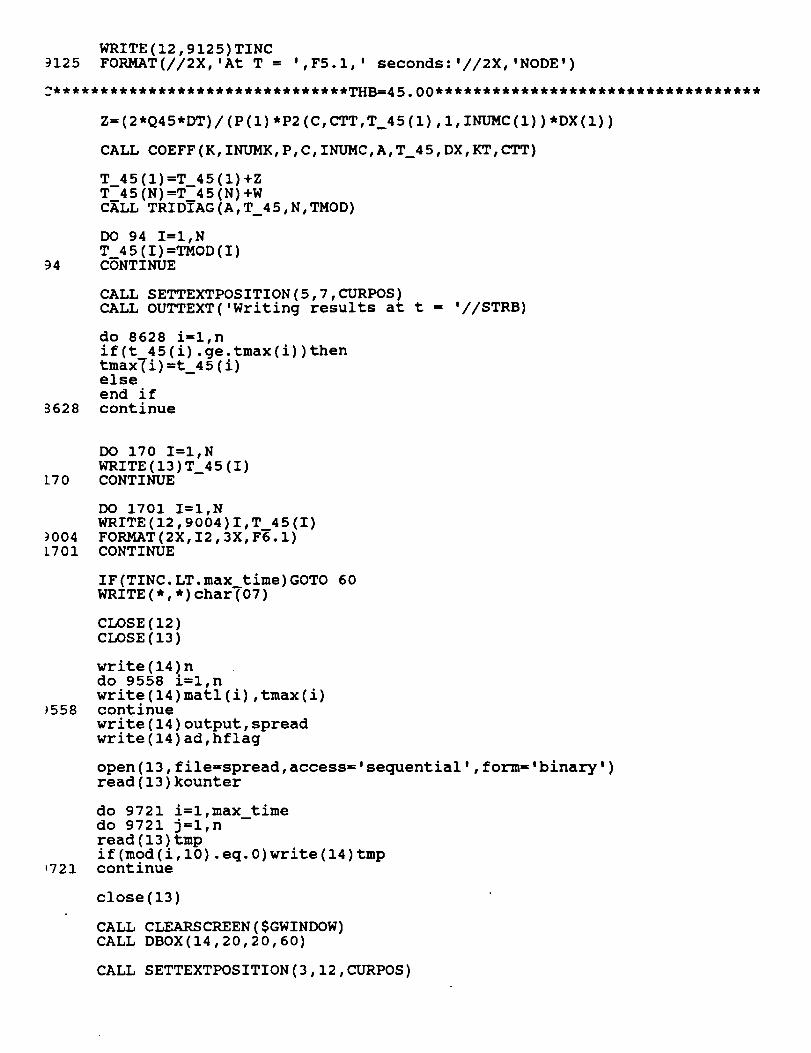
WRITE(12,9125)TINC3125 FORMAT(//2X,'At T = ',F5.1,' seconds:'//2X,'NODE')
Z= (2*Q45*DT) / (P(1) *P2 (C, CTT, T_45 (i), i, INUMC (i)) *DX (i))
CALL COEFF(K,INUMK,P,C,INUMC,A,T_45,DX,KT,CTT)
T 45(I)=T 45(I)+Z
T 45(N)=T 45(N)+W
CALL TRIDIAG (A, T_45, N, TMOD)
94
DO 94 I=I,NT 45 (I) =TMOD (I)CONTINUE
CALL SETTEXTPOSITION(5,7,CURPOS)CALL OUTTEXT('Writing results at t = '//STRB)
3628
do 8628 i=l,n
if(t_45(i).ge.tmax(i))then
tmax(i)=t_45(i)else
end if
continue
170
9004
[701
_558
,721
DO 170 I=I,N
WRITE (13) T__45 (I)CONTINUE
DO 1701 I=I,N
WRITE (12,9004) I,T__45 (I)
FORMAT(2X, I2,3X, F6.1)CONTINUE
IF (TINC. LT. max time) GOTO 60WRITE (*, *) char_07 )
CLOSE(12)CLOSE(13)
write(14)n
do 9558 i=l,nwrite(14)matl(i),tmax(i)continue
write(14)output,spread
write(14)ad,hflag
open(13,file=spread,access='sequential', form='binary')
read(13)kounter
do 9721 i=l,max_timedo 9721 j=l,n
read(13)tmpif(mod(i,10).eq.0)write(14)tmpcontinue
close (13)
CALL CLEARSCREEN ($GWINDOW)CALL DBOX(14,20,20,60)
CALL SETTEXTPOSITION(3,12,CURPOS)

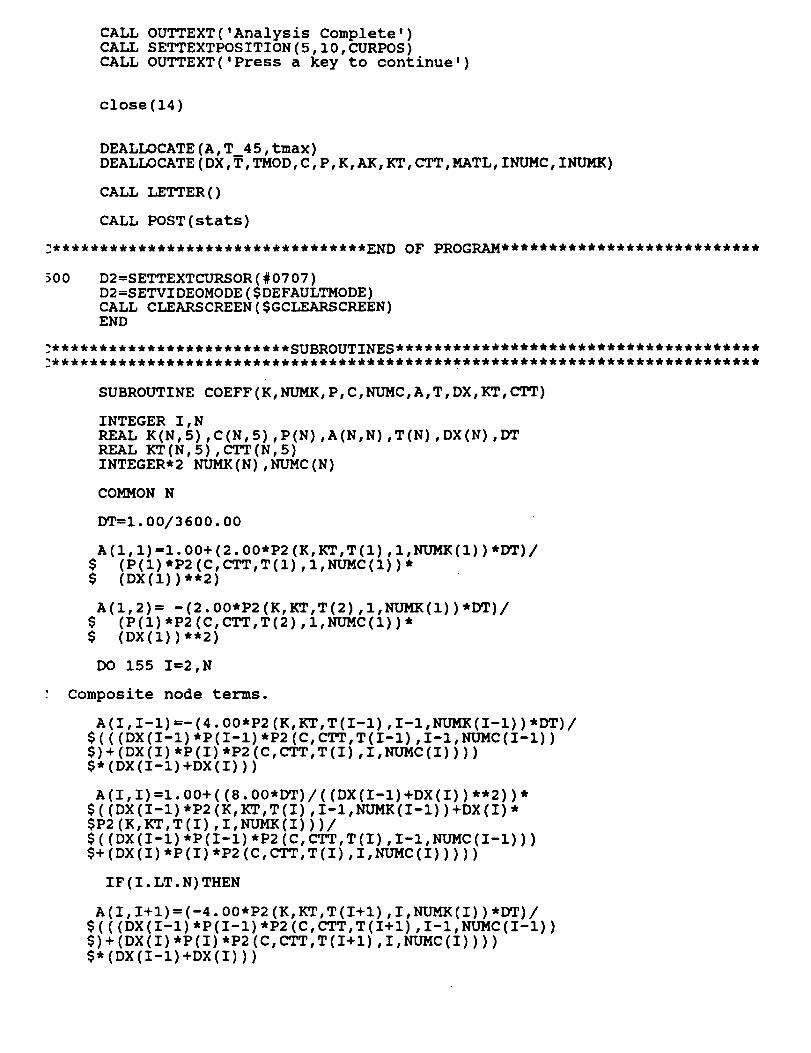
CALL
CALL
CALL
OUTTEXT('Analysis Complete')
SETTEXTPOSITION(5,10,CURPOS)
OUTTEXT('Press a key to continue')
close(14)
DEALLOCATE(A,T_45,tmax)
DEALLOCATE(DX,T,TMOD,C,P,K,AK,KT,CTT,MATL, INUMC,INUMK)
CALL LETTER ()
CALL POST(stats)
_00 D2=SETTEXTCURSOR(#0707)
D2=SETVIDEOMODE($DEFAULTMODE)
CALL CLEARSCREEN($GCLEARSCREEN)END
SUBROUTINE COEFF(K,NUMK,P,C,NUMC,A,T,DX,KT,CTT)
INTEGER I,N
REAL K(N,5),C(N,5),P(N),A(N,N),T(N),DX(N),DT
REAL KT(N,5),CTT(N,5)
INTEGER*2 NUMK (N), NUMC (N)
COMMON N
DT=I.00/3600.00
A(I, I)=I. 00+(2.00*P2 (K, KT, T (I) , I, NUMK (i)) *DT)/$ (P (i) *P2 (C, CTT, T (I) ,I, NUMC (I)) *
$ (DX (I)) **2)
A(I,2)= -(2.00*P2(K,KT,T(2),I,NUMK(1))*DT)/
$ (P (I) *P2 (C, CTT, T (2), i, NUMC (i)) *
$ (DX (i)) **2)
DO 155 I=2,N
: Composite node terms.
A(I, I-l)--(4.00*P2 (K,KT,T(I-I) ,I-I,NUMK(I-I) ) *DT)/$(( (DX (I-l)*P (I-l)*P2 (C, CTT, T (I-l), I-l, NUMC (I-l))
$) + (DX(I) *P(I) *P2 (C, CTT,T (I), I,NUMC (I)) ) )
$* (DX (I-l) +DX (I)) )
A(I, I)=l. 00+ ((8.00*DT) / ( (DX (I-l)+DX (I)) **2) )*
$ ( (DX (I-l) *P2 (K,KT,T (I), I-1,NUMK(I-1) )+DX (I) *
$P2 (K,KT,T (I) ,I, NUMK(I) ) )/
$ ( (DX (I-l) *P (I-l) *P2 (C, CTT, T (I) ,I-l, NUMC (I-l)) )$+ (DX (I)*P(I)*P2 (C, CTT,T (I), I,NUMC (I)) )) )
IF (I. LT. N) THEN
A(I, I+l)= (-4.00*P2 (K, KT,T (I+l), I, NUMK (I)) *DT)/$ ( ( (DX (I-l) *P (I-l) *P2 (C, CTT, T (I+l), I-l, NUMC (I-l))
$)+ (DX (I) *P(I) *P2 (C, CTT, T (I+l), I, NUMC (I)) ) )
$* (DX (I-l) +DX (I)) )

E_EEND IF
155 CONTINUE
RETURN
END
20
]0
SUBROUTINE TRIDIAG (A, S, N, X)
REAL A(N,N) ,S(N) ,X(N)
INTEGER I,N
DO 20 I=I,N-IA (I+l, I+l)=A (I+l, I+l)-( (A (I+l, I)*A (I, I+l) )/A (I, I) )
S (I+l)=S (I+l)- ( (A(I+I, I) *S (I))/A(I, I) )CONTINUE
X (N)--S (N)/A (N, N)
DO 30 I=N-l,l,-1
X (I) = (S (I) -A(I, I+l) *X (I+l))/A(I, I)CONTINUERETURN
END
INCLUDE
INCLUDE
INCLUDE
include
INCLUDE
include
include
'DBOX.FOR'
'GETSTRNG.FOR'
'GETSS0.FOR'
'isub.for'
'REPEAT.FOR'
'oscreen.for'
'post.for'

subroutine post(filename)
include 'fgraph.fd'
integer*2 d2,udpos,udinc,oldudcharacter*30 filename
character*27 option(4)
character*50 narr(4)
record/rccoord/curpos
common/narr/option
option(1)='Quick Summary of Results'option(2)='View Analysis Results'
option(3)='Review a Previous Analysis'
option(4)='Exit Program'
narr(1)='Max/min temperatures, model composition, etc.'
narr(2)='View temperature vs. time graph of analysis'
narr(3)='(Reserved for future use)'narr(4)='Exit ASTC and return to DOS'
d2=setactivepage(1)
d2=settextcursor(#2000)
d2=setbkcolor(1)
d2=settextcolor(3)call settextwindow(l,l,25,80)
call clearscreen($GWINDOW)
do 1 i=2,24
call settextposition(i,2,curpos)
do i j=2,78call outtext(char(177))continue
d2=settextcolor(14)call settextposition(25,12,curpos)call outtext('ASTC V4.0 - Developed by Southern Researc_ Institute
$, 1992')
d2=setbkcolor(3)
d2=settextcolor(1)
call settextwindow(3,25,5,55)
call clearscreen($GWINDOW)
call sbox(3,25,5,55)
call settextposition(2,7,curpos)call outtext('ASTC Post-Processor')
d2=setbkcolor(1)
d2=settextcolor(14)
call settextwindow(7,18,18,62)
call clearscreen($GWINDOW)
call dbox(7,18,18,62)
call settextposition(2,6,curpos)call outtext('Select one of the following options')
call settextposition(3,2,curpos)
call outtext(char(199))
do 2 i=3,43
call outtext(char(196))continue
call outtext(char(182))
do 3 i=i,4

call settextposition(4+i,10,curpos)call outtext(option(i)(l:len_trim(option(i))))continue
call settextposition(10,2,curpos)call outtext(char(199))do 4 i=3,43
call outtext(char(196))continue
call
callcall
outtext(char(182))
settextposition(ll,9,curpos)outtext(char(24)//char(25)//' to move, ENTER to select')
d2=setbkcolor(3)d2=settextcolor(1)call settextwindow(20,12,22,68)call clearscreen($GWINDOW)call sbox(20,12,22,68)
callcallcallcall
settextwindow(21,14,21,66)clearscreen($GWINDOW)settextposition(2,27-(len trim(narr(1)))/2,curpos)outtext(narr(1) (l:len_trim(narr(1))))
d2=setbkcolor(7)d2=settextcolor(1)call settextwindow(11,26,11,55)call clearscreen($GWINDOW)call settextposition(1,2,curpos)call outtext(option(1)(l:len_trim(option(1))))
d2 =setvisualpage (1 )
udinc=0
udpos=loldud=l
do while(udinc.lt.5)call ud(udinc)
if(udinc.eq.5)thenif(udpos.eq.l)thend2=setvisualpage(5)call summary(filename)udinc=0
cycleelseend if
if(udpos.eq.2)thencall plot(filename)udinc=0
cycleelseend if
if(udpos.eq.3)thenudinc=0
cycleelseend if
if(udpos.eq.4)call quit()else

end if
oldud=udpos
udpos=udpos+udinc
if(udpos.gt.4)udpos=l
if(udpos.lt.l)udpos=4
d2=setbkcolor(1)
d2=settextcolor(14)
call settextwindow(10+oldud,26,10+oldud,55)
call clearscreen($GWINDOW)
call settextposition(l,2,curpos)
call outtext(option(oldud)(l:len_trim(option(oldud))))
d2=setbkcolor(7)
d2=settextcolor(1)
call settextwindow(10+udpos,26,10+udpos,55)call clearscreen($GWINDOW)
call settextposition(l,2,curpos)
call outtext(option(udpos)(l:len_trim(option(udpos))))
d2=setbkcolor(3)d2=settextcolor(1)
call settextwindow(21,14,21,66)
call clearscreen($GWINDOW)
call settextposition(2,27-(len trim(narr(udpos)))/2,curpos)call outtext(narr(udpos) (l:len_trim(narr(udpos))))
: read (*, *)
end do
d2=setvideomode($DEFAULTMODE)end
****************************************************
subroutine summary(filename)
include 'fgraph.fd'
00
real tmax[allocatable](:),adinteger*2 d2,hflag
integer ncharacter*8 strf
character*2 stri
character*4 hfl
character*30 filename,opfile,matl[allocatable](:),spreadrecord/rccoord/curpos
open(14,file=filename,access='sequential,,form=,binary,)
read(14)n
allocate(matl(n),tmax(n))do 500 i=l,n
read(14)matl(i),tmax(i)continue
read(14)opfile,spread
read(14)ad,hflag
if(hflag.eq.l)hfl='ASRM'
if(hflag.eq.0)hfl='SSRM'
d2=setactivepage(2)
d2=setbkcolor(1)
d2=settextcolor(3)
call settextwindow(l,l,25,80)

1
call clearscreen($GWINDOW)
do 1 i=2,24
call settextposition(i,2,curpos)do 1 j=2,79call outtext(char(177))continue
d2=settextcolor(14)call settextposition(25,12,curpos)call outtext('ASTC V4.0 - Developed
$, 1992')by Southern Research Institute
callcallcall
settextwindow(4,6,22,74)clearscreen($GWINDOW)dbox(4,6,22,74)
call settextposition(2,25,curpos)call outtext('Summary of Results')
call settextposition(3,2,curpos)call outtext(char(199))do 2 i=1,65call outtext(char(196))continue
call outtext(char(182))
call settextposition(4,4,curpos)call outtext(char(218))do 3 i=i,61call outtext(char(196))continue
call outtext(char(191))
callcall
STemp
settextposition(5,6,curpos)outtext('Layer Material_R')
call settextposition(5,4,curpos)call outtext(char(179))call settextposition(5,66,curpos)call outtext(char(179))
call settextposition(6,4,curpos)call outtext(char(195))do 4 i=1,61call outtext(char(196))continue
call outtext(char(180))
do 5 i=1,6
call settextposition(6+i,4,curpos)call outtext(char(179))call settextposition(6+i,66,curpos)call outtext(char(179))continue
call settextposition(13,4,curpos)call outtext(char(192))
do 6 i=1,61
call outtext(char(196))continue
call outtext(char(217))
Max
call settextposition(4,12,curpos)

call outtext(char(194))
call settextposition(5,12,curpos)
call outtext(char(179)lcall settextposition(6 12,curpos)call outtext(char(193))
:0
call
call
call
call
callcall
settextposition(4,53,curpos)
outtext(char(194))
settextposition(5,53,curpos)
outtext(char(179))settextposition(6,53,curpos)
outtext(char(193))
call
call
call
callcall
call
call
call
settextposition(14,8,curpos)outtext('Areal Density (ib/ft_):')
settextposition(15,8,curpos)
outtext('Heat flux curves used:')
settextposition!16,8,curpos)outtext('Analysls output file:')
settextpositionIl7,8,curpos)outtext('Analysls database file:')
d2=settextcolor(15)
do 20 i=l,n
write(stri,'(i2)')iwrite(strf,'(f7.1)') (tmax(i)+459.60)
call settextposition(6+i,7,curpos)call outtext(stri//' '//marl(i)//'continue
call settextposition(14,33,curpos)write(strf,'(f7.1)')ad
do 25 i=l,len trim(strf)if(strf(i:i).ne.' ')callcontinue
outtext(strf(i:i))
'//strf)
call settextposition(15,31,curpos)
call outtext(hfl)
call settextposition(16,30,curpos)call outtext(opfile)
call settextposition(17,33,curpos)call outtext(spread)
d2=setvisualpage(2)
close(14)
deallocate(tmax,matl)
call letter()
d2=setactivepage(1)d2=setvisualpage(1)
return
end
subroutine plot(filename)
include 'fgraph.fd'
real temp[allocatable](:,:),bs,maxtemp

integer*2 d2,char_flag,hflag,yinc,color(8),xstep,ntempinteger ncharacter*50 str
character*30 filename,bstring,dfile,list,matl[allocatable](:)character*3 xstringcharacter*5 ystring
record/xycoord/xy
record/rccoord/curpos
if(setvideomode($ERESCOLOR).eq.0)then
call clearscreen($GCLEARSCREEN)
print*,'Unable to set EGA graphicsprint*,'Press a key to continue'
else
end if
mode'
if(registerfonts('*.FON').it.0)then
d2=setvideomode($DEFAULTMODE)
print*,' 'print*,'Could not locate font files.
print*,' ''.FON'' extension from the
print*,'the working
print*,'Press a key
call letter()
call reset_screen()returnelse
end if
Copy all files with a'distribution disk into'
directory for this program.'to continue...'
col or (i) =2
color (2) =4col or (3 )=5
color (4 )=6
color (5) =9
color (6) =10color (7 )=3
color (8) =I
open(6,file=filename,access='sequential', form='binary')read(6)n
allocate (matl (n))
do 1 i=l,n
if (i. eq. i) then.
read (6) matl (i) ,maxtempelse
read (6) matl (i) ,bsend if
continue
read(6)bstring,dfile
read(6)x,hflag
maxtemp=maxtemp+459.60
d2=setactivepage(1)
list="t'helv'"//'hl5wl2b'
d2=setfont(list)
call moveto(240,10,xy)
str='Temperature vs. Time'

d2=setcolor(4)
d2=settextcolorI4 )call settextposltion(2,40-1en_trim(str)/2,curpos)call outgtext(str)
d2=setbkcolor($WHITE)d2=setcolor(1)d2=settextcolor(12)call moveto(60,30,xy)d2=lineto(610,30)d2=lineto(610,320)d2=lineto(60,320)d2=lineto(60,30)
d2=settextcolor(1)
call settextposition(25,35,curpos)call outtext('Time (sec)')
call settextposition(1,2,curpos)call outtext('Temp (_R)')
list="t'helv'"//'hlOw8b'd2=setfont(list)
if(hflag.eq.1) thentmax=450
xstep=int2(550/45)icount=45
call moveto(60,325,xy)call outgtext('0')
do 2 i=1,9
call moveto(50+(61*i) ,325,xy)write (xstring, '(i3) ')int (50-i)call outgtext(xstring)continue
else if(hflag.eq.0)thentmax=400
xstep=int2(550/40)icount=40
call moveto(60,325,xy)call outgtext('0')
call moveto(50,325,xy)do 3 i=1,8
call moveto(50+(69*i),325,xy)write(xstring,'(i3)')int(50*i)call outgtext(xstring)continue
elseend if
yinc=int2(maxtemp/10)call moveto(40,315,xy)call outgtext('0')
do 4 i=l,10
write(ystring,'(i5)')int(yinc*i)call moveto(20,315-(i*29),_l)call outgtext(ystring)continue
nt emp= int2 (tmax/10 )

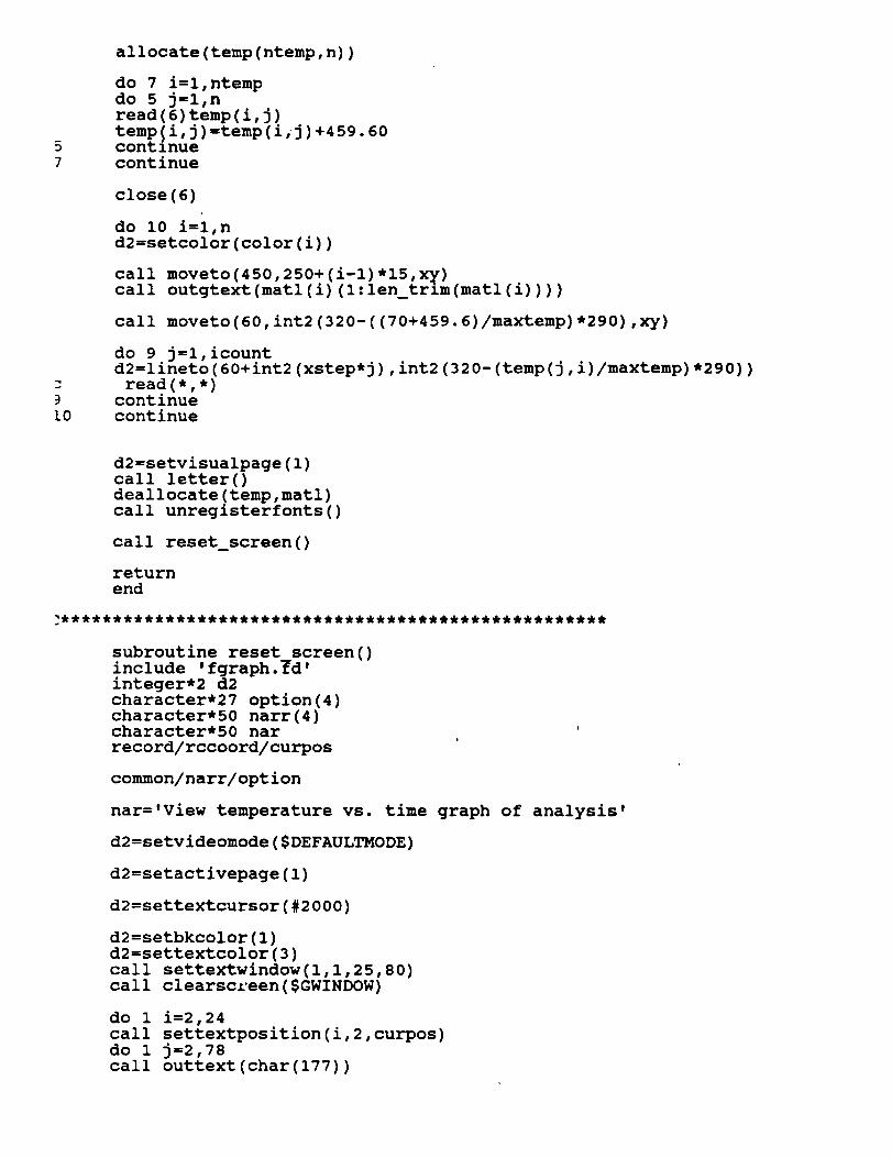
I0
allocate (temp (ntemp, n) )
do 7 i=l,ntemp
do 5 j=l,n
read(6)temp(i,j)
temp(i,j)=temp(i,j)+459.60continue
continue
close(6)
do i0 i=l,n
d2=setcolor(color(i))
call moveto(450,250+(i-l)*lS,xy)call outgtext(matl(i)(l:len_trim(matl(i))))
call moveto(60,int2(320-((70+459.6)/maxtemp)*290),xy)
do 9 j=l,icount
d2=lineto(60+int2(xstep*j),int2(320-(temp(j,i)/maxtemp)*290))
read(*,*)continue
continue
d2=setvisualpage(1)
call letter()deallocate(temp,matl)
call unregisterfonts()
call reset_screen()
return
end
subroutine reset_screen()
include 'fgraph.fd'integer*2 d2
character*27 option(4)character*50 narr(4)character*50 nar
record/rccoord/curpos
common/narr/option
nar='View temperature vs. time
d2=setvideomode($DEFAULTMODE)
d2=setactivepage(1)
graph of analysis'
d2=settextcursor(#2000)
d2=setbkcolor(1)
d2=settextcolor(3)
call settextwindow(l,l,25,80)
call clearscreen($GWINDOW)
do 1
call
do 1
call
i=2,24
settextposition(i,2,curpos)
j=2,78
outtext(char(177))

continue
d2=settextcolor(14)
call settextposition(25,12,curpos)call outtext('ASTC V4.0 - Developed
$, 1992')by Southern Research Institute
d2=setbkcolor(3)d2=settextcolor(1)
call settextwindow(3,25,5,55)call clearscreen($GWINDOW)call sbox(3,25,5,55)call settextposition(2,7,curpos)call outtext('ASTC Post-Processor')
d2=setbkcolor(1)d2=settextcolor(14)call settextwindow(7,18,18,62)call clearscreen($GWINDOW)call dbox(7,18,18,62)call settextposition(2,6,curpos)call outtext('Select one of the
call settextposition(3,2,curpos)call outtext(char(199))do 2 i=3,43call outtext(char(196))continue
following options')
call outtext(char(182))
do 3 i=1,4
call settextposition(4+i,10,curpos)call outtext(option(i)(l:len_trim(option(i))))continue
call settextposition(10,2,curpos)call outtext(char(199))do 4 i=3,43call outtext(char(196))continue
call outtext(char(182))
call settextposition(11,9,curpos)call outtext(char(24)//char(25)//, to move, ENTER
d2=setbkcolor(3)d2=settextcolor(1)
call settextwindow(20,12,22,68)call clearscreen($GWINDOW)call sbox(20,12,22,68)
callcallcallcall
settextwindow(21,14,21,66)clearscreen($GWINDOW)settextposition(l,27-(len trim(nar))/2,curpos)outtext(nar(l:len_trim(na_)))
d2=setbkcolor(7)d2=settextcolor(1)call settextwindow(12,26,12,55)
call clearscreen($GWINDOW)call settextposition(1,2,curpos)call outtext(option(2)(l:len_trim(option(2))))
to select')
d2=setvisualpage(1)


return
end

SUBROUTINE INTRO()INCLUDE 'FGRAPH.FD'
INTEGER*2 D2,I,JCHARACTER*30 LIST
RECORD/RCCOORD/CURPOS
RECORD/XYCOORD/XY
IF(SETVIDEOMODE($ERESCOLOR).EQ.0)RETURN
IF(REGISTERFONTS('*.FON').LT.0)RETURN
d2=setactivepage(1)
D2=SETTEXTCOLOR(14)
CALL DBOX(I,1,25,80)
CALL SETTEXTPOSITION(3,2,CURPOS)
CALL OUTTEXT(CHAR(199))
DO 5 I=1,76CALL OUTTEXT(CHAR(196))CONTINUE
CALL OUTTEXT(CHAR(182))
L0
CALL SETTEXTPOSITION(23,2,CURPOS)
CALL OUTTEXT(CHAR(199))
DO 10 I=I,76
CALL OUTTEXT(CHAR(196))CONTINUE
CALL OUTTEXT(CHAR(182))
D2=SETCOLOR(7)D2=RECTANGLE($GFILLINTERIOR,71,270,79,282)
D2=SETCOLOR (8)
D2=RECTANGLE($GFILLINTERIOR, 67,250,102,266)
D2=RECTANGLE($GFILLINTERIOR,84,270,102,285)
D2=RECTANGLE($GFILLINTERIOR,47,267,67,282)
D2=RECTANGLE($GFILLINTERIOR,47,285,84,301)
D2=PIE($GFILLINTERIOR, 47,250,87,282, 67,246,47,266)
D2=PIE($GFILLINTERIOR, 66,269,102,301, 84,301 ,102,284)
LIST="t'helv'"//'hl5wl2b'
D2=SETFONT(LIST)
d2=setcolor(7)
CALL MOVETO(120,265,XY)CALL OUTGTEXT('Southern Research Institute')
CALL MOVETO(120,280,XY)
CALL OUTGTEXT('I992')
LIST="t'tms rmn'"//'h30w24b'
D2=SETFONT(LIST)
CALL MOVETO(250,80,XY)
D2 =SETCOLOR (4 )
CALL OUTGTEXT('A S T C')
LIST="t'helv'"//'h20wl2b'
D2=SETFONT(LIST)
d2=SETCOLOR(14)

.'15
CALL MOVETO (100,110, XY)
CALL OUTGTEXT('Aft Skirt Thermal Curtain Analysis Program')
CALL SETTEXTPOSITION (12,34, CURPOS)CALL OUTTEXT( 'Version 4.0' )
d2 =setact ivepage (0 )
d2=setcolor (3 )
DO 15 I=I,175,2
D2 =RECTANGLE ($GFILLINTERIOR, 320-1.8,I, 175-I, 320+1.8.I, 175+7 )CONTINUE
D2=SETBKCOLOR($BLUE)
d2=setvisualpage(1)D2=SETACTIVEPAGE(1)
call delay(int2(300))
CALL SETTEXTPOSITION(15,30,CURPOS)
CALL OUTTEXT('Press a key to begin')
call letter ()call unregisterfonts()
D2=SETVIDEOMODE($DEFAULTMODE)RETURN
END

0
SUBROUTINE REPEAT__MATL (I, N, MATL, KT, AK, CTT, C, P, DX)INCLUDE 'FGRAPH. FD'
INTEGER N,I
REAL KT(N,5),AK(N,5),CTT(N,5),C(N,5),P(N),DX(N)CHARACTER*30 MATL(N)
INTEGER*2 D2,ARPOS,OLDARROW,ARINCCHARACTER*2 $2
CHARACTER YN
RECORD/RCCOORD/CURPOS
D2=SETACTIVEPAGE(1)
D2=SETVISUALPAGE(1)
D2=SETBKCOLOR(1)
D2=SETTEXTCOLOR(15)
CALL SETTEXTWINDOW(I,I,25,80)CALL CLEARSCREEN($GCLEARSCREEN)
CALL DBOX(I,I,25,80)
CALL SETTEXTPOSITION(4,18,CURPOS)
WRITE(S2,'(I2) ')I
CALL OUTTEXT('Select material for blanket layer number '//$2)CALL SETTEXTPOSITION(5,18,curpos)
CALL OUTTEXT('Use arrow keys to move cursor, ENTER to select')
D2=SETBKCOLOR(7)
D2=SETTEXTCOLOR(4)
CALL SETTEXTWINDOW(8,20,11+I,60)
CALL CLEARSCREEN($GWINDOW)CALL DBOX(8,20,12+I,60)
D2 =SETTEXTCOLOR (1 )
DO 10 J=l,I-i
CALL SETTEXTPOSITION(2+J,6,CURPOS)CALL OUTTEXT(MATL(J))CONTINUE
D2=SETBKCOLOR(1)
D2=SETTEXTCOLOR(15)
CALL SETTEXTWINDOW(10,24,10,26+LEN_TRIM(MATL(1)))CALL CLEARSCREEN($GWINDOW)
CALL SETTEXTPOSITION(I,2,CURPOS)
CALL OUTTEXT(MATL(1)(I:LEN_TRIM(MATL(1))))
ARPOS=I
ARINC=0
DO WHILE(ARINC.LT.5)D2=SETBKCOLOR(1)
D2=SETTEXTCOLOR(15)OLDARROW=ARPOS
CALL
CALL
CALL
CALL
SETTEXTWINDOW(9+ARPOS,24,9+ARPOS,26+LEN TRIM(MATL(ARPOS)))CLEARSCREEN($GWINDOW)
SETTEXTPOSITION(1,2,CURPOS)
OUTTEXT(MATL(ARPOS)(I:LEN_TRIM(MATL(ARPOS))))
CALL UD(ARINC)
IF(ARINC.EQ.5)EXITARPOS=ARPOS+ARINC
IF(ARPOS.GT.I-I)ARPOS=I
IF(ARPOS.LT.I)ARPOS=I-I
D2=SETBKCOLOR(7)
D2=SETTEXTCOLOR(1)

CALL SETTEXTWINDOW(9+OLDARROW,24,9+OLDARROW,26+LEN TRIM(MATL(OLDAR$ROW)))
CALL CLEARSCREEN($GWINDOW)CALL SETTEXTPOSITION(I,2,CURPOS)
CALL OUTTEXT(MATL(OLDARROW)(I:LEN_TRIM(MATL(OLDARROW))))END DO
D2 =SETBKCOLOR (4 )
SETTEXTWINDOW(18,15,23,65)
CLEARSCREEN($GWINDOW)
DBOX(18,15,23,65)SETTEXTPOSITION(2,9,CURPOS)
OUTTEXT('Selected material for layer
CALL
CALL
CALLCALL
CALL
CALL
CALL
CALL
CALLCALL
IF(YN.EQ.'N')GOTO i
'lls211' is' )SETTEXTPOSITION(3,9,CURPOS)
OUTTEXT(MATL(ARPOS)(I:LEN_TRIM(MATL(ARPOS)))//'.')
SETTEXTPOSITION(4,9,CURPOS)
OUTTEXT('Is this correct (Y/N)?')
Y OR_N (YN)
_0
MATL (I )=MATL (ARPOS)
DX (I )=DX (ARPOS)P(I) =P (ARPOS)
DO 50 JJ=l,5
CTT(I,JJ)=CTT(ARPOS,JJ)C(I,JJ)=C(ARPOS,JJ)
KT(I,JJ)=KT(ARPOS,JJ)
AK(I,JJ)=AK(ARPOS,JJ)CONTINUE
D2 =SETACTIVEPAGE (0 )
D2=SETVISUALPAGE (0 )RETURN
END

subroutine OSCREEN(n,e,filel,file2,hflag,file3)include 'fgraph.fd'integer*2 d2,ct,hflaginteger ndouble precision xxreal e
character*30 filel,file2,file3character*l a s
record/rccoor_/curpos
d2=setactivepage(1)
d2=setbkcolor(1)d2=settextcolor(3)call clearscreen($GCLEARSCREEN)
do 1 i=2,24call settextposition(i,2,curpos)do 1 j=2,79call outtext(char(177))continue
d2=settextcolor(14)call settextposition(25,12,curpos)call outtext('ASTC V4.0 - Developed by Southern Research Institute
$, 1992')
d2=setbkcolor(3)d2=settextcolor(1)call settextwindow(4,15,6,65)call clearscreen($GWINDOW)call sbox(4,15,6,65)call settextposition(2,10,curpos)call outtext('Input the following information')
d2=setbkcolor(1)d2=settextcolor(15)call settextwindow(9,15,19,65)call clearscreen($GWINDOW)d2=settextcolor(14)call dbox(9,15,19,65)
call settextposition(3,5,curpos)call outtext('Name of output file: ')call settextposition(5,5,curpos)call outtext('Number of blanket layers: ')call settextposition(7,5,curpos)call outtext('Emittance (0 < e < 1): ')call settextposition(9,5,curpos)
call outtext('Heat Flux (ASRM/SSRM): ')d2=settextcolor(15)call settextposition(9,16,curpos)call outtext('A')call settextposition(9,21,curpos)call outtext('S')d2=settextcolor(14)call settextposition(9,26,curpos)
call outtext(':')
d2=setvisualpage(1)
d2=settextcolor(15)call settextposition(3,26,curpos)

_0
L2
5
call getstrng(filel,ct)
call settextposition(5,31,curpos)
if(curpos.col.eq.26)then
write(*,*)char(07)
goto 5elseend if
call getnumf(xx,ct)
n=int2(xx)
if(n.eq.0)thenwrite(*,*)char(07)
goto I0elseend if
call settextposition(7,28,curpos)
if(curpos.col.eq.31.and.n.eq.0)then
write(*,*)char(07)
goto i0else
end if
call getnumf(xx,ct)e=xx
if(e.lt.0.00.or.e.gt.l.00)then
write(*,*)char(07)
goto 12else
end if
call settextposition(9,29,curpos)
if(curpos.col.eq.28)thenwrite(*,*)char(07)
goto 12else
end if
call settextposition(9,30,curpos)
if(curpos.col.eq.28)thenwrite(*,*)char(07)
goto 15else
end if
call getstrng(a_s,ct)
if(a_s.eq.'a'.or.a_s.eq.'A')thenhflag=l
else if(a_s.eq.'s'.or.a_s.eq.'S')then
hflag=0else
write(*,*)char(07)
goto 15end if
0
k=0
do 20 i=l,len trim(filel)
if(filel(i:i)-eq.'.')thenk=i
exit
else
end if
continue
if(k.eq.0)then

file2=filel(l:len trim(filel))//'.dbs.file3=filel(l:lenZtrim(filel))//'.db $,elsefile2=filel(l:k-l)//'.dbs'file3=filel(l:k-l)//'.db$'end if
read(*,*)
d2=setvideomode($DEFAULTMODE)
print*,filel,n,e,a_s,hflagprint*,file2
return
end
include 'sbox.for'

SUBROUTINE GETS80 (NAME, CTRL)INCLUDE 'FGRAPH. FD '
CHARACTER*I X
CHARACTER*80 NAME
INTEGER*2 CTRL,ROW,COL
RECORD/RCCOORD/CURPOS
CTRL=0
I=0
DO WHILE(CTRL.NE. 100)CALL GETKEYF (X, CTRL)
IF (CTRL. EQ. 0) THENI=I+l
NAME (I :I )=XCALL OUTTEXT (X)ELSE
END IF
I F (CTRL. EQ. - 25 )THENIF (I.GT. 0) THEN
NAME (I :I) =' 'I=I-i
CALL GETTEXTPOSITION (CURPOS)COL=CURPOS .COL- 1
ROW=CURPOS. ROW
CALL SETTEXTPOSITION (ROW, COL, CURPOS )
CALL OUTTEXT(' ')CALL SETTEXTPOSITION (ROW, COL, CURPOS)ELSE
END IFELSE
END IF
_0
IF(CTRL.EQ.-50.OR.CTRL.EQ.5)RETURN
END DO
DO 20 K=I+I,80
NAME(K:K)=' 'CONTINUE
RETURN
END

SUBROUTINE GETSTRNG(NAME,CTRL)INCLUDE 'FGRAPH.FD'
CHARACTER*I X
CHARACTER*50 NAME
INTEGER*2 CTRL,ROW,COL
RECORD/RCCOORD/CURPOS
CTRL=0
I=0
DO WHILE(CTRL.NE. I00)
CALL GETKEYF (X, CTRL)
I F (CTRL. EQ. 5 )RETURN
IF (CTRL. EQ. 0) THENI=I+l
NAME (I :I )=XCALL OUTTEXT (X)ELSE
END IF
IF (CTRL. EQ. -25) THEN
IF (I. GT. 0) THEN
NAME (I :I) =' 'I=I-ICALL GETTEXTPOS ITION (CURPOS)
COL=CURPOS .COL-I
ROW-- CURPOS. ROWCALL SETTEXTPOS ITION (ROW, COL, CURPOS )
CALL OUTTEXT(' ')CALL SETTEXTPOSITION (ROW, COL, CURPOS)
ELSEEND IF
ELSE
END IF
IF(CTRL.EQ.-50)RETURN
END DO
0
DO 20 K=I+I,50
NAME(K:K)=' 'CONTINUE
RETURN
END

SUBROUTINEDBOX(XII,YII,X22,Y22)
XI,X2,YI,Y2 ARE THE CORNERS OF THE CURRENT TEXTWINDOW
INCLUDE 'FGRAPH.FD'
INTEGER XII,X22,YII,Y22
INTEGER*2 Xl,X2,YI,Y2
RECORD/RCCOORD/CURPOS
XI=INT2 (XlI)
X2=INT2 (X22)
YI=INT2 (YII)Y2=INT2 (Y22)
CALL SETTEXTPOSITION(I,2,CURPOS)
CALL OUTTEXT (CHAR(201))
DO 5 I=l, (Y2-YI)-3CALL OUTTEXT (CHAR (205) )CONTINUE
CALL OUTTEXT(CHAR(187))
0
DO i0 I=I,(X2-XI)-ICALL SETTEXTPOSITION(I+I,2,CURPOS)
CALL OUTTEXT (CHAR (186.) )CALL SETTEXTPOSITION(I+I,(Y2-YI),CURPOS)
CALL OUTTEXT(CHAR(186))CONTINUE
5
CALL SETTEXTPOSITION((X2-XI)+I,2,CURPOS)
CALL OUTTEXT(CHAR(200))
DO 15 I=I,(Y2-YI)-3CALL OUTTEXT(CHAR(205))CONTINUE
CALL OUTTEXT(CHAR(188))
RETURN
END

N SAfLD* d_ltem .Btl
• I*iolr _ e**_
I. 14mNwt Nn.
Final
Title _ Su_W.
%
Report Documentation Page
-_2. r.,_,,mmentA=,m_ No.
SRB Thermal Curtain
Design Support
•_. ;L,m_o,,,)Carl A. Dixon
Wayne E. LundbladJohn R. Koenig
0. _om_.90r(pm=at_ Name o_ Address
Southern Research Institute
2000 9th Avenue South
Birmingham, AL 35255
i2. _x;,T.q A_ Name._ _=,."BP Chemicals (Hitco) Inc.Fibers & Materials Division
700 E. Dyer Road
Santa Ana, CA 92705
lk"._;l_,_.,,=,a,'r No,.
3. P,w.k:,ent's Ceu=lo9 No.
5. Report D4ne
November 1992
S. Perlormm_ Orgomzatmn Code
27129
8. _'e,':,;,,-;r,_,';_Or0anLzatmon n_(Wt No.
• Final
10. Wmt Unit No.
11. Contract or Grant NO.
NAS8-38261
13. Type of Report ar__ P_.,od LC_'_ 1Final Tecnnzca
2/16/90 - 2/28/93
14. Sponsor_ A_ncyCode
AP48D
16. At_.;_a
Improvements in SRB Thermal Curtain were identified by Thermal
Design featuring:
a)
b)
o
c)
• I
selection of materials capable of thermal protection (insulatzon)_
and service temperatures by tri-layering, quartz, $2 glass/
Kevlar, in thinner (lighter) cross section !
weaving in single piece (instead of 24 sections) to achieve
fmproved strength (resist aero loads)
weaving to reduce mfg. (labor) cost with angle interlock
construction
7. K_V _,.,t_ (SUtI_S 1_ I)V AuIN)f(5))
t
Quartz S- Glass & Kevlar Fibers
Angle Interlock & Polar Weave
18. Distribution Statement
• ;9 :;..... ,vO.,..d ',,'th,.,.,ram...... _ _:-_cu,,ty C_.d (o!m,$ =mee, i21• NO O| pg_
i 1., Unclassified Un¢Ip_sified 142
NASA FORM 1&,_ OCI It%For sale by the Natlonal Technical Informatlon Service, Springfield, VA
I _ Pr,c*:
I
22161-2171

rl:_ '̧:i::'
i ' \If "i I/ ' ....
/ \/