US ARmy Corps of Engineers - Structural Inspection of Existi
53
DEPARTMENT OF THE ARMY ETL 1110-2-346 U.S. Army Corps of Engineers CECW-ED Wash ing ton, DC 20314-1000 Technical Letter No. 1110-2-346 30 September 1993 Engineering and Design STRUCTURAL INSPECTION AND EVALUATION OF EXISTING WELDED LOCK GATES 1. Pur pose This engineer technical letter (ETL) provides guidance for evaluating the structural adequacy of existing welded lock gates. 2. Applica bility This ETL applies to HQUSACE elements, major subordinate commands, districts, laboratories, and field operating activities having responsibilities for civil works projects. 3. Ref erences a. ER 1110-2- 100, Peri odic Insp ecti on and Continuing Evaluation of Completed Civil Works Structures. b. ER 1110-2- 101, Repor ting Evid ence of Dis- tress of Civil Works Projects. c. EM 1110-2 -2105 , Design of Hydrau lic Stee l Structures. d . EM 1110-2 -2703 , Lock Gates and Op erati ng Equipment. 4. Discussion a. ER 1110-2-1 00 defines peri odic inspe ction requirements for completed civil works projects. These requirements include all aspects of a project and are gener al in nature . ER 1110-2- 101 requi res that signs of distress in any project feature be repor ted throu gh channel s to HQUSACE. Neith er of these references describes how to perform a detailed inspection and evaluation of hydraulic steel structures. b. The st ate of the ar t in metal fa tig ue and fracture analysis has advanced greatly in recent years . In many indust ries thes e concepts are regu - larly applied to new designs and to evaluation of exist ing structu ral elemen ts. EM 1110-2-2105 requires that fatigue and fracture be considered when designing new hydraulic steel structures. c. Steel str uctur es at severa l civil work s pro- ject s have experienced sever e cracking . Some of these inc ident s are discusse d in Enclosure 1. This demonstrates the need to emphasize fatigue and fracture concepts when inspecting and evaluating such structures. d . The six enc losur es to this ETL pro vide detailed methods for inspection and evaluation of existing steel lock gates. These enclosures provide specific recommendations for inspection techniques, evaluation of detected flaws, and prediction of rema ining life . These conce pts are also applica ble to a wide range of other structures, including almost any steel structure in a civil works project. 5. Acti on a. Peri odic insp ecti on of steel lock gat es should include close visual inspection of critical members and connections.
Transcript of US ARmy Corps of Engineers - Structural Inspection of Existi

8/6/2019 US ARmy Corps of Engineers - Structural Inspection of Existi
http://slidepdf.com/reader/full/us-army-corps-of-engineers-structural-inspection-of-existi 1/53
DEPARTMENT OF THE ARMY ETL 1110-2-346U.S. Army Corps of Engineers
CECW-ED Washington, DC 20314-1000
TechnicalLetter No. 1110-2-346 30 September 1993
Engineering and DesignSTRUCTURAL INSPECTION AND EVALUATION
OF EXISTING WELDED LOCK GATES
1. Purpose
This engineer technical letter (ETL) provides
guidance for evaluating the structural adequacy of
existing welded lock gates.
2. Applicability
This ETL applies to HQUSACE elements, major
subordinate commands, districts, laboratories, and
field operating activities having responsibilities for
civil works projects.
3. References
a. ER 1110-2-100, Periodic Inspection andContinuing Evaluation of Completed Civil Works
Structures.
b. ER 1110-2-101, Reporting Evidence of Dis-
tress of Civil Works Projects.
c. EM 1110-2-2105, Design of Hydraulic Steel
Structures.
d . EM 1110-2-2703, Lock Gates and Operating
Equipment.
4. Discussion
a. ER 1110-2-100 defines periodic inspection
requirements for completed civil works projects.
These requirements include all aspects of a project
and are general in nature. ER 1110-2-101 requires
that signs of distress in any project feature be
reported through channels to HQUSACE. Neither
of these references describes how to perform a
detailed inspection and evaluation of hydraulic steel
structures.
b. The state of the art in metal fatigue and
fracture analysis has advanced greatly in recent
years. In many industries these concepts are regu-
larly applied to new designs and to evaluation of
existing structural elements. EM 1110-2-2105
requires that fatigue and fracture be considered
when designing new hydraulic steel structures.
c. Steel structures at several civil works pro-
jects have experienced severe cracking. Some of
these incidents are discussed in Enclosure 1. This
demonstrates the need to emphasize fatigue andfracture concepts when inspecting and evaluating
such structures.
d . The six enclosures to this ETL provide
detailed methods for inspection and evaluation of
existing steel lock gates. These enclosures provide
specific recommendations for inspection techniques,
evaluation of detected flaws, and prediction of
remaining life. These concepts are also applicable
to a wide range of other structures, including almost
any steel structure in a civil works project.
5. Action
a. Periodic inspection of steel lock gates
should include close visual inspection of critical
members and connections.

8/6/2019 US ARmy Corps of Engineers - Structural Inspection of Existi
http://slidepdf.com/reader/full/us-army-corps-of-engineers-structural-inspection-of-existi 2/53
ETL 1110-2-34630 Sep 93
b. If cracks are detected during periodic
inspections, the cracked elements and other critical
locations should be evaluated using the methods
defined in the enclosure.
c. These actions should also be implemented
for other steel features of civil works projects when
deemed appropriate by the structural engineer.
FOR THE DIRECTOR OF CIVIL WORKS:
6 Encl PAUL D. BARBER, P.E.
Chief, Engineering Division
Directorate of Civil Works
2

8/6/2019 US ARmy Corps of Engineers - Structural Inspection of Existi
http://slidepdf.com/reader/full/us-army-corps-of-engineers-structural-inspection-of-existi 3/53
ETL 1110-2-34630 Sep 93
GENERAL DISCUSSION
1. Scope
a. Enclosures 1 through 6 include procedures to
inspect existing welded steel lock gates and evaluatethem for potential failure. The general concepts
may also be applied to new designs, riveted and
bolted gates, gates for other purposes, and even to
other types of materials.
b. This enclosure provides general discussion
and Enclosure 2 discusses causes of structural dete-
rioration. Enclosure 3 describes the level of steel
gate inspection appropriate during a periodic inspec-
tion. This includes preselecting critical locations
which require close examination, including identifi-
cation of fracture critical members and connections
and visual inspection. Enclosure 4 describes the
detailed nondestructive testing procedures which
should be used while performing a detailed struc-
tural inspection. Some of these procedures may
also be appropriate during periodic inspections.
c. When evaluating older lock gates, necessary
material information may not be available. It may
become necessary to perform material testing to
determine the chemistry, strength, ductility, hard-
ness, and toughness of the base and weld metal.
For this reason, material and weld testing tech-
niques are discussed in detail in Enclosure 5.
d. Engineering evaluation of an existing gate
should be more than an educated guess or a subjec-
tive evaluation. The gate condition should be deter-
mined numerically using proper fatigue and fracture
analysis methods. These procedures are described
in Enclosure 6. The analyses can be used to deter-
mine if the gate is safe to continue current
operation, what is a safe interval until the next
inspection, and what is the remaining life of the
gate for expected operating conditions.
2. Types of Gates
a. Currently, the U.S. Army Corps of Engineers
(USACE) operates over 250 lock chambers. The
functional requirements for lock gates vary, depend-
ing on the specific project location and operating
conditions. The primary purpose for steel gates is
to provide a damming surface across the lock
chamber; however, they can also be used as guard
gates, valves for filling and emptying the lock
chamber, for passing ice and debris, to unwater the
lock chamber, to separate salt and fresh water, andto provide access from one lock wall to the other
via walkways attached to the top of the gates. Most
existing lock gates are miter gates and vertical-lift
gates, with a small percentage being sector gates
and submergible tainter gates.
b. The majority of lock gates are of the miter
type, primarily because they tend to be more eco-
nomical to construct and operate and can be opened
and closed more rapidly than other types of lock
gates. Miter gates are categorized by their framing
mechanism into vertically or horizontally framed
gates. Water pressure acting on the skin plate of a
vertically framed gate is resisted by vertical beam
members supported by a horizontal girder at the top
and bottom of the leaf. The horizontal girders then
transmit the loads to the miter and quoin at the top
of the leaf and into the sill at the bottom of the leaf.
Horizontally framed lock gates transmit the skin
plate water load directly to horizontal girders which
then transfer the load to the quoin block and into
the walls of the lock monolith. Current design
guidance, Engineer Manual (EM) 1110-2-2703,
"Lock Gates and Operating Equipment,"1 recom-
mends that future miter gates be horizontallyframed; however, a large percentage of existing
miter gates are vertically framed.
c. Another type of lock gate is the sector gate.
This gate is framed similar to a tainter gate, how-
ever, it pivots about a vertical axis similar to a
miter gate. Sector gates have traditionally been
used in tidal reaches of rivers or canals and conse-
quently may be subject to head reversal. Sector
gates may be used to control flow in the lock cham-
ber during normal operation or close off flow dur-
ing emergency operation. Sector gates are generally
limited to lifts of 10 ft or less.
d. Vertical-lift gates differ from miter and
sector gates in that they are raised and lowered
____________________1 References for Enclosures 1 through 6 are found
in the Reference section following Enclosure 6.
Enclosure 1 1-1

8/6/2019 US ARmy Corps of Engineers - Structural Inspection of Existi
http://slidepdf.com/reader/full/us-army-corps-of-engineers-structural-inspection-of-existi 4/53
ETL 1110-2-34630 Sep 93
vertically to open or close the lock chamber. The
load developed by water pressure acting on the lift
gate skin plate is transmitted along horizontal
girders into the walls of the lock monolith. Lift
gates can be operated under moderate heads but not
under reverse head conditions.
e. Submergible tainter gates are used infre-
quently as lock gates. This type of gate pivots
similar to a spillway tainter gate but is raised to
close the lock chamber and lowered into the cham-
ber to open it. The load developed by water pres-
sure acting on the submergible tainter gate skin
plate is transmitted along horizontal girders to struts
recessed in the lock wall. The struts are connected
to and rotate about trunnions anchored to each lock
wall.
3. Strength and Serviceability Requirements
a. Lock gates are designed according to
requirements of appropriate EM’s and design codes
as listed in EM 1110-2-2105, "Design of Hydraulic
Steel Structures." Lock gates are designed to have
design strengths at all sections equal, at least, to the
required strengths calculated for the critical combi-
nation of loads and forces. Various gate members
must be designed to resist axial forces, bending
forces, and combined bending and axial forces.
These members are fabricated from bars, plates,
standard rolled shapes, and built-up sections
depending on geometrical requirements, loading,and economics. Structural inspection and evalua-
tion are required to assure that adequate strength
and serviceability are maintained at all sections
during the life of the gate.
b. Serviceability is a state in which the function
of a lock gate, its maintainability, durability, and
operability are preserved for the life of the gate.
The structural inspection and evaluation must assure
that all deflections, deformations, vibrations, corro-
sion, and wear of structural members do not impair
the operability or performance of the lock gate.
4. Examples of Distressed Lock Gates
Fracture and failure of steel members and connec-
tions have occurred in several Corps of Engineers
projects. These projects received the required peri-
odic inspections. However, the inspections were
not detailed enough to detect initial cracks nor were
fatigue and fracture analyses performed for these
structures prior to, and often not subsequent to,
failure. The following brief examples, all taken
from a single district, illustrate the potential results
of casual inspection combined with inattention to
fatigue and fracture concepts during design.
a. Miter gate anchorage.
(1) The project utilized vertically framed
downstream miter gates, 45 ft high, with a 110-ft
lock width. The upper embedded gate anchorage
failed unexpectedly while the chamber was at tail-
water elevation. Failure occurred by fracture at the
gudgeon pin hole. The anchor was a structural steel
assembly of two channels and two 1/2-in.-thick
plates. The use of a channel with up-turned legs
causes ponding of water and results in pitting and
scaling corrosion. Since the anchor is a nonredun-dant tension member, failure caused the leaf to fall
to the concrete sill, though it remained vertical.
(2) The failure surfaces were disposed of
without an examination to determine the cause of
failure. To make the lock operational as quickly as
possible, repairs were implemented without any
evaluation or recommendations from the Engineer-
ing Division. These repairs consisted of butting and
welding a new channel section to the remaining
embedded section and bolting a 1-in. cover plate to
the channel webs. The bolt and plate materials are
not known.
(3) The same type of anchorage is used on at
least two other projects with a total of 16 similar
anchors.
b. Spare miter gate.
(1) The project had a spare miter gate which
consisted of five welded modules. When in use,
these modules were stacked vertically and bolted
together. The spare gate had been used several
times. However, 1 month after the last installation,
cracks were discovered in the downstream flanges
of three vertical girders. The cracks originated at
the downstream face of the flange in the heat
affected zone at the toe of a transverse fillet weld.
(This detail is category E for fatigue design.) The
cracks then propagated through the flange and into
the web. After cracking the downstream face of the
flanges was 0.5-in. out-of-vertical alignment.
1-2

8/6/2019 US ARmy Corps of Engineers - Structural Inspection of Existi
http://slidepdf.com/reader/full/us-army-corps-of-engineers-structural-inspection-of-existi 5/53
ETL 1110-2-34630 Sep 93
(2) Quick repairs were performed by operations
personnel, without input from engineering person-
nel. The web crack was filled with weld. The
flange cracks were gouged and welded, then two
small bars were fillet welded across the crack. The
bar material is unknown. These repairs served to
get the gate back into service immediately. How-ever, reliable long-term repairs also should be
developed and implemented.
c. Submersible lift gate.
(1) This project has a submersible lift gate as
the main, operational, upstream lock gate. The gate
consists of two leaves with six horizontal girders
spanning 110 ft. Several cracks were discovered in
one leaf while the lock was out of service for other
repairs. Subsequent detailed inspection identified
over 100 cracks in girder flanges and bracing mem-
bers. One crack extended through the downstreamflange of a horizontal girder and 3 ft into the
8-ft-deep web.
(2) This gate was subjected to a detailed inves-
tigation of the cause of the cracking. The study
identified several contributing factors: the original
design had ignored a loading case and had included
improper loading assumptions; limit switches were
improperly stopping the gate before it reached its
supports; the design ignored higher stresses caused
by eccentric connections on the downstream face;
most of the original welds did not meet current
American Welding Society (AWS) quality stan-dards; the steel for the gate had a low fracture
toughness, ranging from 5 ft-lb at 32 oF to 15 ft-lb
at 70 oF.
(3) Repair procedures were designed by engi-
neering personnel for this gate. However, the
specified weld procedures were not used by the
contractor, and the welders were not properly quali-
fied per AWS requirements. These facts may have
caused inadequate repair welds, which duplicates
part of the causes of the original cracking problem.
5. Summary
The preceding examples represent only a few of the
steel cracking problems which have occurred on
Corps of Engineers projects. It is evident that steel
fatigue and fracture are real problems. Engineering,
construction, and operations personnel should be
aware of this and of the preventive procedures
needed to minimize such problems. Prevention is
best accomplished through proper design and con-
struction, followed by adequate maintenance andinspection. However, many existing steel structures
may be susceptible to fatigue and fracture problems.
When cracks are discovered, engineering personnel
should evaluate the reliability or remaining life of
the structure, determine the need for repairs, and
develop adequate repair plans. When fractures
occur, operations and engineering personnel should
work together to investigate the causes and develop
reliable repair plans. Enclosures 2 through 6 pre-
sent methods for inspection and evaluation of exist-
ing steel lock gates. These procedures should be
followed to identify and correct deficiencies before
they result in serious failures.
1-3

8/6/2019 US ARmy Corps of Engineers - Structural Inspection of Existi
http://slidepdf.com/reader/full/us-army-corps-of-engineers-structural-inspection-of-existi 6/53
ETL 1110-2-34630 Sep 93
CAUSES OF DETERIORATION
1. Corrosion
Corrosion is degradation of a material by reaction
with its environment. All corrosion processes haveelectrochemical reactions as their bases. Some are
purely electrochemical, such as galvanic, pitting,
crevice, and general corrosion, whereas others result
from the action of chemical plus mechanical factors,
such as erosion and stress corrosion.
a. General corrosion is characterized by an
uniform attack over the entire exposed surface with
minimal variation in the depth of damage. The rate
of attack is usually predictable, and catastrophic
failure does not often result. Galvanic corrosion
occurs when two or more dissimilar metals are in
contact and placed in an electrolyte such as water.
A potential difference in the metals causes a flow
of current between them, and the more active metal
(anode) undergoes accelerated corrosion whereas
corrosion in the less active metal (cathode) is
retarded or eliminated. Galvanic corrosion can be
minimized by use of coatings and by keeping the
anode large relative to the cathode. Pitting is a
form of localized corrosion where the attack is
confined to numerous small cavities on the metal
surface. The length/depth ratio of the pit is usually
equal to or greater than 1. The pitts can act as
stress risers and promote nucleation of fatiguecracks. Failure due to pitting corrosion may be
rapid and without warning. Crevice corrosion is
associated with confined spaces (< 0.001 in.)
formed by close fitting mechanical configurations
such as tapped joints, washers, and lap joints.
b. Stress corrosion involves the occurrence of
both chemical and mechanical interactions. Four
basic requirements are necessary to cause stress
corrosion cracking: a susceptible alloy, an aggres-
sive environment, applied or residual tensile stress,
and time. The rate of attack is rapid at the crack
tip and much less rapid at the sides.
c. The paint system and cathodic protection
systems should be inspected to assure that protec-
tion is being provided against corrosion. The effect
of corrosion on the strength, stability, and service-
ability of lock gates must be evaluated. The type of
corrosion and cause should be identified to assure
that a thorough evaluation is performed. Ultrasonic
equipment and gap gauges are available to measure
loss of material. The progressive loss of materialcan increase deflections and result in failure by
overstressing, buckling, or fracture.
2. Unusual Loads
Lock gates are designed to resist loads from self
weight, hydraulic, and boat impact as discussed in
EM 1110-2-2703. Dynamic loading due to hydrau-
lic flow and impact loading due to vessel collision
is currently unpredictable. The dynamic loading
may be caused by hydraulic flow at the seals or
when lock gates are used to supplement chamber
filling or skim ice and debris. Impact loading can
occur from malfunctioning equipment on the vessel
or operator error. Furthermore, unusual loadings
may occur from malfunctioning limit switches or
debris trapped at interfaces between moving parts.
In addition, unusual loads may develop on gates
supported by walls that are settling or moving.
These unusual loads can cause overstressing and
lead to deterioration of the lock gates.
3. Fatigue
a. Most structures are subjected to repeated
cyclic loading. Fatigue is the process of cumulative
damage caused by repeated cyclic loading. Fatigue
damage occurs at stress concentrated regions where
the localized stress exceeds the yield stress of the
material. After a certain number of cyclic loads,
the accumulated damage causes the initiation and
propagation of a crack.
b. Total fatigue life is the sum of the crack
initiation and the crack propagation to a critical size
(Barsom and Rolfe 1987). The main concern infatigue assessment of welded lock gates is to deter-
mine the time required for failure to occur. The
propagation life is governed by the rate of subcriti-
cal crack growth. Refer to Enclosure 6 for
additional discussion on fatigue.
Enclosure 2 2-1
8/6/2019 US ARmy Corps of Engineers - Structural Inspection of Existi
http://slidepdf.com/reader/full/us-army-corps-of-engineers-structural-inspection-of-existi 7/53
ETL 1110-2-34630 Sep 93
4. Fracture
For strength and economic reasons, EM 1110-2-
2703 recommends that lock gates be fabricated
using structural-grade carbon steel. Standards such
as American Society for Testing and Materials
(ASTM) A6 or ASTM A898 (1991a,e) have beendeveloped to establish allowable size and number of
discontinuities for base metal used to fabricate lock
gates. In addition, EM 1110-2-2703 also recom-
mends that the gates be welded in accordance with
the Structural Welding Code-Steel (American
National Standards Institute (ANSI)/AWS (1992).
This code provides a standard for limiting the size
and number of various types of discontinuities that
develop during welding. Although these criteria
exist, when a lock gate goes into service it does
contain discontinuities.
a. When tensile stresses are applied to a bodythat contains a discontinuity such as a sharp crack,
the crack tip tends to open. For cases where plastic
deformation is constrained to a small zone at the
crack tip (plane-strain condition), the fracture insta-
bility can be predicted using linear elastic fracture
mechanics (LEFM) concepts. The fundamental
principle of LEFM is that the stress field ahead of a
sharp crack in a structural member can be charac-
terized in terms of a single parameter, K . K is the
stress-intensity factor and has units of kips per
square inch-√ in. The stress-intensity factor is
related to both the nominal stress and the geometry
of the existing discontinuity. When the crack isopening with the two fracture surfaces displaced
perpendicular to each other in opposite directions,
the displacement is referred to as mode I . The
stress-intensity factor during crack opening or
mode I displacement is referred to as K I .
b. Another underlying principle of fracture
mechanics is that unstable fracture occurs when the
stress-intensity factor at the crack tip reaches a criti-
cal value. For mode I displacement and for small
crack-tip plastic deformation (plane-strain condi-
tion), the critical stress-intensity factor for fracture
instability is designated K Ic. The critical stress-
intensity factor represents the ability of the material
to withstand a given stress-field intensity at the tip
of a crack and to resist tensile crack extension.
Thus, K Ic represents the fracture toughness of a
particular material and is a function of temperature
and loading rate. When a structural member con-
tains a discontinuity, the stress-intensity factor, K I ,
should be kept below the critical stress-intensity
factor, K Ic, at all times to prevent brittle fracture.
c. Brittle fracture is a sudden catastrophic
failure which occurs suddenly without prior plastic
deformation and can occur at nominal stress levels
below yield. Brittle fracture becomes more pre-dominate as member thickness, constraint, and
loading rates increase and as temperature decreases.
Frequently, plates 1-1/2 in. in thickness and greater
are used as primary welded structural components
on hydraulic gates. It is not uncommon to see such
thick plates used as gate flanges, embedded
anchorage at the top of gates, hinge and operating
equipment connections, diagonal bracing, lifting or
jacking assemblies, or platforms to support oper-
ating equipment that actuates the gates. In addition,
thick castings, such as sector gears used for operat-
ing lock gates may be susceptible to brittle fracture.
Cracking has been experienced on lock gates duringfabrication and after the thick assemblies are welded
and placed into service.
d. For many structural applications where low-
to medium-strength steels are used, the material
thickness is not sufficient to maintain small
crack-tip plastic deformation under slow loading
conditions at normal service temperatures. Conse-
quently, the LEFM approach is invalidated by the
formation of large plastic zones and elastic-plastic
behavior in the region near the crack tip. One
method frequently used to analyze discontinuities
when elastic-plastic conditions exist is the crack-tipopening displacement (CTOD) method (British
Standards Institution 1980). The LEFM and CTOD
methods are discussed in detail in Enclosure 6.
5. Design Deficiencies
Many existing lock gates were designed during the
early and mid-1900’s. Analysis and design technol-
ogies have significantly improved to the current
methodology for gate design. Original design load-
ing conditions may no longer be valid for the exist-
ing gate operation and overstress conditions may
exist. Current information, such as fatigue and
fracture control in structures, was not available
when many of the initial designs were performed.
Consequently, low category fatigue details and low
toughness materials exist on some lock gates. In
addition, the amount of corrosion anticipated in the
original design may not accurately reflect actual
2-2

8/6/2019 US ARmy Corps of Engineers - Structural Inspection of Existi
http://slidepdf.com/reader/full/us-army-corps-of-engineers-structural-inspection-of-existi 8/53
ETL 1110-2-34630 Sep 93
conditions, and structural members may now be
undersized. To properly evaluate existing lock
gates, it is important that the analysis and design
information for the gate be reviewed to assure no
design deficiencies exist.
6. Fabrication Discontinuities
Welded fabrication can contain various types of
discontinuities. Discontinuities in regions near the
weld are of special concern, since high-tensile
residual stresses develop from the welding process.
There are two reasons that fabrication discontinu-
ities reduce the strength of welded gates. First, the
presence of the discontinuities decreases the sec-
tional areas, and second, stress becomes concen-
trated around the discontinuities. The effect of
weld discontinuities on structural strength depends
upon the nature and size of discontinuities, type of material, and type of loading. Discontinuities that
exist during initial fabrication are rejectable only
when they exceed specified requirements in terms
of type, size, distribution, or location as specified
by ANSI/AWS (1992). In addition, industry stan-
dards have improved in the area of material
processing and fabrication. Therefore, existing
structures may have included joint preparation and
welds which may not be acceptable according to
current standards.
7. Operation and Maintenance
Proper operation and maintenance of lock gates isnecessary to prevent structural deterioration. If
moving connections are not lubricated properly, the
bushings will wear and result in misalignment of
the gate. The misalignment will subsequently wear
contact blocks and seals, and unforseen loads may
develop. Overstressing and vibrational loads could
then develop and reduce the life of the gate. Mal-
functioning limit switches and debris along the gate
path can also induce detrimental loads and wear.
As discussed in this enclosure, paragraph 1, it is
essential that an effective coating system be main-
tained on the gates to minimize corrosion. Further-
more, when cathodic protection is necessary, it, too,must be properly operated and maintained. In addi-
tion, to assure that necessary torsional stability is
provided during opening and closing of miter gates,
it is essential that the prestress in the diagonals be
maintained. In addition, proper maintenance of
timber fenders and bumpers is necessary to provide
protection to the gate and minimize deterioration.
2-3

8/6/2019 US ARmy Corps of Engineers - Structural Inspection of Existi
http://slidepdf.com/reader/full/us-army-corps-of-engineers-structural-inspection-of-existi 9/53
ETL 1110-2-34630 Sep 93
PERIODIC INSPECTION
1. Purpose of Inspection
Existing welded lock gates are subjected to condi-
tions which could cause structural deterioration andpremature failure. The causes of deterioration are
discussed in Enclosure 2. To assure premature
failures are averted and identify future maintenance
requirements, periodic inspections are performed as
discussed in Engineer Regulation (ER) 1110-2-100,
"Periodic Inspection and Continuing Evaluation of
Completed Civil Works Structures." Periodic
inspections on lock gates are primarily visual
inspections. If the periodic inspection indicates that
a gate may be distressed, a more detailed inspection
and evaluation may be necessary. This detailed
inspection may require nondestructive and/or
destructive testing as discussed in Enclosures 4
and 5. The information obtained from the inspec-
tions and tests will then be used to perform a struc-
tural evaluation as discussed in Enclosure 6 and
make a recommendation for future action. This
enclosure will further discuss the visual inspection
which should be performed during the periodic
inspection.
2. Inspection Procedures
The periodic inspection procedure should includethe following steps:
a. Review documentation on gate design,
operational history, and maintenance record.
b. Identify critical members and connections.
c. Develop plan for visual inspection.
d. Inspect for weld condition and surface
discontinuities.
e. Inspect for corrosion conditions.
f. Observe gate operation (and cathodic protec-
tion, if applicable).
g. Document weld, discontinuity, and corrosion
conditions.
h. Conduct initial evaluation.
3. Critical Members and Connections
a. The periodic inspection should assure that
all critical members and connections are fit for
service until the next scheduled inspection. Critical
members and connections are those structural ele-
ments whose failure would render the gate inoper-
able. Fitness for service means that the material
and fabrication quality are at an appropriate level
considering risks and consequences of failure
(Enclosure 6).
b. Critical gate members and connections can
be determined from structural analysis of the gate.
This should include local stress concentrations and
fatigue considerations. In addition, effects from
existing corrosion and reduced weld quality or
associated residual stresses should be considered.
This analysis will require information pertaining to
the existing mechanical properties of the structural
material and weld (i.e. strength, toughness, ductility)
and the location, type, size, and orientation of any
known discontinuities.
4. Visual Inspection
a. The inspector should look closely at the
members and connections and not just view them
from the top of the lock wall. Visual inspections
should be performed with an emphasis on critical
gate members and connections as discussed in para-
graph 3 of this enclosure. Historically, distressed
gate members and connections have been located in
areas subject to high structural loads or stress
ranges, geometric stress concentrations, corrosion-
promoting conditions, and thick plates.
b. Inspectors should use various measuringscales and weld gauges for checking the dimensions
of the weld bead. Boroscopes, flashlights, and
mirrors may be necessary to inspect areas of limited
accessibility. Hand-tools may be necessary for
cleaning the surface for inspection.
Enclosure 3 3-1

8/6/2019 US ARmy Corps of Engineers - Structural Inspection of Existi
http://slidepdf.com/reader/full/us-army-corps-of-engineers-structural-inspection-of-existi 10/53
ETL 1110-2-34630 Sep 93
5. Other Inspection Methods
Inspection methods other than visual inspection may
be used for the periodic inspection of lock gates, if
necessary. These methods may include penetrant,
magnetic particle, ultrasonic, and eddy-current
inspections. These inspection methods are dis-cussed in Enclosure 4.
6. Initial Evaluation
The most common problems identified by a visual
inspection are discovery of weld bead noncompli-
ance, with respect to the ANSI/AWS D1.1-92
(1992), Structural Welding Code-Steel, surface
cracks, fracture of structural members, and deterio-
ration from corrosion. For weld bead noncompli-
ances, the initial evaluation will be based on
checking with the ANSI/AWS D1.1-92 code accep-tance criteria. If surface cracks or fractured mem-
bers are discovered during the periodic inspections,
detailed inspection and evaluation shall be per-
formed for the entire gate. The strength and stabil-
ity of corroded members should be calculated. Loss
of material due to corrosion can often be deter-
mined using ultrasonic inspection methods. If the
strength or stability under the existing conditions
does not meet the design criteria, then the loads
must be reduced by modifying the operational pro-
cedures or the section should be replaced or rebuilt.
7. Inspection Intervals
The maximum time interval between periodic
inspections of lock gates is established in ER 1110-
2-100. Visual inspections should also be performed
if unusual loading situations occur. Such situations
include barge impact, earthquake, excessive ice
load, frictional forces increase between seals and
embedded plates, and movement of the supporting
monoliths. Additional detailed inspections may be
required to pursue concerns developed from the
periodic inspections or investigate reported distressfrom lock personnel. If discontinuities exist, frac-
ture mechanics concepts can also be applied to
determine appropriate inspection intervals as dis-
cussed in Enclosure 6.
3-2

8/6/2019 US ARmy Corps of Engineers - Structural Inspection of Existi
http://slidepdf.com/reader/full/us-army-corps-of-engineers-structural-inspection-of-existi 11/53
ETL 1110-2-34630 Sep 93
DETAILED INSPECTION
1. Purpose of Inspection
a. If distressed gate members or connections
are identified in the periodic inspection or deteriora-tion in structural performance is assessed from the
initial evaluation, then the entire gate should receive
a more detailed inspection of the distressed mem-
bers, and connections should be evaluated. This
enclosure presents a summary of various inspection
methods, guidance in selecting inspection methods,
inspector qualifications, code acceptance criteria,
and applicable source documents that may aid in
performing a detailed inspection.
b. Detailed inspections may be also used as
part of a damage-tolerance fracture control plan
which has been used to optimize the use of welded
structures in many industries. This fracture control
concept is based on the fact that presence of crack-
like discontinuities in the structural members or
connections does not necessarily mean the end of
the structure’s service life. An integrated approach
using scheduled inspections on the flawed members
and analysis of fracture/fatigue resistance of the
same members can maintain satisfactory structural
performance. The cost for repair or replacement of
the flawed members can therefore be balanced
against the inspection cost.
c. To develop schedules for inspection when
the damage-tolerance fracture control plan is used,
fracture mechanics theories must be applied. The
inspection periods can be determined by fatigue
propagation analysis of the cracked structural mem-
bers. The crack growth history from a detectable
size to the critical size can be predicted using the
propagation laws (e.g. Paris’s crack growth law).
Time interval between inspections should be a
fraction of this crack growth life. The optimum
nondestructive testing (NDT) intervals vary with
service conditions and the discontinuity conditions.
These inspection intervals should be short enoughthat the nondetectable cracks at the preceding
inspections do not have time to propagate to failure
before the next scheduled inspection.
d. A procedure for planning the inspection
schedules from the crack growth analysis is
presented in Enclosure 6.
2. Selecting Inspection Methods
a. NDT methods are essential for field inspec-
tion of existing lock gates. NDT can be used toimprove structural reliability by detecting discon-
tinuities for appropriate repair. NDT methods differ
from destructive testing methods which damage or
impair the serviceability of the items tested.
b. The six NDT methods commonly used in
today’s industries are visual (VT), penetrant (PT),
magnetic-particle (MT), radiographic (RT), ultra-
sonic (UT), and eddy-current (ET). Selection of an
NDT method for inspection depends on a number of
variables, including the nature of the discontinuity,
accessibility, joint type and geometry, material type,
detectability and reliability of the inspection
method, inspector qualifications, and economic
considerations. A general guide for selecting NDT
methods for field inspection is given in Table 4-1,
this enclosure.
3. Inspector Qualifications
For an inspection to be worth performing, the
inspector must be qualified. Corps personnel are
often not adequately trained in inspection methods;
therefore, inspections are often performed via con-tract with inspection specialists. The following
qualification requirements apply to all inspectors,
whether government or contractor employees.
a. Qualification in NDT methods.
(1) The effectiveness of NDT depends on the
capabilities of the person who performs the test.
Inspectors performing NDT should be qualified in
accordance with the American Society for Non-
destructive Testing (ASNT) Recommended Practice
No. SNT-TC-1A (ASNT 1980). The SNT-TC-1A
document is a guide to establish practices for train-ing, qualification, and certification of NDT person-
nel. Three basic levels of qualification are defined
in SNT-TC-1A as follows:
(a) NDT Level I: An NDT Level I individual
shall be qualified to properly perform specific cali-
brations, specific NDT, and specific evaluations for
Enclosure 4 4-1

8/6/2019 US ARmy Corps of Engineers - Structural Inspection of Existi
http://slidepdf.com/reader/full/us-army-corps-of-engineers-structural-inspection-of-existi 12/53
ETL 1110-2-34630 Sep 93
Table 4-1
Selection Guide for Inspection Method
Method Applications Advantages Disadvantages
Visual Surface discontinuities Economical, fast. Limited to visual acuity of the inspector.
Liquid Surface cracks and porosity Relatively inexpensive and Cleaning is needed before and afterpenetrant reasonably rapid. inspection. Surface films hide defects.
Magnetic Surface discontinuities and Relatively economical and Applicable only to ferromagnetic
particle large subsurface voids expedient. materials.
Radiographic Voluminous discontinuities Provides a permanent Planer discontinuities must be favorably
Surface and internal record. aligned with radiation beam. Cost of
discontinuities equipment is high.
Ultrasonic Most discontinuiti es Sensitive to planer type Small, thi ck parts may be dif ficult to
discontinuities. High inspect. Requires a skilled
penetration capability. operator.
Eddy current Surface and subsurface Painted or coated surfaces Many variables can affect the test
discontinuities can be inspected. signal.High speed.
acceptance or rejection determinations according to
written instructions and to record results.
(b) NDT Level II: An NDT Level II individual
shall be qualified to set up and calibrate equipment
and to interpret and evaluate results with respect to
applicable codes, standards, and specifications. The
NDT Level II individual shall be able to organize
and report the results of NDT.
(c) NDT Level III: An NDT Level III indivi-
dual shall be capable of establishing techniques and
procedures; interpreting codes, standards, and proce-
dures; and designating the particular NDT methods,
techniques, and procedures to be used.
(2) Certification of all levels of NDT personnel
is the responsibility of the employer. The employer
must establish a written practice for the control and
administration of NDT personnel training, examina-
tion, and certification.
b. Qualification in weld inspection.
(1) Welding inspectors are responsible for
judging the quality of the product in relation to
some form of written specification. The following
qualifications are necessary for individuals to ade-
quately inspect welds:
(a) A welding inspector must be familiar with
engineering drawings and able to interpret
specifications.
(b) A welding inspector should be familiar
with welding processes and welding procedures.
(c) A welding inspector should be able to
maintain adequate records.
(d) A welding inspector should have passed
an eye examination with or without corrective
lenses to prove:
• Near vision acuity of Snellen English, or
equivalent, at 12 in.
• Far vision acuity of 20/40, or better.
(2) In addition, one of the following three
requirements is necessary to qualify an individual as
a weld inspector for a lock gate:
(a) Current or previous certification as an
AWS Certified Welding Inspector (CWI) in accor-
dance with the provisions of AWS QC1-88, Stan-
dard and Guide for Qualification and Certification
of Welding Inspectors (ANSI/AWS 1988).
4-2

8/6/2019 US ARmy Corps of Engineers - Structural Inspection of Existi
http://slidepdf.com/reader/full/us-army-corps-of-engineers-structural-inspection-of-existi 13/53
ETL 1110-2-34630 Sep 93
(b) Current or previous qualification by the
Canadian Welding Bureau (CWB) to the require-
ments of the Canadian Standard Association (CSA)
Standard W178.2, Certification of Welding
Inspectors (CSA 1917).
(c) An engineer or technician who, by training,experience, or both, in metals fabrication, inspection
and testing, is competent to perform inspection of
the work.
4. Inspection Reporting
A report should be completed by the inspector at
the time of inspection. It should show the location,
size, orientation, and classification of each disconti-
nuity. The following information should be identi-
fied and recorded in the report:
a. Identification and location of inspected
structures.
b. Date and time of inspection.
c. Type of inspection.
d. Inspection procedure.
e. Inspection system (equipment).
f. Inspector identity and level.
g. Record of discontinuities detected.
5. Summary of NDT Methods
a. Detailed visual inspection (VT).
Detailed VT inspection uses the same inspection
tools and procedure as that described in
Enclosure 3, except that, with a knowledge of
existing discontinuities in a structural member or
connection from periodic inspections, a more con-
centrated examination is performed. The type,
geometry, size, location, and orientation of the
discontinuities must be quantitatively determined.
The entire structure may be inspected rather than
just representative members or connections.
(1) Advantages. VT inspection is useful for
checking the presence of surface discontinuities. It
is simple, quick, and easy to apply. It requires no
special equipment other than good eyesight, some-
times assisted by simple and inexpensive
equipment.
(2) Disadvantages and limitations. A major
disadvantage of VT inspection is the need for aninspector who has considerable experience and
knowledge in many different areas. Although VT
inspection is an invaluable method for detecting
surface discontinuities, it is less reliable in detecting
and quantifying small surface discontinuities or
detecting subsurface discontinuities.
(3) Applicable document. Material pertaining
to VT inspection is included in ANSI/AWS
B1.10-86, "Guide for the Nondestructive Inspection
of Welds" (ANSI/AWS 1986).
b. Penetrant inspection (PT).
PT inspection is also a method used to detect and
locate surface discontinuities. Liquid penetrants can
seep into various types of minute surface openings
by capillary action. Therefore, this process is well
suited for detecting discontinuities such as surface
cracks, overlaps, porosity, and laminations. PT
inspection can be performed using visible dye or
fluorescent dye visible with ultraviolet light. Three
different penetrants commonly used with either dye
are water washable, solvent removable, and post
emulsifiable. The various penetrant inspection
systems are listed in an order of decreasing inspec-tion sensitivity and operational cost as follows:
• Post emulsifiable fluorescent dye
• Solvent removable fluorescent dye
• Water washable fluorescent dye
• Post emulsifiable visible dye
• Solvent removable visible dye
• Water washable visible dye
(1) Advantages. PT inspection is relatively
inexpensive and reasonably rapid. Equipment
4-3

8/6/2019 US ARmy Corps of Engineers - Structural Inspection of Existi
http://slidepdf.com/reader/full/us-army-corps-of-engineers-structural-inspection-of-existi 14/53
ETL 1110-2-34630 Sep 93
generally is simpler and less costly than that for
most other NDT methods.
(2) Disadvantages and limitations. The major
limitation of PT inspection is that it can detect only
discontinuities that are open to the surface. Another
disadvantage is that the surface roughness of theobject being inspected may affect the PT inspection
results. Extremely rough or porous surfaces may
produce false indications. Some substances in the
penetrants can affect structural materials. If pene-
trants are corrosive to the gate material, they should
be avoided.
(3) Applicable documents.
(a) ASTM E165-91: Standard Test Method for
Liquid Penetrant Examination (ASTM 1991h).
(b) ASTM E1316-92: Standard Terminologyfor Nondestructive Examinations (ASTM 1992 f ).
(c) AWS B1.10-86: Guide for the Nondestruc-
tive Inspection of Welds (ANSI/AWS 1986).
c. Magnetic particle inspection (MT).
MT inspection is used to detect surface or near-
surface discontinuities in ferromagnetic materials.
Magnetic fields can be generated by yokes, coils,
central conductors, prod contacts, and induced cur-
rent. When the material is magnetized, magnetic
discontinuities that lie in a direction generally trans-verse to the direction of the magnetic field will
cause a leakage field at the surface of the material.
The presence of this leakage field is detected by the
use of fine ferromagnetic particles applied over the
surface, some of the particles being gathered and
held by the leakage field. This collection of parti-
cles indicates the discontinuities. Several magnetic
particle materials commonly used for MT inspection
are dry powders (i.e. suitable for field inspection of
large object), wet magnetic particles suspended in
water or light oil (i.e. suitable for very fine or shal-
low discontinuities), magnetic slurry suspended in
heavy oil, and magnetic particles dispersed in the
liquid polymers to form solid indications.
(1) Advantages. The MT inspection is a sensi-
tive means of detecting small and shallow surface
or near-surface discontinuities in ferromagnetic
materials. The cost of MT inspection is consider-
ably less expensive than radiographic or ultrasonic
inspection. MT inspection is generally faster and
more economical than penetrant inspection. Com-
pared to PT inspection, MT inspection has the
advantage of revealing cracks filled with foreign
material.
(2) Disadvantages and limitations. MTinspection is limited to ferromagnetic material. For
good results, the magnetic field must be in a direc-
tion that will intercept the direction of the discon-
tinuity. Large currents sometimes are required for
very large parts. Care is necessary to avoid local
heating and burning of surfaces at the points of
electrical contact. Demagnetization is sometimes
necessary after inspection. Discontinuities must be
open to the surface or must be in the near subsur-
face to create flux leakage of sufficient strength to
accumulate magnetic particles. If a discontinuity is
oriented parallel to the lines of force, it will be
essentially undetectable.
(3) Applicable documents.
(a) ASTM E1316-92: Standard Terminology
for Nondestructive Examinations (ASTM 1992 f ).
(b) ASTM E709-91: Standard Guide for
Magnetic Particle Examination (ASTM 1991l).
(c) ANSI/AWS B1.10-86 (ANSI/AWS 1986):
Guide for the Nondestructive Inspection of Welds.
d. Radiographic inspection (RT).
RT inspection is based on differential absorption of
penetrating radiation by the material being
inspected. Radiation from the source is absorbed
by the test piece as the radiation passes through it.
The discontinuity and its surrounding material
absorb different amounts of penetrating radiation.
Thus, the amount of radiation that impinges on the
film in the area beneath the discontinuity is differ-
ent from the amount that impinges in the adjacent
area. This produces a latent image on the film.
When the film is developed, the discontinuity can
be seen as a shadow of different photographic den-
sity from that of the image of the surrounding
material. Evaluation of the radiograph is based on
a comparison of these differences in photographic
density. The dark regions represent the more easily
penetrated parts (i.e. thin sections and most types of
discontinuities) while the lighter regions represent
the more difficult areas to penetrate (i.e. thick
4-4
8/6/2019 US ARmy Corps of Engineers - Structural Inspection of Existi
http://slidepdf.com/reader/full/us-army-corps-of-engineers-structural-inspection-of-existi 15/53
ETL 1110-2-34630 Sep 93
sections). An essential element to the radiographic
process is film, a thin transparent plastic base
coated with fine crystals of silver bromide
(emulsion).
(1) Advantages.
(a) RT inspection has an ability to detect sur-
face and internal discontinuities.
(b) It is generally not restricted by the type of
material or grain structure.
(c) It provides a permanent record for future
review.
(2) Disadvantages and limitations.
(a) Discontinuities must be favorably aligned
with the radiation beam for reliable detection.
(b) It presents a potential radiation hazard to
personnel.
(c) The cost of radiographic equipment, facili-
ties, and safety programs is relatively high.
(d) Accessibility to both sides of the parts to be
inspected is required.
(e) It is difficult to apply for field inspections.
(f) It is a time consuming process compared toother NDT methods.
(3) Applicable documents.
(a) ASTM E 94-91: Standard Guide for
Radiographic Testing (ASTM 1991g).
(b) ASTM E142-92: Standard Method for
Controlling Quality of Radiographic Testing (ASTM
1992c).
(c) ASTM E242-91: Standard Reference
Radiographs for Appearances of Radiographic
Images as Certain Parameters are Changed (ASTM
1991k ).
(d) ASTM E1316-92: Standard Terminology
for Nondestructive Examination (ASTM 1992 f ).
(e) ASTM E747-90: Standard Test Method
for Controlling Quality of Radiographic Examina-
tion Using Wire Penetrameters (ASTM 1990h).
(f) ASTM E999-90: Standard Guide for Con-
trolling the Quality of Industrial Radiographic Film
Processing (ASTM 1990i).
(g) ASTM E1025-84: Standard Practice for
Hole-Type Image Quality Indicators Used for
Radiography (ASTM 1989c).
(h) ASTM E1032-92: Standard Method for
Radiographic Examination of Weldments (ASTM
1992e).
(i) ANSI/AWS B1.10-86: Guide for the Non-
destructive Inspection of Welds (ANSI/AWS 1986).
(j) ANSI/AWS D1.1-92: Structural WeldingCode-Steel (Chapter 6: Inspection) (ANSI/AWS
1992).
e. Ultrasonic inspection (UT).
UT inspection is a nondestructive method which
uses high-frequency sound waves to detect surface
and internal discontinuities. The sound waves
travel through the materials to be inspected and are
reflected from surfaces refracted at a boundary
between two substances and diffracted at edges or
around obstacles. The reflected sound beam is
detected and analyzed to define the presence andlocation of discontinuities. Cracks, laminations,
shrinkage cavities, pores, and other discontinuities
that act as metal-gas interfaces can be easily
detected. Inclusions and other inhomogeneities in
the metal can also be detected. All surfaces of the
part to be examined should be free of weld spatter,
dirt, grease, oil, paint, and loose scale. UT inspec-
tion is usually performed with longitudinal waves or
shear waves (i.e. angle beam). Most UT inspec-
tions for discontinuities are performed using angle-
beam technique. The pulse-echo method with
A-scan is most commonly used for inspection of
welds. The most commonly used frequencies are
between 1 and 5 MHz, with sound beams at angles
of 0, 45, 60, and 70 deg.
(1) Advantages.
4-5

8/6/2019 US ARmy Corps of Engineers - Structural Inspection of Existi
http://slidepdf.com/reader/full/us-army-corps-of-engineers-structural-inspection-of-existi 16/53
ETL 1110-2-34630 Sep 93
(a) Superior penetrating power allows the
detection of discontinuities deep in the part.
(b) High sensitivity permits the detection of
small discontinuities.
(c) Great accuracy in determining the size,position, and the shape of discontinuities.
(d) Almost instantaneous indications of dis-
continuities provided.
(e) Ultrasonic inspection is not hazardous to
personnel and has no effect on materials.
(2) Disadvantages and limitations.
(a) Manual operation requires careful attention
by experienced technicians.
(b) Parts that are rough, irregular in shape, very
small, or inhomogeneous are difficult to inspect.
(c) Reference standards are needed for cali-
brating the equipment and for characterizing
discontinuities.
(d) Interpretation requires experienced
technicians.
(3) Applicable documents.
(a) ASTM A435/A435M-90: Standard Speci-fication for Straight-Beam Ultrasonic Examination
of Steel Plates (ASTM 1990a).
(b) ASTM A577/A577M-90: Standard Speci-
fication for Ultrasonic Angle-Beam Examination of
Steel Plates (ASTM 1990c).
(c) ASTM E114-90: Standard Practice for
Ultrasonic Pulse-Echo Straight-Beam Examination
by the Contact Method (ASTM 1990d ).
(d) ASTM E164-90: Standard Practice for
Ultrasonic Contact Examination of Weldments
(ASTM 1990e).
(e) ASTM E214-68: Standard Practice for
Immersed Ultrasonic Examination by the Reflection
Method Using Pulsed Longitudinal Waves (ASTM
1991 j).
(f) ASTM E1316-92: Standard Terminology
for Ultrasonic Examination (ASTM 1992 f ).
(g) AWS B1.10-86: Guide for the Nonde-
structive Inspection of Welds (ANSI/AWS 1986).
(h) ANSI/AWS D1.1-92: Structural WeldingCode-Steel (Chapter 6: Inspection) (ANSI/AWS
1992).
f. Eddy-current inspection (ET).
ET inspection is an electromagnetic NDT method
which is based on the principles of electromagnetic
induction. When an alternating current is passed
through a coil, eddy current is created in the mater-
ial being tested by an alternating magnetic field.
The test coil is electronically monitored to detect
the changes of magnetic field caused by the inter-
action between the eddy currents and the initialfield. Any changes in the eddy currents due to
inhomogeneities in the material are detected; there-
fore, any surface or subsurface discontinuities that
appreciably alter the normal flow of eddy currents
can be detected by ET inspection. Because ET
inspection is an electromagnetic induction tech-
nique, it does not require direct contact between
probe and the material being tested. The method is
based on indirect measurement, and the correlation
between the instrument readings and the structural
characteristics of the material being inspected must
be carefully established.
(1) Advantages.
(a) Since direct contact between probe and the
material is not required, painted, or coated, mater-
ials can be inspected.
(b) ET inspection is adaptable to high-speed
inspection.
(2) Disadvantages and limitations.
(a) The test material must be an electrical
conductor.
(b) Some internal discontinuities cannot be
detected by eddy-current inspection.
4-6

8/6/2019 US ARmy Corps of Engineers - Structural Inspection of Existi
http://slidepdf.com/reader/full/us-army-corps-of-engineers-structural-inspection-of-existi 17/53
ETL 1110-2-34630 Sep 93
(c) Since many variables can affect an eddy-
current signal, variables of no concern must be
separated from those of interest.
(3) Applicable documents.
(a) ASTM E1316-92: Standard Terminologyfor Nondestructive Examination (ASTM 1992 f ).
(b) ANSI/AWS B1.10-86: Guide for the Non-
destructive Inspection of Welds (ANSI/AWS 1986).
6. Acceptance Criteria for NDT Results
a. The common weld discontinuities detected
from various NDT methods can be classified into
planar and nonplanar types. Planar type discontinu-
ities include cracks, delaminations or laminar tear-
ing, and sometimes incomplete joint penetration orincomplete fusion. The nonplanar type discontinu-
ities are volumetric weld discontinuities which
include porosity, slag or tungsten inclusions, under-
cut, underfill, and overlap. Figure 4.1 shows these
common types of weld discontinuities defined by
ANSI/AWS B1.10-86, Guide for the Nondestructive
Inspection of Welds (ANSI/AWS 1986).
b. The results obtained from various NDT
inspections are usually assessed according to the
code acceptance criteria. The recommended accep-
tance criteria for weld discontinuities are presented
in the ANSI/AWS D1.1-92 Structural WeldingCode (ANSI/AWS 1992). Repair or replacement of
structural members or connections which contain
unacceptable discontinuities (i.e. flaws) may be
required. However, fracture mechanics analysis
may be conducted to reassess these unacceptable
discontinuities. A maintenance schedule may be
developed in lieu of immediate repair or replace-
ment of the distressed members or connections
using the damage-tolerance fracture control plan
(Enclosure 6).
c. The ANSI/AWS D1.1-92 Structural Welding
Code acceptance criteria for various NDT inspection
results can be summarized in three perspectives:
weld profile, static loading case, and dynamic
loading case. Weld profile is a code compliance for
Figure 4-1. Weld discontinuities (ANSI/AWS
1986; copyright permission granted by American
Welding Society)
weld quality. Inspection for this code compliance is
usually made by visual inspection with the aid of a
weld gauge. The purpose of this code compliance
is to provide information on the structural fitness of
the welds. However, weld profile noncompliance
may be acceptable if an engineering assessment isconducted.
d. The code acceptance criteria recognize the
effect of dynamic loading on the structures as
opposed to the statically loaded case. Planar type
discontinuities are not acceptable in either case.
Permissible conditions on nonplanar type disconti-
nuities are specified in the code criteria with smaller
allowances for the dynamically loaded structures.
Engineering analyses may be conducted to assess
the structural significance of the unacceptable
discontinuities in both instances. A damage-
tolerance fracture control plan may be used rather
than repair or replacement of the distressed
members or connections.
4-7

8/6/2019 US ARmy Corps of Engineers - Structural Inspection of Existi
http://slidepdf.com/reader/full/us-army-corps-of-engineers-structural-inspection-of-existi 18/53
ETL 1110-2-34630 Sep 93
MATERIAL AND WELD TESTING
1. Purpose of Testing
a. Distressed gate members and connections
identified from NDT inspection may continue toperform the structural functions with adjustments in
load conditions or under a reduced safety factor
without load adjustment. Engineering assessments
should include fracture and fatigue analysis as
discussed in Enclosure 6. Mechanical properties of
the structural members and welds are usually
needed in the analysis.
b. For lock gates fabricated in recent years, the
materials used for the structural members and welds
are usually well documented and can be identified
from the design drawings. For older gates, how-
ever, information on mechanical properties of the
structural materials or welds may not be readily
available. Mechanical tests of these materials and
welds are sometimes required to determine neces-
sary information for fracture and fatigue analyses.
In addition, it may be required to determine the
chemical composition of unknown materials to
assist in selecting the appropriate NDT inspection
method, performing corrosion assessment, and con-
ducting fracture evaluation.
2. Selection of Samples from ExistingStructure
Material information that is frequently required to
structurally evaluate a welded gate includes chemi-
cal composition, tensile strength, bend ductility,
fillet weld shear strength, hardness, and fracture
toughness. The test samples may be taken from the
materials left from original fabrication, removed
from existing gate members or connections, or
obtained from weldments made of similar materials
with welding procedures similar to those used in the
original fabrication.
3. Chemical Analysis
When the chemical composition of an existing gate
material is not available, it may be necessary to
perform a chemical analysis. This is an important
initial task in the overall material and weld testing
program. The information from this analysis will
provide a basis of similarity to other known struc-
tural materials for characterizing the properties of
the unknown gate materials. This information can
be used to assist in selecting appropriate NDTmethods, assessing corrosion problems, conducting
fracture analyses, and assessing material weldability
for possible repair. A chemical analysis for mate-
rial compositions should be in conformance with
ASTM E30-89 and E350-90 (1989b, 1990 f ).
4. Tension Test
a. Tension tests on the base metal and weld
metal can provide information on the strength and
ductility of materials under uniaxial tensile stress.
Transverse rectangular tension tests of weld samples
show the effect of material inhomogeneity and weld
quality on the test results. The pertinent data
obtained from a tension test are ultimate tensile
strength, yield strength, Young’s Modulus, percent
elongation, percent reduction of cross-sectional area,
stress-strain curve, and location and mode of final
fracture.
b. The transverse rectangular tension speci-
mens are machined from a butt welded plate, with
the weld crossing in the midsection of the specimen
(AWS B4.0-85 (AWS 1985), Figure C-2). Whenweldment thickness is beyond the capacity of test
equipment, the weldment is divided through its
thickness into as many specimens as required to
cover the full weld thickness. The results of the
partial thickness specimens are averaged to deter-
mine the properties of the full thickness joint.
c. Excessively deep machine cuts that will
cause specimen bending during testing or that leave
tears in the surface of the finished dimensions
should be avoided. Imperfections present in the
guage length, which are incidental to welding,
should not be removed.
d. The base metal and weld metal tests are
performed on a tensile testing machine in accor-
dance with the requirements of ASTM E8-91
(1991f). The machine should be calibrated in
accordance with ASTM E4-89 (1989a). The
testing procedure is as specified in ASTM E8-91
(1991 f ). The rate of straining should be
Enclosure 5 5-1

8/6/2019 US ARmy Corps of Engineers - Structural Inspection of Existi
http://slidepdf.com/reader/full/us-army-corps-of-engineers-structural-inspection-of-existi 19/53
ETL 1110-2-34630 Sep 93
between 0.05 and 0.5 in. per inch of guage length,
per minute.
e. Material properties are calculated as follows:
(1) Ultimate tensile strength = maximum
load/original cross-sectional area in the guagelength.
(2) Yield strength = load at 0.2% offset/original
cross-sectional area in the guage length.
(3) Percent elongation = (Final guage length -
original guage length)/original guage length × 100.
(4) Reduction of area: Fit the ends of the frac-
tured specimen together and measure the thickness
and width at the minimum cross section. Calculate
the reduced area.
At least two specimens should be tested for each
sample type. The result of the tension test is the
average of the results of the specimens.
f. Applicable documents.
(1) ANSI B46.1-85: Surface Texture (ANSI
1985).
(2) ASTM E4-89: Standard Practices for Load
Verification of Testing Machines (ASTM 1989a).
(3) ASTM E8-91: Standard Test Methods forTension Testing of Metallic Materials (ASTM
1991 f ).
(4) AWS A2.4-86: Standard Symbols for
Welding, Brazing, and Nondestructive Examination
(AWS 1986).
(5) AWS A3.0-89: Standard Welding Terms
and Definitions (AWS 1989).
(6) AWS B4.0-85 - Part C: Tension Testing of
Welded Joints (AWS 1985).
5. Bend Test
a. Guided bend tests are used to evaluate the
ductility and soundness of welded joints and to
determine incomplete fusion, cracking, delamina-
tion, effect of bead configuration, and macrodefects
of welded joints. The quality of welds can be eval-
uated as a function of ductility to resist cracking
during bending. The top and bottom surfaces of a
welded plate are designated as the face and root
surfaces, respectively. Face bends have the weldface on the tension side of the bent specimen, and
the weld root is on the tension side for root bends.
For thick plates, transverse slices are cut from the
welded joint, and one of the cut side surfaces
becomes the tension side of the bent specimen.
b. When the plate thickness is less than or
equal to 3/8 in., two specimens are tested for face
bend and two specimens are tested for root bend.
When the thickness of the plate is greater than
3/8 in., four specimens are tested for side bend.
c. Transverse side bend test specimens (AWSB4.0-85 (AWS 1985), Figure A-5) are used for
plates that are too thick for face bend or root bend
specimen. The weld is perpendicular to the longitu-
dinal axis of the specimen. The side showing more
significant discontinuities should be the tension sur-
face of the specimen.
d. For a transverse face bend specimen (AWS
B4.0-85 (AWS 1985), Figure A-6a), weld is perpen-
dicular to the longitudinal axis of the specimen. The
weld face becomes the tension surface of the speci-
men during bending. For transverse root bend
specimen (AWS B4.0-85, Figure A-6b), weld isperpendicular to the longitudinal axis of the speci-
men. The root surface of the weld becomes the
tension surface of the specimen during bending.
For all types of bend tests, face, root, and side, the
specimen is tested at ambient temperature, and
deformation should occur in a time period between
1/2 and 2 min.
e. During the test, the convex surface of the
bent specimen should be examined frequently for
cracks or other open defects. If a crack or open
defect is present after bending, exceeding a speci-
fied size measured in any direction, the specimen is
considered to be failed (AWS B4.0-85 (AWS
1985)). Cracks occurring on the corners of the
specimen during testing are not considered to fail a
specimen unless they exceed a specified size or
show evidence of defects (AWS B4.0-85).
5-2

8/6/2019 US ARmy Corps of Engineers - Structural Inspection of Existi
http://slidepdf.com/reader/full/us-army-corps-of-engineers-structural-inspection-of-existi 20/53
ETL 1110-2-34630 Sep 93
f. Applicable documents.
(1) ANSI B46.1-85: Surface Texture (ANSI
1985).
(2) ASTM E190-92: Standard Test Method for
Guided Bend Test for Ductility of Welds (ASTM1992d ).
(3) AWS A2.4-86: Standard Symbols for
Welding, Brazing, and Nondestructive Examination
(AWS 1986).
(4) AWS A3.0-89: Standard Welding Terms
and Definitions (AWS 1989).
(5) AWS B4.0-85 - Part A: Bend Testing of
Welded Joints (AWS 1985).
6. Fillet Weld Shear Test
a. The fillet weld shear test is used to deter-
mine the shear strength of fillet welds. The test
specimens are usually made from a weld sample
with welding procedures similar to that used in the
original fabrication. During testing, a tensile load is
placed on the specimen to shear the fillet welds.
The shear strength of the weld is reported as load
per unit weld length.
b. For longitudinal shear strength, the specimen
is prepared in accordance with AWS B4.0-85 (AWS1985), Figure E-1. For transverse shear strength,
the test specimen is prepared in accordance with
AWS B4.0-85, Figure E-2. The surface contour
and size of the fillet welds should be in accordance
with the applicable code or standards.
c. The test is performed on a tensile machine in
accordance with the requirements of ASTM E8-91
(ASTM 1991 f ). The machine should be calibrated
in accordance with ASTM E4-89 (ASTM 1989a).
The specimen is positioned in the testing machine
so that the tensile load is applied parallel to the
longitudinal axis of the specimen. The length,
average throat dimension, and legs of each weld
should be measured and reported. The welds are
sheared under tensile loads and the maximum ten-
sile loads are reported.
d. Shear strength in pounds per square inch is
calculated by dividing the maximum load by the
effective weld throat area (i.e. theoretical throat
thickness times total length of fillet weld sheared).
At least two specimens are tested. The result of the
shear test is the average of the results of the speci-
mens. A test is considered invalid if the failure is
caused by a base metal defect. The fracture loca-
tion must also be included in the report.
e. Applicable documents.
(1) ASTM E4-89: Standard Practices for
Load Verification of Testing Machines (ASTM
1989a).
(2) ASTM E8-91: Standard Test Methods for
Tension Testing of Metallic Materials (ASTM
1991 f ).
(3) AWS A2.4-86: Standard Symbols for
Welding and Nondestructive Testing (AWS 1986).
(4) AWS A3.0-89: Standard Welding Terms
and Definitions (AWS 1989).
(5) AWS B4.0-85 - Part E: Fillet Weld Shear
Test (AWS 1985).
7. Hardness Test
a. Hardness tests are used in weld evaluations
to provide information on the generic weld proper-
ties. Hardness measurements provide indications of metallurgical changes caused by welding, metallurg-
ical variations and abrupt microstructural discon-
tinuities in weld joints, brittleness, and relative
sensitivity to cracking under structural loads.
b. Specimens for hardness testing include
as-welded partial or complete assemblies, weld-
ments from which the reinforcement has been
removed, and weld joint cross sections. For hard-
ness tests of existing lock gates, the weld reinforce-
ment may or may not be removed. When it is
removed, a local area of the reinforcement is
ground smooth before testing. For large assemblies,
portable hardness testers are available that can be
transported for use in the field. Microhardness
testing of weld is usually performed on ground,
polished, or polished and etched transverse cross
sections of the weld joints.
5-3

8/6/2019 US ARmy Corps of Engineers - Structural Inspection of Existi
http://slidepdf.com/reader/full/us-army-corps-of-engineers-structural-inspection-of-existi 21/53
ETL 1110-2-34630 Sep 93
c. Hardness testing methods include Brinell,
Rockwell, Vickers, and Knoop tests. Selection of
test method depends on hardness or strength of the
material, the size of the welded joints, and the type
of information desired. The Brinell test produces a
large indentation and is suited for large welds in
heavy plates, which is suitable for field evaluations.The Rockwell test produces much smaller indenta-
tions than the Brinell test and is more suited for
hardness traverses. The Rockwell hardness test is
also suitable for field inspection if a portable tester
is used. The Vickers and Knoop tests make rela-
tively small indentations and are suited for hardness
measurements of the various regions in the weld
heat-affected zone and for fine-scale traverses. The
Brinell and Rockwell tests are generally used for
hardness measurements of fusion-welded joints in
laboratory condition or field environment.
d. The Brinell hardness test is performed inaccordance with the requirements of ASTM E10-84
(ASTM 1984). It is an indentation hardness test
using calibrated machines to force a hard ball into
the surface of the material and to measure the diam-
eter of the resulting impression after removal of the
load. The Brinell hardness number, HB, is related
to the applied load and to the surface area of the
permanent impression made by a ball indenter.
e. The Rockwell hardness test is performed in
accordance with the requirements of ASTM E18-92
(ASTM 1992a). This test is an indentation hard-
ness test to force a diamond spheroconical indenteror hard ball indenter into the surface of the material
in two operations and to measure the difference in
depth of the indentation. The Rockwell hardness
number, HR, is a number derived from the net
increase in the depth of indentation as the force is
increased from a preliminary test force to a total
test force and then returned to the preliminary test
force. The higher the number the harder the
material.
f. The Vickers hardness test is performed in
accordance with the requirements of ASTM E92-82
(ASTM 1987a). The Vickers hardness test is an
indentation hardness test to force a squarebased
pyramidal diamond indenter with specified face
angles into the surface of the material to measure
the diagonals of the resulting impression after
removal of the load. Vickers hardness number is
related to the applied load and the surface area of
the permanent impression. The hardness values
from different test methods can be correlated
through a conversion chart (ASTM E140-88
(ASTM 1988)).
g. For each type of hardness test performed, at
least five indentations should be made for each
region. The result of the hardness test is the aver-age of the indentations.
h. Applicable documents.
(1) ASTM E10-84: Standard Test Method for
Brinell Hardness of Metallic Materials (ASTM
1984).
(2) ASTM E18-92: Standard Test Methods
for Rockwell Hardness and Rockwell Superficial
Hardness of Metallic Materials (ASTM 1992a).
(3) ASTM E92-82: Standard Test Method forVickers Hardness of Metallic Materials (ASTM
1987a).
(4) ASTM E110-82: Standard Test Method
for Indentation Hardness of Metallic Materials by
Portable Hardness Testers (ASTM 1987b).
8. Fracture Toughness Test
Fracture toughness is a material property which
indicates its resistance to fracture. Fracture tough-
ness testing provides a measure of resistance tocrack initiation or propagation. Test methods
include Charpy V-notch test (CVN), Plane-Strain
Fracture Toughness test (K Ic), and Crack-Tip
Opening Displacement test (CTOD). The CVN test
is used to measure the ability of a material to
absorb energy. The K Ic or CTOD tests are used to
determine critical crack size that a material can
tolerate without fracture when loaded to a specific
stress level. The welding process and welding
procedure have a significant effect on the fracture
toughness of a weld joint. The same welding pro-
cess and procedure must be used for the structure
and test specimens. Fracture toughness test speci-
mens should be selected from a distressed gate
member or connection so that the test results are
representative of the gate. As an alternative, test
samples may be made of similar materials and
welding procedures to that used in the original
fabrication. Orientations of the test specimens
taken from gate samples should follow the
5-4

8/6/2019 US ARmy Corps of Engineers - Structural Inspection of Existi
http://slidepdf.com/reader/full/us-army-corps-of-engineers-structural-inspection-of-existi 22/53
ETL 1110-2-34630 Sep 93
provisions specified by AWS B4.0-85 (AWS 1985),
Figure D-3. Test specimens should not contain
metal that has been affected thermally as a result of
cutting or preparation nor welding stops or starts.
The weld metal width-to-specimen thickness rela-
tionship provisions are given in AWS B4.0-85,
Figure D-4. When an evaluation of the base metalor heat affected zone is required, the location of the
notch should be specified.
a. Charpy V-notch test.
(1) The CVN test provides information about
behavior of metal when subjected to a single appli-
cation of a load resulting in multiaxial stresses
associated with a notch coupled with high rates of
loading. For some materials and temperatures,
impact tests on notched specimens have been found
to predict the likelihood of brittle fracture better
than tension tests or other tests used in materialspecifications.
(2) The specimen preparation and test proce-
dure for the CVN test is described by ASTM
E23-92 (ASTM 1992b). When specified, the sur-
face finish of the V-notch of the Charpy impact
specimen is 20 µin., or less. The testing machine is
a pendulum type of rigid construction and of capac-
ity more than sufficient to break the specimen in
one blow. The test is performed at various speci-
fied temperatures.
(3) Five specimens should be tested for eachtest condition and the amount of energy absorbed
by the specimen at fracture should be recorded.
The highest and lowest values are discarded, and
the result is taken as the average of the remaining
three specimens tested. If any specimen fails to
break or jams in the machine, the data of that speci-
men is not included in the calculation of the
average.
(4) In addition to the absorbed energy, other
test indicators, such as lateral expansion of the
fractured specimen and appearance of the fractured
surfaces, can also be used to characterize the
fracture toughness of the test material. The amount
of expansion on each side of each half can be
measured using a lateral expansion gage. The two
broken halves must be measured individually and
the larger value is used.
(5) The fracture appearance can be quantified
by measuring the length and width of the cleavage
portion of the fracture surface or comparing the
appearance of the fractured surface with a fracture
appearance chart (ASTM E23-92 (1992b)).
b. Plane-strain fracture toughness test.
(1) The property K Ic characterizes the resis-
tance of a material to fracture in the presence of a
sharp crack under severe tensile stress. This value
may be used to estimate the relation between failure
stress and defect size for a material in service
wherein the conditions of high tensile stress would
be expected. The values of K Ic can be used for
inspection and discontinuity assessment criteria,
when used in conjunction with fracture mechanics
analyses.
(2) The plane-strain fracture toughness can beexperimentally determined using compact tension
test specimen or bend test specimen. The specimen
preparation and test procedures must be in accor-
dance with ASTM E399-90 (ASTM 1990g), Figures
A4-1 and A3-1, respectively. For a result to be
considered valid, it is required that both the speci-
men thickness and the crack length exceed
2.5(K Ic / σ ys), where σ ys is the 0.2-percent offset yield
strength and K Ic is the fracture toughness of the
material at test temperature and loading rate. The
initial selection of a size of specimen may be based
on an estimated value of K Ic for the material to be
tested.
(3) The ASTM requirement for plane-strain
condition can be expressed in terms of Irwin’s
plane-strain β Ic value (ASTM E399-90 (ASTM
1990g)) as follows:
(5-1)β Ic
1
t
K Ic
σ ys
2
≤ 0.4
where
t = thickness
σ ys = material yield strength
If β Ic is 0.4, or less, the specimen size is sufficiently
large to ensure plane-strain behavior and LEFM can
5-5

8/6/2019 US ARmy Corps of Engineers - Structural Inspection of Existi
http://slidepdf.com/reader/full/us-army-corps-of-engineers-structural-inspection-of-existi 23/53
ETL 1110-2-34630 Sep 93
be applied. Otherwise, elastic-plastic fracture
mechanics (EPFM) must be employed in the frac-
ture analysis. The crack-tip opening displacement,
as discussed in the following section, is usually the
material toughness parameter for EPFM assessment.
c. Crack-tip opening displacement test.
(1) CTOD is the displacement of the crack
surfaces normal to the original (unloaded) crack
plane at the tip of the fatigue precrack. The CTOD
values vary with material toughness depending upon
the amount of plastic deformation at the crack tip
under load. Therefore, CTOD at fracture incipient
load indicates the fracture toughness of the test
material.
(2) The CTOD values may be used to charac-
terize the toughness of materials that are too ductile
or lack sufficient size to be tested for K Ic. Thedifferent values of CTOD characterize the resistance
of a material to crack initiation and early crack
extension at a given temperature. The values of
CTOD can be used for inspection and fracture
assessment criteria, when used in conjunction with
fracture mechanics analyses.
(3) CTOD tests use three-point bend specimens.
Preparation of test specimen and test procedure is
described in ASTM E1290-89 (ASTM 1989d ). The
critical CTOD values are derived from measure-
ments of load and clip gauge displacement.
d. Applicable documents.
(1) ASTM E23-92: Standard Test Methods for
Notched Bar Impact Testing of Metallic Materials
(ASTM 1992b).
(2) ASTM E399-90: Standard Test Method for
Plane-Strain Fracture Toughness of Metallic Mater-
ials (ASTM 1990g).
(3) ASTM E1290-89: Standard Test Method
for Crack-Tip Opening Displacement (CTOD) Frac-
ture Toughness Measurement (ASTM 1989d ).
(4) AWS A2.4-86: Standard Symbols for
Welding, Brazing, and Nondestructive Examination
(AWS 1986).
(5) AWS A3.0-89: Standard Welding Terms
and Definitions (AWS 1989).
(6) AWS B4.0-85 - Part D: Fracture Tough-
ness Testing of Welds (AWS 1985).
e. CVN-K Ic correlations.
Due to ease of testing and cost considerations, CVN
test results are more available than K Ic test results.An approximation of K Ic may be obtained through
the two-stage CVN-K Ic transition method as discus-
sed by Barsom and Rolfe (1987).
(1) Determine impact CVN test results in the
transition temperature region at test temperatures
approximately T s above the expected minimum ser-
vice temperature, T o. T s is the temperature shift
(expressed in degrees Fahrenheit) between fracture
toughness under dynamic loading, K Id , and fracture
toughness at slow loading rate, K Ic. Transition
temperatures and T s are described in Enclosure 6.
(5-2)T s
215 1.5 σ ys
where
T s = degrees Fahrenheit
σ ys = yield strength expressed in kips per
square inch
(2) Determine K Id by the following
relationship
(5-3)K Id
5 E (CVN IMP
)
where
E = Young’s modulus expressed in units of
pounds per square inch
K Id = critical stress-intensity factor under
dynamic loading (dynamic fracture
toughness) expressed in units of
pounds per square inch-√ in.
CVN IMP = Impact CVN test result in units of
foot-pounds
(3) Shift the K Id values at each temperature by
T s (Equation 5-2) to determine the K Ic values as a
function of desired minimum service temperature:
K Ic(T o) = K Id (T o+T s).
5-6

8/6/2019 US ARmy Corps of Engineers - Structural Inspection of Existi
http://slidepdf.com/reader/full/us-army-corps-of-engineers-structural-inspection-of-existi 24/53
ETL 1110-2-34630 Sep 93
Figure 5-1 illustrates the method graphically. This
procedure is limited to the lower end of the transi-
tion curve, where the impact CVN value in
foot-pounds is less than about one-half of the yield
strength in kips per square inch.
Figure 5-1. Two-stage CVN-K Ic
correlation process
5-7

8/6/2019 US ARmy Corps of Engineers - Structural Inspection of Existi
http://slidepdf.com/reader/full/us-army-corps-of-engineers-structural-inspection-of-existi 25/53
ETL 1110-2-34630 Sep 93
FRACTURE AND FATIGUE EVALUATION
1. Purpose of Evaluation
a. When inspections reveal discontinuities (i.e.
cracks or flaws), it is necessary to establish accep-tance levels to determine if repairs are needed to
prevent fracture. The critical discontinuity (i.e.
defect) size may be determined through a fracture
mechanics evaluation for a given set of loads, envi-
ronmental factors, geometry, and material proper-
ties. If the size of the discontinuity (crack or flaw)
is less than the critical defect size, the expected
remaining life and rate of crack propagation may be
determined by a fatigue analysis. Fracture and
fatigue evaluation requires identification of discon-
tinuity parameters, material properties, and accep-
tance levels. The engineering decision on appropri-
ate repair or planned maintenance is based on the
concept of fitness for service of the distressed gate
structure.
b. A lock gate is fit for service when it func-
tions satisfactorily during its lifetime without reach-
ing any serious limit state. The repair of harmless
discontinuities may introduce more harmful, and
less easily detectable discontinuities. Repair welding
is often difficult to carry out satisfactorily, since the
repair welds are usually made under unfavorable
conditions. The needs to repair detected discontinu-
ities must be determined in accordance with fitness-for-service concepts.
2. Fracture Behavior of Steel Materials
a. The service temperature under which a lock
gate operates has a significant effect on the fracture
behavior of the steel. For low and intermediate
strength steels, the material changes from brittle
fracture behavior (i.e., K Ic applies) to ductile frac-
ture behavior (i.e., K c or CTOD applies) at a certain
transition temperature. This temperature is called
the nil-ductility transition (also abbreviated as NDTwhich should not be confused with nondestructive
testing) temperature and is measured by the drop
weight test (ASTM E208-91 (ASTM 1991i)). The
NDT temperature is defined as the highest tempera-
ture at which a standard specimen breaks in a brittle
manner under dynamic loading. At temperatures
above the NDT temperature, the material has suffi-
cient ductility to deflect inelastically before total
fracture. Below the NDT temperature, the fracture
toughness remains relatively constant with changing
temperature. For impact loading, the NDT tempera-
ture approximately defines the upper limit of theplane-strain condition as shown in Figure 6-1.
Figure 6-1. Relation between notch toughness
and loading rates (Barsom/Rolfe, FRACTURE
AND FATIGUE CONTROL IN STRUCTURES:
Applications of Fracture Mechanics,©1987, p 110.
Reprinted by permission of Prentice-Hall, Inc.,
Englewood Cliffs, NJ.)
b. For steel, the NDT temperature depends on
material thickness and applied loading rate. The
anticipated level of structural performance (i.e.
brittle or ductile) can be determined from the frac-ture toughness test results performed at tempera-
tures around the transition temperature. With an
additional consideration of the geometric constraint
effect due to material thickness (i.e. β factor,
Equation 5-1), the appropriate fracture parameter
K Ic, K c, or CTOD can be selected for fracture
analysis. For structures subject to static or dynamic
loading, the respective fracture toughness-to-
temperature relations (i.e. K Ic for static loading and
K Id for dynamic loading) must be used to charac-
terize the fracture behavior. Figure 6-1 shows the
schematic relationships between level of structural
performance and service temperature for various
loading rates (Barsom and Rolfe 1987).
3. Fracture Analysis
a. For lock gates operating under the mini-
mum service temperature below the nil-ductility
Enclosure 6 6-1

8/6/2019 US ARmy Corps of Engineers - Structural Inspection of Existi
http://slidepdf.com/reader/full/us-army-corps-of-engineers-structural-inspection-of-existi 26/53

8/6/2019 US ARmy Corps of Engineers - Structural Inspection of Existi
http://slidepdf.com/reader/full/us-army-corps-of-engineers-structural-inspection-of-existi 27/53
ETL 1110-2-34630 Sep 93
Figure 6-2. Fracture and fatigue assessment procedure
6-3
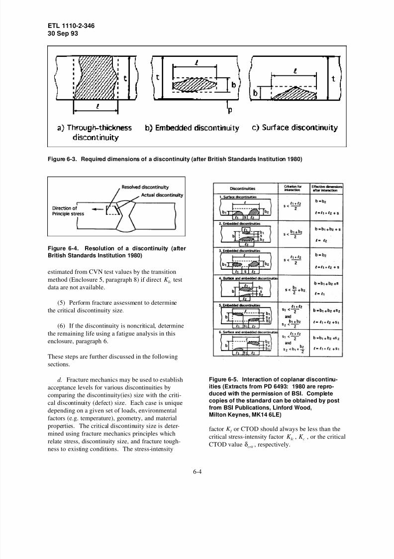
8/6/2019 US ARmy Corps of Engineers - Structural Inspection of Existi
http://slidepdf.com/reader/full/us-army-corps-of-engineers-structural-inspection-of-existi 28/53
ETL 1110-2-34630 Sep 93
estimated from CVN test values by the transition
Figure 6-3. Required dimensions of a discontinuity (after British Standards Institution 1980)
Figure 6-4. Resolution of a discontinuity (after
British Standards Institution 1980)
method (Enclosure 5, paragraph 8) if direct K Ic test
data are not available.
(5) Perform fracture assessment to determine
the critical discontinuity size.
(6) If the discontinuity is noncritical, determine
the remaining life using a fatigue analysis in this
enclosure, paragraph 6.
These steps are further discussed in the following
sections.
d. Fracture mechanics may be used to establish
acceptance levels for various discontinuities by
comparing the discontinuity(ies) size with the criti-
cal discontinuity (defect) size. Each case is unique
depending on a given set of loads, environmental
factors (e.g. temperature), geometry, and material
properties. The critical discontinuity size is deter-
mined using fracture mechanics principles which
relate stress, discontinuity size, and fracture tough-
ness to existing conditions. The stress-intensity
Figure 6-5. Interaction of coplanar discontinu-
ities (Extracts from PD 6493: 1980 are repro-
duced with the permission of BSI. Completecopies of the standard can be obtained by post
from BSI Publications, Linford Wood,
Milton Keynes, MK14 6LE)
factor K I or CTOD should always be less than the
critical stress-intensity factor K Ic , K c , or the critical
CTOD value δcrit , respectively.
6-4
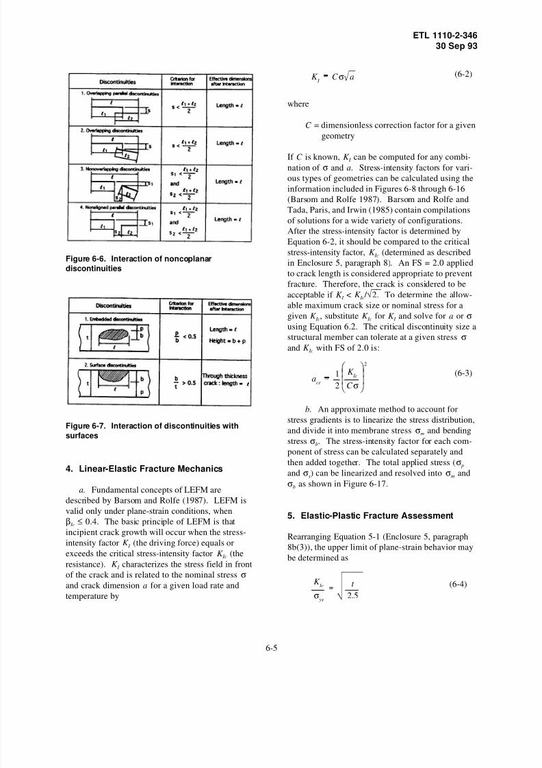
8/6/2019 US ARmy Corps of Engineers - Structural Inspection of Existi
http://slidepdf.com/reader/full/us-army-corps-of-engineers-structural-inspection-of-existi 29/53
ETL 1110-2-34630 Sep 93
Figure 6-6. Interaction of noncoplanar
discontinuities
Figure 6-7. Interaction of discontinuities with
surfaces
4. Linear-Elastic Fracture Mechanics
a. Fundamental concepts of LEFM are
described by Barsom and Rolfe (1987). LEFM is
valid only under plane-strain conditions, when
β Ic ≤ 0.4. The basic principle of LEFM is that
incipient crack growth will occur when the stress-
intensity factor K I (the driving force) equals or
exceeds the critical stress-intensity factor K Ic (the
resistance). K I characterizes the stress field in front
of the crack and is related to the nominal stress σand crack dimension a for a given load rate and
temperature by
(6-2)K I
C σ a
where
C = dimensionless correction factor for a given
geometry
If C is known, K I can be computed for any combi-
nation of σ and a. Stress-intensity factors for vari-
ous types of geometries can be calculated using the
information included in Figures 6-8 through 6-16
(Barsom and Rolfe 1987). Barsom and Rolfe and
Tada, Paris, and Irwin (1985) contain compilations
of solutions for a wide variety of configurations.
After the stress-intensity factor is determined by
Equation 6-2, it should be compared to the critical
stress-intensity factor, K Ic (determined as described
in Enclosure 5, paragraph 8). An FS = 2.0 applied
to crack length is considered appropriate to prevent
fracture. Therefore, the crack is considered to be
acceptable if K I < K Ic / √ 2. To determine the allow-
able maximum crack size or nominal stress for a
given K Ic, substitute K Ic for K I and solve for a or σusing Equation 6.2. The critical discontinuity size a
structural member can tolerate at a given stress σand K Ic with FS of 2.0 is:
(6-3)a
cr
1
2
K Ic
C σ
2
b. An approximate method to account for
stress gradients is to linearize the stress distribution,
and divide it into membrane stress σm and bending
stress σb. The stress-intensity factor for each com-
ponent of stress can be calculated separately and
then added together. The total applied stress (σ p
and σs) can be linearized and resolved into σm and
σb as shown in Figure 6-17.
5. Elastic-Plastic Fracture Assessment
Rearranging Equation 5-1 (Enclosure 5, paragraph8b(3)), the upper limit of plane-strain behavior may
be determined as
(6-4)K Ic
σ ys
t
2.5
6-5

8/6/2019 US ARmy Corps of Engineers - Structural Inspection of Existi
http://slidepdf.com/reader/full/us-army-corps-of-engineers-structural-inspection-of-existi 30/53
ETL 1110-2-34630 Sep 93
Figure 6-8. Through-thickness crack (copyright
ASTM. Reprinted with permission)
Figure 6-9. Double-edge crack (Barsom/Rolfe,
FRACTURE AND FATIGUE CONTROL IN STRUC-
TURES: Applications of Fracture Mechan-
ics,©1987, p 40. Reprinted by permission of
Prentice-Hall, Inc., Englewood Cliffs, NJ.)
6-6

8/6/2019 US ARmy Corps of Engineers - Structural Inspection of Existi
http://slidepdf.com/reader/full/us-army-corps-of-engineers-structural-inspection-of-existi 31/53
ETL 1110-2-34630 Sep 93
Figure 6-10. Single-edge crack (copyright ASTM.
Reprinted with permission)
Figure 6-11. Cracks growing from round holes
(copyright ASTM. Reprinted with permission)
6-7

8/6/2019 US ARmy Corps of Engineers - Structural Inspection of Existi
http://slidepdf.com/reader/full/us-army-corps-of-engineers-structural-inspection-of-existi 32/53
ETL 1110-2-34630 Sep 93
Figure 6-12. Cracks growing from elliptical holes
(Barsom/Rolfe, FRACTURE AND FATIGUE CON-
TROL IN STRUCTURES: Applications of Fracture
Mechanics,©1987, p 43. Reprinted by permission
of Prentice-Hall, Inc., Englewood Cliffs, NJ.)
When this upper limit is exceeded, extensive plasticdeformation occurs at the crack tip (crack tip blunt-
ing) and a nonlinear EPFM model must be used for
analysis. (LEFM analysis using K c may be used if
the applied stress is less than yield stress.) Crack
growth criteria for nonlinear fractures can be
modeled by an R-curve, J-integral, or CTOD analy-
sis (Barsom and Rolfe 1987). The CTOD method
is the recommended method of EPFM analysis for
evaluating steel lock gates. The recommended
procedure for cases where the applied stress
(σ p + σs) is greater than the yield stress (British
Standards Institution 1980) is as follows:
a. Determine the effective discontinuity
parameter a. This is the equivalent through thick-
ness dimension which would yield the same stress
intensity as the actual discontinuities under the same
load.
(1) For through-thickness discontinuities,
a = /2.
(2) For surface discontinuities, a is deter-
mined by Figure 6-18.
(3) For embedded discontinuities, a is deter-
mined by Figure 6-19.
b. Determine allowable discontinuity parame-ter am which is calculated by:
(6-5)am
C
δcrit
ε y
where
ε y = yield strain of the material
δcrit = critical CTOD (determined according to
Enclosure 5, paragraph 8)
C = values determined by Figure 6-20
In determination of C , if the sum of primary and
secondary stresses, excluding residual stress, is less
than 2σ ys, the total stress ratio (σ p + σs)/ σ ys (includ-
ing residual stress) is used as the abscissa in
Figure 6-20. If this sum exceeds 2σ ys, an elastic-
plastic stress analysis should be carried out to deter-
mine the maximum equivalent plastic strain which
would occur in the region containing the discontinu-
ity if the discontinuity were not present. The value
of C may then be determined using the strain ratio,
ε / ε y as the abscissa in Figure 6-20.
c. If the effective discontinuity parameter a is
smaller than the allowable discontinuity parameter
am, then the discontinuity is acceptable. Using the
procedure described in paragraph 5b, this enclosure,
results in an FS of approximately 2.0 in the deter-
mination of am; Figure 6-20 was developed as a
design curve. Therefore, the calculated critical
crack size would be equal to 2.0 am (British Stan-
dards Institution 1980).
6. Fatigue Analysis
a. Fatigue is the process of cumulative dam-
age caused by repeated cyclic loading. Fatigue
damage occurs at stress-concentrated regions where
the localized stress exceeds the yield stress of the
material. After a certain number of cyclic loads,
the accumulated damage causes the initiation and
propagation of a crack.
6-8

8/6/2019 US ARmy Corps of Engineers - Structural Inspection of Existi
http://slidepdf.com/reader/full/us-army-corps-of-engineers-structural-inspection-of-existi 33/53
ETL 1110-2-34630 Sep 93
Figure 6-13. Edge-notched beam in bending (Barsom/Rolfe, FRACTURE AND FATIGUE CONTROL IN
STRUCTURES: Applications of Fracture Mechanics,©1987, p 45. Reprinted by permission of Prentice-Hall,
Inc., Englewood Cliffs, NJ.)
b. The total fatigue life is the sum of the
fatigue crack-initiation life and the fatigue crack-
propagation life to a critical size (Barsom and Rolfe
1987).
N T = N i + N p (6-6)
where
N T = total fatigue life
N i = initiation life
N p = propagation life
c. All steels have microscopic discontinuities,
and welded structures always contain larger discon-
tinuities due to the welding process. Thus, the main
concern in fatigue assessment of welded structures
is to determine the crack-propagation life before
reaching the critical crack size which results in
brittle fracture. The life of a structural component
which contains a crack is governed by the rate of subcritical crack propagation.
d. Fatigue analysis methods described in para-
graphs 7 and 8 are based on extensive analyses of
test results from numerous specimens. Variation in
test data is large, and inherent uncertainty exists in
defining load and strength parameters. Therefore,
fatigue life predictions should be used as a means to
evaluate a reliable service life, not to actually pre-
dict when a structure will fail.
7. Fatigue Crack-Propagation (Barsom and
Rolfe 1987)
The fatigue crack-propagation behavior for metals is
shown in Figure 6-21. Figure 6-21 is a plot (log10
scale) of the rate of fatigue crack growth per cycle
of load (da/dN) versus the variation of the stress-
intensity factor (∆K I ). The parameter a denotes
crack length, N the number of cycles, and ∆K I the
stress-intensity factor range, K Imax to K Imin. Based on
Figure 6-21, fatigue-crack behavior for steel can be
characterized by three regions:
a. Region I: In region I, for levels of ∆K I
below a certain threshold, cracks do not propagateunder cyclic stress fluctuations. Conservative esti-
mates of fatigue threshold, ∆K th, can be determined
by
∆K th = 6.4(1 - 0.85R) ksi-√ in. for R > 0.1
∆K th = 5.5 ksi-√ in. for R < 0.1 (6-7)
6-9

8/6/2019 US ARmy Corps of Engineers - Structural Inspection of Existi
http://slidepdf.com/reader/full/us-army-corps-of-engineers-structural-inspection-of-existi 34/53
ETL 1110-2-34630 Sep 93
Figure 6-14. Embedded elliptical or circular crack (Barsom/Rolfe, FRACTURE AND FATIGUE CONTROL IN
STRUCTURES: Applications of Fracture Mechanics,©1987, p 47. Reprinted by permission of Prentice-Hall,
Inc., Englewood Cliffs, NJ.)
6-10

8/6/2019 US ARmy Corps of Engineers - Structural Inspection of Existi
http://slidepdf.com/reader/full/us-army-corps-of-engineers-structural-inspection-of-existi 35/53
ETL 1110-2-34630 Sep 93
Figure 6-15. Surface crack (Barsom/Rolfe, FRACTURE AND FATIGUE CONTROL IN STRUCTURES: Appli-
cations of Fracture Mechanics,©1987, p 48. Reprinted by permission of Prentice-Hall, Inc.,
Englewood Cliffs, NJ.)
where
R = stress ratio (i.e. fatigue ratio)
expressed as
R = σmin / σmax (6-8)
Residual stress should be considered for a crack
near weld area. If ∆K I is less than ∆K th, cracks do
not propagate.
b. Region II: The fatigue crack-propagation
behavior for ∆K I > ∆K th in region II (i.e. linear
portion of the plot on Figure 6-21) may be repre-
sented by
da/dN = 3.6x10⁻¹⁰ (∆K I )3 (6-9)
for ferrite-pearlite steels
and
da/dN = 0.66x10⁻⁸ (∆K I )2.25 (6-10)
for martensitic steels
(1) For Equations 6-9 and 6-10, a is in units
of inches, and ∆K I in units of kips per square
inch-√ in. ASTM A36-91 and A572-91 (1991b andd) Grade 50 steels are classified as ferrite-pearlite
steels, while ASTM A514-91/517 (ASTM 1991c
and 1990b, respectively) steels are martensitic
steels. The above equations were based on analyses
in air, at room temperature.
6-11

8/6/2019 US ARmy Corps of Engineers - Structural Inspection of Existi
http://slidepdf.com/reader/full/us-army-corps-of-engineers-structural-inspection-of-existi 36/53
ETL 1110-2-34630 Sep 93
Figure 6-16. Cracks with wedge forces (Barsom/Rolfe, FRACTURE AND FATIGUE CONTROL IN STRUC-
TURES: Applications of Fracture Mechanics,©1987, p 52. Reprinted by permission of Prentice-Hall, Inc.,
Englewood Cliffs, NJ.)
Figure 6-17. Linearization of stresses (Extracts from PD 6493: 1980 are reproduced with the permission of
BSI. Complete copies of the standard can be obtained by post from BSI Publications, Linford Wood, Milton
Keynes, MK14 6LE)
6-12

8/6/2019 US ARmy Corps of Engineers - Structural Inspection of Existi
http://slidepdf.com/reader/full/us-army-corps-of-engineers-structural-inspection-of-existi 37/53

8/6/2019 US ARmy Corps of Engineers - Structural Inspection of Existi
http://slidepdf.com/reader/full/us-army-corps-of-engineers-structural-inspection-of-existi 38/53
ETL 1110-2-34630 Sep 93
Figure 6-19. Relation between dimensions of a discontinuity and the parameter a for embedded disconti-
nuities (Extracts from PD 6493: 1980 are reproduced with the permission of BSI. Complete copies of the
standard can be obtained by post from BSI Publications, Linford Wood, Milton Keynes, MK14 6LE)
6-14

8/6/2019 US ARmy Corps of Engineers - Structural Inspection of Existi
http://slidepdf.com/reader/full/us-army-corps-of-engineers-structural-inspection-of-existi 39/53
ETL 1110-2-34630 Sep 93
Figure 6-20. Values of constant C for different
loading conditions (Extracts from PD 6493: 1980
are reproduced with the permission of BSI. Com-
plete copies of the standard can be obtained by
post from BSI Publications, Linford Wood, Milton
Keynes, MK14 6LE)
Figure 6-21. Fatigue-crack growth in steel
(2) Extensive fatigue-crack growth rate data
for weld metals and heat-affected-zones (HAZ)
show that the fatigue rate in weld metals and HAZ
are equal to or less than that in the base metals.
Thus, the above equations can be used for conserva-
tive estimates of fatigue-crack growth rates in base
metals, weld metals, and HAZ’s.
c. Region III: Region III is characterized by a
significant increase in the fatigue-crack growth rate
per cycle over that predicted for Region II. At a
certain value of ∆K I , the crack growth rate acceler-
ates dramatically. For materials of high fracture
toughness, the stress-intensity factor range value
corresponding to acceleration in the fatigue-crack
growth rate (i.e. transition from Region II to
Region III) for zero to tension loading can be
determined by
K T = 0.04 ( E σ ys)1/2
(6-11)
When the K Ic of the material is less than K T , accel-
eration in the fatigue rate occurs at a stress-intensity
factor value slightly below K Ic. Due to the acceler-
ation in crack growth rate, a significant increase in
fracture toughness of a steel above K T may have a
negligible effect on total fatigue life. Additionally,
extrapolation of Region II behavior to Region III
may overestimate the total fatigue life significantly.
8. Fatigue Assessment Procedures
The procedure to analyze Region II crack growth
behavior in steels and weld metals using fracture
mechanics concepts as recommended by Barsom
and Rolfe (1987) is as follows:
a. On the basis of the inspection data, deter-
mine the maximum initial discontinuity size ao
present in the member being analyzed and the
associated K I .
b. Knowing K Ic and the nominal maximum
design stress, calculate the critical discontinuity
size, acr (Equation 6-1), that would cause failure by
brittle fracture.
c. Determine fatigue crack growth rate for
type of steel (Equations 6-9 and 6-10) (i.e
ferrite-pearlite or martensitic steel).
6-15

8/6/2019 US ARmy Corps of Engineers - Structural Inspection of Existi
http://slidepdf.com/reader/full/us-army-corps-of-engineers-structural-inspection-of-existi 40/53
ETL 1110-2-34630 Sep 93
d. Determine ∆K I using the appropriate expres-
sion for K I , the estimated initial discontinuity size
ao, and the range of live load stress ∆σ (i.e. cyclic
stress range). For cases of variable amplitude load-
ing, a spectrum of various discrete stress ranges ∆σi
exists. In these cases, an effective stress range ∆σe
should be used in determining ∆K I . ∆σe can becalculated as the root-mean-cube of the discrete
stress ranges ∆σi,
(6-12)∆σe
m
i 1
ni
(∆σi)3
N
1/3
where
ni = number of cycles corresponding to ∆σi
N = total number of cycles considered
m = number of discrete stress ranges considered
A live load stress range ∆σ, which is due to cyclic
compression stresses, may be detrimental in regions
where tensile residual stress exists. In these
regions, cracks may propagate, since the addition of
tensile residual stresses will result in an applied
stress range of tension and compression.
e. Integrate the crack growth rate expression
(i.e. Equations 6-9 and 6-10) between the limits of
ao (at the initial K I ) and acr (at K Ic) to obtain the
life of the structure prior to failure. To identify
inspection intervals, integration may be applied withthe upper limit being tolerable discontinuity size at .
An arbitrary safety factor based on analysis uncer-
tainties may be applied to acr to obtain at (for
example, FS = 2.0 was used in Equation 6-3).
Another consideration to specifying a tolerable
discontinuity size is crack growth rate. The at
should be chosen so that da/dN is relatively small
and a reasonable length of time remains before the
critical size is reached.
f. For a determination of ao.
(1) See Figure 6-3a for through-thickness
discontinuities.
(2) For embedded discontinuities (Figure 6-3b),
assume that the discontinuity grows until it reaches
a circular shape (b= /2). Subsequently, it grows
radially and eventually protrudes a surface at which
time it should be treated as a surface discontinuity
of length .
(3) See Figure 6-3c for surface discontinuities.
Initial propagation will result in a semicircular
shape. Further propagation will result in the dis-continuity reaching the other surface at which time
it should be treated as a through thickness
discontinuity.
9. Development of Inspection Schedules
Inspection schedules can be developed from crack
length versus fatigue life curves. Figure 6-22
shows a typical crack length-fatigue life (a - N)
curve, which can be obtained from Equation 6-9
or 6-10. Critical crack length is determined based
on K Ic and maximum design stress as discussed inparagraph 8, this enclosure. The time when repair
is needed can be determined considering FS, i.e.,
ar = acr /(FS). Remaining loading cycles before
repair are then determined from ai and ar using an
a-N curve as shown in Figure 6-22. Inspection
intervals for a gate can be determined from the
remaining fatigue life of the members (Common-
wealth of Pennsylvania, Department of Transporta-
tion 1988).
Figure 6-22. Development of maintenance
schedule
6-16
8/6/2019 US ARmy Corps of Engineers - Structural Inspection of Existi
http://slidepdf.com/reader/full/us-army-corps-of-engineers-structural-inspection-of-existi 41/53
ETL 1110-2-34630 Sep 93
10. Example Fracture Analysis
Cracks of various shapes were revealed on two
tension members on a lock gate by NDT inspection.
One member has the cross-sectional dimensions of
4 in. thick by 12 in. wide. The other member is
1 in. thick by 12 in. wide. The crack types andshapes include: a) single-edge crack; b) through-
thickness center crack; c) surface crack along the
12-in. side (a/2c = 0.1 and 0.2), and d) embedded
circular cracks.
The material properties at the minimum service
temperature of 30 oF were determined by material
testings and are summarized as follows:
σ ys = 50 ksi σult = 80 ksi
E = 30,000 ksi K Ic = 60 ksi-√ in.
K Id = 40 ksi-√ in. δcrit = 0.002 in. (static)
δcrit = 0.001 in. (dynamic)
From structural analysis, the maximum applied
tensile stress is 30 ksi. For each cracked member,
the critical crack size will be determined for each
cracking condition under static loading and dynamic
loading, respectively:
a. Example for 4- by 12-in. plate:
β Ic
1
t
K Ic
σ ys
2
1
4
60
50
2
0.36 (Equation 5 1)
β Ic
<0.4; therefore, LEFM is applicable.
(1) Single-edge crack (see Figure 6-10).
K I
1.12σ πa k
a
b
C 1.12 π k
a
bin Equation 6 2
assume k
a
b1.0
acr
1
π
K Ic
1.12σ
2
1.02 in.
(Equation 6 1 with no FS)
a/b = 0.17 and = 1.06; therefore,k
a
b
iteration is needed for acr and . Afterk
a
b
iteration, acr = 0.92 in. ( = 1.05)k
a
b
With FS = 2.0, acr = 0.5 (0.92) = 0.46 in.
for dynamic loading:
acr
0.5
π
K Id
1.12σ
2
0.23 in.
(2) Through-thickness center crack
(Figure 6-8).
K I
σ πa2b
πatan
πa
2b
assume 2b
πatan
πa
2b1.0
acr
1
π
K Ic
σ
2
1.27 in.;
2bπ a
tan πa2b
1.02
After iteration, acr = 1.22 in.
With FS = 2.0, acr = 1.22/2 = 0.61 in.
for dynamic loading:
acr
0.5
π
K Id
σ
2
0.28 in.
(3) Surface crack along the 12-in. side (see
Figure 6-15).
K I
1.12σ π a
Q M
K
(a) a/2c = 0.1
6-17

8/6/2019 US ARmy Corps of Engineers - Structural Inspection of Existi
http://slidepdf.com/reader/full/us-army-corps-of-engineers-structural-inspection-of-existi 42/53

8/6/2019 US ARmy Corps of Engineers - Structural Inspection of Existi
http://slidepdf.com/reader/full/us-army-corps-of-engineers-structural-inspection-of-existi 43/53
ETL 1110-2-34630 Sep 93
The maximum stress level is 30 ksi and the mini-
mum stress is 0 ksi. A curve relating the initial
surface flaw size ai to number of cycles to failure
N p will be developed. From Figure 6-15
K I
1.12
σ π
a
Q M
K
σσ
ys
30
500.6 and Q 1.39 ( Figure 6 14)
assume M k = 1.0.
With FS 2.0, acr
0.5Q
π
K IC
1.12σ
2
0.71 in.
(for crack sizes up to a = 0.71 in., M k = 1.0)
for ferrite-pearlite steel, da/dN = 3.6×10⁻¹⁰ (∆K I )3
(Equation 6-9)
∆K I
1.12 ∆σ π a
Q50.5 a
Fatigue life can be determined as:
N ⌡⌠ acr
ai
da
(3.6×10 10)(∆K I )3
N 1
(3.6×10¹⁰
)(50.5)3
⌡
⌠ acr
ai
a 3/2 da
N (4.31×10⁴)
1
ai
1
acr
The curve for fatigue life N as a function of initial
crack length ai for this example is shown in
Figure 6-23.
12. Example of Fracture and Fatigue
Evaluation
a. Single-edge crack. Figure 6-24 shows a
horizontal girder with a single-edge crack. The
initial crack length is assumed to be 1/8 in.. The
flange plate containing the edge crack is assumed to
be under a cyclic load from zero to maximum ten-
sion (i.e., fatigue ratio R = 0). The stress ranges
Figure 6-23. Fatigue life (N )-initial crack-length
(a i ) curve
vary from 18 ksi to 27 ksi. The fatigue life can be
calculated using the following crack growth equa-
tion (Equation 6-9):
da
dN 3.6 × 10 10(∆K
I )3
where
K I
1.12σ πa k
a
b
By integrating the crack growth equation, the life of
the propagating crack can be determined for any
crack length.
N ⌡⌠ acr
ai
da
(3.6×10 10)(∆K I )3
where
K I = stress-intensity factor which is a function
of crack length
ai = initial crack length
acr =1
π
K Ic
1.12σk (a / b)
2
(Equation 6 1)
With K Ic assumed to be 35 ksi-√ in. and a maximum
stress of 18 ksi, acr = 0.89 in. using the procedure
described in paragraph 10a(1).
6-19
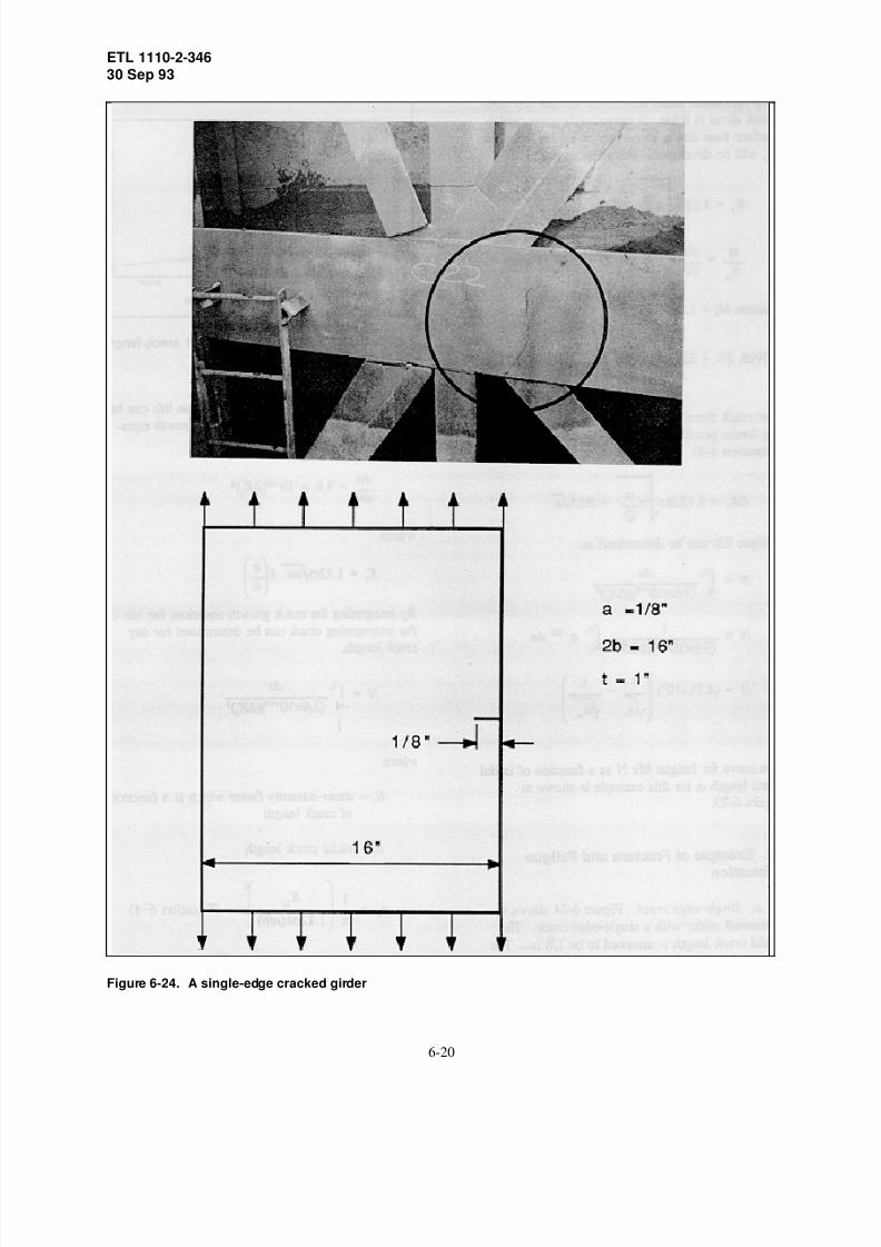
8/6/2019 US ARmy Corps of Engineers - Structural Inspection of Existi
http://slidepdf.com/reader/full/us-army-corps-of-engineers-structural-inspection-of-existi 44/53
ETL 1110-2-34630 Sep 93
Figure 6-24. A single-edge cracked girder
6-20

8/6/2019 US ARmy Corps of Engineers - Structural Inspection of Existi
http://slidepdf.com/reader/full/us-army-corps-of-engineers-structural-inspection-of-existi 45/53
ETL 1110-2-34630 Sep 93
Figure 6-25a shows the calculated crack growth
versus life cycle for a stress range of 18 ksi
(1/2 σ ys). The remaining life N , calculated by the
above equation, is 207,700 cycles. If the structure
operates 10,000 times per year, then the remaining
life of the girder is:
Critical crack length (determined by Equation 6-1)
207,700
10,00020.8 years
is a function of external loading as shown in
Figure 6-25b. Figure 6-25c shows the fatigue life
for stress ranges varying from 18 ksi to 27 ksi
calculated using the crack growth equation with
variable stress and acr . The remaining life of the
girder flange containing a 1/8-in. initial crack is
shown in the figure as a function of stress.
b. Double-edge crack. A girder flange contain-
ing double-edge cracks is shown in Figure 6-26.
The crack growth curves were calculated for stress
ranges varying from 10 to 20 ksi. The same inte-
gration procedure as used for the single-edge crack
case is employed for calculating the fatigue life. A
1/8-in. initial crack length is also assumed in this
case. The predicted crack growth curve for stress
range of 18 ksi is shown in Figure 6-27a. The
remaining life of the girder flange plate for various
stress ranges is also shown in Figure 6-27c.
c. Surface crack. Figure 6-28 shows a crack
for which it is assumed initiated in the diagonalbracing member from a surface crack at the corner
of the bracket. It is assumed that the crack propa-
gated through the thickness of the bracing member
and then grew toward the edge of the flange plate.
A single-edge crack condition similar to the first
example case was developed. The fracture and
fatigue analysis of this example consists of three
propagation steps.
(1) The first step is to analyze the crack prop-
agation of a hemispheric surface crack having an
initial radius of 1/16 in. When the surface crack
breaks through the surface on the other side of theplate (i.e., the radius of hemispheric crack becomes
the same as the plate thickness, 3/8 in.), a through-
thickness crack condition is reached.
(2) The second step is to analyze crack growth
of a plate containing a through-thickness crack.
Once the through-thickness crack reaches the edge
Figure 6-25. Curves for fatigue life of a girder
with a single-edge crack
of the plate, the single-edge crack condition is
developed.
(3) The third step is to analyze crack growth
of the edge crack. The total remaining life of the
6-21
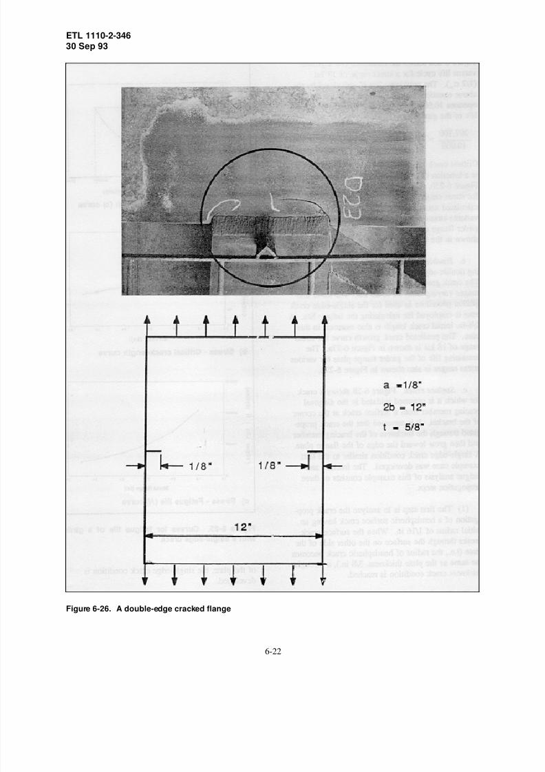
8/6/2019 US ARmy Corps of Engineers - Structural Inspection of Existi
http://slidepdf.com/reader/full/us-army-corps-of-engineers-structural-inspection-of-existi 46/53
ETL 1110-2-34630 Sep 93
Figure 6-26. A double-edge cracked flange
6-22

8/6/2019 US ARmy Corps of Engineers - Structural Inspection of Existi
http://slidepdf.com/reader/full/us-army-corps-of-engineers-structural-inspection-of-existi 47/53
ETL 1110-2-34630 Sep 93
Figure 6-27. Curves for fatigue life of a flange
with a double-edge crack
diagonal bracing member from the initial hemi-
spheric surface crack can be determined by adding
the three propagation lives. The calculated crack
growth curve for a stress range of 18 ksi is shown
in Figure 6-29a. The total remaining life and criti-
cal crack length are also shown in Figures 6-29b,
and c, for stress ranges varying from 10 to 20 ksi.
13. Recommended Solutions
a. The recommended solutions to the cracking
problems can be addressed in short- and longterm
solutions. The short-term solution is to repair the
fractured members using qualified welding proce-
dures and improved fatigue details or bolted coverplates. This temporary measure will ensure contin-
uous operation of the structure without catastrophic
failure.
b. A long-term solution will involve detailed
inspection and evaluation of the critical members
and connections. Structural analysis using a finite
element model may be necessary to identify the
critical structural members and connections. Vari-
ous loading conditions determined during the course
of previous activities need to be considered in the
analysis. The fatigue category of various welded
connections should be assessed according to theAmerican Association of State Highway and Trans-
portation Officials (AASHTO) Standard Specifica-
tion for Highway Bridges (AASHTO 1989) or the
ANSI/AWS D1.1-92 Structural Welding Code
(ANSI/AWS 1992). The expected life of the criti-
cal connections can be estimated in accordance with
the respective fatigue category.
c. To maintain satisfactory performance of a
structure, a maintenance plan needs to be devel-
oped. This maintenance plan should include peri-
odic inspections and evaluations. For the worst
loading situation, the maximum stress range can bepredicted from an appropriate structural analysis.
The inspection intervals can be determined from a
crack growth curve of maximum stress range. The
inspection intervals shall be a fraction of the
remaining life cycles of the critical members and
connections. These fraction life cycles shall corre-
spond to a crack size less than one-half of the criti-
cal crack length (i.e. FS = 2.0).
d. Recommended inspection intervals may be
computed using fatigue principles as described in
paragraph 9, this enclosure. Using the example
found in paragraph 12a of this enclosure, the
inspection schedule can be determined from the
fatigue life curve of the single-edge crack in the
primary member. The maximum stress range is
assumed as 18 ksi. The procedure is shown in the
following steps.
6-23

8/6/2019 US ARmy Corps of Engineers - Structural Inspection of Existi
http://slidepdf.com/reader/full/us-army-corps-of-engineers-structural-inspection-of-existi 48/53
ETL 1110-2-34630 Sep 93
Figure 6-28. A stiffening member with a crack
6-24

8/6/2019 US ARmy Corps of Engineers - Structural Inspection of Existi
http://slidepdf.com/reader/full/us-army-corps-of-engineers-structural-inspection-of-existi 49/53
ETL 1110-2-34630 Sep 93
Figure 6-29. Curves for a fatigue life of a stiffening member with a
surface crack
6-25

8/6/2019 US ARmy Corps of Engineers - Structural Inspection of Existi
http://slidepdf.com/reader/full/us-army-corps-of-engineers-structural-inspection-of-existi 50/53
ETL 1110-2-34630 Sep 93
(1) Determine critical crack length:
acr = 0.89 in. (this enclosure, paragraph 12a)
(2) Determine crack length when repair is
needed (Figure 6-22):
ar = 0.89/2 = 0.45 in. (FS = 2.0)
(3) Determine fatigue life from fatigue life N
versus crack length a curve:
N = 160,000 cycles
160,000/10,000 = 16 years (10,000 cycles/year)
Therefore, the girder should be inspected within
16 years after the initial crack (ai = 1/8 in.) was
found.
6-26

8/6/2019 US ARmy Corps of Engineers - Structural Inspection of Existi
http://slidepdf.com/reader/full/us-army-corps-of-engineers-structural-inspection-of-existi 51/53
ETL 1110-2-34630 Sep 93
REFERENCES FOR ENCLOSURES
a. American Association of State Highway and
Transportation Officials. (1989). "Standard specifi-
cation for highway bridges," 14th ed., Washington,
DC.
b. American National Standards Institute.
(1985). "Surface texture," Designation: ANSI
B46.1-85, New York.
c. American National Standards Institute/
American Welding Society. (1986). "Guide for the
nondestructive inspection of welds," Designation:
ANSI/AWS B1.10-86, Miami, FL
d. American National Standards Institute/
American Welding Society. (1988). "Standard and
guide for qualification and certification of welding
inspectors," Designation: ANSI/AWS QC1-88,
Miami, FL.
e. American National Standards Institute/
American Welding Society. (1992). "Structural
welding code-steel," Designation: ANSI/AWS
D1.1-92, Miami, FL.
f. American Society of Mechanical Engineers.
(1978). "Rules for inservice inspection of nuclear
power plant components," ASME Boiler and Pres-
sure Vessel Code, Section XI, 1977 ed., New York.
g. American Society for Nondestructive
Testing. (1980). "Recommended practice No.
SNT-TC-1A," Columbus, OH.
h. American Welding Society. (1985). "Stan-
dard methods for mechanical testing of welds,"
Designation: B4.0-85, Miami, FL.
i. American Welding Society. (1986).
"Standard symbols for welding, brazing and non-
destructive examination," Designation: A2.4-86,
Miami, FL.
j. American Welding Society. (1989).
"Standard welding terms and definitions," Designa-
tion: A3.0-89, Miami, FL.
k. American Society for Testing and Materials.
(1984). "Standard test method for Brinell hardness
of metallic materials," Designation: E10-84,
Philadelphia, PA.
l. American Society for Testing and Materials.(1987a). "Standard test method for Vickers hard-
ness of metallic materials," Designation: E92-82
(Reapproved 1987), Philadelphia, PA.
m. American Society for Testing and
Materials. (1987b). "Standard test method for
indentation hardness of metallic materials by
portable hardness testers," Designation: E110-82
(Reapproved 1987), Philadelphia, PA.
n. American Society for Testing and
Materials. (1988). "Standard hardness conversion
tables for metals," Designation: E140-88,
Philadelphia, PA.
o. American Society for Testing and
Materials. (1989a). "Standard practice for load
verification of testing machines," Designation:
E4-89, Philadelphia, PA.
p. American Society for Testing and
Materials. (1989b). "Standard test methods for
chemical analysis of steel, cast iron, open-hearth
iron, and wrought iron," Designation: E30-89,
Philadelphia, PA.
q. American Society for Testing and
Materials. (1989c). "Standard practice for hole-
type image quality indicators used for radiography,"
Designation: E1025-84 (Reapproved 1989),
Philadelphia, PA.
r. American Society for Testing and Materials.
(1989d). "Standard test method for crack-tip
opening displacement (CTOD) fracture toughness
measurement," Designation: E1290-89,
Philadelphia, PA.
s. American Society for Testing and Materials.
(1990a). "Standard specification for straight-beam
ultrasonic examination of steel plates," Designation:
A435/A435M-90, Philadelphia, PA.
t. American Society for Testing and Materials.
(1990b). "Standard specification for pressure vessel
R-1

8/6/2019 US ARmy Corps of Engineers - Structural Inspection of Existi
http://slidepdf.com/reader/full/us-army-corps-of-engineers-structural-inspection-of-existi 52/53
ETL 1110-2-34630 Sep 93
plates, alloy steel, high-strength, quenched, and
tempered," Designation: A517/A517M-90,
Philadelphia, PA.
u. American Society for Testing and Materials.
(1990c). "Standard specification for ultrasonic
angle-beam examination of steel plates," Designa-tion: A577/A577M-90, Philadelphia, PA.
v. American Society for Testing and Materials.
(1990d). "Standard practice for ultrasonic pulse-
echo straight-beam examination by the contact
method," Designation: E114-90, Philadelphia, PA.
w. American Society for Testing and Materials.
(1990e). "Standard practice for ultrasonic contact
examination of weldments," Designation: E164-90,
Philadelphia, PA.
x. American Society for Testing and Materials.(1990f). "Standard test methods for chemical
analysis of carbon steel, low-alloy steel, silicon
electrical steel, ingot iron, and wrought iron,"
Designation: E350-90, Philadelphia, PA.
y. American Society for Testing and Materials.
(1990g). "Standard test method for plane-strain
fracture toughness of metallic materials," Designa-
tion: E399-90, Philadelphia, PA.
z. American Society for Testing and Materials.
(1990h). "Standard test method for controlling
quality of radiographic examination using wirepenetrameters," Designation: E747-90,
Philadelphia, PA.
aa. American Society for Testing and Materials.
(1990i). "Standard guide for controlling the quality
of industrial radiographic film processing," Designa-
tion: E999-90, Philadelphia, PA.
bb. American Society for Testing and Materials.
(1991a). "Specification for general requirements for
rolled steel plates, shapes, sheet piling, and bars for
structural use," Designation: A6/A6M-916,
Philadelphia, PA.
cc. American Society for Testing and Materials.
(1991b). "Standard specification for structural
steel," Designation: A36/A36M-91, Philadelphia,
PA.
dd. American Society for Testing and Mater-
ials. (1991c). "Standard specification for high-
yield-strength, quenched and tempered alloy steel
plate, suitable for welding," Designation:
A514/A514M-91, Philadelphia, PA.
ee. American Society for Testing and Mater-ials. (1991d). "Standard specification for high-
strength low-alloy Columbian-Vanadium steels of
structural quality," Designation: A572/A572M-91,
Philadelphia, PA.
ff. American Society for Testing and Mater-
ials. (1991e). "Specification for straight beam
ultrasonic examination of rolled steel structural
shapes," Designation: A898/A898M-91,
Philadelphia, PA.
gg. American Society for Testing and Mater-
ials. (1991f). "Standard test methods for tensiontesting of metallic materials," Designation: E8-91,
Philadelphia, PA.
hh. American Society for Testing and Mater-
ials. (1991g). "Standard guide for radiographic
testing," Designation: E94-91, Philadelphia, PA.
ii. American Society for Testing and Mater-
ials. (1991h). "Standard test method for liquid
penetrant examination," Designation: E165-91,
Philadelphia, PA.
jj. American Society for Testing and Mater-ials. (1991i). "Standard method for conducting
drop weight test to determine nil-ductility transition
temperature of ferritic steels," Designation: E208-
91, Philadelphia, PA.
kk. American Society for Testing and Mater-
ials. (1991j). "Standard practice for immersed
ultrasonic examination by the reflection method
using pulsed longitudinal waves," Designation:
E214-68 (Reapproved 1991), Philadelphia, PA.
ll. American Society for Testing and Mater-
ials. (1991k). "Standard reference radiographs for
appearance of radiographic images as certain
parameters are changed," Designation: E242-91,
Philadelphia, PA.
R-2

8/6/2019 US ARmy Corps of Engineers - Structural Inspection of Existi
http://slidepdf.com/reader/full/us-army-corps-of-engineers-structural-inspection-of-existi 53/53
ETL 1110-2-34630 Sep 93
mm. American Society for Testing and Materials.
(1991l). "Standard guide for magnetic particle
examination," Designation: E709-91, Philadelphia,
PA.
nn. American Society for Testing and Materials.
(1992a). "Standard test methods for Rockwell hard-ness and Rockwell superficial hardness of metallic
materials," Designation: E18-92, Philadelphia, PA.
oo. American Society for Testing and Materials.
(1992b). "Standard test methods for notched bar
impact testing of metallic materials," Designation:
E23-92, Philadelphia, PA.
pp. American Society for Testing and Materials.
(1992c). "Standard method for controlling quality
of radiographic testing," Designation: E142-92,
Philadelphia, PA.
qq. American Society for Testing and Materials.
(1992d). "Standard test method for guided bend
test for ductility of welds," Designation: E190-92,
Philadelphia, PA.
rr. American Society for Testing and Materials.
(1992e). "Standard method for radiographic exami-
nation of weldments," Designation: E1032-92,
Philadelphia, PA.
ss. American Society for Testing and Materials.
(1992f). "Standard terminology for nondestructive
examination," Designation: E1316-92, Philadelphia,PA.
tt. Barsom, J. M., and Rolfe, S. T. (1987).
"Fracture and fatigue control in structures," 2nd ed.,
Prentice-Hall, Englewood Cliffs, NJ.
uu. British Standards Institution. (1980).
"Guidance on some methods for the derivation of
acceptance levels for defects in fusion welded
joints," BS PD6493, London.
vv. Burdekin, F. M., Harrison, J. D.,
Kanazawa, T., Mashida, S., Ekwall, B.,Konkoly, T., and Muncher, L. (1975). "Proposed
assessment methods for flaws with respect to failure
by brittle fracture," Welding in the World ,
Document IIW-471-74, Vol 13, No. ½.
ww. Canadian Standards Association. (1917).
"Certification of Welding Inspectors," Designation:
CSA W178.2, Rexdale ON, Canada.
xx. Commonwealth of Pennsylvania, Depart-
ment of Transportation. (1988). "Guidelines for
fatigue and fracture safety inspection of bridges,"
Bridge Management Systems Division.
yy. Headquarters, Department of the Army.
(1993). "Design of hydraulic steel structures,"
Engineer Manual 1110-2-2105, Washington, DC.
zz. Headquarters, Department of the Army.
(1984). "Lock gates and operating equipment,"
Engineer Manual 1110-2-2703, Washington, DC.
aaa. Headquarters, Department of the Army.
(1988). "Periodic inspection and continuing evalua-
tion of completed civil works structures," Engineer
Regulation 1110-2-100, Washington, DC.
bbb. Tada, H., Paris, P. C., and Irwin, G. R.
(1985). "The stress analysis of cracks handbook,"
Paris Productions, Inc., Saint Louis, MO.