US ARMY ARMAMENT RESEARCH AND … · of sulfuric acid as the dehydrating agent for the water of...
208
z/ AD AD-E400 319 CONTRACTOR REPORT ARLCD-CR-79006 CONTINUOUS MANUFACTURING OF fNITROCELLULOSE BY MAGNESIUM NITRATE METHOD- VOLUME I TRUMAN K. DANIEL ET AL D - C RADFORD ARMY AMMUNITION PLANT -l-fT,;7-"A:2 RADFORD, VIRGINIA rn, J. AUG > L R. L. TRASK V A i E. 0. HANN C. W. LEWIS ARRADCOM, DOVER. NEW JERSEY C0-1 JUNE 1979 US ARMY ARMAMENT RESEARCH AND DEVELOPMENT COMMAND LARGE CALIBER WEAPON SYSTEMS LABORATORY DOVER, NEW JERSEY APPROVED FOR PUBLIC RELEASE: DISTRIBUTION UNLIMITED.
Transcript of US ARMY ARMAMENT RESEARCH AND … · of sulfuric acid as the dehydrating agent for the water of...

z/
AD
AD-E400 319
CONTRACTOR REPORT ARLCD-CR-79006
CONTINUOUS MANUFACTURING OF
fNITROCELLULOSE BY
MAGNESIUM NITRATE METHOD- VOLUME I
TRUMAN K. DANIEL ET AL D - CRADFORD ARMY AMMUNITION PLANT -l-fT,;7-"A:2
RADFORD, VIRGINIA rn,J. AUG > L
R. L. TRASK V A i
E. 0. HANNC. W. LEWIS
ARRADCOM, DOVER. NEW JERSEY
C0-1 JUNE 1979
US ARMY ARMAMENT RESEARCH AND DEVELOPMENT COMMANDLARGE CALIBER
WEAPON SYSTEMS LABORATORYDOVER, NEW JERSEY
APPROVED FOR PUBLIC RELEASE: DISTRIBUTION UNLIMITED.

The views, opinions, and/or findings containedin this report are those of the author(s) andshould not be construed as an official Depart-ment of the Army, position, policy or decision,unless so designated by other documentation.
Destroy this report when no longer needed. Donot return it to the originator.
The citation in this report of the names of com-mercial firms or commercially available pro-ducts or services does not constitute officialendorsement or approval of such commercialfirms, products, or services by the United StatesGovernment.

UNCLASS IH EDSECURITY CLASSIFICATION OF THIS PAGE (M~he Data Knter~d)
PAGE READ INSTRUCTIONSREPORT DOCUMENTATION PAE EFORE COMPLETIN4G FORM
1REPORT NUMBER 2GOTACCESSION NO. 3. RECIPIENT'S CATALOG NUMBER
4. TITLE (nd S.1btift.) S. TYPE OF REPORT a PERIOD COVERED
CONTINUOUS mANtwAcTuRe OF NITROCELLULOSE BY Final ReportMAGNESIUM NITRATE ML7T1'0D - VOLUM.I January 1972 - November 1977
6. PERFORMING 0 2.REPORT HUM~
PE.274 293 AD200.10)t-7. AUTHOR(.) 6. CONTRACT OR GRANT NUMBER(#)
Truman K. Daniel. et al, RAAPR. L. Trask, E. 0. Hann, and C. W. Lewis, ARRADCOM DAAAO9-77-C-4007
9. PERFORMING ORGANIZATION NAME AND ADDRESS 10. PROGRAM ELEMENT. PROJECT, TASK
Radford Army Ammunition Plat .s AREA I WORK UNIT NUMBERS
Hercules, Incorporated ~. DRORadford, Virginia 24141 MM&T Project 57X4013.-
If. CONTROLLING OFFICE NAME AND ADDRESS 12. REPORT DATE
ARRADCOM, TSD ue17Scientific &~ Technical Information Div (DRDAR-TSS) 13. NUMBER OF PAGESDover, New Jersey 078012014. MONITORING AGENCY NAME 8 AODRESSQif different Immo Con~trolling 016,.6) IS. SECURITY CLASS. (of this report)
ARRADCOM, LCWSL UcasfeManufacturing Technology Div (DRDAR-LCM-E)Dover, New Jersey 07801 IS.. DECLASSIFICATION/DOWNGRADING
16. DISTRIBUTION STATEMENT (of thie Report)
Approved for public release; distribution unlimited.
17. DISTRIB3UTION STATEMENT (of the abstract entered In Block 20. It different frotn Repos4 Ar
IS. SUPPLEMENTARY NOTES
This project was accomplished as part of the US Army's Manufacturing Methodsand Technology Program. The primary objective of this program is to develop,on a timely basis, manufacturing processes, techniques, and equipment for use
in the production of Army materiel.IS. KEY WORDS (Continue orn reerae ade linecoeeary and Identify by block nurmber) IMagnesium nitrate Ion-exchange systemNitrocellulose Viscosity boilAttrition mills Eimco extractorMMT-pollution abatement Durco filter
2. AST'RAcr ecCth.,d revore oetr m n..wt ad idauttfy by block nebe)
-The objectives of this project wiere to design, procure, install and evaluatepilot and prototype equipment for the continuous production of nitrocellulose(NC) by the magnesium nitrate process. Laboratory and bench-scale studieswere performed to establish methods, techniques, and basic design concepts forthe continuous prototype process. Laboratory-scale studies evaluated the con-ditions for nitration and purification of NC. Bench-scale studies establishednitration conditions, determined the use of attrition mills, and evaluated ionexchange as a means of recovering magnesium nitrate. -s' 0w
DD IA 7 1473 <*DITION OF I NOVS IS, 1E0S6LETE UNCLASSIFIEDSECURITY CLASSIFICATION OF THIS PAGE (Whten Date Entered)

UNCLASSIFIEDSECURITY CLASSIFICATION OF THIS PAGE(W= VW& Efer*0
20. ABST T (Continued)
Corrosion studies were used in evaluating construction materials and select-ing equipment for the continuous pilot plant. A nitration, purification,chemical recovery, and pollution abatement process flow was established. Equip-ment for the prototype plant was designed, procured, and installed.
Before the evaluation of the continuous pilot plant was begun, equipment
was modified to permit evaluation of an acid recycle system proposed for use
in the continuous mixed-acid NC manufacturing facility. Following this evalua-
tion, the project was terminated.
Volume I of this report contains unrestricted technical data. Volume IIcontains information of a proprietary nature.
Or,.
%
UNCLASSIFIEDSECURITY CLASSIFICATION OF THIS PAGE(WPhe Da* Pnteted)

SUMMARY
In the mid-1950's work was conducted by several agencies and plantson a process for nitrating cellulose utilizing magnesium nitrate in lieuof sulfuric acid as the dehydrating agent for the water of reaction.Several small lots of magnesium nitrate NC were prepared batchwise forevaluation. This NC was granular and harsh to the touch; however, thematerial did meet all of the requirements of the existing NC specification(JAN-N-244) with the exception of the 134.5C Heat Test (German acceleratedstability test).
The material was further processed into various propellants forevaluation of processing techniques and propellant characteristics. Reportspublished by Picatinny Arsenal stated that the NC failed to dehydrateproperly in the Loomis presses and required an increase in solvent-to-ingredient ratio to manufacture the propellants. The reports stated thatthe magnesium nitrate NC yielded propellants which were ballistically equalto propellants manufactured with the conventional mixed acid NC.
Based on the fact that magnesium nitrate NC had been successfullytested in military propellants and that the use of sulfuric acid is elimi-nated in the manufacture of NC by this process, thus reducing the amountof stream pollution, Picatinny Arsenal recommended that a pilot plant studybe funded to evaluate the process more extensively, but this recommendationwas not approved. However, in the late 1960's emphasis on reducing streampollutants resulted in a review of methods b} which these reductions couldbe accomplished. The magnesium nitrate NC process was revived, withmodifications, as a potential for effecting these reductions as associatedwith the manufacture of NC.
Bench-scale work showed that a continuous process for production ofNC using magnesium nitrate instead of sulfuric acid as a dehydrating agentwas technically feasible. The bench-scale studies investigated the nitra-tion of cotton linters and wood pulp and the use of an attrition millto initiate nitration, purification requirements for magnesium nitrate KNC, various ion exchange resins and systems for the recovery of magnesiumand nitrate ions from wastewater effluents, and corrosive effects onvarious candidate materials of construction to be used in the pilot plant.Blends of NC manufactured with the bench-scale equipment were providedUS Army Armament Research and Development Command (ARRADGOM) forsurveillance tests. Results of these tests indicated the NC wasacceptable for military use and are included in Appendix F. A pilot plantwas designed and built to evaluate this process. The pilot plant wasdesigned as a scaled-down version of the continuous mixed acid nitrationfacility in order to permit the adaptation of the process developed in thepilot plant to the production-scale equipment. Additional features to beevaluated in the pilot plant included the initiation of nitration inattrition mills, countercurrent washing of the NC on a dewatering filter
1 Ii
1i

and use of the filtrate as the initial countercurrent wash in the centri-fuge, and the use oi ion exchange resins to recover pollutants fromprocess wastewater streams. A subpilot-scale magnesium nitrate/nitricacid concentrator was built to determine operating conditions forconcentrating the spent nitrating mix for the pilot plant.
After a series of reviews with cognizant Government agencies, itwas decided to modify the continuous mixed acid process to permit therecovery of excess acid from the NC with a dewatering filter and torecycle the filtrate to the initial wash stage of the continuous centri-fuge as had been planned for the magnesium nitrate process. A decisionwas made to convert the magnesium nitrate pilot plant for evaluation ofthe modified mixed acid process. Work on the magnesium nitrate processwas terminated by the Project Manager. After evaluation of the modifiedmixed acid process under another project, the pilot plant was placed ina protective storage status.
2

TABLE OF CONTENTS
Page No.
Introduct ion 9
Background and Justification 9
Laboratory Investigation S e
Bench-Scale Evaluation 34
Bench-Scale Nitration Studies 34Viscosity Adjustment 47
Equipment 47
Viscosity Boiling Cuirves 53Viscosity Adjustment Summary 58
Ion Exchange Studies 58
Principle of Operation 58Selection of Resins 59Ion Exchange Unit 59Ion Exchange System Storage Tanks 60Ion Exchange System Process Flow 60Investigation 65Process (Filtered) Water Versus Drinking Water 67Summary of Ion Exchange Studies 67
Corrosion and Materials Selection 70Selection of Corrosion Tests 70Corrosion Specimens 77Test Results 79Design Recommendations for Pilot Plant 81Construction Materials
Process Flow 82
Pilot Plant Design and Construction 85
General Comments 85Equipment Layouts 86Electrical Components 86Building Modifications 89
1* 3
I SM - ,r.- * ..... ... .; . ,. .

Page No.
Equipment Procurement Problems 89General 89Redesign and Specification Changes 90Utilization of On-Hand Items 90
Individual Equipment Design 90Cellulose Feed System 90Nitration 90Tanks 91Centrifuge and Slug Feeder 91Wash Acid Chilling System 91Dewatering Filter 91Viscosity Boiling Tub 99Fines Separation and Recovery 99Attrition Mills and Screw Feeder 101Ion Exchange System 104Instrumentation and Controls 109 4
Fume Removal 117Dump Tanks 118Valves 118Interlocks 119Mixers 120Centrifugal Pumps 121Countercurrent Wash Filters 121Temperature Sensors 122Hazards Analysis 122
Magnesium Nitrate/Nitric Acid Concentrator 122
Test Plan for Evaluation of Pilot Plant 124
Outline 124Procedures 124Control Room Data 124
Energy Conservation and Economic Analysis 124
Protective Storage Conditions 131
Conclusions and Recommendations 132
Conclus ions 132Recommendation 133
Appendix A - Drawing List 134
4

Page No.
Appendix B - Pilot Plant Capabilities for 143Movement of Nitrocellulose
Appendix C - Test Plan for the Continuous Manufacture 151of Nitrocellulose by the MagnesiumNitrate Process
Appendix D - Pilct Plant Operating Procedures on 197File at Radford Army Ammunition Plant
Appendix E - A.S.M.E. Coded Pressure Vessels 199
Figures
1 Mg(N03)2 - HNO3 - H2 0 solubilities 12
2 Test plan to determine effects of time, temperature, 13acid mix-cellulose ratios and magnesium nitrate-nitric acid-water ratios on the nitration ofcellulose using 75% nitric acid
3 Test plan to determine effects of time. tempera- 14ture, acid mix-cellulose ratios and magnesiumnitrate-nitric acid-water ratios on the nitrationof cellulose using 80% nitric acid
4 Test plan to determine effects of Lime. tempera- 15ture, acid mix-cellulose ratios and magnesiumnitrate-nitric acid-water ratios on the nitrationof cellulose using 85% nitric acid
5 Equipment utilized in preparing laboratory-scale 17nitrating mixes
6 Bench-scale process flow 35
7 Control panel 36
8 Magnesium nitrate bench-scale unit 37
9 Nitrating pot, attrition mill, centrifuge 39
4 5
U-j

Page No.
10 Sprout-Waldron attrition mill plate series 4012716-A
11 Sprout-Waldron attrition mill plate series 41C-2976
12 Laboratory equipment for viscosity studies 52
13 Effect of acid boil time on viscosity-high 54grade nitrocellulose
14 Effect of acid boil time on viscosity-low 57grade nitrocellulose
15 Barnstead two bed demineralizer 61
16 Ion exchange system storage tanks 62
17 Ion exchange system process flow No. 1 63
18 Ion exchange system process flow No. 2 64
19 Corrosion test set-up for boiling nitric 76acid tests
20 Corrosion specimens 76
21 Magnesium nitrate - NC pilot plant model 83
22 Magnesium nitrate - NC pilot plant model 84
23 Subpilot concentrator model 87
2'# Electrical classification of equipment 88
25 Acid make-up and storage tank 92
26 Dewatering filter 93
27 Dewatering filter - valve side 94
28 Eimco vacuum pump 95
29 Eimco extractor horizontal belt filter 96
6

Page No.
30 Eimco pollution control and vacuum system 97
31 Viscosity boil tub No. 1 100
32 Durco dual tubular filter 102
33 Acid fines storage tank 103
34 Make-up ion exchanger 105
35 Process ion exchanger 106
36 Ion exchange system 107
37 Process ion exchange feed mixing system 108
38 Control panel layout 110
39 Acid mix and storage control panel 111
40 Nitration control panel 113
41 Purification and ion exchange control 114
panel
42 Ion exchange control panels 116
43 Preoperation check lists 125
44 Control room data sheets 128
Tables
1 Early laboratory nitrations 18
2 After-treatments to control denitration 20
3 Nitrations with centrifuge for comparing 24alkali versus cold water wash
4 Nitrations with centrifuge for comparing 25nitric acid versus cold water wash
5 Wood pulp - single versus double nitrations 27
7
At%

Page No.
6 Nitration time versus percent nitrogen 28
7 Magnesium nitrate/watet ratio versus 31
percent nitrogen in nitrocellulose
8 Bench-scale parameters 33
9 Attrition mill versus pot nitrations 43
10 Denitration of unground nitrated chip 44
versus ground chip
11 High grade lint bench-scale nitrations 46
12 Low grade lint bench-scale nitrations 48
13 Low grade pulp bench-scale nitrations 49
14 Low grade acid comparisons 50
15 High grade acid comparisons 50
16 Nitrocellulose retention of spent acid 51(lb acid/lb NC)
17 Retention of magnesium nitrate in 51
nit rocellulose
18 High grade nitrocellulose - effect of 53acid boll time on viscosity (seconds)
19 Low grade nitrocellulose - effect of 55
acid boil time on viscosity (seconds)
20 Ion exchange data 66
21 Ion exchange data 68
22 Corrosion tests in boiling 65 percent 71
nitric acid
23 Results of corrosion tests in high-grade 72
magnesium nitrate nitrating mix at 77*C (170*F)
24 Results of corrosion tests in low grade 73magnesium nitrate nitrating mix at 88*C (190 0F)
25 Elastomer chemical resistance test data (metric units) 74
25 Elastomer chemical resistance test data 75
8

INTRODUCTION
Background and Justification
Prior to the invention of the magnesium nitrate process for the manu-facture of NC, the only commercial method for preparing nitric acid estersof cellulose employed nitratiag mixtures containing essentially nitricacid, sulfuric acid, and water. In the mid-filtles, Hercule.s Incorporated,obtained three United States patents on the magneiurm nitrate procest:(1) 2,776,964; (2) 2,176,965; and (3) 2,776,966. The first relates to acontinuous system for the production of NC wherein a nitrating mixtureessentially containing nitric acid, magnesium titrate, and water is used.The second relates to new nitric acid esters of cellulose and their prepa-rat ion. These esters are free of unstable sulfur compounds because theyare manufactured utilizing mixtures containing essentially nitric acid,magnesium nitrate, and water. The third patent relates to a continuous
method for the preparation of esters of cellulose in which these esters aremanufaLtured from cellulose in sheet form wherein a nitrating mixture essen-tially containing nitric acid, magnesium nitrate, and water is theesterification medium.
Lewis and Hahn received United States Patent 3,714,143 relating to acontinuous pollution-free process for manufacture of NC involving passingcellulose and nitric acid-magnesium nitrate, the nitrating agent, throughan attrition aiill, separating the spent nitrating agent from the NC, purify-ing the NC by a countercurrent water wash, treating the wash liquors with anion exchange system to recover the magnesium and nitrate values therefrom,and recycling the latter and spent nitrating agent to the system.
The use of magnesium nitrate rather than sulfuric acid as a dehydrat-ing agent in the manufacture of NC has a number of potential advantages.These include the elimination of the need for sulfuric acid manufacturingand concentrating facilities, reduced stream pollution, and decreased NCpurification requirements.
Hercules Incorporated, at Radford Army Ammunition Plant (RAAP) wasfunded to perform laboratory and bench-scale investigations to confirm theoriginal magnesium nitrate process for nitration of cellulose, and toinvestigate the initiation of nitration in attrition mills as a part ofthis process. Also, purification methods for this NC were investigated.Various ion exchange resins for recovery of magnesium nitrate and nitrateions, and corrosion rates of various candidate materials of constructionfor pilot plant use were investigated. These studies verified the techni-cal feasibility of the process and provided information for the design ofequipment for a pilot scale evaluation of the process.
Additional funds were provided to design, install, and evalualpilot or prototype equipment for the continuous manufacture of NC 1, Themagnesium nitrate process, and to establish basic design criteria for the
9

utilization of this process in the modernized continuous nitration systemto reduce stream pollution and reduce the time required for purificationof the NC by eliminating the use of sulfuric acid. The scope of thisproject also included the production of limited quantities of NC and pro-pellants for product evaluation.
10
LABORATORY INVESTIGATION
The purpose of the laboratory investigation was to prepare mixes ofmagnesium nitrate, nitric acid and water, establish techniques for theiranalysis and with them produce a range of NC from cotton linters and woodpulp that would meet present NC specifications of MIL-N-244A, and establishnitrating parameters to be used in the bench-scale unit.
A literature search consisted of previously published work includingReport 2502, "Product Development Study of Nitrate - 41 Nitrocellulose,"by Picatinny Arsenal,.which described successful nitrations of wood pulpbut only minor work on linters. Data from Report 2502 contained specificmixes of magnesium nitrate, nitric acid, and water, and the nitratingparameters of time, temperature, and acid mix/cellulose ratios that hadproduced both high and low grade NC from wood pulp.
Before preparing one of these mixes, tests were conducted to determinethe solubility of magnesium nitrate in nitric acid at various temperatures.The results obtained are shown in figure 1. Since the acid-salt mixes mustbe free of undissolved magnesium nitrate, this proved to be a critical area,particularly with high grade mixes, as the magnesium nitrate quickly fellout of solution with a drop of temperature.
The strongest nitric acid available was analyzed and weighed (thenitric acid should be 98%, minimum) and a theoretical mix calculated. Theacid mix was calculated so that the theoretical mix was within the solu-bility range of the magnesium nitrate in the nitric acid at the temperatureof the proposed nitration, and the acid mix was kept at, or above, theproposed nitration temperature. The indicated amount of magnesium nitratehexahydrate was placed in a stainless steel beaker, weighed and then fusedover a bunsen burner to the previously calculated weight. This fusingyielded a solution of up to 72 percent magnesium nitrate, and it was foundimpractical to fuse beyond this point. The molten magnesium nitrate whilestill hot, approximately 170*C, was carefully poured into the nitric acidwith continuous stirring, and the temperature of the mix rose quickly toapproximately 800C. The acid mix was analyzed by pipetting 25-30 grams ofthe mix into a known weight of cold water, weighed, mixed, and this mixturewas analyzed for nitric acid in the conventional manner. A disodium ethylenediamine tetraacetate dihydrate (EDTA) titration was used to determine thepercentage of magnesium nitrate.
A statistical study was used to establish a test plan to determine theeffects of time, temperature, acid mix-cellulose ratios and magnesium nitrate-nitric acid-water ratios on nitration of cellulose (figs. 2 through 4).
11

-4
*0I.
0
1*
w
L0z
-4
LJ.~
12

-4 CD4J U)
0 )
00 ~V
4J
___ __ __ __ *4)0
-4 -4
0 0
I.. 4. 444.0 -4 ~
--4 41
1-' 4-40 -4-
u Q-) r-4
r. 4.4 4.k
4-4 444
z H 4J 4
4J -4l
000 -4-0
4)
00t
U.' .4 13

000
FIIIIIIII0 co 0
C:, W
l41
41n
o- 1co
0 001-4 cu-44.
aJ 0 0
I-'4
13 '-44 c
-4
4-'1
0
z co'14 '-4 44.'
........... .-4 +j
414
141

0o
Q)
00
0 '0
44 4-j
-44
0,-4
4;(4)
$4 AjH -4
00 4-) '
44 44 ut
0~ CdU
-4 00 o4 u
4-' -4
"0 k
0~ 0j I
NI-.4C4
-o F- b. -

An exploratory series of laboratory-scale nitrating mixes were madein an attempt to bracket tile desired nitrating mixes for low grade (12.6percent nitrogen) and high grade (13.35 percent nitrogen, minimum) NC.Nitrations were conducted using the equipment shown in figure 5, the acidmix being maintained above the nitration temperature in the balloon flaskseated in a heating Jacket and fitted with a condenser to prevent loss ofnitric acid and water. Twenty grams of celluhlose wore placed In a one-liter stainless steel beaker with 600 grams of tile acid mix, stirredcontinuouslv with an air-operated agitator, and the temperature held asrequired for specific nitrating periods. The nitration temperaturesranged from 40 to 60'C, and the time was 10, 15, or 20 minutes. Thetemperature of the nitration always rose approximately 4°C in the firstfew minutes of nitration. Following each nitration the NC was filteredon a regular Buchner funnel to remove spent acid, drowned in cold waterand ground in cold water in a Waring Blendo r. The sample was then washedfree of acid on a stainless steel Buchner funnel of five micron porosity,filtered, dried, and analyzed. The nitrations were performed on bothregular plant linters and on plant shredded wood pulp, and in all casestile NC was hard and granul ar. The nitrogen results first obtained werelow and erratic, although they improved as better control of the nitrationsand the makeup and analysis of acid-salt mixes were developed. The resu Its were still much lower on l inters than those obtained under similar condi-tions as quoted In Report 2502. Three high grade nitrations (averaging13.35 percent nitrogen) with good acetone solubility*were obtained usingwood pulp. whereas, three comparable nitrations of cotton l inters vieldeda nitrogen level of only 12.,3 percent and bad acetone solubilitv (table 1).Denitration appeared to be a factor and evidence of this was revealed bymicroscopic examination.
Efforts were now made to control denitration and produce a high gradenitration of cotton linters. A series of nitrations were conducted usingvarious forms of cotton linters (regular, cube cut and sheeted linterscut into squares of up to one-inch dimension). A concentrated high gradeacid-salt mix was used In each case, tile temperature held close to 50 .,the acid-cellulose ratio 30:1 and the time 10, 15, and 20 minutes.Immediately following nitration various after-treatments were used in anattempt to control denitration. These treatments included drowning theNC in an excess of cold 70 percent nitric acid in some tests and in coldfive percent soda ash in others. After-treatment in an atmosphere ofnitrogen was also used but little improvement was noted In all cases.Efforts had been made to procure a centrifuge, but since this was notavailable at the time and the unsatisfactory removal of spent acid fromtile NC immediately after nitration appeared to be a problem, one inchsquares of sheeted cotton linters were nitrated, and after nitration thesesquares were hand pressed as dry as possible on a Buchner funnel and iimmediately ground in a Waring Bletlor containing five percent soda ash.The samples were washed free of alkali on a Buchner funnel, filtered, dried.and analyzed. This produced the first NC from linters that was close to
* Acetoie solubil ity as determined in accordance with MIl,-N-244A.
16
I

UJ M
0
0.
LL-A-o
V-4
tA lH
17

w 0 Ii 0
ci .,4 C ~ 5~ a'-4 (A 4 ,- ) a -,4
W -4 .-4 -4 $w -4
0 .0 )O .0 0Ow2-. IV- -H- U "~ U
V) .- 4 U i)11 n :
-4 C 4J-4J Q-4 C: " -4
zO 0HtJf 00"4U -4 00
"t$ 0~ V' 0 .4 0 0~ 0~ 0~c.
-4L )L)-4mr n c1J 0 C444'4 C C C
"-4
w 4- -4 -4 J 4 -4 -4 r4 4 4
004-
~ C~ 0j"L ,Ui )cCCC
Cd m -4 C' C0 00 0 0CJ 0
C .
- '-4
0 m C4U L' A %0- nI )c lA W Ln Ln
-44
.- H 4 ;C 4 n14\ .)L
*o0.-40c o oc r oc 00 co

the high grade range of 13.35 percent nitrogen, minimum. The nitrogenvalue of this material was 13.28 percent with good acetone solubility.This test was repeated ten times; in some cases (NH4)2C03 was substi-tuted for the soda ash. The average nitrogen result was 13.44 percent,and the acetone solubility was good except for one test which gave afair acetone solubility and a nitrogen result of 13.25 percent. This
was the only result outside of the high grade range. Repeat tests wereconducted using Parlin cube cut linters. The nitrogen results werehigher than previously obtained on this cellulose but much lower thanthe desired 13.35 percent nitrogen minimum, indicating that the physicalnature of the cube cut linters caused greater spent acid retention, and,therefore, denitration (table 2). This problem was overcome by use of alaboratory centrifuge.
The centrifuge was an International Stainless Steel Model 5-472with a 127 mm (5 in.) center slung capable of 4,000 rev/min at 75 watts.This centrifuge was used to remove the spent acid immediately after
nitration, and cold water was used in the basket to stop denitration.Improved nitrogen percentages and acetone solubility results were obtainedusing linters and some high grade NC was produced.
A series of nitrations were then conducted using linters and a highgrade acid mix with the centrifuge providing rapid removal of the spentacid from the NC. In each test after the spent acid removal of the NCwas washed with two liters of cold water and then divided into two parts.The first half of the sample was ground in cold five percent soda ash inthe Waring Blendor while cold water was used for the second half of the
sample. The samples were washed until neutral, then filtered, dried,and analyzed. The results shown in table 3 indicate that cold waterwashes, when correctly used, control denitration as satisfactorily ascold soda ash.
A nitration was next conducted on linters to compare nitric acidafter-treatments with cold water. At intervals samples were removed fromthe nitrating bath, placed in the centrifuge to quickly remove the spentacid, and then washed with cold 70 percent nitric acid followed by a coldwater wash and grinding in cold water. Other samples when removed werewashed only with cold water. After grinding in the Waring Blendor, allsamples were washed until neutral, then filtered, dried, and analyzed.The results (table 4) indicate that cold water washes, correctly used,control denitration as satisfactorily as cold 70 percent nitric acid.After 15 minutes, the time of nitration was not a factor as equilibriumhad been reached in the reaction at or near this point.
The NC produced was always hard and granular and an investigation
of a dual nitration was conducted to determine if an improved productcould be obtained. Wood pulp was placed in a stainless steel basket andnitrated for five minutes with spent acid in this first stage as thenitrating mix, then quickly transferred to a fresh high grade mix for a
19
eggs.-_---

4.5 r- m C4C4JC'4 -4 .- 4 .- 4 .- 4 14.4 .- 4. IT r) 0 '0 '0 Oo Q
V4I .c .4 . . . % - 0 0 r- N 7 a% uo r- 0
z (71 ON m 0% cc c ONJ m0 4 .-4 .- 4 r14 0' 1- Lf 4-4'0 ' a%0 %aa %N N -4 .4 CN 4 .4-T -
+ +- n (7 (7%c 0 0% ON 00 r- r-cc0 0 0 0 ' -4 .
-, -4J -4 -4- -4 4- 4 1 -4 -4-4 mN' m ' (4 (
0 00 00 00 0 0 0 0 0 ~0 "0 1 .4 0 a0 00 00 00 0 0 0 00 co0 m m ot 0 CIS
IT n r tniLscm %a .4 IfS rn .4c0 1- Lns -4 en co
-e -4 -4 -4 -1.-4 -4 N C'J 1-1 (I ( -4 NCS 40 14 N' '-4 -4 -4 -4-4 -4-4 - -4 - -4 -4 -4 -4 -4-4A -4 -4 -4 -4
0 V 0
"4-
I-o 6 OOC CO0 0 0 0 0 C 0 00 00C C) 0 0 a
0 Aj0
0 0 ):0000000 0 0 0 00 00i 0 V0 0n 0
E-4.,-
00C41 4 0 0 0 0 0 0 04 04 04 04 00 Cu'S C4 C4C4f'S LI'S Ln'
cc 0 A.4 1 .-D %-( (N 10 t (N N 0, a% a CN as \ -4 -4D -4 %-
4.
0 04
LI ~ ~ ~ ~ - -44 -4 C-! -A! -4 N CJ' N~5 IS ~ S L'
'00''0 D0 0': 0' ' 0 0 0'ox C C'' '0* '0 '0 '04- -4 -4 -- 5 --4 --44 ,-
r-r r -l C! N c'o' 0'o 00 0o 0'. 0' 00'o 0"0 '0 '0 '0 co1 00 00 w. 00 co co w4 'n 'n. Ln U."- ~
-4 44. - . .L 0.0 C6 .4: .4: .4.4 .4If' If'S if It4 - -4 -4-4 -4to V WW
0 :j0: 0"V '0 v V'0 V '0 '00 4 4 V IV "a "0 "134 -44 r-c 04 A4 Ac cc 4) 4)c 4)c 0'. 0' 0' C'4 ) )= a)=
.44..4wc jc 41 4c cc cc4 cccc C4L'S L' L' '
a)O00 0 ' (U 0)~ 4 o 4.0 04) 4 Q) .4(D 4 ( 4 )4
0) I .0 0 w .0) 93 ) r.) r. 0) (a4 0 C:0 c Q : w C:W C:V0. 4 i 0. 4. I . 41 -4 IQ J 4C'JLIC'J4 0 1
PN d44 4 4) "Q 0 " 0 " 0 " C:" 0000"0" "0"0A
4) 4))) ))U20 4 .0 .40 .l0 .40 At. 4) 4a)0 .l0 .0 "40 0 .4
0 20

r, C N "c'caca-5-- Ln J('Jn-4 -4 %V 0'J Cis
-T ~ - .-1 40 1 T C4 'O 511 14- 4 CD' r- C Cr) m 4 -
C)
$'-5 000000c~co 0000000 0 0 0) 0 0
C: r- - 4-4 -4 -4 C4 C4 r(r41 - -4 -4 -4 -4 r4 -4 -4 C4
c0
c -9 - r4- 4 -4-4 -4- 4 - -4r 4- 1-4 4 1 -4 "4 14
%0r I'D O C C %DC C C CD 00 0n 0 m04- - - 4 4ci e 1
a: 0UI COCCOO C C 0 C 0 0 C 0 0 C C
"0 V 0
.4 P4 NS -4-4-4- SN -4 -4 0) 0 SN) W
(',4 4wS.- 0Ja o' o0 Q 0 0 0
"~ 4 4 4 4 4~ 4 040404-4' "A .J -4A -4J 4&JHto-0 -0-0" 0000-00 j0 401
:itoc~ - 34 4 S SN: D: uN SN
~40 I ~a''a'a'r r. r. r. '-21-

4.J tv -4-4-44C4(NM-4 .-4 -4 -4 11 a0.1 4 0 -a00a.4
-4--4 4 -
'-4~~~C Or\D 0L40~ t1. C9 C4 ;IW..O C4
- -4.-4 - -, 4 4 -4 1- r- -4 -4- - 4-414
v ca ong-n'a " a 4V 1
-~ ~0 0 0 0 00 0 0-4 00 .4 0C1 c A00 00 0 0 0 O0OO c L 0 m0
"a V c-i *0 C) L u L - 24, -~ 4 0 r- CN co ON4 _~- 4 .4 -(14 ON. .-4 a, .4 . .-4 e
1-4-4
u 0-4 -4 -4 -4 .-4 ..4 r-4 -4 .- 4 .- 4
14-4 -
c0C COO 0COCC C C C CCOCC
u "( ( nmf en--.4---- '-4 en &-I 4 4- 4- 4
0 n( aI nmmc
0 c 0cc cococcs.L J 1 -J nI n L n n i nU1L nL nL nL
0
- . % r I C', M.e-' ON i MN CZN r.-. .q r.-r.r- 'T
4 r- .4 4 -t4 P4 A 4 -4 r4 P-4 -4 -4 .4 -4 .4.4 -4 .4 r4 4
4 C-4
a scN N 'aON-y 0I, cr, 0' CN' CN
ON(I (1a 0% 0%t44--- a% a, ON (.44.. -. . . .
0
1.4 $4wwww4 4ww$ 4ww1
41 & 41 4 14.AiJ 4 JJA 41 44a Aja 4.j. ji A a &
u N 4 M4 4 4 -4 4 4 ( .4 (v1 , 4 4- 4 .
(-4 "a-- V
.0 H 4 I A0 00 t0 J- 4& 4 4 G) 4) w 0 ) a 4ad C9 ad CA ce u u -. Cu
22

CO
(o,aI0
02
0 m 0
-a -a 4cr-I a0Z D:"
0 02
(0 "0 -HI 0-a -4i w4 I f
$40 02*-
0- 0 (1 0 C C
CO~~~a m~ $4 .- $4O ( O0c-4 00 -4 1- r 10 0 b
-- 4~~ ~ 'a(1 0) 1
ca -44 m4$4p
p * 0 0z 00 0
a 0 :j 0n (
o w 3 0 a 0 (0 0 k$4 ca 1a C
Is (0) 0 wO $02 ~ ~ Q 000 -4 0 0 a o0
$4 $4 00 0 4 0 40 2 $1- L H ii %
c-o -a ., $43 ka CoI ~ ~ ~ ~ ~ u (0174 0 t 0 2 0 0
(0 ~ ~ ~ ~ c ka~ i ~ C H ( -
.- ~ "a 0 co a-) pq~- $ -(0 04 -4 w O 0 C ~u 'a 4j ) 0 t C h 0
0 4 Wa0$
(n$4 $4 41 $41 02 l
-a a) V4 w a) 4 p * a i)
., 4 H 00 04 60 0
4.) -4 -A *- M O 4J $q $4 0.
Cd --q -a) * 0 1*
Cm 0 0 W 0 -H J 00 (CtU 4-J tj 0a 0) -4 02 C a 0)
r0.4 p- 02 Q)40 -C-) 02 -CO rq ) pl, Q) $4 O a
CO~C 'a a4 4-1.4 $1 C a * ~ -
o) 0) ) 4)~ 14eJ 0 ~ 0 ~ C
o~0 0. 0 b04 -4000~ 0=4 - V O $4 4J .,4 -4
Ct C' 0) 41 ')
0)3 00 02 r4 0
.,4 0 2 '4 0 .,4 0. -> $4 0
cu 10 H0 -r4. w 0 $4 $4 I410- q' 0. -H )-h 4l - 0 -H 4 0 $4
.1 0 0J o 04-
0- aj ' 4'a 4) f'i 0 0) C U cc0$4 $4 b 02 H a 02 0 044 0
w.(o 'a wa ) - 4 4 -4 0
U)4- LiH41 4 4i 4.1 " 02C14 0) 4J.* w. r4 0 2 'a 1- 1-4 1-4 1402 -
w, 0 00 $Z4 02- 40 4 $4 c
C04 (n Ul Ur %D (0- 00 ON a4-J ~ -'-i -'--a O t - $4 2 0 $4 H '
(0 CON) 4-~ 02 02~ *H ~ 02 'a 2 0 a 2

CA "1 1 * C 0 0C4-4 -4 -4
02
0
Ii 4. 00 00 J 01 1 C 14
Un C C/) lom L0. C4- C14 -4
01
0*0
.C en cc o co
u 2
02 p
00
'-24

0
:3
0 C1
* I
(A~
0 H
> 1-4
-- N
i. 0
0~ 00
'44 '-4-4
0 0 )
-,4 cn .
4-,4(Jn
- QI
r4 r4d
(425
6,-1

further five minutes nitration in the second stage. The NC was centrifugedfor two minutes, washed with three liters of cold water, ground in theWaring blender in cold water, washed until neutral then with hot water,filtered, dried, and analyzed. The nitrogen percentage result was compara-ble with the single-stage nitrations but failed to show any improvement insoftness as the NC was still granular (table 5).
High and low grade NC could now be produced in the laboratory fromeither pulp or linters and denitration could be controlled by rapid andefficient removal of the spent acid in the centrifuge and subsequent coldwater washes. A series of nitrations were conducted to optimize the workand define the nitrating parameters of time, temperature, and acid mix/cellulose ratio that would yield the most satisfactory results. The resultsof these nitrations are given in table 6, and from these results the follow-ing parameters, time 15 minutes, temperature 50-60*C, acid mix/celluloseratio 37-1/2:1 were set to be used in future series of nitrations. The nextseries of nitrations using linters were conducted to determine the effectof the magnesium nitrate/water ratio on the nitrogen value of the NC. Thenitric acid level was held as close as possible to 70 percent while themagnesium nitrate to water ranged from a 1.23 to a 1.46 ratio. This wasdesigned to produce NC in the low grade range. The nitrogen value of theNC produced ranged from 12.24 to 12.72 percent and are shown in table 7.
A series of nitrations were then conducted using both pulp and lintersand with the same parameters of time 15 minutes, temperature 50-60*C, acidmix/cellulose ratio 37-1/2:1, while the nitric acid value was held as closeto 75 percent as possible and the magnesium nitrate to water ratioprogressively increased. The series of nitrations were repeated whileholding the nitric acid value as close as possible to 80 percent. Theresults shown in table 7 are averages of two or more nitrations in eachcase and show that the nitrogen value of the NC increases as the ratio ofthe magnesium nitrate to water increases.
A summary of work done in the laboratory to this point showed thatthe necessary mixes of nitric acid, magnesium nitrate, and water had beenused to nitrate linters or pulp to produce low and high grade NC. This NCwas tested and found in agreement with MIL-N-244A except for the 135*Cheat test using methyl violet paper is not suitable for testing NC made bythe magnesium nitrate process as the gases of decomposition are differentfrom those found when nitric/sulfuric acid nitrated cellulose is tested.Further information and data of the purification and testing of NC producedby the magnesium nitrate process are included in a later section of thisreport entitled, "Viscosity Studies." A summary and analysis of laboratorydata to date led to the recommendation that the parameters shown intable 8 should be used for initial nitration on the bench-scale unit.
26
26i -.-- *~.*.-- .' * *

,-4 C4Q.O
M7 .7.T NIt I Lfl LA.-4 ,-. r-4 -44 r-4
C M C4 r- m' - 0 0 a%
z 14 1-4 -4 r-4 r
00 000 0 0 0 0 04-4 0 000 0 0 0 ca 0ED 000 0 0 0 p 0
--I-40) 0
0 U..V4 .- 4 4- ( 1r-4 -4 -4 -4 -4-14 -4-4 -4 4" v~ 0 0 0 0 0 0 0 00
04) 4 I
4 ' 00C000 C o oo CD ccC0 C)0 4. MQ
zLA) Ci0 0
4)4 4)44.1-0 Ln OOC4C' L Lf Ln Ln Ln LALN Ln Ln
CO > E-4E -H
4)1-4 4)
0 0 0N - c r'. 1. - . r- %0
0 A Aj . . .0% . .
2rl In. **. -'- r- n 0 )0 . )0 . 0 %

0~ V - 4 U.4 V 0i 0~ n4 "4VVV0 0 04 0P 0-c0 0~ -0I~ 0 0 L 0~ 0 0. 0 0- m 0 0~ c0 0 -0 0~ 0
.-4 r-4 f-*4
r-4 r4 -4 r4 .-4 ,-4 4 rA 4 .-4 rA r - r 4 4 -4 r-4 r-4 4
0)) C
cc 00 0 0) , n n04 00. ) )J 0L nL
-4 o'-4
-A4 0
0) 4.-'
~-4
Z- C.) 4) U) 0) U)) Z r =) Ci) )a
'H-H -4.4HJ- -',4 4 H r4 -H-H ri-H
0 14 V4uuuuu
4i0 w) 000) ) C)Q) 4) w-4 >14x4r 00r .=44Cvr :C:j 0) 410)u En)En 2W-H - -d~ H W W (n W l..- -- 4-4
4-1 L4M.~ w'dr-4 -4 -4$.-4-4 r4- 4--4 U U . WW 1 WW4 WP
0-r nc nc nc - r ,rr r-=r-r-
.-H en 0 00 wasaN4 00 o00 00 0000 0~ON sON a a 'ON Ch ONz 0 00 c o T0 I q.z
%0%D0It IT -T r r r, c r It 1 I- :r -T IT r-. IT r--
co 0.0 00 00 00 -w .w .w .w .w ~ w t w * w * - - -w t w
28

0'-4000 O O O O O -H ,4 -H 44.,4 ,4
a. a~ 0N 0f 0 0 0O '0 N- U0 0 0 0 0
-4 -4 -4 -4 -4-4 -4 -4 -4 -4 -4 -4 ~4 ~4 -4
-It '0 m-. Ln Ln r-) IT4 -l -) -n u Lfl -l? IT uin
F O I I I I I I I I I
0
4 4 4C1 C4 4 --4 A-4-4 -4 -4
- -1 C4--4 f A4 CD a-4-4)c:)-4 4C-.-4
0-4 00 00 -
Cl C: CIA C: C: C:r.C
-4 u
T-4 r-4O -4 rJ4 UUOUr-4UU
0l r- 4r ,P
14..0 0 'C 1 ' N N N N N N
-4-44-44-4--4-
C29

O.Ui0 '000 '00 '0 v O' 0 VO
-4 -4 -4 -4 r-4 4 -- 4 4 -4 -44 -4 r -4
2 00 ?00000 0 0 tC4 00 D00C4C4 4
41h
r4r41-
0- -i
-4 TdS -4 -4 4 -4-4-4 4-4 -4-4 -4- 4-4 -4 -4
,4 -4 m enen0mm e0On n m n r c n %r
d.-4 wC WC
4) w w 4) 4) 4) w w 4-w r) C) C)
-H 04 -H 0U) L))J C.~
r-4 44- 40 r :- 4-
-4 -4 r4 0 0 0- 4.-4 -4 0 u u !1-4 $4$ 14>%> 14W Wp UU0) 040 404 0 1 0JWGM ;
F- -F-. r- 6- r- r- .4 -4-4 -4-4- 4 - ~
4 4
-4H-4 -4
Vu
M a QM N 0 NN 14 -4 -4 w-P r
00 cOO 0'0'00 D ('000%o 0o c--.Ooo or. j.
'30

to4 ~ 0O800 C000 0 00 000~C3C~C3~ c 0u0
I T c.0C4C4L Tr I 0 14- nC4rz 11 4NC4 C-4 "Mmmmm en ~cecn CV)
P,1 111 10,11all1al 1 C I 11 l,110
0 H I IT -z tI 11I T1 T ZI n %Tl l(
ci ...4l- r--4 4 .- 4 -I -4 -4 - -4 4 -4 -1 -- 4-4 -4.-40 H2. z
E -4 0H
1-4 4JSz a
a) xW -4 4 4-I4 -1 -4 1 -4-4 -4 - 4- -
10a r- 1 rr. 1 4r-4 - 4 4 r-4r~ 1- -4-4 .- 4 -4
$4 1.4 a4)-
to a)4 C:C C : 5r
'1) .-4 4 P .P
41 0cc 4
0
s14 4%j cna Te o%0r D0 r- 00C C4 %.4) JncoC4 C4 -t N m m -.ITrn Dr- CN C) It D I-.O7
'-"0
I C14 ~ c 0.t ~ ~ O 0 .I
1 14 4 r4-4 1-4 0 O 'o 1-4 o- -
a) Im CJr. H 1-bo L) nC4I mmN0C OO r- - " 04M O C's~~ 4OC
0 10 (n %-T 40aL DL 1 OCLn %D %0 00
v4 1v4It I r 9C nC C :C
31

%04 'n %QC 4 000 D C
00 4 ? - cn ON-4 00 00 M - 0r-
F-'T
0
x (A4 -4 -I4 -4 .- r44 44-.4 r-4 -4 -
.- 4 r-4
ci 44)rC.) CO l n -nm M C. nc nr nc
rbo
0 tot t .00 t
4) 4)Q) 4)0) .
030
cz~ -4 4 r-4 - 44 -4 4 4 -~4 .- IO% 0 000%0 0 0
Oj N-T - Cr 4 -,t i M r-4ei F-'C ! : !c r l O
m o - D O ONcor-r-r32D%
0,4.
-7-4
0 +14
-4 -4
0 0
t- L
0 +4
SM 1
4C!
(N U, Z UtOD0
03

BENCH-SCALE EVALUATION
Bench-Scale Nitration Studies
This phase of the program provided a scale-up capability fromnitrating 20 grams of cellulose in the laboratory to the nitration of upto 0.23 kg (0.5 Ib) of cellulose.
The bench-scale process flow for manufacturing NC by the magnesiumnitrate method is presented in figure 6. Nitrating acid mix is depicted inthe top left box with dotted and solid lines to illustrate the flexibility
of either delivering mixed acid directly to an attrition mill or to an equi-librium chamber. The term equilibrium chamber was selected to emphasizethat the use of an attrition mill was for initiating nitration and not forcompleting the nitration. The cellulose was shown going into the attritionmill with the nitrating acid or being introduced directly into the equilibriumchamber (nitrating pot) for batch type nitrations. A remotely controlledpneumatic valve was used to drop the nitrated mix from the equilibrium chamberinto the centrifuge, which in turn wrung out the spent acid. Various com-binations of acid and water washes were introduced into the centrifuge forprescribed periods to remove excess spent acid and minimize denitration ofthe NC. Purification of the NC included boiling and washing to stabilizethe material and provide for viscosity adjustment.
Figure 7 shows the equipment control panel which was separated
from the operating area by a reinforced glass partition to allow observationof the equipment while safely controlling various operating sequences,especially grinding the acid/NC slurry in the attrition mill and subsequentlywringing out the spent acid.
Figure 8 is a photograph of the bench-scale equipment and showsthe method by which cellulose and nitrating acid could be SimnulLdiueous1yintroduced into an attrition mill to initiate the nitration reaction. Avariable speed conveyor was loaded with a weighed quantity of celluloseanda weighed quantity of preheated nitrating acid was pumped from a mix tank toa jacketed hold tank directly above the attrition mill. The cellulose andnitrating acid were discharged into the attrition mill where the slurry wasground and then dropped into a chute passing into the equilibrium chamber.
After the nitration was completed, a pneumatic control valve at thebottom of the equilibrium chamber was opened and the slurry was dischargedinto a centrifuge for wringing and washing of the NC.
During bench-scale testing a large number of nitrations were con-ducted where acid lines could not be drained satisfactorily between testsof various nitrating acid concentrations. It was ascertained that more re-producible results would be achieved by manually adding the nitrating acidinto a nitrating pot in lieu of pumping acid from a weigh tank.
34
_a

'4
4))
S4
14 14 w-4
0. 0 4-3U U)
'-4 .11
41 w
3 L
44.
'JCO~ --4 0
35
Lam-

14-1
* VV
36~

-H4J
*Hi 0
37

Figure 9 shows a nitrating pot, portable attrition mill andcentrifuge in line with each other. This arrangement was used to evaluatethe attrition mill in initiating the nitration reaction. Acid was weighedand poured into the nitrating pot and temperature conditioned. Then aweighed amount of cellulose was hand-fed into the mixed acid which wasagitated. The slurry was discharged into the attrition mill and thendirected to a centrifugal pump for circulation back to the nitrating pot.The grinding time of the attrition mill cycle was arranged to duplicatethe conditions that would exist when passing through a series of severalattrition mills. When the attrition mill cycle time had elapsed, apneumatic control valve was closed to collect the nitrating slurry in thenitrating pot to complete the equilibrium reaction. Then the line fromthe attrition mill was redirected to the centrifuge for wringing and wash-ing of the NC after reaction was completed.
A Sprout-Waldron 300 mm (12 in.) Laboratory Refiner (attritionmill) was evaluated in the bench-scale effort. All wetted parts, exceptthe plates, were of 304 stainless steel where cast and 304L were welded.The shaft seal consisted of a single ring of Garlock 5861 asbestos braidedTeflon filled packing. The mill was furnished with a 11.2 kW (15 hp),Class l-D, and Class II-G, 440 volt, 60 Hz, 3 Phase, 1800 rev/mmn motor.The "V" belt drive provided a mill speed of 1800 rev/min. The packing sealwas separated from the bearing support to prevent NC from entering thebearings. The proper rotation of the refiner was clockwise when facing thefeed end.
Normal operation of the refiner consisted of startiug the machinewith the plates not in contact with each other, thn slowly turning thehandwheel adjustment inward until the plates contacted as evidenced by alow rubbing sound. Without moving the handwheel, an indicator disc wasturned until "zero" was directly under the pointer. A thumb screw wastightened to lock the indicator disc. Each graduation of the disc indi-cated one-thousandth inch movement of the rotor plate. The plates wereset to desired clearance and locked into position with a thumb screw.
The single runner attrition mill passed material between twodiscs, one rotating and one stationary.
The acid/NC slurry was fed through the center of the stationarydisc. Two plate designs were tested in evaluating the mill. The firststyle discs shown in figure 10 (12716, Style A) were cast of 440-C stain-less steel and had staggered periphery dams which raised the NC into thecutting edge. This pattern with dams required a pick to clean many of thepockets free of NC between runs of different grades of NC.
The second type of plate design, C-2976A, shown in figure 11 hadan open periphery (no dams) and was cast from Ni-Hard steel. Both typesof plate are cast in segments, three sections to each side and are securedto each side by six bolts. The cutting action is similar for each style;
38
Figure 9. Nitrating pot, attrition mill, centrifuge.
391

a)
a)
a)
- .8
E
0
4-,4-,
p
*0
4-,
-a)
H
4 V 4

LO
U
-4
-4
-4
0
Ul

however, the pattern without dams facilitates cleaning after each run. Aliquid wash with the mill operating is normally sufficient to clean theplates.
A Tolhurst 300 nun (12 in.) center-slung (1B15) centrifuge was usedto wring out the acid-wet NC and to remove retained nitrating acid by wash-ing. All wetted parts were 316 stainless steel and the unit had a removablebasket. The unit was provided with a Class I, Group D motor, 0.56 kW (0.75hp), 440 V, 3 Phase, 60 Hz, and 3450 rev/min variable speed "V" belt drive.Normal operation was at 1800 rev/mn.
Twenty bench-scale nitrations using conventional cotton linterswere run in the evaluation of attrition mills to initiate nitration, andthe results are presented in table 9. Ten runs were conducted by circulat-ing the acid/cellulose slurry through one attrition mill to simulate passesthrough several mills in series, and ten runs were made as straight potnitrations for comparison. Duration of the circulating cycle through themills was 30 seconds for each run, followed by a hold time of 20 minutesin the pot nitrator. Clearance of the attrition mill plates was set at0.13 mm (0.005 in.). The pot nitrations were all of 20-minute duration toreach equilibrium and provide comparison data for the attrition mill tests.*Temperature, acid/cellulose ratio, and nitrating mix concentration wereheld constant during the twenty runs. Acid analysis was maintained at85 percent nitric, 10 percent magnesium nitrate, and 5 percent water.Temperature and acid/cellulose ratio were held at 60*C and 35 to 1,respectively. The average nitrogen level of the NC produced was 13.58percent for the attrition mill tests and 13.56 percent for the pot nitra-tions with ranges of 13.44 to 13.67 percent and 13.43 to 13.82 percent,
respectively. There was no apparent difference in the degree of NC harsh-ness between the two sets of tests. However, all of the NC produced byinitiating nitration in the attrition mill had a grayish coloration, whereasthat from pot nitrations was white. This coloration reverted to a reddishbrown during the subsequent viscosity boils, indicating corrosion and/orerosion of the attrition mill plates. Also, the initial viscosity of theNC circulated in the attrition mill was in the range of 300 to 550 seconds,with that of the pot nitrations being 67 to 128 seconds. The higherviscosities were probably associated with the heat sink in the attritionmill or short runs which reduced the nitrating temperature and increasedthe viscosities of the NC.
Further evaluation of the attrition mill was conducted duringthe nitration tests of 6.4 mm (0.25 in.) square pieces (diced cut) of
sheeted wood pulp. Table 10 compares pot nitrated pulp that was ground inan attrition mill before wringing and washing with diced cut material
*Initial bench-scale tests showed that nitrations in general had not reached
equilibrium in 10 minutes; however, after 20-minute nitrations no further Kincrease in nitrogen level was apparent. For this reason, bench-scaletesting was set at 20 minutes.
42
I.

that was treated similarly but without grinding to smaller particle sizeto facilitate the removal of spent acid. The unground larger chips re-tained sufficient spent acid after the wringing sequence to slow down theeffect of subsequent wash water treatments and introduce significantdenitration.
The unground NC averaged less than 12.70 percent nitrogen, whereasthe ground material was all high grade and averaged 13.55 percent nitrogen.Also, the texture of the diced cut nitrated material, although tough on thesurface, produced soft material which was comparable to conventional NC.
High grade lint nitrations were conducted and results are presented intable 11. The nitrating acid composition was similar to that used forhigh grade pulp. In this case, high grade lint was achieved without theuse of an attrition mill.
Table 9
Attrition mill versus pot nitrations
Lint
Attrition Mill - NC Pot - NC ATest No. Percent Nitrogen Percent Nitrogen
1 13.58 13.67
2 13.62 13.43
3 13.62 13.51
4 13.67 13.38
5 13.66 13.50
6 13.59 13.57
7 13.53 13.61
8 13.50 13.82
9 13.44 13.82
10 13.60 13.48
X 13.58 13.56
Range 13.44 - 13.67 13.43 - 13.82
43
,~%*

%0 1- 4 C4 %D t0% % %O 0! 0
0nG 00 co m% 0% fn 0*
- "0 .-4 a,4 0% ON 000
cn i Ln in Ii, Un Li, X c
0me 03 MCI'1 0 AI I IJ
ul -0 " I
CU 0C w0wn04O (n 0 J to r4 -4 0 U -4.400 0a O C14 waC N C m o c t oCCUUccCC"0 0 Ln A40N c- -4 41 0
:3 ;:zz g 3 z r : 3 $ - -40 Uca0 ~ v* ~E-4 '4-4 44 4-4 4-4 0 44 m 0 1-4 0 p40
-H0' H , "0 ~00 -4 0 CO i LU .-4 - 41 .4LJ vW- CN,-4 W- CN.-4 S4a C4,-4I Ca W 0a N ) -4 ~ 0 -4 CU - -,1 0) 0
f A A 1 04 =0"= 0 '- bo0 a J0 0 C: t) 0 u Cw f.40 -H u = 1b
41' 4) 0'0 w V0 0') v w U 0 0 04o 01 0 ci4 0 U Q )Vu 40 U uJ~ 4)1 I a a- H-I-) 14 .-4 .- 4 )4 0 -4 .- 4 : ,..- 4 4.: r " 4 C.4 V-~.
boV 0t ."4 O 0 bo .40 -H 0 0C-4 0 z I-1 4 90 1 0 W r. U44- 4 4 4 -4Wk CC X $4 p Q)C W. J .c0- 41' *iM 1 t
:3 ~ u 4) t to0t otu 0o 0 u bo co (i 0ul 0Cn 0) 4 C):I t bo4 0 ju 3
V) 04a 0% CU r0n I-a It
.14 04C'.. 1-4 N- 0% N4 -4 r
0 V N 0 L 0 a-N
C) $ -4 m be ~ ~ 4 .4 .- -04 04 10 .,4 10
-4 4 0 ) 0- co0p4-4 r .' L) e.0 04 c o
0 U 0 .004 r. 0C
*0c 0 CN '-4r 493 $4 P. 0 D n L L . T
b C: S uI I I 1 1 -'.4 1C: 00 )o N -r N -r Ir. 41 Ln
V44 'E-4 Ln VI) LI% Li Lf) r.H un -t
0 41 (L
-L i~ --4 0 0 0 0 CD 0C0
4-a
U 0 0 00
0) 4
't LA %0 0o 0 -
V) Li Ln Ln %n tn An,
44

Ln LM.
L4
Lx 0 10 00aC
OR I ,- C, 4 *IT -H .t4
00 1r C-,44 J 0
,a W., 4 U 0c Lt C'J00)1 NOOLU) 4)= : M C
11 V40~ A04 IV
"4 Id c- O O-4 41 *4."IG)-
I ) 00 w -H C)-4
I- ~ 4C 4 - 0 0 J 0 - 4~j W
. - 4 - J .C:
w I-H44 40 -,4 4-
:3: w 0 0 4100
-4 :1.1 40, C4
4J1--4 LA A L
0 0 0
1)-4
A E-4 LM C.) C.)
I.(iCU0
"I. r4..:>i C1 i . ..1,* *.

it u.1 UI
v.4 00 co 0) 0
z (% 'TC4C-4
@00 C0 000 00 c0
4o w C 04c W~' 3S
0 ri W V'o 4 vi ~ z W (aL)wi a "J.4 4.l-4 * ".)-4 41 ~-1 0 C 41 -4
&A' C00c0 U O to0 0Cd0 mC 0 m co'0
,-zC r. V r0 U 4 0 v- C P - R41 00In0 0 0
-0- .- '4 -'- 0 '. 0 Q a d
(f 0C0 m 0 1 0 9 1. :0 0 UV3
0 ~ 0 :30 :30 OJZ0 Iwo0&N' 1-4 $4 -4 64 H-4 $4 4 j-4 $ 41 -4 Wa' o-. 00 a . w D3 o 0 0 c .0
-4 00wJ C: 00 0
0 -t r. 0 CD
(D -4 -4 -44-
z 0
000041a
a IC' Ln. U-1
'p446

Tables 12 and 13 present the acid mixes and conditions thatproduced satisfactory low grade lint and pulp, respectively, from con-ventional lint or pulp types of cellulose.
The spent acids from bench-scale tests increased approximately1.4 percent in water and 0.6 percent in magnesium nitrate, with a de-crease of 2.0 percent in nitric acid concentration. The comparison ofhigh and low grade spent acids is presented in tables 14 and 15. Fivesamples of spent acid were taken directly from the nitrating pot toprevent contamination from acid lines and tanks.
Nitrocellulose retention of spent nitrating acids was determinedby weighing NC after the bulk of nitrating acid was wrung out of it butprior to the NC receiving any water or acid wash treatments. The differencebetween the dried and acid wet weights was reported in pounds of retainedacid per pound of NC. These results are in table 16.
Retention of magnesium nitrate in NC was also investigated,andtests showed an average retention of 287 parts per million with a rangeof 53 to 690 ppm. The results are in table 17.
Two significant observations of magnesium nitrate/nitric acidmanufactured NC were: (i) that it does not ignite when foreign organicmaterial is placed on acid-wet NC; (2) it does not disintegrate on severalhours of standing without agitation in the salt/acid mix.
In summary, high and low grade bench-scale nitrations h-ve re-sulted in establishing nominal acid mix compositions for pilot plant opera-tions. The nominal conditions for preparing high grade NC will consist of79 percent nitric acid, 14 percent magnesium nitrate and 7 percent waterwith the ratio of salt to water being 2 to 1. The nitrating temperaturewill be a nominal 65OC,and the cellulose to acid ratio will be 35 to 1.Low grade nitrations will be optimized from nominal 70 percent nitric acid,18 percent magnesium nitrate and 12 percent water with a salt to water
ratio of 1.5 to 1. A 550C nitrating temperature and 35 to 1 acid tocellulose ratio will be the nominal operating parameters.
Viscosity Adjustment
Equipment
To initiate viscosity studies, laboratory equipment wasinstalled to simulate actual production boiling tub processing conditions(fig. 12). This equipment consists of Glas-Col electrical heatingunits with voltage regulator controls, 5,000 ml flasks, water cooledcondensers, and automatic electrical timers. NC samples used for theseviscosity studies were obtained from the bench-scale nitrating unit.
47

"4 M
144 to-4 -4
04 -4 CD '
ala'
0u . 4 W 0 4 41 04)-
02 0 0 0 -0 0 0
p 0-4 0 -4$4 -4 0 4 U
W- 00D 0 t 0 00 0 0 00
-4 Cid C14 2 0~
u 4.1 0. V 10 1
04 0 )C0 0 0 0 0i
u C: 0 00 00 00 00
0 C- Li C-) C) 114
-40
00
41
Z) 4-4 1-4
41)1-4 4T
.04 41) '0l C '
-4 w 4
I0e Nd -dN
5-)n Li-4 sU4s4
%-'A %n V
o 0 0 48

Cn %0 0 O 0cn coD "(
o00 0 0
cc 0 C A 0
V 1
0 C14 0 C- 0 N 0 N'. 0c.= 3i
I 0-4t 0 rO 2 r4 0.- 0.-IH
wu uc tic 4u to bcj4t0
O 0 40 C430 40 40 04 Wi .- 0 '4 -n -O '4
cn Go) 14C -40.0 O .00 ."-4
0
-4 4 0%% I %%0 0 kni L)%nL
N C4 C4 04
$14 06 P10 ,0
E-4 V4V0'0'
0 0.100 0 0
14C 14 0
OKI)

Table 14
Low grade acid comparisons
Nitrating Acid, % Spent Acid. iMagnesium
MagnesiumNitric Nitrate Water Nitric Nitrate Water
68.60 17.60 13.80 66.61 18.31 15.0874.98 14.38 10.60 73.12 14.40 12.4874.98 14.38 10.60 73.10 14.49 12.39 V70.04 17.25 12.71 68.33 18.02 13.6375.24 14.78 9.98 72.83 16.17 10.98
Avg 72.76 15.68 11.54 70.80 16.28 12.91Change
1.96 + .60 + 1.37
Table 15
High grade acid comparisons
Nitrating Acid, % Spent Acid, %Magnesium MagnesiumNitric Nitrate Water Nitric Nitrate Water
85.13 9.77 5.07 83.26 10.42 6.3084.00 10.99 4.99 82.64 10.67 6.6587.70 7.82 4.48 85.49 8.11 6.4085.70 9.59 4.71 83.72 10.00 6.2884.13 9.03 6.78 82.11 9.67 8.22
Avg 85.37 9.44 5.21 83.44 9.78 6.77
Change 1.93 + .34 + 1.56
50

Tabl e 16
Nitrocellulose retentiontkof spent acid(lb acid/lb NC)
Sample
No.. Lint PulpI.
1 1.69 1.63
21.69 1.61
3 1.95 1.52
4 1.70 1.69
5 1.74 1.70
Average 1.75 1.63
*After nitration
Table 17
Retention*of magnesium nitrate in nitrocellulose
Sample AmountNo. Retained, ppm
1 690
2 350
3 53
4 143
5 200
Average 287
*After nitration
51

4J
T44.
r) 2

Viscosity Boiling Curves
a. High Grade Nitrocellulose
Initial viscosity boils were performed on six samples ofhigh grade type magnesium nitrate NC to correlate the effect of acid vis-cosity boiling on this material with that of normal production NC.
Two samples were boiled eight hours, two 16 hours andtwo 24 hours. The data indicated that the material would be near thepresent NC requirement for viscosity after approximately 24 hours boilingtime.
It was decided that in order to establish a valid viscositycurve, a series of high grade type samples would be boiled in increments ofeight hours over a 40-hour range. The data generated are shown in table 18below.
Table 18
High grade nitrocellulose effect of acid boil time on viscosity(seconds)
Boiling Time, hoursSampleNo. 0 8 16 24 32 40
1 127 70 18 16 8 5
2 66 34 33 10 6 4
3 74 11 4 2 1 2
4 144 51 28 18 10 8
5 134 55 28 17 12 7
Average 108 44 22 10 7 5
The average viscosity curve established from the data is shown in figure 13.
Three of these samples were selected for further puri-fication treatment after 40 hours boiling time. This treatment includeda four-hour soda boil, a two-hour neutral boil, and a one-hour neutral boil I'with three hot water washes after each boil. The laboratory analyses ofthese three samples yielded German test values of 20, 20, and 23 minutes.
These values were in the range expected but did not meet the MIL-N-244A
53

L))
-baoM
4 J4J'-Mo 4)0
U)
C-4
40
E4-
00
4 .
0q00
pq
0
IcCDO '4.409TS4-

specification requirement of 26 minutes minimum. The KI*values were all45+ minutes and were acceptable as specified in MIL-N-244A. To verifythe data obtained on high grade NC other samples were processed using aviscosity boiling time of 24 hours and a purification treatment as out-lined previously. The results of the laboratory analyses were similarto the data obtained on the material from which the high grade viscosityboiling curve was generated.
b. Low Grade Nitrocellulose
The first samples of low grade NC produced by the bench-scale nitrating process were small in volume. Because of this it was de-cided to boil three samples 24 hours, which was near the optimum timeestablished for high grade NC, to indicate the effect of boiling on vi6-cosity of low grade NC. The samples were analyzed in the laboratory.Following are the results:
Viscosity, seconds 3 2 3German, minutes 23 23 23KI, minutes 45+ 45+ 45+
These data showed that a boiling time of less than 24 hours was needed forlow grade NC since the viscosities were very low. The German test valueswere in the range to be expected, and the KI values met MIL-N-244Aspecification requirements.
Based on the above data, four low grade NC samples wereselected and boiled in increments of four hours over a 16-hour period. Thedata generated are shown in table 19 below.
Table 19
Low grade nitrocellulose - effect of acid boll time on viscosity(seconds)
Boiling Time, hoursSample No. 0 4 8 12 16
1 105 44 28 16 13
2 61 32 22 21 9
3 83 45 32 21 12
4 188 90 70 35 18
Average 109 52 38 23 13
*The KI test is the 65.5°C heat test (with potassium iodide, KI, starchpaper) conducted as specified by MIL-N-244A.
55

The average viscosity versus boiling time curve estab-lished from the data is shown in figure 14.
After the low grade samples had completed 16 hours ofboiling, they were given further purification treatment. It was de-cided to eliminate the four-hour soda boil from the treatment and givethe samples a two-hour neutral boil, a one-hour neutral boil with twohot water washes after each boil plus two cold water washes after the lastneutral boil. The samples were analyzed with the following results:
Sample No.
1 2 3 4
Viscosity, seconds 13 9 12 18
German, minutes 25 18 19 19
KI, minutes 45+ 45+ 45+ 45+
These data indicate that the four-hour soda boil can be eliminated sincethe German and KI values were comparable with the data obtained using thefour-hour soda boil. To verify the data obtained on low grade NC, othersamples were processed using a viscosity boiling time of 12 hours and apurification treatment as outlined previously. The results of the laboratoryanalyses were similar to the data obtained on the material from which thelow grade viscosity boiling curve was generated.
c. Blended Nitrocellulose
Various combinations of viscosity boiling and purificationtreatments were pursued in an effort to optimize a minimum magnesium nitrateNC purification treatment procedure. After a theoretical treatment pro-cedure was selected, 14 bench-scale samples were blended to allow a workingvolume of material that was uniform. Although the nitrogen content variedwidely this material was all of a high grade type. Two samples (A and B)of this material were processed, at different times, in order to verify thedata. Viscosity boils were conducted at 8, 16, 24 and 32 hours. Sample A,
after the 32-hour viscosity boil, was treated further by giving a one-hourneutral boil, and three cold washes, using tap water. Sample B was treatedfurther by giving the 24-hour and 32-hour viscosity boiled samples a one-hourneutral boil and three cold water washes using tap water. To show the needfor a neutral boil after the viscosity boil, the 24-hour viscosity boiledmaterial was filtered and washed with cold tap water until methyl red indicated thewash water to be above a pH of 6.2. A sample of the NC was analyzed and showeda KI of 35 minutes which is the minimum acceptable time specified in MIL-N-244A.The sample was then given a one-hour neutral boil and filtered. The filteredwater was checked with methyl red and indicated the water to be acid. Thisshowed that acid particles were entrapped in the NC fibers and were released
56

CA
5 0
00
0 4)
H 0j
o E-4
4
00
~0
C4~~ -44; 0 % 0 %0-
570

during the neutral boil. The material was then washed with cold tap wateruntil methyl red indicated the water was above a pH of 6.2. Laboratory analysesof a sample of this material gave a KI value of 45+ minutes which met theMIL-N-244A specification requirement. The data from these tests verify theviscosity versus boiling time curve shown in figure 13.
Viscosity Adjustment Summary
A summary of work done on viscosity adjustment to this pointshowed that the high grade type magnesium nitrate NC could be reduced toan acceptable viscosity based on NC specification MIL-N-244Aby boiling 16 to 24 hours in a nitric acid solution of approximately 0.5 per-cent, provided the initial viscosity was between 60 and 140 seconds.
Also shown was that low grade type magnesium nitrate NC couldbe reduced to an acceptable viscosity by boiling 12 to 16 hours in a nitricacid solution of approximately 0.5 percent, provided the initial viscositywas between 6U and 160 seconds.
Both high and low grade magnesium nitrate NC given an acidboil and neutral boils with tap water washes after each boil would produceNC that met the requirements of NC specification MIL-N-244A exceptfor the 134.5C German stability test.
Ion Exchange Studies
Principle of Operation
The ion exchange system investigated in this study consistedof a two-bed, regenerative-type system for removing and reclaiming low con-centrations of nitric acid and magnesium nitrate from wash water from thepurification system.
The operation of the ion exchange system consisted of fourmajor steps. These were exhaustion, backwashing, regeneration, and rinsing.In the exhaustion step the ions which were to be reclaimed were removed fromthe process stream by an appropriate anion or cation resin. When the supplyof ions desired for exchange was almost fully depleted from the ion exchangeresin, the resin was said to be exhausted. In the backwashing step,waterwas passed upflow through the ion exchange resin to remove foreign materialfrom the resin and to reduce compaction of the resin by loosening and re-classifying the resin particles. This step assured maximum operatingefficiency during the subsequent regeneration and exhaustion steps. In theregeneration step, the ions which were removed from the process stream bythe resin were displaced from the ion exchange resin by passing through theresin a fairly concentrated solution of the ion which was desired to be onthe resin. In the rinsing step, water was passed through the resin to flushout excess regenerant present within the interstices of the resin particlesprior to placing the system back in the exhaustion cycle.
58

A typical ion exchange removal and regeneration reaction was as follows:
Cation - Mg(NO3 )2 + 2H+Z - Mg++Z + 2 HNO3Removal
Anion -HNO 3 + ZOH - ZNO +H0Removal
Cation- Mg++Z + 2 HNO3 Mg(N0 3) 2 + 2 H+ZResinRegeneration
Anion - NH4OH + Z NH4NO 3 + ZOHResinRegeneration
Concentration of the regenerants, NH4 OH and HNO3 were selected to give therequired exchange capacities to each resin. The concentrations of theammonium nitrate and nitric acid solutions obtained in the regenerationreactions were approximately the same as the concentrations of the regenerantchamicals that contact the resins. Rinsing the excess regenerant chemicalsout of the resins diluted the ammonium nitrate and magnesium nitrate to someconcentration lower than those of the regenerant chemicals. The resinsinvestigated in this study could be regenerated stoichiometrically, butmore reproducible results were obtained when over 100 percent of thequantity of regenerants chemically equivalent to the operating capacitiesof the resins were utilized.
Selection of Resins
Reports in the literature and prior work indicated that therewere several ion exchange resins suitable for the removal of nitrates andmagnesium from process solutions. Vendors were contacted for recommendationsas to what combinations of resins to use for the removal of a nitric acidsolution containing magnesium nitrate. The following four resins were thenselected for use in this evaluation:
a. Cation Resins
(1) Amberlite 200 - Rohm and Haas Company(2) Amberlite IR-120 Plus - Rohm and Haas Company
b. Anion Resins
(1) Amberlite IRA-47 - Rohm and Haas Company(2) Duolite A-102D - Diamond Shamrock Chemical Company
Ion Exchange Unit
A Barnstefd Two-Bed Demineralizer (Catalog No. D0823), ratedcapacity of 1.054 x 10- m3/s (100 gal/h), was used in the bench-scale phase of
59

this project for ion exchange studies (fig. 15). One 150 n (6 in.) diame-ter Lucite column containing approximately 1.7 x 10⁻² m3 (0.6 ft3 ) of resin,can be seen behind each of the two regenerant tanks. Control knobs for theproper flow of solutions through the resin columns and instruments forobserving certain characteristics of the solutions as they flow through thesystem may be seen on the control console. A small demineralizer (Dow ModelLD2A) may be seen in upper left corner of figure 15. This unit was used to
make demineralized water for rinsing the resin columns and for make-up ofsimulated feed solutions for evaluation.
Ion Exchange System Storage Tanks
The stainless steel storage tanks used with the Barnstead unitto complete the ion exchange system are depicted in figure 16. The tankshown on the left has a 0.39 aij (100 gal) capacity and is used as a feedtank. The tank on the right is a 1.25 m3 (330 gal) storage tank fordemineralized water. This tank is equipped with a "Ventgard" to preventcarbon dioxide and organic matter from entering the storage tank from theatmosphere. Two tanks of 0.08 m3 (22 gal) capacity each may be seen in thecenter. These two tanks were used for effluent receiver and/or regenerantreceiver tanks. The piping arrangement also permitted these two tanks to beused as feed tanks.
At the top center of figure 16 is a pressure reducing valvewhich was used to control the pressure of the feed solution to the limitsrequired for the operation being carried out. Feed rate was controlled bya micrometer stroke adjustment on the Model C, Yarway Cyclophram meteringpump located on the floor behind the two tanks shown in the center offigure 16.
The pressure reducing valve, which used air pressure for regu-lation, was installed in the ion exchange system feed line between the feedpump and the ion exchange unit. This valve, in conjunction with a surgeline that was placed above the feed pump, dampened the pump pulsations andprovided a smooth flow to the ion exchange unit.
Ion Exchange System Process Flow
Shown in figure 17 is the first of two process flow arrange-ments that were investigated. The feed water was fed into the exchangeunit in a manner that accomplished removal of nitrate ions prior to removalof magnesium ions. Subsequent regeneration with ammonium hydroxide andnitric acid recovered the nitrates as ammonium nitrate and magnesium asmagnesium nitrate.
This arrangement was discontinued because a conductivity end-point could not be readily established for the system. A third resin columnwould be required for use of this arrangement of the process flow.
The process flow arrangement that was established for this
evaluation is shown in figure 18. The feed water was fed into the exchange
60
...... ..... .... .. . .

Figure 15. Barnstead two-bed doninordi izor.
61

CO
62

w~ 0 c
00 0
0
o
10)
00
04£0z
63w

4.1 4.1
'U 14 ~k -. 1.4 04) ~ 4) -~~ 0 -4) Z 4) 0
4) S.- 4)
0-444
U)U,4)U0
9.4I4)4-)U)
4-)(4
4)
o'-4
-4
4)9.4
U..
0z00
64
i.
rt'movit I f nit rite lons. Subsequent regenera t ion wi th itr ic ac Id aindaimmon lum hyd rox ide recvered iigivs Iurn nit ratte aind itmmoii ntrit rte. 'ri I.,urriingemiiint gave' a si-t Isiaetory etffluient endpoint aind was tised for thletmujar ity of* run;:, to obm i doitai on thle resin. stud I e(I
Food'i 50 lut toins were ruin through the' ion ext lmangi' sv s t ci withitil etidpoitnt of 20,000 ohms/i'm resistaniev. HeshIns studited were. Ambv~r I it cIR-I 20 P'lus itnd AierI it e 200 for tile removal of mal~gnesium ions, tilnd Amber-I fte IRA-47 for rt-movail oit tittrate tons. Iahoratory nal vses ind icited thn,hie nit rit es fouind in thile- v' lutent var ted between 8 land 111 ppmn, deplend lug
up1)03 t he fl ow raite antd tilt- t I me tit' saimpl I ng du ritug t he i'xlis t Iton runil. Thelmign"IL.' vurnitent (if tile elf luent .,r fied from l ess thill 0. 1 to 11I ppim,depeniding upon tilt, flIow rte nid t he t fine of sominpIng . I abor.1t or 'a v nysi'Sfor maigneslihm nd eait ed thatt the tiigties 1111 in tile aimmon him nft rote~ obtna meddur ing regene tivi ion of' thle Amberit t' I RA-4 7 res in columnit varied he tW'n3 0.1
Fouir k ilogi rams (8 11)) of I.I0 per en t aimmonitun hydilroxid liii s 'dfor rt'generittion ot the Amberl ite IRA-47 resin column vielded ai't ICinl citrac 1It Vof 0. 20 tit1 5.3 galI) of ido lonl I zed water f rom at f eed soIit ionl o f appiir oxIiat e I vone 1pvrc kllt. t i t r IC v tc I d and 0. 1 1pi're ('l It iiagiies 1 uain nii t. ra t te or1 0. 4 r1 m
3 (1 20Sa I) f ro it i'ed solut ioll of 0.4 pervent. tilt ric zitId wl it I 0. I percent IMagneshiurnit rate, prior to thet exhauist lonl of tilie column. Whevreas, 1.,S kg (4 11)) of30 perec'it tinmon IuiiIi hvdrox Idv used to rvgvnern i'v thet AmberIilto I'RA 7 ri's inYiel Ided only 0.1 land 0.20 itil (421 and Y1 gal). respect lve lv of iii' on izet'!waiter f rom thle saime ifluents pi or to exhau1tst ion of tilt- column13.
flat a olit I nod for fI ye runs utsing Aniber lit e I RA-4 7 res in fortile removatl of tiit raites are- listed in t. b Ie 201. Aui endpo int oft 20, 00(0olims/ct wats uisei t hroiighout the runs. The iiit te leiviel for :% so t ioncoiltatining 0.5 percent. IINOjj (compairnhl to that to lie drinied Iriom the boilI -Ing tubs) was4 consistently reduc-e to approximiael 60 ipm ii Itit es.Regenerat ion with Ii very It-ge exceiss oft itmion turn hiydrox ide' d id not Iffec ti ye Ichatng' thl-encpaivety of' thle res iii columnil ats cant tie Sen whi' ollplirlulg dimtali sted for ruins A and 11.
Flow ratte aiffects tiit, tilt rate lvel In I tit-ef eI uent as caiii tieseen wheii c ompa r Iiig datt a I 1it i'd for runis 1) ttid F. The ca pacIt- v of tilie ros itifor remoitl oif iiit rait s Is l isted ats ki logra his (it equtivatlent (.,Wl-i per cubicfoot of res in iii the standalzrd milnner of i'xpress ion of res in ci't i; ' usedby most vendlors of ion exchange systemis.
Matn obt iiied for Diol Iite A-10i21) retaini wereu omit ted froml thisreport beentiiae rept-odicile ri'sul ts could not hie obt ainiiii sing aimmoniturnhydroxide' for regeumernt ion of this res in. This Is at tquatertnry almmontim.st rong base tYpe reain. T'he resuIt ing smatll capity of thle resin (S.? kgr
iCO3) , its well ais nonr'prodlii bI per formaince, ri'suiti'd iiiII thle abandonmenvitof further Invest ignt Ion of (lie retain.

W4 10 %0 ID 'D '
1-4
004-
0
>- 0 0> 0 0
0 s
411Cu 0
co 0 C-
11.1 4 zAj c La C m . 1 0
V. I
0110ClW 4-4 I CO4 -. c c
CU C) Z 0 C4n m
ca w C '4 %D" IT-4 O
41
C,4 00
C/I 0
can
4) C 0 O " "PdCC" -) -m 4 0' M% -4
04 L
(U0
w-" 0 C-) C) 0
AtI4 C) 0 % '4 '4 C
0 0 -4
CD LI m 7s
P66
to cn en

Data obtained for Amberlite 200 and IR-120 (the two cationresins which were recommended for removal of magnesium from acid solutions)are listed in table 21.
The magnesium effluent level shown as 22 ppm for the Amber-lite 200 resin was obtained from a solution which was considerably higherin concentration than that expected in the pilot line. Capacity of thisresin is comparable to the 22-25 kgr capacities of resins cited in theliterature.
The value of 190 ppm Mg++ was obtained at an endpoint slightlylower than 20,000 ohms/cm used in run A. Note that the capacity for run Bwas larger also because capacity is based on throughput.
As can be seen in table 21, the Amberlite IR-120 Plus resin
capacity made it unfeasible economically for the pilot line.
Process (Filtered) Water Versus Drinking Water
A question was raised as to the suitability of the selectedresins and regenerant chemicals for the manufacture of deionized water tobe used in the pilot plant for rinsing of resin columns and dilution offeed solutions.
Using the Barnstead unit and columns of Amberlite 200 andAmberlite IRA-47 resins, approximately 11.7 m3 (3,100 gal) of drinking waterand 13.2 m3 (3,500 gal) of plant process (filtered) water were each deionizedto an endpoint of 50,000 ohms/cm. Four kilograms (8 lb) of 30 percentammonium hydroxide and 3.2 kg (7 Ib) of 70 percent nitric acid were usedin the regeneration of the Amberlite 200 and Amberlite IRA-47 resin columns,respectively.
It was concluded that either drinking water or filtered watercan be used successfully as feed material to the resin beds for make-upwater in the pilot line.
Summary of Ion Exchange Studies
A summary of ion exchange studies at this point indicated that:
a. The resins selected for use in the pilot line ion exchangesystem are Amberlite 200 for the removal of magnesium ionsand Amberlite IRA-47 for the removal of nitrate ions.
b. These resins produce a satisfactory effluent for a closedloop recycle process.
c. Magnesium is easily removed from Amberlite 200 resin withnitric acid and nitrates are easily removed from theAmberlite IRA-47 resin with ammonium hydroxide.
67

- 4 ,4 ('
14
.r) 0
004 -W0
-n4 >4-W 0 'o0 %.0 0 - %D'.
0 0% 0 0
600
42* 0 C,- 0asC'
Un 40 0 f
004
4J
0- r-
F-4 -4
m2 z.- 4 .. J4 02,fl- AU CO ' (H ~ ('
-4 r4$4 0
44 0
0 m'4J4 (4e e4
-1 1
4.4 4.44
42 68

d. Capacities of resins used in the magnesium nitrate/nitric acid system are comparable to those in theliterature for other systems.
Based on information in the literature data obtained duringthis investigation and calculations for the pilot plant, the followingrecommendations are made for the design of the pilot plant ion exchangesystem:
(1) The ion exchange unit for removing magnesium nitrateand nitric acid from the purification process streamshould be a two-bed automatically regenerated system.
(2) The anion resin should be Rohm and Haas Amberlite IRA-47,and the cation resin should be Rohm and Haas Amberlite200.
(3) Exchange vessels should be of such height as to provideadequate freeboard for backwashing.
(4) Polyvinyl chloride should be suitable for use in contactwith the exchange resins and regenerant chemicals.
(5) Polyvinyl chloride piping and valves should be suitablefor piping the ion exchange system.
(6) Metal which comes into contact with regenerant chemicalsand/or the exchange process stream should be made ofstainless steel.
(7) A filter should be used to prevent resins from gettinginto deionized water lines.
(8) Sample lines and valves should be made available on inlet
and outlet lines of each exchange vessel to provide ameans of sampling the water streams of each resin column.
(9) A means should be available for measuring the inlet andoutlet pressures of each exchange vessel during eachprocess step.
(10) A means should be provided for measuring the flow of Iinfluent to the unit.
(11) The regenerant chemicals should have a concentrationbetween four aud eight percent when in contact with the
i 69

resin beds - ammonium hydroxide for the anion exchanger
and nitric acid for the cation exchanger.
(12) The ion exchange unit should be taken out of service andregenerated on excess conductivity of the effluent.
Corrosion and Materials Selection
Review of the literature on materials of construction for nitric
acid service and magnesium nitrate/nitric acid service led to the conclusionthat some corrosion tests should be conducted on the materials being con-sidered under this project. Corrosion tests were conducted on variousmaterials of construction as outlined in the following paragraphs. Resultsof these tests are given in tables 22 through 25.
Selection of Corrosion Tests
a. Boiling Nitric Acid Test
The boiling nitric acid test was selected as a preliminarytest to be used for acceptance of the quality of various materials resistantto service in the magnesium nitrate/nitric acid system. A modification ofthe ASTM Method A262, Practice C was used. This test revealed the effectsof poorly balanced alloy composition and improper heat treatment. This testwas selected because it provided a means of direct comparison of the corro-sion rates of candidate materials in a known medium of 65 percent nitricacid with the corrosion rates obtained in high grade and low grade nitricacid-magnesium nitrate nitrating mixes.
The corrosion test setup for the boiling nitric acid test wasused as illustrated in figure 19. Three Huey-type apparatuses are shown onthe left. The 65 percent boiling nitric acid tests and the high grade andlow grade nitrating acid tests were conducted as shown here. The nitricacid solution was maintained at a boiling temperature utilizing a one-literErlenmeyer flask provided with a 750 mm (30 in.) reflux condenser (withground glass joint) to prevent loss of acid. The condenser joint was fittedwith glass hooks for supporting the test specimens. Ordinary low wattagelaboratory hot plates were used for heating. For suspension of specimensTeflon pipe joint string was used. The solution used for the 65 percentboiling nitric acid tests was C. P. reagent grade nitric acid adjusted withdistilled water to 65 + 0.2 percent by weight as determined by analysis.
The nominal high grade nitrating acid used gave an analysis of 84.48 percentnitriL acid, 9.90 percent magnesium nitrate, 5.39 percent water, and 0.23percent oxides of nitrogen. The nominal low grade nitrating acid used gavean analysis of 75.50 percent nitric acid, 14.36 percent magnesium nitrate,10.11 percent water, and 0.03 percent oxides of nitrogen. The measuredtemperatures of the boiling solutions were: 121C (250'F) for the 65 percentnitric acid; 77°C (170°F) for the high grade nitrating acid mix; and 88°C(190°F) for the low grade nitrating acid mix.
k' 70
.**...

0 0 0 0 0 0 0 CN 14,4 949.V4 9'4 94 V4 -H. 0 00 w wO O co wO wO C to0 0 0 0 0 0 0 00 U v
N4 N4 W 4 N J 413
0 0 00 0 0 0 O- -:r O. -
u U U U 4-4 r4A4 -4 N
9-49-44 r-4 W* "4 -9. -
0 0 0 0 0 0 0 0)~ 00)
Z) 0 0-H44 -0 - I-4*0
N 4.3 4. 413 414.3 4. 4.3 4 0ON 4 0O.0.0o 00 w0 . 94) p9.w
-ri -H - *H4 4 4 0 a, -J0I
.4 W7 .7 (n En rn En -e -.4 (N
4w
00) -4 C -
r-I C4 r4-4 4
4100 00 0DOD
Tf -.1-4
u 4. * 0 0L) 0N1 0 q ~ .0 0 -I 94 u .-H C1
0 0) 0
N 4-4 N4'l .0 00 00000O00 c0 N4 (N4 0 0
C1 - . - - r U N
00 0)
01 OD In04 - ) CO Iwo-4 C14 u. u
3 0 O D 0 4 00 00 0A 0 4440 0 X 0 0
41 0) t 0 0 0
0 .m w7 cc . 7 . 7 9
0
0 4 3 0 00 00 OD 0 00 OD 0 :U 0UO E- I 4 . CO
0 $N jj '0T en %
0 ~ ~ - * j00000 0 000
0~~~ 4- o -
41 w LA 0q0 r Dm
r-4 -4 0)
0 0$00
N IH
41.
14 4J 1
41 00 AA 0' u- t - % CA ,I 0
*~- !4 0 N0
a s~~ r-4'D j0
71

0
*44 1.4
o0 0 044 ~ .44~O :.' 44 W 0
C 0 0 d w 14 -4 0 4
04 4 ~ k w w 44 to 0*f 1 1 .00 .9 40 ~0 4 0
4~ 41 0 03~ 4
4 0 co- 0 M'. 00- aJ.~ ~~4 W~ 0 Uw 0 w- .
$1 0 M. 4 w0 U bM .0i1u u0. 4) r.4 .0 C144. U O,Q r-1 u cc 0J. 00- $4 f0.0
0.~~~~~. 40' 0 4r 3 )1to4 e o .0 (a4)0 4 4 '.0 0 0 c.
if$ ' 4 0' '0 f-2 '. '.0 A. - 4.
4. 0 $4P.U-44 o 4 4 x4.O4 0 nO
: 0' 0"4 0' 0' 0: -A 0 4)\O~~~~~ It 0% 0 L 0 0 ' f
U 'I II '1,0 00 1 0' D 0 a C :a:3 0, 0n a,-". 0T c % 1 4 s o - q -en .0 $4Z 1- 4 4 - e' CA "
10 .1-
0
C4 0 C.J ,4 '
0C -H0.
00 0 -0 ~ $41 .0 0LrLf 44 C 0 e 'j4J
A0 0 0014b0c wI r44 0
0 1k 01
0' C'i ' 0 C14 O tf 1
,44
0 .~ 0
w 0 000
0. 0
4 w' 0
0d .-4 c0 '. w 00 P% 0 ' ~ 0 O 'C
$41
0 4 :3 -4* 0 -I040 1 t r , , - t --
P I 4 4 C O ' A 'A ' A '1-M CI 0 %0 0. 4 ' 444 4 4 4 -
0 C0()0 C4 's u f cn -t 0 .'
41 Q A O w c 4 ) L 0 Y L 4"E. -H '. n c
410 o n0 G 4I L n L L o1
aN M as72
00 All 4

* Table 24f
Results of corrosion tests in low grade magnesium nitrate
nitrating mix at 880C (19nlF)
___________________Test Period ____________
Material 12 Cumulative
Identity Rate Hours Rate Hours Rate Hours_
Durimet 20 84 96 84 96
Carpenter 20 38 96 8.6 119 21 215
316LW 21 96 21 96
304L 5 119 5 119
304LW 6 119 6 119
NOTE: All corrosion rate data is expressed in mils per year.
Nominal Low Grade Nitrating Mix Analysis
Ingredient Percent
HNO 3 75.50
Mg(N0 3)2 14.36
Oxides 0.03
H 0 10.11
2
73

1.40 0 -
M V0) w to ~
H 0
r- -4u c'J
00
( 90 )0 C4 -4' .-4 00 00
0~ +m + + 0
0) 0) c)
00
0 ON ON O' 0
021~
0)0
to ..o. '.J 04)4C;0- -Hf~ 00 I -r
00 C1 Nq 0 0 0 c00
20Z0
\0 o 0
-4-1-4 -4-- 11--4 -4 -14r4
00
0DC 0t 00 0NO r- -enC0;m 0 00M n C 00010 0o
C.- 0 c'0 C) 0 C - 41
.a U. 10 11
w - -4- 0 0 0 OD~ aw. c-4- ,-1 -1l ON T0 H* 00
0)1. 1- 1 r- -
020
C.4
O.4 -UC-4 0 -44 (n0.4e
000 0 U U LA 0A) - - D-1 -4. r..( 1- -4 14- 0 e
Cz4CO r-4z- 14 -4 -1 4 M . . 0-4 41. 1- 0
z4 0)
744

0
44
v 0 1
4.40
0C)
rA 004
~-O C. 4 C1...4 .-4 C14 >%4 j+ I + + .
(a cc C cc4
9-4 44 %
(a 0
oou .4 C;) C; C' ie41 w
Q)re H ~ ~ 4 -4 8 t 0 (0
4.4 4-4 C;
-H 00
Q) W' U(
u 0 4Ci nU o lCU 00e' 0 0 00
cn "0 I- L '
-44 -'-a
(1) 0nL nL n n. 0
0) %. cc-e 4. U1-
c:O - Ln CIn~ 00 r-4 r--V4 *, e4 m m " -- *60 W.- km LMC' 00 00 COL w
4.H '03 I4-
00 00 00 0
CA. z 0)
0)lu en 4-44)- -.0 0)00 04' 14il co ;& o
Co N~ 1 00 00 0000(0 N cc6 C4 I
.-ca . w.~- -t0r W'C~ C'-1 Uz 4
.04 ~ u1 U~U' 'AA 'LA ~ 4 75c
* 4 vI .0-. C

Ln
0X

The surface of all specimens was finished with No. 320grit abrasive paper. The specimens were then measured and the totalsurface area of each was calculated. They were then degreased in acetone,dried, and weighed. Each specimen was completely immersed in a quantityof the appropriate nitric acid solution to provide a minimum of 125 milli-liters of solution per square inch of surface area.
The solutions were heated to boiling and maintained atboiling for a period of 48 hours (several other periods were used insome cases). At the end of 48 hours the specimens were removed, rinsedwith tap water, scrubbed with a nylon brush under tap water to removeadherent corrosion products, dried, degreased in acetone, dried andweighed. The tests were repeated; weight losses were determined aftereach test period; and fresh acid solution was provided for each test period.
b. Other Corrosion Tests
Other corrosion tests consisted of exposure of materialsto various concentrations of magnesium nitrate/nitric acid solutions atambient and elevated temperatures; circulation of nitrating mixes throughspecially constructed pipe lines; and exposure of various materials toacid vapors that they could normally be expected to see in service.
Tests on plastic materials such as O-rings were conducted
in the five-liter flask shown in the right side of figure 19. This flaskwas supported by a Glas-Col heater for maintaining temperature. Subjectspecimens were suspended into the fumes above the liquid in the flask bymeans of Teflon pipe joint string.
The EIMCO Processing Machinery Division of EnvirotechCorporation furnished samples of four elastomer materials for testing inliquid simulating the composition of the flume water. These elastomermaterials were candidates for the dewatering filter belt and filter cloth
for the pilot plant dewatering filter.
Corrosion Specimens
Materials selected for corrosion specimens included some ofboth the 300 and 400 series stainless steels, Durimet 20, Carpenter 20,and aluminum, plus materials that were candidates for attrition millgrinding plates. Sixteen of these corrosion specimens are shown infigure 20. In general, the specimens shown on the left of the numeralsare shown prior to exposure to an acid solution, and the specimens shownon the right of the numerals are specimens that have been exposed to highgrade nitrating acid.
77

ml--o*
421w-
78

Test Results
a. Boiling Nitric Acid
Results of corrosion tests in 65 percent boiling nitricacid are listed in table 22. Hastelloy C was tested as a comparison forother materials. Note the negative corrosion rate (expressed with a plussign) for the Multimet Alloy specimen. Instead of losing weight thisspecimen gained in weight over the first 48-hour test period. In thethree subsequent 48-hour test periods, the specimen lost weight with slightuniform corrosion noticed on examination. The initial gain in weight wasprobably due to a buildup of hard corrosion products that were not washedaway upon scrubbing with a nylon brush. Testing of the 440C and NiHardspecimens was discontinued because of excessive corrosion after one andtwo test periods, respectively. Aluminum dissolved in the 65 percent acidas was expected. The attrition mill plates used in the bench-scale phaseof this project were made of 440C in one set and NiHard material in thesecond set. As shown by the results in table 22, neither of thesematerials is suitable for service in concentrated nitric acid and willnot be used in the pilot plant attrition mills. The attrition mill manu-facturer could not economically furnish grinding plates of other materials,e.g., Type 304 or 316 stainless steel, with the 300 mm (12 in.) mills usedin the bench-scale tests.
b. High Grade Nitrating Acid Mix
Results of tests in 65 percent nitric acid were reviewed,and a number of materials were selected for exposure to magnesium nitrateprocess nitrating acids.
Results of corrosion tests in high grade magnesium nitrate/nitric acid nitrating mix are listed in table 23. As noted in the table, arecheck oi the order of corrosion rates was made on specimens of Types 316and 316L stainless steel using samples from different sources. Type 316Lstainless steel corrodes at a much higher rate than does Type 316 in thismedium and in 65 percent nitric acid. An example of the higher corrosionrates obtained for materials in the high grade nitrating mix than in thenormal 65 percent boiling nitric acid test was shown by the cumulative cor-rosion rate of 87 mils per year for Type 304L stainless steel after an exposureof 358 hours in the high grade nitrating mix compared to the 5.4 mils per yearfor the same material in 65 percent nitric acid (approximately 15 times therate in the weaker acid).
The testing of the Mu] timet Alloy specimen was discontinuedeven though it showed a fairly low comparative corrosion rate because of ex-cessive corrosion near the weld bead. This weld bead decay zone is shownby the specimen on the left of numeral 11 in figure 20.
f '9

As found in the literature these tests confirmed the factthat aluminum exhibits good corrosion resistance to higher concentrationsof nitric acid.
Note the low corrosion rate of Type 430 stainless steeland the relatively high rates for Carpenter 20 and Durimet 20 specimensin this medium. Type 17-4 PH material was tested as a candidate materialfor attrition mill plates; however, the attrition mill vendor could not supply
grinding plates made of 17-4 PH material, Type 304, nor 316 stainless steel.Type 430 stainless steel has been selected for use in the pilot plant attri-tion mills.
c. Low Grade Nitrating Acid Mix
Several materials were selected for testing in low gradenitrating acid mix. Results of these tests are listed in table 24. Thecorrosion rates of specimens exposed to this medium were as expected be-cause of the lower nitric acid content of the low grade nitrating mix.Note that the rate for Type 304L stainless steel is practically the samein this medium as in 65 percent nitric acid.
d. Dewatering Filter Belt Resistance Tests
Two samples each of four elastomer materials were furnishedby EIMCO for testing in liquid simulating the composition of the flume water.The length, thickness, and A Durometer hardness were measured for the fourmaterials prior to immersion and after 3 and 28 days immersion in the liquid.The liquid was analyzed before and after these tests. The elastomer chemicalresistance test data are shown in table 25. The material identified asEPT 8020 (an ethylene propylene terpolymer) exhibited the best resistanceand was selected as the belt material for the pilot plant dewatering filter.
e. Other Corrosion Tests
Several other corrosion tests were run. Four Viton com-pounds in the form of O-rings were placed in boiling high grade nitratingmix for 24 hours. One compound dissolved, two distorted completely intoshapeless masses, and one sample distorted very slightly but maintained itselasticity and shape. This semi-resistant compound is Viton Compound V747-75from the Parker Seal Company.
It is important to note that one of the compounds whichdistorted completely in the high grade nitrating mix showed excellent resistanceto flume water composition when a polypropylene bellows-type metering pump con-taining identical Viton O-rings operated continuously for over four monthswithout deteriorating. Flume water composition used was 11 percent nitricacid and 0.6 percent magnesium nitrate. The flume water operating temperatureaveraged 26*C (80°F).
80

Small stainless steel pumps were used without successin an attempt to circulate nitrating mix through pipe lines made offittings, valves, and lines such as those expected to be used in the pilotplant equipment. Failure of these tests was due to difficulties encounteredin preventing excessive temperature rise in the circulating solutions be-cause of friction. A reservoir of five gallons capacity was the largest thatcould be utilized in the available working space.
Samples of plastic drain lines and fiberglas tankmaterials that were suitable for use in 20-30 percent nitric acid were foundto disintegrate on exposure to nitrating mixes at room temperature. Thiscondition eliminated the consideration of these materials for use in thepilot plant because a nitrating or spent acid spill could cause replacementof the drain lines and/or tanks exposed to the acids.
Several samples of polyvinyl chloride (PVC Type 1) pipeand fittings were immersed in beakers of 20 percent and 11 percent nitricacid for a period of several weeks without any noticeable deterioration orother effects on the samples.
Design Recommendations for Pilot Plant Construction Materials
In summary, corrosion tests were conducted on materials ofconstruction being considered for nitric acid and magnesium nitrate/nitricacid service utilizing the boiling nitric acid test for preliminary acceptanceof the quality of materials in the system. After preliminary screening thecorrosion rates of the candidate materials were obtained in high grade andlow grade nitric acid/magnesium nitrate nitrating mixes. Some materials werealso exposed at ambient and/or elevated temperatures to various concentra-tions of nitric acid/magnesium nitrate solutions and/or vapors that theycould normally be expected to see in service. These tests provided the dataused in selecting the fabrication materials for the pilot plant. The followingmaterials are recommended for use as indicated in the pilot plant:
Service Material
Strong Nitric Storage Tank AluminumAttrition Mill Grinding Plates Type 430 Stainless SteelAll Other Metal Equipment Type 304L or Type 316
Stainless SteelDewatering Filter Belt EPT 8020Dewatering Filter Cloth PolypropyleneIon Exchange System Lines PVC, Type 1Fines Filters O-Rings Viton Compound V747-75
from Parker Seal CompanyGaskets TeflonFilter Bags Teflon
81

PROCESS FLOW
Subsequent to completion of the bench-scale evaluations under thescope of this project, design criteria were developed for a 68 kilograms
per hour (150 pound per hour) NC pilot plant to be constructed andevaluated. A model of the general pilot plant layout is shown infigures 21 and 22. In the equipment identified on figure 21, magnesiumcarbonate is reacted with nitric acid and partially dehydrated in themagnesium carbonate reactor tank (2) and stored as magnesium nitrate inmolten form for acid mix preparation (4). Strong nitric acid, spent acid,and magnesium nitrate are blended to the desired nitrating mix compositionin the salt acid mix tank (5) and transferred to salt acid storage (6)for metering into the process.
In figure 22 dried cellulose is weighed across the Merrick Scalefeeder (1) and mixed with the nitrating solution either in the attritionmills (2) or on entry into the nitrating vessels (3). Spent acid iswrung from the nitrated cellulose and the NC washed in the centrifuge (4).On discharge from the centrifuge the NC is slurried in water (5) andpumped to the dewatering filter (6). The slurry water is removed andtwo fresh washes are applied on the dewatering filter after which the NCis reslurried in water and flows by gravity to one of the viscosity adjust-ment boiling tubs (7).
Upon completion of boiling to adjust stability and viscosity andwashing to remove residual acid and magnesium nitrate, the NC is blended (8),if necessary, to obtain the desired nitrogen and solubility parameters anddischarged from the pilot unit for disposition (10). NC fines are removedfrom the spent acid and dewatering filter effluents and returned to theprocess.
Water effluent from the dewatering filter is returned to the centrifuge Ffor countercurrent wash makeup and reuse as slurry water. Recovered waterfrom the boiling and washing operations is partially used as dewateringfilter make-up wash and to reslurry NC as it is discharged from the dewateringfilter. The excess water from this operation is passed through an ion ex-change unit (9) for recovery of the magnesium and nitrate ions.
These figures represent the general layout of the pilot plant. Thecontrol consoles (10) are located here for ready access to the operationsbeing performed.
82

LuL
0
C0
NN
C144
C.
oz H
u, -a .. j
C.3
O IL cc L.
SU 3

CD CD2
C.0
2c 2 C-cr
cc4
C.3 -Dxc -j a
CA I.-
= -4a7)I- 0
~ z
C caw P-21 c
If) W Icc
Lg6 1, 4
LU0
C1
LL.
CDD
-a 2-
84

PILOT PLANT DESIGN AND CONSTRUCTION
General Comments
The pilot plant was designed to use equipment scaled down from theproduction-scale continuous nitration facility. This was done so thatinformation collected in the pilot plant evaluation could be scaled updirectly to convert the production-scale mixed acid nitration facilitiesto the magnesium nitrate process. The magnesium nitrate NC pilot plantincluded provisions for evaluating initiation of nitration in attritionmills prior to feeding the salt-acid-cellulose mixture to the nitrators.The pilot plant was designed for evaluation of the process either withor without this feature in order to determine its feasibility. Thisprocess incorporated washing of the NC before sending it to the purifica-tion area and recycling of the filtrate as the initial countercurrentwash in the centrifuge to improve recovery of the nitrating mix andgreatly reduce nitrate stream pollution.
The pilot plant design included equipment for removing low con-centrations of nitric acid and magnesium nitrate contained in wash water
from the purification area. This system is a two-bed ion exchange resinsystem selected on the basis of previous bench-scale tests.
The design, procurement, installation, and evaluation of a subpilot-scale magnesium nitrate/nitric acid concentrator was included in orderto process the spent nitrating mix from the pilot plant for reuse in theprocess and to provide design criteria information for the conversion ofexisting nitric acid/sulfuric acid concentrators to the magnesiumnitrate process.
Construction materiAls as recommended and selected in the bench-scale studies were utilized in the pilot plant with the exception ofprocess piping. Because of delivery schedules and cost escalations,substitutions of several types of 300 series stainless steel were madein noncritical areas. A list of process piping as to schedule, size,and type steel is on file at RAAP for all of the process areas.
I5Ir

Equipment Layouts
Equipment in the pilot plant was arranged as shown in figures 21and 22. At the beginning of the project, only one-half of the buildingwas made available for use as a pilot plant. Therefore, equipment wasarranged to fit available space on drawings and placed in position onarrival at RAAP. The remainder of the building was made available ata later date and utilized for planning the installation of the subpilotnitric acid concentrator. The concentrator equipment was arranged asshown in figure 23.
Electrical Components
The electrical classifications of equipment in the pilot plantare shown in figure 24. The same requirements were used for theconcentrator end of the building. Not shown in the figure is theelectrical classification of equipment in the control room locatedon the third floor. Equipment in the control room was permitted tobe NEMA I since the control room was ventilated by outside forcedair and the conduit and fixtures through walls were sealed.
Breakers and starters for the pilot plant were ordered as oneunit. Additional breakers and starters were ordered for the con-centrator. These units were installed in one room adjacent to thecontrol room. Relays were placed in the breaker room near the motorbreakers and controlled from pushbuttons on the control console inthe adjacent control room.
All electrical conduit and connectors were plastic coated,"Korkap," for use in areas exposed to acid fumes. All electricalconduit joints were sealed with 'Korkap" paint where necessary.
Motors utilized in the pilot plant are generally 460 volt,60 hertz, three phase motors with the exceptions of several small115 volt, 60 hertz, single phase motors. Motor cases were orderedto suit requirements of the layout shown in figure 24.
Function switches and start/stop switches were installed at eachpump and/or agitator location throughout the pilot plant. The functionswitches are manual/auto. When in the "manual" position, the "start/stop" switch at the same location is activated and can be used to eitherstart or stop the functioning of the applicable piece of equipment.With the switch in "manual" position, the "run/stop" switch on theapplicable control room console is deactivated.
86
W -

1.REFLUX COLUMN
2.STRIPPING COLUMN
3.EVAPORATOR
4.REBOILER FORCONCENTRATOR TOWER
5.MAGNESIUM NITRATE STORAGE4
1 6.WEAK MAG.NITRATE STORAGE
7.STRONG NITRIC ACID PRODUCT
8.SPENT ACID FEED TANK
9 9.REFLUX DRAIN ACID PUMP TANK
4f
SUB-PILOT CONCENTRATFORMOE
Nitric Acid-Magnesium Nitrate
Figure 23. Subpilot concentrator model.
87

4J
aiz I.. L
88~

When the function switch is in the "auto" position the"start/stop" switch at the same location is deactivated and theapplicable equipment can be started and stopped from the controlroom console. If necessary the equipment can be stopped at thefield location by changing the function switch from the "auto"to the "manual" position. This action interrupts the controlcircuit and cuts off the applicable relay, thereby stopping thepower to the motor. When reasons for stopping the equipment havebeen eliminated the operator can return control of the equipmentback to the control room by changing the function switch to theI "auto" position.
-
Fluorescent lighting was installed throughout the buildingfor use during normal operations. Each floor was provided withsufficient emergency lights to permit orderly emergency operations.These units are battery powered.
A diesel powered generator was provided for supplyingemergency power to the control room instrument consoles and thepilot plant communications system. Included is a manual switch-oversystem. Automatic switching was deemed unnecessary.
A communication system was installed on all four floorsand the loading dock of the pilot plant. An operator of eachstation is capable of talking with any other station or all stationsat the same time or over the public address system at all locationsat the same time. The system selected for the pilot plant is a C.W.Thomson Company system utilizing their TC-1485, TC-1085, TC-1015,TC-1015X, TC-1095, and TC-1090 units in a unitized audio network.
Building Modifications
The pilot plant was installed in and around anexisting batch type NC nitrating house. Several structural steelmembers of the existing building were removed and/or rearranged topermit installation of the equipuient as shown in the model depicted inftgures 21, 22, and 23. Where needed to support the heavier equipment.additional reinforcing steel beams were installed. Headspace betweenfloors required moving of several supports in order to provide roomfor processing equipment. Drawings for these modifications are onfile at RAAP and listed in Appendix A.
Equipment Procurement Problems
General
As previously discussed, equipment procurement problemsoccurred during the construction of the pilot plant. Nearly all ofthese problems were associated with shortages, price escalations, andindefinite delivery schedules of stainless steel items to theequipment vendors.
89

Redesign and Specification Changes
A much earlier delivery date was obtained for the processtanks mounted with flush bottom valves by accepting valves operated by414-621 kPa (60-90 lbf/in.2 ) air pressure rather than the prescribed21-103 kPa (3-15 lbf/in.2 ) design intended for operation of allequipment. However, this action resulted in the additional costs forsolenoid operated air control valves placed between the control roomconsoles and the valves. Also, additional electrical conduit and airpiping was required to make the valves function as intended.
Utilization of On-Hand Items
An effort was made to make use of all suitable tanksand equipment on hand at RAAP that had been excessed from otherprojects and from production facilities. Three 22.7 m3 (6000 gal)aluminum tanks and one 37.9 m3 (10,000 gal) stainless steel tankthat had been excessed from the TNT production facilities werecleaned and installed at the pilot plant. The three aluminum tankswere to be used for accumulation of ion exchange feed waters (containingmagnesium nitrate, nitric acid, and water in very low concentrations)and storage of processed NC. Note: Prior to use these tanks wereto be coated on the inside with a polyvinyl chloride coating.
The 37.9 m3 (10,000 gal) stainless steel tank is to beused for storage of deionized water.
A 2.4 m x 9.2 m (8 ft x 30 ft) aluminum tank, excessedfrom another project, was obtained and installed as thq strong nitricstorage tank.
The boiling tub water hold tank pump, the belt washaccumulator tank pump, the brine makeup pump, the brine circulatingpump, and the brine makeup tank were all obtained and used from on-handequipment.
The fire suppression system that was installed to suppressfires if they occurred in the cellulose weigh and feed system wasborrowed from a RAAP production facility which had been placed in aprotective storage status.
Individual Equipment Design
Cellulose Feed System
Information pertaining to the cellulose feed system isproprietary, Hercules Incorporated information and can be found inVolume II of this report.
Nitration
Information pertaining to nitration is proprietary HerculesIncorporated information and can be found in Volume II of this report.
90

Tanks
Figure 25 shows the salt/acid makeup and storage tanksthat are located just outside the ground floor of the southeast endof the pilot plant. Salt/acid mix of the required composition for the
type NC being manufactured is pumped from the appropriate storagetank into the salt/acid feed tank. From this tank the acid is pumpedinto the nitrator at a controlled rate through the acid feed distributor.A preset quantity of flow is controlled by an in-line magnetic flowcontrol instrument.
Spent acid effluent from the centrifuge flows into thespent acid tank for temporary storage and weighing. The quantity ofspent acid is weighed continuously and readout is indicated on a meterin the control room, as shown later in figure 39.
All tanks, pumps, and lines associated with the processingof concentrated magnesium nitrate were steam jacketed or steam tracedwhere required to prevent solidification of the magnesium nitratesolutions.
The ammonium hydroxide makeup tank shown in figure 25 isused as described later under the Ion Exchange System.
Centrifuge and Slug Feeder
Information pertaining to centrifuging and the slug feederis proprietary, Hercules Incorporated information and can be found inVolume II of this report.
Wash Acid Chilling System
Information pertaining to the wash acid chilling system isproprietary, Hercules Incorporated information and can be found in
Volume II of this report.
Dewatering Filter
The Eimco dewatering filter is shown in figures 26 and 27with the associated vacuum pump in figure 28. Detailed operation of thefilter and the pollution control and vacuum system for the Eimco filterare shown in figures 29 and 30, respectively. The Eimco filter systemreduces the acid content of the centrifuged NC to a level acceptable forviscosity boiling. NC/acid/water slurry (approximately five percent NC)is pumped from NC hold tank No. 1 to a stainless steel feed box at thehead end of the filter (fig. 26).
The feed box distributes the slurry uniformly across thewidth of a porous polyprnpylene conveyor belt (filter cloth). Beneaththe polypropylene belt is an ethylene-propylene terpolymer (EPT) beltwith channels molded into it, which moves parallel to and supports theupper belt. The channels in the EPT belt run from near the sides of the
* 91
V L

rC
n.I~k~
I0

ILL
lpp
93

INI
cc :
L.L

e It
CL,

to U)
IL-
040
cc -.4-A
0.0
-4 0 :40) C14 m
4j-0 LO)
lu 0
U.
4 5En
ci0u~Z.
Z 44 0
96-
jab) mo

W
'-4 .0
0 £ 0-
(4 0
bc 0
41 04
+ -4
w~ 004

belt to the center of the belt, and terminate in holes through thebelt. Directly beneath the center of the upper half of the EPT beltis a stationary vacuum pan which forms a seal with the underside ofthe moving EPT belt and is connected to a vacuum source and water/acid/NC fines collection system. Water is injected into the belt/paninterface to lubricate the sliding surfaces and improve the belt-to-panseal. As the NC slurry contacts the filter cloth, excess acid/waterare extracted from the NC by the vacuum (approximately five inches Hg)system and results in a NC cake on the filter cloth surface. As theNC cake is conveyed to the discharge end of the filter, it issequentiallv washed by two banks of weak acid water sprays. Thiswash acid water is equal in volume and rate to the volume and rateof the feed to the first wash in the centrifuge. This wash acidwater is also drawn through the NC cake by the vacuum system. Thebelt speed is controlled by a Reeves vari-speed motor drive and canbe varied from 0.00015 to 0.121 n/s (0.03 to 23.8 ft/mmn). The speedis preset to conform to the rate of production of NC from the nitratorand centrifuge. At the discharge end of the filter, the NC cake isreslurried to approximately 95 percent water and gravity fed to oneof five viscosity boil tanks.
The Eimco has belt separation and thorough washing onthe belt return leg of its cycle. Washing prevents filter clothbinding and minimizes undesirable accumulations of NC on belt surfaces.
The acid/water/NC fines/wash water are drawn by thevacuum system through the filter cloth belt, along the channels andthrough the holes in the EPT belt, through the vacuum pan, and intothe water/acid/NC fines collection system. The water/acid/NC finesare separated from the air (drawn through the NC cake) in a receivertank per figure 30. The water/acid/NC fines fall to the bottom of thereceiver where they are pumped by an Eimco-Krogh vane pump to a Durcofilter (to remove NC fines) and recycled. The air exits from the topof the receiver and enters a scrubber. The scrubber removes entrainedacid, water, and NC fines from the air before it enters a Roots watersealed (lobe type) vacuum pump and is exhausted to the atmosphere.The air enters the bottom of the scrubber and is forced (by vacuum)sequentially through two weir arrangements (which can be flooded withwater) and a 100 mm (four in.) thick open pore polypropylene "demister".The water on the weirs removes entrained NC fines (by wetting) and acidfumes (by dissolution), and the demister provides extra assuranceof NC fines removal from the air stream.
Safety interlocks included in the filter/collectionsystem include: (1) a pressure switch located in the collectionsystem which will shut off the NC hold tank No. 1 discharge valveif vacuum is lost; (2) a pressure switch in the vacuum pump will shutoff the pump if oil pressure falls below 34.5 kPa (five lb /in. 2 );(3) an exit air temperature sensor in the vacuum pump discharge portwill shut off the pump if the air temperature exceeds 64*C (148°F)(maximum pump design limitation); and (4) NC will not feed to theEimco unless the (a) belt is running, (b) vacuum is on, and (c) washwater is on:.
98
At

V i s cos it io ig 'r n ub
A typical viscosity boiling tub is shown in figure 31.
Construction of this tub is similar to the boiling tubsused in the production facilities with an addition of an agitator,remote operated flush bottom valve, level probe, and thermocoupleprobe. Nitrocellulose from the Eimco discharge enters the tank andsettles on the false bottom so that the weak acid water used inslurrying the NC can be drained through the bottom of the tub andpumped into the boiling tub water hold tank through a Merco and Durcofilter combination for recycling to the Eimco discharge hopper. TheNC fines are collected in the water/fines tank and pumped to the Eimcodischarge hopper where they re-enter the process stream. After aboiling tub is loaded with the predetermined quantity of NC, the.-ading line is switched to another tub and the loaded tub isput on boil for the prescribed processing cycle. After the NC hasreceived a full boiling tub cycle of treatment, a sample is takenand analyzed. If analysis results meet process criteria, the NC ispumped to either a storage tank or loaded into drums for transportingelsewhere. After treatment in the boiling tubs the NC can be pumpedto the blend tank for blending prior to being pumped to a storagetank or loading into drums for shipment.
Fines Separation and Recovery
Information pertaining to the Merco Rotary Strainer
used in this operation is proprietary, Hercules Incorporated infor-m ation and can be found in Volume II of this report.
The Durco filter separates NC fines from acid-water/NCfines mixtures at four different locations in the pilot plant. Inaddition to the three units mounted with the Merco rotary strainersmentioned earlier, a Durco unit is located in the line between theEimco-Krogh filtrate pump on the vacuum receiver tank at the Eimcofilter and the cake wash and belt wash nozzles of the Eimco filter.Acid-water filtrate is pumped to a storage facility and the NC finesare pumped back into the process at an appropriate processing stage.The Durco filter is a tubular-type, dual filtration system consistingof two complete and interconnected filtration units, as shown in figure32. The units function alternately; while one unit is filtering NCfines the other one is automatically disposing of NC accumulationson the filter. Each unit consists of two basic stainless steel parts;the outer housing and a removable, reusable filter element. Thefilter element consists of a perforated stainless steel basket whichis inserted into, and serves as a support for, the woven Teflonfilter bat [septum-designed for the retention of particles of280 x 10- m (280 microns) or greater; stainless steel screen bagsare also used interchangeably with the Teflon bags]. The bag isheld in place with stainless steel bands secured by a simple hingedtab and channel locking arrangement. The basket is manually insertedinto the outer housing and is held in position by a flared lip at thetop of the basket which rests upon a mating surface in the housing.
99

4~ -u
sit. 06 ag
I 0 t

An O-ring (Teflon and Viton O-rings are used interchangeably) is provided
between the basket and housing surfaces, which assures a leakproofseal to 1380 kPa (200 lb /in?) and forces all filtrate to pass through
the septum to reach the outlet port. Pressure taps are located aboveand below the O-ring seal to measure the pLesuure differential acrossthe septum. An increase in pressure differential indicates than anNC cake is building up on the filter and is increasing the resistanceto acid-water flow (fig. 32 - Filter No. I schematic). When
the pressure differential reaches a preset level, a pressure switchtrips and automatically (1) diverts the incoming acid-water/NC finesto the other filtration unit, and (2) begins a series of two shockbackwash cycles to remove NC cake from the septum surfaces and outof the top of the unit. Each shock backwash cycle consists of (a) per-mitting entry of filtrate into the top of the unit (through valve 2shown in the figure) to pressurize the air trapped in the air space in
the unit and above the filtrate outlet line; (b) further pressurizingthe filtrate in the unit by introducing pressurized air into the airspace; and (c) opening valve 3. When valve 3 is opened, thepressurized filtrate and air rapidly forces its way through theseptum, dislodges NC cake from the septum surfaces, and carries the
broken NC cake pieces from the unit to an acid/NC fines storage tank(fig. 33) and subsequent recycling (fig. 32 - Filter No. 2schematic). After two backwash cycles, the cleaned filter is inactiveuntil another entire cycle (filtering and cleaning) is repeated. Theabove description outlines the automatic operation of the Durcofilter. Manual operation of the Durco filter can be utilized forremoval of NC fines from the decanted water from the viscosity
boiling tubs. The control panel for operation of this filter containsa hand and automatic switch and a manual discharge switch for each ofthe two filter tubes installed as one unit for continuous operation.The other Durco filter installations can also be operated eithermanually or automatically.
Attrition Mills and Screw Feeder
Cellulose mixed with salt/acid will be fed sequentiallythrough two modified 610 mm (24 in.) diameter Sprout-Waldron
attrition mills to (1) reduce the cellulose fiber length to desiredlevels, and (2) achieve good salt/acid-to-cellulose contact for thenitration reaction (nitration will begin in the attrition mills).NC/water slurry may also be pumped from NC hold tank No. 1 and fed(not concurrently with cellulose/salt/acid) through the mills whendesired to achieve further reduction in NC fiber length. Each millconsists of a stationary and rotary set of stainless steel plates.Each set of plates consists of six ground and balanced plates which,when assembled, form an annulus 610 m (24 in.) in diameter with a356 - (14 in.) diameter hole. Each set has open channels radiallymachined on the stationary-to-rotary sets mating surfaces whichserve to grind the cellulose or NC as it passes through the mills.The gap between the grinding plates is both manually adjustableand spring-loaded to prevent plate damage in the event that ametallic (or hard) foreign object enters the gap. Entry of salt-acid-cellulose or NC/water slurry into the first (stage) attrition
101

Pressurized Air
4 ~ Outlet
AP Sensor 0-igr AP Sensor
F2te Fio.e 2oFilervn NC,
accumulat ionsNCFnsfofrom Teflon NC/acidIH2septum (shock s t reambatckwaish cycle) I gRemovable Filter
To Acid/NC FinesStorage and
Recycling
Figure 32. Durco dual tubular filter.
102

t f3

mill is accomplished by a screw conveyor forced teed andl t he centrifu-gal force of the rotary grinding plaLes. Feed through the second
(stage) attrition mill is by gravity and centrifugal force (fig. 21NC is prevented from entering the bearings by Teflon-packed glands pro-vided with lantern rings and flushed with a salt/acid solution (whensalt-acid-cellulose is being processed) or water (when NC/water is beingprocessed). Ground, partially nitrated salt-acid-NC flows by gravity
into the nitrator and ground NC/water flows (by gravity) to NC hold
tank No. 2.
Ton Exchange Sv.ztem
Two two-bed ion ex'hange systems are used in the magne-sium nitrate process. One small system is used to deionize filteredriver water for use during processing, and a larger one is used todeionize process water so that it can be reused. The basic differencesbetween the two systems are the tank (resin bed) sizes and type of ion
exchange resins used.
The filtered water (makeup) deionizing unit (fig.;4) consists of two 406 mm (16 in.) diameter by 1,829 mm (72 in.) highpolyvinyl chloride (PVC) lin.-d reactor tanks with the necessary piping
(PVC), valves, resin, and control elements needed to make up a workingunit. The cation exchange tank contains 0.15 m 3 (5.3 ft 3 ) of IWT C-211resin and the anion exchange tank contains 0.11 m
3 (4.0 ft3 ) of 11T
A-364 resin (IWT - Illinois Water Treatment Company). The resins areheld in place by a quartz support bed. During normal operations,filtered river water containing dissolved mineral salts enters the
cation exchanger first where sodium (Na+), calcium (Ca + ) and magne-sium (Mg+ + ) ions are taken up on the cation resin and causinghydrogen (1+) ions to be displaced from the resin. This exchange, in
effect, converts the mineral salts that were originally in the waterto their corresponding acids. The acid water then passes into theanion exchanger where nitrate (NO3 -), sulfate (S4) and chloride(Cl-) ions are displaced with hydroxide (OH-) ions. This exchangecompletes removal of the common minerals found in raw water suppliesand the by-product is more deionized water (H+ + 011--PH20).
rhe process water deionizing unit (fig. 3s) con-sists of two 760 mm (30 in.) diameter 2,438 mm (96 in.) high PVC linedreactor tanks and auxiliary equipment. The cation exchange tank con-tains 0.54 m 3 (19 ft 3 ) of IWT C-381 (Amberlite 200 Rohm and Haas) resinand the anion exchange tank contains a like quantity of IRA-47 resin(Rohm and Haas). Ion exchange in this unit is accomplished in the samemanner as in the filtered water deionizing unit (discussed above), except
that Mg + + and NO 3 - ions are the principal ones removed from the process
water (fig. 36).
A Dynatrol density sensing unit (fig. 37) monitorsthe density (i.e., acid concentration) of the incoming process water toassure that unusually high acid concentrations do not enter the exchanger.High acid concentrations may degrade the ion exchange resin(s). When theDynatrol unit detects an unusually high acid content in the processwater, it automatically adds deionized water to the process water streamto dilute it to an acceptable level using the mixing system shown in
figure 37.
104 '-i'

ION
F~igure 34. Make-tip ion exchanger.

Ilk-
ro
No: I!
F igure 35. Process ion exehinger.
1 06

0 0
~~0 IxI a
o I0 +
4#34
+00 0
0 0 0
0 +00 + i4
0.
N '0
00107

1: i gII rv 3-. P'ro'cs s iotl exchaiire fe ed min ' . m

Both ion exchange systems use nitric acid to regenerate
the cation resin and ammonium hydroxide to regenerate the anion resin.When the resins need regeneration, , 30 percent nitric acid or ammoniumhydroxide solution are withdrawn by suction from storage tanks,diluted to approximately six percent solutions, and injected intothe appropriate reactor circulation system by means of a PenberthyPVC ejector. Regeneration includes (1) a backwash cycle, (2) nitricacid (or aonium hydroxide) entry for regeneration, (3) a slowrinse cycle, and (4) a fast rinse cycle (fig. 36).
System control for both units includes a pressureregulator and gages, water meter, conductivity cell, and magneticflow switch. The conductivity cell continuously monitors waterconductivity which is directly proportional to the ion concentration.When the conductivity (ion concentration) increases beyond a setpoint value, an alarm is sounded alerting the operator that theresin beds require regeneration (which is initiated manually orautomatically). The magnetic flow switch detects a no-flow situationdue to a plugged bed, broken line, etc. and (1) activates an alarmwhich alerts the operator that corrective action is required, (2) turnsoff the incoming water to the deionization unit, and (3) turns onthe recirculation pump to maintain the resin in an operational con-dition until normal operations can resume.
Instrumentation and Controls
a. Control Room Layoutt
Consideration was given to the several processesthat were visualized to be proceeding simultaneously when the controlroom instruments were laid out. Motor control relays and electricalbreakers for the individual motors were placed in one room adjacentto the control room.
The manufacturing operations were divided intofour categories and appropriate instrumentation was placed inconsoles: (1) acid mix and storage; (2) nitration; (3) purification;and (4) concentration. Several other control panels for specificequipment were located on the structural walls around the room.
Figure 38 shows the general layout of the controlpanels in a horseshoe arrangement. The console on the left isdevoted to acid mix and storage operations. The center panel isfor control of nitrator feed, attrition mill operation, nitration,centrifuge operation, and water slurry of the centrifuged NC. Theconsole on the right contains controls for the Eimco dewateringfilter, boiling tubs, blend tank, NC storage, and ion exchange.
Figure 39 is a closeup of the left console for*acid mix and storage. Across the top of this figure are readout
gages for the four weigh tanks in the pilot plant. These are(left to right) the magnesium nitrate preparation tank, the salt/acidmix tank, the 60 percent nitric acid makeup tank, and the spent acid
109
i ........ ...- - - - I.

cis.
110

1111

tank. At the top left of the main panel is the 98 percent nitricacid storage tank with high and low level alarms, level indicator,and transfer pump. At the top center is the magnesium nitratepreparation tank with associated temperature and level controls,remote operated feed and dump valves, and agitator control. Atthe top right is the 60 percent nitric acid makeup tank and processfeed tank with associated controls, remote operated valves, agitator,and pumps. Also, in this cluster is the control for the wash acidchiller for the fourth or spent acid wash in the centrifuge. Acrossthe center of the panel a multipoint temperature recorder is at theleft, with the magnesium nitrate storage tank and the alarm systemfor this panel. An alarm on any of the equipment controlled onthis console will result in an audible alarm and flashing lightfrom the alarm point. Acknowledgement will silence the alarm, butthe light will remain lit until correction has been made. Acrossthe bottom of the panel can be seen the system exhaust fan at theleft, followed by the refrigeration brine makeup, refrigerationunit, salt/acid mix, salt/acid storage, and spent acid tanks withassociated controls, remote valves, and pumps.
Figure 40 is a closeup of the center console forcontrol of the nitration operations. Feed rate, level, and temperaturecontrols are located on the schematic layout as are remote valves,pumps, aud agitators. The nitrator agitator load meters may be seenabove the top of the main panel at the left. These meters are designedto warn of an overload in the nitrator or loss of an impeller orshaft. In the event of these conditions, the agitators are shutdown, resulting in feed stoppage of both cellulose and acid. Acrossthe top of the panel from left to right can be seen the celluloseand acid feed controls, ratio controller controls for the nitrators,attrition mills, slug feeder, and chiller for the second acid wash inthe centrifuge, and centrifuge slurry and countercurrent wash controls.The center of the panel is composed of the panel alarm and centrifugecontrols. Across the bottom of the panel can be seen the controlsfor the NC fines receiver, spent and recovered acid receivers,centrifuge interstage wash tanks, and the NC slurry tanks for receiptof NC from the centrifuge or attrition mills.
Figure 41 is the right-hand console depicted infigure 38 and is essentially the purification, product, and ion
exchange control center. Across the top of the panel from left toright, the Eimco dewatering filter drive, vacuum pressure, receiver,vacuum scrubber, and pump controls may be seen along with the dewateringfilter wash water flow controls and the Dynatrol Specific GravityLoop calibration controls. On the next row may be seen the temperaturerecorders for the five viscosity boiling tubs with associated agitator,temperature, level, and remote valve controls. At the right-hand sideof the same row the NC fines tank and filters, along with the boilingtub water hold tank controls, may be seen. On the bottom row the ionexchange unit indicators plus feed and product tank controls may beseen next to the NC blend tank and NC storage tank controls. The alarm
112

II
0
113

01-
QI
~%31 A
0
4-,
0
'3
o
0
0p
4-,
U"-4'+4
0~
-4
114
f Al -.

system for the purification section is located at the bottom centerof this panel. Several of the ion exchange process timer controlsmay be seen in the background at the upper right-hand corner offigure 41. These controls are shown in detail in figure 42. Ionexchange equipment is discussed in another section of this report.
The concentrator instrument console was placed
to the left of the acid mix and storage console. The size of thisunit is the same as that of the other three consoles. All of theinstrumentation was not placed in this unit because the program
was terminated prior to completion of the concentrator section ofthe pilot plant. K
b. Level Detection Systems
Several fundamental types of level detection
systems were utilized on this project.
(1) Visual determinations were made of such
things as height of cellulose in the cellulose feed hopper, coverageof the cellulose feed belt, slurry flow through the dewatering filterdischarge hopper, and height of cake on the dewatering filter.
(2) Diaphragm Pressure Sensor - A pneumatically
operated pressure transducer is located near the bottom of the applicabletank and is isolated from the tank contents by a stainless steeldiaphragm. As the height of the tank contents varies, the contentspressure at the bottom of the tank varies directly. This pressure istransmitted via the diaphragm to the pressure transducer which, inturn, converts the measured pressure into a 21 to 103 kPa (3 to 15lb /in.2) pneumatic signal. The signal pressure varies directly asthe contents pressure (or contents level) and is used to operate amaterial height indicator and alarm.
(3) Differential pressure probes and suitablepneumatic control elements were also used in various tanks in thepilot plant with emphasis on the large tanks, such as the NC storagetank. The probe consists of a hollow pipe positioned vertically inthe tank with its open end near the tank bottom. Air supplied ata constant rate is forced down and out of the pipe to then bubbleto the surface of the tank material (liquid) and escape throughventing provided. As the liquid height varies, the back pressureexerted by the liquid upon the air in the pipe varies. A pneumaticallyoperated pressure transducer continuously measures the air pressurein the sensor pipe a~d converts the measured pressure into a 21 to 103kPa (3 to 15 lb /in.) pneumatic signal. The signal pressure variesdirectly with the liquid level in the tank and is used to operate amaterial height indicator/controller and alarm.
(4) "No Cote" Capacitance Probe - The "no cote"capacitance probe and suitable electronic package are manufacturedby the Drexelbrook Engineering Company. The material level in the
115

400
116

nitrators and other process acid vessels was monitored through theuse of these probes. The probe itself consists of an electricallycharged, Teflon encased stainless steel rod positioned verticallywithin the tank. As the air-to-liquid interface (liquid level) movesup the probe, the capacitance between the charged probe and groundedmetal tank increases proportionally and ranges from less than 5 pFto 3000 pF. The electronics package is basically a capacitance-to-current transducer which coverts the probe capacitance into current.The current strength is proportional to the probe capacitance. Amaximum of 0.1 ampere of current flows in any of the electronicpackage wires during operation. The output current is used to operatethe material height indicator (or indicator/controller) and alarms.
c. Weigh Cell Systems
Four tanks in the pilot plant were installed asweigh tanks with readouts located in the control room. Three ofthese tanks used the two pilot and one load cell configuration.Emery Hydraulic Load Cells (Type AC-RB), Drawing C-17489, and EmeryPivots, Drawing C-16446, were used in these weighing systems. Oneof the tanks utilizes a three load cell weighing system.
d. Dynatrol Specific Gravity Meter
A Dynatrol Specific Gravity Meter was installedin the pilot plant to be used in controlling the feed compositionto the Process Ion Exchange Unit and is discussed in another sectionof this report.
e. Utilities Consumption Measurements
Instrumentation was installed for the measurementof low pressure steam, high pressure steam, air, and electricityconsumed on a continuous basis. Readouts are obtained in the controlroom.
f. Venturis
Liquid flows through a majority of the process linesin the pilot plant are controlled by measuring the pressure drop acrossa machined stainless steel venturi in the process stream and feedingthe transmitted signal to an indicator, controller, or indicator/recorder/controller instrument at the appropriate control panel. Each venturiwas sized for the rate of flow, viscosity, and temperature of theliquid flowing through the line.
Fume Removal
An existing acid fume exhaust stack and fan were usedto remove fumes from the adjacent pilot plant. The 1.79 m1/s (4000ft3/min) stainless steel fan was connected to venting nozzles on allprocess tanks containing acid in such a manner that the productionfacility fume recovery system would not be contaminated with magnesiumnitrate from the pilot plant.
117
Boiling tubs were vented to the outside of the building.Provisions were made to maintain a positive fresh air pressure in thecontrol room to protect operators and instruments in the event ofexcess acid fumes in the rest of the pilot plant.
Instrument cabinets which contain sensors and transmittersfor the various controlled equipment throughout the pilot plant arepurged with instrument air.
Du! p Tanks
Two dump tanks were installed for use at the pilot plant.Both tanks were made from batch system dipping pots filled with appro-priate nozzles and valves. One of these tanks was placed near an acidsewer line and connected to all of the overflow lines from all acidtanks used in the pilot plant with the exception of the bulk acidstorage tanks. This tank was vented to the fume removal fan and stack.This tank can be used as a hold tank for any acids which are to bedumped to the production waste acid treatment facilities.
A second dump tank was arranged adjacent to the loadingdock and connected to a stainless steel box on the loading platform.This box contains a perforated false bottom, and over the top arearranged open ended pipes running from several tanks within the building.A filtered water deluge nozzle is also mounted above the open box.The bottom of the box drains through a controlled valve so arrangedto allov the draining liquid to go into the acid sewer line directlyor into the second hold tank made from a batch dipping pot. Thishold tank drains into the acid sewer line when the valve on thebottom of the tank is opened. The top of the hold tank is vented tothe fume fan and stack.
This box-tank arrangement will permit the pumping ofNC slurry from the blend tank to the box where the water can drainout so that the NC can be put into cans for shipment or if the NCis contaminated or of the improper analysis it can be put into cansfor disposal. Also, one of the lines terminating above the box runsfrom the bottom of the nitrators so they can be dumped, if necessary.The watr nozzle will provide drowning water and the acid can draineither to the sewer or to the hold tank as the operator deems necessary.
Movement of NC from other locations in the pilot plantto the loading dock dump tank is indicated in Appendix B.
Valves
a. Process Valves
Stainless steel ball valves with Teflon seats areIused in general throughout the pilot plant with the exceptiors ofutilities and fume removal systems. The fume removal system uses a
118:1 11
......... ~ ~ ~~'.... '..-... _. '

combination of ball valves and Posi-Seal vane-type valves withtwo-inch and larger valves being the vane-type. Flanged valves areused in all cases where NC is handled except in the ion exchangesystems. All valves are arranged so that they may be removed for
maintenance.
b. Control Valves
Control valves utilized throughout the pilot plantare stainless steel flanged ball valves with Teflon seats. With theexception of the previously discussed flush ottom tank valvescontrol is by 21 to 103 kPa (3 to 15 lb /in. ) pneumatic actuation.Position of each valve is indicated by a pilot light on the applicableinstrument console in the control room.
Interlocks
Several safety interlocks were designed into the pilotplant equipment for the o'leration of the cellulose feeder, the nitratoragitators and the attrition mills. These interlocks are detailedon the electrical drawings listed in Appendix A.
a. Nitrator Agitators
(1) Nitrator agitators are all started and stoppedsimultaneously under normal conditions. Before the agitators can bestarted, the following conditions must be satisfied:
(a) The liquid level must be at a point abovethe low level alarm point.
(b) The Merco screens must be running.
(2) The nitrator agitators also have a meter relayalarm to indicate the following:
(a) Agitator Shaft Overload - The high meterset point will sound an alarm and flash an indicator light and shutoff the particular motor that is overloaded.
(b) Agitator Shaft Failure - Same as above except
occurs when shaft breaks or fails.
b. Attrition Mills
(1) The attrition mills cannot be started unlessthe nitrator agitators are running. If agitators stop, the attritionmills will stop. The screw feeder is started and stopped with themills and therefore has the same interlocks.
119
I

c. Cellulose Feeder
(1) The cellulose feeder cannot be started untilthe following conditions are satisfied:
(a) The attrition mills must be running (unlessthe attrition mill selector switch is in bypass position).
(b) The salt-acid flow must be started andabove set point flow.
(2) The cellulose feeder will shut down, shouldthe following occur:
(a) High temperature on the nitrator tanks.
(b) High level on the nitrator tanks.
(c) Overflow on the nitrator tanks.
Cd) Pressure loss on the CO2 fire protectionsystem for feeder.
(e) Attrition mill shutdown.
ME) Salt-acid flow below set point rate.
NOTES:
The "Run" pushbutton must be depressed and heldin the depressed position. The salt-acid flow will start. The "Run"button can be released when flow is above set point. This will beindicated when light remains on after release.
d. Salt-Acid Valves
(1) Valve can be opened or closed manually fromcontrol panel. The valve will not remain open, however, unlesscellulose feeder is running. Salt-acid flow will start prior tofeeder starting and will stop a short time after feeder stops.
(2) Should the salt-acid line become plugged orstart leaking, the cellulose feeder will shut down and the salt-acidvalve will close.
Mixers
Conventional turbine (one used) and propeller-typemixers are used to achieve and/or maintain process slurry uniformityin the various pilot plant processing tanks. All mixer parts exposedto product contact, including the stuffing box/gland bearing lubricationretainer, are constructed from stainless steel. The stuffing boxes arepacked with Teflon. The motors are fan cooled and totally enclosed
120

to prevent NC, water, or acid contamination from entering. A stabilizerring is attached to many of the propellers (lower one only when thereare two propellers to a shaft - none on the nitrator propellers) tominimize shaft vibration.
Centri uful Pumps
Centrifugal pumps are used to transfer process slurriesor fluids through pipes from one tank or operation to another. Transferis accomplished by a rotating vaned impeller within a casing. Therevolving blades of the impeller produce a partial vacuum at theentrance or eye of the impeller that draws the liquid or slurry intothe casing from a suction (intake) pipe. The liquid or slurry isthen forced outward along the impeller blades at an increasing velocity.The velocity head it has acquired when it leaves the blade tips ischanged to a pressure head as it passes into the volute chamber andout of the discharge port.
All of the pumps used in the pilot plant, except for theWilfley pumps, have a flushed and/or lubricated Teflon packing aroundthe impeller drive shaft which prevents water, acid, magnesium nitrate,or NC from entering the shaft bearings or the pump surroundings.The Wilfley has a unique seal arrangement which eliminates the packingbox, runs without packing friction during operation (except momentarilyduring starting and stopping), and prevents leakage through the use ofvanes on the back side of the impeller. All of the pump parts contactingthe process slurry or liquids are constructed of stainless steel toprevent corrosive deterioration and process contamination. All of thepump drive motors are totally enclosed and fan cooled (TEFC) toprevent entry of contaminants (especially NC) and motor overheating.
Countercurrent Wash Filters
a. Candle Type
Scaled down candle type filters were fabricated inaccordance with Drawing Serial No. 15381 as listed in Appendix A.These filters were installed in the exit lines from each of thecentrifuge wash acid spray pumps and in the exit line from the beltwash accumulator tank pump to catch any accumulated NC fines thatwere present in the liquids used for the countercurrent wash system.
b. Strainers
To further assure that no NC fines were presentin the wash acid system, small stainless steel 50-mesh strainerswere installed in the lines in front of the spray nozzles to thecentrifuge washes and the spray nozzles at the Eimco filter.
121

Tmpera ture Sensors
Many of the process tanks have thermocouples locatedin them to measure the tank ingredients temperature. A thermocoupleconsists of two dissimilar metal wires (copper and constantan wereused in this project) joined at one end. Each thermocouple ismounted inside a closed stainless steel tube for protection againstmechanical or chemical damage and to secure it in the desired tanklocation. When the temperature of the welded junction of the wireschanges and the free ends of the wires are kept at a known temperature,an electric potential is generated in the system and appears at theterminals. This potential varies proportionately to the temperature[approximately 10 mV at 204*C (400*F)], is measured continuously, andis converted to equivalent degrees of temperature via recorder-controllers on the instrument control panel. When the high or lowtemperature level set point on the recorder-controller is exceeded,a warning horn sounds and the appropriate (high or low temperature)indicator light is turnrd on whicli altrts the operator that correctiveaction is required.
Hazards Analxsis
Two of the inherent objectives of this project werethe determination of hazards associated with the magnesium nitrateprocess and the minimization of these hazards by the proper designingof equipment and process flow. An extensive hazards analysis of allcomponents of the pilot plant was conducted. Modifications toequipment necessary to comply with established hazard criteria forsafe operations were made. Detailed hazard studies are on file atRAAP.
MAGNESIUM NITRATE/NITRIC ACID CONCENTRATOR
The original scope of work for this project included the design,installation, and evaluation of a magnesium nitrate/nitric acidconcentrator to recover the nitric acid and magnesium nitrate fromthe spent nitrating mix for reuse in the nitration process. Thenominal capacity of this unit was intended to be 12 1/2 tons per dayof 99 percent nitric acid.
At the direction of the Government, Chemical ConstructionCorporation (Chemico) was selected to design and install the pilot-scale concentrator. This was done in order to procure a pilot unitdesign based on the existing nitric acid/sulfuric acid concentratorswhich were being built by Chemico. It was felt that since theseconcentrators would be converted to the magnesium nitrate processif the evaluation proved successful, the pilot unit should be of adesign compatible with the units to be converted.
After the contract was awarded and the design effort begun,Chemico submitted a quotation for the design and installation of thepilot-scale concentrator which exceeded the funds available forthis effort. The contract was cancelled, and a decision was made
122
0~~~ * - - --.- -

that Hercules Incorporated should design, procure, and install asubpilot-scale concentrator with a nominal capacity of one ton perday of 99 percent nitric aoid.
The purpose of the subpilot-scale concentrator was to providedesign criteria information for conversion of the nitric acid/sulfuricacid concentrators to the magnesium nitrate process, and to establishoperating conditions for processing the spent salt-acid mix from themagnesium nitrate nitration process. The magnesium nitrate processfor concentrating nitric acid has been in use in commercial installa-
tions and at Holston AAP for a number of years, but no information wasavailable on the processing of a mixture of weak magnesium nitrate andnitric acid which might contain NC fines and NC nitration by-products.
The subpilot concentrator was designed at RAAP, with consultingservices from the Hercules/Wilmington Engineering Staff. The columns,condensers, packing, and other glass components were procured from theCorning Glass Company. The reboiler and vacuum evaporator weredesigned and fabricated at RAAP. The pumps, tanks, piping, and in-strumentation were procured from various vendors. Installation of allmajor equipment items and process piping was completed prior tosuspension of work on this project. Installation of the instrumenta-tion and electrical wiring was in progress but had not been completed.
The model of the subpilot concentrator, figure 23, illustrateshow the concentrator appears when installed in the west end of thepilot plant building. Pumps and storage tanks are located on thefirst floor; the evaporator is supported on steel beams under thethird floor; and the concentrator towers extend from the first floorarea up into the cupola added to the building above Bay 7.
The process flow for the subpilot concentrator has magnesiumnitrate solution from the evaporator (3) pumped to near the top ofthe stripping column (2). Spent acid from the storage of feed tank(8) is also pumped to near the top of the stripping column (2).Return acid from the reflex column (1) is pumped from the refluxdrain acid pump tank (9) to the top of the stripping column (2) andthe diluted magnesium nitrate solution flows down the stripping
column to the reboiler (4).
Water vapor from the heated reboiler (4) flows into thestripping column (2) and provides additional heat to strip nitricacid from the countercurrent flow of magnesium nitrate solution.Nitric acid vapor flows under reduced pressure from near the top ofthe stripping column (2) to near the bottom of the reflux column (1)and is concentrated as it flows countercjrrent to the reflux nitricacid. Nitric acid is condensed by water cooled glass condensers inthe top of the reflux column (1) and the strong nitric acid productis drawn off, from the reflux acid, through a control valve to thestrong nitric acid product tank (7).
123

Diluted magnesium nitrate solution from the reboiler (4) Ispumped to the evaporator (3) for concentration. Excess magnesiumnitrate solution, added from spent acid, is sent to the magnesiumnitrate storage tank (5).
Diluted magnesium nitrate solution will be stored in a weakmagnesium nitrate storage tank (6) during preparations for startupof the concentrator and during shutdown.
TEST PLAN FOR EVALUATION OF PILOT PLANT
Outline
A detailed test plan for evaluation of the magnesium nitratepilot plant is given in Appendix C. Process flow sheets are givenfor nitration initiated in the attrition mills and for nitrationinitiated in the nitrator pots. The test plan includes both inertand live evaluation details.
Procedures
General Operating Procedures and Unit Operating Proceduresfor complete operation of the pilot plant are listed in Appendix D.Copies of all these procedures are on file at RAAP.
Control Room Data
Prior to startup of each test run in the pilot plant,Preoperation Check Lists (fig. 43) will be complteted bythe operating personnel so that continuity of operations can bemaintained. Figure 44 provides examples of the Control Room DataSheets that will be used during the course of each pilot plant run.
ENERGY CONSERVATION AND ECONOMIC ANALYSTS
The use of energy during the operation of the magnesium nitrateprocess was to be determined during the manufacture of NC in thepilot plant. Previously discussed recorders for the utilitiesconsumed during operations were to furnish data for this evaluation.
Utilizing the above generated data, an economic analysis wasto be made comparing the continuous mixed acid process to the magnesiumnitrate process. However, these data and analysis were not madebecause of the termination of work. II
12
124

Date Time
Engineer
PRE-OPERATION CHECK LIST
Yes No
1. Refrigeration Unit Starter Breaker ON
2. Fume Removal System ON
3. Applicable Fume System Vent Valves Open
4. Water Line Valves to Nitrating Building Properly Positioned
5. Water Pressure Adequate
6. Process and Instrument Air Line Valves to Building and
Through Air Dryer Properly Positioned
7. Air Pressure Adequate
8. Communication System Activated
9. Spent Acid Discharge Line from Spent Acid Storage Tank tothe Durco Filters Properly Set and Valves Positioned
10. Line from Durco Filters to Spent Acid Storage Tank ProperlySet and Valves Positioned
11. Acid Durco Fines Discharge Line to the Acid Fines TankProperly Set and Valves Positioned
12. Recovered Acid Line from the Centrifuge to RecoveredAcid Surge Tank Properly Set and Valves Positioned
13. Recovered Acid Line from Recovered Acid Surge Tank to DurcoRecovered Acid Filters Properly Set and Valves Positioned
14. Acid Fines Discharge Lines from Durco Recovered Acid Filtersto Acid Fines Tank Properly Set and Valves Positioned
15. Filter Recovered Acid Lines to the Acid Sewer and/orCentrifuge Properly Set and Valves Positioned -
16. Acid Mix Lines Properly Set to Appropriate NitratingAcid Feed Tank and Valves Positioned
17. All Applicable HAND/AUTO Starter Switches Set on AUTOPosition -
18. All Applicable STOP-RUN Switches Set on STOP Position
Figure 43 Preoperation check list
1 125

Figure 43 (cont'd)
Yes No
19. All Motor Breaker Switches Acti*vated
20. Cooling Water Jacket Valves for Centrifuoe Open
21. All Wash Acid Lines To and From Centrifuge ProperlySet and Valw, s Positioned
22. Acid ConditLoning SystL'as Properly Set and ValvesPos i t ioned
23. Salt Acid Feed Valve to Nitrator Closd
24. NItrating Mix Circulating Line Pruperly Set and ValvsPosit ioned
25. Valve on Nitrating Mix Take-Off Line fr'in CirculatingLine Open
26. All Nitrauig Pot Drop Valves Clo,;Vd
27. N;Lrxtag 2or Overflow Woirs Proporly Aji,:1ted
28. oed Valvcs Lo E,'a.co F;Iter Cllused
29. Ci 'cula ing Liae fr:om NC Ilold Tank No. I LO .acoitilter Properly Sec and Valves iPositioaed
30. Discharge Valve from NC Nold Tank No. i to Pu,;ip Closid
31. Gland Water Valve to NC Hold Tank No. i 2uwp Open
32. Line from Spent Acid Storage Tank Th1o', Acid Chillerco CeniriI'uge Properly Set and Valves 2ositioned
33. ?i,.co Di -c'.arge Line Properly Sot to A:,yi ile Tank orBoiling Tub and Valves Pos;i,"oned
126
t-

Figure 43 (cont'd)
Yes No
Prior to Utilization of Attrition Mills for Sizing
1. Lines from Applicable Boil Tub to BlendingTank Properly Set and Valves Positioned
2. Outlet Valve on Blending Tank Closed
3. Circulating Line from Blending Tank toAttrition Mills Properly Set and ValvesPositioned
4. Valve on Take-Off Line Closed
5. Line from Attrition Mills to NC Hold TankNo. 2 Properly Set and Valves Positioned
6. Gland Water to Attrition Mills ON
7. Lines from NC Hold Tank No. 2 to DesiredBoiling Tub Properly Set and ValvesPositioned
Prior to Blending
1. Lines from Desired Boiling Tub ContainingHigh Grade Material to the Blending TankProperly Set and Valves Positioned
2. Lines from Desired Boiling Tub ContainingLow Grade Material to the Blending TankProperly Set and Valves Positioned
127
* ,.7.-.;T~:

w C4
w. 4
0 S
00
0 0 to60o)
44 L
04 CI
c 10
.~120

'3 4
4.4 (4
~i
4.4
f4 . 4 0 04
14
i4 .4
1129
-~ ~ ~ ~ ~ ' ----- ,

0) t0
0 W
CJI 0 -'- : ( '
.0~ ~~~~~ 00~ ii Fi ~ f.-0,40 k O(I 0 .8 w ic N
F. U '' -0.-o 'uW 4,"3 'A t4aU U y v
0 0 -. 4 0.U:i. J.4 .i-4v tr0~l 0 1 t o 0 0 n. 0
0 3 V C0 Y
CIQ Un- i C.Ji a C 0 20 00.0r4.i 'i1nL 'n OUW Q
0 du U .C: .0Q~ 0' 0 0 0 w w1
CI
01 ii -,-
C 1IZ a 0 - c010o U 01L-it tn- iiM x. cm
ri 101
>~Ui 011 0 004
0, ed 0 Ii v
0 00 a- - I0 1
'lv
13

PROTECTIVE STORAGE CONDITIONS
A decision was made by the U. S. Army Materiel Development andReadiness Command Project Manager to suspend development of the magne-sium nitrate process until it was known if the mixed acid recycleprocess would be successful. After the mixed acid recycle process wasproven to be technically feasible and more economical, it was acceptedby the U. S. Army Armament Research and Development Command and theU. S. Army Armament Materiel Readiness Command. The Project Managerordered the termination of the magnesium nitrate MM&TE project on14 September 1976. These decisions were reported in a PMO letter,DRCPM-PBM-EP, dated 29 October 1976, Subject: DRC Project 5764013,MM&TE Magnesium Nitrate Nitrocellulose, transmitted to HerculesIncorporated by letter, SARRA-EN, dated 4 November 1976. The revisedContract Scope of Work (dated 18 July 1977) with instructions forplacing the pilot plant equipment in a protective storage conditionwas transmitted to Hercules Incorporated by letter, SARRA-EN, dated9 August 1977.
Tanks, centrifuge, nitrator, dewatering filter, NC fines filtersand other process vessels* and connecting lines were disassembled,where necessary, cleaned and thoroughly flushed with clean filteredwater.
Electrical contacts of motors and associated starting equipmentwere cleaned and sprayed with a corrosion preventative. All electri-cal equipment was left in a de-energized position. The main 440 voltand 110 volt breakers were padlocked in the "OFF" position.
All instrumentation was disassembled, where necessary, cleaned,sprayed with a corrosion preventative, sealed in plastic bags,labeled and placed in a control console or, where appropriate, storedin place. The control console electrical contacts were cleaned andsprayed with a corrosion preventative. The concentrator instrumenta-tion was also sealed and stored in a control console. Control consoleswere then sealed to prevent moisture entry.
High pressure steam, low pressure steam, filtered water, anddrinking water lines to the pilot plant were turned off and blankedor capped, as necessary. Water lines, tanks, and steam lines withinthe pilot plant were drained to prevent freezing.
The pilot plant communications system was loaned for use in theNC production facilities. The carbon dioxide fire suppression system,which was borrowed for use with the cellulose weigh feeder, wasreturned to production use.
*See Appendix F, "A.S.M.E. Coded Pressure Vessels".
131

New drive pulleys and drainage belt for the dewatering filter,and materials for construction of the uncompleted nitric acid con-centrator were stored in the pilot plant building. Process equipmentthat was used during the bench-scale studies was also cleaned andstored in the building.
A magnesium nitrate brine solution was left in the refrigera-tion unit and all associated equipment to prevent corrosion of thesystem.
Chemicals and ion exchange resins, which could not be stored r
economically or stored without damage from freezing, were placed onthe excess materials list. These items were stored in a separatebuilding.
CONCLUSIONS AND RECOMMENDATIONS
Conclusions
Based on the work accomplished under this project, it is con-cluded that:
1. Manufacture of NC by the magnesium nitrate method, utilizinglaboratory and bench-scale equipment, yielded a product whichmet the NC specification MIL-N-244A, except for the 134.5*C
heat test (German rapid stability test).
2. A two bed, two resin, regenerative type ion exchange systemcan be used to recover magnesium and nitrate ions from thewaste water effluents.
3. Materials of construction which provide satisfactory corro-sion resistance for the magnesium nitrate process areavailable.
4. Based on laboratory and bench-scale studies, the magnesiumnitrate Method has advantages over the sulfuric/nitric mixedacid nitration process for NC. These are:
a. Reduction of stream pollutants from acid waste effluents.
b. Reduction of viscosity boil cycle time.
c. Elimination of soda ash poaching treatment.
d. Reduction of water consumption.
132

e. Some possible negative aspects are the energy, capitalcost, and operating cost inpact which will occur iffurther evaluation shows that substantially more acidconcentration capacity will be required.
5. The pilot plant can be used to evaluate NC processingconditions for either the magnesium nitrate or the mixedacid method.
Recommendation
It is recommended that the pilot equipment be maintained in aprotective storage condition that will allow for reactivation to supportfuture process development work on an as-needed basis.
133
---------------------------!~-

APPENDIX A
DRAWING LIST
The following Drawing List tabulates the serial number and nomenclature ofthe drawings made for the construction and operation of the PilotPlant. Drawings are stored at RAAP.
The full drawing numbers are not listed; just the serial number is listed.For example:
Dwg. No. 3001200 19518 F 35702 is listed by its serialnumber 19518.
I.I
135
7/-W

DRAWING LIST
Serial No. Nomenclature
13011 Weak Nitric Acid Day Tank
13012 Strong Nitric Acid Day Tank
15381 Wash Acid Filter Plan and Detail
15714 Acid Storage Tank
17496 Nitric Acid Storage Process Arrangement
18220 Instrument Arrangement - Second Floor
18300 Continuous Nitrator Assembly and Details
18301 Continuous Nitrator Details
18302 Continuous Nitrator Details
18303 Continuous Nitrator Details
18382 Continuous Nitrator Details
18400 Continuous Nitrator Arrangements and Details
18407 Continuous Nitrator Details
18799 Instrument Cabinet, Control Room
18800 Instrumentation for Acid Preparation
18801 Instrumentation for Nitration Process
18802 Instrumentation for Purification Process
18803 Instrumentation Control Loops 1-30
18804 Instrumentation Control Loops 31-93
18805 Instrumentation Control Loops 94 up
18818 Acid Preparation Process Flow Sheet
18819 Nitration Process Flow Sheet
18820 Purification Process Flow Sheet
18845 Instrument Panel, Acid Preparation
18846 Instrument Panel, Nitration
136

Serial No. Nomenclature
18847 Instrument Panel, Purification
18853 Centrifuge Slug Feeder
18906 Control Room Architectural Plan and Sections
18936 Mag. Nitrate Make-Up Tank and Details
18939 Control Room Equipment Arrangement
18967 Spent Liquor Storage Tank Foundations
18988 Centrifuge Foundation Plan and Details
19179 Control Room Ventilation
19189 Plat Plan
19190 Equipment Arrangement, Sheet 1
19196 Equipment Arrangement, Sheet 2
19197 Equipment Arrangement, Sheet 3
19198 Equipment Arrangement, Sheet 4
19271 Decant Bulb
19272 Instrument Cabinet Arrangement, Acid Prep.
19273 Instrument Cabinet Arrangement, Nitration
19274 Instrument Cabinet Arrangement, Purification
19275 Instrument Cabinet Arrangement, Details
19276 Equipment Arrangement, Sheet 5
19288 Unloading Platform
19373 Instrument Arrangement, let Floor
19459 Instrument Arrangement, 3rd Floor
19461 Instrument Arrangement, Outside Tanks
19462 Eimco Frame Support
19464 Tank Foundations
19513 Piping Arrangement - NC Storage Tank
19514 Outside Tanks - Piping Plan
137
" _ _ _ _ _ _ _._. . . . . ... . - - . , _- -. , , o " . -

Serial No. Nomenclature
19515 Outside Tanks - Sections and Details
19516 Acid Unloading Station and Tank L1
19517 Piping Plan 1st Floor
19518 Piping Plan 2nd Floor
19519 Piping Plan 3rd Floor
19520 Piping Plan 4th Floor
19521 Process Piping and Details 2nd Floor
19522 Process Piping and Details lst Floor
19526 Nitrator Mixer Support
19552 Refrigeration Unit Foundation
19555 Feeder Supports
19561 Attrition Mill Supports
19578 Instrumentation Control Loops 53-56
19630 Mg(N03)2 Makeup Tank Support
19671 Lighting Plan Ist Floor
19672 Lighting Plan 2nd Floor
19673 Lighting Plan 3rd Floor I19674 Lighting Plan 4th Floor
19675 Outside Electric Lines
19676 Power Wiring Diagram
19677 Inst. Panel Wiring Connections - Acid Prep.
19678 Nitration Control Panel Wiring
19679 Purification Control Panel Wiring
19680 Relay Panel Arrangement - Electrical
19681 Power Plan 1st Floor
19682 Power Plan 2nd Floor
138
-- !

Serial No. Nomenclature
19683 Power Plan 3rd Floor
19684 Power Plan 4th Floor
19685 Power Plan Outside Tanks and Aux. Buildings
19686 Acid Preparation Process Control Wiring Diagram
19687 Acid Prep. Motor Control Wiring Diagram
19688 Nitration Process Control Wiring Diagram
19689 Nitration Process Control Wiring Diagram
19690 Motor Control Wiring Diagram - Nitration
19691 Motor Control Wiring Diagram - Purification
19692 Motor Control Wiring Diagram - Purification
19693 Durco Filter Wiring Diagram
19694 Merrick Scale A.C. and Signal Diagram
19695 Merrick Scale Connection Diagram
19696 Control Wiring Diagram - Cation-Anion (Two Bed) Units
19697 Cabinet Wiring Diagram - Cation-Anion (Two Bed) Units
19698 Typical Alarm Control Wiring Diagram
19699 Illuminated Push Button Wiring
19700 Centrifuge Strip Chassis and Connection Wiring Diagram
19701 Durco Filter Panel
19710 60% Nitric Make-Up Tank Support
19713 Pressure Indicators - Instrument Cabinet
19727 Inst. Air Supply lst and 2nd Floor
19742 Inst. Air Supply 3rd Floor
19743 Inst. Air Supply 4th Floor and Outside Tanks
19760 Loop Arrangement 1st Floor
19761 Loop Arrangement 2nd Floor
139

Serial No. Nomenclature
19762 Loop Arrangement 3rd Floor
19763 Loop Arrangement 4th Floor
19764 Instrumentation - Outside Tanks
19769 Steel Arrangement 2nd and 3rd Floors
19839 Merco and Durco Support
19840 Acid Pump Supports
19841 Slug Feeder Supports
19848 Service Piping 1st Floor
19849 Service Piping 2nd Floor
19850 Service Piping 3rd Floor
19851 Service Piping 4th Floor
19582 Process Piping Details
19882 Service Entrance and Motor Control Layout
19883 Electrical Equipment Schedule.
19884 Elect. and Inst. Cover Sheet
19889 Steel Arrangement - 4th Floor
19893 Dump Hopper and Support
19894 Discharge Hopper and Support - Extractor
19898 Scale Feeder Hopper and Support
19899 Chute to Nitrator
19904 Centrifuge Discharge Adaptor and Att. Mill Chutes
19906 Fume Exhaust System ist Floor
19907 Fume Exhaust System 2nd Floor
19908 Fume Exhaust System 3rd Floor
19909 Fume Exhaust System Outside Lines
19910 Process Piping - ist Floor
140
Serial No. Nomenclature
19911 Process Piping -lst Floor Details
19913 Percolator Tube Detail
19926 Pipe Line Description 3rd Floor
19930 Brine Piping
19933 Pipe Line Description 2nd Floor
Industrial Alloy Fabricators, Inc. Drawings (GBF 6198)y
D-1071B Drain Down Tank 61" (Boiling Tubs 1 and 2)
D-1070D Drain Down Tank 75" (Boiling Tubs 3, 4, and 5)
D-1116A Magnesium Nitrate Make-Up Tank
Process Equipment Corporation Tank Drawings (GBF 6169)
AY-16624 HNO 3Makeup (100 Gallon "OVC")
AY-16623-21944 Acid Fines Storage (100 Gallon "JOVC")
AY-16623-21912 NC Blend (650 Gallon "OVC")
AY-16623-21913 NC Hold Tanks #1 and #2 (170 Gallon "OVC")
AY-16623-21908 H 20 Fines Storage (100 Gallon "OVC")
AY-16729 Concentrator Mg(N03)2 Storage (500 Gallon "JCVC"I)
AY-16626 Mg(N 3 )2 Storage (665 Gallon "JOVC")
AY-16728 Spent Acid Feed To Concentrator (1000 Gallon "CVC")
AY-16627 Salt/Acid Storage (675 Gallon "JOVC")
AY-16625 HNO Storage (160 Gallon "OVC")3
AY-16629 Spent Liquor Storage (1075 Gallon "JOVC")
AY-16623-21910 Recovered Acid Surge (65 Gallon "OVC")
AY-16623-21945 Spent Acid Surge (65 Gallon "JOVC")
AY-16623-21911 Wash Acid Tanks #1, #2, #3, and #4 (10 Gallon "1OVC11)
AY-16623-21909 Belt Wash Accumulator (115 Gallon "OVC")
AY-16623-21914 Boil Tub Water Hold Tank (1075 Gallon "OVC")
AY-16623-21946 Weak Mg(N0 3) 2 Storage (600 Gallon "0OVC"1)
141

Serial No. Nomenclature
Process Equipment Corporation Tank Drawings (GBF 6169)
AY-16623 NH 4NO 3Storage (600 Gallon "1OVC11)
AY-16628 Salt/Acid Makeup (675 Gallon "JOVC")
D541-022 Attrition Mill Assy. 2430 FAB Swinghead V-Belt Drive
C1711-007 Screw Feeder
142

APPENDIX B
PILOT PLANT CAPABILITIES FOR MOVE24ENT OF NITROCELLULOSE
143

Appendix B
Pilot Plant Capabilities For Movement Of Nitrocellulose
NIT-RATION AREA
1. Nitrator to
2. Slug Feeder to
3. Centrifuge to
4. NC Hold Tank No. 1
A. From H.T. #1 to Eimco Filter with 1-1/2" return to HT f1.
I. From Eimco to Boiling Tubs
a. From Boiling Tubs to Blend Tub
(1) From Blend Tub to Attrition Mill(s) with 1-1/2" return
(2) From Blend Tub to Boiling Tub #4 Bldg. 3019
(3) From Blend Tub to NC Storage Tank
II. From Eimco to Blend Tub
B. From HT #1 to Attrition Mill(s) with 1-1/2" return
I. From Attrition Mill(s) to Nitrator (Install hopper and lines)
II. From Attrition Mill(s) to NC HT #2 (Install hopper and lines)
a. From NC Hold Tank No. 2 to Eimco Filter
b. From NC Hold Tank No. 2 to Boiling Tubs with 1-1/2" return
c. From NC Hold Tank No. 2 to NC Storage Tank with 1-1/2" return
(Install blind)
(1) From NC Storage Tank to Drum Loading
(2) From NC Storage Tank to #4 Boiling Tub Bldg. 3019
(3) From NC Storage Tank to NC Blend Tub
d. From NC Hold Tank No. 2 to Attrition Mill(s)
C. From NC Hold Tank No. 1 to Boiling Tubs
D. From NC Hold Tank No. 1 to NC Storage Tank
144
( . -------

Notes:
1. No facilities to pump direct from Boiling Tubs to Attrition Mill(s) and
return to another Boiling Tub.
2. No facilities to pump direct from #1 Hold Tank to Drum Loading.
3. No facilities to pump from #4 Tub in Building 3019 to the Pilot Plant. (To
get Mg(N03)2 NC out of #4 Tub.)
145
...
-..--

PURIFICATIJN AREA
1. From NC Hold Tank No. 1 to Eimco Filter With 1-1/2" Return
A. Install blinds in the south flanges of both 2" Ts above No. 1 Hold
Tank pump.
B. Install blind in south flange of 1-1/2" return line T directly above
tank TFA 18782 on second floor and north flange of L below Attrition
Mill.
C. Open Auto Valve in feed line above Eimco filter. [2. From Eimco Filter to Boiling Tubs
A. NC comes off filter belt into hopper and into 2" line.
B. Open three way 2" valve at north side of boiling tubs on third floor.
C. Set other valves to receive into selected boiling tub.
3. From Boiling Tubs to Blend Tub
A. Set three-way 3" valves from bottom of selected boiling tub.
B. Open two three-way 3" valves above and on the north side of blend
tub on first floor.
C. Open outlet valve and plug from selected boiling tub.
4. From Blend Tub to Attrition Mills With 1-1/2" Return
A. Open Auto Valve on bottom of blend tub.
B. Set three-way valve between blend tub and boil water hold tank to pump
to south line.
C. Install blind in north side of T in 2" line above Tank No. RFA 18782
on second floor.
D. Open Auto Valve under Attrition Mill on third floor.
E. Change L in 1-1/2" return line south of nitrator on second floor.
146

5. From Blend Tub to Boilln& Tub No. 4, Building 3019
A. Set three-way valve between blend tub and boil water hold tank first
floor.
B. Set two three-way 3" valves west of NC storage tank.
C. Open Auto Valve on bottom of blend tub.
6. From Blend Tub to Drum Loading
No facilities.
7. From Blend Tub to NC Storage Tank
A. Set three-way 3" valve between blend tub and boil water hold tank to
pump east.
B. Set first three-way 3" valve west of NC storage tank.
C. Open Auto valve on bottom of blend tub.
8. From Elmco Filter to Blend Tub
A. Set three-way 2" valve on top of third floor boiling tub, north side.
B. Set three-way 2" valve on bottom of third floor boiling tub, north
side near ceiling of second floor, to pump south.
C. Blind in north flange above blend tank first floor.
9. From No. 1 Hold Tank to Attritiou Mill(s) With 1-1/2" Return
A. Install a blind in the west flange of the first T in 2" line from No. 1
hold tank pump on first floor.
B. Install a blind in the west side flange of 2" T above tank RFA 18782 on
second floor.
C. Install a blind in the 1-1/2" return line above the sight glass at
bottom of nitrator, south side, second floor.
10. From Attrition Mill(s) to Nitrator to Centrifuge
A. Install proper hopper and lines at Attrition Mill(s) to deliver to the
nitrator.
147
*..* -

11. From Attrition Mill(s) to NC Hold Tank No. 2
A. Install proper hopper and lines at Attrition Mill(s) to deliver to the
3" line which goes straight to No. 2 Hold Tank.
12. From NC Hold Tank No. 2 to Eimco Filter With 1-1/2" Return
A. Set three-way 2" valve above No. 2 hold tank pump, first floor.
B. Install a blind in the east flange of 2" T above panel box No. 9,
first floor.
C. Install a blind in the north flange of 1-1/2" T above hold tank pump
No. 1, first floor.
D. Install a blind in west flange of 1-1/2" return line T above tank
RFA 18782, second floor.
F. Open Auto. valve in 2" line above Eimco filter.
G. Open auto valve on bottom of No. 2 hold tank.
13. From NC Hold Tank No. 2 to Boiling Tubs With 1-1/2" Return
A. Set three-way 2" valve above No. 2 hold tank pump.
B. Install blind in west side flange of T above pump.
C. Set three-way valves to selected boiling tub.
D. Install a blind in the south flange of 1-1/2" return line above tank
RFA 18782, second floor.
E. Open Auto valve east of boiling tubs on third floor.
14. From NC Hold Tank No. 2 to NC Storage Tank With 1-1/2" Return
A. Install blind in west side flange of 2' T above No. 2 hold tank pump.
B. Set three-way valve above T.
C. The 1-1/2" return line is open direct to No. 2 hold tank.
D. Open Auto Valve on top of storage tank.
148

15. Fron NC Stornge Tank to Drum Loading
A. Set three-way 3" valve west of NC storage tank to pump to 3" line.
B. Set three-way 3" valve northwest of NC storage tank to drum loading
line.
C. Open 1-1/2" return line valve above and south of storage tank.
D. Open valve at bottom of NC storage tank.
16. From NC Storage Tank to No. 4 Boiling Tub in Building 3019
A. Set three-way 3" valve west of storage tank to pump thru 3" line.
B. Set three-way 3" valve northwest of storage tank to pump thru 3" line
to No. 4 boiling tub.
C. Install a blind Ln the 3" flange north of three-way valve.
D. Open valve at bottom of NC storage tank.
17. From NC Storage Tank to NC Blend Tub
A. Set three-way 3" valve west of storage tank to pump thru 2" line.
B. Open valve at bottom of NC storage tank.
C. Pump straight to NC blend tub.
18. From NC Hold Tank No. 1 to Boiling Tubs
A. Install blinds in the southeast flange 2" line first T above and
south of elect, panel box No. 9.
B. Install blind in bottom of T above No. 2 hold tank pump.
C. Set three-way 2" valve in line to pump south.
D. Set three-way to selected boiling tub.
E. Install blinds (return line check).
F. Open Auto Valve on east side of boiling tubs on third floor.
149
. ...
19. From NC Hold Tank No. 1 to Storage Tank
A. Install blind in 2" T to Attrition Mill(s) south.
B. Install blind in 2" T west to extractor.
C. Set three-way valve above No. 2 NC hold tank pump to storage tank.
1
150
APPENDIX C
Test Plan for the Continuous Manufactureof Nitrocellulose by the Magnesium Nitrate
Process
151

APPENDIX C
TEST PLANFOR
THE CONTINUOUS MANUFACTURE OF NITROCELLULOSEBY THE MAGNESIUM NITRATE PROCESS
Contents
Page(s)
Phase I. Equipment -Mechanical Check ... .. ............ 1
Equipment Check Lists. ....................... 2-15
Process Flow Diagrams .. ..................... 16-17
Phase II. Process Continuity Evaluation, Inert - Live .. ....... 18
Phase III. Process Confirmation and Establishing ofProcessing Parameters .. .. ........... .. .... 19
Detailed Equipment Evaluation Techniques, Inert - Live .. ...... 20-27
Training. .. ................... ..........27
Sampling. .. ....... .... ..... .............. 28
Programmed Runs and Variable Studies. .. ............. 29-45.
152

TEST PLANFOR THE CONTINUOUS MANUFACTURE OF NTTROCI1,LULOSE
BY TiE MAGNESIUM NTTRATE PROCESS
The test plan described herein is designed to (1) qualify the equipmentinstalled in the Pilot Plant with regard to safety of operation, per-formance capability and reliability, and effectiveness of design tosatisfy the intent of Pilot Plant processing and (2) define the process-ing approach to be employed in the nitration of cellulose by themagnesium nitrate method utilizing Pilot Plant facilities to establishfinal proof of process technical feasibility, determine the capitalcost to convert the SCNC method to the magnesium nitrate method, indicateoperating cost savings, and to provide data pertinent to the ion-exchangeprinciple of reclamation of magnesium and nitrate ions for reuse inprocess for application to production facilities.
Phase I. Equipment - Mechanical Check
Check lists will be utilized to ensure that the equipment is checked forproper installation, including power source hookup, alignment of com-ponent parts, i.e., agitator drive unit, shaft, agitator, HN03 inletline, water lines, air lines, MgCO3 feed, steam lines, etc. Criticaldimensions and clearances will be checked. All valves, gages, tempera-ture sensors, orifices, and metering devices will be checked for properinstallation and functionability. All level control devices, includingair controls, high/low level alarms, and relays, will be checked forproper location and function and all systems will be checked for leakage.
*The weight indicating system, consisting of load cells, gages, trans-mitters, and air controls; detection systems and flow control systems;and motor speed controls will be checked for sensitivity to change andcontrol response. Completed and signed copies of each check list willbe placed on file with the official copy of the test plan. Equipmentand installation drawings, manufacturers' data, and personal observations
have been employed in preparation of module check lists as follows.
153

Test Plan - Magnesium Nitrate Pilot PlantPage 2
CHECK LIST
Merrick Scale Feeder
ITEM YES NO REMARKS
Installation
1. Power Source Hookup Correct
2. Alignment of Component PartsCorrecta. Drive Unit
b. Feed
c. Discharge
d. Agitator
e. Pump Impeller RotationProper
3. Motors Properly Mounted
a. Drive Guards InstalledProperly
4. Electrical
a. Motor Properly Wired
b. Grounding Megged andFunctional
t
c. Interlocks FunctioningProperly
d. Start-Stop ButtonsProperly Wired(1) Automatic
(2) Manual
e. Alarms Function Properly
f. Lighting Adequate
5. Piping
a. Adequately Supported
b. Free of Leaks
c. Installed for ProperFunction
154
- - -

Test Plan - Matesium Nitrate Pilot PlantPage 3
Check List - Merrick Scale FeederPage 2
ITEM _ YES NO REMARKS
5. Piping (continued)
d. Valves Properly Located
e. Valves Function Properly
f. High Level Liquid SensorsFunction Properly
g. Low Level Liquid SensorsFunction Properly
h. Wash Out CapabilityProperly Installed
i. Gages Calibrated andFunctional
6. Bearings Properly Lubricated
7. Bearings Properly Sealed
8. Critical Dimensions Checked
9. Critical Clearances Checked
10. Air and/or Vacuum Systems
a. Piping or Ducts ProperlyInstalled
b. Free of Leaks
c. Pressure or Vacuum ValvesAdequately Controlled
11. Fail-Safe Valves FunctionProperly
12. Other Checks Peculiar toThis Equipment
155

Test Plan - Magnesium Nitrate Pilot PlantPage 4
CHECK LIST
Attrition Mills
ITEM YES NO REMARKS
Installation
1. Power Source Hookup Correct
2. Alignment of Component PartsCorrecta. Drive Unit
b. Feed
c. Discharge
d. Agitator
e. Pump Impeller RotationProper
3. Motors Properly Mounted
a. Drive Guards InstalledProperly
4. Electrical
a. Motor Properly Wired
b. Grounding Megged and
Functional
c. Interlocks FunctioningProperly
d. Start-Stop ButtonsProperly Wired(1) Automatic
(2) Manual
e. Alarms Function Properly
f. Lighting Adequate
5. Piping
* a. Adequately Supported
b. Free of Leaks
c. Installed for ProperFunction 156
r '*' , ,r. . et I% " ,, - ..

Test Plan - Magnesium Nitrate Pilot PlantPage 5
Check List - Attrition MillsPage 2
ITEM YES NO REMARKS
5. Piping (continued)
d. Valves Properly Located
e. Valves Function Properly
f. High Level Liquid SensorsFunction Properly
g. Low Level Liquid SensorsFunction Properly
h. Wash Out CapabilityProperly Installed
i. Gages Calibrated and
Functional
6. Bearings Properly Lubricated
7. Bearings Properly Sealed
8. Critical Dimensions Checked
9. Critical Clearances Checked
10. Air and/or Vacuum Systems
a. Piping or Ducts ProperlyInstalled
b. Free of Leaks
c. Pressure or Vacuum ValvesAdequately Controlled
11. Fail-Safe Valves FunctionProperly
12. Other Checks Peculiar toThis Equipment
157
-~ - ~ 1 :~~~~ .- ~N L~ -

Test Plan - Magnesium Nitrate Pilot PlantPage 6
CHECK LIST
Nitrators
ITEM YES NO REMARKS
Installation
1. Power Source Hookup Correct
2. Alignment of Component PartsCorrecta. Drive Unit
b. Feed
c. Discharge
d. Agitator
e. Pump Impeller RotationProper
3. Motors Properly Mounted
a. Drive Guards Installed
Properly
4. Electrical
a. Motor Properly Wired
b. Grounding Megged andFunctional
c. Interlocks FunctioningProperly
d. Start-Stop ButtonsProperly Wired(1) Automatic
(2) Manual
e. Alarms Function Properly
f. Lighting Adequate
5. Piping
a. Adequately Supported
b. Free of Leaks
c. Installed for Proper
Tunction 158
...... j....... . . .. .. .... ...-. ' : '. ,,._ - . . . ., •.. ,I

Test Plan - Magnesium Nitrate Pilot PlantPage 7
Check List - NitratorsPage 2
ITEM YES NO I REMARKS
5. Piping (continued)d. Valves Properly Located
e. Valves Function Properly
f. High Level Liquid SensorsFunction Properly
g. Low Level Liquid SensorsFunction Properly
h. Wash Out CapabilityProperly Installed
i. Gages Calibrated andFunctional
6. Bearings Properly Lubricated
7. Bearings Properly Sealed
8. Critical Dimensions Checked
9. Critical Clearances Checked
10. Air and/or Vacuum Systems
a. Piping or Ducts ProperlyInstalled
1. Free of Leaks
c. Pressure or Vacuum ValvesAdequately Controlled
11. Fail-Safe Valves FunctionProperly
12. Other Checks Peculiar toThis Equipment
159i1
...............

Test elan -Magnesium Nitrate Pilot PlantPage 8
CHECK LIST
Centrifuge
ITEM YES NO REMARKS
InstallationII
1. Power Source Hookup Correct
2. Alignment of Component PartsCorrecta. Drive Unit
b. Feed
c. Discharge
d. Basket
e. Basket Rotation Proper
3. Motors Properly Mounted
a. Drive Guards InstalledProperly
4. Electrical
a. Motor Properly Wired
b. Grounding Megged andFunctional
c. Interlocks FunctioningProperly
d. Start-Stop ButtonsProperly Wired(1) Automatic
(2) Manual
e. Alarms Function Properly
f. Lighting Adequate
5. Piping
a. Adequately Supported
b. Free of Leaks
c. Installed for ProperFunction
160

Test Plan - Magnesium Nitrate Pilot PlantPage 9
Check List - CentrifugePage 2
ITEM YES NO REMARKS
5. Piping (continued)d. Valves Properly Located
e. Valves Function Properly
f. Wash Out CapabilityProperly Installed
g. Gages Calibrated andFunctional
6. Bearings Properly Lubricated
7. Bearings Properly Sealed
8. Critical Dimensions Checked
ii9. Critical Clearances Checked
10. Air and/or Vacuum Systems
a. Piping or Ducts ProperlyInstalled
b. Free of Leaks
c. Pressure or Vacuum ValvesAdequately Controlled
11. Fail-Safe Valves FunctionProperly
12. Other Checks Peculiar toThis Equipment
!4
161
- . . .. . . .1 11. . .. .. .. ..- f . _ , - ,-. __. ... . . ... . ..... .. .

Toat Plan -Magnasium Nitrate Pilot Plantpage Io)
CHECK LIST
Etmco Titter
urm _______ YE~S NO REMARK1______________
InstAllation II. Power Source Hookup Correct
2. Alignment of Component PartsCorrecta . Drive Unit
b. Food
c. Discharge
d.Pump impaller Rotation
Proper
3. Mot ors Property Mountad
4. Electrical
a. Motor Property Wired
b. Groundting Hogged andFunit tIonal1
c. In r v rrIocks3 Finct toningProperty
di. Stnrr-Stop B~uttons
(1) Automatic
(2) Manual
e. Al a rmnq Func tion Properly
f. ighing Adequate
5. Piping
a. Actquately Supported
b. Free of Leeks
c. Installed for Proper
Function

I 4'.
Test Plan - Magnesium Nitrate Pilot PlantPage 11
Check List - Eimco FilterPage 2
ITEM YES NO REMARKS
5. Piping (continued)
d. Valves Properly Located
e. Valves Function Properly
f. High Level Liquid Sensors
ing Tank
g. Low Level Liquid SensorsFunction Properly on Receiv-ing Tank
h. Wash Out CapabilityProperly Installed
i. Gages Calibrated andFunctional
6. Bearings Properly Lubricated
7. Bearings Properly Sealed
8. Critical Dimensions Checked
9. Critical Clearances Checked
10. Air and/or Vacuum Systems
a. Piping or Ducts ProperlyInstalled
b. Free of Leaks
c. Pressure of Vacuum ValvesAdequately Controlled
11. Fail-Safe Valves FunctionProperly
12. Other Checks Peculiar to"This Equipment
163
.................................................

Test ? lan - Magnesium Nitrate Pilot PlantPage 12
CHECK LIST
Blending Tank
ITEM YES NO REMARKS
Installation
1. Power Source Hookup Correct
2. Piping
a. Adequately Supported
b. Free of Leaks
c. Installed for ProperFunction
d. Gages Calibrated andFunctional
3. Valves Installed and
Functioning Properly
a. Feed Lines
b. Wash-out Water
c. Pump Gland Water
d. Steam Sparge
4. Electrical
a. Pump Properly Wired
b. Grounding Megged andFunctional
c. Start-Stop ButtonsProperly Wired
5. Miscellaneous
a. Platform Properly Spacedand Functional
b. Alignment of AgitaLorCorrect
] 164

Test Plan - Magnesium Nitrate Pilot PlantPage 13
CHECK LIST
Slug Feeder
ITEM YES NO REMARKS
1. Alignment of Component PartsCorrect
a. Main Unit Installed
b. Acid Depth IndicatorInstalled
c. Transition PiecesInstalled
2. Air Supply
3. Controls
a. Interlocks FunctioningProperly
b. Alarms Function Properly
c. Seals Properly
' !-
K
,I,
. 165
-WI-
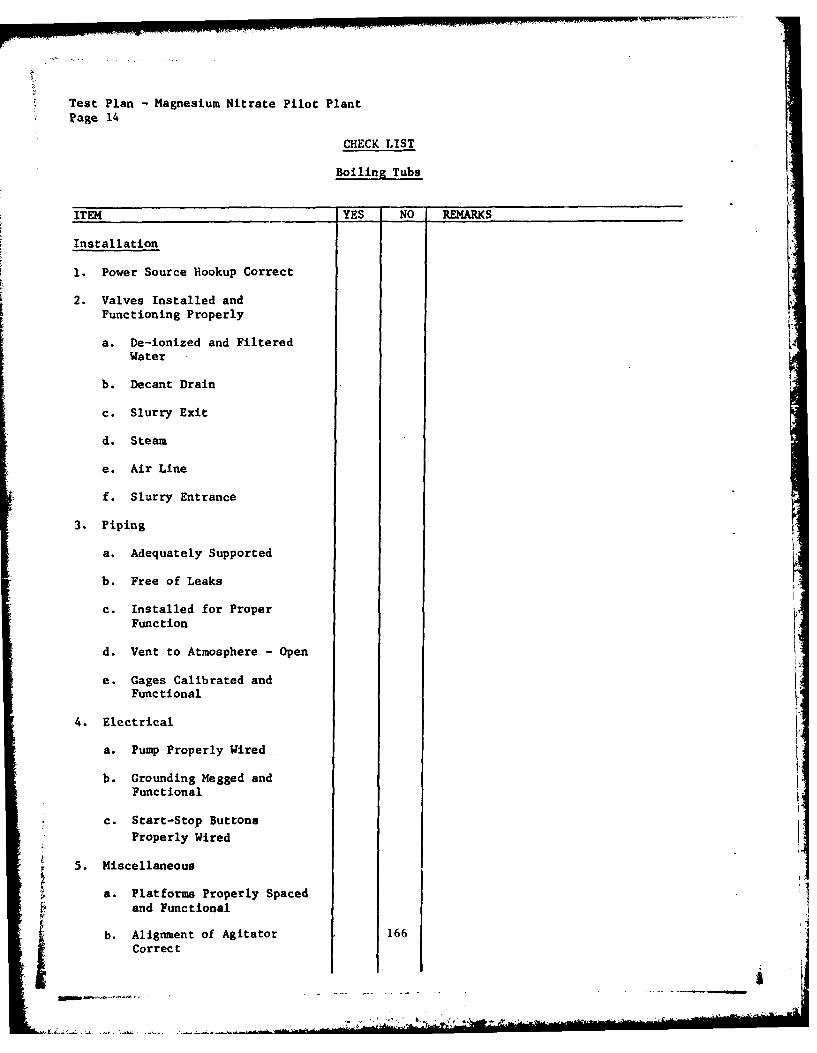
Test Plan - Magnesium Nitrate Pilot PlantPage 14
CHECK LIST
Boiling Tubs
ITEM YES NO REMARKS
Installation
1. Power Source Hookup Correct
2. Valves Installed andFunctioning Properly
a. De-ionized and FilteredWater
b. Decant Drain
c. Slurry Exit
d. Steam
e. Air Line
f. Slurry Entrance
3. Piping
a. Adequately Supported
b. Free of Leaks
c. Installed for ProperFunction
d. Vent to Atmosphere - Open
e. Gages Calibrated and
Functional
4. Electrical
a. Pump Properly Wired
b. Grounding Megged andFunctional
c. Start-Stop ButtonsProperly Wired
5. Miscellaneous
a. Platforms Properly Spaced
V and Functional
b. Alignment of Agitator 166Correct

Test Plan -Magnesium Nitrate Pilot PlantPage 15
nLow
MAGNESIUM NITRATE PROCESS
Nitration'Initiated in Nitrator Pots
Cellulose Feed
Merrick Weigh Feeder]I
I Nitration 1Salt Acid Mix[Nitrator Pots J Salt Acid Storage
Sug Feeder
NCSeparation Salt Acid Mixto
Centrifuge Recovery
ITransfer Hold
#1 Hold Tank
Filtration______________
a Eimco Filter
Viscosity Boil
I Boil Tubs
*- (s~ For Blending)
Transfer Hold
BlendTank -- 4 Product Delivery
*Size Reduction-
Attritinl l
a Transfer Hold( 167

Test Plan - Magnesium Nitrate Pilot PlantPage 16
FLOW
MAGNESIUM NITRATE PROCESS
Nitration Initiated in Attrition Mills
r Cellulose Feed 1
Merrick Weigh Feeder
Size Reduction JAttrition Mills
Nitration Salt Acid Mix
Nitrator Pots Salt Acid Storae
Slug Feeder
NC Separation Salt Acid Mixto
Centrifuge Recovery
Transfer Hold]
Slurry Tank JFiltration
Eimco Filter KViscosity Boil
Boil Tubs
L Blendin g
Blend Tank
Product
Delivery
168
1

Test Plan - Magnesium Nitrate Pilot Plant
Page 17
PHASE II.
Following the "dry run" in accordance with the check list, integration of thesystem will be evaluated by processing inert materials in conformance with theoperational flow. Cellulose and water will be utilized as the inert materialsand the ratio of water-to-cellulose will be varied as will the quantity inprocess to determine flow characteristics and capacities for handling slurries.This facility is designed and installed to provide flexibility in processtechnique with regard to utilization of the attrition mills. The designprovides capability for initiation of nitration in the attrition mills or forinitiation of- nitration in the nitrating pots with subsequent utilization ofthe mills for sizing of product following the boiling operation.
Process Evaluation When Utilizing Attrition Mills for Initiation of Nitration
Utilization of the mills for initiation of nitration during the systemsevaluation with inert materials will proceed as follows. The inert materialwill be charged into the scale feeder which, in turn, will charge preweighed
quantities into the attrition mills. Simulation of salt-acid flow to theattrition mills will be initiated. Interlocks which preclude the feeding ofmaterial into the mill unless the acid feed is operating will be checked foreffectiveness under load conditions. From the attrition mills, the materialwill be charged by gravity into the nitrators. Checks will be made to determinethe effectiveness under load of the interlocks which preclude the charging ofmaterial unless the agitators are operating and salt-acid is flowing. Fromthe nitration pots the material will be charged by gravity into the centrifugethrough the slug feeder which controls the quantity charged to ensure minimumand uniform cake thickness. Material is continuously discharged from thecentrifuge by a reciprocating internal pusher. Wash systems will be checkedunder load conditions. Slurry make-up water, which is pumped into the dischargeend of the centrifuge, will be varied to determine the desired consistency for
most efficient processing.
Following centrifuging, the slurried material will flow into NC Hold Tank #1 andfrom there pumped to the Eimco dewatering filter. The functionability of theextractor under a load condition will be checked and optimum cake thickness,wash water feed, and belt speed will be established. Material will flow bygravity to the boil tubs. From the boil tubs the material will be fed into the
blending tank and from there pumped into NC stora2e tank.
Process Evaluation When Utilizing Attrition Mills for Sizing
Utilization of the mills for sizing following the boiling operation will proceedas follows. The inert material will be charged into the scale feeder which inturn will charge preweighed quantities into the nitration pots. Checks will bemade to determine the effectiveness under load of the interlocks which precludethe charging of material into nitrators unless the agitators are operating and
169

Test Plan - Magnesium Nitrate Pilot PlantPage 18
salt-acid is flowing. From the nitration pots, the material will be charged
by gravity into the centrifuge through the slug feeder which controls the
quantity charged to ensure minimum and uniform cake thickness. Material is
continuously discharged from the centrifuge by a reciprocating internalpusher. Wash systems will be checked under load conditions. Slurry make-upwater which is pumped into the discharge end of the centrifuge will be varied
to determine desired consistency for most efficient processing. Following
centrifuging, the material will be fed into NC Hold Tank #1 and from therepumped to the Eimco dewatering filter. The functionability of the extractorunder a load condition will be checked and optimum cake thickness, wash waterfeed, and belt speed will be established. Material will flow by gravity tothe boil tubs.
Following boil, the material will be pumped into the Transfer Hold (blend) Tankand from there to the Attrition Mills for sizing. The material will flow outof the Attrition Mills into a specified boil tub and then be pumped into NCHold Tank No. 2.
The Mg(NO3)2 make-up system will be checked with water as the inert material.The performance of the agitator, metering devices, level control devices, highand low level alarms, and orifices will be observed. Load cells, gages,transmitters, and air controls for the weight indicating system will be checkedwith varying quantities of water. Detection and control systems for flow andmotor speed will be checked under load conditions. Any necessary adjustmentsto settings will be made.
Upon completion of all inert runs, the desired ratios and load capacities forthe system will be determined. Power requirements for motors under no-loadand load conditions will be determined and recorded. Any changes to equipmentand operating procedures which may have become apparent.during the inert runswill be effected.
PHASE II.
Confirmation of the process and the establishing of processing parametersutilizing live materials will begin following evaluation of the inert runresults and the incorporation of any changes deemed necessary in equipment oroperating procedures. This phase of work will consist of the manufacture ofsmall batches of nitrocellulose by the magnesium nitrate process while varyingratios, temperatures, times, etc., to determine control ranges and to establishoptimum operating conditions. Nitrocellulose will then be processed forutilization in propellant manufacture for comparison. The following studieswill be included in this phase for nitrocellulose produced by the magnesiumnitrate process:
1. Initiation of nitration in the attrition mills for correlation with
conventional continuous nitrations.
2. Separation of nitrocellulose from nitrating acid, and determination ofspent acid composition.
170

Test Plan - Magnesium Nitrate Pilot Plant
Page 19
3. Centrifuge and countercurrent wash efficiency studies.
4. Purification boiling, blending variable analysis.
5. Assessment of corrosion of the pilot size to the full size manufacturingline.
6. Correlation of the pilot size nitric acid concentrator to the full sizeconcentrator.
Evaluation of Scale Feeder Utilizing Inert Materials
1. Operation of unit interlocks will be checked so unit should not run when(a) acid mix, (b) attrition mills, or (c) nitrator agitators are notfunctioning.
2. Calibrate:
Set controller in manual mode. Adjust output to 5 milliamps (maximumspeed). Operate for warm-up at least one-half hour. Follow procedurein Merrick handbook for tare calibration and span calibration. Latteris accomplished with a test chain.
3. Operate feeder and mixed acid feed for proportional control checkout. Use
cellulose collected and weighed in boxes and liquid feed to water.
4. Check out angle drive coupling alignment.
5. Establish best hopper capacity to maintain adequate flow and minimumvariation in moisture in cellulose.
Evaluation of Scale Feeder Utilizing Live Materials
Equipment will be operated in accordance with applicable Unit Operating Procedureand General Operating Procedure. No samples will be taken for testing at thispoint.
Nitrating Acid Preparation Test Plan Utilizing Inert Materials
A. Check out equipment.
1. Check nitric acid feed line for proper valve opening.
2. Check operation of nitric acid pump.
3. Check scale tank that vents are open.
4. Check transducer electrical continuity to panel board indicator.
5. Check operation of scale tank pump.
6. Check operation of agitator.
171

Test Plan - Magnesium Nitrate Pilot PlantPage 20
B. Preoperational checkout.
1. Water check scale tank and pump.
2. Water check high and low level alarms.
3. Check temperature control.
4. Add water above low level alarm.
5. Add 50-pound calibrated weights to tank and record. Add 50-poundincrements up to 200 pounds.
6. Add water close to high level alarm position. Repeat Step 2.
Nitrating Acid Preparation Test Plan Utilizing Live Materials
1. Close discharge valve on salt/acid make--up tank.
2. Add 4,000 pounds of nitric acid (98%) to scale tank.
3. Record scale weight reading.
4. Start agitator and circulate.
5. Add 200 pounds of magnesium nitrate. Stop agitator and record weight.Circulate for 20 minutes.
6. Sample mix for laboratory analysis.
7. Add increments of 200 pounds of magnesium nitrate as in Steps 5 and 6. Thetotal number of increments will be directed by Production Engineeringengineer.
172

ITest Plan -Magnesium Nitrate Pilot PlantPage 21
Evaluation of Nitrators Utilizing Inert Materials
1. Water check nitrator for leakage.
2. Water check high and low level alarms.
3. Calibrate weir setting for desired flow rate and nitrator cycle time.
4. Operate agitators to establish optimum speed for each pot to adequatelydrown cellulose and stir.
5. Check acid feed ring with water to ensure good wetting of cellulose.
6. Operate cellulose feeder and acid flow meter to check for safety interlock.System should stop when acid flow is interrupted.
7. Measure inlet and exit temperatures of water flowing through nitrator jacket.
8. Check efficiency of air purge line.
9. Dump cellulose and water to dump tank to check efficiency of dump system.
Evaluation of Nitrators Utilizing Live Materials
Equipment will be operated in accordance with applicable Unit OperatingProcedures and General Operating Procedures. Samples of NC will be taken with
a thief from the fourth nitrating pot. Samples from nitrator will be drowned
in water.
173
....

Test Plan - Magnesium Nitrate Pilot PlantPage 22
Evaluation of Slug Feeder, Centrifuge, and Countercurrent Wash
System Utilizing Inert Materials
1. Water check slug feeder for leakage.
2. Water check high level alarm in slug feeder.
3. Operate centrifuge and set timer on slug feeder.
4. Calibrate quantity of cellulose and water fed from the slug feeder perstroke.-
5. Check efficiency of wash lines.
6. Check rate of cake buildup and uniformity of cake in the centrifuge.
7. Check efficiency of countercurrent washes.
8. Calibrate countercurrent wash sprays.
9. Check slurry tub overflow alarm.
10. Check centrifuge vibration switch operation.
11. Check use of Teflon rod to unplug feed line from slug feeder tocentrifuge.
12. Check efficiency of slurry wash lines at front of centrifuge.
13. Check consistency of slurry in slurry tank (NC Hold Tank #1)
14. Establish method of sampling slurry at entrance to slurry tank.
15. Adjust countercurrent wash lines and calibrate flow meters.
16. Measure pressure of countercurrent washes.
17. Establish method of sampling from countercurrent wash lines.
18. Check emergency shutdown procedures for the slug feeder, centrifuge,
and countercurrent wash system.
Evaluation of Slug Feeder, Centrifuge, and Countercurrent WashSystem Utilizing Live Materials
After mechanical and inert check-outs have been performed, approved PPCB fieldreview and ARMCOM safety pre-operational inspections are completed, a liveevaluation will be conducted.
Follow applicable section of Test Plan.
174
&l

Test Plan - Magnesium Nitrate Pilot PlantPage 23
Eimco Extractor Test Plan Utilizing Inert Materials
Equipment will be operated in accordance with applicable Unit OperatingProcedure and General Operating Procedure. Cellulose and water slurry will befed onto the belt at various, controlled feed rates to establish the ratecommensurate with the optimum cake thickness on the belt. In addition, filterspeed will be varb:d and the various speeds evaluated for effect on equipmentefficiency until the optimum speed is established. Wash water flow rates willbe varied and an optimum wash water rate determined. All values will berecorded as determined and incorporated into the operating instructions.
Eimco Extractor Test Plan Utilizing Live Materials
When material from No. 1 NC Hold Tank is being processed over the filterthe wash water will be sampled twice per shift and analyzed for total acid.
Evaluation of Boiling Tubs and Blending and Storage
Tanks Utilizing Inert Material,
A. Boiling Tubs
1. Close exit feed valve on boiling tub(s).
2. Close bottom drain valve.
3. Open entrance valve from Eimco filter to boiling tub(s).
4. Open vent line to atmosphere.
5. Check feed line to see that material is coming to tub. When materiallevel is above agitator blades, start agitator motor.
6. Fill tub to approximately 12 inches below the overflow line.
7. Open valve to percolator line and adjust air feed.
8. Turn on steam to tub.
9. Check tub temperature periodically until temperature reaches 96*C(consider on boil).
10. During the time of bringing to boil, check system for leaks, etc.
11. Shut off steam.
12. Shut off air to percolator.
13. Tub can be drained to the sewer or transferred to the blend tub.
14. Repeat Steps 1 through 13 for each of five tubs.
175
k.h~- -

Test Plan - Magnesium Nitrate Pilot PlantPage 24
B. Blending and Storage Tubs
1. Blending Tub
a. Close outlet feed valve.
b. Open inlet valve from boiling tubs.
c. Check inlet line to assure material is being received from boilingtub.
d. Start agitator.
e. Check for leaks, etc.
f. Material can be pumped to storage tubs, attrition mills, or drumloading.
2. Storage Tub
a. Close outlet feed valve.
b. Open inlet valves from blender tub tank.
c. Turn on gland water to blender pump.
d. Start blender pump.
e. Open blender tank outlet feed valve.
f. Check storage tank inlet line to assure that material is beingreceived.
g. Start agitator.
h. Material can be pumped to blend tank, drum loading, or otherstorage tank.
Evaluation of Boiling Tubs and Blending and StorageTanks Utilizing Live Material
After mechanical and inert check-out, approved PPCB field review and ARMCOMsafety pre-operational inspection are completed, a live evaluation will beconducted.
A. Boiling Tubs
This evaluation will be conducted to determine the optimum purificationtreatment and treatment times needed to adjust viscosity and stabilizemagnesium nitrate nitrocellulose from the prototype operation. Dataaccumulated from the bench-scale studies will be used to initiate this work.
176
. . 4

Test Plan - Magnesium Nitrate Pilot PlantPage 25
The operation of all units will be performed in accordance with theapplicable UOPs.
Analysis of data within the frame of testing may reveal the necessity
to modify this Test Plan to obtain information at differently prescribedconditions of treatment and testing.
1. Summary of Tests to Be Accomplished
a. After boiling tub is loaded, adjust acidity of material to lessthan 0.25 percent by either draining and washing or adding nitricacid. Sample for viscosity and N2.
b. Acid boil NC to adjust the viscosity of the NC and wash (boil timeselected by Production Engineering engineer).
c. Neutral boil and wash the NC twice to remove the residual acid.
Sample the NC for a complete nitrocellulose analysis.
d. Repeat Steps a through c for each boiling tub loaded.
B. Blending
1. When treatment of NC in the boiling tubs is completed and samples havebeen analyzed by the laboratory, a mathematical blend ratio of highgrade and low grade NC will be calculated.
2. The calculated weights of each type NC will be pumped to the blend tub,
agitated one hour, and sampled for a complete blend analysis (blendingtime may be increased or decreased, based on operating experience).
3. If the laboratory analysis meets the blend acceptance requirements, thematerial can be transferred to a storage tub, to containers for further
processing, or sent to waste disposal.
4. If the laboratory analyses do not meet the blend acceptance requirements,adds will be made, the blend agitated, and analyzed until the blendacceptance requirements are met. The blend then can be transferred asoutlined in Step 3.
C. Storage Tub
This tub can receive NC from the blender or from Slurry Tub #2, and cantransfer NC to the blender, attrition mills, drum loading, or #4 Boiling
Tub in C-Line NC Boiling Tub House.
177
- - - -- - - -.

Test Plan - Magnesium Nitrate Pilot PlantPage 26
Tests Required for Each NC Lot and Blend
A. Boiling Tubs (Directly After Nitration)
Tests: nitrogen, viscosity
B. Boiling Tubs (After NC Treatment)
Tests: nitrogen, solubility, viscosity, German, KI
C. Blender
Tests: nitrogen, solubility, viscosity, KI, German, Al, ash, fineness
The Magnesium Nitrate Pilot Plant facility is designed to provide flexibilityin process technique. Variation of process flow and of equipment processingparameters will be pursued in plant evaluation to establish optimum parameters.The program plan for controlled variation of processing parameters is delineatedin the test plan which will govern evaluation activities at the facility.
The need to vary parameters and process flow to properly evaluate the potentialof the Magnesium Nitrate system precludes the initiation of a conventionaltraining program, since some actions will be contingent on the results obtainedfrom previous actions. The approach to personnel training, therefore, will beaccomplished as follows. Personnel assigned to this project will thoroughlyfamiliarize themselves with equipment layout, piping arrangements, and controlconsoles. Each engineer having a primary responsibility toward procurementand installation of the individual equipment items will explain his equipmentto the group on site with regard to its process function, capabilities, alarms,and relationship to other equipment. Operating procedures will be discussedand hypothetical failures or malfunctions with appropriate corrective action(s)will be reviewed. Upon completion of this phase of training, inert runs willbe initiated for system check-out and to provide on-the-job training forpersonnel.
178

Test Plan - Magnesium Nitrate Pilot PlantPage 27
Sampling will be accomplished as specified on the chart below. All data willbe recorded and identified in a manner congruous with efficient comparisonof the effects realized from parameter variations. Data will be thoroughlyanalyzed prior to the establishment of optimum operating parameters.
Sample Location Frequency Analysis
Acid Mix 1/mix TAAcid Mix StorageSpent Acid Surge 1/shift % HNO3, % Mg(N03)2Spent Acid Storage I/shift % HNO 3 , % Mg(N03)2Recovered Acid Surge 1/shift % HNO3 , % Mg(N03)2Centrifuge Wash (Acid) 1/shift, each % 11N03, % Mg(N03)2 K
of 4 tanksBelt Wash Accumulator 1/shift TA solidsEimco Wash 2/shift TASpent Acid FinesRecovered Acid FinesBoiling Tub 2/tib TA
1/tub N2, Sol., Germ., KI,Vise., Al, Fine.
NC Blend I/blend, if N2, Sol, Germ., KI,acceptable Visc., Al, Fine., Ash
NC Storage As neededNC Hol Tank #1 As neededNC Hold Tank #2 As neededPoacher No poaching on
MCNCBoil Water Hold As neededWater FinesEimco Wash Line 2/shift60% Nitric Make-up 1/mix or tank % HNO 3Ammonium Hydroxide Make-up 6 to calibrate Then water temperature will
be used to control99% Nitric Storage l/tank delivered % HNO3Magnesium Nitrate Make-up 1/mix EDTAMagnesium Nitrate Storage 1/mix EDTARefrigeration Unit - Brine I/month % Mg(N0 3)2 ; % Zn, Cu, Sn, Fe;
SpGWater Overflow Sump Total solids; TA; ppm nitrates;
ppm Mg++Acid Overflow Sump Total solids; TA; ppm nitrates;
ppm Mg+ + !Air Samples ppm NO; ppm NOx'Noise Level DecibelsNitrogens at Nitrator 3/shift N2Nitrogens at Centrifuge 3/shift N2
179

Test Plan - Magnesium Nitrate Pilot PlantPage 28
SCALE FEEDER
Chain Setting for Water-AcidHopper Cellulose Feed, Feed, Water
Run Capacity lb/hr gal/min Meter
1 30 2.5 40:123
4 30 3.0 50:156
7 30 2.0 30:189
10 60 4.0 30:11112
13 60 5.0 40:11415
16 60 6.0 50:11718
19 100 7.0 30:12021
22 100 8.0 40:12324
25 100 9.0 50:12627
180 - ..-

Test Plan Magnesium Nitrate Pilot PlantPage 29
NITRATOR
NC Flow Cycle Range Cellulose Acid Feed Temperature,Weir Rate, Time, Agitator Feed Rate, Rate, OC Ratio,
Run Setting lb/hr min Speed lb/hr gal/min Inlet Outlet A:C
100 70 90 35 A 60 2 50 30:1
101 70 68 35 A 45 2 55 40:1
102 70 54 35 A 36 2 60 60:1
103 105 150 25 A 100 4 50 30:1
104 105 126 25 A 84 4 55 40:1
105 105 90 25 A 60 4 60 60:1
106 90 117 30 A 78 3 50 30:1
107 90 90 30 A 60 3 55 40:1
108 90 72 30 A 48 3 60 60:1
109 90 150 20 A 100 4 50 30:1
110 90 126 20 A 89 4 55 40:1
111 90 90 20 A 60 4. 60 60:1
I1
i8

Test Plan - Magnesium Nitrate Pilot PlantPage 30
ATTRITION MILLS (Nitration Initiation)
Acid
Ratio Feed Cellulose Cycle
Controller Rate, Feed Rate, Ammeter Reading Weir Time, Nitrogen,
Run Setting PM lb/hr Start Operating Setting min percent
1 40:1 Top2 40:1 Top3 40:1 Top
4 30:1 Top5 30:1 Top6 30:1 Top
7 40:1 Bottom8 40:1 Bottom9 40:1 Bottom
10 30:1 Bottom11 30:1 Bottom12 30:1 Bottom
13 40:1 Halfway14 40:1 Halfway15 40:1 Halfway
16 30:1 Halfway17 30:1 Halfway18 30:1 Halfway
182
&

Test Plan- Magnesium Nitrate Pilot PlantPage 31
ATTRITION MILLS (Particle Size Uniformity)
Run Ammeter Reading Quantity of Material Total Sizing Time
Each To be established 600 or 1,000 gallons To be establishedBoiling to meet a fineness of slurry relativeTub of 90-110 ml to two tub sizes
183
~~~~~~~~~~~~~~~~~~~~~~~~.. ..... ..............-'"... "- ' i - h..... I .......... .... "............... -J

Test Plan -Magnesium Nitrate Pilot PlantPage 32
S 0
H-4 0
0
-4 I
.0 -4 0
F-4 0 CCA)
0)
-0
.0 0
0d
,4' 4! 00ri 0 0 "a
P4
-4 0 i-
cj.9
-4 $
4) l .
E-4
418

Test Plan - Magnesium Nitrate Pilot PlantPage 33
POACHING
Weight Soda Ash Tub Boil TimesRun of NC Add Temperature #1 #2 #3 #4
There is no poaching treatment on the Magnesium Nitrate system.
185

Test Plan -Magnesium Nitrate Pilot PlantPage 34
MANUFACTURE OF 60% OR 30% NITRIC ACID
Make-upTank Water 99% HN03 Agitation Tank Approx. % HNO 3 By
Run Weight Weigtht Weight Time Temperature % HN03 Analysis
1 5 30
2 10 30
3 15 30
4 20 30
5 25 30
6 5 60
7 10 60
8 15 60
9 20 60
10 25 60
186

Test Plan -Magnesium Nitrate Pilot PlantPage 35
4
0 ;>
01
- 4I
j
4-)fL
14
ca 4
141
fn -44 -4
-40
C'~ e 1' 4 1.4
S
187

t
Test ?Ian -Magnesium Nitrate Pilot Plant
Page 36
INERT CELLULOSE
LIQUID AND CELLULOSE SCALE FEEDER
Pulp -100-108; Lint - 200-208; Same conditions.
Run Ratio Cellulose Feed, pph H90O, pph
100 50:1 50 2,500
101 50:1 100 5,000
102 50:1 150 7,500
103 35:1 50 1,650
104 35:1 100 3,500
105 35:1 150 5,250
106 20:1 50 1,000
107 20:1 100 2,000
108 20:1 150 3,000
188

Test Plan - Magnesium Nitrate Pilot PlantPage 37
EIMCO EXTRACTOR -INERT
Vac uumFeed Rate, Cake Filter Wash Water Total Acid of Reading,
R~un percent Thickness Speed, rpm Flow Rate Wash Water in(,h/Hg
1 1.0 2, 5, 10, 15 5, max
2 20 (belowatmospheric)
3 30
4 40
5 s0
6 60
7 70
8 80
9 90
10 100
189

Test Plan -Magnesium Nitrate Pilot PlantPage 38
0 w
r. 41MO) > -V0 4 w
W0 &J $
Cd flU 01
o QF5.
0 Z ~L~U ~ I A I A I
-' -n n %n n Hn n Hn LA
en
,q t - -;r It Go 0 IT IT -'t
S0 C14C4 cl C4 C4 C-4 C C4 C14 0
0
H- 0Q 0 ni I 0 0 IA IA IA IA Ln IA IAto ca 1- cl -4 H4 1- -4 -4 -
4 r4 -4
0 PU b
01 0
z u
CA (U k1000
0~W II" IA IA IA IA IA Ln Ln In IA-4 r1 r-4 H -4 -4 4 -4 .-4 H
O 4H
U :-4 r-4HH H
(JO] -MI tn 0 0 tn .tn .LA IA In In
to Cl
NJ A0 U V1 01 %w4 b0 c 44 -
190

Test Plan -Magnesium Nitrate Pilot PlantPage 39
0 .
04
(n4
00 50
00
'.4
a4-
U : j$-H. 0 4 % o-T % 1 %> 1- iol -
U ,ocolol
w- (J-,SM
S'*-4'0 (' .0 0 0 (' ~ '0 0 0 0 ' . '0
W. 00 041:
A 41
E-4
41 0 0 0 0 0 0 0 0 0 0 0 0
4 4 W 4 41 4 4j 4j .j 4 4 1
V-1494 1.
419

Test Plan -Magnesium Nitrate Pilot PlantPage 40
60
03
V4 f -f 4 ('4 C' 4 t's C11 C14 ('4 ('4 ( ('4 C11 C14 (a 4 ('4
04 1
0
0 0
1.4 al)I
OcO
43 0
0
14 0
4-4
>
o0 )0
I 4 0 40
u 0
0)
.- 4 -t i D r- G %0 - n )%
~ 03190
3:,q ,-

Test Plan -Magnesium Nitrate Pilot PlantPage 41
94
04
a.I..
E- H H -H -
%0 C3)l
014 cn c
0 0 0 0
t-4 -q 4.)-
E-4 tobO u
0* 41 0 0 i I
A ~ " 4
-4
0 0 0 0OQ IQ M4 M
4 ~
1.4 1i 1.4 193
.~ 0 '~x

Test Plan -Magnesium Nitrate Pilot PlantPage 42
pol
Ad
0)
...-4-
(-44 44-C
0
a) C... 19 C C O 9O ( 0 0 0c
:3 ": 3 3A :
00 4.4C4 4 e
$4.
w04 0 0 0 0 0 0 00 0 0
4400! 00 0 00 0000 0 0 0 0u . &j4 j4 1" 1A 14
V-4~ V- q r4 4 - -
:19

Test Plan M agnesium Nitrate Pilot PlantPage 43
oo w
C- 4 21 0o
:9 'a a 0 a00c 00 0. l . U i
4. 'a4 14. 1- 4 4'4 .
u0 IA IA 0
14
$4 0
(=2 0) 'a
'1 ..4 r4 .4 .I - 4 -0~ Q
(-4 r.. a0 410)U
w(1 W .4 00 Q
4j H. 0 0 - - -w* 4-I 54 -I
A inIn IA Un &n 0 0Ha ~ - -4 .- 4 1-4 Nl -4
4.4 (An'a
U
1954
A -A,

Test Plan Kag.,sLum Nitrate Pilot Plat
Paz "'44
A A
SA 0 33M .213 A0 .0 :I A
2t 2 ...
"0 a, .4. . .So~~j u4' ui~t
~~~~~~~~ 0~C t. 0 ~ ~
I R lag~46
(S x p 3-32 us oOtt l atbe)(1 t314 atba
.4196

APPENDIX D .
Pilot Plant Operating Procedures On File AtRadford Army Amunition Plant
j 197

APPENDIX I)
PILOT PLANT OPERATING PROCEDURES ON FILE AT RADFORD ARMYAMMUNITION PLANT
Item Procedure Number Title
1 4-26-40 General Operating Procedure
2 4-26-40(A) General Sampling Procedure
3 4-26-40(B) Carrier Refrigeration Unit Operation
4 4-26-40(C) Operating Procedure for the Manufacture ofDemineralized Water K
5 4-26-40(D) Manufacture of 30 Percent Ammonium Hydroxide
6 4-26-40(E) Manufacture of 60 Percent or 30 Percent "Nitric Acid '
7 4-26-40(F) Nitration Scale Feeder
8 4-26-40(G) Nitrating Acid Feed and Nitrator
9 4-26-40(H) Operation of S-8 Baker Perkins Continuous
Centrifuge
10 4-26-40(1) Dewatering Nitrocellulose Prior toViscosity Boil
11 4-26-40(J) Boiling Tub Operations
12 4-26-40(K) Poaching Operations
13 4-26-40(L) Attrition Mills - Sizing of Cellulose Nitratedby the Mixed Acid Method
14 4-26-40(M) Blending Operations
15 4-26-40(N) Operating Procedure for the Recovery ofMagnesium Nitrate and Nitric Acid from theProcess Stream
16 4-26-40(0) Merco Rotary Strainer
17 4-26-40(P) Durco Tubular Filters
18 4-26-40(Q) Operating Procedure for Operation of the C. W.Thomson Communication System
19 4-26-40(R) Use of the M.S.A. Demand Air Mask
20 4-26-40(S) Operation of Dumbwaiter
j 198

APPENDIX E
A..ME.Coded Presure Vesels
(Documentation on file at RAAP)
____ ____ ____ ___. . . .* .~ .% .. ..... .. .... ..

-a. -; 17 . ., m . - .4 4 4 4- 4-5- 4 .*
4 .s . f4 0 -
b. 0 V4. 7 . 7z" 2 x . z .. N . N . N
40 to to in .w .'A w. 4 US vs n
al0 W W
s.-Z 6 40 6 4 . 6
a p *3 ay o-a a~. al *I
4c4
1 4.4 ~ ~ ~ ~ ~ j 4 4NN 4 4 0 a
ad a
-4 -4
-t4
c. 00 . o
o~~D u'a . . 4 - 4 4'
w * 0 . 'A w 000ac.0 0 6 0 0 4. o 0
M. 6 .42
-~ ~~~~ .~ : 0 wU-o~-- 0 0 0 44 C I
fA k -4 5. - ; 4 4- 60 60on A A A, Iwo ~ 6
A--4a a% aoP a . a4 C4 M 06.43 -3 P"
A. ~ a a. a 200a

DISTRIBUTION LIST
CommanderUS Army Armament Research and
Development CommandATTN: DRDAR-CG
DRDAR-LCDRDAR-LCM-E (6)DRDAR- LC4- SDRDAR- SFDRDAR-TSS (5)DRDAR-LCU-PDRDAR-CLDRDAR- LCA
Dover, NJ 07801
CommanderUS Army Materiel Development and
Readiness CommandATTN: DRCDE
DRCMTDRC PADRCPP-IDRCP IDRCSG
5001 Eisenhower AvenueAlexandria, VA 22333
CommanderUS Army Armament Materiel
Readiness CommnandATTN: DRSAR-IR (2)
DRSAR- IRCDRSAR-IRH (2)DRSAR- P13*DRSAR-LC (2)DRSAR-ASF (2)DRSAR-SF (3)
Rock Island, IL 61299
DirectorUS Army Industrial Base Engineering ActivityAtTTN: DRXIB-MTRock Island, IL 61299
f 201

CommanderUSDRC Installations and Services AgencyATTN: DRCIS-RI-IU
DRCIS-RI-ICRock Island, IL 61299
ChairmanDept of Defense Explosives Safety BoardHoffman Bldg 1, Room 856C2461 Eisenhower AvenueAlexandria, VA 22331
Project Manager for Munitions ProductionBase Modernization and ExpansionUS Army Materiel Development and
Readiness CommandATTN: DRCPM-PBM-LA
DRCPM-PBM-T-SFDRCPM-PBM-EP (2)
Dover, NJ 07801
DirectorBallistic Research LaboratoryARRADCOMATTN: DP!)AR-BLE (2)Aberdeen Proving Ground, MD 21010
Defense Documentation Center (12)Cameron StationAlexandria, VA 22314
CommanderUS Army Construction Engineering
Research LaboratoryAfTN: DERL-ERChampaign, IL 61820
Office, Chief of EngineersATTN: DAEN-MCZ-EWashington, DC 20314
US Army Engineer District, HuntsvilleATTN: Construction Division-HAD-ED (2)PO Box 1600 West StationHuntsville, AL 35807
202

CommanderIndiana Army Ammunition PlantATTN: SARIN-OR (2)
SARIN-SFCharlestown, IN 47111
CommanderKansas Army Ammunition PlantATTN: SARKA-CEParsons, KS 67537
CommanderLone Star Army Ammunition PlantATTN: SARLS-COTexarkana, TX 57701
CommanderMilan Army Ammunition PlantATTN: SARMI-COMilan, TN 38358
CommanderRadford Army Ammunition PlantATTN: SARRA-IE (6)Radford, VA 24141
CommanderBadger Army Ammunition PlantATTN: SARBA-CE (2)Baraboo, WI 53913
CommanderHolston Army Ammunition PlantATTN: SARHO-COKingsport, TN 37662
CommanderIowa Army Ammunition PlantATTN: SARIO-AMiddletown, IA 52638
CommanderJoliet Army Ammunition PlantATTN: SARJO-COJoliet, IL 60436
203
.1" *

-
CommanderLonghorn Army Ammunition PlantATTN: SARLO-XCMarshall, TX 75670
CommanderLouisiana Army Ammunition PlantATTN: SARLA- XCShreveport, LA 71102
CommanderNewport Army Ammunition PlantATTN: SARNE-CONewport, IN 47966
CommanderPine Bluff ArsenalATTN: SARPB-XOPine Bluff, AR 71601
CommanderSunflower Ammunition PlantATTN: SARSU-CODeSoto, KS 66018
CommanderVolunteer Army Ammunition PlantATTN: SARVO-XCChattanooga, TN 34701
Weapon System Concept Team/CSLATTN: DRDAR-ACWAberdeen Proving Ground, MD 21010
Technical LibraryATTN: DRDAR-CLJ-LAberdeen Proving Ground, MD 21010
Technical LibraryATTN: DRDAR-TSB-SAberdeen Proving Ground, MD 21005
Benet Weapons LaboratoryTechnical LibraryATTN: DRDAR-LCB-TLWatervliet, NY 12189
204

t
CommanderUS Army Armament Materiel
Readiness CommandATTN: DRSAR-LEP-LRock Island, IL 61299
US Army Materiel Systems Analysis ActivityATTN: DRXSY-MPAberdeen Proving Ground, MD 21005
205