US-APWR Defense-in-Depth and Diversity Coping Analysis
83
DEFENSE-IN-DEPTH AND DIVERSITY COPING ANALYSIS MUAP-07014-NP(R4) Mitsubishi Heavy Industries, LTD. US-APWR Defense-in-Depth and Diversity Coping Analysis August 2011 © 2011 Mitsubishi Heavy Industries, Ltd. All Rights Reserved Non Proprietary Version
Transcript of US-APWR Defense-in-Depth and Diversity Coping Analysis
DEFENSE-IN-DEPTH AND DIVERSITY COPING ANALYSIS MUAP-07014-NP(R4)
Mitsubishi Heavy Industries, LTD.
US-APWR
Defense-in-Depth and Diversity
Coping Analysis
August 2011
© 2011 Mitsubishi Heavy Industries, Ltd. All Rights Reserved
Non Proprietary Version

DEFENSE-IN-DEPTH AND DIVERSITY COPING ANALYSIS MUAP-07014-NP(R4)
Mitsubishi Heavy Industries, LTD.
Revision History
Revision Date Page (Section) Description
0 December 2007 All Original issued
1 June 2008 All
Revised to incorporate additional clarification contained in MHI RAI response letters UAP-HF-08070 and UAP-HF-08099. Typographical, grammatical, and editorial changes were also made. The detailed description of this revision is described below.
3-2 (3.2.3)
Revised to incorporate additional clarification contained in MHI RAI response letters UAP-HF-08070 and UAP-HF-08099.
3-5 to 3-7 (3.3 to 3.4)
Revised to incorporate additional clarification contained in MHI RAI response letters UAP-HF-08070 and UAP-HF-08099. Description of Human Factor Engineering is added.
4-1 to 4-2 (4.1)
Revised to incorporate additional clarification contained in MHI RAI response letters UAP-HF-08070 and UAP-HF-08099.
4-7
(4-5) Description of Evaluation Models is added.
4-8 (4.6)
Revised to incorporate additional clarification contained in MHI RAI response letters UAP-HF-08070 and UAP-HF-08099.
5-1 to 5-38
(5.0) As above
7-1
(7.0) New references 6 through 10 are added.
ii to ix Typographical, grammatical, and editorial changes
were made.
viii to ix New acronyms are added.
1-1
(1.0) Typographical, grammatical, and editorial changes were made.

DEFENSE-IN-DEPTH AND DIVERSITY COPING ANALYSIS MUAP-07014-NP(R4)
Mitsubishi Heavy Industries, LTD.
Revision Date Page (Section) Description
2-1
(2.0) As above
3-1 to 3-5
(3.0) As above
4-3 to 4-6
(4.3 to 4.4)As above
6-1
(6.0) As above
7-1
(7.0) As above
2 December 2009
All Typographical, grammatical, and editorial changes were made.
3-2
(3.2) Revised to add descriptions based on ASAI 5-9 in Safety evaluation report for MUAP-07006-P, Revision 2
3-5
(3.3) As above
3-9 to 3-12
(3.5) As above (new addition)
5-29 to 5-
30 (5.4)
As above
5-31 to 5-
33 (5.5)
As above
5-33 to 5-
46 (5.6)
As above
4-8
(4.5) Revised to add descriptions on an evaluation model for LBLOCA
3-5
(3.3) Revised to delete leak detection
3-5 to 3-7
(3.4) Revised to add descriptions based on ASAI 5-10 in Safety evaluation report for MUAP-07006-P, Revision 2
3-8
(3.4) Revised to delete leak detection alarms in table 3.4-1.
5-40 to 5-
46 (5.6)
Revised to add descriptions based on ASAI 5-10 in Safety evaluation report for MUAP-07006-P, Revision 2
7-1
(7.0) New references 11 through 13 are added.
DEFENSE-IN-DEPTH AND DIVERSITY COPING ANALYSIS MUAP-07014-NP(R4)
Mitsubishi Heavy Industries, LTD.
Revision Date Page (Section) Description
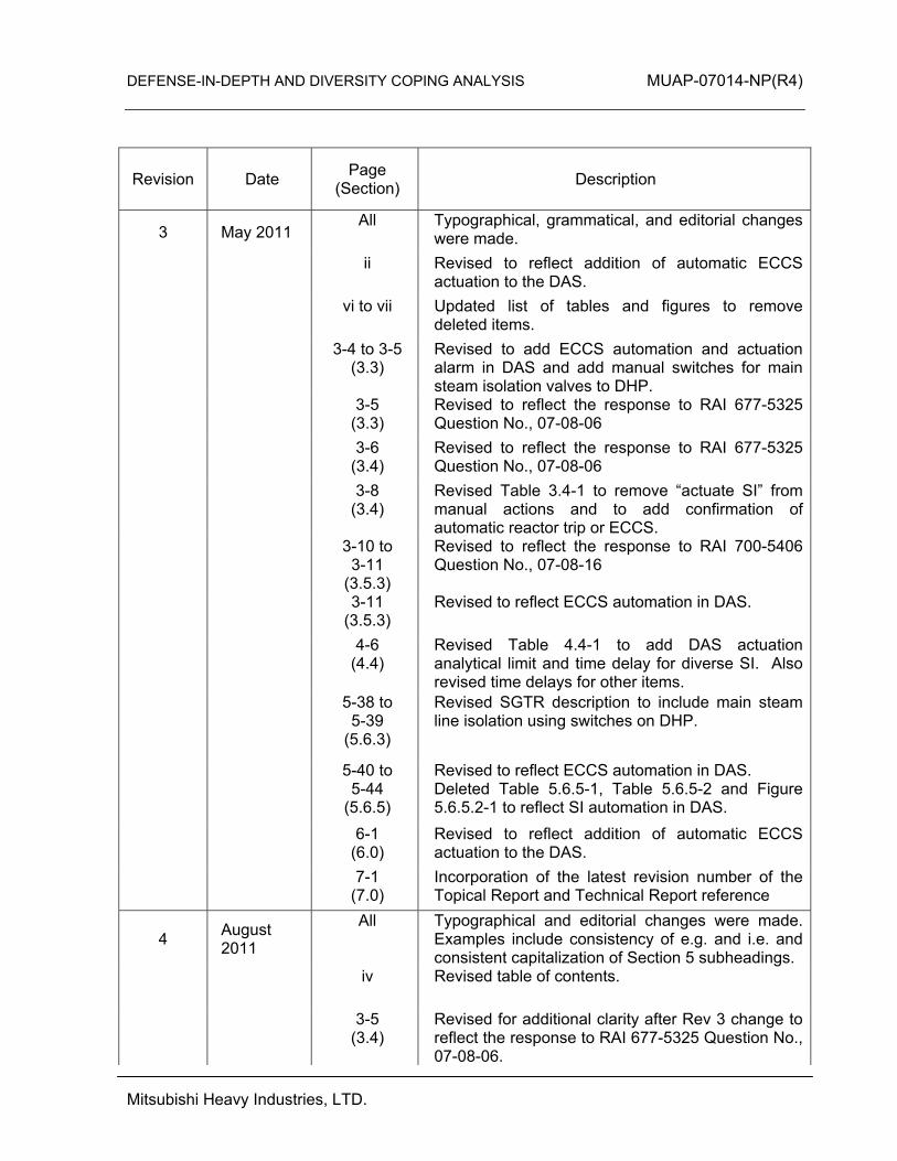
3 May 2011 All Typographical, grammatical, and editorial changes
were made.
ii
Revised to reflect addition of automatic ECCS actuation to the DAS.
vi to vii Updated list of tables and figures to remove
deleted items.
3-4 to 3-5
(3.3) Revised to add ECCS automation and actuation alarm in DAS and add manual switches for main steam isolation valves to DHP.
3-5
(3.3) Revised to reflect the response to RAI 677-5325 Question No., 07-08-06
3-6
(3.4) Revised to reflect the response to RAI 677-5325 Question No., 07-08-06
3-8
(3.4) Revised Table 3.4-1 to remove “actuate SI” from manual actions and to add confirmation of automatic reactor trip or ECCS.
3-10 to
3-11 (3.5.3)
Revised to reflect the response to RAI 700-5406 Question No., 07-08-16
3-11
(3.5.3) Revised to reflect ECCS automation in DAS.
4-6
(4.4) Revised Table 4.4-1 to add DAS actuation analytical limit and time delay for diverse SI. Also revised time delays for other items.
5-38 to
5-39 (5.6.3)
Revised SGTR description to include main steam line isolation using switches on DHP.
5-40 to
5-44 (5.6.5)
Revised to reflect ECCS automation in DAS. Deleted Table 5.6.5-1, Table 5.6.5-2 and Figure 5.6.5.2-1 to reflect SI automation in DAS.
6-1
(6.0) Revised to reflect addition of automatic ECCS actuation to the DAS.
7-1
(7.0) Incorporation of the latest revision number of the Topical Report and Technical Report reference
4 August 2011
All Typographical and editorial changes were made. Examples include consistency of e.g. and i.e. and consistent capitalization of Section 5 subheadings.
iv Revised table of contents.
3-5
(3.4) Revised for additional clarity after Rev 3 change to reflect the response to RAI 677-5325 Question No., 07-08-06.
DEFENSE-IN-DEPTH AND DIVERSITY COPING ANALYSIS MUAP-07014-NP(R4)
Mitsubishi Heavy Industries, LTD.
Revision Date Page (Section) Description
3-8 (Tab. 3.4-1)
Revised so that last column of 3rd row is consistent with bullets in Section 3.4 and last column of 4th row reflects manual actions associated with LOCA events.
3-10 to 3-
12 (3.5.3)
Revised to describe manual defeat diverse actuation from DAS.
4-1
(4.1) Added additional clarification regarding the treatment of external hazards with a concurrent CCF.
4-6
(4.6 and Tab. 4.4-1)
Revised for clarity.
5-1
(5.0) Editorial clarification for consistency with changes to event-specific dose portions of Section 5.
5-41
(5.6.5) Revised for clarity
7-1
(7.0) Updated reference 10 revision number.
DEFENSE-IN-DEPTH AND DIVERSITY COPING ANALYSIS MUAP-07014-NP(R4)
Mitsubishi Heavy Industries, LTD. i
© 2011 MITSUBISHI HEAVY INDUSTRIES, LTD.
All Rights Reserved This document has been prepared by Mitsubishi Heavy Industries, Ltd. (“MHI”) in connection with the U.S. Nuclear Regulatory Commission’s (“NRC”) licensing review of MHI’s US-APWR nuclear power plant design. No right to disclose, use or copy any of the information in this document, other that by the NRC and its contractors in support of the licensing review of the US-APWR, is authorized without the express written permission of MHI. This document contains technology information and intellectual property relating to the US-APWR and it is delivered to the NRC on the express condition that it not be disclosed, copied or reproduced in whole or in part, or used for the benefit of anyone other than MHI without the express written permission of MHI, except as set forth in the previous paragraph. This document is protected by the laws of Japan, U.S. copyright law, international treaties and conventions, and the applicable laws of any country where it is being used.
Mitsubishi Heavy Industries, Ltd. 16-5, Konan 2-chome, Minato-ku Tokyo 108-8215 Japan

DEFENSE-IN-DEPTH AND DIVERSITY COPING ANALYSIS MUAP-07014-NP(R4)
Mitsubishi Heavy Industries, LTD. ii
Abstract This technical report describes Mitsubishi Heavy Industries’ (MHI’s) approach to demonstrate defense-in-depth and diversity (D3) coping analysis for the instrumentation and control (I&C) systems applied to the US-APWR plant. This approach is based on the design information described in MHI’s topical reports for digital I&C systems and the Design Control Document (DCD) for the US-APWR design certification application. The D3 coping analysis utilizes best estimate assumptions in accordance with U.S. Nuclear Regulatory Commission (NRC) guidance to analyze each anticipated operational occurrence (AOO) or a postulated accident (PA) described in the DCD Chapter 15 safety analysis. This report describes how the diverse actuation system (DAS) copes with a common cause failure (CCF) in the digital safety system that occurs concurrent with each event. In this analysis, all of the safety functions of the digital safety system are assumed to be disabled by a CCF. Also, the mitigating functions of the control systems that use the same digital platform are assumed to be disabled by the same CCF. On the other hand, the DAS provides diverse automatic reactor/turbine trip, diverse emergency feedwater actuation, and diverse safety injection actuation functions which are not impaired by the postulated CCF. The DAS also provides manual actuation functions and plant parameter monitoring functions which can be used to cope with CCFs. Available components and plant conditions assumed in this analysis are established in a best estimate manner considering beyond design basis situations. The D3 coping analysis is performed to confirm that the US-APWR DCD Chapter 15 safety analysis events (AOOs/PAs) are successfully mitigated by the DAS and related components even if a CCF occurs during the assumed plant conditions. The analysis / evaluation is conducted in terms of the pressure boundary integrity, core coolability, and radiation release based on the CCF acceptance criteria.
DEFENSE-IN-DEPTH AND DIVERSITY COPING ANALYSIS MUAP-07014-NP(R4)
Mitsubishi Heavy Industries, LTD. iii
Table of Contents
List of Tables ··············································································································vi
List of Figures ·············································································································vii
List of Acronyms ·········································································································viii
1.0 INTRODUCTION ·································································································1-1
2.0 CODES AND STANDARDS ················································································2-1
2.1 Code of Federal Regulations ···········································································2-1
2.2 Standard Review Plan ·····················································································2-1
3.0 BASIS OF I&C SYSTEM DESIGN FOR D3 COPING ANALYSIS·······················3-1
3.1 Objective and General Consideration ······························································3-1
3.2 Failure Modes of the Digital I&C System ·························································3-1
3.2.1 Effect of a CCF within the Digital Platform ················································3-1
3.2.2 Failure Mode of the Protection and Safety Monitoring System ·················3-2
3.2.3 Failure Mode of the Plant Control and Monitoring System························3-2
3.3 Diverse Actuation System Functions ·······························································3-3
3.4 Operator Actions ······························································································3-5
3.5 Analysis for Partial CCF Conditions·································································3-9
3.5.1 Partial Actuation ·························································································3-9
3.5.2 Conflicting Commands ···············································································3-9
3.5.3 Erroneous Signals ······················································································3-10
3.5.4 Failure to Actuate with False Indications····················································3-12
4.0 D3 COPING ANALYSIS ······················································································4-1
4.1 Best Estimate Assumptions of the Plant System Conditions ···························4-1
4.2 Events to be Analyzed ·····················································································4-3
4.3 Acceptance Criteria··························································································4-3
4.4 Diverse Actuation System Assumed in the D3 Coping Analysis······················4-6
4.5 Evaluation Models····························································································4-7
4.6 Event Evaluation Methods ···············································································4-8
5.0 D3 COPING ANALYSIS RESULTS·····································································5-1
5.1 Increase in Heat Removal by the Secondary System······································5-1
5.1.1 Decrease in Feedwater Temperature as a Result of Feedwater System Malfunctions ······························································································5-1

DEFENSE-IN-DEPTH AND DIVERSITY COPING ANALYSIS MUAP-07014-NP(R4)
Mitsubishi Heavy Industries, LTD. iv
5.1.2 Increase in Feedwater Flow as a Result of Feedwater System Malfunctions ······························································································5-2
5.1.3 Increase in Steam Flow as a Result of Steam Pressure Regulator Malfunction ································································································5-3
5.1.4 Inadvertent Opening of a Steam Generator Relief or Safety Valve···········5-3
5.1.5 Steam System Piping Failures Inside and Outside of Containment··········5-4
5.2 Decrease in Heat Removal by the Secondary System ····································5-4
5.2.1 Loss of External Load················································································5-4
5.2.2 Turbine Trip ·······························································································5-10
5.2.3 Loss of Condenser Vacuum ······································································5-10
5.2.4 Closure of Main Steam Isolation Valve ·····················································5-10
5.2.5 Steam Pressure Regulator Failure ····························································5-10
5.2.6 Loss of Non-Emergency AC Power to the Station Auxiliaries ···················5-10
5.2.7 Loss of Normal Feedwater Flow································································5-11
5.2.8 Feedwater System Pipe Break Inside and Outside Containment ·············5-12
5.3 Decrease in Reactor Coolant System Flow Rate·············································5-13
5.3.1 Loss of Forced Reactor Coolant Flow Including Trip of Pump Motor ········5-13
5.3.1.1 Partial Loss of Forced Reactor Coolant Flow ·····································5-13
5.3.1.2 Complete Loss of Forced Reactor Coolant Flow ································5-20
5.3.2 Flow Controller Malfunctions ·····································································5-20
5.3.3 Reactor Coolant Pump Rotor Seizure ·······················································5-20
5.3.4 Reactor Coolant Pump Shaft Break ··························································5-21
5.4 Reactivity and Power Distribution Anomalies ··················································5-22
5.4.1 Uncontrolled Control Rod Assembly Withdrawal from a Subcritical or Low Power Startup Condition································································5-22
5.4.2 Uncontrolled Control Rod Assembly Withdrawal at Power ·······················5-22
5.4.3 Control Rod Misoperation (System Malfunction or Operator Error)···········5-28
5.4.4 Startup of an Inactive Loop or Recirculation Loop at an Incorrect Temperature ······························································································5-29
5.4.5 Flow Controller Malfunction Causing an Increase in BWR Core Flow Rate ··································································································5-29
5.4.6 Inadvertent Decrease in Boron Concentration in the Reactor Coolant System·······································································································5-29
5.4.7 Inadvertent Loading and Operation of a Fuel Assembly in an Improper Position······································································································5-31
5.4.8 Spectrum of Rod Ejection Accidents ·························································5-31

DEFENSE-IN-DEPTH AND DIVERSITY COPING ANALYSIS MUAP-07014-NP(R4)
Mitsubishi Heavy Industries, LTD. v
5.4.9 Spectrum of Rod Drop Accidents in a BWR··············································5-31
5.5 Increase in Reactor Coolant Inventory·····························································5-31
5.5.1 Inadvertent Operation of Emergency Core Cooling System that Increases Reactor Coolant Inventory ························································5-31
5.5.2 Chemical and Volume Control System Malfunction that Increases Reactor Coolant Inventory·········································································5-32
5.6 Decrease in Reactor Coolant Inventory ···························································5-33
5.6.1 Inadvertent Opening of a PWR Pressurizer Pressure Relief Valve or a BWR Pressure Relief Valve····································································5-33
5.6.2 Radiological Consequences of the Failure of Small Lines Carrying Primary Coolant Outside Containment ······················································5-34
5.6.3 Radiological Consequences of Steam Generator Tube Failure ················5-36
5.6.4 Radiological Consequences of Main Steam Line Failure Outside Containment (BWR) ··················································································5-40
5.6.5 Loss-of-Coolant Accidents Resulting from Spectrum of Postulated Piping Breaks within the Reactor Coolant Pressure Boundary ·················5-40
5.6.5.1 Large Break Loss-of-Coolant Accident (LBLOCA) ·····························5-40
5.6.5.2 Small Break Loss-of-Coolant Accident (SBLOCA) ·····························5-43
6.0 CONCLUSION·····································································································6-1
7.0 REFERENCES ····································································································7-1

DEFENSE-IN-DEPTH AND DIVERSITY COPING ANALYSIS MUAP-07014-NP(R4)
Mitsubishi Heavy Industries, LTD. vi
List of Tables
Table 3.4-1 Comparison of Operator Actions for Design Basis Events 3-8
Table 4.3-1 CCF Acceptance Criteria (BTP 7-19) 4-5
Table 4.3-2 ATWS Acceptance Criteria (SRP 15.8) 4-5
Table 4.3-3 Acceptance Criteria in this Report 4-5
Table 4.4-1 DAS Actuation Analytical Limit and Time Delays Assumed for D3 Coping Analysis
4-6
Table 5.4.6-1 Inadvertent Decrease in Boron Concentration in the Reactor Coolant System in the case that a CCF in the PSMS also Affects All of the Control Functions of the PCMS
5-30
Table 5.5.2-1 Chemical and Volume Control System Malfunction that Increases Reactor Coolant Inventory in the case that a CCF in the PSMS also Affects All of the Control Functions of the PCMS
5-33
Table 5.6.2-1 Radiological Consequences of the Failure of Small Lines Carrying Primary Coolant Outside Containment in the case that a CCF in the PSMS also Affects All of the Control Functions of the PCMS
5-35
Table 5.6.3-1 Radiological Consequences of Steam Generator Tube Failure in the case that a CCF in the PSMS also Affects All of the Control Functions of the PCMS
5-37

DEFENSE-IN-DEPTH AND DIVERSITY COPING ANALYSIS MUAP-07014-NP(R4)
Mitsubishi Heavy Industries, LTD. vii
List of Figures
Figure 5.2.1-1 Reactor Power versus Time Loss of Load Event
5-6
Figure 5.2.1-2 RCP Outlet Pressure versus Time Loss of Load Event
5-7
Figure 5.2.1-3 Pressurizer Safety Valve Flow Rate versus Time Loss of Load Event
5-8
Figure 5.2.1-4 RCS Average Temperature versus Time Loss of Load Event
5-9
Figure 5.3.1.1-1 RCS Total and Loop Volumetric Flow versus Time Partial Loss of Forced Reactor Coolant Flow
5-15
Figure 5.3.1.1-2 Reactor Power versus Time Partial Loss of Forced Reactor Coolant Flow
5-16
Figure 5.3.1.1-3 RCS Pressure versus Time Partial Loss of Forced Reactor Coolant Flow
5-17
Figure 5.3.1.1-4 RCS Average Temperature versus Time Partial Loss of Forced Reactor Coolant Flow
5-18
Figure 5.3.1.1-5 DNBR versus Time Partial Loss of Forced Reactor Coolant Flow
5-19
Figure 5.4.2-1 Reactor Power versus Time Uncontrolled Control Rod Assembly Withdrawal at Power
5-24
Figure 5.4.2-2 RCS Pressure versus Time Uncontrolled Control Rod Assembly Withdrawal at Power
5-25
Figure 5.4.2-3 RCS Average Temperature versus Time Uncontrolled Control Rod Assembly Withdrawal at Power
5-26
Figure 5.4.2-4 DNBR versus Time Uncontrolled Control Rod Assembly Withdrawal at Power
5-27
Figure 5.6.3-1 Differences in Manual Action between an SGTR Event With and Without a Concurrent CCF
5-39
Figure 5.6.5.1-1 Peak Cladding Temperature (PCT) versus Time Large Break Loss-of-Coolant Accident (LBLOCA)
5-42

DEFENSE-IN-DEPTH AND DIVERSITY COPING ANALYSIS MUAP-07014-NP(R4)
Mitsubishi Heavy Industries, LTD. viii
List of Acronyms
ac alternating current AOO anticipated operational occurrence ARP alarm response procedure ATWS anticipated transients without scram BOC beginning-of-cycle BTP Branch Technical Position C/V containment vessel CCF common cause failure COL Combined License CRDM control rod drive mechanism CVCS chemical and volume control system D3 defense-in-depth and diversity DAS diverse actuation system DCD Design Control Document DHP diverse HSI panel DNB departure from nucleate boiling DNBR departure from nucleate boiling ratio ECCS emergency core cooling system EFW emergency feedwater EFWS emergency feedwater system EOC end-of-cycle EOP emergency operating procedure ESF engineered safety features HFE Human Factor Engineering HSI human system interface HZP hot zero power I&C instrumentation and control
ITAAC Inspection, Test, Analysis and Acceptance Criteria
LBLOCA large break loss-of-coolant accident LOCA loss-of-coolant accident M/G motor generator MCR main control room MHI Mitsubishi Heavy Industries, Ltd NRC U.S. Nuclear Regulatory Commission NSSS nuclear steam supply system PA postulated accident PCMS plant control and monitoring system PRA probabilistic risk assessment
DEFENSE-IN-DEPTH AND DIVERSITY COPING ANALYSIS MUAP-07014-NP(R4)
Mitsubishi Heavy Industries, LTD. ix
PSMS protection and safety monitoring system PWR pressurized water reactor RCCA rod cluster control assembly RCP reactor coolant pump RCPB reactor coolant pressure boundary RCS reactor coolant system RTS reactor trip system SAR safety analysis report SBLOCA small break loss-of-coolant accident SGTR steam generator tube rupture SI safety injection SRP Standard Review Plan SSC structure, system, and component VDU Visual Display Unit

DEFENSE-IN-DEPTH AND DIVERSITY COPING ANALYSIS MUAP-07014-NP(R4)
Mitsubishi Heavy Industries, LTD. 1-1
1.0 INTRODUCTION
The purpose of this technical report is to describe Mitsubishi Heavy Industries (MHI) approach to demonstrate defense-in-depth and diversity (D3) coping analysis of the instrumentation and control (I&C) systems of the US-APWR plant. MHI prepared this technical report to support D3 design information in the Design Control Document (DCD) for the US-APWR plant design certification application. The following documents describe the (1) system design approach to prevent common cause failures (CCFs) in the high integrity digital I&C system for the US-APWR plant, and (2) analysis and design approach for the diverse actuation system (DAS) as the countermeasure for the effect of CCFs. US-APWR DCD Chapter 7 “Instrumentation and Controls” summarizes the relevant design information from these topical reports.
• MHI Topical Report MUAP-07004, “Safety I&C System Description and Design Process” (Reference 1).
• MHI Topical Report MUAP-07005, “Safety System Digital Platform – MELTAC” (Reference 2).
• MHI Topical Report MUAP-07006, “Defense-in-Depth and Diversity” (Reference 3). • MHI Topical Report MUAP-07007, “HSI System Description and HFE Process”
(Reference 4). This technical report provides performance analyses that demonstrate how functions of the DAS cope with a CCF in the digital I&C system concurrent with an anticipated operational occurrence (AOO) or a postulated accident (PA) based on best-estimate assumptions. Applicable codes and standards and conformance to them are described in Section 2. Failure mode analysis of digital I&C systems and available DAS functions used in the coping analysis are described in Section 3. The basis for the coping analysis including best-estimate assumptions and results of the analysis for each event are described in Section 4 and Section 5, respectively.
DEFENSE-IN-DEPTH AND DIVERSITY COPING ANALYSIS MUAP-07014-NP(R4)
Mitsubishi Heavy Industries, LTD. 2-1
2.0 CODES AND STANDARDS
This section identifies compliance to applicable codes, standards and conformance with applicable U.S. Nuclear Regulatory Commission (NRC) guidance, as appropriate. Unless specifically noted, the latest version issued on the date of this document is applicable. 2.1 Code of Federal Regulations
10 CFR 50.62 (Reference 7) provides requirements for reduction of risk from anticipated transients without scram (ATWS) events.
The DAS has diverse turbine trip and emergency feedwater (EFW) actuation capability as required for ATWS mitigation. The DAS also has a diverse reactor trip function which interrupts electrical power to the control rod drive mechanisms (CRDM) by tripping the motor-generator set supplying power to the CRDM magnetic gripper coils. The DAS design is diverse from the protection system, with the exception of sensors, which are shared with the protection system. This report shows that the DAS can mitigate the anticipated operational occurrences assuming the safety system fails to trip the reactor. 2.2 Standard Review Plan
Branch Technical Position (BTP) 7-19 (Reference 8) provides guidance for the evaluation of diversity and defense-in-depth in digital computer-based instrumentation and control systems. The DAS design and analysis approach used to comply with this Standard Review Plan (SRP) BTP 7-19 is described in MUAP-07006. This technical report supplements the design description by providing the best-estimate coping analysis results that demonstrate that the DAS is capable of mitigating the DCD Chapter 15 postulated AOOs and PAs concurrent with a CCF. The acceptance criteria used in this coping analysis are based on acceptance criteria stated in BTP 7-19.

DEFENSE-IN-DEPTH AND DIVERSITY COPING ANALYSIS MUAP-07014-NP(R4)
Mitsubishi Heavy Industries, LTD. 3-1
3.0 BASIS OF I&C SYSTEM DESIGN FOR D3 COPING ANALYSIS
3.1 Objective and General Consideration
The objective of the D3 coping analysis is to show that the DAS is able to mitigate the plant response against postulated events considering a CCF in the digital I&C system and to meet the requirements of BTP 7-19. BTP 7-19 provides guidance on the NRCs position on D3 for advanced light-water reactors. This D3 coping analysis is based on the following points from BTP 7-19. Point 1: The applicant/licensee should assess the D3 of the proposed I&C system to
demonstrate that vulnerabilities to CCFs have been adequately addressed. Point 2: In performing the assessment, the vendor or applicant/licensee should analyze
each postulated CCF for each event that is evaluated in the accident analysis section of the safety analysis report (SAR) using best-estimate or SAR Chapter 15 analysis methods. The vendor or applicant/licensee should demonstrate adequate diversity within the design for each of these events.
The remainder of Section 3 describes the (1) failure modes of digital I&C systems, (2) available diverse mitigation means assumed in the coping analysis, and (3) requirements for operator actions. Section 4 establishes the assumptions and methodology established to evaluate the response of the beyond-design-basis events concurrent with a CCF. The effects of a CCF on plant safety for each postulated event are analyzed in Section 5 using the best-estimate analysis assumptions and methodologies described in Section 4. 3.2 Failure Modes of the Digital I&C System
3.2.1 Effect of a CCF within the Digital Platform
The effect of a CCF on the MELTAC digital platform is discussed in MUAP-07006. A highly conservative design approach is applied to the MELTAC digital platform in order to assure high integrity of the software. Important characteristics of this design approach are summarized as follows.
• No use of commercial off-the-shelf software, including the operating system.
• No use of software and hardware interrupts in software execution.
• All the software modules are executed during a fixed cycle time in a predefined order. This means that there is neither selection of executed modules nor changes in the order of execution.
• No dynamic allocation of memory. This means that all the memory used to execute safety functions are accessed in every execution cycle.

DEFENSE-IN-DEPTH AND DIVERSITY COPING ANALYSIS MUAP-07014-NP(R4)
Mitsubishi Heavy Industries, LTD. 3-2
These design attributes assure that the MELTAC digital platform does not change its software execution path and memory access regardless of whether the plant conditions represent normal operation or accident conditions. Therefore, the most probable cause of such a CCF is where hidden failures which disable the safety functions have accumulated among the redundant systems and finally cause the loss of the entire safety function. These failures remain hidden, and therefore coexist when the system is required to actuate for design basis event mitigation. 3.2.2 Failure Mode of the Protection and Safety Monitoring System
The protection and safety monitoring system (PSMS) encompasses all safety related I&C systems in the plant. Per the discussion in MUAP-07006, a CCF may affect all the digital controllers in the PSMS. Therefore, it is most conservative to assume that the CCF disables all the safety functions in the PSMS; this is the basis of the most conservative D3 coping analysis provided in Section 5. Section 3.5 discusses how the analysis in Section 5 bounds all partial CCF conditions (i.e., conditions where a software defect results in CCF of only a subset of PSMS functions). Detectable failures that actuate spurious signals can be adequately treated and repaired before all of the redundant portions of the safety system are affected by the same or common cause. Alternatively, it is possible that failures by the same or common cause may remain inside the safety systems without any indication of malfunction. As time proceeds, redundant portions of the safety system could be affected by the same or common cause, and finally the safety system loses its ability to mitigate the event even though there is sufficient redundancy. Although these scenarios are unlikely to occur, it is theoretically possible that all of the safety functions of the PSMS could be disabled by the CCF in this way. As a result, in D3 coping analysis all of the safety functions are assumed to be disabled before an event occurs. On the other hand, spurious actuation of safety functions other than the initiating events in the Chapter 15 safety analysis is not assumed in the D3 coping analysis, because the type of software failure resulting in spurious actuation is self-announcing and not caused by the plant accident conditions. 3.2.3 Failure Mode of the Plant Control and Monitoring System
The plant control and monitoring system (PCMS) consists of many subsystems which contain digital controllers and have many kinds of plant control functions which can be used to regulate the plant normal operation and can be used to mitigate the consequences of transients. The D3 coping analysis assumes that the PCMS operates during the event in one of the two following ways:
DEFENSE-IN-DEPTH AND DIVERSITY COPING ANALYSIS MUAP-07014-NP(R4)
Mitsubishi Heavy Industries, LTD. 3-3
• The case where the PSMS CCF also affects all of the control functions of the PCMS. This scenario would result due to a defect that exists in software that is common to PSMS and PCMS.
• The case where the PCMS is unaffected by the CCF. This scenario would result due to a defect that exists in software that is unique only to PSMS.
These assumptions are different from the DCD Chapter 15 safety analysis, which examines each individual control system to define the worst case aggravating condition (i.e., normal automatic control or manual control) for each initiating event. The two CCF cases discussed above represent theoretical bounding CCF conditions. Since the PCMS uses instrumentation signals that are transmitted from the PSMS for the major nuclear steam supply system (NSSS) control systems described in Section 7.7 of the DCD (e.g., pressurizer pressure control, pressurizer level control, steam generator level control, etc.), it is most likely that a software defect that results in a CCF in the PSMS would also result in a CCF of the PCMS. This CCF would adversely affect these NSSS control systems, and therefore, would be detected by operators prior to any specific AOO or PA. For a software defect to remain undetected, it would need to only affect the RPS and ESFAS actuation and control functions of the PSMS, but not the input processing and data communication processing functions, which are needed to transmit the signals to the PCMS for NSSS control. Although this is highly incredible, it is the worst case assumption made for the bounding case where the PCMS is unaffected by the CCF. 3.3 Diverse Actuation System Functions
The DAS has following functions to provide a diverse means to cope with a CCF.
• Diverse automatic actuation
• Diverse manual actuation
• Diverse monitoring Detailed functions and design information are described in MUAP-07006 and Chapter 7 of the US-APWR DCD. A summary of these three functions is provided below to assist in the subsequent discussion of the coping analysis. Diverse Automatic Actuation The DAS has diverse automatic actuation functions to shut down the reactor and to achieve secondary system core heat removal. (1) Diverse reactor trip/Diverse turbine trip/Diverse main feedwater isolation
The following initiation signals trip the reactor by opening the motor-generator set supply breakers to interrupt electrical power to the CRDM gripper coils. Turbine trip and closure of all of the main feedwater regulation valves are also actuated by the same signals.

DEFENSE-IN-DEPTH AND DIVERSITY COPING ANALYSIS MUAP-07014-NP(R4)
Mitsubishi Heavy Industries, LTD. 3-4
• High pressurizer pressure (2-out-of-4 voting logic of the 4 pressurizer pressure channel signals)
• Low pressurizer pressure (2-out-of-4 voting logic of the 4 pressurizer pressure channel signals)
• Low steam generator water level (2-out-of-4 voting logic from a single steam generator water level channel signal per steam generator)
(2) Diverse emergency feedwater actuation
The following initiation signal automatically actuates all of the EFW pumps. The steam generator blowdown isolation valves are closed by the same signal to ensure that the EFW flow to the steam generators will provide sufficient level for heat removal.
• Low steam generator water level (2-out-of-4 voting logic from a single steam generator water level channel signal per steam generator)
(3) Diverse emergency core cooling system actuation
The following initiation signal automatically actuates all of the safety injection pumps.
• Low-low pressurizer pressure (2-out-of-4 voting logic of the 4 pressurizer pressure channel signals)
Diverse Manual Actuation The Diverse HSI Panel (DHP), which is located in the main control room (MCR), contains conventional switches for manual actuation of the systems and the components which are required to cope with a CCF.
• Manual reactor trip / Turbine trip / Main feedwater isolation: 1 switch (manually actuate the diverse reactor trip function described above)
• Manual emergency feedwater actuation: 1 switch (manually start all of the emergency feedwater pumps)
• Manual emergency core cooling system (ECCS) actuation: 1 switch (manually start all of the safety injection pumps)
• Manual containment isolation: 1 switch (manually close all major containment isolation valves at once)
• Manual operation of emergency feedwater control valves: 4 switches (manually control an emergency feedwater control valve for each steam generator)
• Manual operation of main steam depressurization valves: 4 switches (manually control a main steam depressurization valve for each steam generator)

DEFENSE-IN-DEPTH AND DIVERSITY COPING ANALYSIS MUAP-07014-NP(R4)
Mitsubishi Heavy Industries, LTD. 3-5
• Manual operation of safety depressurization valve: 1 switch (manually control a safety depressurization valve)
• Manual operation of main steam isolation valves: 4 switches (manually control a main steam isolation valve for each steam line)
Diverse Monitoring The DHP contains conventional indicators and alarms located in the MCR for monitoring plant parameters and initiating operator actions to cope with a CCF. DHP indicators are provided for the following monitored variables.
• Wide-range neutron flux
• Pressurizer pressure
• Reactor coolant pressure wide range
• Reactor coolant cold leg temperature (Tcold) (for each loop)
• Pressurizer water level
• Steam generator water level (for each steam generator)
• Main steam line pressure (for each steam generator)
• Containment pressure The following DHP alarms are provided as unique alarms to initiate operator action based on Special Event Emergency Operating Procedures (EOPs) in the case of events with a CCF.
• DAS automatic actuation (summary audible, with first out indication of initiating input condition)
• Main steam line radiation (N-16)
• Diverse emergency core cooling system actuation Additionally, the DHP contains a High-high steam generator water level alarm for each steam generator to assist the operator in monitoring ongoing plant conditions while operating from the DHP. 3.4 Operator Actions
The events which require operator actions to meet the acceptance criteria in the D3 coping analyses are as follows. The corresponding D3 coping analysis results section is provided in parenthesis following the event description. Note that the operator actions required to achieve a cold shutdown condition and operate long term cooling after event mitigation are outside the scope of this evaluation as described in Section 4.1.
DEFENSE-IN-DEPTH AND DIVERSITY COPING ANALYSIS MUAP-07014-NP(R4)
Mitsubishi Heavy Industries, LTD. 3-6
• Inadvertent Decrease in Boron Concentration in Reactor Coolant System (Section 5.4.6)
• Chemical and Volume Control System Malfunction that Increases Reactor Coolant Inventory (Section 5.5.2)
• Radiological Consequences of Steam Generator Tube Failure (Section 5.6.3)
• Spectrum of Rod Ejection Accidents (Section 5.4.8)
• Radiological Consequences of the Failure of Small Lines Carrying Primary Coolant Outside Containment (Section 5.6.2)
• Loss-of-Coolant Accident Resulting from Spectrum of Postulated Piping Breaks within the Reactor Coolant System Boundary (Section 5.6.5)
For the events except the above events, operators may detect the event from expected PCMS alarms. Operators will detect the CCF from the DAS reactor trip and corresponding DHP alarms. Operators will then use Special Event EOPs to achieve and maintain hot shutdown conditions. For these events (not identified above) there are no credited manual actions needed to mitigate events. Manual actions for event mitigation with a concurrent CCF are based on simple Special Event EOPs which cover mitigation actions and subsequent actions which include symptom based monitoring and recovery. Based on the unique automatic actuation alarms (including first out indication), the operator starts taking actions using the indications and controls on the diverse HSI panel (DHP). For the US-APWR the specific DHP indications and controls are defined in Tables 7.8-2 and 7.8-4 of the DCD. After the reactor is tripped, either automatically or by manual actions, operators will monitor and control the plant as follows:
・ Verify both the reactor and the turbine have tripped (through neutron flux and main steam line pressure indications on the DHP)
・ Verify sufficient emergency feedwater into each steam generator (through steam generator water level indications on the DHP)
・ Control EFW flow rate using the DHP Tcold indicator and EFW control valves Although most events will be mitigated or terminated upon completion of “CCF event specific actions”, the procedures direct the operator to continue to monitor the event, and all critical safety functions to ensure that plant conditions stabilize. As described in MUAP-07006, any operator actions credited in the D3 coping analysis are justified based on a Human Factor Engineering (HFE) evaluation (Reference 11 and 12). As shown in Table 3.4-1 the list of required operator tasks associated with the mitigation of an event with a concurrent CCF is considerably simplified compared with the tasks necessary for mitigating events without a concurrent CCF. In addition, during the Combined License (COL) stage, when EOPs have been developed and a simulator is available, the ability to take these manual operator actions will be

DEFENSE-IN-DEPTH AND DIVERSITY COPING ANALYSIS MUAP-07014-NP(R4)
Mitsubishi Heavy Industries, LTD. 3-7
validated. During plant operation, ongoing operator training and human performance monitoring will support the required action times. The DHP has only about 10 alarm tiles and for any event the alarms that would be activated at the same time are limited to only a few. Therefore, it is reasonable to conclude that the time for the operator to react to the DHP prompting alarm is short and the potential for human error rate to omit the alarm is very low (Reference 11 and 12). Response to the DHP prompting alarm is classified as a typical rule-based task, since operators will follow paper-based EOPs/Alarm Response Procedures (ARPs) dedicated for the DHP. Tasks for all credited time critical manual operator actions will be analyzed according to the Special Event procedures to confirm adequate time margin between time available and time required. This margin will also be validated in the integrated HSI validation tests. The training program will be developed to ensure the operators are well trained. Validation and operator training are encompassed with HFE Inspection, Test, Analysis and Acceptance Criteria (ITAACs). The “Total Time Required” shown in each table of Section 5 is based on the sequence of operator actions defined in the table. The time required for each operator action is based on conservative engineering judgment. Actions employing local controls are assumed to require 30 minutes after entry into the procedure that directs these actions. For this stage in the US-APWR design, this is a reasonable assumption, since local actions do not require special clothing or access to equipment in restricted locations. These times will be verified using table top walkthroughs, and validated using a high fidelity dynamic simulator. Verification and validation activities will employ senior reactor operators and HFE experts. Event specific descriptions of the required operator actions and any subsequent HFE evaluations of the sequence of manual actions for the specific events listed above are provided in the event-specific subsection of Section 5.

DEFENSE-IN-DEPTH AND DIVERSITY COPING ANALYSIS MUAP-07014-NP(R4)
Mitsubishi Heavy Industries, LTD. 3-8
Table 3.4-1 Comparison of Operator Actions for Design Basis Events
AOOs/PAs without CCF AOOs/PAs with CCF Alarms to be acknowledged
Reactor trip or ECCS actuation first-out alarms
DHP alarms
Parameters to be confirmed
・ Pressurizer Pressure ・ Reactor Coolant Pressure ・ Containment Pressure ・ Pressurizer Water Level ・ A~D-Reactor Coolant Average
Temperature ・ A~D-Steam Generator Water Level
(Narrow Range) ・ A~D-Steam Generator Pressure ・ A~D-Main Feedwater Flow Rate ・ A~D-Main Steam Flow Rate ・ Intermediate Neutron Flux ・ Containment Sump Flow ・ Containment Air Cooler
Condensate Flow Rate ・ Containment Airborne Particulate
Radioactivity ・ Containment Airborne Gaseous
Radioactivity ・ Condenser Vacuum Pump Exhaust
Line Radiation ・ Steam generator blowdown
radiation
・ Pressurizer Pressure ・ Reactor Coolant Pressure ・ Containment Pressure ・ Pressurizer Water Level ・ A~D-Reactor Coolant Cold Leg
Temperature (Wide Range) ・ A~D-Steam Generator Water Level
(Narrow Range) ・ Wide Range Neutron Flux
Status to be confirmed
・ All Reactor Trip Breaker Open ・ All Control Rods Drop ・ ECCS Sequence Components
Activated
・ Reactor Trip on DHP ・ Turbine Trip on DHP ・ SG Water Level on DHP ・ ECCS Activated on DHP
Required Action ・ Manual Reactor Trip ・ Actuate ECCS (if required) ・ Isolate broken steam generator ・ Terminate charging flow ・ Terminate dilution flow ・ Isolate Broken Lines (CVCS
Letdown Line or RCS Sample Lines)
・ Manual Reactor Trip ・ Isolate broken steam generator ・ Terminate charging flow ・ Terminate dilution flow ・ Isolate Broken Lines (CVCS
Letdown Line or RCS Sample Lines)
・ Local actuation of containment spray

DEFENSE-IN-DEPTH AND DIVERSITY COPING ANALYSIS MUAP-07014-NP(R4)
Mitsubishi Heavy Industries, LTD. 3-9
3.5 Analysis for Partial CCF Conditions
Section 5 of this document provides the D3 coping analysis for all Chapter 15 events with the following two digital CCF scenarios:
1. Chapter 15 event with a concurrent CCF that disables the complete PSMS and the complete PCMS.
2. Chapter 15 event with a concurrent CCF that disables the complete PSMS, but does not affect the PCMS.
These two digital CCF scenarios are analyzed because there are three categories of software used within the PSMS and PCMS:
1. Software that is common to both systems - A CCF in this software would lead to condition 1 above.
2. Software that is unique to the PSMS - A CCF in this software would lead to condition 2, above.
3. Software that is unique to the PCMS - A defect in this software does not affect the PSMS. Therefore, these failures are not addressed within this D3 Coping Analysis.
However, in addition to the complete failure of the PSMS (as analyzed for conditions 1 and 2, above), ISG-02 states: … the evaluation of failure modes as a result of software CCF should include the possibility of partial actuation and failure to actuate with false indications… “Partial Actuation” and “Failure to Actuate with False Indications” are analyzed as follows: 3.5.1 Partial Actuation
In considering CCFs that could result in partial actuation of the PSMS, it is important to first emphasize that Section 5 demonstrates that the mitigating actions, available through equipment that is not affected by the CCF (e.g., the DAS and local controls), are sufficient to cope with all Chapter 15 events, under the condition that there is no contribution from the PSMS. Therefore, it can be concluded that any actuation of the PSMS can only improve the results of the D3 coping analysis, as long as that actuation does not adversely affect the diverse mitigating functions that are credited in the Section 5 analysis. Therefore, the only partial CCFs of concern are those that result in failure of the credited function(s) of the PSMS and failure of the credited diverse backup function(s). The scenarios that have the potential to lead to this adverse interaction are analyzed in the following subsections. 3.5.2 Conflicting Commands
If the partial CCF results in the PSMS generating or maintaining a previously generated undesirable (or non-safe state) control command (e.g., close valve), there is the potential to block the backup system’s ability to put that component in the safe state that is credited in the D3 coping analysis (e.g., open valve). To prevent this adverse interaction, the priority logic within the PSMS Power Interface Module ensures the DAS can perform its credited safety function (e.g., open valve). This priority logic is a hardware based design that does not employ software. Therefore, it is not susceptible to the PSMS software CCF.

DEFENSE-IN-DEPTH AND DIVERSITY COPING ANALYSIS MUAP-07014-NP(R4)
Mitsubishi Heavy Industries, LTD. 3-10
3.5.3 Erroneous Signals
Since the DAS includes blocking logic, which prevents DAS actuation if the PSMS actuates correctly, the DAS functions could be blocked by erroneous signals (i.e., signals indicating that the protection system has actuated correctly, when it actually has not). To avoid any potential for erroneous signals that may be generated by the digital CCF, the signals used to block the DAS actuation are obtained from sources that are not affected by the digital CCF, as follows: (1) Reactor Trip, Turbine Trip and Main Feedwater Isolation The DAS automatic reactor trip, automatic turbine trip and automatic main feedwater isolation functions are blocked only when the DAS receives signals hardwired directly from the reactor trip breaker and low turbine emergency oil pressure signals (i.e., down stream of the postulated digital CCF) in the condition that the pressurizer pressure is above the P-11 setpoint. The diverse actuation signal from DAS is manually defeated in the condition that the pressurizer pressure below the P-11 setpoint during normal shutdown operations. These hardwired signals indicate that the required number of circuit breakers and turbine emergency trip oil pressure trip signal have correctly actuated. If either actuation is unsuccessful, the DAS will generate backup reactor trip, backup turbine trip and backup main feedwater isolation signals. For example, if there is a partial CCF in the PSMS that affects only reactor trip, the PSMS will actuate turbine trip and main feedwater isolation, and the DAS will actuate reactor trip. Similarly, if there is a partial CCF in the PSMS that affects only turbine trip, the PSMS will actuate reactor trip and main feedwater isolation, and the DAS will actuate turbine trip. A partial CCF could also result in failure of the main feedwater isolation function of the PSMS, but may not affect the reactor trip and turbine trip functions of the PSMS. For this scenario, the DAS will receive successful reactor trip and turbine trip feedback, which will result in blocking all three functions, including DAS actuation of main feedwater isolation. To accommodate this partial CCF condition, the main feedwater isolation valves are diversely closed by both the PSMS (by actuating binary pilot solenoids) and PCMS (by actuating modulating electro-pneumatic positioners). Since this failure only affects the main feedwater function of the PSMS (not all functions), the software defect cannot be in the PSMS Basic Software (which is common to all functions). Instead, the software defect must be in PSMS software that is unique to the main feedwater isolation function (i.e., the solenoid component control Application Software, or the portion of the MELTAC Basic Software that executes those unique binary solenoid application functions). Therefore, the PCMS main feedwater isolation function, which controls the valve’s modulating positioners, is not adversely affected, because it does not rely on the same Application Software or Basic Software used to actuate binary solenoids, as in the PSMS. (2) EFW Actuation The DAS automatic actuation of emergency feedwater is blocked only when the DAS receives signals hardwired directly from the motor driven EFW pump switchgear and the turbine driven EFW pump control valves (i.e., down stream of the postulated digital CCF) in the condition that the pressurizer pressure is above the P-11 setpoint. The diverse actuation signal from DAS is manually defeated in the condition that the pressurizer

DEFENSE-IN-DEPTH AND DIVERSITY COPING ANALYSIS MUAP-07014-NP(R4)
Mitsubishi Heavy Industries, LTD. 3-11
pressure below the P-11 setpoint during normal shutdown operations. These hardwired signals indicate that the required number of EFW pumps have correctly actuated. If the PSMS EFW pump actuation is unsuccessful, the DAS will generate backup EFW actuation signals. It is noted, that there are also valves in the EFW flow lines. Therefore, it could be postulated that the EFW pumps would start as expected, but a partial CCF could prevent opening the valves. However, this failure does not need to be considered, because during normal plant operating conditions, the EFW flow line valves are open. If these valves are closed for any reason, this state can be detected by an indication in MCR. This will prompt correct positioning of these valves to their required normally open position, prior to a Chapter 15 event. Since BTP-19 allows the use of best estimate methods, only normal pre-event plant conditions are considered in the D3 Coping Analysis. It is also noted, that spurious closure of these valves due to CCF, concurrent with a design basis event, does not need to be considered, as discussed in Section 5.5 of MUAP-07006 and Section 4 of DI&C Interim Staff Guidance 02. (3) Main Steam Line Radiation (N-16) Alarm The DAS N-16 high radiation alarm is credited to prompt manual action to mitigate the SGTR event. This alarm is blocked only when the DAS receives signals hardwired directly from an output of the PCMS, which generates the PCMS N-16 alarm in the condition that the pressurizer pressure is above the P-11 setpoint. The diverse actuation signal from DAS is manually defeated in the condition that the pressurizer pressure below the P-11 setpoint during normal shutdown operations. These hardwired signals indicate that the required PCMS N16 alarm has correctly actuated. If the PCMS N-16 alarm actuation is unsuccessful due to CCF, the alarm processor will not generate this output and the DAS will generate a backup N-16 alarm. For the SGTR event, there are no PSMS automated actions credited in the Chapter 15 analysis, and no DAS automated actions credited in the D3 coping analysis. Therefore, if the PCMS correctly generates the N-16 alarm, operators are prompted to take the mitigating actions credited in the Chapter 15 analysis. (4) High-High Steam Generator Water Level Alarm The DAS high-high steam generator water level alarm is not credited to prompt diverse manual actions for any event in the D3 coping analysis. The alarm is provided only to support operator tasks after diverse mitigation actions are prompted by other alarms. This alarm is blocked only when the DAS receives signals hardwired directly from the reactor trip breaker (i.e., down stream of the postulated digital CCF) in the condition that the pressurizer pressure is above the P-11 setpoint. The diverse actuation signal from DAS is manually defeated in the condition that the pressurizer pressure below the P-11 setpoint during normal shutdown operations. These hardwired signals indicate that the required number of circuit breakers have correctly actuated. If the reactor trip actuation is successful, the manual actions credited in the D3 coping analysis are not needed. This is true regardless of any partial CCF conditions that may block other PSMS functions. Therefore, it is appropriate to block the DAS high-high steam generator water level prompting alarm.

DEFENSE-IN-DEPTH AND DIVERSITY COPING ANALYSIS MUAP-07014-NP(R4)
Mitsubishi Heavy Industries, LTD. 3-12
(5) Emergency Core Cooling System Actuation The DAS low-low pressurizer pressure ECCS automatic actuation is credited to mitigate LOCA events. This automatic actuation is blocked only when the DAS receives signals hardwired directly from the safety injection (SI) pump switchgear (i.e., down stream of the postulated digital CCF) in the condition that the pressurizer pressure is above the P-11 setpoint. The diverse actuation signal from DAS is manually defeated in the condition that the pressurizer pressure below the P-11 setpoint during normal shutdown operations. These hardwired signals indicate that the required number of SI pumps have correctly actuated. If the SI pump actuation is unsuccessful, due to a CCF, the DAS actuates ECCS automatically. It is noted, that there are also valves in the SI flow lines. Therefore, it could be postulated that the SI pumps would start as expected, but a partial CCF could prevent opening the valves. However, this failure mode does not need to be considered, because during normal plant operating conditions, the SI flow line valves are open. If these valves are closed for any reason, this state can be detected by an indication in MCR. This will prompt correct positioning of these valves to their required normally open position, prior to a Chapter 15 event. Since BTP-19 allows the use of best estimate methods, only normal pre-event plant conditions are considered in the D3 coping analysis. It is also noted, that spurious closure of these valves due to CCF, concurrent with a design basis event, does not need to be considered, as discussed in Section 5.5 of MUAP-07006 and Section 4 of DI&C Interim Staff Guidance 02. 3.5.4 Failure to Actuate with False Indications
Conditions that result in failure of a credited PSMS function and erroneous indication that the function did actually actuate are precluded, as follows: • If actuation and indication rely on a common software block (either directly or indirectly),
they will both fail together (i.e., no actuation and no indication). • If actuation and indication rely on different software blocks, per NUREG 6303 only one
block is assumed to fail in the CCF analysis. o If the actuation block fails, there is no actuation but correct indication of no
actuation. For this condition, the operator will take diverse manual actions. o If the indication block fails, there is correct actuation but erroneous indication of
no actuation. For this condition, the operator will take diverse manual actions. Therefore, there is no potential for failure of the PSMS to actuate, with conflicting indications that inhibit operator response. It is also noted that if the PSMS fails to actuate, DAS prompting alarms will be generated as discussed above. Since single failures cannot generate spurious DAS prompting alarms, operators will be trained to respond to DAS prompting alarms, regardless of other control room indications. The DAS alarms will prompt operators to initiate special event EOPs for CCF conditions.
DEFENSE-IN-DEPTH AND DIVERSITY COPING ANALYSIS MUAP-07014-NP(R4)
Mitsubishi Heavy Industries, LTD. 4-1
4.0 D3 COPING ANALYSIS
4.1 Best Estimate Assumptions of the Plant System Conditions
To perform the D3 coping analysis, assumptions for plant and equipment conditions have been established. In contrast to some of the conservative assumptions made in the DCD Chapter 15 safety analyses, BTP 7-19 permits the use of best-estimate analysis methods for the D3 coping analyses. The following items describe the relaxed assumptions utilized in the best-estimate D3 coping analyses. Reactor Operating Mode The DCD Chapter 15 safety analysis considers worst case operating conditions, which include low power and refueling conditions. In the D3 coping analysis, the plant is assumed to be operating in Mode 1 at rated power. This assumption covers the majority of the operational time interval of the plant which means this assumption covers the most likely plant conditions for events with concurrent CCF. Single Failure In the D3 coping analysis, no single failure is assumed for the structures, systems, and components (SSCs) used to mitigate the consequences of the postulated events. This means that in the best-estimate analysis, all mitigating equipment (exclusive of the CCF) is assumed to operate as designed. Despite this, maintenance (unavailability) of certain mitigating SSCs during power operation is assumed in the D3 coping analysis if on-line maintenance of that equipment is allowed by the Technical Specifications. Power Source In the D3 coping analysis, offsite electrical power is assumed to be available during the mitigating period of the events, except for the loss of offsite power initiating event. External Hazards In the D3 coping analysis, external hazards such as fire, flooding, seismic and other external hazards are also considered. D3 related equipment is located in reactor building and is designed to protect external hazards. As described in a technical report, "US-APWR Probabilistic Risk Assessment" (MUAP-07030-P), the risk due to external hazards with a concurrent CCF is not significant. Control Systems The D3 coping analysis assumes that the PCMS operates during the event in one of the two following ways:
• The case where the PSMS CCF also affects all of the control functions of the PCMS.
• The case where the PCMS is unaffected by the CCF.
DEFENSE-IN-DEPTH AND DIVERSITY COPING ANALYSIS MUAP-07014-NP(R4)
Mitsubishi Heavy Industries, LTD. 4-2
In some cases, such as to test a plant system or component during plant operation, the operating mode of a control system may be changed to an unusual mode under administrative control by the plant operators. For example, the rod control system may be in manual control mode during power operation for the purpose of performing nuclear instrumentation calibration or secondary system operational testing. In this case, the time duration of these specific operations is limited and the condition of the plant and operation of I&C systems are being carefully monitored by the plant operator. Events with a concurrent CCF occurring during these administrative operational modes will be easily detected and the operator can take mitigative action. Therefore, administrative operational modes for the plant control systems are excluded from the D3 coping analysis evaluation. Core Conditions In the DCD Chapter 15 safety analysis, all transients are assumed to begin with the most severe power distributions that are within the Technical Specifications. In general, the axial power distribution in the D3 coping analysis is assumed to be consistent with the core burn-up used to define the moderator temperature coefficient. Any exceptions to this are noted in the event-specific analysis results section. In the DCD Chapter 15 safety analysis, the maximum and minimum core characteristics are chosen in combinations that result in the most conservative event results. These combinations do not always correspond to realistic plant conditions. In the D3 coping analysis, the moderator temperature coefficient is assumed to be the realistic negative value based on the core condition where the moderator temperature coefficient is 0 pcm/˚F at hot zero power (HZP) at the beginning of cycle (BOC). This assumption is consistent with the Technical Specifications, which require verifying the moderator temperature coefficient is within this least negative upper limit prior to entering MODE 1 after each refueling. In the D3 coping analysis, the Doppler power coefficient and the Doppler temperature coefficient are assumed considering 20% margin on the core design value. This margin is smaller than the margin used in the DCD Chapter 15 safety analyses, but this is still a conservative value. Equipment Capacity The DCD Chapter 15 safety analysis uses worst case conservative capacities for the safety injection system and emergency feedwater system (e.g., flow rates). The D3 coping analysis uses nominal capacities with all trains operating (expected capacity after actuation, subject to on-line maintenance assumptions described above). Long-Term Manual Operation For all events, hot shutdown is achieved based on prompt event mitigating actions and subsequent actions and maintained using the DAS and hardwired local controls which are independent of the CCF.
DEFENSE-IN-DEPTH AND DIVERSITY COPING ANALYSIS MUAP-07014-NP(R4)
Mitsubishi Heavy Industries, LTD. 4-3
For long-term manual operation, after DAS actuation, digital I&C capabilities can be restored from the CCF by restarting the system before it is needed. Then, the digital I&C portion is used to achieve and maintain cold shutdown. 4.2 Events to be Analyzed
Based on BTP 7-19, all of the DCD Chapter 15 events including both AOOs and PAs are considered as events to be analyzed in the D3 coping analysis. Where possible, events are grouped into categories and detailed analyses are performed for either representative or bounding cases in order to simplify or reduce the event-specific analyses presented in this report. In the context of this report, an event-specific D3 analysis consists of evaluating the event against the acceptance criteria described in Section 4.3. For those events identified in Section 3.4 as requiring mitigating operator actions, the analysis also identifies the operator action(s), identifies the alarm or condition that initially alerts the operator, provides a timeline for the actions, and provides a conclusion as to the acceptability of the timeline. For certain events, the analysis may refer to an analysis for a similar or bounding event with associated basis for why that event is bounded or provide a special event-specific analysis that demonstrates acceptability in an alternative manner. 4.3 Acceptance Criteria
The BTP 7-19 describes the following acceptance criteria for AOO/PA events occurring concurrent with a CCF.
• Radiation release should not exceed 10 percent of 10 CFR 100 guideline value or the integrity of the reactor coolant pressure boundary (RCPB) should not be violated for an AOO.
• Radiation release should not exceed the 10 CFR 100 guideline value or the integrity of the RCPB or, the integrity of the containment should not be violated for a PA.
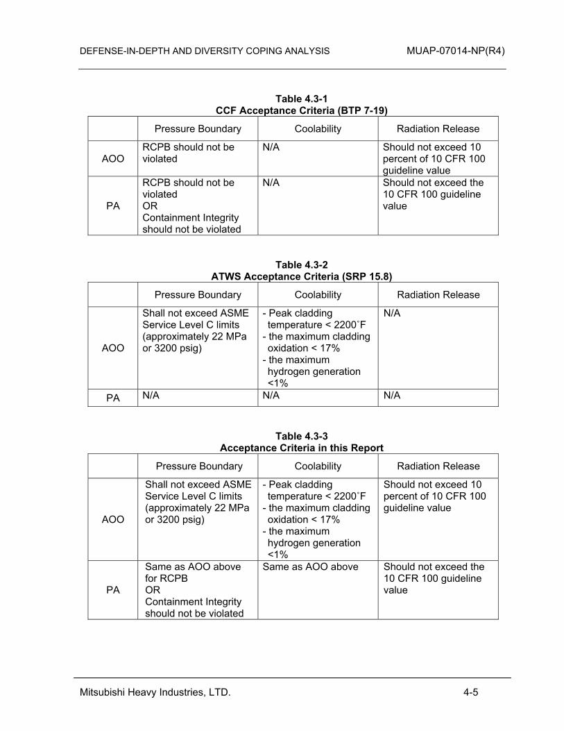
Table 4.3-1 summarizes the BTP 7-19 acceptance criteria. SRP 15.8 describes the following acceptance criteria for ATWS.
• The RCS pressure shall not exceed ASME Service Level C limits (approximately 22 MPa or 3200 psig)
• Peak cladding temperature shall not exceed 2200˚F. The maximum cladding oxidation shall not exceed 17% of the total cladding thickness before oxidation. The maximum hydrogen generation shall not exceed 1% of the maximum hypothetical amount if all the fuel cladding had reacts to produce hydrogen.
Table 4.3-2 summarizes the ATWS acceptance criteria.
DEFENSE-IN-DEPTH AND DIVERSITY COPING ANALYSIS MUAP-07014-NP(R4)
Mitsubishi Heavy Industries, LTD. 4-4
Table 4.3-3 summarizes the acceptance criteria utilized in this report. For the integrity of the RCS pressure boundary, the ATWS criterion is applied in this report. The RCS pressure boundary integrity can be considered to be maintained if the ATWS criterion is met. The ATWS criterion for coolability is not necessary to apply for the D3 coping analysis. The SRP criteria are for pressure boundary and dose. Dose evaluations are not necessary if core coolability is maintained. Therefore, this technical report conservatively adds the core coolability criteria to most events.
DEFENSE-IN-DEPTH AND DIVERSITY COPING ANALYSIS MUAP-07014-NP(R4)
Mitsubishi Heavy Industries, LTD. 4-5
Table 4.3-1 CCF Acceptance Criteria (BTP 7-19)
Pressure Boundary Coolability Radiation Release
AOO RCPB should not be violated
N/A Should not exceed 10 percent of 10 CFR 100 guideline value
PA
RCPB should not be violated OR Containment Integrity should not be violated
N/A Should not exceed the 10 CFR 100 guideline value
Table 4.3-2 ATWS Acceptance Criteria (SRP 15.8)
Pressure Boundary Coolability Radiation Release
AOO
Shall not exceed ASME Service Level C limits (approximately 22 MPa or 3200 psig)
- Peak cladding temperature < 2200˚F
- the maximum cladding oxidation < 17%
- the maximum hydrogen generation <1%
N/A
PA N/A N/A N/A
Table 4.3-3 Acceptance Criteria in this Report
Pressure Boundary Coolability Radiation Release
AOO
Shall not exceed ASME Service Level C limits (approximately 22 MPa or 3200 psig)
- Peak cladding temperature < 2200˚F
- the maximum cladding oxidation < 17%
- the maximum hydrogen generation <1%
Should not exceed 10 percent of 10 CFR 100 guideline value
PA
Same as AOO above for RCPB OR Containment Integrity should not be violated
Same as AOO above Should not exceed the 10 CFR 100 guideline value

DEFENSE-IN-DEPTH AND DIVERSITY COPING ANALYSIS MUAP-07014-NP(R4)
Mitsubishi Heavy Industries, LTD. 4-6
4.4 Diverse Actuation System Assumed in the D3 Coping Analysis
The DAS provides monitoring of key safety parameters and back-up automatic / manual actuation of the safety and non-safety components required to mitigate anticipated operational occurrences and accidents. The functions of the DAS provided to actuate the reactor trip, turbine trip, and main feedwater regulation valve closure, as well as to achieve secondary system core heat removal are described in Section 3.3. Table 4.4-1 summarizes the diverse reactor trip and diverse emergency feedwater actuation analytical limits and signal delay times (including the DAS timer delay) for functions used in the D3 coping analysis.
Table 4.4-1 DAS Actuation Analytical Limit and Time Delays
Assumed for D3 Coping Analysis
Actuation Signal Analytical Limit Time Delay (sec)
1. Diverse reactor trip
High pressurizer pressure 2440 psia 10
Low pressurizer pressure 1840 psia 10
Low steam generator water level 7% of span 10
2. Diverse emergency feedwater actuation
Low steam generator water level 7% of span 10.0 (Turbine-driven)153.0 (Motor-driven)*1
3. Diverse ECCS actuation
Low-Low pressurizer pressure 1740 psia 123.0 *1 The motor-driven EFW pump timer delay is designed to avoid a spurious DAS actuation during
a loss of offsite power when there is no digital CCF.
DEFENSE-IN-DEPTH AND DIVERSITY COPING ANALYSIS MUAP-07014-NP(R4)
Mitsubishi Heavy Industries, LTD. 4-7
4.5 Evaluation Models
The computer codes used for the D3 coping analysis are the same as those used in the analyses provided in Chapter 15 of the DCD. The best-estimate assumptions that differ from the Chapter 15 analyses are modeled by changing code inputs, not by changes to the codes. For completeness, summaries of the key capabilities of the MARVEL-M and VIPRE-01M codes are provided here, excerpted from the US-APWR DCD and MUAP-07010 (Reference 5). MARVEL-M (Reference 5) is a multi-loop plant system transient analysis code used to calculate detailed transient behavior of pressurized water reactor (PWR) systems. MARVEL-M has a maximum modeling capability of four coolant loops with four steam generators and associated systems. It simulates reactor kinetics, thermal-hydraulics of the core and RCS, the pressurizer, main and secondary steam and feedwater systems, and the reactor control and protection system. It also simulates the engineered safety features (ESFs) systems and other subsystems, which are representative of conventional PWR power plants. The MARVEL-M program utilizes a space-independent single point reactor kinetics model with six delayed neutron groups. The thermal and hydraulic characteristics of the RCS are described by time- and space-dependent differential equations. The RCS is represented by flow nodes, which model transient behaviors of mass and energy for the ranges of sub-cooled and homogenous two phase fluid typically encountered in the analysis of non-LOCA transients. Pressurizer heaters, spray, and safety valves are also considered in the program. Reactivity effects from the moderator, fuel, boron, and rods are also included. MARVEL-M also simulates the protection and monitoring system and control systems. MARVEL-M has the ability to calculate the value of departure from nucleate boiling ratio (DNBR) during a transient using a simple calculation model. The model employs user-input values of the DNBR at nominal core conditions and selected DNBR limits represented by operating parameters of core inlet temperature, pressure and power levels. The simplified DNBR model closely agrees with design calculations when the core operating conditions do not exceed the design flux distribution or core protection limits. When conditions exceed these limitations, DNBR analysis is performed by the more detailed external calculation code, VIPRE-01M. MARVEL-M outputs the transient response of reactor power, reactor pressure, primary coolant temperature, DNBR, and other parameters. Inputs into the code include initial conditions such as primary coolant temperature and the reactor power, primary coolant volume and other plant data, nuclear characteristics data, and setpoints for actuation of the reactor trip system and ESF systems. The program is applicable to both conventional as well as advanced PWR plants. VIPRE-01M (Reference 6) is a subchannel thermal hydraulic analysis code with both steady state and transient capabilities, including a fuel thermal transient model. It divides the core into three-dimensional mesh elements and then solves the appropriate equations by applying the mass, momentum, and energy conservation principles to each mesh element. Inputs into VIPRE-01M include initial conditions such as reactor power, coolant
DEFENSE-IN-DEPTH AND DIVERSITY COPING ANALYSIS MUAP-07014-NP(R4)
Mitsubishi Heavy Industries, LTD. 4-8
temperature, coolant flow, power distributions, core geometry and fuel properties. VIPRE-01M calculates time-dependent changes in parameters, such as coolant temperature, coolant density, void fraction, fuel temperature, and minimum DNBR in the core. Boundary conditions include transient data generated by other codes such as MARVEL-M. The WCOBRA/TRAC (M1.0) code, a modified version of the WCOBRA/TRAC code, is used for calculation of thermal-hydraulic behavior during a large break LOCA. It’s applicability to the US-APWR large break LOCA analysis is discussed in the Topical Report (Reference 13). WCOBRA/TRAC is approved by the U.S. Nuclear Regulatory Commission for use in best estimate large break LOCA calculations for three and four loop conventional PWRs, also the AP600 and AP1000 advanced plant designs. The COBRA portion of the code is based on a two-fluid, three-field, multi-dimensional fluid equations to describe thermal-hydraulic behavior of the vessel component. The TRAC portion of the code is based on one-dimensional, two-phase drift flux model to describe thermal-hydraulic behavior of the major components of PWR, such as steam generators, pipes, pumps, valves and pressurizer. 4.6 Event Evaluation Methods
As described in Section 4.2, the D3 coping analysis evaluation is performed for each event that is evaluated in the DCD Chapter 15 accident analysis. Each event is evaluated based on one of the three following method described in MUAP-07006:
• Equivalent protection • Expertly judged • Analyzed
There are a number of DCD Chapter 15 events that do not result in a reactor trip by the reactor trip system (RTS) or ESF mitigating action and that have been shown to meet the AOO acceptance criteria in the conservative DCD analysis. These events are classified in the coping analysis as “equivalent protection”. If these events were reanalyzed with an assumed common cause failure of the reactor trip and ESF actuation, a their response would be identical to the DCD because no trips or ESF signals are assumed in the DCD Chapter 15 analysis, and the PCMS is assumed to fail in the worst case condition. The DCD worst case failure consideration for the PCMS encompasses the two CCF conditions defined for the PCMS in section 3.2.3. An example of such an event is the increase in main steam flow event. There are three normal automatic reactor trip functions that are duplicated by the DAS (high pressurizer pressure, low pressurizer pressure, and low steam generator water level). For events in DCD Chapter 15 that credit these specific reactor trips, if a CCF disabled the normal automatic reactor trip or ESF actuation functions, an automatic DAS trip would occur on the same trip function. The loss of normal feedwater flow event is an example of such an event (normally trips and initiates emergency feedwater system (EFWS) on low steam generator water level). However, the DAS trip setpoints are less conservative than the RTS/ESF setpoints and they are delayed by 10 seconds. Similar

DEFENSE-IN-DEPTH AND DIVERSITY COPING ANALYSIS MUAP-07014-NP(R4)
Mitsubishi Heavy Industries, LTD. 4-9
to the “equivalent protection” event group, for most events in the “expertly judged” category there is no transient analysis performed for the D3 coping analysis. Instead, the additional effect of setpoint / delay is “expertly judged” to have minimal impact on the event scenario. Therefore, most events in this category are considered to be in the “expertly judged” group defined by MUAP-07006. If the effect of the setpoint / delay cannot be “expertly judged” to have minimal impact, the event is “analyzed”. There are groups of events that, when analyzed without automatic reactor trips, will approach the same or similar condition; if one of these events is analyzed and found to meet the acceptance limit, all of them will meet the same limit. The reactor coolant pump (RCP) locked rotor, RCP sheared shaft events and partial loss of forced reactor coolant flow are examples of this. The limiting core condition for these events in the absence of an automatic reactor trip occurs at the same or similar condition after the reactor coolant pump comes to a complete stop. In such cases, the D3 coping analysis technical report provides a transient analysis for one of the events (assigns it to “analyzed” group) and assigns the other similar events to the “expertly judged” group.
DEFENSE-IN-DEPTH AND DIVERSITY COPING ANALYSIS MUAP-07014-NP(R4)
Mitsubishi Heavy Industries, LTD. 5-1
5.0 D3 COPING ANALYSIS RESULTS
The results of each event are evaluated according to the following criteria as described in Table 4.3-3:
• Pressure boundary integrity o Reactor Coolant Pressure Boundary (RCPB) o Containment Vessel (C/V)
• Core coolability • Dose
Additional background on the analysis approach and event screening common to all events for each of the criteria is provided below. (1) Pressure boundary integrity
For RCPB integrity, the capacity of the pressurizer safety valve is designed so that this valve is able to release the maximum surge flow to the pressurizer assuming a turbine trip without a reactor trip, as long as the steam generator secondary side has sufficient water inventory. The DAS includes reactor trips and EFW actuation from the low steam generator water level signal. The reactor trips and EFW actuate from this signal before steam generator dry-out for events assuming a concurrent CCF. Therefore, the RCS pressure increase is mitigated by the DAS and the pressurizer safety valve which is not affected by CCF. Therefore, all DCD Chapter 15 safety analysis events assuming CCF are “expertly judged” events for the RCPB criterion. Section 5.2.1 provides a representative D3 coping analysis for the loss of load event to assure that the RCS pressure increase can be successfully mitigated by the pressurizer safety valve and the DAS. The C/V integrity for initiating events which breach the RCPB is described in each applicable event section. (2) Core coolability
For most events, core coolability is demonstrated by evaluating departure from nucleate boiling (DNB). Each event subsection describes the evaluation of core coolability. (3) Dose
Dose evaluations are not necessary if core coolability is maintained except for the events which lead to release of primary coolant from RCS outside the C/V. For most events concurrent with CCF, core coolability is maintained and an analysis is not performed. 5.1 Increase in Heat Removal by the Secondary System
5.1.1 Decrease in Feedwater Temperature as a Result of Feedwater System Malfunctions
A decrease in feedwater temperature causes a reduction in steam generator secondary temperature, resulting in an increase in primary-to-secondary heat transfer. In the presence of a negative moderator temperature coefficient (positive moderator density

DEFENSE-IN-DEPTH AND DIVERSITY COPING ANALYSIS MUAP-07014-NP(R4)
Mitsubishi Heavy Industries, LTD. 5-2
coefficient), the decrease in primary temperature (and associated increase in density) results in a positive reactivity insertion and core power increase. (1) Pressure Boundary Integrity
DCD Section 15.1.1 shows that the RCS pressure is not a significant adverse consequence without RTS/ESF actuation. Therefore, the integrity of the RCPB is maintained for this event concurrent with a CCF. (2) Core Coolability
DCD Section 15.1.1 shows that DNB does not occur without RTS/ESF actuation. Therefore, the core coolability is maintained for this event concurrent with a CCF. This event is categorized as an “equivalent protection” event for core coolability. (3) Dose
The core coolability is maintained for this event concurrent with a CCF. Therefore, the dose associated with this event does not exceed 10% of the 10 CFR 100 dose guidelines for AOOs. 5.1.2 Increase in Feedwater Flow as a Result of Feedwater System Malfunctions
An increase in the feedwater flow rate to the secondary side of the steam generator will increase the heat transfer from the primary to the secondary side of the steam generator. This will cause a reduction in the reactor coolant temperature at the reactor vessel inlet. In the presence of a negative moderator temperature coefficient (positive moderator density coefficient), the decrease in primary temperature (and associated increase in density) results in a positive reactivity insertion and core power increase. (1) Pressure Boundary Integrity
DCD Section 15.1.2 shows that the RCS pressure limit is not challenged even if the high-high steam generator water level reactor trip is not assumed. Therefore, the integrity of the RCPB is maintained for this event concurrent with a CCF. (2) Core Coolability
DCD Section 15.1.2 shows that the reactor power is approximately constant and DNB does not occur even if the high-high steam generator water level reactor trip is not assumed. Therefore, the core coolability is maintained for this event concurrent with a CCF. This event is categorized as an “equivalent protection” event for core coolability.
DEFENSE-IN-DEPTH AND DIVERSITY COPING ANALYSIS MUAP-07014-NP(R4)
Mitsubishi Heavy Industries, LTD. 5-3
(3) Dose
The core coolability is maintained for this event concurrent with a CCF. Therefore, the dose associated with this event does not exceed 10% of the 10 CFR 100 dose guidelines for AOOs. 5.1.3 Increase in Steam Flow as a Result of Steam Pressure Regulator Malfunction
A rapid increase in steam flow can cause a temporary mismatch between the power produced by the reactor core and the power demanded by the steam generators. This situation can reduce the temperature of the coolant re-entering the reactor vessel, which, in turn, can lead to an increase in reactor power. (1) Pressure Boundary Integrity
DCD Section 15.1.3 shows that the plant reaches a new steady state condition without a reactor trip being reached or credited. The RCS pressure limit is not challenged even without RTS/ESF actuation. Therefore, the integrity of the RCPB is maintained for this event concurrent with a CCF. (2) Core Coolability
DCD Section 15.1.3 shows that DNB does not occur without RTS/ESF actuation. Therefore, the core coolability is maintained for this event concurrent with a CCF. This event is categorized as an “equivalent protection” event for core coolability. (3) Dose
The core coolability is maintained for this event concurrent with a CCF. Therefore, the dose associated with this event does not exceed 10% of the 10 CFR 100 dose guidelines for AOOs. 5.1.4 Inadvertent Opening of a Steam Generator Relief or Safety Valve
The inadvertent opening of a main steam relief valve, main steam depressurization valve, main steam safety valve, or turbine bypass valve can cause a rapid increase in steam flow and a depressurization of the secondary system. The steam release removes energy from the RCS, which causes a reduction in the reactor coolant temperature and pressure. In the presence of a negative moderator temperature coefficient (positive moderator density coefficient), the decrease in primary temperature (and associated increase in density) results in a positive reactivity insertion and core power increase.

DEFENSE-IN-DEPTH AND DIVERSITY COPING ANALYSIS MUAP-07014-NP(R4)
Mitsubishi Heavy Industries, LTD. 5-4
DCD Section 15.1.4 evaluates this event from hot standby conditions. The evaluation of this event from hot full power conditions is bounded by the DCD Section 15.1.3 event analysis. Therefore, this event is not separately evaluated in the D3 coping analysis. 5.1.5 Steam System Piping Failures Inside and Outside of Containment
The increase in steam generation rate caused by the postulated steam system piping failure removes heat from the RCS, which, in turn, lowers the temperature and pressure of the RCS. In the presence of a negative moderator temperature coefficient (positive moderator density coefficient), the decrease in primary temperature (and associated increase in density) results in a positive reactivity insertion and core power increase. (1) Pressure Boundary Integrity
The RCS pressure is not a significant adverse consequence without RTS/ESF actuation. Therefore, the integrity of the RCPB is maintained for this event concurrent with a CCF. (2) Core Coolability
Under hot full power conditions, the increased reactivity causes an increase in core power and the core power is balanced at a new equilibrium condition if the reactor trip setpoint for DAS is not reached. However, the axial power distribution is mitigated by moderator reactivity feedback, thus DNB is not a significant adverse consequence without RTS/ESF actuation. Therefore, the core coolability is maintained for this event concurrent with a CCF. This event is categorized as an “equivalent protection” event for core coolability. (3) Dose
The core coolability is maintained for this event concurrent with a CCF. Therefore, the dose associated with this event does not exceed 10% of the 10 CFR 100 dose guidelines for AOOs and the 10 CFR 100 dose guidelines for PAs. 5.2 Decrease in Heat Removal by the Secondary System
5.2.1 Loss of External Load
The loss of load event is modeled by assuming an instantaneous step load decrease in both steam flow and feedwater flow from their full value (100%) to zero at the beginning of the transient. This assumption bounds all credible loss of load scenarios in the event group, such as loss of external load, turbine trip, loss of condenser vacuum, closure of main steam isolation valve. This assumption is the same as the DCD Chapter 15 safety analysis.
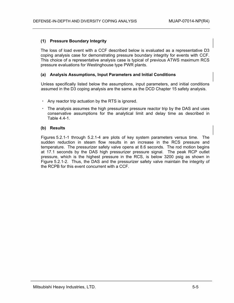
DEFENSE-IN-DEPTH AND DIVERSITY COPING ANALYSIS MUAP-07014-NP(R4)
Mitsubishi Heavy Industries, LTD. 5-5
(1) Pressure Boundary Integrity
The loss of load event with a CCF described below is evaluated as a representative D3 coping analysis case for demonstrating pressure boundary integrity for events with CCF. This choice of a representative analysis case is typical of previous ATWS maximum RCS pressure evaluations for Westinghouse type PWR plants. (a) Analysis Assumptions, Input Parameters and Initial Conditions
Unless specifically listed below the assumptions, input parameters, and initial conditions assumed in the D3 coping analysis are the same as the DCD Chapter 15 safety analysis.
・ Any reactor trip actuation by the RTS is ignored.
・ The analysis assumes the high pressurizer pressure reactor trip by the DAS and uses conservative assumptions for the analytical limit and delay time as described in Table 4.4-1.
(b) Results
Figures 5.2.1-1 through 5.2.1-4 are plots of key system parameters versus time. The sudden reduction in steam flow results in an increase in the RCS pressure and temperature. The pressurizer safety valve opens at 8.6 seconds. The rod motion begins at 17.1 seconds by the DAS high pressurizer pressure signal. The peak RCP outlet pressure, which is the highest pressure in the RCS, is below 3200 psig as shown in Figure 5.2.1-2. Thus, the DAS and the pressurizer safety valve maintain the integrity of the RCPB for this event concurrent with a CCF.
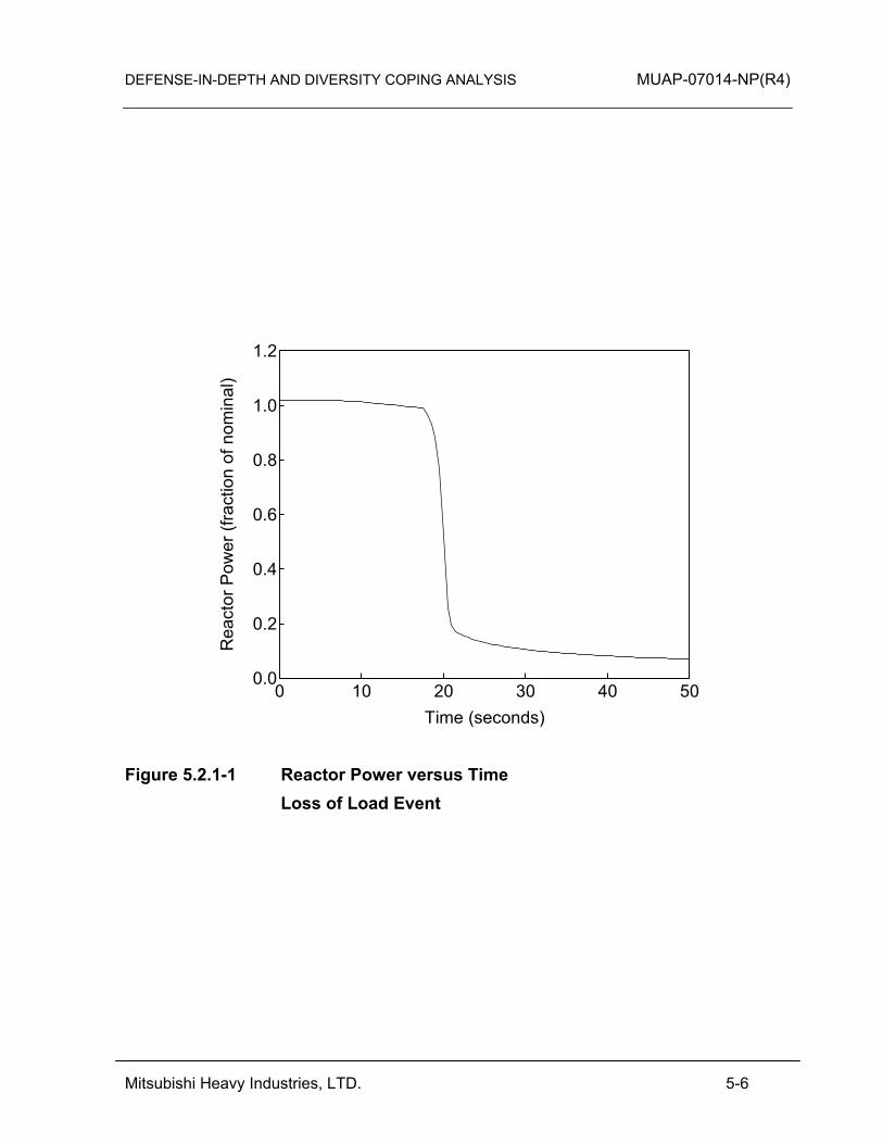
DEFENSE-IN-DEPTH AND DIVERSITY COPING ANALYSIS MUAP-07014-NP(R4)
Mitsubishi Heavy Industries, LTD. 5-6
1.2
1.0
0.8
0.6
0.4
0.2
0.0
Rea
ctor
Pow
er (f
ract
ion
of n
omin
al)
50403020100Time (seconds)
Figure 5.2.1-1 Reactor Power versus Time Loss of Load Event
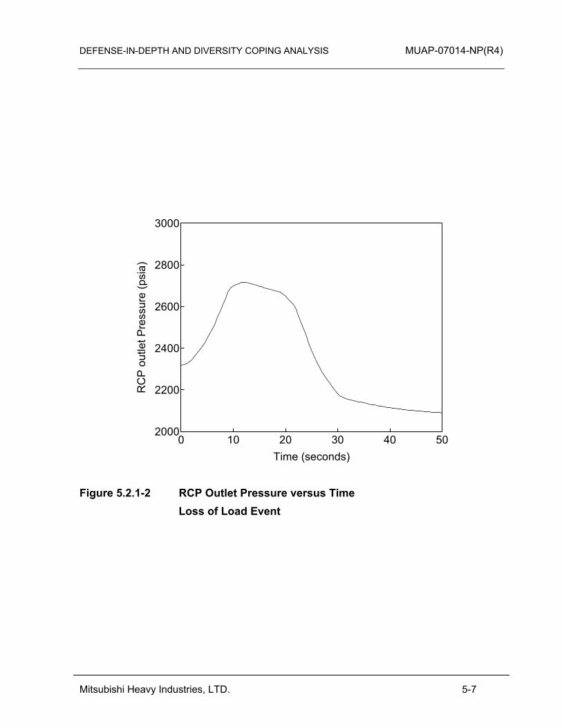
DEFENSE-IN-DEPTH AND DIVERSITY COPING ANALYSIS MUAP-07014-NP(R4)
Mitsubishi Heavy Industries, LTD. 5-7
3000
2800
2600
2400
2200
2000
RC
P o
utle
t Pre
ssur
e (p
sia)
50403020100Time (seconds)
Figure 5.2.1-2 RCP Outlet Pressure versus Time Loss of Load Event
DEFENSE-IN-DEPTH AND DIVERSITY COPING ANALYSIS MUAP-07014-NP(R4)
Mitsubishi Heavy Industries, LTD. 5-8
500
400
300
200
100
0Pre
ssur
izer
Saf
ety
Val
ve F
low
Rat
e (lb
/sec
)
50403020100Time (seconds)
Figure 5.2.1-3 Pressurizer Safety Valve Flow Rate versus Time Loss of Load Event
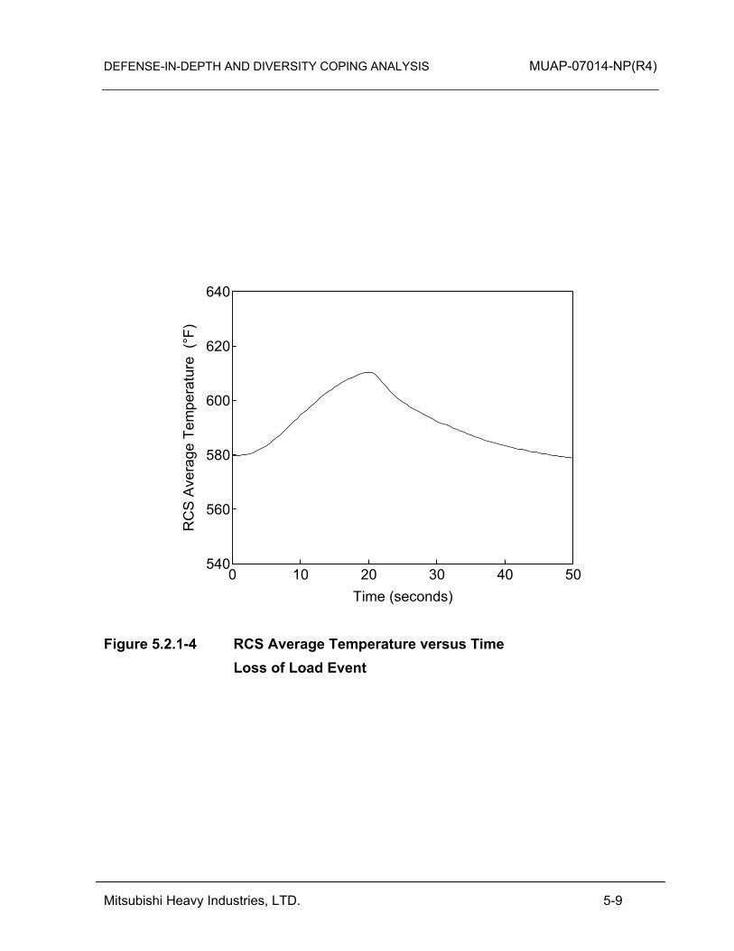
DEFENSE-IN-DEPTH AND DIVERSITY COPING ANALYSIS MUAP-07014-NP(R4)
Mitsubishi Heavy Industries, LTD. 5-9
640
620
600
580
560
540
RC
S A
vera
ge T
empe
ratu
re (
°F)
50403020100Time (seconds)
Figure 5.2.1-4 RCS Average Temperature versus Time Loss of Load Event
DEFENSE-IN-DEPTH AND DIVERSITY COPING ANALYSIS MUAP-07014-NP(R4)
Mitsubishi Heavy Industries, LTD. 5-10
(2) Core Coolability DCD Figure 15.2.1-1 shows that DNB does not occur by the time the high pressurizer pressure reactor trip occurs. DCD Table 15.2.1-1 shows the analytical limit is reached at 6.7 seconds from the event occurrence and rod motion begins at 8.5 seconds. The high pressurizer pressure analytical limit for the DCD and D3 analyses is 2425 psia and 2440 psia, respectively. For this event concurrent with a CCF, the analytical limit is expected to be reached at almost the same time because the difference of the limits is quite small and the rate of pressure increase is high. The DAS delay time of 10 seconds is greater than that of the RTS. For this event concurrent with a CCF, the rod motion is expected to begin prior to 20 seconds. If the DNBR shown in DCD Figure 15.2.1-1 is extrapolated at the slope prior to trip, the DNBR will remain above the 95/95 limit at 20 seconds. Also, this evaluation is based on the conservative assumptions of DCD Section 15.2.1 for the axial power distribution and moderator temperature coefficient. Therefore, DNB does not occur and, the core coolability is maintained for this event concurrent with a CCF. This event is categorized as an “expertly judged” event for core coolability. (3) Dose The core coolability is maintained for this event concurrent with a CCF. Therefore, the dose associated with this event does not exceed 10% of the 10 CFR 100 dose guidelines for AOOs. 5.2.2 Turbine Trip
This event is same as Section 5.2.1 in this report. 5.2.3 Loss of Condenser Vacuum
This event is same as Section 5.2.1 in this report. 5.2.4 Closure of Main Steam Isolation Valve
This event is same as Section 5.2.1 in this report. 5.2.5 Steam Pressure Regulator Failure
There are no steam pressure regulators in the US-APWR whose malfunction or failure could result in a steam flow transient. 5.2.6 Loss of Non-Emergency AC Power to the Station Auxiliaries
The loss of non-emergency alternating current (ac) power is assumed to result in the loss of all power to the station auxiliaries. The causes are a complete loss of the external
DEFENSE-IN-DEPTH AND DIVERSITY COPING ANALYSIS MUAP-07014-NP(R4)
Mitsubishi Heavy Industries, LTD. 5-11
(offsite) grid accompanied by a turbine-generator trip or loss of the onsite ac distribution system. (1) Pressure Boundary Integrity
The RCS pressure increase is mitigated by the pressurizer safety valve and the DAS high pressurizer pressure reactor trip actuation. Therefore, the integrity of the RCPB is maintained for this event concurrent with a CCF. (2) Core Coolability
The loss of non-emergency AC power causes the loss of power supply for the motor generator (M/G) set and results in the rod cluster control assembly (RCCA) trip, which does not cause a DNBR violation. Therefore, the core coolability is maintained for this event concurrent with a CCF. This event is categorized as an “equivalent protection” event for core coolability. (3) Dose
The core coolability is maintained for this event concurrent with a CCF. Therefore, the dose associated with this event does not exceed 10% of the 10 CFR 100 dose guidelines for AOOs. 5.2.7 Loss of Normal Feedwater Flow
A loss of normal feedwater flow could occur from pump failures, valve malfunctions, or a loss of offsite power. The loss of feedwater flow results in a reduction of the secondary system’s ability to remove heat generated by the reactor core. As a result, the reactor coolant temperature and pressure increase and will eventually require a reactor trip to protect the fuel and reactor coolant pressure boundary. (1) Pressure Boundary Integrity
The RCS pressure increase is mitigated by the pressurizer safety valve and the DAS trip and initiation of the Emergency Feedwater System. Therefore, the integrity of the RCPB is maintained for this event concurrent with a CCF. (2) Core Coolability
DCD Figure 15.2.7-1 shows that DNB does not occur by the low steam generator water level reactor trip. The analytical limit for the DCD analysis is 0% of narrow range level span which is lower than the DAS actuation analytical limit (7%). Figure 15.2.7-1 shows that DNBR begins to recover by the reactor trip after about 70 seconds. For this event concurrent with a CCF, the DAS delay time of 10 seconds is greater than that of the RTS.
DEFENSE-IN-DEPTH AND DIVERSITY COPING ANALYSIS MUAP-07014-NP(R4)
Mitsubishi Heavy Industries, LTD. 5-12
Thus, rod motion is expected to begin at 80 seconds. If the DNBR shown in DCD Figure 15.2.7-1 is extrapolated at the slope prior to the trip, the DNBR will remain above the 95/95 limit at 80 seconds. Also, this evaluation is based on the conservative assumptions of DCD Section 15.2.7 for the axial power distribution and moderator temperature coefficient. Therefore, DNB does not occur and, the core coolability is maintained for this event concurrent with a CCF. This event is categorized as an “expertly judged” event for core coolability. (3) Dose
The core coolability is maintained for this event concurrent with a CCF. Therefore, the dose associated with this event does not exceed 10% of the 10 CFR 100 dose guidelines for AOOs. 5.2.8 Feedwater System Pipe Break Inside and Outside Containment
The feedwater system pipe break is a non-uniform transient that involves modeling the flow from one of the secondary loops. Unlike the secondary piping rupture resulting in RCS cool down analyzed in DCD Section 15.1.5, the feedwater system pipe break analyzed in DCD Section 15.2.8 causes a loss of inventory from the saturated liquid mass in the steam generator resulting in RCS heat-up and pressurization. Unless the heat-up of the RCS is mitigated, there will be a possibility of water relief through the pressurizer safety valve. (1) Pressure Boundary Integrity
The RCS pressure increase is mitigated by the pressurizer safety valve and the DAS low steam generator water level reactor trip actuation and initiation of the Emergency Feedwater System. Therefore, the integrity of the RCPB is maintained for this event concurrent with a CCF. (2) Core Coolability
This event in the DCD is bounded by the minimum DNBR for the DCD Section 15.2.7 event in that DNB does not occur by the low steam generator water level reactor trip. Although the diverse low steam generator water level reactor trip analytical limit is lower and the delay time is greater than that of the RTS, DNB is not a significant adverse consequence considering the axial power distribution for the BOC. On the other hand, DNB is mitigated by the effect of the RCS cool down because of the discharge of two-phase flow from the feedwater line after the perforated nozzle is uncovered by the secondary water in this event. Therefore, the core coolability is maintained for this event concurrent with a CCF. This event is categorized as an “expertly judged” event for core coolability. (3) Dose
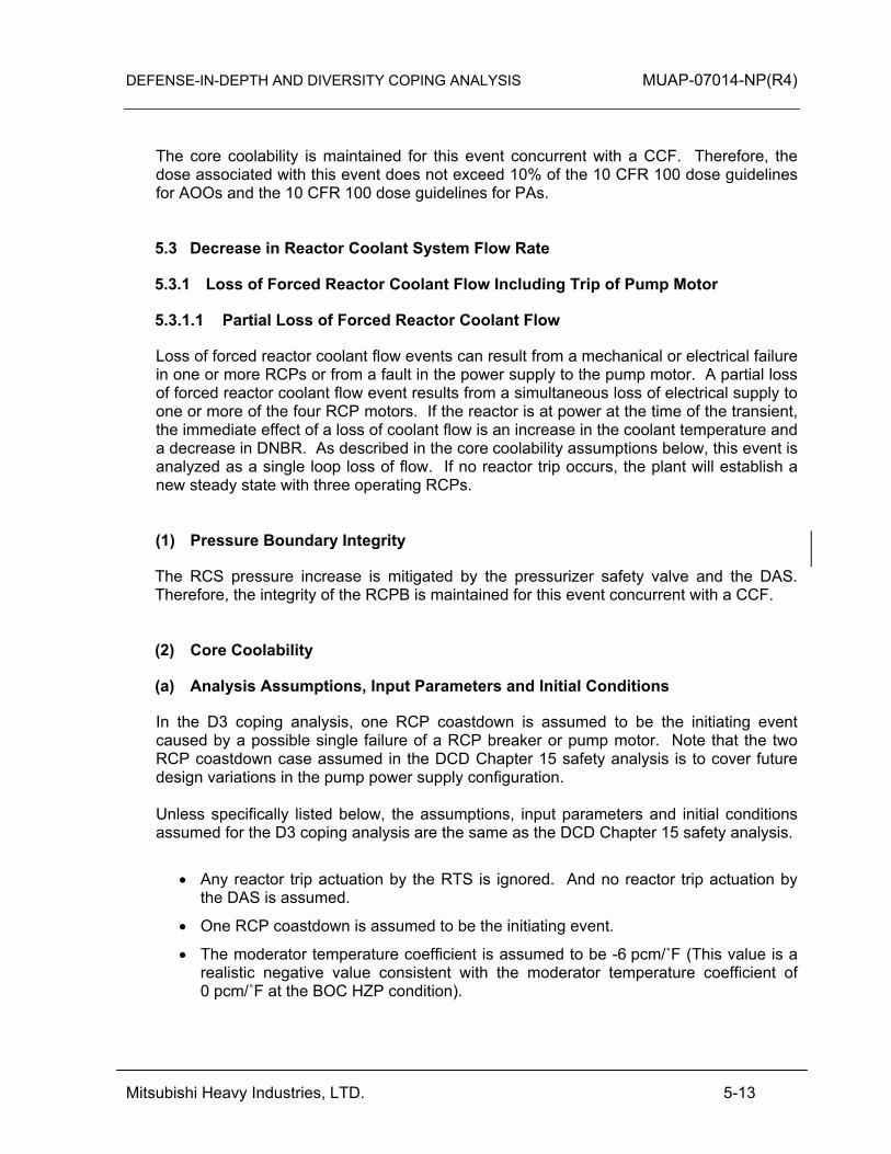
DEFENSE-IN-DEPTH AND DIVERSITY COPING ANALYSIS MUAP-07014-NP(R4)
Mitsubishi Heavy Industries, LTD. 5-13
The core coolability is maintained for this event concurrent with a CCF. Therefore, the dose associated with this event does not exceed 10% of the 10 CFR 100 dose guidelines for AOOs and the 10 CFR 100 dose guidelines for PAs. 5.3 Decrease in Reactor Coolant System Flow Rate
5.3.1 Loss of Forced Reactor Coolant Flow Including Trip of Pump Motor
5.3.1.1 Partial Loss of Forced Reactor Coolant Flow
Loss of forced reactor coolant flow events can result from a mechanical or electrical failure in one or more RCPs or from a fault in the power supply to the pump motor. A partial loss of forced reactor coolant flow event results from a simultaneous loss of electrical supply to one or more of the four RCP motors. If the reactor is at power at the time of the transient, the immediate effect of a loss of coolant flow is an increase in the coolant temperature and a decrease in DNBR. As described in the core coolability assumptions below, this event is analyzed as a single loop loss of flow. If no reactor trip occurs, the plant will establish a new steady state with three operating RCPs. (1) Pressure Boundary Integrity
The RCS pressure increase is mitigated by the pressurizer safety valve and the DAS. Therefore, the integrity of the RCPB is maintained for this event concurrent with a CCF. (2) Core Coolability
(a) Analysis Assumptions, Input Parameters and Initial Conditions
In the D3 coping analysis, one RCP coastdown is assumed to be the initiating event caused by a possible single failure of a RCP breaker or pump motor. Note that the two RCP coastdown case assumed in the DCD Chapter 15 safety analysis is to cover future design variations in the pump power supply configuration. Unless specifically listed below, the assumptions, input parameters and initial conditions assumed for the D3 coping analysis are the same as the DCD Chapter 15 safety analysis.
• Any reactor trip actuation by the RTS is ignored. And no reactor trip actuation by the DAS is assumed.
• One RCP coastdown is assumed to be the initiating event.
• The moderator temperature coefficient is assumed to be -6 pcm/˚F (This value is a realistic negative value consistent with the moderator temperature coefficient of 0 pcm/˚F at the BOC HZP condition).

DEFENSE-IN-DEPTH AND DIVERSITY COPING ANALYSIS MUAP-07014-NP(R4)
Mitsubishi Heavy Industries, LTD. 5-14
• The Doppler power coefficient is assumed considering 20% margin on the core design value. This margin is smaller than the margin used in the DCD Chapter 15 safety analysis, but still a conservative value.
• Although the DNBR analysis in VIPRE-01M can use the transient values of RCS pressure and core inlet temperature calculated by MARVEL-M, the pressure and core inlet temperature are conservatively assumed to be constant (the same as in the DCD Chapter 15 safety analysis).
The power distribution is assumed to be the limiting design power distribution used in the DCD Chapter 15 safety analysis. Although the axial power distribution for the BOC case could be mitigated by assuming the power shape consistent with the core burn-up, this mitigating assumption is not made in these analyses. (b) Results
Figures 5.3.1.1-1 through 5.3.1.1-5 are plots of key system parameters versus time. The reduction of the core flow causes an increase of RCS average temperature. The reactor power is reduced by the moderator reactivity feedback. The minimum DNBR is above the 95/95 DNBR limit. Therefore, the core coolability criterion is met. The peak cladding temperature does not exceed 2200˚F and the core coolability is maintained for this event concurrent with a CCF. (3) Dose
The core coolability is maintained for this event concurrent with a CCF. Therefore, the dose associated with this event does not exceed 10% of the 10 CFR 100 dose guidelines for AOOs.
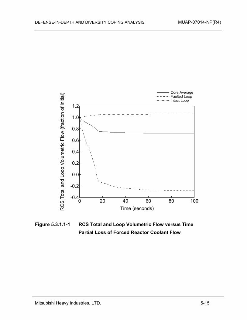
DEFENSE-IN-DEPTH AND DIVERSITY COPING ANALYSIS MUAP-07014-NP(R4)
Mitsubishi Heavy Industries, LTD. 5-15
1.2
1.0
0.8
0.6
0.4
0.2
0.0
-0.2
-0.4
RC
S T
otal
and
Loo
p V
olum
etric
Flo
w (f
ract
ion
of in
itial
)
100806040200Time (seconds)
Core Average Faulted Loop Intact Loop
Figure 5.3.1.1-1 RCS Total and Loop Volumetric Flow versus Time Partial Loss of Forced Reactor Coolant Flow
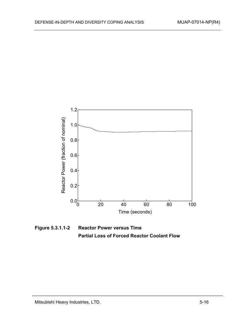
DEFENSE-IN-DEPTH AND DIVERSITY COPING ANALYSIS MUAP-07014-NP(R4)
Mitsubishi Heavy Industries, LTD. 5-16
1.2
1.0
0.8
0.6
0.4
0.2
0.0
Rea
ctor
Pow
er (f
ract
ion
of n
omin
al)
100806040200Time (seconds)
Figure 5.3.1.1-2 Reactor Power versus Time Partial Loss of Forced Reactor Coolant Flow
DEFENSE-IN-DEPTH AND DIVERSITY COPING ANALYSIS MUAP-07014-NP(R4)
Mitsubishi Heavy Industries, LTD. 5-17
3000
2800
2600
2400
2200
2000
RC
S P
ress
ure
(psi
a)
100806040200Time (seconds)
Figure 5.3.1.1-3 RCS Pressure versus Time Partial Loss of Forced Reactor Coolant Flow
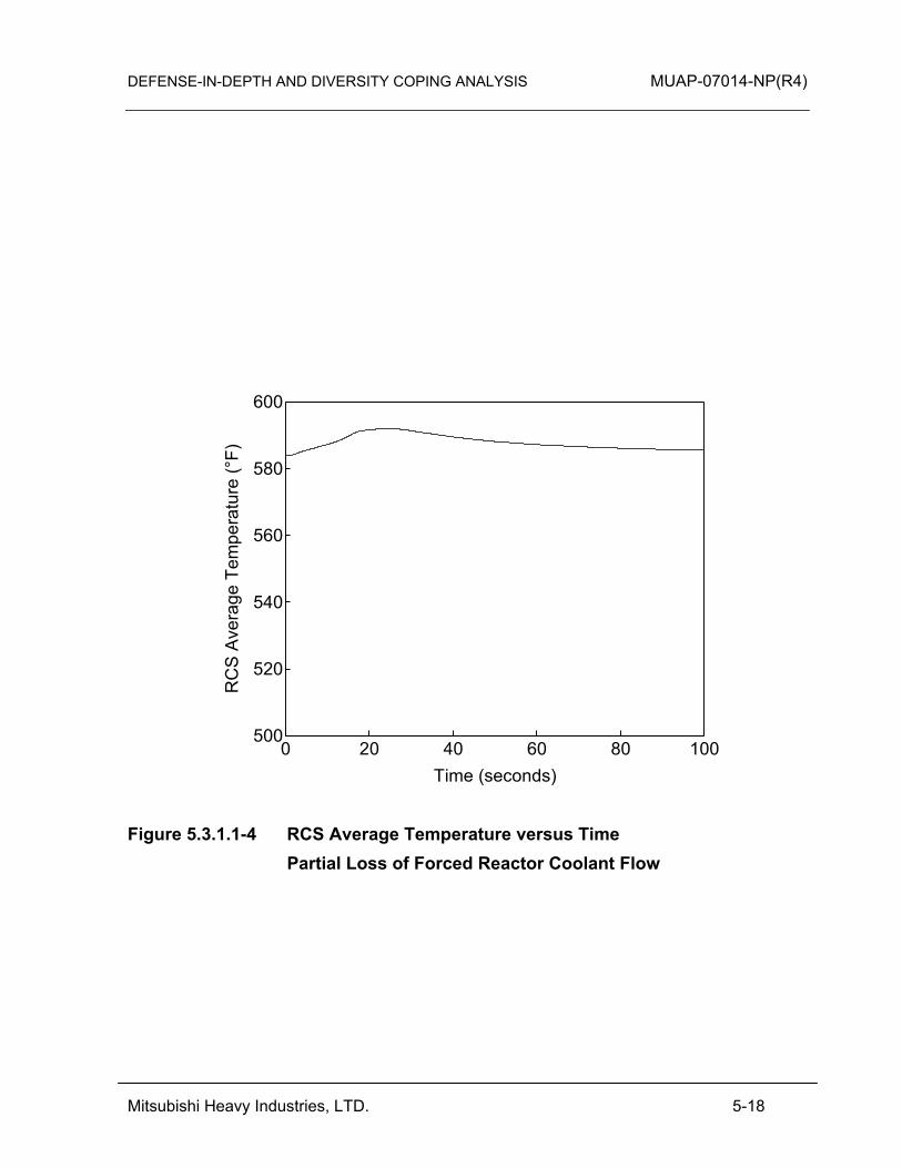
DEFENSE-IN-DEPTH AND DIVERSITY COPING ANALYSIS MUAP-07014-NP(R4)
Mitsubishi Heavy Industries, LTD. 5-18
600
580
560
540
520
500
RC
S A
vera
ge T
empe
ratu
re (°
F)
100806040200Time (seconds)
Figure 5.3.1.1-4 RCS Average Temperature versus Time Partial Loss of Forced Reactor Coolant Flow
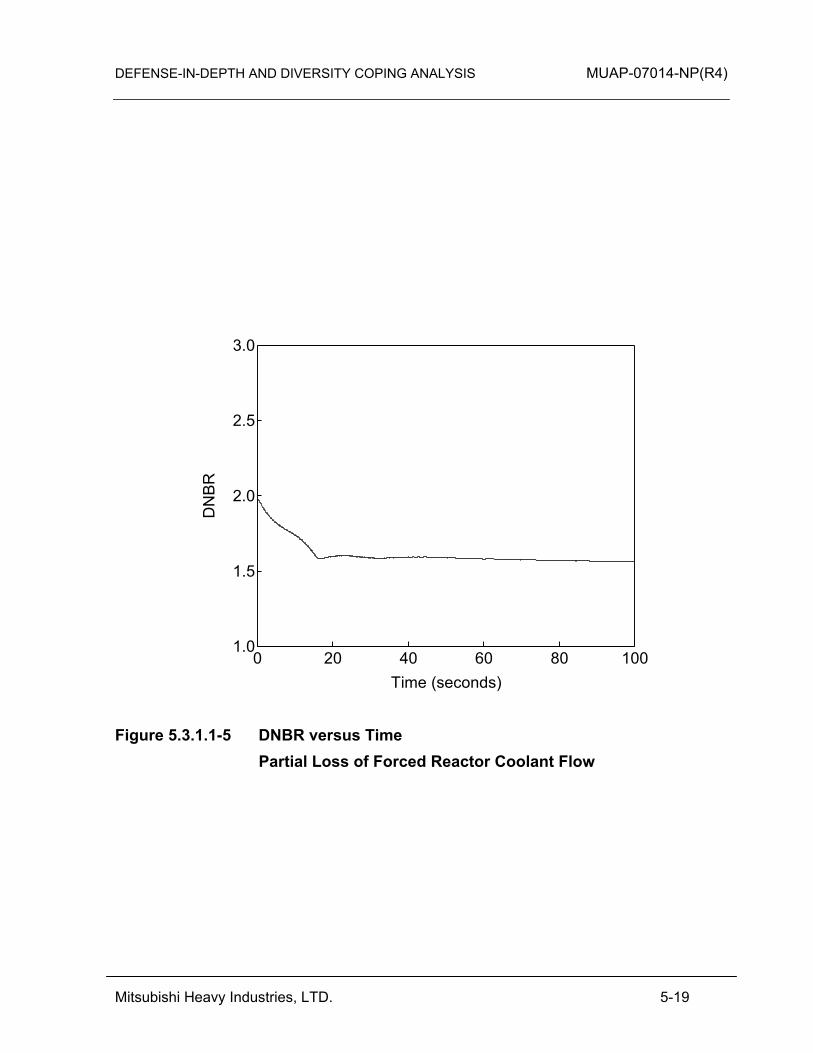
DEFENSE-IN-DEPTH AND DIVERSITY COPING ANALYSIS MUAP-07014-NP(R4)
Mitsubishi Heavy Industries, LTD. 5-19
3.0
2.5
2.0
1.5
1.0
DN
BR
100806040200Time (seconds)
Figure 5.3.1.1-5 DNBR versus Time Partial Loss of Forced Reactor Coolant Flow
DEFENSE-IN-DEPTH AND DIVERSITY COPING ANALYSIS MUAP-07014-NP(R4)
Mitsubishi Heavy Industries, LTD. 5-20
5.3.1.2 Complete Loss of Forced Reactor Coolant Flow
The complete loss of forced reactor coolant flow is initiated by malfunctions that cause the loss of electrical power or the decrease of offsite power frequency to all four reactor coolant pumps during power operation, resulting in a reduction in the core cooling capability. If the reactor is at power at the time of the transient, the immediate effect of a complete loss of coolant flow is a rapid increase in coolant temperature and decrease in minimum DNBR. Because the RCPs are fed by more than one bus, the only credible way for a complete loss of forced reactor coolant flow to occur is from a loss of offsite power that also affects the reactor protection M/G sets. (1) Pressure Boundary Integrity
The RCS pressure increase is mitigated by the pressurizer safety valve and the DAS high pressurizer pressure reactor trip actuation. Therefore, the integrity of the RCPB is maintained for this event concurrent with a CCF. (2) Core Coolability
The loss of non-emergency AC power causes the loss of power supply for the M/G set and results in the RCCA trip, which does not cause a DNBR violation. Therefore, the core coolability is maintained for this event concurrent with a CCF. This event is categorized as an “equivalent protection” event for core coolability. (3) Dose
The core coolability is maintained for this event concurrent with a CCF. Therefore, the dose associated with this event does not exceed 10% of the 10 CFR 100 dose guidelines for AOOs. 5.3.2 Flow Controller Malfunctions
This section is not applicable to the US-APWR because it does not have reactor coolant system flow controllers. 5.3.3 Reactor Coolant Pump Rotor Seizure
This event is initiated by the instantaneous seizure of one RCP rotor during power operation. This postulated rotor seizure would cause a rapid reduction in the reactor coolant flow (compared to the coastdown associated with an RCP trip) resulting in a decrease in core cooling capacity. This could, in turn, lead to an increase in the reactor fuel temperature, primary coolant temperature, and reactor pressure. This event is sometimes referred to as a locked pump rotor transient.

DEFENSE-IN-DEPTH AND DIVERSITY COPING ANALYSIS MUAP-07014-NP(R4)
Mitsubishi Heavy Industries, LTD. 5-21
A limiting case is defined for the locked rotor accident that also bounds the plant response to the RCP shaft break event discussed in DCD Section 15.3.4. The bounding case in DCD Section 15.3.3 is defined by assuming the RCP rotor is stopped prior to flow reversal, and that the pump resistance is changed to zero after the flow reverses in the affected loop. The evaluation of this event concurrent with a CCF assumes the same case as DCD Section 15.3.3. (1) Pressure Boundary Integrity
The RCS pressure increase is mitigated by the pressurizer safety valve and the DAS high pressurizer pressure reactor trip actuation and EFWS actuation. Therefore, the integrity of the RCPB is maintained for this event concurrent with a CCF. (2) Core Coolability
Similar to the partial loss of flow described in Section 5.3.1.1, this event concurrent with a CCF does not result in a DAS reactor trip. Although the reduction of the core flow rate of this event is slightly more severe than the Section 5.3.1.1 partial loss of flow event, both events reach a similar steady state equilibrium, although the flow rate for this event is slightly lower than the partial loss of flow event. Unlike the partial loss of flow event described above, the best estimate axial power distribution for the BOC condition is credited to demonstrate that DNB does not occur. Therefore, the core coolability is maintained for this event concurrent with a CCF. This event is categorized as an “expertly judged” event for core coolability. (3) Dose
This core coolability is maintained for this event concurrent with a CCF. Therefore, the dose associated with this event does not exceed the 10 CFR 100 dose guidelines for PAs. 5.3.4 Reactor Coolant Pump Shaft Break
A conservative bounding event concurrent with a CCF was considered for the reactor coolant pump rotor seizure that bounds the response and results for the reactor coolant pump shaft break as discussed above in Section 5.3.3. Therefore, this event concurrent with a CCF is bounded by the Section 5.3.3 results.

DEFENSE-IN-DEPTH AND DIVERSITY COPING ANALYSIS MUAP-07014-NP(R4)
Mitsubishi Heavy Industries, LTD. 5-22
5.4 Reactivity and Power Distribution Anomalies
5.4.1 Uncontrolled Control Rod Assembly Withdrawal from a Subcritical or Low Power Startup Condition
A RCCA withdrawal incident is an uncontrolled addition of reactivity to the reactor core caused by the withdrawal of RCCA banks, which results in a power increase. The occurrence of such a transient can be caused by a malfunction of the reactor control system or the control rod drive system. This incident could occur with the reactor in a subcritical state. In the D3 coping analysis, the plant is assumed to be operating in Mode 1 at rated power. This assumption covers the majority of the operational time interval of the plant which means this assumption covers the most likely plant conditions for events with a concurrent CCF. The percentage of time that the plant is in a subcritical condition is small compared to the time at power during the life of the plant. During periods of subcritical operation, the Doppler feedback effect stops the power excursion and the DAS high pressure trip terminates the event. The RCS pressure increase is mitigated by the pressurizer safety valve and the DAS high pressurizer pressure reactor trip and subsequent actuation of the EFWS. Therefore, the integrity of the RCPB is maintained for this event concurrent with a CCF. The dose associated with this event does not exceed 10% of the 10 CFR 100 dose guidelines for AOOs because the RCPB and the C/V integrity can be maintained. 5.4.2 Uncontrolled Control Rod Assembly Withdrawal at Power
The uncontrolled control rod assembly withdrawal at power is caused by a control system or rod control system failure that causes a bank withdrawal to occur. An uncontrolled control rod assembly withdrawal at power results in an increase in core heat flux. Since the heat extracted from the steam generator lags behind the core power until the steam generator pressure reaches the main steam safety valve setpoint, the reactor coolant temperature tends to increase. Without a manual or automatic reactor trip (typically the over temperature ΔT, high power range neutron flux, and high pressurizer pressure), the power mismatch and the rise of reactor coolant temperature could eventually result in DNB. (1) Pressure Boundary Integrity
The RCS pressure increase is mitigated by the pressurizer safety valve and the DAS. Therefore, the integrity of the RCPB is maintained for this event concurrent with a CCF.
DEFENSE-IN-DEPTH AND DIVERSITY COPING ANALYSIS MUAP-07014-NP(R4)
Mitsubishi Heavy Industries, LTD. 5-23
(2) Core Coolability
(a) Analysis Assumptions, Input Parameters and Initial Conditions
Unless specifically listed below the assumptions, input parameters and initial conditions assumed in the D3 coping analysis are the same as the DCD Chapter 15 safety analysis.
• Any reactor trip actuation by the RTS is ignored and no reactor trip actuation by the DAS is assumed.
• The reactivity inserted into the core is assumed to be 200 pcm for the BOC case and 500 pcm for the end-of-cycle (EOC) case consistent with the available reactivity of the RCCA bank-D withdrawal from the insertion limit to the all rods fully withdrawn position.
• The withdrawal of the RCCA is assumed to be at possible maximum speed. It takes 50 seconds to withdraw RCCA bank-D from the insertion limit to the all rods fully withdrawn position.
• The moderator temperature coefficient is assumed to be -6 pcm/˚F for the BOC case and -30 pcm/˚F for the EOC case (These values are realistic negative values consistent with the moderator temperature coefficient of 0 pcm/˚F at the BOC HZP condition).
• The Doppler power coefficient is assumed considering 20% margin on the core design value. This margin is smaller than the margin used in the DCD Chapter 15 safety analysis, but is still a conservative value.
The power distribution is assumed to be the limiting design power distribution used in the of the DCD Chapter 15 safety analysis. The axial power distribution for the BOC case may be mitigated by assuming the power shape consistent with the core burn-up, but is not adopted in this analysis. (b) Results
Figures 5.4.2-1 through 5.4.2-4 are plots of key system parameters versus time. The reactivity insertion results in increase in core heat flux, RCS temperature, and decrease in DNBR. However after the end of the reactivity insertion at 50 seconds due to a fully withdrawn control rod, the reactor power is reduced by the moderator reactivity feedback and the Doppler reactivity feedback. Figures 5.4.2-4 shows the minimum DNBR in both BOC and EOC cases are above the 95/95 DNBR limit. Therefore, core coolability is maintained for this event concurrent with a CCF. (3) Dose
The core coolability is maintained for this event concurrent with a CCF. Therefore, the dose associated with this event does not exceed 10% of the 10 CFR 100 dose guidelines for AOOs.

DEFENSE-IN-DEPTH AND DIVERSITY COPING ANALYSIS MUAP-07014-NP(R4)
Mitsubishi Heavy Industries, LTD. 5-24
1.4
1.2
1.0
0.8
0.6
0.4
0.2
0.0
Rea
ctor
Pow
er (
fract
ion
of n
omin
al)
100806040200Time (seconds)
BOC EOC
Figure 5.4.2-1 Reactor Power versus Time Uncontrolled Control Rod Assembly Withdrawal at Power
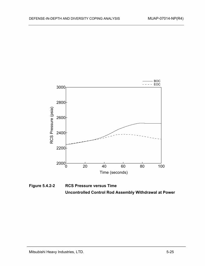
DEFENSE-IN-DEPTH AND DIVERSITY COPING ANALYSIS MUAP-07014-NP(R4)
Mitsubishi Heavy Industries, LTD. 5-25
3000
2800
2600
2400
2200
2000
RC
S P
ress
ure
(psi
a)
100806040200Time (seconds)
BOC EOC
Figure 5.4.2-2 RCS Pressure versus Time Uncontrolled Control Rod Assembly Withdrawal at Power

DEFENSE-IN-DEPTH AND DIVERSITY COPING ANALYSIS MUAP-07014-NP(R4)
Mitsubishi Heavy Industries, LTD. 5-26
620
600
580
560
540
520
RC
S A
vera
ge T
empe
ratu
re (°
F)
100806040200Time (seconds)
BOC EOC
Figure 5.4.2-3 RCS Average Temperature versus Time Uncontrolled Control Rod Assembly Withdrawal at Power
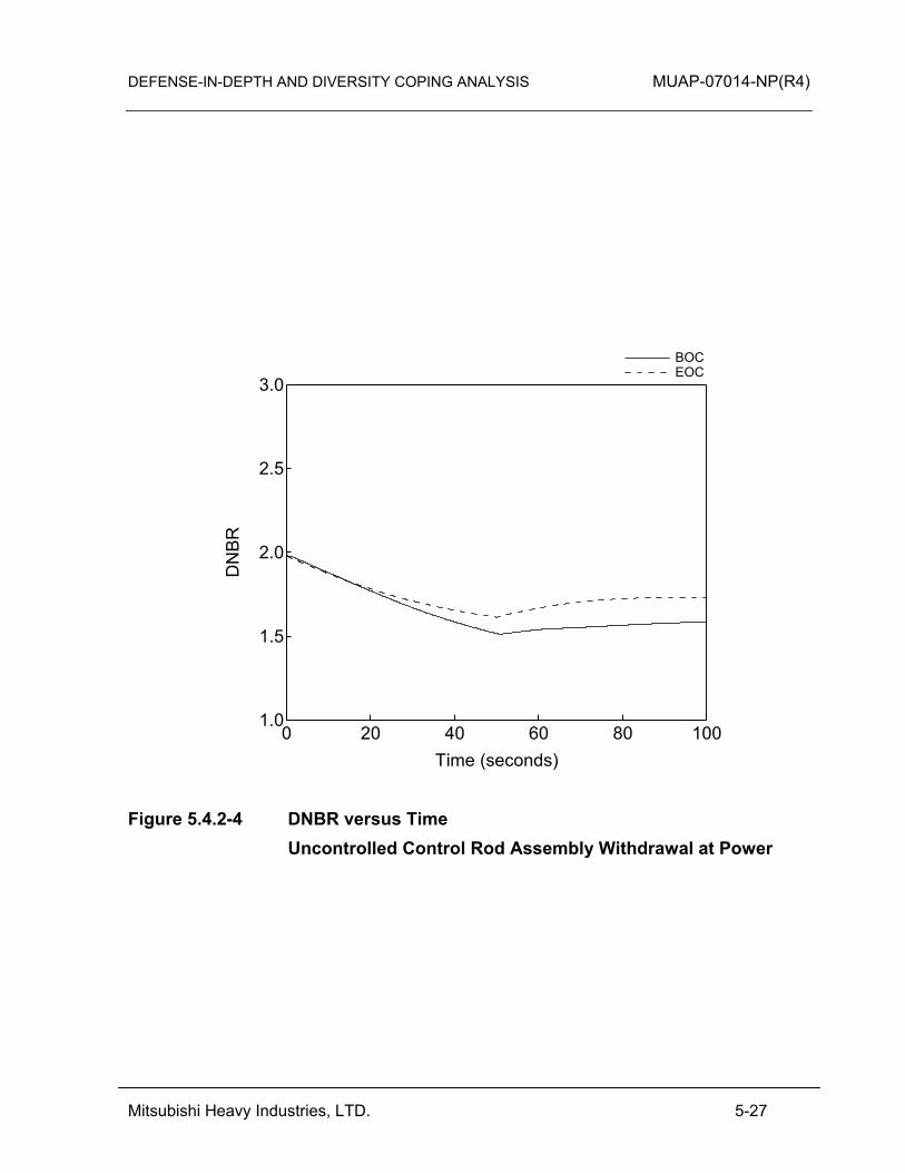
DEFENSE-IN-DEPTH AND DIVERSITY COPING ANALYSIS MUAP-07014-NP(R4)
Mitsubishi Heavy Industries, LTD. 5-27
3.0
2.5
2.0
1.5
1.0
DN
BR
100806040200Time (seconds)
BOC EOC
Figure 5.4.2-4 DNBR versus Time Uncontrolled Control Rod Assembly Withdrawal at Power
DEFENSE-IN-DEPTH AND DIVERSITY COPING ANALYSIS MUAP-07014-NP(R4)
Mitsubishi Heavy Industries, LTD. 5-28
5.4.3 Control Rod Misoperation (System Malfunction or Operator Error)
Control rod misoperation includes: • One or more dropped RCCAs within a group or bank • One or more misaligned RCCAs (relative to their bank) • Uncontrolled withdrawal of a single RCCA
Dropped or misaligned RCCAs could be caused by failures or malfunctions of an RCCA drive mechanism or RCCA drive mechanism control equipment. Movement of a single RCCA is never performed during normal operations. However, the capability to move a single RCCA exists in order to restore a dropped RCCA to its correct position under strict administrative procedural control. The misaligned RCCA event evaluation is performed as a static evaluation that is not affected by a digital I&C CCF. Therefore, only the dropped RCCA and single RCCA withdrawal events are addressed in this section. (1) Pressure Boundary Integrity
For the dropped RCCA event, DCD Section 15.4.3 in shows that the RCS pressure is not a significant adverse consequence without RTS/ESF actuation. For the single RCCA withdrawal event, the RCS pressure increase is mitigated by the pressurizer safety valve and the DAS. Therefore, the integrity of the RCPB is maintained for this event concurrent with a CCF. (2) Core Coolability
For the dropped RCCA event, DCD Section 15.4.3 shows that DNB does not occur without RTS/ESF actuation. For the single RCCA withdrawal event, the realistic reactivity inserted to the core is not more severe than the Section 5.4.2 event. So DNB is not a significant consequence without RTS/ESF actuation. Therefore, the core coolability is maintained for these events concurrent with a CCF. These events are categorized as “equivalent protection” events for core coolability. (3) Dose
The core coolability is maintained for this event concurrent with a CCF. Therefore, the dose associated with this event does not exceed 10% of the 10 CFR 100 dose guidelines for AOOs and 10 CFR 100 dose guidelines for PAs.
DEFENSE-IN-DEPTH AND DIVERSITY COPING ANALYSIS MUAP-07014-NP(R4)
Mitsubishi Heavy Industries, LTD. 5-29
5.4.4 Startup of an Inactive Loop or Recirculation Loop at an Incorrect Temperature
This section is not applicable to the US-APWR because power operation with an inactive loop is not allowed by the Technical Specifications. 5.4.5 Flow Controller Malfunction Causing an Increase in BWR Core Flow Rate
This section is only applicable to BWRs and is not applicable to the US-APWR. 5.4.6 Inadvertent Decrease in Boron Concentration in the Reactor Coolant System
An inadvertent decrease of the boron concentration in the reactor coolant can occur due to the addition of low-boron-concentration water into the reactor coolant due to a malfunction or improper operation of the chemical and volume control system (CVCS). This transient results in a positive reactivity addition to the core. (1) Pressure Boundary Integrity
The RCS pressure increase is mitigated by the pressurizer safety valve and the DAS or PCMS as explain below. Therefore, the integrity of the RCPB is maintained for this event concurrent with a CCF. (2) Core Coolability
In the case that a CCF affects the PSMS and all of the control functions of the PCMS, the transient can be considered as quasi-steady state at the reactivity insertion rate for the Uncontrolled Control Rod Assembly Withdrawal at Power event described in Section 5.4.2. For an Inadvertent Decrease in Boron Concentration in the Reactor Coolant System, the reactivity insertion rate due to dilution flow is less than the one for an Uncontrolled Control Rod Assembly Withdrawal at Power. Therefore, DNBR is almost the same as the Uncontrolled Control Rod Assembly Withdrawal at Power event when the DAS high pressurizer pressure reactor trip occurs. While the axial power distribution is conservatively assumed in the Uncontrolled Control Rod Assembly Withdrawal at Power analysis. The axial power distribution for the BOC case can be mitigated by assuming the power shape consistent with the core burn-up. For an Inadvertent Decrease in Boron Concentration in the Reactor Coolant System, the BOC case is most limiting. For this case, DNB does not occur due to the automatic reactor trip by DAS. DCD Table 15.4.6-1 shows that the time available from the alarm to loss of shutdown margin is 61.2 minutes for Mode 1 under manual rod control. Therefore, the time available in this case is 61.2 minutes for manual operator action to terminate the dilution flow. The CCF is similar to the DCD case, however, the operator will use DHP and local controls to terminate the dilution flow. Since the CCF case relies on the DAS high pressurizer pressure reactor trip which is delayed compared to the RTS trip, this

DEFENSE-IN-DEPTH AND DIVERSITY COPING ANALYSIS MUAP-07014-NP(R4)
Mitsubishi Heavy Industries, LTD. 5-30
event is categorized as an “expertly judged” event for core coolability. Because the time from the beginning of the event to the reactor trip by either PSMS or DAS is a small fraction of the time from the initiation of the transient to the return to criticality, core coolability can be adequately maintained during this event with a concurrent CCF. In this event sequence as shown in Table 5.4.6-1, the operator is to acknowledge the DAS high pressurizer pressure reactor trip alarm and to terminate dilution flow following the Special Event procedure for this event.
Table 5.4.6-1 Inadvertent Decrease in Boron Concentration in the Reactor Coolant System
in the case that a CCF in the PSMS also Affects All of the Control Functions of the PCMS
Failure mode PSMS: disabled PCMS: disabled
Prompting Alarm DAS high pressurizer pressure reactor trip actuation alarm
Operator Actions Time required Move to DHP 0.5 minutes Confirm procedure in manual 0.5 minutes Energize DHP manual controls 0.5 minutes Follow the steps in the procedure to terminate dilution flow by local control
30 minutes
Total time required 31.5 minutes In the case that the PCMS is unaffected by the CCF in the PSMS, the automatic rod control system compensates for the reactivity insertion due to boron dilution. Therefore, the core coolability is maintained. Abnormal boron dilution is mitigated by termination of dilution flow manually in MCR following the alarm same as DCD Section 15.4.6. DCD Table 15.4.6-1 shows that the time margin from the rod insertion limit alarm to loss of shutdown margin is 73.0 minutes for Mode 1 under automatic rod control. This time margin is sufficient to terminate dilution flow manually in the MCR. For this CCF condition, the same alarm is generated. However, since PSMS controls will not be available, some local control actions may be needed to terminate the dilution flow. As shown in the table above local actions require no more than 30 minutes. Therefore, 73 minutes is sufficient for all credited mitigation actions. This case is categorized as an “equivalent protection” event for core coolability. (3) Dose
The core coolability is maintained for this event concurrent with a CCF. Therefore, the dose associated with this event does not exceed 10% of the 10 CFR 100 dose guidelines for AOOs.
DEFENSE-IN-DEPTH AND DIVERSITY COPING ANALYSIS MUAP-07014-NP(R4)
Mitsubishi Heavy Industries, LTD. 5-31
5.4.7 Inadvertent Loading and Operation of a Fuel Assembly in an Improper
Position
This event is caused by administrative errors during fuel loading, and is not affected by a CCF in a digital I&C system. Therefore, this event is not analyzed in the coping analysis. 5.4.8 Spectrum of Rod Ejection Accidents
This accident is defined as the mechanical failure of a CRDM housing, which results in the ejection of a RCCA and its drive shaft. The consequence of this RCCA ejection is a rapid positive reactivity insertion with an increase of core power peaking, possibly leading to localized fuel rod failure. (1) Pressure Boundary Integrity
This event violates the integrity of RCPB as initiator similar to small break loss-of-coolant accident (SBLOCA). Therefore, the C/V integrity should be maintained. The leak flow in this event is much smaller than the SBLOCA event described in Section 5.6.5. Since, the SBLOCA represents the limiting condition, this event is categorized as an “expertly judged” event for C/V integrity. (2) Core Coolability
This event violates the integrity of RCPB as initiator similar to small break loss-of-coolant accident (SBLOCA). Therefore, the C/V integrity should be maintained. The leak flow in this event is much smaller than the SBLOCA event described in Section 5.6.5. Since, the SBLOCA represents the limiting condition, this event is categorized as an “expertly judged” event for C/V integrity. (3) Dose
This core coolability is maintained for this event concurrent with a CCF. Therefore, the dose associated with this event does not exceed the 10 CFR 100 dose guidelines for PAs. 5.4.9 Spectrum of Rod Drop Accidents in a BWR
This BWR event is not applicable to the US-APWR. 5.5 Increase in Reactor Coolant Inventory
5.5.1 Inadvertent Operation of Emergency Core Cooling System that Increases Reactor Coolant Inventory
DEFENSE-IN-DEPTH AND DIVERSITY COPING ANALYSIS MUAP-07014-NP(R4)
Mitsubishi Heavy Industries, LTD. 5-32
This section is not applicable to the US-APWR. It is not applicable because none of the components of the ECCS (safety injection pumps or accumulators) are capable of injecting water into the RCS at normal, at-power operating pressures. 5.5.2 Chemical and Volume Control System Malfunction that Increases Reactor
Coolant Inventory
A CVCS malfunction that increases RCS inventory can be caused by an operator error, a test sequence error, or an electrical malfunction. The CVCS normally operates with one charging pump running and a constant letdown flow through the letdown path. The increase of RCS inventory may be caused by an increase in charging flow with letdown operating or by isolation of the letdown path (letdown line and excess letdown line). If the CVCS boron concentration is larger than the RCS boron concentration, the reactor may experience a negative reactivity insertion resulting in a decrease in reactor power and subsequent coolant shrinkage. (1) Pressure Boundary Integrity
In the DCD Section 15.5.2, a CVCS malfunction is mitigated by termination of charging flow manually in the MCR following the high pressurizer water level alarm. For the case that a CCF in the PSMS also affects all of the control functions of the PCMS, and the case that the PCMS is unaffected by the CCF in the PSMS, the pressurizer safety valve has sufficient capacity to release the surge flow due to the charging flow if the pressurizer overfills and pressurizer safety valve opens. Therefore, RCS maximum pressure is less than the criterion for RCPB. In the case that a CCF in the PSMS also affects all of the control functions of the PCMS, the operator can detect the abnormal condition from the DAS high pressurizer pressure reactor trip actuation alarm. The operator acknowledges using local controls the DHP alarm, and then, following Special Event EOPs, terminates the charging flow using local control. The sequence of operator actions is shown in Table 5.5.2-1. The time available is more than at least 60 minutes because the pressurizer safety valve has sufficient capacity to be less than the criterion for RCPB, HFE analysis to confirm sufficient margin between time available and time required for local actions is discussed in Section 3.4.
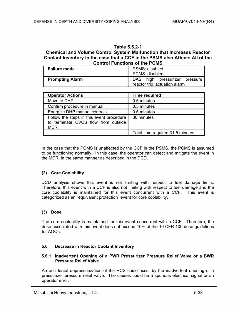
DEFENSE-IN-DEPTH AND DIVERSITY COPING ANALYSIS MUAP-07014-NP(R4)
Mitsubishi Heavy Industries, LTD. 5-33
Table 5.5.2-1
Chemical and Volume Control System Malfunction that Increases Reactor Coolant Inventory in the case that a CCF in the PSMS also Affects All of the
Control Functions of the PCMS Failure mode PSMS: disabled
PCMS: disabled Prompting Alarm DAS high pressurizer pressure
reactor trip actuation alarm Operator Actions Time required Move to DHP 0.5 minutes Confirm procedure in manual 0.5 minutes Energize DHP manual controls 0.5 minutes Follow the steps in this event procedure to terminate CVCS flow from outside MCR
30 minutes
Total time required 31.5 minutes In the case that the PCMS is unaffected by the CCF in the PSMS, the PCMS is assumed to be functioning normally. In this case, the operator can detect and mitigate the event in the MCR, in the same manner as described in the DCD. (2) Core Coolability
DCD analysis shows this event is not limiting with respect to fuel damage limits. Therefore, this event with a CCF is also not limiting with respect to fuel damage and the core coolability is maintained for this event concurrent with a CCF. This event is categorized as an “equivalent protection” event for core coolability. (3) Dose
The core coolability is maintained for this event concurrent with a CCF. Therefore, the dose associated with this event does not exceed 10% of the 10 CFR 100 dose guidelines for AOOs. 5.6 Decrease in Reactor Coolant Inventory
5.6.1 Inadvertent Opening of a PWR Pressurizer Pressure Relief Valve or a BWR Pressure Relief Valve
An accidental depressurization of the RCS could occur by the inadvertent opening of a pressurizer pressure relief valve. The causes could be a spurious electrical signal or an operator error.
DEFENSE-IN-DEPTH AND DIVERSITY COPING ANALYSIS MUAP-07014-NP(R4)
Mitsubishi Heavy Industries, LTD. 5-34
(1) Pressure Boundary Integrity
DCD Section 15.6.1 shows that the RCS pressure is not a significant adverse consequence without RTS/ESF actuation. Therefore, the integrity of the RCPB is maintained for this event concurrent with a CCF. (2) Core Coolability
DCD Figure 15.6.1-7 shows that DNB does not occur by the time the low pressurizer pressure reactor trip occurs. DCD Table 15.6.1-1 shows the analytical limit is reached at 28.3 seconds from the event occurrence and rod motion begins at 30.1 seconds. The low pressurizer pressure analytical limit for the DCD and D3 analyses are 1860 psia and 1840 psia, respectively. For this event concurrent with a CCF, the analytical limit is expected to be reached at almost the same time because the difference of the limits is quite small and the rate of pressure decrease is high. The DAS delay time of 10 seconds is greater than that of the RTS, therefore for this event concurrent with a CCF, the rod motion is expected to begin prior to 40 seconds. If the DNBR shown in DCD Figure 15.6.1-7 is extrapolated at the slope prior to trip, the DNBR will remain above the 95/95 limit at 40 seconds. Also, this evaluation is based on the conservative assumptions of DCD Section 15.6.1 for the axial power distribution and moderator temperature coefficient. Therefore, DNB does not occur and core coolability is maintained for this event concurrent with a CCF. This is “expertly judged” event for core coolability. (3) Dose The core coolability is maintained for this event concurrent with a CCF. Therefore, the dose associated with this event does not exceed 10% of the 10 CFR 100 dose guidelines for AOOs. 5.6.2 Radiological Consequences of the Failure of Small Lines Carrying Primary
Coolant Outside Containment
A failure of small lines carrying primary coolant outside containment results in radiological consequences, resulting from a release containing the radionuclide concentration of the reactor coolant. The cause may be a leak in the instrument, sample, or CVCS letdown lines due to manufacturing defect, corrosion, or maintenance activities. (1) Pressure Boundary Integrity
DCD Section 15.6.2 shows that the RCS pressure is not a significant adverse consequence without RTS/ESF actuation. Therefore, the integrity of the RCPB is maintained for this event concurrent with a CCF. (2) Core Coolability

DEFENSE-IN-DEPTH AND DIVERSITY COPING ANALYSIS MUAP-07014-NP(R4)
Mitsubishi Heavy Industries, LTD. 5-35
DCD analysis shows no fuel damage results from this transient. Therefore, this event with a CCF is also not limiting with respect to fuel damage and the core coolability is maintained for this event concurrent with a CCF. This event is categorized as an “equivalent protection” event for core coolability. (3) Dose
In the case that a CCF in the PSMS also affects all of the control functions of the PCMS, the plant trips automatically by the DAS low pressurizer pressure reactor trip. The operator acknowledges the DHP alarm and then follows the Special Event EOPs. The operator also acknowledges the DAS automatic ECCS actuation based on low-low pressurizer pressure to accommodate partial CCF conditions, as explained in Section 3.5.3. The sequence of operator actions is shown in Table 5.6.2. The Special Event EOPs will also direct the operator to terminate the leakage using local controls outside the MCR. With realistic conditions, the time available which meets the 10 CFR 100 criteria (100% for PA), from event initiation to termination of the leakage is 180 minutes. The sequence of operator actions is shown in Table 5.6.2-1. HFE analysis to confirm sufficient margin between time available and time required for local actions is discussed in Section 3.4.
Table 5.6.2-1 Radiological Consequences of the Failure of Small Lines Carrying Primary
Coolant Outside Containment in the case that a CCF in the PSMS also Affects All of the Control Functions of the PCMS
Failure mode PSMS: disabled PCMS: disabled
Prompting Alarm DAS automatic ECCS actuation alarm or DAS low pressurizer pressure reactor trip actuation alarm
Operator Actions Time required Move to DHP 0.5 minutes Confirm procedure in manual 0.5 minutes Energize DAS manual controls 0.5 minutes Follow steps in the procedure for this event to terminate break flow by local control
30 minutes
Total time required 31.5 minutes In the case that the PCMS is unaffected by the CCF in the PSMS, the operator can detect this event in the same manner as in the DCD because the PCMS is functioning correctly. The operator may recognize the CCF, when components fail to respond to PSMS manual controls. The operator can terminate the leak flow using local controls outside the MCR following special event procedures. If the event progresses to the point of reactor trip by DAS, the event sequence will be as discussed above for complete CCF of PSMS and PCMS. As discussed above, the time available which meats the 10 CFR 100 criteria
DEFENSE-IN-DEPTH AND DIVERSITY COPING ANALYSIS MUAP-07014-NP(R4)
Mitsubishi Heavy Industries, LTD. 5-36
(100% for PA), from initiation to termination of the leakage is 180 minutes. 5.6.3 Radiological Consequences of Steam Generator Tube Failure
In the steam generator tube rupture (SGTR) event, the complete severance of a single steam generator tube is assumed. The event is assumed to take place at full power with the reactor coolant contaminated with fission products corresponding to continuous operation with a limited number of defect fuels. The event leads to leakage of radioactive coolant from the RCS to the secondary system. The operator is expected to recognize the occurrence of a SGTR event, to identify and isolate the ruptured steam generator, and to take appropriate actions to stabilize the plant. These operator actions should be performed in a timely manner to minimize contamination of the secondary system and the release of radioactivity to the atmosphere. (1) Pressure Boundary Integrity
DCD Section 15.6.3 shows that the RCS pressure is not a significant adverse consequence without RTS/ESF actuation. The main steam relief valves and the main steam safety valves do not discharge into the C/V and the Safety Depressurization Valve does not discharge directly into the C/V. Therefore, the integrity of the RCPB and C/V is maintained for this event concurrent with a CCF. (2) Core Coolability
DCD analysis describes that fuel failure due to DNB occurrence is only an issue prior to reactor trip. The primary parameters of concern for DNB remain constant between the initiation of the SGTR and the reactor trip. Even if RCS pressure decreases due to the rupture of a steam generator tube, the effect of the RCS pressure reduction does not result in DNB occurrence. Therefore, the core coolability is maintained for this event concurrent with a CCF. This event is categorized as an “expertly judged” event for core coolability. (3) Dose
For an SGTR without a CCF, the N-16 alarm-PCMS is initiated and the operator manually trips the reactor using the indicators on visual display unit (VDU). These same VDU indicators are then used to identify the event as an SGTR. The following SGTR specific manual actions are then performed to mitigate the event. • Isolation of affected steam generator • Cooldown of primary coolant system • Pressure equalization between primary and secondary coolant system • Termination of injection from ECCS
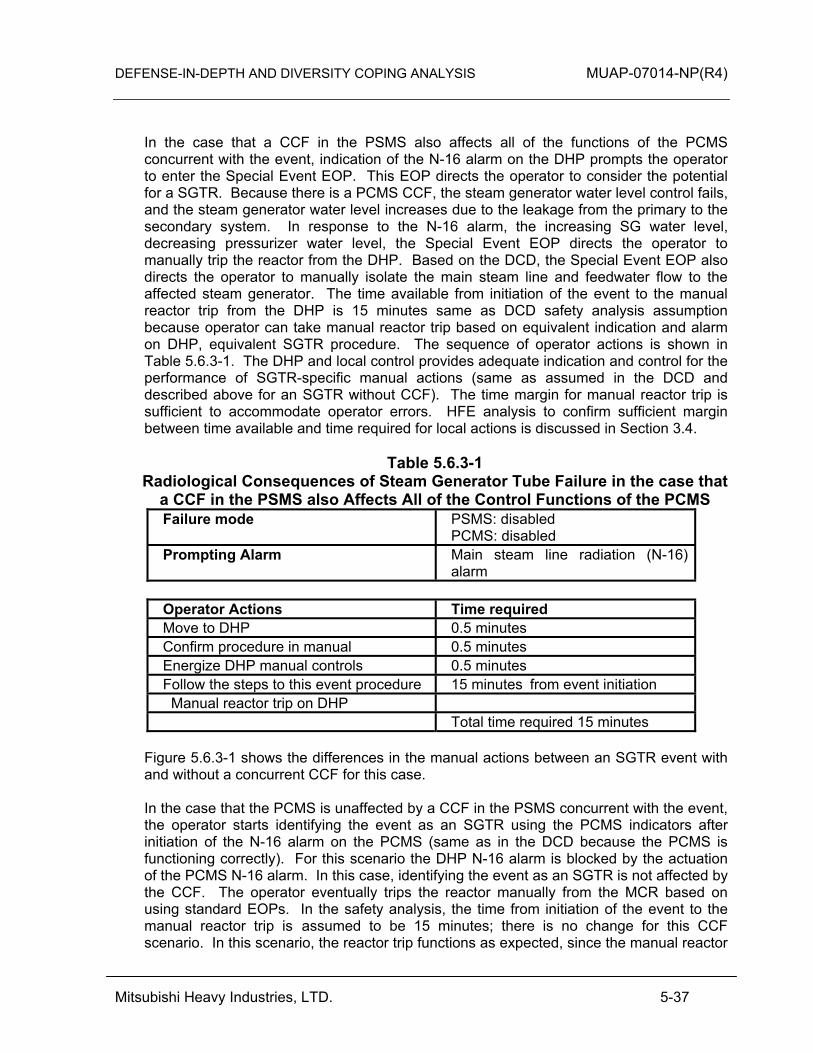
DEFENSE-IN-DEPTH AND DIVERSITY COPING ANALYSIS MUAP-07014-NP(R4)
Mitsubishi Heavy Industries, LTD. 5-37
In the case that a CCF in the PSMS also affects all of the functions of the PCMS concurrent with the event, indication of the N-16 alarm on the DHP prompts the operator to enter the Special Event EOP. This EOP directs the operator to consider the potential for a SGTR. Because there is a PCMS CCF, the steam generator water level control fails, and the steam generator water level increases due to the leakage from the primary to the secondary system. In response to the N-16 alarm, the increasing SG water level, decreasing pressurizer water level, the Special Event EOP directs the operator to manually trip the reactor from the DHP. Based on the DCD, the Special Event EOP also directs the operator to manually isolate the main steam line and feedwater flow to the affected steam generator. The time available from initiation of the event to the manual reactor trip from the DHP is 15 minutes same as DCD safety analysis assumption because operator can take manual reactor trip based on equivalent indication and alarm on DHP, equivalent SGTR procedure. The sequence of operator actions is shown in Table 5.6.3-1. The DHP and local control provides adequate indication and control for the performance of SGTR-specific manual actions (same as assumed in the DCD and described above for an SGTR without CCF). The time margin for manual reactor trip is sufficient to accommodate operator errors. HFE analysis to confirm sufficient margin between time available and time required for local actions is discussed in Section 3.4.
Table 5.6.3-1 Radiological Consequences of Steam Generator Tube Failure in the case that
a CCF in the PSMS also Affects All of the Control Functions of the PCMS Failure mode PSMS: disabled
PCMS: disabled Prompting Alarm Main steam line radiation (N-16)
alarm Operator Actions Time required Move to DHP 0.5 minutes Confirm procedure in manual 0.5 minutes Energize DHP manual controls 0.5 minutes Follow the steps to this event procedure 15 minutes from event initiation Manual reactor trip on DHP Total time required 15 minutes
Figure 5.6.3-1 shows the differences in the manual actions between an SGTR event with and without a concurrent CCF for this case. In the case that the PCMS is unaffected by a CCF in the PSMS concurrent with the event, the operator starts identifying the event as an SGTR using the PCMS indicators after initiation of the N-16 alarm on the PCMS (same as in the DCD because the PCMS is functioning correctly). For this scenario the DHP N-16 alarm is blocked by the actuation of the PCMS N-16 alarm. In this case, identifying the event as an SGTR is not affected by the CCF. The operator eventually trips the reactor manually from the MCR based on using standard EOPs. In the safety analysis, the time from initiation of the event to the manual reactor trip is assumed to be 15 minutes; there is no change for this CCF scenario. In this scenario, the reactor trip functions as expected, since the manual reactor
DEFENSE-IN-DEPTH AND DIVERSITY COPING ANALYSIS MUAP-07014-NP(R4)
Mitsubishi Heavy Industries, LTD. 5-38
trip controls are not affected by the PSMS CCF. However, the automatic turbine trip following manual reactor trip cannot function, since the PSMS CCF adversely affects the automation. Since DAS actuation is blocked only by successful reactor trip and turbine trip, the turbine immediately trips by DAS low pressurizer pressure reactor trip. The DAS low pressurizer pressure alarm alerts the operator to the CCF. This DAS alarm together with the previous PCMS N-16 alarm prompts entry into the Special Event EOP for SGTR. From this point the scenario progresses as described above for complete PSMS and PCMS failure. For both PCMS failure modes with CCF, the DAS and appropriate manual actions based on Special Event EOPs provide an event termination time that is similar to the DCD evaluation. Therefore, the 10 CFR 100 criteria are met (100% for PA). This event is categorized as an “expertly judged” event for dose. For an SGTR concurrent with CCF under realistic conditions, the time available for main steam isolation should be more than 30 minutes. Therefore, the DCD Ch.15 assumption of the manual main steam isolation within 30 minutes is conservatively applied. The DHP has manual switches to isolate the main steam line for the affected SG from the MCR.
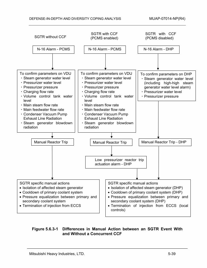
DEFENSE-IN-DEPTH AND DIVERSITY COPING ANALYSIS MUAP-07014-NP(R4)
Mitsubishi Heavy Industries, LTD. 5-39
Figure 5.6.3-1 Differences in Manual Action between an SGTR Event With and Without a Concurrent CCF
SGTR without CCF SGTR with CCF (PCMS disabled)
SGTR with CCF (PCMS enabled)
To confirm parameters on VDU ・ Steam generator water level ・ Pressurizer water level ・ Pressurizer pressure ・ Charging flow rate ・ Volume control tank water
level ・ Main steam flow rate ・ Main feedwater flow rate ・ Condenser Vacuum Pump
Exhaust Line Radiation ・ Steam generator blowdown
radiation
N-16 Alarm - PCMS N-16 Alarm - DHP
SGTR specific manual actions • Isolation of affected steam generator • Cooldown of primary coolant system • Pressure equalization between primary and
secondary coolant system • Termination of injection from ECCS
Manual Reactor Trip Manual Reactor Trip - DHP
Low pressurizer reactor trip actuation alarm - DHP
Manual Reactor Trip
N-16 Alarm - PCMS
To confirm parameters on VDU ・ Steam generator water level ・ Pressurizer water level ・ Pressurizer pressure ・ Charging flow rate ・ Volume control tank water
level ・ Main steam flow rate ・ Main feedwater flow rate ・ Condenser Vacuum Pump
Exhaust Line Radiation ・ Steam generator blowdown
radiation
SGTR specific manual actions • Isolation of affected steam generator (DHP) • Cooldown of primary coolant system (DHP) • Pressure equalization between primary and
secondary coolant system (DHP) • Termination of injection from ECCS (local
controls)
To confirm parameters on DHP ・ Steam generator water level
(including high-high steam generator water level alarm)
・ Pressurizer water level ・ Pressurizer pressure
DEFENSE-IN-DEPTH AND DIVERSITY COPING ANALYSIS MUAP-07014-NP(R4)
Mitsubishi Heavy Industries, LTD. 5-40
5.6.4 Radiological Consequences of Main Steam Line Failure Outside Containment (BWR)
This section is not applicable to the US-APWR. 5.6.5 Loss-of-Coolant Accidents Resulting from Spectrum of Postulated Piping
Breaks within the Reactor Coolant Pressure Boundary
Loss-of-coolant accidents (LOCAs) are PAs that would result from the loss of reactor coolant at a rate in excess of the capability of the normal reactor coolant makeup system. The coolant loss occurs from piping breaks in the RCPB up to and including a break equivalent in size to the double-ended rupture of the largest pipe in the RCS. The large break LOCA and small break LOCA are discussed separately in the following subsections. 5.6.5.1 Large Break Loss-of-Coolant Accident (LBLOCA)
For an LBLOCA without a CCF, the safety injection (SI) signal is automatically initiated to start the SI pumps and deliver safety injection water into the RCS. For an LBLOCA with a concurrent CCF, the DAS actuates the SI pumps automatically. (1) Pressure Boundary Integrity An LBLOCA event violates the integrity of the RCPB as the event initiator. Therefore, the event acceptance criterion is that the containment integrity should be maintained. The DAS provides the low pressurizer pressure reactor trip actuation alarm, automatic ECCS actuation alarm, and/or the containment pressure indicator to alert the operator to the potential need for manual actions to maintain containment integrity after SI actuation. For LBLOCA, the pressurizer pressure decreases rapidly to reach the automated ECCS actuation setpoint. This results in the DAS SI actuation and a DHP alarm. The operator continues to check the plant parameters on the DHP for preparation of containment spray actuation. The time available from the reactor trip actuation alarm to manual actuation of containment spray is more than 24 hrs. Within this duration the containment pressure is maintained less than the ultimate pressure of 216 psia. This time is sufficient for manual actuation of containment spray using local controls. HFE analysis to confirm sufficient margin between time available and time required for local actions as discussed in Section 3.4. The US-APWR Probabilistic Risk Assessment, MUAP-07030 (Reference 10) shows that it (2) Core Coolability
For LBLOCA, pressurizer pressure decreases rapidly to reach the reactor trip setpoint and also the SI pump shutoff head. The DAS actuates the SI pumps automatically.
DEFENSE-IN-DEPTH AND DIVERSITY COPING ANALYSIS MUAP-07014-NP(R4)
Mitsubishi Heavy Industries, LTD. 5-41
(a) Analysis Assumptions, Input Parameters and Initial Conditions The assumptions, input parameters, and initial conditions assumed in the D3 coping analysis are the same as the DCD Chapter 15 safety analysis (LBLOCA Reference Case); however, the start time of the water injection into the reactor vessel by the SI pumps is delayed by the time associated with DAS actuation. (b) Results Figure 5.6.5.1-1 plots peak cladding temperature (PCT) versus time. As shown in Figure 5.6.5.1-1, the cladding temperature is maintained sufficiently low for LBLOCA, if the water injection into the reactor vessel by the SI pumps starts within 6 minutes (time available) from the beginning of the break. The DAS ECCS actuation analytical limit reaches at least 10 seconds after the beginning of the break. After that, the DAS can provide automatic ECCS actuation within at least 128.0 seconds (including time delay from pump starting to full flow). Therefore, the DAS automatic ECCS actuation can maintain core coolability.
(3) Dose
LBLOCA event assuming CCF does not result in significant consequence to the core coolability. Therefore, the dose associated with this event does not exceed the 10 CFR 100 dose guidelines for PAs.
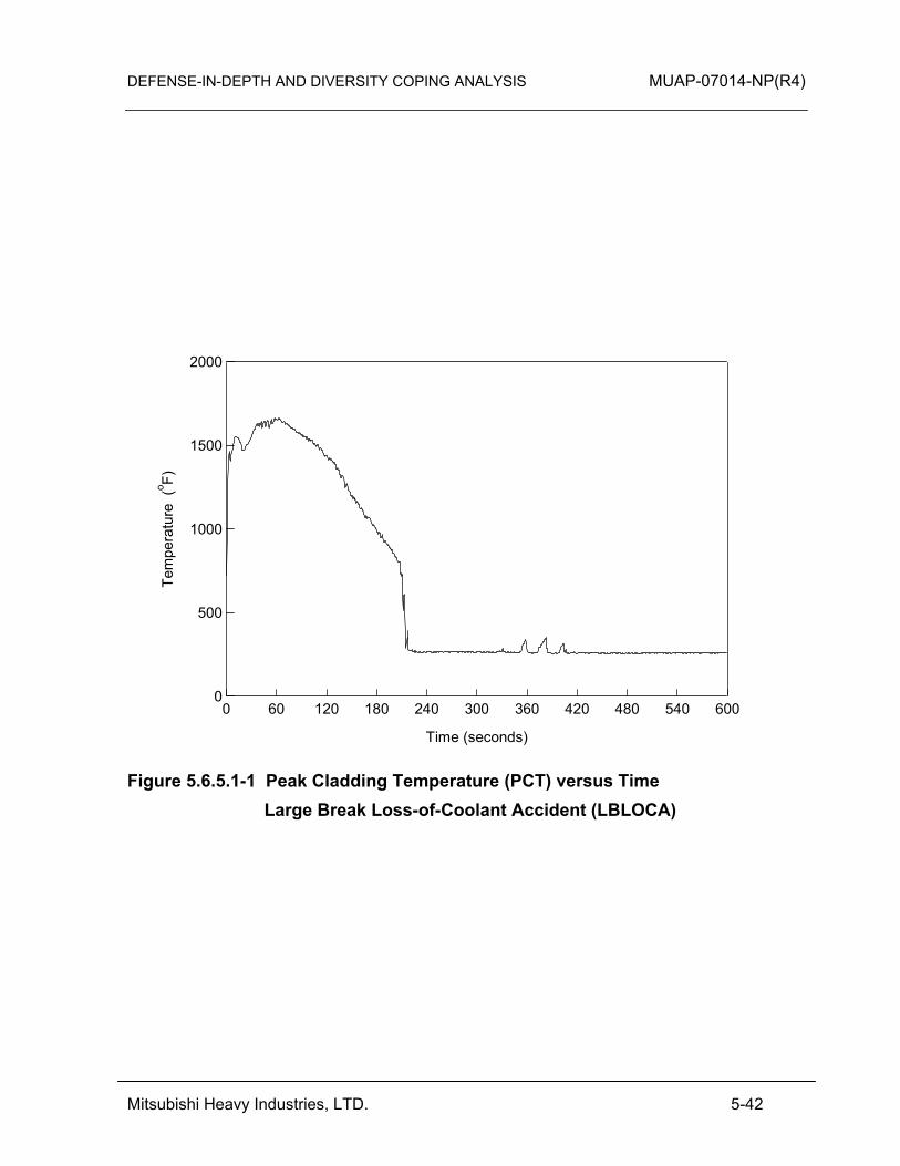
DEFENSE-IN-DEPTH AND DIVERSITY COPING ANALYSIS MUAP-07014-NP(R4)
Mitsubishi Heavy Industries, LTD. 5-42
2000
1500
1000
500
0
Tem
pera
ture
(o F)
600540480420360300240180120600
Time (seconds)
Figure 5.6.5.1-1 Peak Cladding Temperature (PCT) versus Time
Large Break Loss-of-Coolant Accident (LBLOCA)
DEFENSE-IN-DEPTH AND DIVERSITY COPING ANALYSIS MUAP-07014-NP(R4)
Mitsubishi Heavy Industries, LTD. 5-43
5.6.5.2 Small Break Loss-of-Coolant Accident (SBLOCA)
For an SBLOCA without a CCF, the safety injection (SI) signal is automatically initiated to start the SI pump and deliver safety injection water into the RCS. For an SBLOCA with a concurrent CCF, the DAS automatically starts the SI pumps.
(1) Pressure Boundary Integrity
An SBLOCA event violates the integrity of the RCPB as the event initiator. Therefore, the event acceptance criterion is that the containment integrity should be maintained. For SBLOCA, the pressurizer pressure decreases rapidly to reach the reactor trip setpoint and also the SI pump shutoff head. The DAS starts the SI pumps based on low-low pressurizer pressure. After the SI pumps are automatically started along with the actuation alarm on the DHP, the operator continues to check the plant parameters on the DHP. The time available from the reactor trip actuation alarm to manual actuation of the containment spray is more than 24 hrs. Within this duration the containment pressure is maintained less than the ultimate pressure of 216 psia. This time is sufficient for manual actuation of the containment spray using local controls. HFE analysis to confirm sufficient margin between time available and time required for local actions as discussed in Section 3.4. The US-APWR Probabilistic Risk Assessment, MUAP-07030 (Reference 10) shows that it The DAS provides the low-low pressurizer pressure ECCS actuation alarm and/or the containment pressure indicator to alert the operator to the potential need for manual actions to maintain containment integrity after ECCS actuation. This event is categorized as an “expertly judged” event for containment integrity.

DEFENSE-IN-DEPTH AND DIVERSITY COPING ANALYSIS MUAP-07014-NP(R4)
Mitsubishi Heavy Industries, LTD. 5-44
(2) Core Coolability
For SBLOCA, pressurizer pressure decreases rapidly to reach the reactor trip setpoint and also the SI pump shutoff head. The DAS automatically starts the SI pumps based on low-low pressurizer pressure before the core is uncovered. Therefore, the DAS automatic ECCS actuation can maintain core coolability. This event is categorized as an “expertly judged” event for core coolability. (3) Dose
SBLOCA event assuming CCF does not result in significant consequence to the core coolability. Therefore, the dose associated with this event does not exceed the 10 CFR 100 dose guidelines for PAs.
DEFENSE-IN-DEPTH AND DIVERSITY COPING ANALYSIS MUAP-07014-NP(R4)
Mitsubishi Heavy Industries, LTD. 6-1
6.0 CONCLUSION
This technical report describes MHI’s approach to demonstrate the D3 coping analysis for the I&C systems applied to the US-APWR. In the D3 coping analysis, the safety functions of the digital safety system are assumed to be disabled by a CCF, either in part or completely. Mitigating functions of the control system that use the same digital platform are assumed to be either disabled by the same CCF or unaffected. The DAS provides diverse automatic reactor/turbine trip, diverse automatic emergency feedwater actuation, and diverse safety injection actuation which are not impaired by the postulated CCF. The DAS also provides manual actuation functions and plant parameter monitoring functions which can be used to cope with CCFs. Available components and plant conditions assumed in the analysis are established in a best estimate manner considering beyond design basis situations. The D3 coping analysis confirms that using equipment that is not affected by the CCF (i.e., the DAS and local controls), operators are capable of coping with a CCF in the digital safety system that occurs concurrent with US-APWR DCD Chapter 15 safety analysis events (AOOs/PAs) in terms of the pressure boundary integrity, the coolability and the radiation release based on the CCF acceptance criteria. The analysis also shows the ability to meet the ATWS criteria for the DCD Chapter 15 events assuming a CCF.
DEFENSE-IN-DEPTH AND DIVERSITY COPING ANALYSIS MUAP-07014-NP(R4)
Mitsubishi Heavy Industries, LTD. 7-1
7.0 REFERENCES
In this section, references referred to within this technical report, except for applicable codes, standards and regulatory guidance in Section 2, are enumerated. 1. Safety I&C System Description and Design Process, MUAP-07004-P Rev.7
(Proprietary) and MUAP-07004-NP Rev.7 (Non-Proprietary), May 2011. 2. Safety System Digital Platform -MELTAC-, MUAP-07005-P Rev.7 (Proprietary) and
MUAP-07005-NP Rev.7 (Non-Proprietary), April 2011. 3. Defense-in-Depth and Diversity, MUAP-07006-P-A Rev.2 (Proprietary) and
MUAP-07006-NP-A Rev.2 (Non-Proprietary), September 2009. 4. HSI System Description and HFE Process, MUAP-07007-P Rev.3 (Proprietary) and
MUAP-07007-NP Rev.3 (Non-Proprietary), October 2009. 5. Non-LOCA Methodology, MUAP-07010-P Rev.1 (Proprietary) and MUAP-07010-NP
Rev.1 (Non-Proprietary), October 2010. 6. Thermal Design Methodology, MUAP-07009-P (Proprietary) and MUAP-07009-NP
(Non-Proprietary), May 2007. 7. Requirements for reduction of risk from anticipated transients without scram (ATWS)
events for light-water-cooled nuclear power plants, 10 CFR 50.62. 8. Guidance for Evaluation of Diversity and Defense-in-Depth in Digital Computer-Based
Instrumentation and Control Systems, BTP 7-19, March 2007. 9. Policy, Technical, and Licensing Issues Pertaining to Evolutionary and Advanced Light-
Water Reactor (ALWR) Designs, SECY-93-087, April 1993. 10. US-APWR Probabilistic Risk Assessment, MUAP-07030-P Rev.3 (Proprietary), June
2011. 11. Swain, A.D. and Gutman H. E., "Handbook of Human Reliability Analysis with
Emphasis on Nuclear Power Plant Applications", NUREG/CR-1278, August 1983 12. American Nuclear Society, "Time Response Design Criteria For Safety Related
Operator Actions", ANSI/ANS-58.8-1994, La Grange Park, Illinois, 1994. 13. Large Break LOCA Code Applicability Report for US-APWR, MUAP-07011-P Rev.1
(Proprietary) and MUAP-07011-NP Rev.1 (Non-Proprietary), March 2011.