![HEAT-BASED AUTOMATED ON-THE-ROAD PAINTING MACHINEeprints.utm.my/.../1/MusaMailah2017_Heat-BasedAutomatedon-the-Road.pdf · documents [8–11]. The overall information related to the](https://static.fdocuments.us/doc/165x107/5e8923e492bdad2736042664/heat-based-automated-on-the-road-painting-documents-8a11-the-overall-information.jpg)
URBAN ADMINISTRATION AND DEVELOPMENT DEPARTMENT Volume 3 Road.pdf · ROAD & BRIDGE WORKS INFORCE...
124
GOVERNMENT OF MADHYA PRADESH, URBAN ADMINISTRATION AND DEVELOPMENT DEPARTMENT INTEGRATED STANDARD SCHEDULE OF RATES (4 VOLUMES) VOLUME - 3 ROAD & BRIDGE WORKS INFORCE FROM 1st JUNE 2011 ISSUED BY COMMISSIONER Urban Administration and Development Department Government of Madhya Pradesh, Bhopal
Transcript of URBAN ADMINISTRATION AND DEVELOPMENT DEPARTMENT Volume 3 Road.pdf · ROAD & BRIDGE WORKS INFORCE...

GOVERNMENT OF MADHYA PRADESH, URBAN ADMINISTRATION AND DEVELOPMENT DEPARTMENT
INTEGRATED STANDARD SCHEDULE OF RATES (4 VOLUMES)
VOLUME - 3
ROAD & BRIDGE WORKS
INFORCE FROM
1st JUNE 2011
ISSUED BY
COMMISSIONER
Urban Administration and Development Department Government of Madhya Pradesh, Bhopal

FOREWORD
The 74th Constitutional Amendment has created a focus on improving and strengthening
Urban infrastructure and systems in Urban Local Bodies. With the availability of
substantial funds from various sources and with our own increased revenues, shortage
of development funds is no longer a major constraint for development. However
ensuring the effective utilization of available funds is a major concern.
Procurement processes in the Urban Local Bodies is one such area which requires
basic system improvement and transparency. Estimating the cost of works correctly
prior to the execution is one of the major challenges. Till now, Urban Administration and
Development Department, Government of Madhya Pradesh did not have its own
Standard Schedule of Rates which forms a basis for estimating the costs of various
Building and Infrastructure works including Water Supply, Drainage, Road, Sewerage
and Sanitation and Electrical Works. Presently Urban Local Bodies have to depend on
Schedule of Rates of various Works Departments of the State Government such as MP
Public Health Engineering Department, Public Works Department, Water Resource
Department etc. for civil works and Madhya Pradesh State Electricity Board for electrical
works. The infrastructure and maintenance works done by our Urban Local Bodies are
town specific as well as need specific and therefore, new items are required to be
created which are currently not mentioned in these SoRs. Hence the Department of
Urban Administration and Development has decided to develop its own Integrated
Standard Schedule of Rates for all Building and Infrastructure and maintenance works
keeping in view the current and future requirements of the Urban Local Bodies.
I am extremely happy that the Department, with the assistance of Project Utthan,
Madhya Pradesh Urban Services for the Poor (MPUSP), a DFID assisted programme
has taken up this task and have completed it.
To complete this task, a 18 member Working Group was formed vide order number
;kaiz/7/09/2442 dated 12th October 2009. This Working Group decided about the various
items required by Urban Local Bodies to carry out the infrastructure development and
construction works smoothly, and to be included in the ISSR.

The ISSR is prepared in four parts i.e. Volume - 1 Water Supply, Sewerage & Tube well
works, Volume - 2 Building works, Volume - 3 Road & Bridge works, Volume - 4
Electrical works. Specifications for various works have also been illustrated in three
separate volumes.
An Output Review Panel was also constituted vide order number
MPUSP/Engg./SSRs/10/439, Bhopal Dated 23-7-2010. The Output Review Panel
reviewed the process outputs and finalized various reports including Rate Analysis for
various items under Integrated Standard Schedule of Rates.
All the volumes of the ISSR along with the applications are also available on the
Website of UADD (mpurban.gov.in). Arrangements have been made for annual
updation of the ISSR. This will help the Urban Local Bodies in preparing cost estimates
close to the prevailing market values and hence, avoid high tender rates.
I extend my sincere thanks to the Project Director, Project Utthan, MPUSP, UADD,
Bhopal and to all the members of Working Group and the Output Review Panel for
taking keen interest in completing the voluminous job of preparation & completion of
ISSR well in time.
I am sure that this Integrated Standard Schedule of Rates will be quite useful for all the
construction, development and maintenance works of Urban Local Bodies of Madhya
Pradesh.
(S.N. Mishra) Commissioner
Urban Administration and Development Government of Madhya Pradesh
Bhopal

MEMBERS OF WORKING GROUP
1. Shri K. K. Shrivastava, Chief Engineer, Directorate of Urban
Administration and Development, Bhopal
Chairman
2. Shri C. S. Sankule, Chief Engineer, Project Uday, Department of Urban
Administration and Development, Bhopal
Member
3. Shri Ashok Khare, Superintending Engineer, Directorate of Urban
Administration and Development, Bhopal
Member
4. Shri R.N. Songara, Superintending Engineer, Directorate of Urban
Administration and Development, Bhopal
Member
5. Shri S.K. Sogani, Superintending Engineer, Deputy Director office,
UADD, Jabalpur
Member
6. Shri J.M. Dagaonkar Superintending Engineer, Municipal Corporation,
Ujjain
Member
7. Shri H.K. Jain Superintending Engineer, Municipal Corporation, Indore Member
8. Shri S.K. Devgan Deputy City Engineer, Municipal Corporation, Bhopal Member
9. Shri K.K. Shrivastava Executive Engineer, Municipal Corporation,
Gwalior
Member
10. Shri B.K. Sonwani, Executive Engineer, Deputy Director office, UADD,
Sagar
Member
11. Shri A.G. Khan, Executive Engineer, Deputy Director office, UADD,
Bhopal
Member
12. Shri Avinash Dubey Incharge Executive Engineer., Deputy Director
office, UADD, Rewa
Member
13. Shri Pradeep Nigam Incharge Executive Engineer, Deputy Director
office, UAD, Indore
Member
14. Shri Anand Singh, Assistant Engineer, Directorate of UAD Member
15. Shri Rakesh Rawat, Assistant Engineer, Municipal Council,
Hoshangabad
Member
16. Shri P.P. Kaithwas, Assistant Engineer, Municipal Council, Neemuch Member
17. Shri J.P. Gupta Former Deputy Director (Engineering) MSU, MPUSP,
UADD, Bhopal
Member
Secretary
18. Shri S.K. Goyal Engineering Consultant MPUSP Technical
Consultancy Team, Bhopal
Member

MEMBERS OF OUTPUT REVIEW PANEL
1. Shri Ashok Khare, Chief Engineer (In Charge), Directorate
of Urban Administration and Development, Bhopal
Chairman
2. Shri M.J.S Tulsi, Deputy Director (Engineering), Project
Utthan, Municipal Support Unit, MPUSP, Department of
Urban Administration and Development, Bhopal
Convener
3. Shri Kamlesh Bhatnagar, Assistant Engineer, Project
Utthan, Municipal Support Unit, MPUSP, Department of
Urban Administration and Development, Bhopal
Special Invitee
4. Shri Shyam Mehndi Ratta, Engineering Consultant, MPUSP
Technical Consultancy Team, Bhopal
Member
5. Shri Sunil Koul, Engineering Consultant, MPUSP Technical
Consultancy Team, Bhopal
Member
6. Shri Harsh Vardhan Sharma, Engineering Consultant,
MPUSP Technical Consultancy Team, Bhopal
Member
7. Shri Sanjay Saxena, E-Governance Consultant, MPUSP
Technical Consultancy Team, Bhopal
Member
8. Shri Ashwin Lamba, E-Governance Consultant, MPUSP
Technical Consultancy Team, Bhopal
Member

Chapter
No. Description Page No.
ROAD
GENRAL NOTES 1 - 11
1 Carriage of Material 12
2 Site Clearance 13 - 16
3 Earth work, Erosion control and Drainage 17 - 23
4 Sub-Bases, Bases (Non-Bituminous) and Shoulders 24 - 31
5 Bases and Surface courses (Bituminous) 32 - 54
6 Cement Concrete Pavements 55 - 62
7 Geosynthetics and Reinforced Earth 63 - 66
8 Traffic Signs, Marking & other Road Appurtenances. 67 - 73
9 Supply of Material 74
10 Maintenance of Roads 75 - 78
11 Horticulture for Roads 79 - 81
12 Survey & Investigation,Preparation of D.P.R. and other
Miscellaneous items.
82
BRIDGE
13 Foundations 83 - 90
14 Sub-Structure 91 - 100
15 Super-Structure 101 - 107
16 River Training and Protection works 108 - 110
17 Repair and Rehabilitation 111 - 114
INDEX

1
VOLUME - I Water Supply, Sewerage & Tube Well Works
VOLUME - II Building Works
VOLUME - III Road & Bridge Works
VOLUME - IV Electrical Works
2
1 Cast Iron Pipes and Specials with with Socket & Spigot lead joints.
2 Cast Iron Tyton Pipes with Tyton Joints.
3 Cast Iron Pipes and Specials with flanged joints.
4 Ductile Iron Pressure Pipes and Special with Tyton joints.
5 Unplasticized PVC Pipes & Fittings for potable water supply.
6 Cast Iron Valves.
7 Galvanised Iron Pipes, Specials and Gun Metal/Brass Metal Fittings.
8 HDPE Pipes and Specials.
9 GRP Pipes and Specials.
10 Asbestos Cement Pressure Pipe and Cast Iron Fittings.
11 Salt Glazed Stoneware Pipes.
12 Unplasticized Non-Pressure Polyvinyl Chloride (PVC-U) Pipes for use in underground sewerage
system.
13 Reinforced Cement concrete Pipes.
14 Sewer Appurtenances.
15 Civil Works for Water Supply & Sewerage works.
16 Miscellaneous.
17 Drawings for Water Supply & Sewerage.
18 Drilling of Tube Wells.
1 Carriage of Material
2 Earth work
3 Mortars
4 Concrete work
5 Reinforced Cement Concrete
6 Brick work
7 Stone work
8 Marble work
9 Wood Work & P.V.C. Works
10 Steel work
11 Flooring
12 Roofing and Ceiling
13 Finishing
14 Repair to Building
15 Dismantling & Demolishing
16 Pile work
17 Aluminium work
18 Water proofing
19 Horticulture & Landscaping
20 Form Work
The SOR of UADD Department consists of 4 Volumes
The contents of each Volume are given below
GENERAL NOTES
BUILDING WORKS
VOLUME - II
WATER SUPPLY, SEWERAGE AND TUBE WELL WORKS
VOLUME - I
2

21 Hire Charges of Machine
22 Rainwater Harvesting, Recycle and Reuse wastewater
23 Building Water Supply
24 Building Drainage
25 Sanitary Installation
1 Carriage of Material
2 Site Clearance
3 Earth work, Erosion control and Drainage
4 Sub-Bases, Bases (Non-Bituminous) and Shoulders
5 Bases and Surface courses (Bituminous)
6 Cement Concrete Pavements
7 Geosynthetics and Reinforced Earth
8 Traffic Signs, Marking & other Road Appurtenances
9 Supply of Material
10 Maintenance of Roads
11 Horticulture
12 Survey & Investigation, Preparation of D.P.R. and other Miscellaneous items
13 Foundations
14 Sub-Structure
15 Super-Structure
16 River Training and Protection works
17 Repair and Rehabilitation
1 Wiring in surface /concealed rigid P.V.C. conduit system.
2 Wiring in surface /concealed rigid Steel conduit system.
3 Wiring in surface rigid P.V.C. casing capping system
4 Wiring in existing/conduit/P.V.C. casing capping system
5 Sub Mains in surface/concealed rigid steel conduit system.
6 Rewiring in existing conduit.
7 Control switch gear/Bus bar.
8 MCCB’s, Isolators, MCB’s, MCB-DB and fixing.
9 Accessories/Pannel/Lamp/Telephone wires/Fens/Luminaries.
10 Miscellaneous
11 Earthing
12 Dismantiling of Civil and Electrical Works.
13 External Electrification and Over head lines
14 Power Cable & laying
15 Transformers. & Fire Extinguishers
16 High Mast
17 Pump Sets with G.I. Pipe
18 Solar street light system
19 Supply of materials
PART – 2 – EXTERNAL ELECTRIFICATION
BRIDGE
ROAD & BRIDGES WORKS
VOLUME - III
ROAD
VOLUME - IV
ELECTRICAL WORKS
PART – 1 – INTERNAL ELECTRIFICATION
3
3
3.1
3.2
3.3
3.4
3.5
4
5
6
7
8
8.1
8.2
8.3
8.4
8.5
8.6
Make of cement shall be got approved by the Engineer-in-charge. The engineer in charge shall get
cement tested as per relevant IS codes, at the cost of the contractor, before use in work.
Material,labour, templates, tools, hire and running charges of plant/machinery required to complete the
work,unless specified otherwise.
The mode of measurements shall be as per provisions contained in the relevant chapters and in
specifications/relevant IS codes.
All materials shall conform to the relevant prevailing Indian Standard Specifications. All material before
use in works shall require approval of the Engineer in charge, who will get them sampled, tested as per
relevant IS code at contractor's cost and samples so approved shall be kept in the office of the
concerned Engineer-in-charge till finalization of the work.
Where contract provides for cement to be arranged by the Contractor himself, only I.S.I. Marked
cement as per IS for 33 grade cement, IS 269 for 43 grade cement, IS 8112 for 53 grade cement, IS
12269 for Portland Pozzolana cement, IS 1489 Part - I & II specifications shall be allowed to be used in
the work subject to the prescribed tests.
Curing wherever required including arrangement of water and also including its lead or lift whatsoever.
All lead & lift of all material required for execution of work inclusive of charges like
duties,tax,royalty,insurance etc.
Provision for erection and removal of centering, form works, scaffolding, benching ladders and all other
applications etc.,required for the proper execution of the work unless otherwise specified.
Provision for covering necessary to protect the work/structure from inclement weather etc.and damage
arising from falling materials, rain,fire etc shall be the responsibility of contractor.
When the strength of concrete required upto M-30, then O.P.C. 33 grade conforming to IS 269-1989 or
P.P.C. conforming to IS : 1489-1991 may be used.
For prestressed concrete works where the strength of concrete required is more than M-30, then
O.P.C. 53 grade cement conforming to IS : 12269-1987 shall be used.
Cement :-
Hard Rock available from excavation, shall be used for conversion into coarse aggregates or for other
construction material and shall be issued to the contractor on the rate as decided by competent
authority.
When the strength of concrete required is more than M-30, the O.P.C. 43 grade conforming to IS :
8112-1989 shall be used.
Rate for completed items include the cost of followings: -
Material obtained from excavation shall be the property of the Local body (Municipal Corporation,
Municipal Council & Nagar Panchayat).
Pozzolona cement is now being widely produced all over the country. This may be used in structures as
per provisions of IS code.
4

8.7
8.8
8.9
8.10
8.11
9
9.1
9.2
9.3
9.4
9.5
10
Steel :-
Steel used for reinforcement shall conform as per under :-
(a) Mild Steel and medium tensile steel bars shall conform to IS : 432 (Part-I),
(b) Hot rolled deformed bars shall conform to IS : 1139,
(c) Cold twisted bars shall conform to IS : 1786,
(d) Hard drawn steel wire fabric shall conform to IS : 1566 and
(e) Rolled steel made from structural steel shall conform to IS : 226.
The arrangement for necessary equipment and testing shall have to be made by the contractor himself
at site, as decided by the Engineer-in-Charge. All expenses shall be borne by the contractor.
The original register shall also be submitted to the Engineer-in-Charge on completion of the work by the
Contractor.
A duplicate register as prescribed by the competent authority of technical authority shall be maintained
at the site of the work. Extract certified copies of the entries for each month shall be submitted to the
Engineer-in-Charge by the Contractor.
Any lot of cement brought to site by the contractor, would be permitted to be used in the work only after
the satisfactory results of the tests, under the supervision of the Engineer-in-Charge or his authorised
representative. The record of the test results shall be maintained in register mentioned in subsequent
para.
All reinforcement shall be free from loose mill scales, loose rust and coats of paints, oil, mud or other
coatings which may destroy or reduce bond.
The Contractor shall have to produce Test Certificate in the proforma prescribed approved by B.I.S.
from the manufacturer for every batch of steel brought to the site of work.
Only such steel obtained from main producers of steel i.e. SAIL, IISCO, TISCO or such steel rolling
mills as having licence from the B.I.S. to manufacture such steel for reinforcements, shall be allowed to
be used in the work. The make of the steel shall be approved by engineer-in-charge.
In specific cases requiring higher grade of strength, use of Ordinary Portland Cement (OPC) should be
invariably ensured.
Before commencement of use of steel, from any batch brought to site the of the work by the contractor,
the Engineer-in-Charge shall arrange to get samples tested for nominal mass, tensile strength, bend
test and rebend test from any Laboratory of his choice at the cost of Contractor. The selection of test
specimens and frequency shall be as per relevant I.S. specification of the steel used.
If any item of work is found not upto the prescribed standard but the Engineer-in-charge is of the
opinion that the same is structurally adequate and can be accepted at a reduced rate, then in such
case, the Engineer-in-charge shall submit proposal for the same, supported by an analysis in
justification thereof, through proper channel to the chief engineer UADD to obtain his approval
expeditiously (ordinarily within 15 days). The approved analysis along with orders of the chief engineer
should be appended to the final bill of the contractor.
5

11
12
13
14
15
16
16.1
16.2
16.3
Interpretations :- The Chief Engineer, UADD, Bhopal shall be the sole deciding Authority as to the
meaning, interpreation and implications of various provisions in this schedule of rates. His decision
shall be final and binding on all concerned.
Safety :- The contractor shall be fully and solely responsible for making all the safety arrangements
pertaining to the work. The contractor shall be fully responsible and liable in all respects for any
accidents and subsequent legal action initiated by any party including the department.
Latest I.S. Codes with upto date amendments shall be applicable.
In case of any contradiction in the provisions of the specifications and this schedule of rates, the
decision of Chief Engineer, UADD will be of precedence.
Note:
(i) At least one sample shall be taken from each shift.
(ii) Where concrete is produce as continuous production unit, such as ready mix concrete plant. The
frequency of sampling may be agreed upon mutually by suppliers and purchasers.
Test specimen
Concrete Work : -
Testing of Concrete :- The concrete shall be sampled in accordance with the norms specified in IS 456.
The frequency of sampling is given below.
(a) Rates of items would apply for work order/piece work system also.
(b) Rates payable for any work to be done departmentally then rates should be reduced by 10.434%
(contractor profit percentage 10% + T&P charge 2%) i.c. 100x12/115 = 10.434%.
Three test specimen shall be made for each sample for testing at 28 days. Additional samples may be
required for various purposes such as to determine the strength of concrete at 7 days or at the time of
striking the formwork, or to determine the duration of curing, or to check the testing error. Additional
samples may also be required for testing samples cured by accelerated methods as described in IS
9103. The specimen shall be tested as described in IS 516.
Nominal mix concrete may be used for concrete for M-20 or lower. The proportions of material for
nominal mix concrete shall be in accordance with the table given below: -
6

16.4
17
18
1
2
3
4
5
6
1 10% for contractor profit
2 2% for T&P
3 3% for over head charges
7
8
Extra Notes For Road Work
The rates include all cleaning operation. The rates also include provision of coir rope being used for
premix carpet and surface dressing for providing support to edges.
The rates also include the element of testing of samples of various materials brought by the contractor
for use on the work, as well as other necessary tests for items of work as stipulated in the UADD
specifications of road & bridge & MORTH specification.Frequency of such tests to be carried out must
not be less than the prescribed frequencies. Copies of registers,containing records of tests shall have
to be presented along with running account bills.Register (original) shall have to be submitted along
with the inal bill. Actual consumption of materials like bitumen,cement & steel worked out in each
running bill before making payment. Tests shall have to be conducted by the contractor's Engineer
under the supervision of the Engineer-in- Charge or his authorised representatives.
The rates include making arrangement of traffic as per MORTH clause 112 except for initial treatment
to verge, shoulders and construction of diversion.
The rates for completed items in the schedule of rates also include the following.
The labour rate only provided in the Schedule of Rates includes the cost of all labour, including
necessary handling of the materials at site of work, all workmanship unless otherwise specified.
Rates of site clearance include jungle clearance levelling and dressing.
All wood obtained from the tree shall be property of the government and shall be handed over to
Engineer in charge.
The girth of trees shall be measured at 1.00 meter (One meter) above ground level.
Design mix concrete is preferred to nominal mix. If design mix concrete can not be used for any reason
on the work for grades of M-20 or lower. Nominal mixes may be used with the permission of Engineer
in charge, which, however, is likely to involve a higher cement content.
Best shall mean that in the opinion of the concerned Engineer-in-Charge, there is no superior material
or article or class of workmanship obtainable in the market.
The labour only provided in the Schedule of Rates includes the cost of all labour including necessary
handling of the materials at site of work and all workmanship. The labour rates adopted for preparation
of S.O.R. are inclusive of provision for weekly holiday.
Note:-
The proportions of the fine to coarse aggregate should be adjusted from upper limit to lower limit
progressively as the grading of fine aggregate become finer and the maximum size of coarse
aggregate becomes lower. Granded coarse aggregate shall be used.
7

8.1
8.2
8.3
9
10
11
12
13
14
For WBM Grade-I and Grade-II broken stone can be used, for WBM Grade-III crushed stone shall be
used.
Specification of UADD Department for road & bridge and specification for road & bridge published by
I.R.C. of MORTH works shall be applicable.
As Per MORTH Table No.500-28
For construction of reinforced earth retaining wall, back filling shall be paid separately as per Chapter-3
"Earth work, erosion control and drainage"
For comprehensive items, quantities of aggregates, screenings, granular materials and binding
materials etc. indicated in the specifications are loose. No extras on account of any voids or bulkages
etc. will be paid separately. Where it is proposed only to supply, transport and stack the mineral then
aggregates payment for the same shall be regulated on the basis of volumes to be computed after
deductions specified as below. The stacking will have to be in a trapezoidal section having base 1.5 M.,
top width 0.5 M. and height 0.5 M. The length should be as long as conveniently possible.
If tests are not conducted to the prescribed frequency, the Engineer in- Charge should reject that part of
the work.
The work should not be accepted in any case, if the contractor fails to observe the instructions of the
department, regarding testing of materials.
The contractor shall have to establish a field laboratory at the site of work, if the amount of contract
exceeds Rs.25.00 lakhs.In other cases, testing of construction materials should be got done from any
of the tests laboratories of the various Government Departments, Government/Semi Govt. under
takings and Technical Institutes, Engineering College, Polytechnic, I.T.I, recognized and authorized lab.
Before making any payment, it will be the responsibility of the officers making payment to assure that all
tests as per prescribed frequencies, have been carried out, and found as per requirement. The
frequency for CBR Test is one test per 500 cum or part there of. The frequency for deleterious material
is also one test per 500 cum or part thereof.
Metal to be used for all bituminous courses and cement concrete shall be crushed in mechanical
crushers.
The use of vibratory roller is essential for all the items where ever compaction/consolidation is to be
done with rollers unless specified otherwise.
8

15
16
17
18
(a)
(b)
19
20 For items of BUSG (Built-Up Spray Grout), surface dressing and seal coat type-A, the aggregates shall
be stacked at site, measured and recorded in M.B. prior to their use on work. No separate payment
shall be made for stacking and payment for these items. These items shall be regulated as per SOR
items.
Wherever an existing boulder soling or WBM pavement is required to be excavated, it shall be
presumed that the following quantities of rubble and coarse aggregates would be available for re-use
and issued to the contractor at the rate decided by competent authority for technical sanction.
For each compacted cubic meter items of bituminous, base and surface courses the approximate loose
quantities required will be 1.4 cubic meter unless other wise specified.
W.B.M: - 1 cubic meter of W.B.M for every cubic meter of excavated WBM ( Excavated W.B.M should
be screened to segregate metal from moorum before re-use.)
Rubble: - 1 cubic meter of rubble for every cubic meter of excavated boulder soling .
The work of shoulders must proceed the work of sub-base and base courses and succeed the
bituminous courses and cement concrete pavement.
The measurements of rock excavation are to be done as per MORTH clause 301.8. However, if the
excavated rock is utilized by conversion into aggregates also, then a deduction at the rate of 45% shall
be made from the stacked quantity of aggregates. To compute the volumes of rock excavation size of
the stacks should be as large as convenient.
The surface regularity of the completed sub-grade, sub-base, base courses, widening of surfaces and
bituminous courses in the longitudinal and transverse directions shall be within the tolerances indicated
in the table below of the specifications. For checking, specifications UADD or MORTH clause 902 shall
apply.
9

21
22
23
24
25
26
27
28
29
Extra Notes for Bridge Works :-
1 Foundation :
(i)
(ii)
2 Sub Structure
The actual quantities of materials shall be as per job mix formula for bituminous works.
The pavement camber or cross fall shall be provided as per provisions of IRC-73-1980.
Dismantling of utilities will be done under the supervision of concerned departments with prior
information to the users.
For narrow and restricted areas, plate compactors shall be used for compaction to achieve the desired
density.
Bitumen & modified bitumen shall be obtained from reputed oil refineries and emulsion should be ISI
marked only.
Where laying of open graded premix carpet (OGPC) or seal coat Type-B with mechanical mixing is not
feasible, use of other Mixers are a must for open graded premix carpet or seal coat Type 'B' using
bitumen/emulsion, but this can be used only with prior approval of chief engineer UADD.
Reflective sign board should not be installed on M.D.R. and on any other road having traffic intensity
less than 450 commercial vehicles per day without prior approval of the competent authority for
sanction.
Only cement of required specifications at the rate of 2% by weight of total aggregate will be used as
filler for bituminous work wherever filler is to be provided. Lime shall not be used as filler.
Rates for the items of semi-dense bituminous concrete, dense bituminous macadam and bituminous
concrete are based on the assumption that the bitumen at the rate of 5%, 4.25% and 5% respectively
would be required. In case, lesser or more bitumen is required as per the job mix formula. Difference of
bitumen shall be paid or deducted as per actual consumption of quantity of bitumen.
All works below ground level or low water level, whichever is higher but not above soffit level shall be
termed as foundation work.
Low water level shall be the average water level met with at the time of doing the foundation work. The
maximum and minimum water levels should be recorded by the Assistant Engineer, just before starting
the particular foundation and within a reasonable time at the close of that foundation work, the average
of these two levels will be the L.W.L. for that foundation work. In case of major bridges such records will
be taken by the Executive Engineer.
The part of the bridge structure below the
(a)Soffit level of the deck slab/beams and or
(b)Springing level for arch spans, but above the ground level or L.W.L. which ever is higher, shall be
taken as sub structure of the bridge part. Complete RCC box section will also be considered as sub-
structure.
10
3 Super Structure
4 Definitions
5 Concrete :
(a) Major Bridge : Having total length between abutments at cap level 60 M.
and above.
(b) Medium Bridge : Having total length between faces of abutments at cap
level, 6 M. and above but less than 60 M.
(h) A mix leaner than M-15 may be used for non structural parts of the Bridge as specified in Approved
design/drawing.
(i) The rates of concreting items include the cost of form work and centering.
(c) Culverts : Having total length less than 6 M.
(a) All concrete shall be invariably mixed in mechanical mixers. All concrete except the concrete laid
under water, shall be mechanically vibrated.
The work above
(a)Soffit level for deck slabs/beams and
(b)Springing level for arch span, including kerbs, railing, expansion joints, beams, slabs etc. shall be
termed as super structure of the bridge part.
(b) The rates of both ordinary and controlled concrete of any mix include the cost of preparing and
testing concrete cubes as per specifications laid down.
(c) All concrete shall be compacted to produce dense and homogeneous mass with the assistance of
vibrators unless otherwise permitted by the Engineer-in-Charge for exceptional cases, such as
concreting under water where, vibrators can not be used.
(d) Concrete poured under water shall be provided with 10% additional cement as per "Specifications
for Roads & Bridges works" Ministry of Road Transport & Highway (4th Revision)
(e) Finishing of concrete by plastering the surface shall not be done without obtaining written
permission from the Executive Engineer. No extra for plastering shall be payable. Light touching up and
rubbing the uneven surfaces by carborandum stone shall be done within the specified rates.
(f) The grading, size, quality of coarse aggregates shall be strictly according to the specifications and
respective IRC Codes.
(g) The size and quality of aggregate, mixing etc. for plain concrete or R.C.C. work should be as given
in "Specification UADD/MORTH/PWD B&R.
(j) Super plasticizer admixtures should be used for the concrete work to improve the workability with
reduced water cement ratio and shall be provided as per clause 1705 of specifications.
11

6 Masonry Work
7
(iii) Generally for all stone masonry subjected to exposure of water flow (e.g. piers, abutments, returns
etc.) C.R. Masonry first sort shall be used unless otherwise provided in the approved drawing.
(iv) In case where width of stone masonry is more than one meter, the central portion of stone masonry
(Hearting) shall be done with uncaused random rubble masonry. Payment for the C.R. Masonry will be
limited to 1/2 meter width on either faces and the balance will be paid as uncaused Random Rubble
Masonry.
The measurement of rock excavation are to be done as per clause specified in the volume
"Specification of Road and Bridge works" of UADD/updated MORTH specification. All serviceable rock
excavated shall be issued to the contractor at the rate decided by competent authority for Technical
sanction.
(i) All the stone masonry work shall be strictly as per detailed specifications given in "Specification for
Road & Bridge works" of UADD/MORTH/PWD B&R.
(ii) In place of stone headers, precast or cast-in-situ concrete headers may be permitted with following
condition :
(a) If the cement is supplied departmentally and the cost of cement is recoverable from the contractor
due allowance for the actual quantity of cement consumed in the use of cement concrete headers shall
be permitted in cement consumption statement but no extra payment for providing cement concrete,
headers shall be payable.
12

Item
No.Descriptions Unit Rate Rs
Loading and unloading of stone boulder / stone aggregates / sand / kanker /
moorum. (Placing tipper at loading point, loading with front end loader, dumping,
turning for return trip, excluding time for haulage and return trip)
(Volume to be computed as per provisions of IS:1200)
1.1 Transportation of metal
i) For a lead upto 1 Km. cum 62.00
ii) For a lead upto 2 Km. cum 69.00
iii) For a lead upto 3 Km. cum 75.00
iv) For a lead upto 4 Km. cum 81.00
v) For a lead upto 5 Km. cum 86.00
vi) Beyond 5 Kms. and upto 10 Kms. (Add for every 1 Km) cum 5.00
vii) Beyond 10 Kms. and upto 20 Kms. (Add for every 1 Km) cum 4.00
viii) Beyond 20 Kms. and upto 50 Kms. (Add for every 1 Km) cum 3.00
ix) Beyond 50 Kms. (Add for every 1 Km) cum 3.00
1.2 Transportation of different other material Rate as % of
metal
a) Marble, Kota Stone cum 18%Above
b) Masonry Stone cum 18 % Above
c) Rubble cum 18 % Above
d) Loose moorum/sand/earth/surkhi. cum As Metal
e) Excavated Earth cum 25 % Above
f) Excavated ordinary rock measured cum 100 % Above
g) Cement Tonne 11 % Below
h) Steel Tonne 11 % Below
i) Timber/ ballies /planks/scantalies.etc cum 14 % Above
j) Coal /fuel ,Iron work / steel / G.I.Sheets / pipes / lime / machinary etc. Tonne 11 % Below
k) 150mm dia ballies cum 14 % Above
l) Tar/paints/Bitumen etc. cum As Metal
1.3 Transportation by trucks on hire
i) Loading of trucks cum 20.00
ii) Unloading of trucks and stacking. cum 20.00
iii) Trucks hired for full load excluding loading/unloading and stacking for items not
covered above for distances :
a) Upto 15 Kms. cum 42.00
b) Beyond 15 Kms. and upto 50 Kms. add extra over a) above cum 25.00
c) Beyond 50 Kms. add extra over b) above. cum 23.00
1.4 Unloading and stacking etc. at the railway yard from wagons.
a) Cement M.T. 34.00
b) Iron/steel/G.I. Sheet/pipes/machinary M.T. 30.00
CHAPTER-1
CARRIAGE OF MATERIALS
12

CHAPTER- 2
SITE CLEARANCE
1 The work include cutting removing & disposing and all material such as bushes, shrubs, stumps,
roots, grass, weeds, top organic soil not exceeding 150 mm in thickness , rubbish etc. Which in
the opinion of the Engineer in charge are unsuitable for incorporation in the work. From the
complete area of road land.
2 The work include necessary excavation back filling of pits resulting from uprooting of trees and
stumps to required compaction, handling ,salvaging, and disposal of cleared materials.
3 Before starting the work contractor shall submit to the engineer in charge for approval his work
plan including the procedure to be followed for disposal of waste material.
4 All branchs of trees extending above the roadway shall be trimmed as directed by Engineer.
5 All materials arising from clearing and grubbing operations shall be the property of Government
and shall be disposed of by the contractor as here in after provided or directed by the Engineer
in charge.
6 Pipe line, sewers, cables, shall be protected from injury or damage.
7 Material obtained by dismantling shall be stacked are disposed as per the direction Engineer-in-
Charge.
8 Site clearance shall be done as per MORTH clause 200
9 Rates
Rates include labour & equipment for completion of items.
Rates of cutting trees above 300 mm include excavation and back filling to the required
compaction handling and disposing of the materials.
Notes for Specification :-
(For Detail Refer specification Chapter of Site Clearance and MORTH specification of the same)
13

Item
No.Descriptions Unit Rate Rs
2.1 Cutting of trees, including cutting of trunks, branches and removal of stumps,
roots, stacking of serviceable material with all lifts and up to a lead of 1000 mtrs
and earth filling in the depression/pit and as per relevant clauses of section-200
for
i) Girth from 300 mm to 600 mm each 130.00
ii) Girth beyond 600 mm to 900 mm each 243.00
iii) Girth beyond 900 mm to 1800 mm each 457.00
iv) Girth above 1800 mm each 851.00
2.2 Clearing and grubbing road land including uprooting rank vegetation, grass,
bushes, shrubs, saplings and trees girth up to 300 mm, removal of stumps of
trees cut earlier and disposal of unserviceable materials and stacking of
serviceable material to be used or auctioned up to a lead of 1000 meter including
removal and disposal of top organic soil not exceeding 150 mm in thickness if
required and as per relevant clauses of section-200.
a) In area of light jungle hectare 25247.00
b) In area of thorny jungle hectare 33870.00
2.3 Dismantling of existing structures like culverts, bridges, retaining walls and other
structure comprising of masonry, cement concrete, wood work, steel work,
including T&P and scaffolding wherever necessary, sorting the dismantled
material, disposal of unserviceable material and stacking the serviceable material
with all lifts and lead upto 1000 meter and as per relevant clauses of section-200
in
(i) Concrete
I By Manual Means
a) Lime Concrete, cement concrete grade M-10 and below cum 200.00
b) Cement Concrete Grade M-15 & M-20 cum 233.00
c) Prestressed / Reinforced cement concrete grade M-20 & above cum 568.00
(ii) Tile work/brick masonry
a) In lime mortar cum 134.00
b) In cement mortar cum 167.00
c) In mud mortar cum 120.00
d) Dry brick pitching or brick soling cum 114.00
(iii) Stone Masonry
a) Rubble stone masonry in lime mortar cum 147.00
b) Rubble stone masonry in cement mortar. cum 167.00
c) Rubble Stone Masonry in mud mortar. cum 134.00
d) Dry rubble masonry cum 127.00
e) Stone pitching/ dry stone spalls. cum 120.00
f) Boulders laid in wire crates including opening of crates and stacking
dismantled materials.cum 134.00
SITE CLEARANCE
CHAPTER- 2
14

Item
No.Descriptions Unit Rate Rs
(iv) Steel work in all types of sections upto a height of 5 m above plinth level
excluding cutting of rivet Including dismemberingtonne 662.00
(v) Scraping of bricks dismantled from brick work including stacking.
a) In lime/Cement mortar 1000
No.567.00
b) In mud mortar 1000
No.208.00
(vi) Scraping of Stone from dismantled stone masonry
a) In cement and lime mortar cum 233.00
b) In Mud mortar cum 50.00
(vii) Scarping plaster in lime or cement mortar from brick/ stone masonry sqm 8.00
(viii) Removing all type of hume pipes and stacking within a lead upto 1000
meter including earthwork and dismantling of masonry works around pipes.
a) Up to 600 mm dia meter 86.00
b) Above 600 mm to 900 mm dia meter 117.00
c) Above 900 mm dia meter 200.00
2.4 Dismantling of flexible pavements and disposal of dismantled materials up to a
lead of 1000 meter, stacking serviceable and unserviceable materials separately
and as per relevant clauses of section-200.
a) Bituminous courses cum 367.00
b) Granular courses cum 269.00
2.5 Dismantling of cement concrete pavement i/c breaking to pieces not exceeding
0.02 cum in volume and stock piling at designated locations and disposal of
dismantled materials up to a lead upto 1000 meter, stacking serviceable and
unserviceable materials separately and as per relevant clauses of section-200.
cum 901.00
2.6 Dismantling guard rails by manual means and disposal of dismantled material
with all lifts and up to a lead upto 1000 meter, stacking serviceable materials and
unserviceable materials separately and as per relevant clauses of section-200.meter 40.00
2.7 Dismantling kerb stone by manual means and disposal of dismantled material
with all lifts and up to a lead upto 1000 meter and as per relevant clauses of
section-200.meter 9.00
2.8 Dismantling of kilometer stone including cutting of earth, foundation and disposal
of dismantled material with all lifts and lead upto 1000 m and back filling of pit.
a) 5th KM stone each 187.00
b) Ordinary KM Stone each 114.00
c) Hectometer Stone each 23.00
15

Item
No.Descriptions Unit Rate Rs
2.9 Dismantling of barbed wire fencing/ wire mesh fencing including posts, foundation
concrete, back filling of pit by manual means including disposal of dismantled
material with all lifts and up to a lead of 1000 meter, stacking serviceable material
and unserviceable material separately.
meter 23.00
2.10 Dismantling of CI water pipe line 600 mm dia including disposal with all lifts and
lead upto 1000 meter and stacking of serviceable material and unserviceable
material separately under supervision of concerned department.meter 61.00
2.11 Removal of cement concrete pipe of sewer gutter upto 1500 mm dia under the
supervision of concerned department including disposal with all lifts and up to a
lead of 1000 meter and stacking of serviceable and unserviceable material
separately but excluding earth excavation and dismantling of masonry works.
meter 77.00
2.12 Removal of telephone / Electric poles including excavation and dismantling of
foundation concrete and lines under the supervision of concerned department,
disposal with all lifts and up to a lead of 1000 meter and stacking the serviceable
and unserviceable material separately.
each 83.00
16

1
2
2(a)
(ii) Macadam surfaces such as water bound and bitumen/tar bound; soling of roads, paths etc. and
hard core; compact moorum or stabilised soil requiring grafting tool or pick or both and shovel,
closely applied; gravel and cobble stone having maximum dimension in any one direction between
75 and 300 mm.
(d) Hard Rock (blasting prohibited)
Hard rock requiring blasting as described under (c) but where blasting is prohibited for any reason
and excavation has to be carried out by chiselling, wedging or any other agreed method.
(iv) Boulders which do not require blasting having maximum dimension in any direction of more than
300 mm, found lying loose on the surface or embedded in river bed, soil, talus, slope wash and
terrace material of dissimilar origin.
(c) Hard Rock (requiring blasting)
This shall comprise :
(i) Any rock or cement concrete for the excavation for which the use of mechanical plant and/or
blasting is required.
(ii) Reinforced cement concrete (reinforcement cut through but not separated from the concrete)
below ground level; and
CHAPTER- 3
EARTH WORK, EROSION
The limits of excavation shall be set out true to lines, curves, slopes, grades and sections as shown
on the drawings.
All materials involved in excavation shall be classified as below.
Notes for Specification :-
(iii) Boulders requiring blasting
(iii) Lime concrete, stone masonry in lime mortar and brick work in lime/cement mortar below ground
level, reinforced cement concrete which may be broken up with crow bars or picks and stone
masonry in cement mortar below ground level.
Soil :- This shall comprise topsoil, turf, sand silt, loam, clay, mud, peat, black cotton soil, soft shale or
loose moorum, a mixture of these and similar material which yields to the ordinary application of pick,
spade and/or shovel, rake or other ordinary digging implement. Removal of gravel or any other
nodular material having dimension in any one direction not exceeding 75 mm occurring in such strata
shall be deemed (a) to be covered under this category.
(b) Ordinary Rock (not requiring blasting) This shall include :
(i) Rock types such as laterities, shales and conglomerates, varieties of limestone and sandstone
etc., which may be quarried or split with crow bars, also including any rock which in dry state may be
hard, requiring blasting but which, when wet, becomes soft and manageable by means other than
blasting.
(e) Marshy Soil
This shall include soils like soft clays and peats excavated below the original ground level of
marshes and swamps and soils excavated from other areas requiring continuous pumping or bailing
out of water.
17

3
4
5
6
7
8
9
10
11
S.No Type of work Maximum laboratory dry unit weight when tested as per
IS:2720 (Part 8)
1 Embankments upto 3 meters height,
not subjected to extensive flooding.
Not less than 15.2 kN/m³
2 Embankments exceeding 3 meters
height or embankments of any height
subject to long periods of inundation
Not less than 16.0 kN/m³
3 Sub-grade and earthen
shoulders/verges/backfill
Not less than 17.5 kN/m³
Note:-
As per MORTH NO. 300.1
Table 1 Density Requirements of Embankment and Sub-Grade Materials.
Precautions for the protection and preservation of any or all existing roadside trees, drains, sewers or
other sub-surface drains, pipes, conduits shall be taken.
Blasting shall be done only with the written permission of competent authority.
Blasting hours shall be made to the people in vicinity and red danger flag shall be displayed
prominently in all direction during the blasting operation. The flag shall be planted 200 m from the
blasting side in all directions.
Expansive clay exhibiting marked swell and shrinkage properties shall not be used as a fill material.
After clearing the site, mark the limits of embankment by fixing better pegs and marking toe lines on
both sides at regular intervals as guides. The embankment shall be built sufficiently wider (about 300
mm on either side of Roadway) than the specified formation width so that surplus material at the
edges may be trimmed to ensure proper compaction of the edges and side slopes.
The embankment and surgrade material shall be spread in layers of uniform thickness not exceeding
200 mm compacted thickness over the entire width of embankment.
Moisture content of the material shall be checked at the site of placement prior to commencement of
compaction if found to be out of agreed limits, the same shall be made good.
Where the width of widened portions is insufficient to permit the use of conventional rollers,
compaction shall be carried out with the help of small vibratory roller/plate compactors/ power
rammers etc.The material satisfying the density requirements given below shall be used for the construction of the
embankment and the subgrade.
This table is not applicable for lightweight fill materials, e.g., cinder, fly ash etc.
The Engineer may relax these requirements at his discretion taking into account the availability of
materials for construction and other relevant factors.
The materials to be used in sub-grade should also satisfy design CBR at the dry unit weight
applicable as per table 2.
18

12
S.No. Type of work Relative compaction as percentage of Max. laboratory dry
density as per IS:2720 (Part 8)
1 Sub-grade and earthen shoulders. Not less than 97
2 Embankments. Not less than 95
3 Expansive clays.
(a) Sub-grade and 500mm portion
just below the sub-grade.
Not allowed
(b) Remaining portion of
embankment.
Not less than 90
(i)
(ii)
(iii)
13
A Borrow Material
(i)
(ii)
(iii)
(iv)
(v)
(vi)
B Compaction Control
(i)
(ii)
(iii)
Sand content [IS : 2720(part- 4)]: 2 tests per 3000 cubic meters of soil.
Plasticity test [IS : 2720 (part- 5)]: Each type to be tested, 2 tests per 3000 cubic meter of soil.
Measurement of density of compacted layer : - one test per 1000 m2
Density test [IS : 2720 (part- 8)]: Each type to be tested, 2 tests per 3000 cubic meter of soil.
Deleterious content test [IS : 2720 (part- 27)]: As and when required by the Engineer.
CRB test on material to be incorporated in the subgrade on soaked/unsoaked samples [IS :
2720 (part- 16)]: One CRB test for every 3000 cubic meter atleast or closer as and when required by
the Engineer.
Moisture content test [IS : 2720 (part- 2)]: One test for every 250 cubic meters of soil.
Compaction Requirements for Embankment and Sub-grade
As per MORTH NO. 300.2
The following test on representative samples obtained from selected area from barrow area shall be
carried out:-
The Contractor shall at least 7 working days before commencement of compaction submit
the following to the Engineer for approval:
A graph of density plotted against moisture content from which each of the values in (i) above of
maximum dry density and optimum moisture content were determined.
The dry density - moisture content - CBR relationship for light, intermediate and heavy compactive
efforts (Light corresponding to IS:2720 (Part 7). Heavy corresponding to IS:2720 (Part 8) and
intermediate in between the two) for each of the fill materials he intends to use in the sub-grade
The values of maximum dry density and optimum moisture content obtained in accordance with
IS:2720 (Part 8), appropriate for each of the fill materials he intends to use.
As per MORTH Section 900
Subgrade material when compacted to the density requirements as given below shall yield the
design CBR value of the sub-grade.
Tests During Construction
The quality control tests to be carried out during construction and their frequency shall be as given in
Table.
QUALITY CONTROL TESTS DURING CONSTRUCTION
The Determination of density shall be in accordance with IS : 2720 (part-28).
The location shall be chosen only through random sampling techniques.
19

(iv)
(v)
(vi)
14 Measurement
14.1
14.2
15 Rates
For earth work in shoulder(earthen) and in the subgrade, at least one density measurement shall be
taken for every 500 square meters for the compacted area provided further that the number of tests
in each set of measurement shall be atleast 10.In order respects, the control shall be similar to that
described earlier.
Where cross sectional measurements could not be taken due to irregular configuration of rock or
where the rock is admixed with the other classes of materials, the volumes shall be computed on the
basis of stacks of excavated rubble after making 35 per cent deduction there form. When volumes
are calculated in this manner for excavated material other than rock, deduction made will be to the
extent of 16 per cent of stacked volumes.
(For Detail Refer specification Chapter of Earth work, Erosion and MORTH specification of the same)
Rates include labour material, equipment and all operation required for the completion of items.
Excavation for roadway shall be measured by taking cross-section at suitable intervals in the original
position before the work starts and after its completion and computing the volumes in cum.
Control shall not be based on the result of any one test but on the mean value of a set of 5-10
density determination.
The number of test in one set of measurements shall be 6 (if non-destructive test are carried out, the
number of tests shall be doubled) as long as it is felt that sufficient control over barrow material and
the method of compaction is being exercised.
20

Item
No.
DescriptionsUnit Rate Rs
3.1 Excavation for roadway in soil including loading in truck for carrying of cut earth to
embankment site with all lifts and lead upto 1000 meters and as per relevant
clauses of section-300.cum 82.00
3.2 Excavation for road way in ordinary rock including loading in a truck and carrying
of excavated material to embankment site with in all lifts and leads upto 1000
meters and as per relevant clauses of section-300.cum 117.00
3.3 Excavation for roadway in hard rock (requiring blasting) by drilling, blasting and
breaking, trimming of bottom and side slopes in accordance with requirements of
lines, grades and cross sections, loading and disposal of cut road with in all lifts
and leads upto 1000 meters and as per relevant clauses of section-300.
cum 150.00
3.4 Excavation for roadway in hard rock (blasting prohibited) with rock breakers
including breaking rock, loading in tippers and disposal within all lifts and lead
upto 1000 meters, trimming bottom and side slopes in accordance with
requirements of lines, grades and cross sections and as per relevant clauses of
section-300.
cum 413.00
3.5 Excavation for roadway in hard rock with controlled blasting by drilling, blasting
and breaking, trimming of bottom and side slopes in accordance with
requirements of lines, grades and cross sections, loading and disposal of cut road
with in all lifts and leads upto 1000 meters and as per relevant clauses of section-
300.
cum 158.00
3.6 Excavation for roadway in marshy soil with hydraulic excavator including cutting
and loading in tippers and disposal with in all lifts and lead upto 1000 meters,
trimming of bottom and side slopes in accordance with requirements of lines,
grades and cross sections and as per relevant clauses of section-300.
cum 41.00
3.6.1 Excavation for roadway in marshy soil by manually with dressing, treaming of
bottom, side slopes in accordance with the requirements of lines, grade and cross
sections with including 50m lead and 1.5m lifts.Cum 66.00
3.7 Scarifying the existing granular road surface to a depth of 50 mm and disposal of
scarified material within all lifts and leads upto 1000 meters. sqm 13.00
3.8 Scarifying the existing bituminous road surface by mechanical means to a depth
of 50 mm and disposal of scarified material with in all lifts and lead upto 1000
meters.sqm 3.00
CHAPTER-3
EARTH WORK, EROSION CONTROL AND DRAINAGE
21

Item
No.
DescriptionsUnit Rate Rs
3.9 Construction of Embankment/Sub grade/ earth shoulders, as per clause 305.1.1
inclusive of operation necessary as per clause 305 & its sub-clauses, Where
required but with approved materials obtained from excavation for road
construction (vide clause 301.3.11) i/c consolidating the original ground by rolling
as directed by the Engineer-in-charge but with a maximum of 6 passes of 8-10
tonne roller & i/c compaction and maintenance of surface during construction to
ensure shedding & preventing ponding of water (clause 305.3.7), finishing i/c all
lifts but excluding scarifying existing granular/bituminous road surface vide clause
305.6.
cum 119.00
3.10 Back filling behind the facing element in reinforced earth walls with approved
material/selected soil having CBR >12 (Unless specified otherwise in the
contract) obtained from excavation of borrow pits i/c all lifts & leads i/c grading to
required slope & camber using mortar grader and compacting using vibratory
roller of 80 to 100 kN static weight to meet compection requirement of Table No.
300.2 of MORTH specification.
cum 191.00
3.11 Construction of Embankment/Sub grade/ earth shoulders, as per clause 305 & its
sub-clauses, Where required but with approved materials/soil like morrum CBR
value not less then 7% i/c all lead & lifts i/c excavation, cost of watering,
compaction and maintenance of surface during construction to ensure shedding &
preventing ponding of water (clause 305.3.6) shaping & dressing (clause
305.3.7), finishing etc. complete but excluding scarifying existing
granular/bituminous road surface vide clause 305.6.
cum 222.00
3.12 Deduct for item No 3.10 if vibratory roller / mortar grader is not used with prior
written approval of S.E.:
i) If static roller is used in place of vibratory roller. cum 13.00
ii) If mortar grader is not used. cum 13.00
3.13 Construction of unlined surface drains of average cross sectional area 0.40 sqm
in soil to specified lines, grades, levels and dimensions to the requirement of
clause 301 and 309. Excavated material to be used in embankment within a lead
of 50 meter and as per relevant clauses of section-300.
meter 33.00
3.14 Construction of aggregate sub surface drain 300 mm width x 450 mm depth with
aggregates conforming to table 300-4, excavated material to be utilised in
roadway and as per relevant clauses of section-300.meter 86.00
3.15 Construction of embankment with fly ash conforming to table 1 of IRC: SP: 58 -
2001 obtained from coal or lignite burning thermal power stations as waste
material, spread and compacted in layer of 200mm thickness each at OMC, all as
specified in IRC: SP: 58-2001 and as per approved plans and as per relevant
clauses of section-300 with lead of fly ash.
a) Upto 25 Kms. cum 235.00
b) Beyond 25 Kms. and upto 50 Kms. (Average approx. 13 km) cum 280.00
c) Beyond 50 Kms. and upto 100 Kms. cum 392.00
22

Item
No.
DescriptionsUnit Rate Rs
3.16 Excavation in all kinds of soil for drainage work by mechanical means
(Hydraulic excavator) / manual means over areas (exceeding 30cm in depth.
1.5m in width including disposal of excavated earth, lead upto 50m and lift
upto 1.5m, disposed earth to be levelled and neatly dressed.
cum 80.00
3.17 Excavation in rock for drainage work by mechanical means (Hydraulic
excavator) / manual means over areas (exceeding 30 cm in depth, 1.5m in
width including disposal of excavated earth, lead upto 50 m and lift upto 1.5 m,
disposed earth to be levelled and eatly dressed.
(a) Ordinary rock Cum 112.00
(b) Hard rock (requiring blasting) Cum 172.00
(c) Hard rock (blasting prohibited) Cum 164.00
3.18 Providing and laying non-pressure NP2 class (light duty) R.C.C. pipes with collars
jointed with stiff mixture of cement mortar in the proportion of 1:2 (1 cement: 2
fine sand) including testing of joints etc. complete.
(a) Size 300 mm dia meter RM 175.00
(b) Size 350 mm dia meter RM 224.00
(c) Size 400 mm dia meter RM 243.00
23

1
2
IS Sieve Designation
Grading I Grading II Grading III
75 mm 100 - -
53 mm 80-100 100 -
26.5 mm 55-90 70-100 100
9.5 mm 35-65 50-80 65-95
4.75 mm 25-55 40-65 50-80
2.36 mm 20-40 30-50 40-65
0.425 mm 10-25 15-25 20-35
0.075 mm 3-10 3-10 3-10
CBR Value (Minimum) 30 25 20
IS Sieve Designation
Grading I Grading II Grading III
75 mm 100 - -
53 mm 100
26.5 mm 55-75 50-80 100
9.50 mm
4.75 mm 30-Oct 15-35 25-45
2.36 mm
0.425 mm
0.075 mm (75 micron) < 10 < 10 < 10
CBR Value (Minimum) 30 25 20
3
4
Table : Grading for Close Granular Sub-base materials
As per MORTH Table 400.1
As per MORTH Table 400.2
Table : Grading for Coarse Graded Granular Sub-base materials
Per cent by Weight Passing the IS Sieve
Before laying the sub-base the subgrade shall prepared as per clause MORTH 301 or 305. The sub
grade shall be prepared be removing vegetation etc, lightly sprinkeled with water if necessary and rolled
with two passes of 80 -100 kN smooth wheeled roller.
Sub base material shall be spread on the prepared subgrade in required slope.
CHAPTER- R-4
SUB-BASES, BASES ( NON- BITUMINOUS) AND SHOULDERS
Material to be used for the work shall be natural sand, moorum, gravel, crushed stone, or combination
thereof depending upon the grading required.
Material shall be free from organic or other deleterious constituents and conform to one of the three
grading as give below:-
Notes for Specification :-
While grading in above table are in recept of close graded grannlar sub base materials, one each
maximum partical size of 75 mm, 53mm and 26.5mm, the corresponding grading for the coarse graded
materials for each of the three maximum partical sizes are given in table below
Per cent by Weight Passing the IS Sieve
24

5
5.1
6
7
8
9
10
11
12
Moisture content of the loose sub base material shall be checked as per IS 2720 (Part-2).
Each pass of the rooler shall uniformly overlap not less than one-third of the track made in the
preceding pass.
In WBM sub-base coarse aggregates shall be either crushed or borken stone, crushed slag, overburnt,
brick aggregates or any other naturally occuring aggregates such as kankar and laterite of suitable
quality.
The coarse aggregate shall be spread uniformly and evenly upon the prepared subgrade/sub base/
base to proper profile. The thickness of each compacted layer is not more than 100 mm for Grading 1
and 75 mm for Grading 2 and 3. Immediately following the spreading of the coarse aggregate, rolling
shall be started with three wheeled power rollers of 80 to 100 kN capacity or tandem or vibratory rollers
of 80 to 100 kN static weight. After the coarse aggregate has been rolled, screenings to completely fill
the interstices shall be applied gradually over the surface. Dry rolling shall be done while the screenings
are being spread so that vibrations of the roller cause them to settle into the voids of the coarse
aggregate.
After the screenings have been applied,the surface shall be copiously sprinkled with water swept and
rolled.After the application of screenings in the binding material where it is required to be used shall be
applied successively in to or more thin layers at a slow,and uniform rate.
During rolling, the grade and camber shall be checked.
The speed of the roller shall not exceed 5 km per hour.
Rolling shall be continued till the denstiy achieved is at least 98 per cent of the maximum dry desnity.
If moisture contents found as per requirement then rolling shall be done. If the thickness of the
completed layer does not exceed 100 mm, a smooth wheeled roller of 80 to 100 kN weight may be
used. For a compacted single layer upto 225 mm the compaction shall be done with the help of a
vibratory roller of minimum 80 to 100 kN static weight with plain drum or pad footdrum or heavy
pneumatic tyred roller of minimum 200 to 300 kN weight.
Rolling shall commence at the lower edge and proceed towards the upper edge longitudinally for
portions having unidirectional crossfall and shall commence at the edges and progress towards the
centre for portions having crossfall on both sides.
Carriageway is divide into separate lanes by median and at junctions and traffic is channelised by
islands.
Shoulder in a hard/paved/earthen are bick or stone block edging on either side of the pavement.
25

13
S.N
o.
Test Test Method Requirements
1 IS : 2386 (Part 4) 40 percent (Max.)
IS : 2386 (Part 4) or
IS : 5640**
30 percent (Max.)
2 IS : 2386 (Part 1) 30 percent (Max.)
*
**
***
14
As per MORTH Table No. 400.7
The Physical Requirement of Coarse Aggregate for water bound macadam for Sub Base/Base
Courses are given below: -
Aggregate may satisfy requirements of either of the two tests.
Aggregate like bricks metal, laterite etc. which get softened in presence of water shall be tested for
Impact value under wet conditions in accordance with IS: 5640.
Physical Requirement of Coarse Aggregate for Water Bound Macadam for Sub Base/Base
Courses
*Los Angles Abrasion Value
*Aggregate Impact Value
Combined Flakiness and Elongation
Indices (Total)***
As per MORTH Table No. 400.6
Or
The coarse aggragate shall be conform to one of the gradings in given table.
The requirement of flakiness index and elongation index shall be enforced only in the case of the
crushed broken stone crushed slag.
Grading requirement of coarse aggregate:-
Grading requirement of coarse aggregate
The compacted thickness for a layer with Grading I shall be 100 mm while for layer with other Grading
i.e. II & III, it shall be 75 mm
26

15
16
(i)
(ii)
(iii)
(iv)
S.N
o.
Test Test Method Requirements
1 IS : 2386 (Part 4) 40 percent (Max.)
2 IS : 2386 (Part 4) or
IS : 5640
30 percent (Max.)
3 IS : 2386 (Part 1) 30 percent (Max.)**
*
**
Grading for sereening:-
Wet mix Macadam:-
The wet mix macadam work shall consist of laying and compacting clean, crushed, graded aggregate
and granular material, premixed with water, to a dense mass on a prepared sub-grade/sub-
base/base or existing pavement as the case may be in accordance with the requirements of these
Specifications
Screening to fill voids in the coares aggregate shall generally consist of the same material as the
coarse aggregate.screening shall conform to the grading as given below: -
Grading for sereening
Or
When vibrating or other approved types of compacting equipment are used, the compacted depth of a
single layer of the sub-base course may be upto 200 mm with the approval of the Engineer in charge
As per MORTH Table No. 400.8
As per MORTH Table No. 400.10
Coarse aggregates shall be crushed stone. If crushed gravel/shingle is used, not less than 90 percent
by weight of the gravel/shingle pieces retained on 4.75 mm sieve shall have at least two fractured
faces. The aggregates shall conform to the physical requirements as given below: -
*Los Angles Abrasion Value
Aggregate may satisfy requirement of either of the two tests.
Combined Flakiness and Elongation
Indices (Total)
To determine this combined proportion, the flaky stone from a representative sample should first be
separated out. Flakiness index is weight of flaky stone metal divided by weight of stone sample. Only
the elongated particles be separated out from the remaining (non-flaky) stone metal. Elongation index
is weight of elongated particles divided by total non-flaky particles. The value of flakiness index and
elongation index so found are added up.
The thickness of a single compacted Wet Mix Macadam layer shall not be less than 75 mm.
*Aggregate Impact Value
27

(v)
17
18
19
Tpye of Construction Frequency(min.)
1 Granular One test per 200 m3
One test per 200 m3
One test per 250 m3
One test per 500 m3
As required by Engineer in charge
As required by Engineer in charge
2 Soil sub base As required by Engineer in charge
One test per 250 sq. m
One test per 500 m2
As required by Engineer in charge
3 Water Bound
MacadamOne test per 200 m
3 of aggregate
One test per 100 m3
(f) C.B.R
(a) CBR or unconfined compressive
strenght test on a set of 3 specimens.
(b) Moisture content prior to
compaction
(d) Deleterious constituents
(a) Aggregate impact value
(b) Grading
(c) Density of compacted layer
Test and their minimum frequncy for sub base and base ( AS per MORTH Section 900)
Test
(a) Gradation
(b) Atterberg limits
(c) Moisture content prior to
compaction(d) Density of compacted layer
(e) Deleterious constituents
Measurement of Payment
Rates
Rates include charges of material, labour, equipments and machineries required for completion of items
Granular sub-base shall be measured as finished work in position in cubic meters.
The protection of edges of granular sub-base extended over the full formation as shown in the drawing
shall be considered incidental to the work of providing granular sub-base and as such no extra payment
shall be made for the same.
Water bound macadam shall be measured as finished work position in cubic meters.
The grading requirement of aggregate for wet mix macadam shall be as below:-
As per MORTH Table No. 400.11
28

One test per 200 m3 of aggregate
One test per 25 m3 of binding material
One test per 100 m3 of aggregate
4 Wet mix Macadam One test per 200 m3 of aggregate
One test per 100 m3 of aggregate
One test per 200 m3 of aggregate
One test per 100 m3 of binding
material
One test per 500 m3 of aggregate
(d) Atterberg limit of binding material
(e) Atterberg limit of portion of
aggregate passing 425 micron sieve
(a) Aggregate impact value
(e) Atterberg limit of portion of
aggregate passing 425 micron sieve
(d) Atterberg limit of binding material
(c) Flakiness index and Elongation
index
(b) Grading
(c) Flakiness index and Elongation
index
(For Detail Refer specification Chapter of Sub-Base, Base (Non-Bituminous)
and
MORTH specification of the same)
29

Item
No.Descriptions Unit Rate Rs
4.1 Construction of granular sub-base by providing coarse graded material, spreading
in uniform layers with on prepared surface, mixing by mix in place method at
OMC, and compacting with vibratory roller to achieve the desired density,
complete in all respect and as per relevant clauses of section-400.
i) for grading- I Material cum 534.00
ii) for grading- II Material cum 542.00
iii) for grading-III Material cum 530.00
4.2 Laying and spreading available soil in the subgrade on a prepared surface,
pulverising, mixing the spread soil in place with rotavator with 3 % slaked lime
having minimum content of 70% of CaO, grading with motor grader and
compacting with the road roller at OMC to the desired density to form a layer of
improved sub grade complete and as per relevant clauses of section-400. (Lime
stabilisation for improving sub-grade)
(a) By Mechanical Means Cum 343.00
(b) By Manual Means cum 335.00
4.3 Providing, laying, spreading and compacting stone aggregates of specific sizes to
water bound macadam specification including spreading in uniform thickness,
hand packing, rolling with vibratory roller 8-10 tonnes in stages to proper grade
and camber, applying and brooming requisite type of screening/ binding materials
to fill up the interstices of coarse aggregate, watering and compacting to the
required density and as per relevant clauses of section-400.
(i) Grading- I
a) Using Screening Crushable type cum 802.00
b) Using Screening Type-A (13.2mm Agg.) cum 921.00
(ii) Grading- II
a) Using Screening Crushable type cum 870.00
b) Using Screening Type-A (13.2mm Agg.) cum 916.00
c) Using Screening Type-B (11.2mm Agg.) cum 970.00
(iii) Grading- III
a) Using Screening Crushable type cum 725.00
b) Using Screening Type-B (11.2mm Agg.) cum 825.00
4.3.1 Labour rate for laying, spreading and compacting stone aggregates of specific
sizes to water bound macadam specification including spreading in uniform
thickness,hand packing, rolling with 3 wheeled steel/ vibratory roller 8-10 tonnes in
stages to proper grade and camber, applying and brooming requisite type of
screening/ binding Materials to fill up the interstices of coarse aggregate, watering
and compacting to the required density.
cum 140.00
4.4 Deduction for item No.4.1, 4.2 & 4.3 if vibratory roller / mortar grader is not used
with prior written approval by S.E. :
i) If static roller is used in place of vibratory roller. cum 47.00
ii) If mortar grader is not used. cum 47.00
CHAPTER-4
SUB-BASES, BASES ( NON- BITUMINOUS) AND SHOULDERS
30

Item
No.Descriptions Unit Rate Rs
4.5 Providing, laying, spreading and compacting graded stone aggregate to wet mix
macadam specification including premixing the Material with water at OMC in
mechanical mix plant carriage of mixed Material by tipper to site, laying in uniform
layers with paver in sub- base / base course on well prepared surface and
compacting with vibratory roller to achieve the desired density and as per relevant
clauses of section-400.
cum 863.00
4.5.1 Labour rate for laying, spreading and compacting graded stone aggregate to wet
mix macadam specification including premixing the Material with water at OMC in
mechanical mix plant carriage of mixed Material by tipper to site, laying in uniform
layers with paver in sub- base / base course on well prepared surface and
compacting with vibratory roller to achieve the desired density.
cum 180.00
4.6 Filling of existing Median and Island above road level with approved material
deposited at site from roadway cutting and excavation for drain and foundation of
other structures or borrow pits, spread, graded and uncompacted including
excavation and lead upto 1000 M. and as per relevant clauses of section-400.
cum 76.00
4.7 Filling of existing median and Island above road level with approved material
brought from borrow pits including excavation and all leads, spread, sloped and
compacted and as per relevant clauses of section-400.cum 129.00
4.8 Crusher Run Macadam Base (Providing crushed stone aggregate, depositing on
a prepared surface by hauling vehicles, spreading and mixing with a motor grader,
watering and compacting with a vibratory roller to clause 410 to form a layer of
sub-base/Base)
a) By Mix in Place Method
i) For 53 mm maximum size cum 783.00
ii) For 45 mm maximum size cum 795.00
b) By Mixing Plant :
i) For 53 mm maximum size cum 956.00
ii) For 45 mm maximum size cum 970.00
4.8.1 labour rate for crushed stone aggregate, depositing on a prepared surface by
hauling vehicles, spreading and mixing with a motor grader, watering and
compacting with a vibratory roller to clause 410 to form a layer of sub-base/Basecum 111.00
4.9 Construction of Sub-base using lime - fly ash admixture with 80% granular soil,
free from organic matter/ deleterious material or clayey silts and low plasticity
clays having PI between 5 and 20 and liquid limit less than 25, 16% flyash and 4%
commercial dry lime, slaked at site or pre-slaked with CaO content not less than
50%, fly ash to conform to gradation as per clause 4.3 of IRC: 88-1984, the
minimum un-confined compressive strength and CBR value after 28 days curing
and 4 days soaking to be 7.5kg/sq, cm and 25% respectively, all as specified in
IRC: 88 and as per relevant clauses of section-400 with lead of fly ash.
a) Upto 25 Kms. cum 423.00
b) Beyond 25 Kms. and upto 50 Kms. cum 443.00
c) Beyond 50 Kms. and upto 100 Kms. cum 485.00
31

CHAPTER- R- 5
BASES AND SURFACE COURSES (BITUMINOUS)
1 Prime Coat Over Granular base: -
Prime Coat Over Granular base work shall consist of the application of a single coat of low
viscosity liquid bituminous material to a porous granular surface preparatory to the
superimposition of bituminous treatment of mix.
The bitumen primer shall be bitumen emulsion complying with IS: 8887. The viscosity and rate of
spray is given below: -
As per MORTH Table No. 500.1
2 Tack coat : -
Work of tack coat shall consist of the application of a single coat of low viscosity liquid
bituminous material to existing bituminous road surface preparatory to the superimposition of
bituminous mix, when specified in the contract or instructed by the Engineer. The binder used for
tack coat shall be bitumen emulsion complying with IS:8887.
3 Binder: -The binder shall be appropriate type of bituminous material complying with the relevant
Indian Standard (IS). Where penetration grades of bitumen are specified they shall be according
to the Indian Standard Specification IS: 73.
4 The coarse aggregates shall consist of crushed rock, crushed gravel or other hard material
retained on the 2.36 mm sieve.
5 Bituminous Macadam: - This work shall consist of construction in a single course having 50mm
to 100mm thickness or in multiple coarses of compacted crushed aggregate premixed with a
bituminous binder on a previously prepared base.
The physical requirement of coarse aggregate for bituminous macadam,dense graded
bituminous macadam, Semi dense bituminous concrete pavement layer and bituminous
concrete pavement layer are given in following tables: -
Notes for Specification :-
32

5.1 Physical Requirement For Coarse Aggregate For Bituminous Macadam: -
Table 1 Physical Requirement For Coarse Aggregate For Bituminous Macadam
As per MORTH Table No. 500.3
Notes:-
* = IS 2386 Part I
** = IS 2386 Part I
*** = IS 2386 Part IV
**** = IS 2386 Part V
***** = IS 2386 Part III
****** = IS 6241
******* = The water sensitivity test is only to be carried out if the minimum retained coating in the
stripping test is less than 95 %.1 = Aggregate may satisfy requirements of either of these two tests.
5.2 Physical Requirement For Coarse Aggregate For Dense Graded Bituminous Macadam
Table 2 Physical Requirement For Coarse Aggregate For Dense Graded Bituminous
Macadam
As per MORTH Table No. 500.8
33

Note: -
* = IS 2386 Part I
** = IS 2386 Part I
*** = IS 2386 Part IV
**** = IS 2386 Part IV
***** = IS 2386 Part V
****** = IS 2386 Part III
******* = IS 6241
******** = AASHTO T2832
1 = Aggregate may satisfy requirements of either of these two tests.
2= The water sensitivity test is only to be carried out if the minimum retained coating in the
stripping test is less than 95 %.
5.3 Physical Requirement For Coarse Aggregate For Semi Dense Bituminous Concrete
pavement layers
Table 3 Physical Requirement For Coarse Aggregate For Semi Dense Bituminous
Concrete pavement layers
As per MORTH Table No. 500.14
Note: -
* = IS 2386 Part I
** = IS 2386 Part I
*** = IS 2386 Part IV1
**** = IS 2386 Part IV1
***** = BS 812 Part 114
****** = IS 2386 Part V
******* = IS 2386 Part III
******** = AASHTO T2832
********* = IS 6241 1 = Aggregate may satisfy requirements of either of these two tests.
2= The water sensitivity test is only to be carried out if the minimum retained coating in the
stripping test is less than 95 %.
34

5.4 Physical Requirement For Coarse Aggregate For Bituminous Concrete Pavement layers
Table 4 Physical Requirement For Coarse Aggregate For Bituminous Concrete Pavement
layers
As per MORTH Table No. 500.17
Note: -
* = IS 2386 Part I
** = IS 2386 Part I
*** = IS 2386 Part IV1
**** = IS 2386 Part IV1
***** = BS 812 Part 114
****** = IS 2386 Part V
******* = IS 2386 Part III
******** = AASHTO T2832
********* = IS 6241 1 = Aggregate may satisfy requirements of either of these two tests.
2= The water sensitivity test is only to be carried out if the minimum retained coating in the
stripping test is less than 95 %.
6 Fine aggregates shall consist of crushed or naturally occuring material, or a combination of the
two, passing 2.36 mm sieve and retained on the 75 micron sieve.
7 Composition of Bituminous Mixture:- The aggregate for bituminous macadam shall be preportioned and blended to produce a uniform
mixture complying with the requirement of table number 5.
The binder content shall be within a tolerance of ± 0.3 % by weight of total mixture when
individual specimens are taken for quality control test in accordance with the provision.
35

Table 5 Composition of Bituminous Macadam
As per MORTH Table No. 500.4
8 Bitumen Penetration Macadam: -
The Work shall consist of construction of one or more layers of compacted crushed coarse
aggregates with alternate applications of bituminous binder and key aggregates in accordance
with the requirements of the specification of be used as a base course on road. subect to
requirement of the overall approved pavement design. The composition for the quantities of
materials used for this work shall be as specified in table number 6.
Table 6 Composition of Penetration MacadamAs per MORTH Table No. 500.6
Note: - If cutback bitumen is used, adjust binder quantity such that the residual bitumen is equal to the
values in table number 6.
36

9 Dense Graded Bituminous Macadam: -
This work shall consist of construction in a single or multiple layes of DBM on a previously
prepared base or sub base. The thickness of a single layer shall be 50mm to 100 mm. The
composition of dense graded bituminous macadam shall be as per table number 7.
Table 7 Composition of Dense Graded Bituminous Macadam Pavement LayersAs per MORTH Table No. 500.10
Note:-
1 The combined aggregate grading shall not vary from the low limit on one sieve to the high limit
on the adjacent sieve.
2 Determined by the Marshall method.
10 Semi dense Bituminous Concrete Pavement Layer: -This work shall consist of contruction in a single or multiple layers of semi dense bituminous
concrete on previously prepared bituminous bound surface. A single layer shall be 25mm to
100mm in thickness. The composition of Semi dense Bituminous Concrete shall be as per table
number 8. Aggregate grading and binder content when tested in accordance with IS : 2386 Part
1 the combined grading of the coarse and fine aggregate and added filler shall fall within the
limits as shown in table below in table below for grading 1 or 2 as specified in the contract.
37

Table 8 Composition of Semi dense Bituminous Concrete Pavement LayerAs per MORTH Table No. 500.15
Note:- 1 The combined aggregate grading shall not vary from the low limit on one sieve to the high limit
on the adjacent sieve.
2 Determined by the Marshall method.
* Only in exceptional circumstances, 80 - 100 penetration grade may be used, as approved by the
Engineer.
11 Composition of Bituminous Concrete Pavement Layers: - This work shall consist of contruction in a single or multiple layers of bituminous concrete on a
previously prepared bituminous bound surface. A single layers shall be 25mm to 100mm in
thickness. This work is used in wearing and profile corrective courses.The composition of
Bituminous Concrete shall be as per table number 9. Aggregate grading and binder content
when tested in accordance with IS : 2386 Part 1 the combined grading of the coarse and fine
aggregate and added filler shall fall within the limits as shown in table below for grading 1 or 2 as
specified in the contract.
38

Table 9 Composition of Bituminous Concrete Pavement LayersAs per MORTH Table No. 500.18
12 Pre-mixed bituminous materials, including, bituminous macadam, dense bituminous macadam,
semi-dense bituminous concrete and bituminous concrete, shall be prepared in a calibrated hot
mix plant of adequate capacity.
The approximate mixing, rolling and laying temperature shall be as per table number 10. The
difference in temperature between the binder and aggregate should at no time exceed 140
C. In
order to ensure uniform quality of the mix and better coating of aggregates, the hot mix plant
shall be calibrated from time to time.
Table 10 Manufacturing and Rolling Temperatures
As per MORTH Table No. 500.5
13 Bituminous materials shall be transported in clean insulated vehicles.
Built - Up Spray Grout: -
Built - Up Spray Grout shall consist of a two layer composite construction of compacted crushed
coarse aggregate with application of bituminous binder after each layer, and with key aggregate
placed on top of the second layer, in accordance with the requirement of these specifications, to
serve as a base course and in conformity with the approved drawing, or as directed by the
Engineer. The thickness of the coarse shall be 75mm.
The bitumen shall be paving bitumen of penetration grade complying with Indian Standard
Specifications for paving Bitumen IS : 73 and where permitted in the agreement an appropriate
grade of emulsion complying with IS: 887 may be used. The grading requirements for coarse
and key aggregate for built spray grout shall be as per table 11: -
39
Table 11 Grading requirement for coarse & key aggregate for built-up spray grout
As per MORTH Table No. 500.7
14 Laying shall be suspended when free standing water is present on the surface to be covered or
during the period of rain fog and dust storms . The surface on which the bituminous work is to
be laid shall be cleaned of all loose material by means of mechanical broom or ant other
approved method.
Hand Placing of pre mixed bituminous materials:-
Hand Placing of pre mixed bituminous materials shall only be permitted in the following
circumstances: -
(i) For laying regulating coarses of irregular shape and varying thickness.
(ii) In confined spaces where it is impracticable for a paver to operate.
(iii) For footways.
(iv) At the approaches to expansion joints at bridges, viaducts or other structure.
(v) The Mastic asphalt shall be laid, normally in one coat, at a temperature between 1750C and
1200C and spread uniformly by hand using wooden floats on prepared and regulated surface.
(vi) For filling of potholes.
(vii) Where directed by the Engineer.
Manual spreading of pre mixed wering aourse material or the addition of such material by hand
spreading to the paved area, for adjustment of level, such only be permitted in the following
circumstances: -
(i) At the edges of the layers of material and at gullies and manhole.
(ii) At the approaches to expansion joints at bridges, viaducts or other structure.
(iii) As directed by the Engineer.
15 Except in areas where a mechanical paver cannot access, bituminous materials shall be spread,
leveled and tamped by an approved self-propelled paving machine. As soon as possible after
arrival at site, the materials shall be supplied continuously to the paver and laid without delay.
Surface Dressing: -
(i) This work shall consist of the application of one coat or two coats of surface dressing,each coat
consisting of a layer of bituminous binder sprayed on a previously prepared, base, followed by a
cover of stone chips rolled in to form a wearing course to the requirements of the approved
drawing. The binder shall either be bitumen conforming to IS 73 or cationic bitumen emulsion
conforming to IS: 8887.
(ii) Aggregate (chips) shall be single sized clean ,hard , durable of cubical shape, free from dust and
soft or friable matter, organic or other deleterious matter and conforming to one of the grading as
per table 12: -
40

Table 12 Grading requirements for Chips for Surface Dressing
As per MORTH Table No. 500.21
(iii) Rates of Spread for Binder and Chippings: -
For the purpose of pricing the Bill of Quantities the rates of spread as per table 13: -
Table 13 Nominal Rates of Spread for Binder and Chippings
As per MORTH Table No. 500.20
Notes: -
1. These rates of spread are for pricing purpose.
2. For emulsion, these rates of spread are for the residual bitumen and appropriate adjustment
must be made to determine the total quantity.
3. Refer to Manual for Construction and Supervision of Bituminous Works for the procedure of
determining the rates of spread of binder and chips.
(iv) Application of binder:-
The application temperature for the grade of binder used shall be as per table 14 and the rate of
spray as per table 13.
Table 14 Spraying Temperatures for Binders
As per MORTH Table No. 500.22
41

16 Seal Coat: -
(i) Seal coat consist of the application of a seal coat for sealing the voids in a bituminous surface
laid to the specified levels, grade and cross fall (camber). The types of seal coat are as below: -
A Liquid seal coat comprising of an application of layer of bituminous binder followed by a cover of
stone chips.
B Premixed seal coat comprising of a thin application of fine aggregate premixed with bituminous
binder.
(ii) The quantity of bitumen per 10 square meter shall be 9.18kg for A type seal coat and for B type
seal coat the bitumen shall be 6.8kg per 10 square meter. Bitumen used shall be as per IS : 73.
Where bitumen emulsion of standard IS:8887 is used as a binder the quantities for type A and
type B seal coat shall be 15kg and 10.5kg respectively.
(iii) Aggregate for Seal Coat
a Stone Chips for Type A seal coat
The stone chips shall consist of angular fragments of clean, hard and durable rock and free from
dust, organic or other deleterious matter. Stone chip shall be 0.6 mm size defined as 100%
passing through 11.2mm sieve and retained on 2.36mm sieve. The quantity used for spreading
shall be 0.09 cubic meter per 10 square meter area.
b Aggregate for Type B seal coat
The aggregate shall be sand or grit and shall consist of clean,hard, durable , uncoated dry
particles. These shall be free from dust, soft or flaky / elongated material, organic matter or other
deleterious substances.
The aggregate shall pass 2.36mm sieve and be retained on 180 micron sieve. The quantity used
for premixing shall be 0.06 cubic meters per 10 square meters area.
17 Mastic Asphalt: -
Mastic asphalt is an intimate homogeneous mixture of selected well graded aggregates, filler
and bitumen is such proportions as to yield a plastic and void less mass, which when applied hot
can be trowel led and floated to from a very dense impermeable surfacing.
(i) The physical of binder which shall be a paving grade bitumen meting the requirements given in
table number 15.
Table 15 Requirement for Physical Properties of Binder
As per MORTH Table No. 500.29
(ii) The percentage and grading of the coarse aggregate to be incorporated in the mastic asphalts
depending upon the thickness of the finished coarse shall be as per specified in table no. 16.
42

Table 16 Grade and Thickness of Mastic Asphalt paving and Grading of Coarse
Aggregate
As per MORTH Table No. 500.30
The aggregate and fine aggregate shall be as per detail given in point number 4 and 6.
(iii) Filler for mastic asphalt: -
The filler shall be limestone powder passing the 0.075mm sieve and shall have a calcium
carbonate content of not less than 80 persent by weight when determined in accordance with IS :
1514. The grading of the fine aggregate inclusive of filler shall be as per table number 17.
Table 17 Grading of Fine Aggregates (Inclusive Filler)
As per MORTH Table No. 500.31
18 Compaction after laying the bituminous material shall commence as soon as possible after
laying. Compaction shall be done as per clause 501.6.
19 The clause 509.1 of MORTH specifies the construction of Bituminous Concrete, for use in
wearing and profile corrective courses. This work shall consist of construction in a single or
multiple layers of bituminous concrete on a previously prepared bituminous bound surface
25mm to 100 mm in thickness.
20 Measurement
(i) Prime coat & Tack coat shall be measured in terms of surface area of application in square
meters.
(ii) Bituminous macadam shall be measured as finished work in cubic meters.
(iii) Dense, Semi dense Graded Bituminous Materials and bituminous concrete shall be
measured as finished work in cubic meters.
43
21 Note for SSR item no 5.2 :-
(i) Bitumen emulsion has been provided @ 0.25,0.30,0.35 & 0.40 kg per sqm as per clause 503.8.
Payment shall be made with adjustment, plus or minus, for the variation between this quantity
and actual quantity approved by the Engineer after preliminary trials referred to in clause No.
503.4.3
22 Note for SSR item no 5.7 :-
(i) Although the rollers are required only for 3 hours as per norms of output, but the same have to
be available at site for six hours as the hot mix plant and paver will take six hours for mixing and
paving the output of 450 tonnes considered in this analysis. To cater for the idle period of these
rollers, their usage rates have been multiplied by a factor of 0.65
(ii) Quantity of Bitumen (Bitumen- 60/70 @ 4.5 % of weight of mix, Modified bitumen CRMB @ 5%
of weight of mix & Modified bitumen PMB - 40 @ 5% of weight of mix) has been taken for
analysis purpose.The actual quantity will depend upon job mix formula.
(iii) Labour for traffic control, watch and ward and other miscellaneous duties at site including
sundries have been included in administrative overheads of the contractor.
(iv) In case SDBC is laid over freshly laid tack coat, provision of broom and 2 mazdoor shall be
deleted as the same has been included in the cost of tack coat.
(v) The quantity of Bitumen to be adjusted as per job mix formula.
23 Note for SSR item no 5.15 :-
(i) The rates for 50 mm & 40 mm thick layers may be worked out on pro-rata basis.
(ii) Where tack coat is required to be provided before laying mastic asphalt, the same is required
to be measured and paid separately.
(iii) Mix design as per IS code subjected to minimum as per MORTH specification clause 5.15.
24 Test of Bituminous Construction
Test and Frequency:- The test and their minimum frequencies for different type of bituminous
work shall be as given in table. The Engineer may direct additional testing as required.
Acceptance criteria: - The acceptance criteria for tests on density and Marshall stability be
subject to the condition that the mean value is not less then the specified value plus:-
[1.65-(1.65/(No.of sample)05
]times the standard deviation
44

25 Control test for bituminous work, & their minimum feruency(As Per MORTH Section 900)
1 Test of Construction:- Prime Coat/Tack Coat/Fog Spray
(a) Test
(i) Quality of binder
(ii) Binder temperature for application
(iii) Rate of spread of binder
(b) Frequency (min.)
(i) Number of samples per lot and test as per IS : 73,IS:217 and IS:8887 as applicable.
(ii) At regular close intervals.
(iii) One test per 500m2 and not less than two tests per days
2 Test of Construction:- Seal Coat / Surface Dressing
(a) Test
(i) Quality of binder.
(ii) Aggregate impact value / los angeles abrasion value.
(iii) Flakiness index and Elongation index.
(iv) Stripping value of aggregate.
(v) Water absorption of aggregate.
(vi) Water sensitivity of mix.
(vii) Grading of aggregate.
(viii) Soundness(Magnesium and sodium sulphate)
(ix) Polished stone value.
(x) Temperature of binder at application.
(xi) Rate of spread material.
(xii) Percentage of fractured faces.
(b) Frequency (min.)
(i) Same in mentioned under serial No. 1.
(ii) One test per 50 m2 of aggregate.
(iii) -do-
(iv) Initially one set of 3 representative specimens for each source of supply. Subsequenently when
warranted by changes in the quality of aggregate.
(v) -do-
(vi) Initially one set of 3 representative specimens for each source of supply. Subsequenently when
warranted by changes in the quality of aggregate. (if required)
(vii) One test per 25 m2 of aggregate.
(viii) Initially, One determination by each method for each source of supply, then as warranted by
changes in the quality of aggregate
(ix) As required.
(x) At regular close intervals.
(xi) One test per 500 m2 of work, and not less then two tests per day.
(xii) When gravel is used, One test per 50 m2 of aggregate.
3 Test of Construction:- Open graded premix surfacing / Close- graded premix surfacing
(a) Test
(i) Quality of binder.
(ii) Aggregate impact value / los angeles abrasion value.
(iii) Flakiness index and Elongation index.
(iv) Stripping value of aggregate.
(v) Water absorption of aggregate.
(vi) Water sensitivity of mix.
(vii) Grading of aggregate.
(viii) Soundness(Magnesium and sodium sulphate)
(ix) Polished stone value.(x) Temperature of binder at application.(xi) Binder content(xii) Rate of spread material.(xiii) Percentage of fractured faces.
45

(b) Frequency (min.)
(i) Same in mentioned under serial No. 2.
(ii) Same in mentioned under serial No. 2.
(iii) -do-
(iv) Same in mentioned under serial No. 2.
(v) Same in mentioned under serial No. 2.
(vi) Same in mentioned under serial No. 2.
(vii) Same in mentioned under serial No. 2.
(viii) Same in mentioned under serial No. 2.
(ix) As required.
(x) At regular close intervals.
(xi) One test per 500 m2 ,not less then two tests per day.
(xii) Regular control through checks of layer thickness.
(xiii) Same in mentioned under serial No. 2.
4 Test of Construction:- Bituminous Macadam
(a) Test
(i) Quality of binder.
(ii) Aggregate impact value / los angeles abrasion value.
(iii) Flakiness index and Elongation index.
(iv) Stripping value
(v) Water sensitivity of mix.
(vi) Grading of aggregate.
(vii) Water absorption of aggregate.
(viii) Soundness(Magnesium and sodium sulphate)
(ix) Percentage of fractured faces.
(x) Binder content and aggregate grading
(xi) Control of temperature of binder and aggregate for mixing and of the mix at the time of laying
and rolling.
(xii) Rate of spread mixed material.
(xiii) Density of compacted layer.
(b) Frequency (min.)
(i) Same in mentioned under serial No. 1.
(ii) Same in mentioned under serial No. 2.
(iii) Same in mentioned under serial No. 2.
(iv) Same in mentioned under serial No. 2.
(v) -do-(vi) Two test per day plant both on the individual constituents and mixed aggregate from the dryer.
(vii) Same in serial No. 2.
(viii) Same in mentioned under serial No. 2.
(ix) Same in mentioned under serial No. 2.
(x) Periodic,subject to minimum to two tests per day per plant.
(xi) At regular close intervals.
(xii) Regular control through checks of layer thickness.
(xiii) One test per 250 m2 ,of area.
5 Test of Construction:- Bituminous Penetration Macadam / Built-up Spray-Grout
(a) Test(i) Quality of binder.(ii) Aggregate impact value / los angeles abrasion value.(iii) Flakiness index and Elongation index.(iv) Stripping value(v) Water absorption of aggregate.(vi) Water sensitivity of mix.(vii) Aggregate grading
(viii) Soundness(Magnesium and sodium sulphate)
(ix) Percentage of fractured faces.
(x) Temperature of binder at application.
(xi) Rate of spread of binder
46

(b) Frequency (min.)
(i) Same in mentioned under serial No. 1.
(ii) One test per 200 m2 ,of aggregate.
(iii) -do-
(iv) Same in mentioned under serial No. 2.
(v) Same in mentioned under serial No. 2.
(vi) Same in mentioned under serial No. 2.
(vii) One test per 200 m3 ,of aggregate.
(viii) Same in mentioned under serial No. 2.
(ix) Same in mentioned under serial No. 2.
(x) At regular close intervals.
(xi) Same in mentioned under serial No. 2.
6 Test of Construction:- Dense Bituminous Macadam /semi Dense Bituminous Concrete
/Bituminous Concrete
(a) Test
(i) Quality of binder.
(ii) Aggregate impact value / los angeles abrasion value.
(iii) Flakiness index and Elongation index.
(iv) Stripping value
(v) Water absorption of aggregate.
(vi) Water sensitivity of mix.
(vii) Aggregate grading
(viii) Soundness(Magnesium and sodium sulphate)
(ix) Percentage of fractured faces.
(x) Temperature of binder at application.
(xi) Rate of spread mixed material.
(xii) Stability of mix
(xiii) Water sensitivity of mix.(Retained tensile strength)
(xiv) Control of temperature of binder and aggregate for mixing and of the mix at the time of laying
and rolling.
(xv) Control of binder content and grading of the mix.
(xvi) Rate of spread of mixed material
(xvii) Density of compacted layer.
(b) Frequency (min.)
(i) Same in mentioned under serial No. 1.
(ii) Same in mentioned under serial No. 2.
(iii) -do-
(iv) Same in mentioned under serial No. 2.
(v) Same in mentioned under serial No. 2.
(vi) Same in mentioned under serial No. 2.
(vii) As required.
(viii) As required.
(ix) As required, for semi Dense Bituminous Concrete /Bituminous Concrete.
(x) Same in mentioned under serial No. 2.
(xi) One set of tests on individual contituents and mixed aggregate form the dryer for each 400
tonnes of mix subject to a minimum of two tests per plant per day.
(xii) For each 400 tonnes of mix produced, a set 3 Marshall specimens to be prepared and tests for
stability , flow value, density and void content subject to minimum of two sets being tested per
plant per day.
(xiii) Same in mentioned under serial No. 2.
(xiv) As required for the Bituminous Concrete
(xv) At regular close intervals.
(xvi) One test for each 400 tonnes mix subjects toa minimum of two tests per day.
(xvii) Regular control through checks on the weight of mixed material and layer thickness.
47

7 Test of Construction:- Mastic Asphalt
(a) Test
(i) Quality of binder.
(ii) Aggregate impact value / los angeles abrasion value.
(iii) Flakiness index and Elongation index.
(iv) Stripping value
(v) Water sensitivity of mix.
(vi) Grading of aggregate.
(vii) Water absorption of aggregate.
(viii) Soundness(Magnesium and sodium sulphate)
(ix) Percentage of fractured faces.
(x) Binder content and aggregate grading
(xi) Control of temperature of binder and aggregate for mixing and of the mix at the time of laying
and rolling.
(xii) Rate of spread of mixed material
(xiii) Hardness number
(b) Frequency (min.)
(i) Same in mentioned under serial No. 1.
(ii) Same in mentioned under serial No. 2.
(iii) -do-
(iv) -do-
(v) -do-
(vi) Two test per day plant both on the individual constituents and mixed aggregate from the dryer.
(vii) Same in mentioned under serial No. 2.
(viii) Same in mentioned under serial No. 2.
(ix) Same in mentioned under serial No. 2.
(x) Periodic,subject to minimum to two tests per day per plant.
(xi) At regular close intervals.
(xii) Regular control through checks on the weight of mixed material and layer thickness.
(xiii) One test for each 400 tonnes mix subjects toa minimum of two tests per day.
8 Test of Construction:- Slurry seal
(a) Test
(i) Quality of binder.
(ii) Film stripping test
(b) Frequency (min.)
(i) Same in mentioned under serial No. 1.
(ii) Initially one set of 3 representative specimens for each source of supply. For each source of
supply, then as warranted by changes in the quality of aggregate.
9 Test of Construction:- Cold mix
(a) Test
(i) Quality of binder.
(ii) Aggregate impact value / los angeles abrasion value.
(iii) Flakiness index and Elongation index.
(iv) Stripping value
(v) Water sensitivity of mix.
(vi) Grading of aggregate.
(vii) Percentage of fractured faces.
(viii) Water absorption of aggregate.
(ix) Soundness(Magnesium and sodium sulphate)
(x) Percentage of fractured faces.
(xi) Binder content and aggregate grading
(xii) Mix stability
48

(b) Frequency (min.)
(i) Same in mentioned under serial No. 1.
(ii) Same in mentioned under serial No. 2.
(iii) -do-
(iv) -do
(v) -do
(vi) Two test per day plant both on the individual constituents and mixed aggregate from the dryer.
(vii) Two test per day per plant
(viii) Same in mentioned under serial No. 2.
(ix) Same in mentioned under serial No. 2.
(x) When gravel is used, One test per 50 m2 of aggregate.
(xi) Periodic,subject to minimum to two tests per day per plant.
(xii) For each 400 tonnes of mix produced, a set 3 Marshall specimens to be prepared and tests for
stability , flow value, density and void content subject to minimum of two sets being tested per
plant per day.
26 Type of Binder and their use
General: -
Penetration - Is a measure of hardness of consistency and therefore of primary importance as
an indication of suitability for any particular construction on condition. This test is probably the
most important of all tests of bitumens. Penetration is measured by a standard penetrometer.
Penetration is the distance measured in units of 1/10 mm that a standard blunt-point needle will
Penetrate a sample at 25 deg. C . When the needle is loaded with 100 grams applied for 5
seconds.
The higher the penetration number the softer the bitumen. The lower the penetration, the higher
will be the melting point and lower the ductility; in other words, the harder the bitumen the higher
will be the melting point, but the ductility will be less, for the bitumen becomes more brittle the
harder it is. The harder the bitumen the quicker it sets; a soft bitumen takes comparatively a
longer time to set.
Viscosity: - Is a liquid is the property that retards flow so that higher the viscosity the slower is
the flow of the liquid. The viscosity of the binder should be selected according to the intensity of
the traffic on the road, and also the temperature in which the work is to be carried out. Low
viscosity binder can be laid cold and high viscosity binder has to be laid hot and is used in
warmer weather. A more viscous binder id specified for the more heavily trafficked roads to
resist distortion under the intense traffic and should be laid warm or hot within a few hours of
manufacture.
26.1 Bitumen Emulsion
A freely flowing liquid at ordinary temperature in which a substantial amount of bitumen or tar is
suspended in a solution of water in a finally divided and stable state. Emulsions contain about 50
to 65 percent of bitumen. Can be used an all climates and are very useful for patch repair on
bituminous surfaces. They are cold and can work with wet chipping. When emulsion is spread
on the road it “breaks” and changes from brown to black color and the water soaks in or
evaporates allowing the bitumen partials to reunite and lie on the surface. Emulsions are more
easily applied then hot binder. The performance, however, is affected to a much greater degree
by adverse weather. Become of relatively thin film of binder that remains on the road, smaller
chippings (not more then 6 mm) must be used with emulsions than with hot binder. Before the
application of emulsion the road surface should be thoroughly cleaned and slightly damped with
water and chipping spread and rolled before the emulsion has “Broken”.
49

26.2 Bitumen Cut Back
cutbacks are softened bitumen (solid bitumen thinned with a volatile distillate such as petrol,
kerosene, diesel oil or tar oil), which can be used whiteout heating or required only light heating.
Cutback bitumen is used for cold mix specification, as it will coat chipping in drum mixer.
26.3 Bitumen 60/70 (60/70 is penetration number)
This bitumen is used in very hot localities where a slightly harder grade is required.
26.4 Bitumen 80/100 (80/100 is penetration number)
Standard grade for surface paintings; premixing; grouting is graded aggregate dense surface
and seal coats.
Modified Binder
Modified Binder comprise a base binder, to which is added either natural rubber, crumb or a
polymer such as styrene-Butadiene-Styrene (SBS), Ethylene- Vinyl-Acetate (EVA) or Low
Density Polyethylene (LDPE). The purpose is to achieve a high performance binder with
improved properties, particularly at extremes of temperature.
There are two types of Modified Binder.
A CRMB ( Crumb Rubber Modified Binder)
B PMB (Polymer Modified Binder)
Above binders are used on roads having heavy traffic of heavy load.
(For Detail Refer specification Chapter of Bases and Surface Courses and
MORTH specification of the same)
50
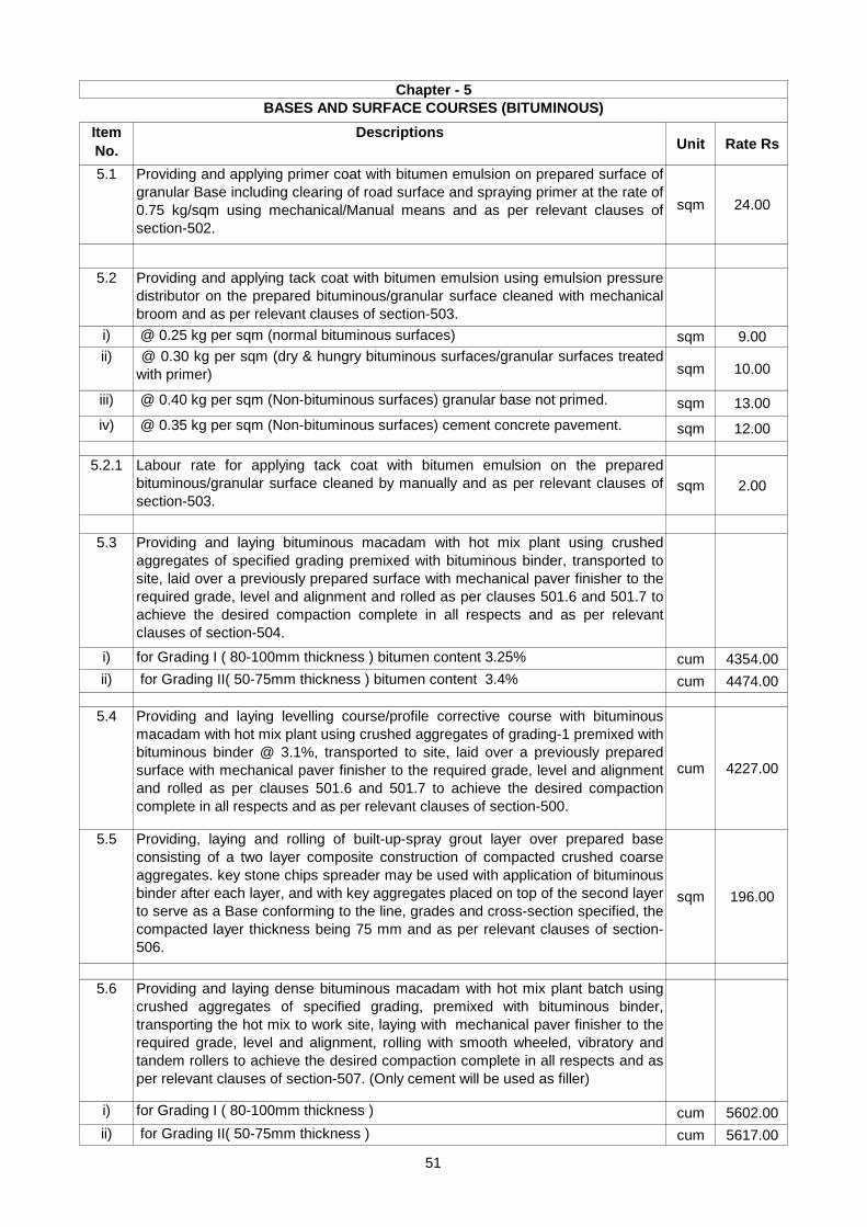
Item
No.
DescriptionsUnit Rate Rs
5.1 Providing and applying primer coat with bitumen emulsion on prepared surface of
granular Base including clearing of road surface and spraying primer at the rate of
0.75 kg/sqm using mechanical/Manual means and as per relevant clauses of
section-502.
sqm 24.00
5.2 Providing and applying tack coat with bitumen emulsion using emulsion pressure
distributor on the prepared bituminous/granular surface cleaned with mechanical
broom and as per relevant clauses of section-503.
i) @ 0.25 kg per sqm (normal bituminous surfaces) sqm 9.00
ii) @ 0.30 kg per sqm (dry & hungry bituminous surfaces/granular surfaces treated
with primer) sqm 10.00
iii) @ 0.40 kg per sqm (Non-bituminous surfaces) granular base not primed. sqm 13.00
iv) @ 0.35 kg per sqm (Non-bituminous surfaces) cement concrete pavement. sqm 12.00
5.2.1 Labour rate for applying tack coat with bitumen emulsion on the prepared
bituminous/granular surface cleaned by manually and as per relevant clauses of
section-503.sqm 2.00
5.3 Providing and laying bituminous macadam with hot mix plant using crushed
aggregates of specified grading premixed with bituminous binder, transported to
site, laid over a previously prepared surface with mechanical paver finisher to the
required grade, level and alignment and rolled as per clauses 501.6 and 501.7 to
achieve the desired compaction complete in all respects and as per relevant
clauses of section-504.
i) for Grading I ( 80-100mm thickness ) bitumen content 3.25% cum 4354.00
ii) for Grading II( 50-75mm thickness ) bitumen content 3.4% cum 4474.00
5.4 Providing and laying levelling course/profile corrective course with bituminous
macadam with hot mix plant using crushed aggregates of grading-1 premixed with
bituminous binder @ 3.1%, transported to site, laid over a previously prepared
surface with mechanical paver finisher to the required grade, level and alignment
and rolled as per clauses 501.6 and 501.7 to achieve the desired compaction
complete in all respects and as per relevant clauses of section-500.
cum 4227.00
5.5 Providing, laying and rolling of built-up-spray grout layer over prepared base
consisting of a two layer composite construction of compacted crushed coarse
aggregates. key stone chips spreader may be used with application of bituminous
binder after each layer, and with key aggregates placed on top of the second layer
to serve as a Base conforming to the line, grades and cross-section specified, the
compacted layer thickness being 75 mm and as per relevant clauses of section-
506.
sqm 196.00
5.6 Providing and laying dense bituminous macadam with hot mix plant batch using
crushed aggregates of specified grading, premixed with bituminous binder,
transporting the hot mix to work site, laying with mechanical paver finisher to the
required grade, level and alignment, rolling with smooth wheeled, vibratory and
tandem rollers to achieve the desired compaction complete in all respects and as
per relevant clauses of section-507. (Only cement will be used as filler)
i) for Grading I ( 80-100mm thickness ) cum 5602.00
ii) for Grading II( 50-75mm thickness ) cum 5617.00
BASES AND SURFACE COURSES (BITUMINOUS)
Chapter - 5
51

Item
No.
DescriptionsUnit Rate Rs
5.7 Providing and laying semi dense bituminous concrete with hot mix plant using
crushed aggregates of specified grading, premixed with bituminous binder,
transporting the hot mix to work site, laying with mechanical paver finisher to the
required grade, level and alignment, rolling with smooth wheeled, vibratory and
tandem rollers to achieve the desired compaction in all respects and as per
relevant clauses of section-508. (Only cement will be used as filler).
i) for Grading I ( 35-40 mm thickness ) with 60/70 bitumen cum 6090.00
ii) for Grading I ( 35-40 mm thickness ) with CRMB-60 cum 6174.00
iii) for Grading I ( 35-40 mm thickness ) with PMB-40 cum 6123.00
iv) for Grading II (25-30 mm thickness ) with 60/70 bitumen cum 6514.00
v) for Grading II ( 25-30 mm thickness ) with CRMB-60 cum 6636.00
vi) for Grading II ( 25-30 mm thickness ) with PMB-40 cum 6579.00
5.8 Providing and laying bituminous concrete with hot mix plant using crushed
aggregates of specified grading,premixed with bituminous binder,transporting the
hot mix to work site,laying with a mechanical paver finisher to the required
grade,level and alignment,rolling with smooth wheeled, vibratory and tandem
rollers to achieve the desired compaction in all respects and as per relevant
clauses of section-509.(Only cement will be used as filler).
i) for Grading I ( 50-65 mm thickness ) with 60/70 bitumen cum 6406.00
ii) for Grading I ( 50-65 mm thickness ) with CRMB-60 cum 6794.00
iii) for Grading I ( 50-65 mm thickness ) with PMB-40 cum 6736.00
iv) for Grading II ( 30-45 mm thickness ) with 60/70 bitumen cum 6408.00
v) for Grading II ( 30-45 mm thickness ) with CRMB-60 cum 6797.00
vi) for Grading II ( 30-45 mm thickness ) with PMB-40 cum 6738.00
5.9 Providing and laying surface dressing in single coat using crushed stone
aggregates of specified size on a layer of bituminous binder laid on prepared
surface and rolling with 8-10 tonne smooth wheeled steel roller and as per
relevant clauses of section-510.
i) with 19 mm nominal chipping size & bitumen @1.2kg per sqm. sqm 60.00
ii) with 13 mm nominal chipping size & bitumen @ 1.0 kg per sqm. sqm 50.00
5.10 Providing,laying and rolling of open-graded premix surfacing of 20mm thickness
composed of 13.2mm to 5.6mm aggregates using 60/70 grade bitumen to
required line,grade and level to serve as wearing course on a previously prepared
base,including mixing in hot mix plant, laying with paver finisher and rolling with a
smooth wheeled roller 8-10 tonne capacity,finished to required level and grades
excluding primer and tack coat and as per relevant clauses of section-511.
sqm 91.00
52

Item
No.
DescriptionsUnit Rate Rs
5.11 Providing, laying and rolling of open - graded premix surfacing of 20 mm
thickness composed of 13.2 mm to 5.6 mm aggregates using cationic bitumen
emulsion to required line, grade and level to serve as wearing course on a
previously prepared base, including mixing in a cold mix plant or concrete mixer
laying with laying manually and rolling with a smooth wheeled roller 8-10 tonne
capacity, finished to required level and grades excluding primer and tack coat and
as per relevant clauses of section-511.(This item can be excuted only with prior
approval of the chief engineer UADD).
Sqm 98.00
5.12 Providing, laying and rolling of open - graded premix surfacing of 20 mm
thickness composed of 13.2 mm to 5.6 mm aggregates using 60/70 grade
bitumen to required line, grade and level to serve as wearing course on a
previously prepared base, including mixing in a concrete mixer or cold mix plant
laying with paver finisher and rolling with a smooth wheeled roller 8-10 tonne
capacity, finished to required level and grades excluding primer and tack coat and
as per relevant clauses of section-511.
sqm 77.00
5.13 Providing, laying and rolling of close-graded premix surfacing/mixed seal
surfacing material of 20 mm thickness composed of 11.2 mm to 0.09 mm (Type-
A) or 13.2 mm to 0.09 mm (Type-B) aggregates using penetration grade bitumen
to the required line, grade and level to serve as wearing course on a previously
prepared base, including mixing in a suitable plant, laying and rolling with a
Smooth wheeled roller 8-10 tonne capacity, and finishing to required level and
grade and as per relevant clauses of section-512.
Type-A or Type-B aggregate
i) with 60/70 bitumen sqm 116.00
ii) with CRMB-60 sqm 124.00
iii) with PMB-40 sqm 122.00
5.14
(A)
Providing and laying seal coat sealing the voids in a bituminous surface laid to the
specified levels, grade and cross fall using Type A and B seal coats and as per
relevant clauses of section-513 with bitumen.
i) Type A (Liquid Seal Coat) sqm 45.00
ii) Type B (Premixed Seal Coat with hot mix plant & paver finisher) sqm 35.00
5.14
(B)
Providing and laying seal coat sealing the voids in a bituminous surface laid to the
specified levels, grade and cross fall using Type-B (without hot mix plant/paver
finisher) seal coats and as per relevant clauses of section-513 with bitumen.(This
item can be excuted only with prior approval of the chief engineer UADD).sqm 26.00
5.15 Providing and laying 25 mm thick mastic asphalt wearing course with paving
grade bitumen meeting the requirements given in table 500-29, prepared by using
mastic cooker and laid to required level and slope after cleaning the surface,
including providing antiskid surface with bitumen precoated fine-grained hard
stone chipping of 13.2 mm nominal size at the rate of 0.005cum per 10 sqm and
at an approximate spacing of 10 cm center to center in both directions, pressed
into surface when the temperature of surfaces not less than 1000C, protruding 1
mm to 4 mm over mastic surface complete in all respect and as per relevant
clauses of section-515.
sqm 408.00
53
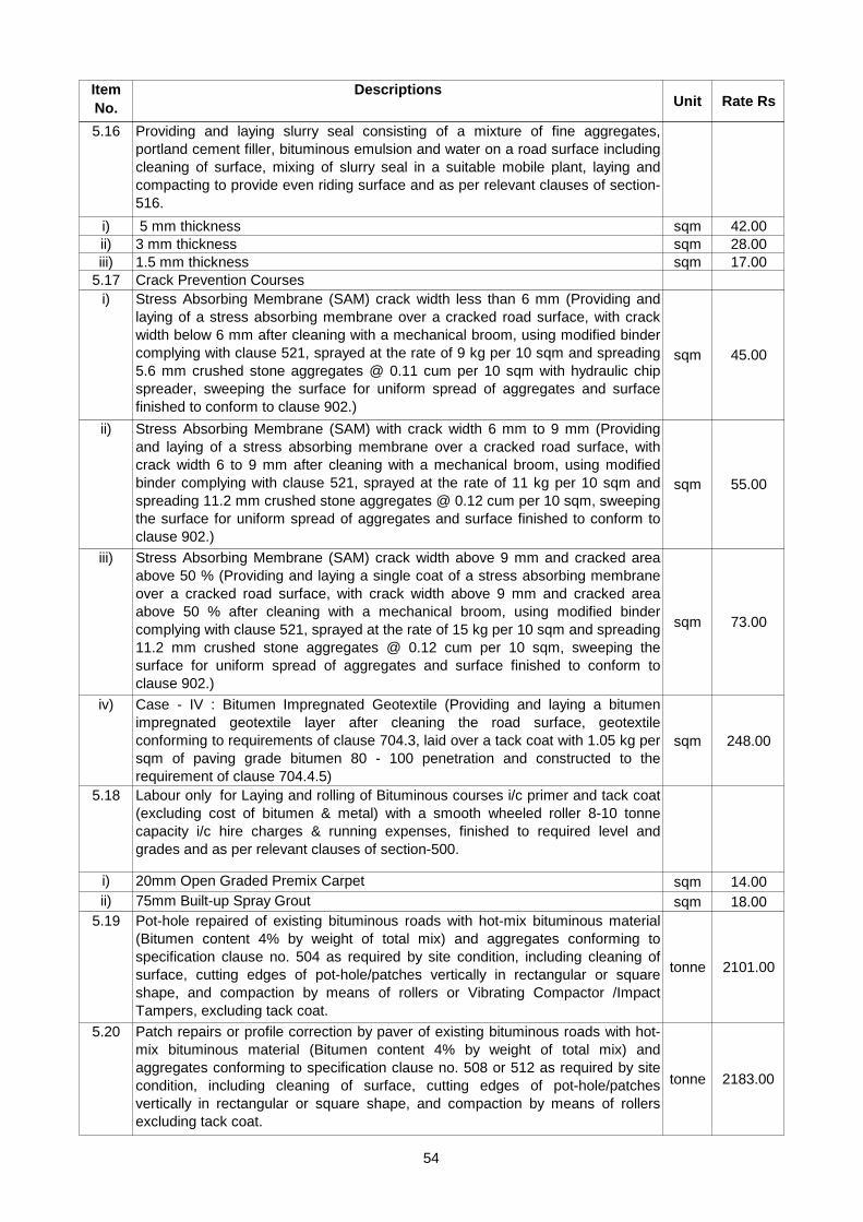
Item
No.
DescriptionsUnit Rate Rs
5.16 Providing and laying slurry seal consisting of a mixture of fine aggregates,
portland cement filler, bituminous emulsion and water on a road surface including
cleaning of surface, mixing of slurry seal in a suitable mobile plant, laying and
compacting to provide even riding surface and as per relevant clauses of section-
516.
i) 5 mm thickness sqm 42.00
ii) 3 mm thickness sqm 28.00
iii) 1.5 mm thickness sqm 17.00
5.17 Crack Prevention Courses
i) Stress Absorbing Membrane (SAM) crack width less than 6 mm (Providing and
laying of a stress absorbing membrane over a cracked road surface, with crack
width below 6 mm after cleaning with a mechanical broom, using modified binder
complying with clause 521, sprayed at the rate of 9 kg per 10 sqm and spreading
5.6 mm crushed stone aggregates @ 0.11 cum per 10 sqm with hydraulic chip
spreader, sweeping the surface for uniform spread of aggregates and surface
finished to conform to clause 902.)
sqm 45.00
ii) Stress Absorbing Membrane (SAM) with crack width 6 mm to 9 mm (Providing
and laying of a stress absorbing membrane over a cracked road surface, with
crack width 6 to 9 mm after cleaning with a mechanical broom, using modified
binder complying with clause 521, sprayed at the rate of 11 kg per 10 sqm and
spreading 11.2 mm crushed stone aggregates @ 0.12 cum per 10 sqm, sweeping
the surface for uniform spread of aggregates and surface finished to conform to
clause 902.)
sqm 55.00
iii) Stress Absorbing Membrane (SAM) crack width above 9 mm and cracked area
above 50 % (Providing and laying a single coat of a stress absorbing membrane
over a cracked road surface, with crack width above 9 mm and cracked area
above 50 % after cleaning with a mechanical broom, using modified binder
complying with clause 521, sprayed at the rate of 15 kg per 10 sqm and spreading
11.2 mm crushed stone aggregates @ 0.12 cum per 10 sqm, sweeping the
surface for uniform spread of aggregates and surface finished to conform to
clause 902.)
sqm 73.00
iv) Case - IV : Bitumen Impregnated Geotextile (Providing and laying a bitumen
impregnated geotextile layer after cleaning the road surface, geotextile
conforming to requirements of clause 704.3, laid over a tack coat with 1.05 kg per
sqm of paving grade bitumen 80 - 100 penetration and constructed to the
requirement of clause 704.4.5)
sqm 248.00
5.18 Labour only for Laying and rolling of Bituminous courses i/c primer and tack coat
(excluding cost of bitumen & metal) with a smooth wheeled roller 8-10 tonne
capacity i/c hire charges & running expenses, finished to required level and
grades and as per relevant clauses of section-500.
i) 20mm Open Graded Premix Carpet sqm 14.00
ii) 75mm Built-up Spray Grout sqm 18.00
5.19 Pot-hole repaired of existing bituminous roads with hot-mix bituminous material
(Bitumen content 4% by weight of total mix) and aggregates conforming to
specification clause no. 504 as required by site condition, including cleaning of
surface, cutting edges of pot-hole/patches vertically in rectangular or square
shape, and compaction by means of rollers or Vibrating Compactor /Impact
Tampers, excluding tack coat.
tonne 2101.00
5.20 Patch repairs or profile correction by paver of existing bituminous roads with hot-
mix bituminous material (Bitumen content 4% by weight of total mix) and
aggregates conforming to specification clause no. 508 or 512 as required by site
condition, including cleaning of surface, cutting edges of pot-hole/patches
vertically in rectangular or square shape, and compaction by means of rollers
excluding tack coat.
tonne 2183.00
54

1
1.1
1.2
1.3
1.4
1.5
1.6
1.7
1.8
(iv) The average compressive strength of each consecutive group of 5 cubes made in
accordance with MORTH Clause 903.5.1.1 shall not be less than 10 MPa at 7 days. In
addition, the minimum compressive strength of any individual cube shall not be less than
7.5 MPa at 7 days. The design mix complying with the above Clauses shall be got
approved from the Engineer and demonstrated in the trial length construction.
The batching plant shall be capable of proportioning the materials by weight. The batching
and mixing shall be carried out preferably in a forced action, central batching and mixing
plant having necessary automatic controls to ensure accurate proportioning and mixing.
Other types of mixing plant shall be permitted subject to demonstration of their satisfactory
performance during the trial length. The type and capacity of the plant shall be got
approved by the Engineer before commencement of the trial length.
The concrete shall be laid by a paver with electronic sensor unless otherwise specified.
The equipment shall be capable of laying the material in one layer in an even manner
without segregation, so that after completion the total thickness is as specified. The
paving machine shall have high amplitude tamping bars to give good initial compaction to
the sub-base. The laying of a two-lane road sub-base may preferably be done in full width
or lane by lane . Preferably the lean concrete shall be placed and compacted across the
full width of the road, by constructing it in one go or in two lanes paved forward
simultaneously.
The sub-base of lean concrete shall be overlaid with cement concrete pavement only after
7 days after sub-base construction.
The compaction shall be carried out immediately after the material is laid and levelled.
Double drum smooth-wheeled vibratory rollers of minimum 80 to 100 kN static weight are
considered to be suitable for rolling dry lean concrete.
(ii) Portland Slag Cement IS : 455
(iii) Portland Pozzolana Cement IS : 1489
(i) The mix shall be proportioned with a maximum aggregate cement ratio of 15 :1.
(iii) The minimum cement content in the lean concrete shall not be less than 150 kg/cum
of concrete. If this minimum cement content is not sufficient to produce concrete of the
specified strength, it shall be increased as necessary without additional cost compensation
to the contractor.
Proportioning of Material for the mix
The Aggregates of lean concrete shall be as per IS 383. The maximum sizes of coarse
aggregate shall be 25 mm. The fine aggregate shall consist of clean natural sand or
crushed stone sand or a combination of the two be as per IS 383.
(ii) The right amount of water for the lean concrete in the main work shall be decided so as
to ensure full compaction under rolling.
CHAPTER- R- 6
CEMENT CONCRETE PAVEMENTS
Any of the following type cement may be used with prior approval of engineer in charge:-
(i) Ordinary Portland Cement IS : 269
Notes for Specification :-
Lean concrete sub-base: -
55

1.9
1.10
1.11
2
2.1
2.2
2.3
2.4
2.5
Mild steel bars for dowels and tie bars shall conform to the requirements of IS : 432, IS
1139, IS 1786 the dowel bars shall conform to Grade S 240 and tie bar to Grade S 415 of
I.S.
(b) Curing shall be done by covering the surface by gunny bags/hessian, which shall be
kept continuously moist for 7 days by sprinkling water.
(ii) Ordinary Portland Cement, 43 Grade IS : 8112
(iii) Ordinary Portland Cement, 53 Grade IS : 12269
The unit of measurement for dry lean concrete pavement shall be the cubic meter of
concrete placed, based on the net plan areas for the specified thickness.
Measurements for payment
Rates
The rate payable for dry lean concrete sub-base include carrying out required operations
including material, equipment, mixing, transport, placing, compacting, finishing, curing,
testing etc.
Cement Concrete Pavement
Curing : As soon as the lean concrete surface is compacted, curing shall commence. One
of the following two methods shall be adopted :
(a) The initial curing shall be done by spraying with liquid curing compound. The curing
compound shall be white pigmented or transparent type with water retention index of 90
per cent when tested in accordance with BS 7542. Curing compound shall be sprayed
immediately after rolling is complete. As soon as the curing compound has lost its
tackiness, the surface shall be covered with wet hessian for three days.
The cement content shall not be less than 350 kg per cu.m. of concrete the maximum
cement content shall however not exceed 425 kg per cu.m of concrete.
Cement
Any of the following types of cement capable of achieving the design strength may be
used with prior approval of the Engineer, but the preference should be to use at least the
43 Grade or higher.
(i) Ordinary Portland Cement, 33 Grade IS : 269
Admixture : Admixture conforming of IS 6925 and IS 9103 shall be permitted to improve
workability of the concrete or extension of setting time.
(iii) Portland Pozzolana Cement IS : 1489 Part 1
Aggregates for pavement concrete shall be natural material complying with IS:383 but with
a Los Angeles Abrasion Test result not more than 35 percent. The limits of deleterious
materials shall not exceed the requirements set out in IS : 269.
Proportioning of Concrete
After approval by the Engineer of all the materials to be used in the concrete, the
Contractor shall submit the mix design based on weighed proportions of all ingredients for
the approval of the Engineer. The mix design shall be submitted at least 30 days prior to
the paving of trial length and the design shall be based on laboratory trial mixes using the
approved materials and methods as per IS:10262 (Recommended Guidelines for Mix
Design).
56

2.6
2.7 Joints: -
2.7.1
2.7.2
2.7.3
Separation Membrane : -
A separation membrane shall be used between the concrete slab and the sub-base.
Separation membrane shall be impermeable PVC sheet 125 micron thick transparent or
white in colour laid flat with minimum creases. Before placing the separation membrane,
the sub-base shall be swept clean of all the extraneous materials using air compressor.
Wherever overlap of plastic sheets is necessary, the same shall be at least 300 mm and
any damaged sheathing shall be replaced at the Contractor’s cost. The separation
membrane may be nailed to the lower layer with concrete nails.
Joints are two categories of joints for concrete pavement:
(i) Transverse joints, and
(ii) Longitudinal joints.
Joints are made at the time the pavement is constructed. Joints are formed by placing
within the concrete strips of metal or wood, or impregnated fiber, of a thickness of joints
required, embedded close under the pavement surface.
Contraction joints are also required but they are replaced by either (a) or (b). These joints
are made at right angle to the road length and extend the width of pavement.
Contraction and Expansion joints are made in concrete pavements to keep the stresses
caused by changes in the volume of the concrete due either to shrieked during hardening
and drying, or to temperature changes, and thus premed the formation of crack and
ultimate failure of the slab. Shrinkage may be caused either by the initial heat of hydration
of cement and sub sequent cooling, or by changing moisture conditions through the depth
of the slab as it dries out. Temperature changes may be seasonal or daily and there will
usually be a difference in the temperature between the top and the bottom of the slab.
Expansion joints should also be provided at intersections of pavements with structure or
other pavements. The joints filling may be assumed to be compressed up to 50 per cent of
its thickness and therefore the expansion joints gap should be twice the allowable
expansion in the concrete, the usual width is 20 to 25 mm.
Longitudinal Joints:-
These shall be of the plain butt type and shall be formed by placing the concrete against
the slab concrete earlier. The face of the slab concreted earlier, shall be painted with
bitumen before placing of fresh concrete.
Tie bar shall be used at longitudinal joints and they shall be the dimensions and at
spacings shown on the approved drawing. Tie bar shall be supported so as not to be
displaced during construction operation. Tie bars shall be bounded in the slabs across
longitudinal joints, and whilst casting the first slabs, they may be bent so that one end of
them lies along the forms. After removal of the forms, bars shall be straightened so that
they extend into the concrete placed on the other side of the joints.
(a) Expansion joints, and
(b) Contraction joints.
Transverse joints have two main clauses;
57

2.8
2.9
2.10
Concrete (i) Strength of concrete IS:516 2 cubes and 2 beams per 150 m³ or
part thereof (one for 7 day and other
for 28 days strength) or minimum 6
cubes and 6 beams per day's work
whichever is more.
(ii) Core strength on
hardened concrete
IS:516 As per the requirement of the
Engineer; only in case of doubt.
(iii) Workability of fresh
concrete-Slump Test
IS:1199 One test per each dumper load at both
Batching plant site and paving site
initially when work starts.
Subsequently sampling may be done
from alternate dumper.
(iv) Thickness
determination
From the level data of concrete
pavement surface and sub-base at
grid points of 5/6.25 m x 3.5 m.
(v) Thickness
measurement for trial
length
3 cores per trial length.
Table : Frequency of Quality Control Tests for Paving Quality Concrete
Batching and mixing of the concrete shall be done at a central batching and mixing plant
with automatic controls, located at a suitable place which takes into account sufficient
space for stockpiling of cement, aggregates and stationary water tanks, unless otherwise
specified.
Dowel Bars and Tie Bars: -
Mild steel bars for dowels and tie bars shall conform to the requirements of IS : 432, IS
1139, IS 1786 the dowel bars shall conform to Grade S 240 and tie bar to Grade S 415 of
I.S. These bar shall be provided as per approved drawing.
Batching and Mixing: -
Expansion joint ( Drawing not to be scaled)
58

(vi) Verification of level of
string line in the case of
slip form paving and steel
forms in the case of fixed
form paving
String line or steel forms shall be
checked for level at an interval of 5.0
m or 6.25 m. The level tolerance
allowed shall be 2 mm. These shall
be got approved 1-2 hours before the
commencement of the concreting
activity.
2.11
2.12
2.13
All precautions and care shall be taken to construct pavement having uniform thickness.
(For Detail Refer specification Chapter of Cement Concrete Pavement and MORTH specification
of the same)
Cement concrete pavement shall be measured as a finished work in square meters with
specified thickness. The unit for measurement for concrete pavement shall be the cubic
meter of concrete placed.
Measurement
Rates
Rate for complete item include charges of labour, material, equipment, required for
completion of items.
59

Item
No.
DescriptionsUnit Rate Rs
6.1 Construction of dry lean cement concrete Sub-base over a prepared sub-grade with
coarse and fine aggregate conforming to IS: 383, the size of coarse aggregate not
exceeding 25mm, aggregate cement ratio not to exceed 15:1, aggregate gradation
after blending to be as per table of MORTH Specifications 600-1, cement content
not to be less than 200 kg/cum, optimum moisture content to be determined during
trial length construction, concrete strength not to be less than 10 Mpa at 7 days,
mixed in a batching plant, transported to site, laid with paver with electronic
sensor/mechanical paver, compacting with 8-10 tonnes vibratory roller, finishing
and curing and as per relevant clauses of section-603.
cum 2307.00
6.1.1 Deduct for cost of cement per cum of concrete if cement is issued by agency other
then Contractor.cum 1115.00
6.2 Deduct from Item No.6.1 above if paver with Electronic sensor, vibratory roller are
not used and laying, compaction is done by any other method. . cum 161.00
6.3 Construction of dowel jointed, plain cement concrete pavement in M-40 grade
concrete over a prepared sub base with 43 or higher grade cement, maximum size
of coarse aggregate not exceeding 25 mm, mixed in a batching and mixing plant as
per approved mix design, transported to site, laid with a fixed form or slip form
paver with electronic sensor, spread, compacted and finished in a continuous
operation including provision of contraction, expansion, construction and
longitudinal joints, joint filler, separation membrane, sealant primer, joint sealant,
debonding strip, placing of dowel bar and tie rod, admixtures as approved, curing
compound, finishing to lines and grades as per approved drawings as per IRC-15
2002 and as per relevant clauses of section-602 of of MORTH specifications
complete including cost of steel in dowel bar & tie rod (32mm dowel bar @9
kg/cum of concrete & 16mm tie rod @ 1.12 kg/cum of concrete)
cum 4863.00
6.3.1 Deduct for cost of cement per cum of concrete if cement is issued by agency other
then Contractor.cum 2425.00
6.4 Deduct from Item No.6.3 above if paver with electronic sensor is not used and
laying, compaction is done by any other method (The acceptance criteria regarding
level, thickness, surface regularity, texture finish, strength of concrete and all other
quality control measures shall be the same as in case of machine laid work.)
cum 340.00
6.5 Construction of dowel jointed, plain cement concrete pavement in M-30 grade
concrete over a prepared sub base with 43 grade cement maximum size of coarse
aggregate not exceeding 25 mm, mixed in a batching and mixing plant as per
approved mix design, transported to site, laid with a fixed form or slip form paver
with spreading the concrete by shovels, rakes compacted using needle, screed and
plate vibrator and finished in a continuous operation including provision of
contraction, expansion, and longitudinal joints, joint filler, separation membrane,
sealant primer, joint sealant, debonding strip, placing of dowel bar,tie rod
admixtures as approved, curing compound, finishing to lines and grades as per
approved drawings as per IRC-15 2002 and as per relevant clauses of section-602
of specifications complete including cost of steel in dowel ber & tie rod (32mm
dowel bar @9 kg/cum of concrete & 16mm tie rod @ 1.12 kg/cum of concrete)
cum 4779.00
6.5.1 Deduct for cost of cement per cum of concrete if cement is issued by agency other
then Contractor.cum 2342.00
6.5.2 Labour rate with required machines for complition of item no. 6.5. cum 195.00
CEMENT CONCRETE PAVEMENTS
CHAPTER-6
60

Item
No.
DescriptionsUnit Rate Rs
6.6 Providing and laying stone-set pavement including preparation of 100mm thick
compacted Granular Sub-base as per Clause of section 400 and base 75mm thick
compacted water bound macadam grading 2 as per Clause 405.3. The stone set
pavement shall consist of 150mm thick hammer dressed stones in the herring one
or stretched bond pattern, on the bedding sand of 40mm. Over the WBM base
bounded by edge stone using suitable compacting device. The gaps are to be filled
with sand stone dust.
Sqm 311.00
6.7 Construction of Base/sub-base using cement, sand, fly ash and coarse aggregates
proportioned as per table 4 of IRC: 74/1979 and with water content ratio, slump and
compressive strength as defined in the said table, mix prepared in a batching and
mixing plant, transported to site, laid with paver with electronic sensor and
compacted with a vibratory roller 8-10 tonnes capacity within the time limit laid
down vide clause 7.6.3 of IRC: 74-1979, construction joints properly formed at the
end of day's work, cured for 14 days, all as specified in IRC: 74-1979 and as per
approved plans and as per relevant clauses of section-600.
cum 1923.00
6.7.1 Deduct for cost of cement per cum of concrete if cement is issued by agency other
then Contractor. cum 836.00
6.8 Deduct from Item No.6.7 above if paver with electronic sensor, vibratory roller are
not used and laying, compaction is done by any other method. . cum 135.00
6.9 Providing and laying reinforced cement concrete pipe 300mm dia NP-4 for service
ducts.
Providing and laying of a reinforced cement concrete pipe duct, 300 mm dia,
across the road (new construction), extending from drain to drain in cuts and toe of
slope to toe of slope in fills, constructing head walls in cement mortar 1:3 at both
ends, providing a minimum fill of granular material over top and sides of RCC pipe
as per IRC:98-1997, bedded on a 0.3 m thick layer of granular material free of rock
pieces, outer to outer distance of pipe at least half dia of pipe subject to minimum
450 mm in case of double and triple row ducts, joints to be made leak proof, invert
level of duct to be above higher than ground level to prevent entry of water and dirt,
all as per IRC: 98 - 1997 and approved drawings
(i) Single row for one utility service meter 1201.00
(ii) Double row for one utility service meter 2230.00
(iii) Triple row for one utility service meter 3266.00
6.10 Providing and laying Cement Concrete grade M-10 Nominal mix with 20 mm
graded crushed stone aggregate, laid with a fixed form or slip form paver with
spreading the concrete by shovels mixing shall be in mechanical mixer, compacting
by use of pin plate and screed vibrators including form work by strong steel girders
fixed by spikes.
Cum 2950.00
6.10.1 Deduct for cost of cement per cum of concrete if cement is issued by agency other
then Contractor. Cum 1227.00
61

Item
No.
DescriptionsUnit Rate Rs
6.11 Providing and laying Cement Concrete grade M-20 (Nominal mix 1:1.5:3) with 20
mm graded crushed stone aggregate, mixing shall be in mechanical mixer, laying
with paver compacting by use of pin, plate and screed vibrators including form work
by strong steel girders fixed by spikes, separation membrane 125 micron thick, i/c
cutting of joints @ 4 to 5 m interval & filling it with hot applied bituminous sealant
without dowel bars.
Cum 4044.00
6.11.1 Deduct for cost of cement per cum of concrete if cement is issued by agency other
then Contractor. Cum 2268.00
62

CHAPTER- R- 7
GEOSYNTHETICS AND REINFORCED
1 Geosynthetics is a general classification for all synthetic materials used in geotechnical
engineering application. It includes geotextiles, geogrids, geonets, geomembranes and
geocomposites.
2 (i) The paving fabric will be a nonwoven heat set material consisting of at least 85 per
cent by weight polyolefins, polyesters or polyamides.
(ii) The paving fabric shall be resistant to chemical attack, rot and mildew and shall
have no tears or defects which will adversely alter its physical properties.
(iii) The fabric shall be specifically designed for pavement applications and be heart
bonded only on one side to reduce bleed-through of tack coat during installation.
(iv) The fabric shall meet the physical requirements.
(v) Heavy duty paving fabrics should be used in areas experiencing unusually high
impact forces or heavy loads such as airport runways and taxiways.
3 Tack coat shall be spread by means of a calibrated distributor spray bar. Hand
spraying and brush application may be used in locations of fabric overlap.
4 Paving fabric placement
(i) The paving fabric shall be placed onto the tack coat using mechnical or manual
laydown equipment capable of providing a smooth installation with a minimum amount
of wrinkling or folding.
(ii) The paving fabric shall be placed prior to the tack coat cooling and losing tackiness.
(iii) Paving fabric shall not be installed in areas where the overlay asphalt tapers to a
thickness of less 40 mm.
5 (i) In Protection work mattresses constructed with Geogrids or Geonets shall be used
for thickness of 300 mm or above.
(ii) Mattresses constructed with Geogrids or Geonets shall be used for thickness of 30
mm or above as shown in the drawings. While adopting a particular size for gabions or
mattresses, width of the roll of geogrid/geonet may be kept in view to minimize
wastage of the geosynthetic in cutting off pieces. The mesh opening may vary
depending on functional requirement but shall have aperture between 35 mm and 100
mm. The mesh/net shall have following characteristics:
Aperture: - Rectangular, square or oval shaped (and not in diamond, round or
polygonal shape).
Colour: - Black
Mechanical Properties :- Peak strength not less than 10 kN/m at maximum
longation of 15 per cent. Not more than 5 per cent elongation at half peak load.
Stands/Fabric: - Integral joints with junction strength of 100 per cent of plain.
Notes for Specification :-
63

Form: - Strands as measured by GRI-GG3 standards. Material shall have ISO 9002
certification
Life: - At least 8 years in case of continuous exposure and 5 years for buried
applications (defined as capable of retaining at least 75 per cent of its original strength
after the life span stated).
6 Measurement
(i) The fabric of geotextile/ geocomposite shall be measured in sq. meters of plan area
of actual use.
9 Rates
The cost of Geosynthetic material for fabrication of Gabions/Mattresses shall be all
inclusive of supply, transportation and storage
The contract rate per cubic meter of crate fill shall consist of cost of boulders and their
transportation.
The contract rate for excavation including backfilling of trenches, seating trench upto
15 cm (included in rate), shall include cost of all labour, tools and plant for completion
of the work to these Specifications.
The cost of making a crate shall include preparation of box of geogrid/geonet,
tensioning and staking arrangements, tying, internal crossbraids, etc., for forming of
the crates in an engineered manner and filling the crate by laying boulders. The cost
shall include transportation of material from store to site.
10 Note For Item no 7.3
Note 1.The specification and construction details to be adopted shall be as per section 3100
of MoRTH Specification.
2.Drainage arrangement shall be made as per approved design and drawings.
3.The quantity of filler media shall be calculated as per approved design and
specifications and shall be priced separately. The rate for same to be adopted from
chapter 15.
4.Excavation for foundation including foundation concrete and groove in the foundation
for seating of bottom most facia panel and capping beam to be calculated as per
design and priced separately. The rates for excavation and foundation concrete shall
be taken from the chapter 12 & 13 in bridge section.
5.The earth fill to be retained is not included in this analysis. The same is to be worked
out and provided separately complete as per clause 305.
6.For compaction of Earthwork, attention is invited to clause 3105.5 of MoRTH
Specification.
7.Length of reinforcing strips will vary with the height of wall and will be as per
approved design and drawings.
8.The type of reinforcing elements to be adopted shall be as per approved design and
specifications.
9.The market rate for supply of reinforcing elements and their accessories are to be
ascertained from reputed firms in the field of earth reinforcement.
10.The earth fill material shall be clean, free draining, granular with high friction and
low cohesion, non-corrosive, coarse grained with not 10 per cent of particles passing
75 micron sieve, free of any deleterious matter, chlorides, salts, acids, alkalies, mineral
oil, fungus and microbes and shall be of specified PH value.
64

11.Capping beam is to be priced separately as per approved design. The rate for
cement concrete shall be taken from the chapter of sub-structure in bridge section.
12.The cost of reinforced earth retaining wall shall include following:
(i) Excavation for foundation including backfilling.
(ii) Foundation concrete as per approved design.
(iii) Cost of facial panels and their erection .
(iv) Cost of reinforcing elements including their fixing and joining with the facial panels.
(v) Drainage arrangement including filter media as per approved design and drawings.
13. The compacted earth filling to be retained shall form part of embankment.
For Detail Refer specification chapter of Geosynthetics & Reinforced and MORTH
Specification of the same
65

Item
No.
DescriptionsUnit Rate Rs
7.1 Laying Paving Fabric Beneath a Pavement Overlay (Providing and
laying paving fabric with physical requirements as per table 704-2 over a
tack coat of paving grade Bitumen 80-100 penetration, laid at the rate of
1 kg per sqm over thoroughly cleaned and repaired surface to provide a
water resistant membrane and crack retarding layer. Paving fabric to be
free of wrinkling and folding and to be laid before cooling of tack coat,
brooming and rolling of surface with pneumatic roller to maximise paving
fabric contact with pavement surface as per relevant clauses of section-
700 of specifications.
sqm 130.00
7.2 Laying Boulder Apron in Crates of Synthetic Geogrids (Providing,
preparing and laying of geogrid crated apron 1 m x 5 m, 600 mm thick
including excavation and backfilling with baffles at 1 meter interval,
made with geogrids having characteristics as per clause 704.2, joining
sides with connectors/ring staples, top corners to be tie tensioned,
placing of suitable cross interval ties in layers of 300 mm connecting
opposite side with lateral braces and tied with polymer braids to avoid
bulging, constructed as per clause 704.3. filled with stone with minimum
size of 200 mm and specific gravity not less than 2.65, packed with
stone spalls, keyed to the foundation recess in case of sloping ground
and laid over a layer of geotextile to prevent migration of fines as per
approved design as per relevant clauses of section-700 & 2500 of
specifications.
cum 2487.00
7.3 Construction of Reinforced Earth Retaining Wall including excavation for
foundation, foundation concrete and cement concrete grooved sealing in
foundation for facing elements and placement, assembling, joining and
laying of reinforcing element complete. The above item shall be payable
only after back filling behind the wall is completed by granular material
duly watered, rolled and completed. (Back filling behind the facing
element shall be paid separately as per Chapter-R-3 item No.3.11)
(i) Assembling, joining and laying of reinforcing elements.
A With reinforcing element of steel / Aluminium strips / polymeric strips.
Type 1 1.Galvanised carbon steel strips meter 358.00
Type 2 2.Copper Strips meter 320.00
Type 3 3.Aluminium Strips meter 320.00
Type 4 4.Stainless steel strips meter 320.00
Type 5 5.Glass reinforced polymer/fibre reinforced polymer/polymeric strips meter 396.00
B With reinforcing elements of synthetic geogrids sqm 195.00
(ii) Facing elements of RCC sqm 672.00
GEOSYNTHETICS AND REINFORCED EARTH
CHAPTER-7
66

CHAPTER- R- 8
TRAFFIC SIGNS, MARKINGS & OTHER ROAD APPURTENANCES
1 (i) The colour, configuration, size, location and dimensions of different road signs shall be in
conformity with the Code of Practice for Road Signs IRC: 67.
(ii) The language of inscription and font for informatory signs shall also be in conformity with the
Code of Practice for Road Signs IRC: 67.
2 The signs shall be either reflectorised or non-reflectorised as directed by the engineer in charge.
3 The sign board shall be so constructed as to hold these in a proper and permanent position
against the normal storm wind loads. Sign shall be fixed over mild steel sheeting and fixed to MS
post by welding and to the RC or GI posts by bolts and washers properly.
4 Normally signs with an area upto 0.90 sqm can be mounted on a single post and for greater area
two or more supports shall be provided.
5 Concrete for footings shall be of minimum M15 grade. & reinforcement steel shall be as per
IS:1786. bolts, nuts and washers shall be as per IS:1367. Field welding shall not be permitted.
Plate and support sections for sign posts shall conform IS : 226 and IS : 2062.
6 Cautionary and mandatory signs generally fabricated through process of screen printing. In
regard to informatory signs either the message could be printed over the reflective or cut letters
of non-reflective black sheeting used for the purpose which must be bonded well on the base
sheeting.
7 Support and component of signs except the reflectorised portion and GI posts, shall be
thoroughly descaled, cleaned, primed and painted with two coats of epoxy paint. The portion of
mild steel post below ground should be painted with three coats of red lead paint.
8 The messages and borders shall either be screen-printed or of cut-outs. Cut-outs messages and
borders, wherever used, shall be made out of retro-reflective sheeting except those in black shall
be of non-reflective sheeting.
9 Overhead signs shall be design to withstand a wind loading of 150 kg/sqm normal to the face of
sign and 30 kg/sqm transvers to the face of the sign in addition to the dead load of the structure
walkway loading of 250 kg concentrated live load shall also be considered for the design of the
overhead sign structure.
10 In General, overhead signs shall provide a vertical clearance of not less than 5.5 m over the
entire width of the pavement and shoulders .
11 The minimum lateral clearance outside the usable roadway shoulder for expressway signs
mounted at the road side or for overhead sign supports either to the right or left side of the
roadway shall be 1.80 m.
12 For outside of an unmountable kerb the minimum lateral clearance shall be of 1.80 m.
13 In no case should there be more than three signs displayed at any one location, including
regulatory or warning signs, either on the overhead structure or on its support.
14 Layout, colour of road markings shall be in accordance with the code of practice for Road
markings with paints, IRC : 35.
Notes for Specification :-
67

15 Marking shall be done by machine are manually.
16 Thermoplastic material shall be applied hot either by screeding or extrusion process & the
pavement temperature shall not be less than 100
C during application of thermoplastic material.
Thermoplastic paint shall be applied in intermittent or continuous lines of uniform thickness of at
least 2.5mm unless specified otherwise. Where arrows or letters are to be provided,
thermoplastic compound may be hand-sprayed.
17 The boundary stone shall be as per design & specification in IRC 25 the arrangement of letters
and script shall be as per IRC : 26.
18 The fencing barbed wire shall be galvanised iron and shall conform to IS : 278 and M.S. posts
shall conform to IS : 226.
19 The railing shall be of tubular steel in conformance to IS : 1239.
20 The concrete barriers shall be constructed with M-20 grade concrete and with Higher Yield
Strength.
21 Measurement
(i) The measurement of standard cautionary, mandatory and information signs shall be in
numbers of different types of signs supplied and fixed, while for direction and place identification
signs, these shall be measured by area in square meters.
(ii) Aluminium or steel overhead sign structure will be measured for payment by the specific unit
(each) complete in place or for each component of the overhead sign structure as indicated in
the bill of quantities and the detailed drawings(s).
(iii) Flat sheet aluminium signs with retro-reflective sheeting thereon shall be measured for
payment by the square meter for each thickness, complete in place.
(iv) The painted markings shall be measured in sq. meters of actual area marked (excluding the
gaps, if any).
(v) In respect of markings like directional arrows and lettering, etc., the measurement shall be by
numbers.
(vi) All barriers will be measured by linear meters of completed and accepted length in place,
corresponding end to end along the face of concrete barriers including approach and departure
ends.
(vii) Metal beam railing barriers will be measured by linear meter of completed length as per
plans and accepted in place. Terminals/anchors of various types shall be paid for by numbers.
(viii) No measurement for payment shall be made for projections or anchors beyond the end
posts except as noted above. Furnishing and placing anchor bolts and/or devices for guard rail
posts on bridges shall be considered incidental to the construction and the costs there or shall
be included in the price for other items of construction.
(ix) No measurement for payment will be made for excavation or backfilling performed in
connection with this construction.
9 Rates
Rate for complete item include charges of labour, material, equipment, required for completion
of items.
For Detail Refer specification Chapter of Traffic Signs, Markings and
MORTH Specification of the same
68
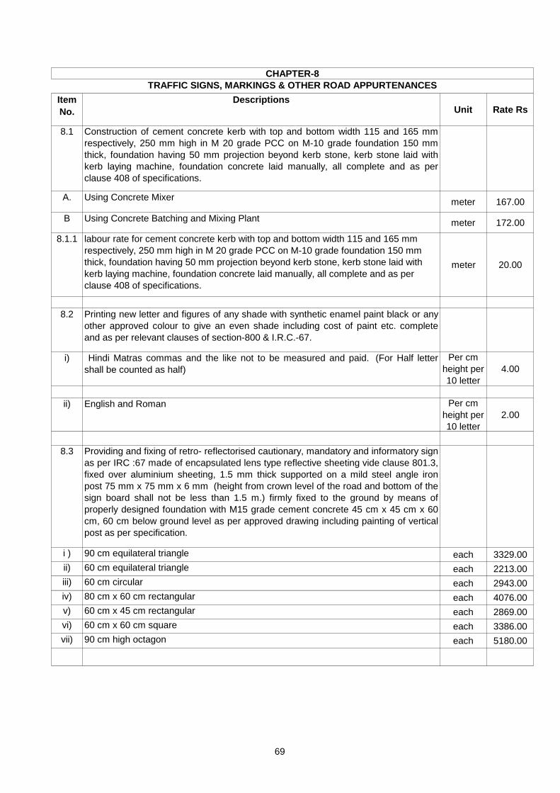
Item
No.
DescriptionsUnit Rate Rs
8.1 Construction of cement concrete kerb with top and bottom width 115 and 165 mm
respectively, 250 mm high in M 20 grade PCC on M-10 grade foundation 150 mm
thick, foundation having 50 mm projection beyond kerb stone, kerb stone laid with
kerb laying machine, foundation concrete laid manually, all complete and as per
clause 408 of specifications.
A. Using Concrete Mixermeter 167.00
B Using Concrete Batching and Mixing Plantmeter 172.00
8.1.1 labour rate for cement concrete kerb with top and bottom width 115 and 165 mm
respectively, 250 mm high in M 20 grade PCC on M-10 grade foundation 150 mm
thick, foundation having 50 mm projection beyond kerb stone, kerb stone laid with
kerb laying machine, foundation concrete laid manually, all complete and as per
clause 408 of specifications.
meter 20.00
8.2 Printing new letter and figures of any shade with synthetic enamel paint black or any
other approved colour to give an even shade including cost of paint etc. complete
and as per relevant clauses of section-800 & I.R.C.-67.
i) Hindi Matras commas and the like not to be measured and paid. (For Half letter
shall be counted as half)
Per cm
height per
10 letter
4.00
ii) English and Roman Per cm
height per
10 letter
2.00
8.3 Providing and fixing of retro- reflectorised cautionary, mandatory and informatory sign
as per IRC :67 made of encapsulated lens type reflective sheeting vide clause 801.3,
fixed over aluminium sheeting, 1.5 mm thick supported on a mild steel angle iron
post 75 mm x 75 mm x 6 mm (height from crown level of the road and bottom of the
sign board shall not be less than 1.5 m.) firmly fixed to the ground by means of
properly designed foundation with M15 grade cement concrete 45 cm x 45 cm x 60
cm, 60 cm below ground level as per approved drawing including painting of vertical
post as per specification.
i ) 90 cm equilateral triangle each 3329.00
ii) 60 cm equilateral triangle each 2213.00
iii) 60 cm circular each 2943.00
iv) 80 cm x 60 cm rectangular each 4076.00
v) 60 cm x 45 cm rectangular each 2869.00
vi) 60 cm x 60 cm square each 3386.00
vii) 90 cm high octagon each 5180.00
CHAPTER-8
TRAFFIC SIGNS, MARKINGS & OTHER ROAD APPURTENANCES
69

Item
No.
DescriptionsUnit Rate Rs
8.4 Direction and Place Identification signs upto 0.9 sqm size board. (Providing and
erecting direction and place identification retro-reflectorised sign asper IRC:67 made
of encapsulated lens type reflective sheeting vide clause 801.3, fixed over aluminium
sheeting, 2 mm thick with area not exceeding 0.9 sqm supported on a mild steel
single angle iron post 75x75x6 mm (height from crown level of the road and bottom
of the sign board shall not be less than 1.5 m.) firmly fixed to the ground by means of
properly designed foundation with M15 grade cement concrete 45 x 45 x 60 cm, 60
cm below ground level as per approved drawing including painting of vertical post as
per specification.
sqm 7207.00
8.5 Direction and Place Identification signs with size more than 0.9 sqm size board.
(Providing and erecting direction and place identification retro- reflectorised sign
asper IRC :67 made of encapsulated lens type reflective sheeting vide clause 801.3,
fixed over aluminium sheeting, 2 mm thick with area exceeding 0.9 sqm supported
on a mild steel angle iron post 75 mm x 75 mm x 6 mm (height from crown level of
the road and bottom of the sign board shall not be less than 1.5 m.) , 2 Nos. firmly
fixed to the ground by means of properly designed foundation with M 15 grade
cement concrete45 cm x 45 cm x 60 cm, 60 cm below ground level as per approved
drawing including painting of vertical post as per specification.
sqm 12470.00
8.6 Painting two coats after filling the surface with synthetic enamel paint in all shades on
new plastered concrete surfaces and as per relevant clauses of section-800 & I.R.C.-
67 including cost of paint etc. complete. sqm 441.00
8.6.1 Labour rate excluding the cost of material for Item No.- 8.6 sqm 13.00
8.7 Providing and applying two coats of ready mix paint of approved brand on steel
surface after through cleaning of surface to give an even shade as per relevant
clauses of section-800 & I.R.C.- 67 including cost of paint etc. complete.sqm 39.00
8.8 Painting lines, dashes, arrows etc on roads in two coats on new work with ready
mixed road marking paint conforming to IS:164 on bituminous surface, including
cleaning the surface of all dirt, dust and other foreign matter, demarcation at site and
traffic control as per relevant clauses of section-800 & I.R.C.-67 including cost of
paint etc. complete.
i) Over 10 cm in width sqm 61.00
8.8.1 Labour rate excluding the cost of material for Item No.- 8.8 (i) sqm 35.00
ii) Up to 10 cm in width sqm 54.00
8.8.2 Labour rate excluding the cost of material for Item No.- 8.8 (ii) sqm 28.00
8.9 Painting Lines, Dashes, Arrows etc on Roads in Two Coats on Old Work (Painting
lines, dashes, arrows etc on roads in two coats on old work with ready mixed road
marking paint confirming to IS: 164 on bituminous surface, including cleaning the
surface of all dirt, dust and other foreign matter, demarcation at site and traffic
control as per relevant clauses of section-800 of specifications.
i) Over 10 cm in width sqm 41.00
ii) Up to 10 cm in width sqm 54.00
8.9.1 Labour rate excluding the cost of material for Item No.- 8.9 (i) sqm 26.00
70

Item
No.
DescriptionsUnit Rate Rs
8.10 Road Marking with Hot Applied Thermoplastic Compound with Reflectorising Glass
Beads on Bituminous Surface (Providing and laying of hot applied thermoplastic
compound 2.5 mm thick including reflectorising glass beads @ 250 gms per sqm
area, thickness of 2.5 mm is exclusive of surface applied glass beads as per IRC:35
.The finished surface to be level, uniform and free from streaks and holes and as per
relevant clauses of section-800.
sqm 897.00
8.11 Providing reinforced cement concrete M15grade kilometer stone of standard design
as per IRC:8-1980, fixing in position including painting and printing etc as per
relevant clauses of section-800 of specifications.
i) 5th kilometer stone (precast) each 2775.00
8.11.1 Labour for fixing painting and printing of reinforced cement concrete M15 grade 5th
k.m stone (precast) as per item 8.11.(i) each 301.00
ii) Ordinary Kilometer stone (Precast) each 1559.00
8.11.2 Labour for fixing painting and printing of reinforced cement concrete M15 grade 5th
k.m stone (precast) as per item 8.11.(ii) each 141.00
iii) Hectometer stone (Precast) each 385.00
8.11.3 Labour for fixing painting and printing of reinforced cement concrete M15 grade 5th
k.m stone (precast) as per item No.- 8.11 (iii) each 49.00
8.12 Road Delineators (Supplying and installation of delineators (road way indicators,
hazard markers, object markers), 80-100 cm high above ground level, painted black
and white in 15 cm wide stripes, fitted with 80 x 100 mm rectangular or 75 mm dia
circular reflectorised panels at the top, buried or pressed into the ground and
confirming toIRC-79 and the drawings as per relevant clauses of section-800 of
specifications.
each 290.00
8.13 Providing reinforced cement concrete M15 grade boundary pillars of standard design
as per IRC:25-1967, fixed in position including finishing and lettering but excluding
painting)each 406.00
8.13.1 Labour rate for fixing of boundary pillar with lettering as per item No.- 8.13 each 54.00
8.14 G.I Barbed wire Fencing 1.2 meter high (Providing and fixing 1.2 meters high GI
barbed wire fencing with 1.8 m angle iron posts 40 mm x 40 mm x 6 mm placed
every 3 meters center to center founded in M15 grade cement concrete, 0.6 meter
below ground level, every 15th post, last but one end post and corner post shall be
strutted on both sides and end post on one side only and provided with 9 horizontal
lines and 2 diagonals interwoven with horizontal wires, fixed with GI staples, turn
buckles etc complete as per relevant clauses of section-800 of specifications.
meter 203.00
8.14.1 Labour rate only for fixing barbed wire fencing as per item No.- 8.14 meter 13.00
71

Item
No.
DescriptionsUnit Rate Rs
8.15 G.I Barbed wire Fencing 1.8 meter high Providing and fixing 1.8 meters high GI
barbed wire fencing with 2.4 m angle iron posts 50 mm x 50 mm x 6 mm placed
every 3 meters center to center founded in M15 grade cement concrete, 0.6 meter
below ground level, every 15th post, last but one end post and corner post shall be
strutted on both sides and end post on one side only and provided with 12 horizontal
lines and 2 diagonals interwoven with horizontal wires, fixed with GI staples, turn
buckles etc complete as per clause 807 of MORTH specifications.
meter 334.00
8.15.1 Labour rate only for fixing barbed wire fencing as per item No.- 8.15 meter 16.00
8.16 Tubular Steel Railing on Medium Weight steel channel ( ISMC series) 100 mm x 50
mm (Providing, fixing and erecting 50 mm dia GI pipe (medium class) railing in 3
rows duly painted on medium weight steel channels (ISMC series) 100 mm x 50 mm,
1.2 meters high above ground, 2 m centre to centre, complete as per approved
drawings as per relevant clauses of section-800 of specifications.
meter 1435.00
8.17 Tubular Steel Railing on Precast RCC posts, 1.2 m high above ground level
(Providing, fixing and erecting 50 mm dia GI pipe (medium class) railing in 3 rows on
precast M20 grade RCC vertical posts1.8 meters high (1.2 m above GL) with 3 holes
50 mm dia for pipe, fixed 2 meters centre to, complete as per approved drawing as
per relevant clauses of section-800 of specifications.
meter 1095.00
8.17.1 Labour rate for erecting 15 mm dia GI pipe railing in 3 rows on precast m20 grade
RCC vertical posts Item No.- 8.17meter 6.00
8.18 Reinforced Cement Concrete Crash Barrier (Provision of an Reinforced cement
concrete crash barrier at the edges of the road, approaches to bridge structures and
medians, constructed with M-20 grade concrete with HYSD reinforcement
conforming to IRC:21 and dowel bars 25 mm dia, 450 mm long at expansion joints
filled with pre-moulded asphalt filler board, keyed to the structure on which it is built
and installed as per design given in the enclosure to MOST circular No. RW/NH -
33022/1/94-DO III dated 24 June 1994 as per dimensions in the approved drawing
and at locations directed by the Engineer, all as specified as per relevant clauses of
section-800 of specifications.
i) M 20 grade concrete meter 2455.00
8.19 Metal Beam Crash Barrier
a) Type - A, "W" : Metal Beam Crash Barrier (Providing and erecting a "W" metal beam
crash barrier comprising of 3 mm thick corrugated sheet metal beam rail, 70 cm
above road/ground level, fixed on ISMC series channel vertical post, 150 x 75 x 5
mm spaced 2 m centre to centre, 1.8 m high, 1.1 m below ground/road level, all steel
parts and fitments to be galvanised by hot dip process, all fittings to conform to
IS:1367 and IS:1364, metal beam rail to be fixed on the vertical post with a spacer of
channel section 150 x 75 x 5 mm, 330 mm long complete as per clause 810 of
specifications
meter 4029.00
72

Item
No.
DescriptionsUnit Rate Rs
b) Type - B, "THRIE" : Metal Beam Crash Barrier (Providing and erecting a "Thrie"
metal beam crash barrier comprising of 3 mm thick corrugated sheet metal beam
rail, 85 cm above road/ground level, fixed on ISMC series channel vertical post, 150
x 75 x 5 mm spaced 2 m centre to centre, 2 m high with 1.15 m below ground level,
all steel parts and fitments to be galvanised by hot dip process, all fittings to conform
to IS:1367 and IS:1364, metal beam rail to be fixed on the vertical post with a space
of channel section 150 x 75 x 5 mm, 546 mm long complete as per clause 810 of
specifications.
meter 5800.00
8.20 Road Markers/Road Stud with Lense Reflector (Providing and fixing of road stud
100x 100 mm, dia cast in aluminium, resistant to corrosive effect of salt and grit,
fitted with lense reflectors, installed in concrete or asphaltic surface by drilling hole 30
mm upto a depth of 60 mm and bedded in a suitable bituminous grout or epoxy
mortar, all as per BS 873 part 4:1973)
each 687.00
8.20.1 Labour rate for fixing road stud as per Item No.- 8.20 each 3.00
8.21 Traffic Cone (Provision of red fluorescent with white reflective sleeve traffic cone
made of low density polyethylene (LDPE) material with a square base of 390 x 390 x
35 mm and a height of 770 mm, 4 kg in weight, placed at 1.5 m interval, all as per BS
873)
each 186.00
8.22 Portable Barricade in Construction Zone (Installation of a steel portable barricade
with horizontal rail 300 mm wide, 2.5 m in length fitted on a 'A' frame made with 45 x
45 x 5 mm angle iron section, 1.5 m in height, horizontal rail painted (2 coats) with
yellow and white stripes, 150 mm in width at an angle of 45 Degrees, 'A' frame
painted with 2 coats of yellow paint, complete as per IRC:SP:55-2001 )
each 2053.00
8.23 Permanent Type Barricade in Construction Zone
a) With Steel Components (Construction of a permanent type barricade made of steel
components, 1.5 m high from road level, fitted with 3 horizontal rails 200 mm wide
and 4 m long on 50 x 50 x 5 mm angle iron vertical support, painted with yellow and
white strips, 150 mm in width at an angle of 450, complete as per IRC:SP:55-2001)
each 3306.00
8.23.1
(a)
Labour rate for Construction of a permanent type barricade made of steel
components, 1.5 m high from road level, fitted with 3 horizontal rails 200 mm wide
and 4 m long on 50 x 50 x 5 mm angle iron vertical support, painted with yellow and
white strips, 150 mm in width at an angle of 450, complete as per IRC:SP:55-
2001.including charges for welding drilling etc.
each 264.00
b) With Bricks (Construction of a permanent type barricade made with brick work in
mud mortar, 1.5 m high, 4 m long, 600 mm thick, plastered with cement mortar
1:6, painted with yellow and white strips)each 7661.00
8.23.2 Labour rate for Construction of a permanent type barricade made with brick work in
mud mortar, 1.5 m high, 4 m long, 600 mm thick, plastered with cement mortar
1:6, painted with yellow and white strips.each 1029.00
8.24 Drum Delineator in Construction Zone (Provision of metal drum/empty bitumen drum
delineator, 300 mm in diameter, 800 mm high, filled with earth for stability, painted
in circumferential strips of alternate black and white 100 mm wide fitted with
reflectors 3 Nos of 7.5 cm dia, all as per IRC:SP:55-2001)
each 358.00
73

Item
No.
DescriptionsUnit Rate Rs
9.1 Supply of mineral aggregate like broken stone/crushed stone (crushed in mechanical
crusher) as per clause 514 at road site including all lead and stacking etc. complete.
i) 75mm standard size broken stone cum 361.00
ii) 63mm standard size broken stone cum 361.00
iii) 45mm standard size broken stone cum 361.00
iv) 40mm standard size crushed stone cum 547.00
v) 26.5mm standard size crushed stone cum 594.00
vi) 22.4mm standard size crushed stone cum 607.00
vii) 13.2mm standard size crushed stone cum 689.00
viii) 11.2mm standard size crushed stone cum 524.00
ix) 6.7mm standard size crushed stone cum 472.00
9.2 Supply as per clause 514 including all lead and stacking etc. complete.
i) Crusher stone dust (clause 507.2.3) cum 198.00
ii) Sand/Shingle/Kanker/Laterite cum 239.00
iii) Moorum with CBR not less than 20 and P.I. Not exceeding 6. cum 208.00
9.3 Supply of binding material at road site having P.I. Value less than 6 confirming to
clause 404.2.7. cum 208.00
Note : In case of suitable binding material having a P.I. Value of less than 6 is not available
within reasonable distances. The contractor (at his own cost) may add an admixture
of lime to lower down the P.I. to bring it within the above range. A factor of safety of 2
should be applied to the results of laboratory to decide the percentage of lime to be
added.
CHAPTER-9
SUPPLY OF MATERIAL
74

CHAPTER- R- 10
MAINTENANCE OF ROADS
1 For repair of rain cuts fresh material (as per Sub-section 301) shall be placed in layers not
exceeding 250 mm loose thickness and compacted so as to match with the benching at a
moisture content close to the optimum. The area affected by the rain cuts shall be cleared of
all loose soil and benched before laying of fresh material. The width shall be 300 mm and
height shall be 150 to 300 mm.
2 The work of maintenance of earthen shoulder shall include making up the irregularities/loss of
material on shoulder to the design level by adding fresh approved soil and compacting it with
appropriate equipments or to strip excess soil from the shoulder surface as per the
requirements of this specification.
3 The material used in meintenance operation shall be of a standard not less than those
specified for the original construction.
4 Pot-hole and patch repair
(i) Each pot-hole and patch repair area shall be inspected and all loose material removed.
(ii) In the preparation of the area for pot hole and patch repair the area for repair shall be
cut/trimmed either with jack hammers or with hand tools suitable for the purpose, such that
the defective material responsible for the failure is all removed and such that the excavation is
of a regular shape. The edges of the excavation shall be cut vertically. The area shall be
completely cleaned by any sutable method.
(iii) Layers below the level of the bituminous connection shall be replaced and compected.
(iv) The area for bituminous construction shall be tacked or primed with cutback or emulsion
depending upon whether the lower area is bituminous or granular in nature. The side,
however, are to be painted with hot tack coat material using the brush.
5 (i) The mixture to be used in bituminous patching shall be either a hot mix or a cold mix.
(ii) The bituminous mixture shall be placed in layers of thickness not more than 100 mm
(loose) and shall be compacted in layers with roller/plate compactor/hand roller/rammer to the
compaction as per specification.
(iii) While placing the final layer, the mix shall be spread slightly proud of the surface so that
after rolling, the surface shall be flush with the adjoining surface.
(iv) If the area is large, the spreading and levelling shall be done using hand shovels and
wooden straight edges.
(v) During the process of compaction, the surface levels shall be checked using a 3m straight
edge.
6 Crack selling
(i) Fog seal for use in maintenance work shall conform to the requirements of MORTH 518.
(ii) Fog seal shall be used for sealing fine hair-cracks with less than 3 mm width.
(iii) The area to be treated with fog seal shall be thoroughly cleaned using compressed air,
scrubbers, etc.
Notes for Specification :-
75

(iv) The cracks shall be cleaned with a compressed air jet to remove all dirt, dust, etc.
(v) The fog seal shall be applied at the rate 0.5 - 1.0 litre/sq.m of emulsion using equipment
such as, a pressure tank, flexible hose and spraying bar or lance.
(vi) Traffic shall be allowed on to the surface only after the seal has set to a non-tacky and
firm condition so that it is not picked up by the traffic.
7 Crack filling
(i) Crack filling shall be carried out using a binder of a suitable viscosity, normally a slow-
curing bitumen emulsion.
(ii) For wider cracks, in excess of an average of 3 mm in width the application of emulsion
may be preceded by an application of crusher dust.
8 If dust is to be used it shall be place in the cracks before the application of binder and the
cracks filled to a level approximately 5 mm below road surface level.
9 Measurement
(i) Maintenance of earthen shoulder shall be measured in sq. meters.
(ii) Filling of pot-holes and patch repair shall be measured in sq.m
(iii) The fog seal work shall be measured in sq.meters, calculated from the dimensions of
work instructed in the contract or by the Engineer.
(iv) Crack sealing shall be paid by the linear meter of crack as instructed by the Engineer.
(v) Dusting shall be paid for by the square meter of road surface instructed to be dusted by
the Engineer.
Cement Concrete Road (Repair of Joint Grooves with Epoxy Mortar or Epoxy Concrete)
a The work shall consist of repair of spalled joint grooves of contraction joints, longitudinal joints
and expansion joints is a concrete pavement using epoxy mortar or exposy concrete.
b Spalled or broken edges shall be shaped neatly with a vertical cut in the shape of rectangle.
The depth of the cut shall be the minimum to effect repair. After shaping the spalled area, it
shall be cleaned and primed.
c The epoxy mortar/concrete is then applied using hand tools like trowels, straight edges,
brushes etc.
d The repaired edge shall be in line with the joint groove and shall be flush with the concrete
slabs.
e The epoxy mixes set in 2-3 hours time, it is desirable to divert the traffic for 12 hours.
10 Measurement
Repair of joint grooves shall be measured in linear meters.
11 Rates
Rate for complete item include charges of labour, material, equipment, required for
completion of items.
76

Maintenance of WBM Road
a Before filling up a pothole, remove all loose material from the pothole upto the firm base, cut
the affected area made into a regular rectangular shape with sides of the hole kept vertical.
Fill the prepared pothole space with aggregate of the same size and type as used in the
original layer and apply screenings and binding material of the same type (if found suitable)
as used in original construction over the aggregate and compact by hand rammer. After
watering, compact the layer again by hand rammer first and then by a road roller.
b Clean the rutted potion of all loose material and sprinkle with water and shape the rutted
portion into a rectangular portion with flat bottom. Fill the prepared rut portion with salvaged
material, if found suitable and/or fresh suitable aggregates and roll after addition of
screenings, binding material and watering following the standard procedure as per MORTH
specification. After rolling, provide a 6 mm sand layer over the finished surface and lightly
sprinkle with water.
c Remove any damaged portions at the edges, replace by fresh material and roll.
d Any corrugated surface formed by excess blindage material should be rectified by removing
all excess blindage material by dragging or brooming. Where corrugations develop in WBM
course itself, a renewal layer of WBM will be required.
e Fine hair cracks on the surface are usually indicative of ravelling taking place later. This
tendency for ravelling can be remedied by blending with good binding material and watering
the surface. Where ravelling has developed prominently, resurfacing should be carried out.
For Detail Refer specification Chapter of Maintenance of Roads and
MORTH Specification of the same
77

Item
No.Descriptions Unit Rate Rs
10.1 Filling Pot- holes and Patch Repairs with (bitumen content 3.7%of mix) open - graded
Premix surfacing, 20mm. (Removal of all failed material, trimming of completed
excavation to provide firm vertical faces, cleaning of surface, painting of tack coat on the
sides and base of excavation as per clause 503, back filling the pot holes with hot
bituminous material as per clause 511, compacting, trimming and finishing the surface
to form a smooth continuous surface, all as per clause 3004.2)
sqm 96.00
10.2 Crack Filling (Filling of crack using slow - curing bitumen emulsion and applying crusher
dust in case crack are wider than 3mm.) As per relevant clauses of section-3000. meter 2.00
10.3 Dusting (Applying crusher dust to areas of road where bleeding of excess bitumen has
occurred.) As per relevant clauses of section-3000. sqm 5.00
10.4 Repair of joint Grooves with Epoxy Mortar Repair of spalled joint grooves of contraction
joints, longitudinal joints and expansion joints in concrete pavements using epoxy mortar
or epoxy concrete) As per relevant clauses of section-3000.meter 1242.00
10.4.1 Labour rate for Repair of spalled joint grooves of contraction joints, longitudinal joints and
expansion joints in concrete pavements using epoxy mortar or epoxy concrete excluding
the cost of material only Item No.- 10.4meter 20.00
10.5 Repair of old Joints Sealant (Removal of existing sealant and re sealing of contraction,
longitudinal or expansion joints in concrete pavement with fresh sealant material) As per
relevant clauses of section-3000.meter 18.00
10.6 Filling Pot-holes and Patch Repairs with open-Graded Premix surfacing, 20mm. Sqm 93.00
10.7 Filling Pot-holes and Patch Repairs with Bituminous concrete, 40mm.
(i) for grading I Material Each 231.00
(ii) for grading II Material Each 240.00
10.8 Providing Painting to angle iron post of road sign boards complete with synthetic Enamal
paint.
(i) Two coats on new Work. Each 49.00
(ii) Old coat on old work. Each 41.00
10.8.1 Labour rate for painting to angle iron post of road sign boards complete with synthetic
Enamal paint as per item No.- 10.8 (i) Each18.00
MAINTENANCE OF ROADS
CHAPTER-10
78

CHAPTER- R- 11
HORTICULTURE
1 In case where unsuitable soil is met with, it shall be either removed or replaced by good earth.
2 Generally the depth of trenching is 30 cm for grassing and 60 cm for regrassing in good soil.
3 The trenched ground shall, after rough dress, be flooded with water by making small kiaries to enable
the soil to settle down.
4 Weeds or other vegetation which appear on the ground are than uprooted and removed and disposed
off and paid.
5 Trenching shall consist of the following operations
(i) The whole plot shall be divided into narrow rectangular strips of about 1.5 m width.
(ii) These strips shall be sub-divided lengthwise into about 1m long sections.
(iii) Such sections shall be excavated serially and excavated soil deposited in the adjacent section
preceding it.
(iv) In excavating and depositing care shall be taken that the top soil with all previous plant growth
including roots, get buried in the bottom layer of trenched area, the dead plants so buried incidentally
being formed into humus.
(v) The excavated soil shall be straight away dumped into the adjoining sections so that double
handling otherwise involved in dumping the excvated stuff outside and in back filling in the trenches
with leads is practically eliminated.
6 MEASUREMENT OF TRENCHING
Length and breadth of the plot shall be taken correct to 0.1 m and depths correct to cm. Cubical
contents shall be calculated in cubic meters, correct to two places of decimal. No deduction shall be
made nor extra paid for removing stones, brick bats and other foreign matter met with during
excavation upto initial lead of 50m and stacking the same.
7 DIGGING HOLES FOR PLANTING TREES
(A) In Ordinary soil
(i) Holes of circular shape in ordinary soil shall be excavated to the dimensions described in the items
(ii) Excavate soil broken to clods of size not exceeding 75mm in any direction, shall be stacked outside the
hole, stones, brick bats, unsuitable earth and other rubbish, all roots and other undesirable growth met
with during excavation shall be separated out
(iii) Unserviceable material removed from the site as directed and Useful material, if any, shall be stacked
properly and separately
(iv) Good earth in quantities as required to replace such discarded stuff shall be brought and stacked at
site by the contractor which shall be paid for separately
(v) The tree holes shall be manured with powdered Neam/castor oil cake at the specified rate along with
farm yard manure over sludge.
(vi) Above shall be uniformly mixed with the excavated soil after the manure has been broken down to
powder in the specified proportion.
(vii) The mixture of manure neam power /caster oil and soil shall be filled in to the hole up to the level of
adjoining ground.
(viii) After filling the hole as per point number (vi) profusely watered and enable the soil to subside the
refilled soil shall then be dressed evenly with its surface about 50 to 75 mm below the adjoining ground
level
Notes for Specifications :-
79

(B) IN SOIL OTHER THEN ORDINARY SOIL: -
(i) Where holes are dug in (a) Hard soil (b) Ordinary rock or (c) Hard rock, the above soils occuring
independently over in conjunction with each other and /or ordinary soil in any hole, the different
excavated soil shall be stacked separately. Excavation in hard rock shall be carried out by chiseling
only.
(ii) Sufficient quantity of good soil to replace the solid volume of stones, brick bats, unsuitable earth and
other rubbish, all roots and other undesirable growth, ordinary and hard stacks shall be brought and
stacked at site but the supply and stacking of such shall be paid for separately.
(iii) The ordinary soil excavated from the hole and the earth brought from outside shall then be mixed with
manure screened through sieve of IS designation 16 mm in the proportion specified in the description
of the item and filled with the pit and the same watered and finally dressed.
(iv) The stack measurement of ordinary rock and hard rock shall be reduced by 50% and of soil by 20% to
arrive at the excavated volume. This excavation shall be paid for as extra over the rate for holes dug in
ordinary soil above, at rate appropriate to particular soil concerned.
8 TREE GUARD
(i) The tree guard shall be 600 mm square and 2 meter high above ground level and 25 cm in below
ground level.
(ii) The tree guard shall be fabricated with MS angle iron 30x30x3 mm 4 nos. 2.25 vertical and 0.15 meter
turn redially at bottom. 25 x 3 mm M.S. Flat 8 nos. 2.25 vertical and three MS Flat iron square (one at
bottom, middel and top), bolted together 8 mm dia and 30 mm long M.S. bolts and nuts.
(iii) 3 mm dia steel wire with 10 cm spacing shall be provided by welding around the 0.6 m x 0.6 m square
in 2 meter height. The entire tree guard shall be given two coats of synthetic enamel paint of approved
brand and manufacturer of required shall over a priming coat of ready mixed steel primer.
9 Rates
The rate include the cost of all the labour and material required for the completion of items.
For Detail Refer specification Chapter of Horticulture and MORTH Specification of the same
80

CHAPTER-11
Item
No.Descriptions Unit Rate Rs
11.1 Planting Permanent Hedges including Digging of Trenches (Planting permanent
hedges including digging of trenches, 60 cm wide and 45 cm deep, refilling the
excavated earth mixed with farmyard manure, supplied at the rate of 4.65 cum per 100
meters and supplying and planting hedge plants at 30 cm apart)
meter 223.00
11.2 Planting of Trees and their Maintenance for one Year (Planting of trees by the road
side (Avenue trees) in 0.60 m dia holes, 1 m deep dug in the ground, mixing the soil
with decayed farm yard/sludge mannure, planting the saplings, backfilling the trench,
watering, fixing the tree guard and maintaining the plants for one year)
each 384.00
11.3 Half Brick Circular Tree Guard, in 2nd class Brick, internal diameter 1.25 meters, and
height 1.2 meters, above ground and 0.20 meter below ground (Providing Half brick
circular tree guard, in 2nd class brick, internal diameter 1.25 meters, and height 1.2
meters, above ground and 0.20 meter below ground, bottom two courses laid dry,
and top three courses in cement mortar 1:6 ( 1 cement 6 sand) and the intermediate
courses being in dry honey comb masonry, as per design complete)
each 943.00
11.3.1 Labour rate for half brick circular tree guard, in 2nd class brick, internal diameter 1.25
meters,and height 1.2 meters,above ground and 0.20 meter below ground, bottom two
courses laid dry,and top three courses in cement mortar 1:6 (1cement 6 sand) and the
intermediate courses being in dry honey comb masonry,as per design complete.
Each 99.00
11.4 Edging with 2nd class Bricks, laid dry lengthwise (Edging with 2nd class bricks, laid
dry lengthwise, including excavation, refilling, consolidation, with a hand packing and
spreading nearly surplus earth within a lead of 50 meters)meter 19.00
11.5 Tree Guard with MS Angle Iron and Steel Wire (Providing and fixing tree guard 0.60
square meter, 2.00 meter high fabricated with MS angle iron 30 x 30 x 3 mm, MS iron
25 x 3 mm and steel wire 3 mm dia welded and fabricated as per design in two halves
bolted together)
each
tree
guard
1941.00
11.5.1 Labour rate for fabrication and fixing of tree guard as per Item No.- 11.5 -do - 147.00
11.6 Uprooting Weeds or other vegetation form any area including removal and disposial. sqm 110.00
81

Item
No.
DescriptionsUnit Rate Rs
12.1 Survey and investigation and preparation of DPR for road work with chain and
compass, auto level, theodolite or total station i/c fixing of permanent
benchmark and also fixing of bench mark on all the permanent structures,
along the alignment, like boundary wall, electrical poles etc. Also marking of
locations of boundary wall, electric poles, telephone poles trees etc. in the road
boundary, collection and submission of existing inventory of the road all along
the alignment conducting survey@20 meter interval for L-section and for single
lane X-section interval will be @ 0.75, 1.25, 1.875, 2.60, 3.75, 4.50, 5.50 and
6.50 meter on both side of centre line for two lane four lane interval for x-
section shall be as specified in MORT&H Specifications.
Data collected as specified above are required to be submitted in both hard
and soft copies, L-section, X-section and plan is required to be submitted in
the shape of drawing sheets drawn with the help of auto plotter.
Soil samples @ every 500 meter or wherever soil appears to change its
properties are required to be collected and soil investigation for LL, PL,
swelling index and CBR are to be conducted and result too be submitted along
with the project report.
Job also includes collection of data for traffic census fixing of RTL getting it
approved from Engineer-in-Charge and accordingly submission of pavement
design in accordance with relevant clauses of IRC. Preparation of estimate
complete and submission of same in eight copies duly spiral binded.
i) For single lane road Km. 7443.00
ii) For two lane road Km. 8270.00
iii) For four lane road Km. 9846.00
12.2 Performing details survey and investigation and collection of hydraulic data
(essential design data as per IRC special publication No.13 guidelines for
small bridges and culvert) regarding catchment area, L-section of road and
nalla, cross-section of nalla at the point of crossing at upstream and down
stream as well as T.P. section result ascertaining and making of HFL/OFL
transferring and fixing of pucca bench mark at site etc. complete i/c of all
necessary material and labour required for survey work after collection of all
data prepare all drawing estimate with computer in eight copies, duly spiral
binded.
a) For catchment area less then 1.25 Sq.Km. Each 3179.00
b) For catchment area 1.25 to 2.50 Sq.Km. Each 3679.00
c) For catchment area beyond then 2.50 Sq.Km. Each 4304.00
CHAPTER-12
SURVEY & INVESTIGATION, PREPARATION OF D.P.R. AND OTHER MISCELLANEOUS ITEMS
82

CHAPTER- B-1
FOUNDATIONS
1 For classification of strata in excavation refer notes given in chapter R-3.
Excavation shall be taken to the width of the lowest step of the footing and the sides shall be left
plumb where the nature of soil allows it. Where the nature of soil or the depth of, the trench and
season of the year do not permit vertical sides.
Necessary steps shall be taken for shoring strutting and planking or cut slopes to a safer angle or
both with due regard to the safety of personnel and works.
Propping shall be 'undertaken when any foundations or stressed zone from an adjoining structure is
within a line of 1 vertical to 2 horizontal from the bottom of the excavation.
2 Open Foundation shall be constucted in dry condition and the contractor shall provide for
dewatering arrangement to the satisfaction of the engineer.
Where water is met with in excavation due to springs, seepage, or by other reasons steps shall be
taken for bailing/pumping out water, construction of diversion channels, bunds, cofferdams and
other necessary works to keep the foundation trenches when so required where cofferdams are
required, these shall be carried to adequate depths and heights, be safely designed and
constructed and be made as watertight as is necessary for facilitating construction to be carried out
inside them.
If it is determinted beforehand that the foundations cannot be laid dry or the situation is found that
the percolation is too heavy for keeping the foundation dry, the foundation concrete shall be laid
under water by tremie pipe only. In case of flowing water or artesian springs, the flow shall be
stopped or reduced as far as possible at the time of concreting.
3 When foundation piles are used, the excavation of each pit shall be substantially completed before
beginning pile-driving operations therein. After pile driving operations in a given pit are completed,
all loose and displaced materials therein shall be removed to the elevation of the bottom of the
footings.
(i) The complete sub-surface investigation of strata in which pile foundations are proposed shall be
carried out in advance and by in-situ pile tests.
(ii) Reinforcement shall be provided as per design
(iii) Cement
For cement refer general instructions of the SOR
(iv) Fine aggregate
Fine aggregate shall consist of natural sand, crushed stone sand, crushed gravel sand stone dust.
Aggregate most of which passes through 4.75 mm IS sieve is known as fine aggregate.
(v) Coarse Aggregate
For termite concreting, coarse aggregate having nominal size more than 20 mm should not be
used. Natural rounded shingle of appropriate size may also be used as coarse aggregate. It helps
to give high slump with less water cement ratio.
Notes for Specifications :-
83

(vi) The placing of concrete shall be a continuous process from the toe level to the top of the pile.
To prevent segregation a tube or termie pipe as appropriate shall be used to place concrete in all
piles.
(vii) To ensure compaction by hydraulic static heads, rate of placing concrete in the pile shaft shall
not be less than 6 m (length of pile) per hour.
4 Pile Cap
Caps shall be of reinforced concrete. A minimum offset of 150 mm shall be provided beyond the
outer faces of the outer most piles in the group. If the pile cap is in contact with earth at the bottom,
a levelling course of minimum 100 mm thickness of M 15 nominal mix concrete shall be provided.
5 A temporary bench mark shall also be established near the well foundation, away from the zones of
blow-ups or possible settlement. The bench mark shall be checked regularly with respect to the
permanent bench mark established at the bridge site.
6 The well shall as far as possible be sunk true and vertical through all types of strata.
Sinking or loading of the well with kentlege shall be commenced only after the steining has been
cured for at least 48 hours or as specified in the drawings.
7 No well shall be permitted to be place in pre-dredged hole.
8 The well shall be sunk by excavating material uniformly from inside the dredge shole. Use of water
jetting, expolsives and divers may be adopted for sinking of wells through difficult strata with prior
approval of the Engineer.
9 Normally dewatering of well should not be permitted as a means for sinking the well. It also shall
never be resorted to if there is any danager of sand blowing under the well.
Dewatering shall however be have to be done when well is to be founded into rock. Pneumatic
sinking may have to be resorted to where obstacles such as tree trunks, large size boulders, etc.
are met at the bottom or when there is hard strata which cannot be removed by open dredging.
The necessity for pneumatic sinking shall be decided by the Engineer.
10 Tolerances in well sinking
The permissible tilt and shift shall not exceed 1 (horizontal) in 80 (vertical) and the shift at the well
base shall not be more than 150 mm in any resultant direction.
For the well steining and well cap the permissible tolerances shall be as follows :
(a) Variation in dimensions : + 50 mm - 10 mm
(b) Misplacement from speicified position in plan : 15 mm
(c) Surface irregularities measured with 3 m straight edge : 5 mm
(d) Variation of levels at the top : ± 25 mm
84

11 MEASUREMENT OF WELL FOUNDATION
(i) The cutting edge shall be measured in tonnes based on the net weight of metal used in it.
(ii) The concrete in curb, well steining and well cap shall be measured in cubic meters in each of the
items. The reinforcements shall be measured in tonnes separately in each of the items.
(iii) The measurement for well sinking shall be made in running meters for different depths and in
different types of strata (for example, predominantly sand/clay soil, soft rock, hard rock, etc) as
specified in the drawing. The depth of sinking shall be measured from the level specified in the
drawing. If no level has beeen specified in the appoved drawing, sinking shall be measured from the
low water level or from the level at which the cutting edge was laid, whichever is higher.
(iv) The quantity of concrete in bottom and top plug shall be measured in cubic meters.
(v) The quantity of sand filling shall be measured in cubic meters.
(vi) Pneumatic sinking, where required shall be paid as a seprate item and shall be measured in
cubic meters of material to be excavated.
12 MEASUREMENT OF PILE FOUNDATION
Dimension shall be measured nearest to a cm. Measurement of length on completion shall be along
the axis of pile and shall be measured from top of shoe to the bottom of pile cap.
13 The rate include the cost of all the labour and material required for the completion of items.
For Detail Refer specification Chapter of Foundations and MORTH Specification of the same
85

Item
No.
DescriptionsUnit Rate Rs
13.1 Earth work in excavation of foundation of structures as per drawing and technical
specification, including setting out, construction of shoring and bracing, removal of
stumps and other deleterious matter, dressing of sides and bottom and backfilling
with approved material etc. and as per relevant clauses of section 300 & 2100 in
I Soil
i) upto 3 m depth cum 116.00
ii) 3 m to 6 m depth cum 133.00
iii) Above 6 m depth cum 171.00
II Ordinary rock/ Large boulder each more than 0.03 cum. Volume (if blasting is
required)
i) Depth upto 3 m from av. Ground level cum 308.00
III Hard rock ( requiring blasting ) cum 424.00
IV Hard rock ( blasting prohibited, with writen permission of S.E. ) cum 487.00
V Marshy soil upto 3 m. depth by manual means cum 260.00
VI Marshy soil upto 3 m depth by Mechanical Means cum 72.00
13.2 Providing & Filling Annular Space Around Footing in Rock with Lean cement concrete
M-10 nominal mix in foundation with crushed stone aggregate 40 mm nominal size
and as per relevant clauses of sections 1500, 1700 and 2100.cum 2790.00
13.3 Providing Plain cement concrete M-10 nominal mix (with 40mm maximum size of
aggregate) in foundation as per relevant clauses of sections 1500, 1700 and 2100. cum 2790.00
13.4 Providing Brick masonry work in foundation complete excluding pointing and
plastering, as per drawing and technical specifications and as per relevant clauses of
sections 1300 in following cement mortar: -
(a) Cement mortar1:2 (1cement :2 sand) cum 3457.00
(b) Cement mortar1:3 (1cement :3 sand) cum 3248.00
(c) Cement mortar1:4 (1cement :4 sand) cum 3065.00
(d) Cement mortar1:6 (1cement :6 sand) cum 2816.00
13.4.1 Labour rate for brick masonry work in foundation complete excluding pointing and
plastering, as per drawing and technical specifications and as per relevant clauses of
sections 1300 as per item no.13.4 (a),(b),(c) and (d).cum 439.00
13.5 Providing Stone masonry work in cement mortar 1:3 in foundation complete as
drawing and Technical Specification and as per relevant clauses of sections 1400 with
.
a) Coursed rubble masonry( first sort ) cum 2622.00
b) Random Rubble Masonry cum 2509.00
CHAPTER-13
FOUNDATIONS
86

Item
No.
DescriptionsUnit Rate Rs
13.5.1 Labour rate for stone masonry work in cement mortar 1:3 in foundation complete as
drawing and Technical Specification and as per relevant clauses of sections 1400 as
per item 13.5 (a) and (b).cum 568.00
13.6 Providing and laying Plain/Reinforced cement concrete (mixed in concrete mixture) in
open foundation including form work shuttering etc. complete as per drawing and
technical specifications and as per relevant clauses of sections 1500, 1700 & 2100
with . a) PCC Grade M15 with 40 mm maximum size of aggregate cum 3295.00
b) PCC Grade M20 with 40 mm maximum size of aggregate cum 3810.00
c) PCC Grade M25 with 40 mm maximum size of aggregate cum 3831.00
d) PCC Grade M30 with 40 mm maximum size of aggregate cum 3881.00
e) RCC Grade M20 with 20 mm maximum size of aggregate cum 3827.00
f) RCC Grade M25 with 20 mm maximum size of aggregate cum 3848.00
g) RCC Grade M30 with 20 mm maximum size of aggregate cum 3898.00
h) RCC Grade M35 with 20 mm maximum size of aggregate cum 3927.00
13.6.1 Labour rate for laying Plain/Reinforced cement concrete (mixed in concrete mixture)
in open foundation including form work shuttering etc. complete as per drawing and
technical specifications and as per relevant clauses of sections 1500, 1700 & 2100 as
per item 13.6 (a) to (h) including the charges for required machine and formwork.
cum 567.00
13.7 Providing and laying cutting edge of mild steel weighing 40 kg per meter for well
foundation complete as per drawing and technical specification and as per relevant
clauses of sections 1200 & 1900. tonne 59363.00
13.8 Providing and laying Plain/Reinforced cement concrete (mixed in concrete mixture), in
well foundation complete as per drawing and technical specification and as per
relevant clauses of sections 1200, 1500 & 1700 for
A Well curb
i) RCC M20 Grade with 20 mm maximum size of aggregate cum 4232.00
ii) RCC M25 Grade with 20 mm maximum size of aggregate cum 4265.00
iii) RCC M35 Grade with 20 mm maximum size of aggregate cum 4384.00
B Well steining
i) PCC M15 Grade with 40 mm maximum size of aggregate cum 3340.00
ii) PCC M20 Grade with 40 mm maximum size of aggregate cum 3863.00
iii) PCC M25 Grade with 40 mm maximum size of aggregate cum 3893.00
iv) PCC M30 Grade with 40 mm maximum size of aggregate cum 3954.00
v) RCC M20 Grade with 20 mm maximum size of aggregate cum 3879.00
vi) RCC M25 Grade with 20 mm maximum size of aggregate cum 3910.00
vii) RCC M30 Grade with 20 mm maximum size of aggregate cum 3970.00
viii) RCC M35 Grade with 20 mm maximum size of aggregate cum 4019.00
C Bottom Plug
i) PCC Grade M20 with 40 mm maximum size of aggregate cum 3925.00
ii) PCC Grade M25 with 40 mm maximum size of aggregate cum 4128.00
iii) PCC Grade M30 with 40 mm maximum size of aggregate cum 4164.00
iv) PCC Grade M35 with 40 mm maximum size of aggregate cum 4248.81
87

Item
No.
DescriptionsUnit Rate Rs
D Intermediate plug
I) Grade M20 PCC with 40 mm maximum size of aggregate cum 3599.00
ii) Grade M25 PCC with 40 mm maximum size of aggregate cum 3784.00
iii) Grade M30 PCC with 40 mm maximum size of aggregate cum 3817.00
E Top plug
i) Grade M15 PCC with 40 mm maximum size of aggregate cum 3036.00
ii) Grade M20 PCC with 40 mm maximum size of aggregate cum 3511.00
iii) Grade M25 PCC with 40 mm maximum size of aggregate cum 3539.00
iv) Grade M30 PCC with 40 mm maximum size of aggregate cum 3594.00
F Well cap
i) RCC Grade M20 with 20 mm maximum size of aggregate cum 3445.00
ii) RCC Grade M25 with 20 mm maximum size of aggregate cum 3808.00
iii) RCC Grade M30 with 20 mm maximum size of aggregate cum 3818.00
13.9 Sinking of 6 m external diameter well (other than pneumatic method of sinking)
through all types of strata namely sandy soil, clayey soil and rock as shown against
each case, complete as per drawing and technical specifications. Depth of sinking is
reckoned from bed level.
A Sandy soil
i) upto 3.0 m. depth cum 2512.42
ii) Beyond 3m upto 10m depth cum 3632.22
iii) Beyond 10m upto 20m depth cum 47966.90
iv) Beyond 20m upto 30 m cum 107968.00
(v) Beyond 30 m upto 39 m cum 218563.20
B In clayey soil
i) upto 3.0 m. depth cum 3634.02
ii) Beyond 3m upto 10m depth cum 8184.12
iii) Beyond 10m upto 20m depth cum 113489.30
iv) Beyond 20m upto 30 m cum 266095.20
(v) Beyond 30m upto 39 m cum 517123.50
C Soft rock
i) Depth of soft rock strata upto 3m cum 10261.23
D) Hard Rock
i) Depth in hard rock strata upto 3 m cum 11887.87
13.10 Sand filling in wells complete as per drawing and technical specifications as per
clause 1209. cum 1045.00
88

Item
No.
DescriptionsUnit Rate Rs
13.11 Providing steel liner 10 mm thick for curbs and 6mm thick for steining of wells
including fabricating and setting out as per detailed drawing and specifications as per
sections 1200 and 1900. tonne 54950.00
13.12 Providing bored cast-in-situ M-35 (mixed in concrete mixture) grade R.C.C. pile
excluding reinforcement complete as per drawing and technical specifications and
removal of excavated earth with all lifts and lead upto 1000 m. (Pile diameter-750
mm) and as per specifications 1100, 1600 and 1700.
meter 5256.00
13.13 Providing bored cast-in-situ M-35 (mixed in concrete mixture) grade R.C.C. pile
excluding reinforcement complete as per drawing and technical specifications and
removal of excavated earth with all lifts and lead upto 1000 m. (Pile diameter-1000
mm) and as per specifications 1100, 1600 and 1700.
meter 8435.00
13.14 Providing bored cast-in-situ M-35 (mixed in concrete mixture) grade R.C.C. pile
excluding reinforcement complete as per drawing and technical specifications and
removal of excavated earth with all lifts and lead upto 1000 m. (Pile diameter-1200
mm) and as per specifications 1100, 1600 and 1700.
meter 10477.00
13.15 Providing driven cast-in-place vertical M-35 (mixed in concrete mixture) grade R.C.C.
pile excluding reinforcement complete as per drawing and & Technical Specification
(Pile diameter - 750 mm)and as per specifications 1100, 1600 and 1700. meter 4565.00
13.16 Providing driven cast-in-place vertical M-35 grade R.C.C. piles excluding
reinforcement complete as per drawing and & Technical Specification (Pile diameter -
1000 mm) and as per specifications 1100, 1600 and 1700. meter 2166.00
13.17 Providing driven cast-in-place vertical M-35 (mixed in concrete mixture) grade R.C.C.
piles excluding reinforcement complete as per drawing and & Technical Specification
(Pile diameter - 1200 mm) and as per specifications 1100, 1600 and 1700. meter 4197.00
13.18 Providing driven precast vertical M-35 (mixed in concrete mixture) grade R.C.C. piles
excluding reinforcement complete as per drawing and & Technical Specification (Pile
Diameter=500 mm) and as per specifications 1100, 1600 and 1700. meter 4389.00
13.19 Providing driven precast vertical M-35 (mixed in concrete mixture) grade R.C.C. piles
excluding reinforcement complete as per drawing and & Technical Specification (Pile
Diameter=750 mm) and as per specifications 1100, 1600 and 1700. meter 981.00
13.20 Providing driven precast vertical M-35 (mixed in concrete mixture) grade R.C.C. piles
excluding reinforcement complete as per drawing and & Technical Specification (Pile
Diameter=1000 mm) and as per specifications 1100, 1600 and 1700. meter 1607.00
13.21 Providing driven precast vertical M-35 (mixed in concrete mixture) grade R.C.C. piles
excluding reinforcement complete as per drawing and & Technical Specification (Size
of pile - 300 mm x 300 mm) and as per specifications 1100, 1600 and 1700. meter 618.00
89

Item
No.
DescriptionsUnit Rate Rs
13.22 Providing driven precast vertical M-35 (mixed in concrete mixture) grade R.C.C. piles
excluding reinforcement complete as per drawing and & Technical Specification (Size
of pile - 500 mm x 500 mm) and as per specifications 1100, 1600 and 1700. meter 763.00
13.23 Providing driven precast vertical M-35 (mixed in concrete mixture) grade R.C.C. piles
excluding reinforcement complete as per drawing and & Technical Specification (Size
of pile - 750 mm x 750 mm) and as per specifications 1100, 1600 and 1700. meter 1268.00
13.24 Provdiing and laying Cement concrete (mixed in concrete mixture) for reinforced
concrete in pile cap complete as per drawing and Technical Specification and as per
relevant clauses of sections 1100, 1500 & 1700 with
a) RCC Grade M20 cum 3457.00
b) RCC Grade M25 cum 3804.00
c) RCC Grade M30 cum 3848.00
d) RCC Grade M35 cum 3940.00
13.25 Providing and laying Leveling course in PCC M-15 (with 40 mm maximum size of
aggregate) below Pile cap as per drawing and as per section 1100 and 1700. cum 2908.00
13.26 Supplying, fitting and placing un-coated HYSD bar reinforcement in foundation
complete as per drawing and technical specifications and as per relevant clauses of
sections 1600.tonne 44628.00
1.26.1 Labour rate for fitting and placing un-coated HYSD bar reinforcement in foundation
complete as per drawing and technical specifications and as per relevant clauses of
sections 1600.tonne 1368.00
13.27 Supplying, fitting and placing un-coated Mild steel reinforcement complete in
foundation as per drawing and technical specification and as per relevant clauses of
sections 1600.tonne 49801.00
13.27.1 Labour rate for Fitting and placing un-coated Mild steel reinforcement complete in
foundation as per drawing and technical specification and as per relevant clauses of
sections 1600.tonne 1496.00
13.28 Providing and laying 1.5 m deep in rock and 1.5 m above rock 25mm dia tor steel
dowel bar in foundation including drilling 65mm dia bore hole in rock necessary
bending, hooking tying reinforcement in position and grouting etc. complete as per
drawing and specifications.
each 867.00
90

CHAPTER- B-2
SUB STRUCTURE
1 In Mortars Cement shall be proportioned by weight, taking the unit weight of cement as
1.44 tonne per cubic meter. Sand shall be portioned by volume taking into account due
2 Mortar shall be mixed (by power mixer/hand mixing) only such quantity as required for
immediate use.
The mix which has developed initial set shall not be used. Initial set of mortar with
ordinary Portland Cement shall normally be considered to have taken place in 30 minutes
after mixing.
Mortar unused to for more than 30 minutes shall be rejected and removed from site of
work.
In case the mortar has stiffened during initial setting time because of evaporation of
water, the same can be re-tempered by adding water as frequently as need to restore the
rquisite consistency, but this re-tempering shall not be permitted after 30 minutes.
3 Bricks shall be throughly soaked in a tank filled with water for a minimum period of one
hour prior to being laid. Soaked bricks shall be removed from the tank sufficiently in
advance so that they are skin dry at the time of actual laying.
4 Thickness of Brick Masonry Joints shall not exceed 10mm. All joints on exposed faces
shall be tooled to give concave finish.
5 Brick masonry shall be kept constantly moist on all faces for a minimum period of seven
days.
6 Pointing shall be carried out using mortar not leaner than 1:3 by volume of cement and
sand or as shown on the drawing. The mortar shall be filled and pressed into the raked
joints before giving the required finish.
7 Plastering shall be done where shown on the drawing. Superficial plastering may be
done, if necessary, only in structures situated in fast flowing rivers or in severely
aggressive environment.
8 Plastering shall be started from top and worked down. All putlog holes shall be properly
filled in advance of the plastering while the scaffoleding is being taken down.
9 Wooden screeds 75 mm wide and of the thickness of the plaster shall be fixed vertically
2.5 to 4 meters apart, to act as gauges and guides in applying the plaster.
10 Curing shall be commenced as soon as the mortar used for finishing has hardened
sufficiently not to be damaged during curing. It shall be kept wet for a period of at least 7
days.
Notes for Specifications :-
91

11 Mortar cubes shall be tested in accordance with IS: 2250 for compressive strength,
consistency of mortar and its water retentivity. The frequency of testing shall be one
sample for every 2 cubic meters of mortar, subject to a minimum 3 samples for a day's
work.
12 All brick work shall be measured in cubic meters.
13 Stone shaping and dressing shall be done, & stones shall be sufficiently wetted before
laying in mortar. Stone shall be hammer dressed on the face the sides and beds to
enable it to come in proximity with the neighbouring stone. The bushing on the exposed
face shall be not be more than 40 mm.
14 Sufficient transverse bonds shall be provided by the use of bond stone extending from
the front to the back of the wall and in case of thick wall from outside to the interior and
vice versa. In the latter case, bond stones shall overlap each other in their arrangement.
15 In case headers are not available, precast headers of M 15 concrete shall be used. Cast-
in-situ headers are not permitted.
16 Only rectangular shaped bond stones or headers shall be used. Bond stones shall
overlap each other by 150 mm ore more.
17 Bond Stones shall be provided in masonry upto 600 mm thickness and in case of
masonry 600 mm thickness a set of two or more bond stones overlapping each other at
least by 150 mm shall be provided in a line from face to back.
18 One bond stone or a set of bond stones shall be provided for every 0.50 sq. m of the
masonry surface.
Through bond stones shall be provided in masonry upto 600 mm thickness and in case of
masonry above 600 mm thickness, a set of two or more bond stones overlapping each
other at least by 150 mm shall be provided in a line from face to back.
19 Stones shall break joint on the face for at least half the height of the course and the bond
shall be carefully maintained through-out.
20 All quoins and the angles of the opening shall be made from selected stones, carefully
squared and bedded and arranged to bond alternately long and short in both directions.
21 Random Masonry Hearting or interiror filling of the wall face shall consist of rubble stones
not less than 150 mm in any direction,carefully laid,hammered down with a wooden
mallet into position and solidly bedded in mortar. The hearting should be laid nearly level
with facing and backing.
22 Joints : The face joints shall not be more than 20 mm thick, but shall be sufficiently thick
to prevent stone-to-stone contact and shall be completely filled with mortar.
92

23 In Course Rubble Masonary The face stones shall be hammer dressed on all beds and
joints so as to give them rectangular shape. These shall be square on all joints and beds.
The bed joints shall be chisel drafted for at least 80 mm back from the face and for at
least 40 mm for the side joints. Hearting stones in the hearting or interior filling of the wall
face shall consist of flat bedded stone carefully laid, on prepared beds in mortar. The use
of chips shall be restricted to the filling of interstices between the adjacent stones in
hearting and these shall not exceed 10 per cent of the quantity of masonry. While using
chips it shall be ensured that no hollow spaces are left anywhere in the masonry.
24 The hearting or interior filling of the wall face shall consist of flat bedded stone carefully
laid, on prepared beds in mortar. The use of chips shall be restricted to the filling of
interstices between the adjacent stones in hearting and these shall not exceed 10 percent
of the quantity of masonry. While using chips it shall be ensured that no hollow spaces
are left anywhere in the masonry.
Bond stones shall be the same as for radom rubble masonry, but these, shall be provided
at 1.5 meter to 1.8 meter apart clear in every course. All joints shall be full or mortar.
These shall not be less than 3 mm thick. Face joints shall be uniform throughout, and a
uniform recess of 20 mm depth from face shall be left with the help of a stone plate
during the progress of work.
25 Stone masonry shall be measured in cubic meter.
26 The steel used for reinforcement shall be any of the following types:
(i) Mild steel and medium tensile bars conforming to IS 43 (Part 1)
(ii) High strength deformed steel bars conforming to IS 1786
27 Bearing
(i) Bearing plates, bars, rockers, assemblies and other expansion or fixed devices shall
be constructed in accordance with the details shown on the drawings.
(iii) The Contractor shall exercise the utmost care in setting and fixing all bearings in their
correct positions and ensuring that uniformity is obtained on all bearings surfaces.
(iv) Bearings shall be handled with care and stored under cover.
(v) When bearing assemblies or plates are shown on the drawings to be place (not
embedded) directly on concrete, the concrete bearing area shall be constructed slightly
above grade (not exceeding 12 mm) and shall be finished by grinding.
(vi) It shall be ensured that the bearings are set truly level and in exact position as
indicated on the drawings so as to have full and even bearing on the seats. Thin mortar
pads (not exceeding 12 mm) may ever be made to meet with this requirement.
(vii) It shall be ensured that the bottoms of girders to be received on the bearings are
plane at the locations of these bearings and care shall be taken that the bearings are not
displaced while placing the girders.
(viii) M.S. bearings sliding on M.S. plates shall not be permitted. For sliding plate bearings
stainless, steel surface sliding on stainless steel plate with mild steel matrix shall be used.
The other option shall be to provide Poly Tetra Fluoro Ethylene surface sliding on
stainless steel.
(ix) Some types of bearings which have been successfully used in various bridges in
Indian have been covered by these specifications. For innovative types of structures or in
special cases, special types of bearings to suit the requirements may have to be provided
for which special specifications may be laid down by the Engineer.
93

28 Eleastomeric Bearings
The term "bearing" in this case refers to an elastomeric bearing consisting of one or more
internal layers of elastomer bonded to internal steel laminates by the process of
vulcanisation. The bearing shall cater for translation and/or rotation of the superstructure
by elastic deformation.
29 Cerification of Marking
Bearings shall be transported to bridge site shall be accompanied by an authenticated
copy of the certificate to that effect.
An information card giving the following details for the bearings duly certified by the
manufacturer shall also be appended :
Name of manufacturer
Date of manufacture
Elastomer grade used
Bearing dimensions
Production batch no.
Acceptance lot no.
Date of testing
30 Seating of Elastomeric Bearing on a Non-Horizontal plane shall be as per MORTH clause
2005.7
31 Installation of POT-cum-PTFE Bearings
(i) Care shall be taken during installtion of the bearings to permit their correct functioning
in accordance with the design scheme.
(ii) To privent contamination, dismantling of the bearings at site shall not be done.
(iii) The load shall be transferred onto the bearings only when the bedding material has
developed sufficient strength. The props for the formwork shall only be removed after
lapse of appropriate time. In special cases, this can be ensured by suitable devices like
jacks, etc.
(iv) Temporary clamps and shims (introduced to maintain working clearance) shall be
removed at an appropriate time, before the bearing is required to permit movement.
(v) Permitted installation tolerance of the bearing form plane of sliding shall be
maintained.
(vi) Cement based non-shrink grout with air releasing additive and epoxy based grout,
whichever is specified shall be first tried at the site. For the proprietary grout mixes,
appropriate instructions from the manufacturer shall be followed specially with regard to
the following :
(a) Preparation > concrete cleaning, roughening, pre-soaking etc.
(b) Forms > sturdiness, leak proofing, shape, header funnel vents, etc.
(c) Bearing Base > cleaning, etc.
(d) Placement > mixing, consistency, time period, finishing, etc.
(e) Protection > curing, ambient temperature, etc.
32 Seating as per MORTH clause 2006.6.3
94

33 CULVERT
(i) The bedding surface shall provide a firm foundation of uniform density throughout the
length of the culvert, shall conform to the specified levels and grade.
(i) First Class bedding : Under first class bedding, the pipe shall be evenly bedded on a
continuous layer of well compacted approved granular material, shaped concentrically to
fit the lower part of the pipe exterior for atleast ten per cent of its over height or as
otherwise shown on the drawings. The bedding material shall be well graded sand or
another granular material passing 5.6 mm sieve suitably compacted/rammed. The
compacted thickness of the bedding layer shall be as shown on the drawings and in no
case shall it be less than 75 mm.
(ii) First class bedding can be used for maxium height of fill 4 meter.
(iii) Laying of Pipe
No pipe shall be laid in position until the foundation has been approved by the competent
authority. Where two or more pipes are to be laid adjacent to each other, they shall be
separated by a distance equal to at least half the diameter of the pipe subject to a
minimum of 450 mm.
(iv) Longitudinal slopes of pipe should be minimum of 1:1000.
(v) The pipes shall be jointed either by collar joint or by flush joint.
A Collar joint
(a) In collar joint shall be of RCC 150 to 200 mm wide and having the same strength as the
pipes to be jointed
(b) Caulking space shall be between 13 and 20 mm according to the diameter of the pipe.
(c) Caulking material shall be slightly wet mix of cement and sand in the ratio of 1:2 rammed
with caulking irons.
(d) Before caulking, the collar shall be so placed that its center coincides with the joint and
an even annular space is left between the collar and the pipe.
B Flush Joint
(a) Flush joint may be internal flush joint or external flush joint.
(b) In either case, the ends of the pipes shall be specially shaped to form a self centering
joint with a jointing space 13 mm wide.
(c) The jointing space shall be filled with cement mortar, 1 cement to 2 sand, mixed
sufficiently dry to remain in position when forced with a trowel or rammer.
(d) Care shall be taken to fill all voids and excess mortar shall be removed.
(vi) All joints shall be made with care so that their interior surface is smooth and consistent
with the interior surface of the pipes. After finishing, the joint shall be kept covered and
damp for at least four days.
(vii) Backfilling
(a) Trenches shall be backfilled immediately after the pipes have been laid and the jointing
material has hardened.
(b) The backfill soil shall be clean, free from boulders, large roots, excessive amounts of
sods or other vegetable matter, and lumps and shall be approved by the Engineer.
(c) Backfilling upto 300 mm above the top of the pipe shall be carefully done and the soil
thoroughly rammed, tamped or vibrated in layers not exceeding 150 mm, particular care
being taken to thoroughly consolidate the materials under the haunches of the pipe.
(d) Approved pneumatic or light mechanical tamping equipment can be used.
95

34 MEASUREMENT
R.C.C. pipe culverts shall be measured along their centre between the inlet and outlet
ends in linear meters.
Selected granular material and cement concrete for pipe bedding shall be measured as
laid in cubic meters. Ancillary works like headwalls, etc., shall be measured as provided
for under the respective sections.
35 The rate include the cost of all the labour and material required for the completion of
items.
For Detail Refer specification Chapter of Sub-Structure and
MORTH Specification of the same
96

Item
No.Descriptions Unit Rate Rs
14.1 Providing Brick masonry work in 1:3 in sub-structure complete excluding pointing and
plastering, as per drawing and technical specifications and as per relevant clauses of
sections 1300.cum 3095.00
14.1.1 Labour rate for brick masonry work in 1:3 in sub-structure complete excluding pointing
and plastering, as per drawing and technical specifications and as per relevant
clauses of sections 1300.cum 283.00
14.2 Providing Pointing with cement mortar (1:3) on brick work in substructure as per
technical specifications and as per relevant clauses of sections 1300. 10 sqm 29.00
14.3 Providing Plastering with cement mortar (1:3) on brick work in sub-structure as per
Technical specifications and as per relevant clauses of sections 1300. sqm 74.00
14.4 Providing Stone masonry work in cement mortar 1:3 for substructure complete as per
drawing and Technical Specifications and as per relevant clauses of sections 1400 in.
a) Random Rubble Masonry cum 2454.00
b) Coursed rubble masonry (first sort ) cum 2486.00
14.4.1 Labour rate for Stone masonry work in cement mortar 1:3 for substructure complete
as per drawing and Technical Specifications and as per relevant clauses of sections
1400 for 14.4 (a) and (b) including the cost of scaffolding.cum 631.00
14.5 Providing and laying Plain/Reinforced cement concrete (mixed in concrete mixture) in
sub-structure or complete RCC Box section as per drawing and technical
specifications and as per relevant clauses of sections 1500, 1700 & 2200 in (Height
above average ground level)
A PCC Grade M15 with 40 mm maximum size of aggregate
a) Height upto 5m cum 3340.00
b) Height beyond 5m and upto 10m cum 3462.00
B PCC Grade M20 with 40 mm maximum size of aggregate
a) Height upto 5m cum 3862.00
b) Height beyond 5m and upto 10m cum 4003.00
C PCC Grade M25 with 40 mm maximum size of aggregate
a) Height upto 5m cum 3893.00
b) Height beyond 5m and upto 10m cum 4034.00
D PCC Grade M30 with 40 mm maximum size of aggregate
a) Height upto 5m cum 3953.00
b) Height beyond 5m and upto 10m cum 4097.00
E RCC Grade M20 with 20 mm maximum size of aggregate
a) Height upto 5m cum 3879.00
b) Height beyond 5m and upto 10m cum 4020.00
c) Height above 10m cum 4196.00
CHAPTER-14
SUB-STRUCTURE
97

Item
No.Descriptions Unit Rate Rs
F RCC Grade M25 with 20 mm maximum size of aggregate
a) Height upto 5m cum 3909.00
b) Height beyond 5m and upto 10m cum 4037.00
c) Height above 10m cum 4229.00
G RCC Grade M30 with 20 mm maximum size of aggregate
a) Height upto 5m cum 3970.00
b) Height beyond 5m and upto 10m cum 4082.00
c) Height above 10m cum 4241.00
H RCC Grade M35 with 20 mm maximum size of aggregate
a) Height upto 5m cum 4019.00
b) Height beyond 5m and upto 10m cum 4106.00
c) Height above 10m cum 4238.00
14.6 Supplying, fitting and placing HYSD bar reinforcement in sub-structure complete as
per drawing and technical specifications and as per relevant clauses of sections 1600. tonne 44701.00
14.6.1 Labour rate for fitting and placing HYSD bar reinforcement in sub-structure complete
as per drawing and technical specifications and as per relevant clauses of sections
1600.tonne 1438.00
14.7 Supplying, fitting and placing Mild steel reinforcement complete in sub-structure as
per drawing and technical specification and as per relevant clauses of sections 1600. tonne 49474.00
14.7.1 Labour rate for fitting and placing Mild steel reinforcement complete in sub-structure
as per drawing and technical specification and as per relevant clauses of sections
1600.tonne 1183.00
14.8 Providing weep holes in Brick masonry/Plain/Reinforced concrete abutment, wing
wall/return wall with 100 mm dia AC pipe, extending through the full width of the
structure with slope of 1V :20H towards drawing foce. Complete as per drawing and
Technical specifications and as per clause 2706 of specifications.
meter 115.00
14.9 Providing Back filling behind abutment, wing wall & return wall with Granular Material
complete as per drawing and Technical specification and as per relevant clauses 305
of specifications & as per appendix 6 of IRC-78 cum 497.00
14.10 Providing and laying of Filter media with granular materials/stone crushed aggregates
satisfying the requirements laid down in clause 2504.2.2. of MORTH specifications to
a thickness of not less than 600 mm with smaller size towards the soil and bigger size
towards the wall and provided over the entire surface behind abutment, wing wall and
return wall to the full height compacted to a firm condition complete as per drawing
and technical specification.
cum 716.00
14.11 Supplying, fitting and fixing in position true to line and level sliding plate bearing with
PTFE surface sliding on stainless steel complete including all accessories as per
drawing and Technical Specifications and BS: 5400, section 9.1 & 9.2 (for PTFE) and
as per relevant clauses of sections 2000.
per
tonne
capacity
246.00
98

Item
No.Descriptions Unit Rate Rs
14.12 Supplying, fitting and fixing in position true to line and level sliding plate bearing with
stainless steel plate sliding on stainless steel plate with mild steel matrix complete
including all accessories as per drawing and Technical Specifications and as per
relevant clauses of sections 2000.
per
tonne
capacity
245.00
14.13 Supplying, fitting and fixing in position true to line and level POT-PTFE bearing
consisting of a metal piston supported by a disc or unreinforced elastomer confined
within a metal cylinder, sealing rings, dust seals, PTFE surface sliding against
stainless steel mating surface, completre assembly to be of cast steel/fabricated
structural steel, metal and elastomer elements to be as per IRC: 83 part-I & II
respectively and other parts conforming to BS: 5400, section 9.1 & 9.2 complete
asper drawing and approved technical specifications and as per relevant clauses of
sections 2000.
per
tonne
capacity
135.00
14.14 Providing and Laying Reinforced cement concrete pipe NP4/prestressed concrete pipe
for culverts on first class bedding of granular material in single row including fixing
collar with cement mortar 1:2 but excluding excavation, protection works, backfilling,
concrete and masonry works in head walls and parapets and as per relevant clauses
of section-2900.
a) 450mm dia meter 1592.00
b) 600mm dia meter 2433.00
c) 1000 mm dia meter 5657.00
d) 1200 mm dia meter 8193.00
14.15 Providing and Laying Reinforced cement concrete pipe NP4 /prestrssed concrete pipe
for culverts on first class bedding of granular material in double row including fixing
collar with cement mortar 1:2 but excluding excavation, protection works, backfilling,
concrete and masonry works in head walls and parapets and as per relevant clauses
of section-2900.
a) 450mm dia meter 3186.00
b) 600mm dia meter 4856.00
c) 1000 mm dia meter 11398.00
d) 1200 mm dia meter 16475.00
14.16 Providing and Laying Reinforced cement concrete pipe NP4 /prestrssed concrete pipe
for culverts on first class bedding of granular material in triple row including fixing
collar with cement mortar 1:2 but excluding excavation, protection works, backfilling,
concrete and masonry works in head walls and parapets and as per relevant clauses
of section-2900.
a) 450mm dia meter 4781.00
b) 600mm dia meter 7306.00
(c) 1000 mm dia meter 17118.00
(d) 1200 mm dia meter 24779.00
14.17 Providing first class bedding below hume pipes with granular material as per clause
2904 of specifications. cum 450.00
99

Item
No.Descriptions Unit Rate Rs
14.18 Providing concrete craddle bedding in M-15 grade concrete as per clause 2900 and as
per section 1700 and 2900. cum 3295.00
14.19 Plain cement concrete 1:3:6 mix with crushed stone aggregate 40 mm nominal size
mechanically mixed, placed in foundation and compacted by vibration including curing
for 14 days.cum 3104.00
100

CHAPTER- B-3
SUPER -STRUCTURE
1 The expansion joints shall be designed and duly got approved by the Engineer. It shall cater for
expected movement and rotation of the structure at the joints and provide smooth riding surface.
It shall also be easy for inspection, maintenance and replacement.
2 Expansion joints shall be robust, durable, water-tight and replaceable. Site fabricated expansion
joints shall be prohibited. Expansion joints shall be obtained by the Engineer either directly or
through the Contractor from approved manufacturers and be of proven type.
3 For bridges with prestressed concrete superstructure, with individual span length more than 20
m or built with innovative design/construction elastomeric expansion joints of slab seal or strip
seal type shall be provided.
4 For slab type of bridges of spans less than 10 meters continuous surfacing may be provided
across the expansion gaps, supported on a 20 mm thick plate placed and fixed at the level of the
deck slab.
5 For bridges other than those mentioned in point number 3 above with spans above 10 meters,
and alternative specification of sliding steel plate joint or filled joints with copper plates may also
be adopted if approved by the Engineer, apart from elastomeric expansion joint of slab seal or
strip seal type.
6 Vehicular traffic shall not be allowed over expansion joints after its construction for such period
as may be determined by the Engineer.
7 Proprietary type deck joints offered by the Contractor in lieu of the type specified shall comply in
all respects with the manufacturer's specifications and meet the required range of movements
and rotations and be fit for the purpose of ensuring satisfactory long term performance in the
bridge.
8 Concrete
(a) All concrete shall be invariably mixed in mechanical mixers. All concrete except the concrete laid
under water, shall be mechanically vibrated.
(b) Ther rates of both ordinary and controlled concrete of any mix include the cost of preparing and
testing concrete cubes as per specification laid down.
(c) All concrete shall be compacted to produes dense and homogeneous mass with the assistance
of vibrators unless otherwise permitted by the Engineer-in-charge for exceptional cases, such as
concreting under water where, vibrators can not be used.
9 Centring
(a) For super structure only steel form work will be accepted. The thickness of steel plate shall not
be less than 3 mm. The form work shall be adequately stiffened by brackets and angles not
more than 15 cm. apart in such a manner that it is free from distoration during handling and
vibration of concrete. No extra for form work shall be payable
Notes for Specifications :-
101

(b) Centering made up of steel trusses below soffit shall not be supported in recess made in sub-
structure. The contractor may provide steel trusses supported on suitably designed bracket,
anchored to the pier/pier-cap. Providing safe centering shall be solely contractor's
responsibility. The contractor shall remove all bolts, anchors protruding beyond the pier/pier-
cap after removal of centering. No extra for centering shall be payable.
10 Expansion joint
Expansion joint shall cater for expected movement and rotaion of the structure at the joint and
provide smooth riding surface .It shall also be easy for inspection maintenance and replacement.
(a) Steel plate sliding expansion joint: -
(i) In this type of buried joint, the wearing coat shall be made continuous over the joint. The other
alternative shall be to keep a gap in the wearing coat which is filled up with a seal and filler, to be
provided in extremely hot areas.
(ii) Materials for steel plates shall conform to section 1900 of MORTH specification for Road and
Bridge. The exposed matallic components shall be galvanised or coated with approved anti-
corrosive paint. The thickness shall be 20 mm or so for obtaining satisfactory performance.
The plates shall be from oil, rust, loose paint etc. before coating
(iii) Plates shall be placed to the line, grade and expansion gap given in the approved drawing.
(b) Filler joints:-
(b-1) The components of filler joint shall be:-
(i) Minimum 2mm thick corrugated copper plate placed slighty below the wearing coat.
(ii) 20mm thick compressible fiber board to protect the edge.
(iii) 20mm thick pre-moulded joint filler filling the gap upto the level of the wearing coat, sealed
with a joint sealing compound.
(b-2) (i)The material used for filling expansion joint shall be bitumen impregnated felt, elastomer or
any other suitable material, as per approved drawing.
(ii)The joint filler shall consist of large pieces and assembly of small pieces to make up to the
required size shall be avoided.
11 MEASUREMENT
The expansion joint shall be measured in running meters. For filled joints, the rate per running
meter shall include the cost of sealant for the depth provided in this drawing.
12 The rate include the cost of all the labour and material required for the completion of items.
For Detail Refer specification Chapter of Super-Structure and
MORTH Specification of the same
102

Item
No.Descriptions Unit Rate Rs
15.1 Providing and laying Reinforced/Prestressed cement concrete (mixed in
concrete mixture) in super-structure as per drawing and Technical Specification
and as per relevant clauses of sections 1500, 1700 and 2300 in
A RCC Grade M20 with 20 mm maximum size of aggregate
(i) For solid slab super-structure
a) Height upto 5m cum 3969.00
b) Height beyond 5m and upto 10m cum 4127.00
c) Height above 10m cum 4286.00
(ii) For T-beam & slab
a) Height upto 5m cum 4127.00
b) Height beyond 5m and upto 10m cum 4286.00
c) Height above 10m cum 4445.00
B RCC Grade M25 with 20 mm maximum size of aggregate
(i) For solid slab super-structure
a) Height upto 5m cum 4369.00
b) Height beyond 5m and upto 10m cum 4544.00
c) Height above 10m cum 4718.00
(ii) For T-beam & slab
a) Height upto 5m cum 4544.00
b) Height beyond 5m and upto 10m cum 4718.00
c) Height above 10m cum 4893.00
C RCC Grade M 30 with 20 mm maximum size of aggregate
(i) For solid slab super-structure
a) Height upto 5m cum 4433.00
b) Height beyond 5m and upto 10m cum 4611.00
c) Height above 10m cum 4788.00
(ii) For T-beam & slab
a) Height upto 5m cum 4611.00
b) Height beyond 5m and upto 10m cum 4788.00
c) Height above 10m cum 4965.00
D RCC/PSC Grade M35 with 20 mm maximum size of aggregate
(i) For solid slab super-structure
a) Height upto 5m cum 4466.00
b) Height beyond 5m and upto 10m cum 4648.00
c) Height above 10m cum 4830.00
(ii) For T-beam & slab
a) Height upto 5m cum 4648.00
b) Height beyond 5m and upto 10m cum 4830.00
c) Height above 10m cum 5011.00
CHAPTER-15
SUPER-STRUCTURE
103
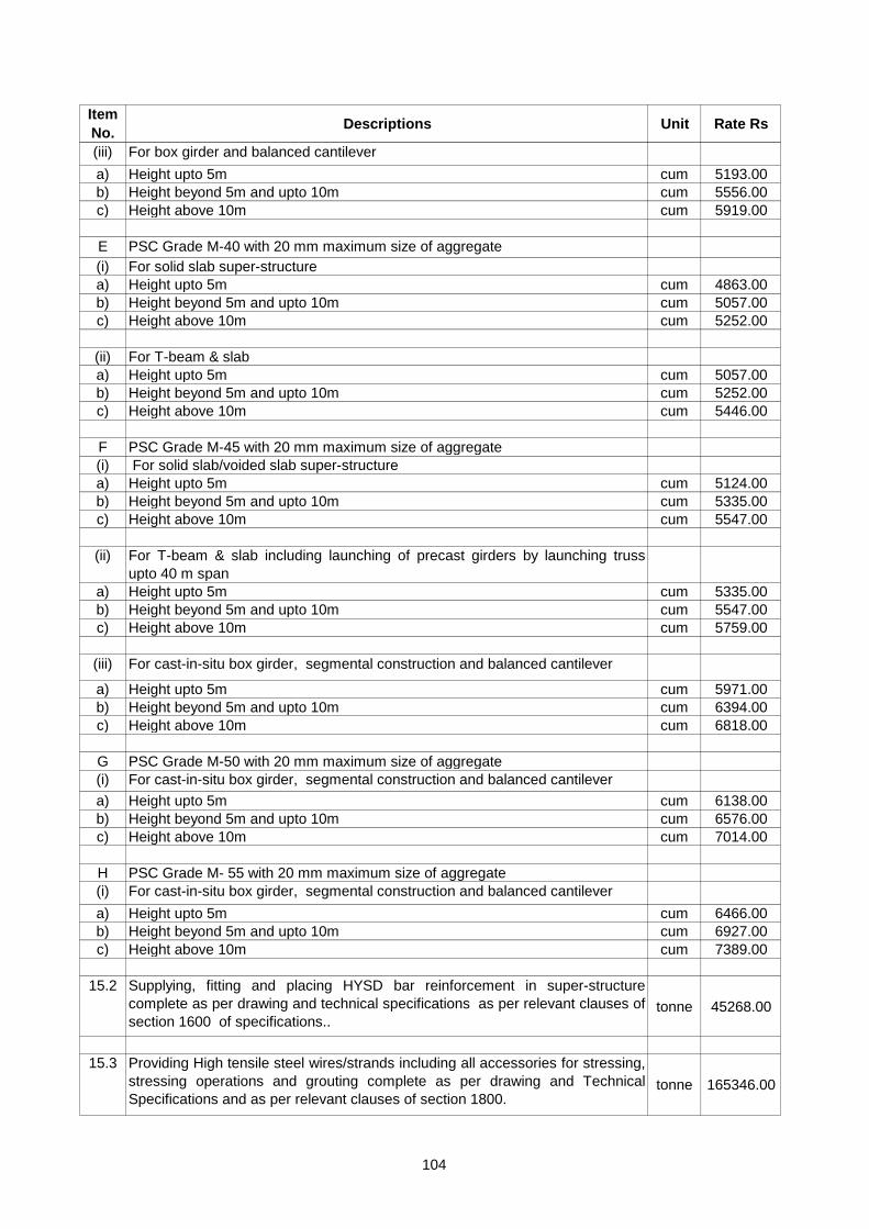
Item
No.Descriptions Unit Rate Rs
(iii) For box girder and balanced cantilever
a) Height upto 5m cum 5193.00
b) Height beyond 5m and upto 10m cum 5556.00
c) Height above 10m cum 5919.00
E PSC Grade M-40 with 20 mm maximum size of aggregate
(i) For solid slab super-structure
a) Height upto 5m cum 4863.00
b) Height beyond 5m and upto 10m cum 5057.00
c) Height above 10m cum 5252.00
(ii) For T-beam & slab
a) Height upto 5m cum 5057.00
b) Height beyond 5m and upto 10m cum 5252.00
c) Height above 10m cum 5446.00
F PSC Grade M-45 with 20 mm maximum size of aggregate
(i) For solid slab/voided slab super-structure
a) Height upto 5m cum 5124.00
b) Height beyond 5m and upto 10m cum 5335.00
c) Height above 10m cum 5547.00
(ii) For T-beam & slab including launching of precast girders by launching truss
upto 40 m span
a) Height upto 5m cum 5335.00
b) Height beyond 5m and upto 10m cum 5547.00
c) Height above 10m cum 5759.00
(iii) For cast-in-situ box girder, segmental construction and balanced cantilever
a) Height upto 5m cum 5971.00
b) Height beyond 5m and upto 10m cum 6394.00
c) Height above 10m cum 6818.00
G PSC Grade M-50 with 20 mm maximum size of aggregate
(i) For cast-in-situ box girder, segmental construction and balanced cantilever
a) Height upto 5m cum 6138.00
b) Height beyond 5m and upto 10m cum 6576.00
c) Height above 10m cum 7014.00
H PSC Grade M- 55 with 20 mm maximum size of aggregate
(i) For cast-in-situ box girder, segmental construction and balanced cantilever
a) Height upto 5m cum 6466.00
b) Height beyond 5m and upto 10m cum 6927.00
c) Height above 10m cum 7389.00
15.2 Supplying, fitting and placing HYSD bar reinforcement in super-structure
complete as per drawing and technical specifications as per relevant clauses of
section 1600 of specifications..tonne 45268.00
15.3 Providing High tensile steel wires/strands including all accessories for stressing,
stressing operations and grouting complete as per drawing and Technical
Specifications and as per relevant clauses of section 1800.tonne 165346.00
104

Item
No.Descriptions Unit Rate Rs
15.4 Providing and laying Cement concrete (mixed in concrete mixture) wearing coat
M-30 grade including reinforcement complete as per drawing and Technical
Specifications and as per relevant clauses of sections 1500, 1700 and Clause
2702 of specifications..
cum 7051.00
15.5 Providing and laying 12 mm thick mastic asphalt wearing course on top of deck
slab excluding prime coat with paving grade bitumen meeting the requirements
given in table 500-29, prepared by using mastic cooker and laid to required
level and slope after cleaning the surface, including providing antiskid surface
with bitumen precoated fine grained hard stone chipping of 9.5 mm nominal size
at the rate of 0.005cum per 10 sqm and at an approximate spacing of 10 cm
center to center in both directions, pressed into surface when the temperature
of surfaces not less than 100 deg. C, protruding 1 mm to 4 mm over mastic
surface, all complete as per clause 515 and 2702 of specifications..
sqm 209.00
15.6 Construction of precast RCC railing of M30 Grade (mixed in concrete mixture),
aggregate size not exceeding 12 mm, true to line and grade, tolurence of
vertical RCC post not to exceed 1 in 500, centre to centre spacing between
vertical post not to exceed 2000 mm, leaving adequate space between vertical
post for expansion, complete as per approved drawings and technical
specification and as per relevant clauses of sections 1500, 1600, 1700 and
clause 2703 of specifications (as per MoST specification drawing SD/202 or
SD/305)
meter 1175.00
15.7 Construction of RCC railing of M30 Grade (mixed in concrete mixture) in-situ
with 12 mm nominal size aggregate, true to line and grade, tolurence of vertical
RCC post not to exceed 1 in 500, centre to centre spacing between vertical
post not to exceed 2000 mm, leaving adequate space between vertical post for
expansion, complete as per approved drawings and technical specifications
and as per relevant clauses of sections 1500, 1600, 1700 and clause 2703 of
specifications (as per MoST specification drawing SD/201 or SD/304)
meter 1142.00
15.8 Providing, fitting and fixing mild steel railing complete as per standard drawing
No.BD/1-88 and Technical Specification and as per relevant clauses of section
1900 and 2700.meter 2202.00
15.9 Providing Drainage Spouts complete as per drawing and Technical specification
and as per clause 2705 of specifications. each 881.00
15.10 Providing PCC M15 (with 40 mm maximum size of aggregate) Grade leveling
course below approach slab complete as per drawing and Technical
specification and as per relevant clauses of section 1700.cum 3050.00
15.11 Providing and laying Reinforced cement concrete approach slab in M-25 grade
concrete including reinforcement and formwork complete as per drawing and
Technical specification and as per relevant clauses of section 1500, 1600, 1700
and clause 2704 of specifications..
cum 6155.00
15.12 Providing and fixing Helical pipes of 600mm dia in voided concrete slabs
including 20mm dia tie rod and sealing joints etc. as per section 1700 and 1800. meter 226.00
105

Item
No.Descriptions Unit Rate Rs
15.13 Providing and laying a burried expansion joint, expansion gap being 20 mm,
covered with 12 mm thick, 200 mm wide galvanised wieldable structural steel
plate as per IS: 2062, placed symmetrical to centre line of the joint, resting
freely over the top surface of the deck concrete, welding of 8 mm dia. 100 mm
long galvanised nails spaced 300 mm c/c along the centre line of the plate, all
as specified in clause 2604.
meter 6605.00
15.14 Filler joint
i) Providing & fixing 2 mm thick and 200mm wide corrugated copper plate in
expansion joint complete as per drawing & Technical Specification and as per
relevant clauses of section 2600.meter 1995.00
ii) Providing & fixing 20 mm thick & 25cm deep compressible fibre board in
expansion joint complete as per drawing & Technical Specification and as per
relevant clauses of section 2600.meter 273.00
iii) Providing and fixing in position 20 mm thick & 300mm deep premoulded joint
filler in expansion joint for fixed ends of simply supported spans not exceeding
10 m to cater for a horizontal movement upto 20 mm, covered with sealant
complete as per drawing and technical specifications and as per relevant
clauses of section 2600.
meter 175.00
iv) Providing and filling joint sealing compound as per drawings and technical
specifications with coarse sand and 6% bitumen by weight and as per relevant
clauses of section 2600.meter 13.00
15.15 Providing and laying of asphaltic plug joint to provide for horizontal movement of
25 mm and vertical movement of 2 mm, depth of joint varying from 75 mm to
100 mm, width varying from 500 mm to 750 mm (in traffic direction), covered
with a closure plate of 200mm x 6mm of wieldable structural steel conforming to
IS: 2062, asphaltic plug to consist of polymer modified bitumen binder,
carefully selected single size aggregate of 12.5 mm nominal size and a heat
resistant foam caulking/backer rod, all as per approved drawings and
specifications and as per relevant clauses of section 2600.
meter 888.00
15.16 Providing and laying of an elastomeric slab steel expansion joint, catering to
right or skew (less than 20 deg., moderately curved with maximum horizontal
movement upto 50 mm, complete as per approved drawings and standard
specifications to be installed by the manufacturer/supplier or their authorised
representative ensuring compliance to the manufacturer's instructions for
installation as per clause 2606 of specifications.
meter 13882.00
15.17 Providing and laying of compression seal joint consisting of steel armoured
nosing at two edges of the joint gap suitably anchored to the deck concrete and
a preformed chloroprene elastomer or closed cell foam joint sealer compressed
and fixed into the joint gap with special adhesive binder to cater for a horizontal
movement upto 40 mm and vertical movement of 3 mm. and as per relevant
clauses of section 2600.
meter 6969.00
106

Item
No.Descriptions Unit Rate Rs
15.18 Providing and laying of a strip seal expansion joint catering to maximum
horizontal movement upto 70 mm, complete as per approved drawings and
standard specifications to be installed by the manufacturer/supplier or their
authorised representative ensuring compliance to the manufacturer's
instructions for installation and as per relevant clauses of section 2600.
meter 11359.00
15.19 Providing and laying of a modular strip Box steel expansion joint including
anchorage catering to a horizontal movement beyond 70 mm and upto 140mm,
complete as per approved drawings and standard specifications to be installed
by the manufacturer/supplier or their authorised representative ensuring
compliance to the manufacturer's instructions for installation and as per relevant
clauses of section 2600.
meter 15021.00
15.20 Providing and laying of a modular strip box seal expansion joint catering to a
horizontal movement beyond 140mm and upto 210mm, complete as per
approved drawings and standard specifications to be installed by the
manufacturer/supplier or their authorised representative ensuring compliance to
the manufacturer's instructions for installation and as per relevant clauses of
section 2600.
meter 16226.00
107

CHAPTER- B-4
RIVER TRAINING AND PROTECTION WORKS
1 Wire crates shall be made from hot dipped galvanized mild steel wire of diameter not
less than 4 mm in annealed condition having tensile strength of 304-450 Mpa
conforming to IS : 280. The galvanizing coating shall be heavy coating for soft
condition conforming to IS : 4826.
The mesh of the crate shall not be more than 150 mm. Wire crates for shallow or
accessible situations sahll be 3 meter x 1.5 meter x 1.25 meter in size.
Wire crates built in-situ, shall not be larger than 7.5 meter x 3 meter x 0.6 meter, nor
smaller than 2 meter x 1 meter x 0.3 meter. Sides of large crates shall be securely
stayed at intervals of not more than 1.50 meter to prevent bulging.
2 The pitching stone shall be sound, hard, durable and fairly regular in shape. Quarry
stone should be used. Round boulders shall not be allowed. The stones subject to
marked deterioration by water or weather shall not be accepted.
The size and weight of pitching stone shall conform to clause 5.3.5.1 of IRC : 89. No
stone, weighing less than 40 kg shall, however, be used. The sizes of spalls shall be a
minimum of 25 mm and shall be suitable to fill the voids in the pitching.
3 MEASUREMENT
(i) The earth work in construction of embankment for guide bund shall be measured in
cubic meter unless otherwise specified.
(ii) The boulders/cement concrete blocks and wire crates in apron shall be measured in
cubic meter.
(iii) The filter and stone pitching shall be mesured separately in cubic meter unless
otherwise specified.
(iv) Rubble stone/cement concrete blocks, flooring and cement concrete bedding shall
be measured in cubic meter for each class of material.
4 Rates
The rate include the cost of all the labour and material required for the completion of
items.
Notes for Specifications :-
(For Detail Refer specification Chapter of River Training & Protection Treatment and MORTH
specification of the same)
108

Item
No.Descriptions Unit Rate Rs
16.1 Providing and laying boulders apron/toe wall on river bed for protection against
scour with stone boulders weighing not less than 40 kg each complete as per
drawing and Technical specification and as per relevant clauses of section 2500.
a) Boulder laid dry without wire crates. cum 789.00
16.2 Providing and laying of boulder apron laid in wire crates made with 4mm dia GI
wire conforming to IS: 280 & IS:4826 in 100mm x 100mm mesh (weaved
diagonally) including 10% extra for laps and joints laid with stone boulders
weighing not less than 40 kg each. and as per relevant clauses of section 2500.
cum 1097.00
16.3 Providing and laying of apron with cement concrete blocks of size 0.5x0.5x0.5 m
cast in-situ and made with nominal mix of M-15 grade cement concrete with a
minimum cement content of 250 kg/cum as per IRC: 21-2000 and as per relevant
clauses of section 2500.
cum 3361.00
16.4 Providing and laying Pitching on slopes laid over prepared filter media including
boulder apron laid dry in front of toe of embankment complete as per drawing and
Technical specifications and as per relevant clauses of section 2500.
a) Stone/Boulder cum 789.00
b) Cement Concrete blocks of size 0.3x0.3 x0.3 m cast in cement concrete of
Grade M15 cum 3361.00
16.5 Providing and laying Filter material underneath pitching in slopes complete as per
drawing and Technical specification and as per relevant clauses of section 2500. cum 796.00
16.6 Providing and Laying of a geotextile filter between pitching and embankment
slopes on which pitching is laid to prevent escape of the embankment material
through the voids of the stone pitching/cement concrete blocks as well as to allow
free movement of water without creating any uplift head on the pitching and as
per relevant clauses of section 700.
sqm 205.00
16.7 Providing and laying Flooring complete as per drawing and Technical
specifications laid over cement concrete bedding and as per relevant clauses of
section 1400, 1700 & 2500.
a) Rubble stone laid in cement mortar 1:3 cum 3197.00
b) Cement Concrete blocks Grade M15 cum 4648.00
16.8 Providing Curtain wall complete as per drawing and Technical specification and
as per relevant clauses of section 1400 , 1700 and 2500.
a) Stone masonry in cement mortar (1:3) cum 2622.00
b) Cement concrete Grade M15 cum 3295.00
CHAPTER-16
RIVER TRAINING AND PROTECTION WORKS
109

Item
No.Descriptions Unit Rate Rs
16.9 Construction of flexible apron 1 m thick comprising of loose stone boulders
weighing not less than 40 kg beyond curtain wall and as per relevant clauses of
section 2500.cum 822.00
16.10 (Providing and construction of a gabain structure for retaining earth with
segments of wire crates of size 7 m x 3 m x 0.6 m each divided into 1.5 m
compartments by cross netting, made from 4 mm galvanised steel wire @ 32 kg
per 10 sqm having minimum tensile strength of 300 Mpa conforming to IS:280
and galvanizing coating conforming to IS:4826, woven into mesh with double
twist, mesh size not exceeding 100 x 100 mm, filled with boulders with least
dimension of 200 mm, all loose ends to be tied with 4 mm galvanised steel wire)
and as per specification in section 2500.
cum 1140.00
16.11 (Providing and constructing gabain structures for erosion control, river training
works and protection works with wire crates of size 2 m x 1 m x 0.3 m each
divided into 1m compartments by cross netting, made from 4 mm galvanised
steel wire @ 32 kg per 10 sqm having minimum tensile strength of 300 Mpa
conforming to IS:280 and galvanizing coating conforming to IS:4826, woven into
mesh with double twist, mesh size not exceeding 100 mm x 100 mm, filled with
boulders with least dimension of 200 mm, all loose ends to be securely tied with
4 mm galvanised steel wire.) and as per specification in section 2500.
cum 1698.00
110

CHAPTER- B-5
REPAIR AND REHABILITATION
1 Care shall be taken to ensure suitable mitigation measures against noise and dust, pollution and
damages to the environs whether temporary or permanent and shall be taken as incidental to work.
2 Traffic management, signage, signalling arrangement, barricading, and lighting arrangement shall be in
accordance with section 100 and with these specifications and shall be considered as incidentals to
work.
3 Adequate precautions shall be taken for safety of personnel, road users and existing services, which,
during execution, shall be considered as incidentals to work.
4 Sealing of Cracks by inection of Epoxy Resin
Surfaces, adjacent to cracks or other areas of application shall be cleaned of dirt, dust, grease, oil
efflorescence or other foreign matter by brushing/water jetting/sand blasting. Acids and corrosives shall
not be permitted for cleaning.
Entry ports shall be provided along the crack at intervals of not more than the thickness of concrete at
the location.
Surface seal material shall be applied to the face of the crack between the entry ports. For through
cracks, surface seal shall be applied to both faces.
Before proceeding with the injection, the surface seal material must gain adequate strength with
respect to concrete strength of the member/injection pressure.
5 Epoxy Injection
Injection of epoxy adhesive shall begin at lowest entry port and continue until there is an appereance of
epoxy adhesive at the next entry port adjacent to the entry port being pumped.
When epoxy adhesive travel is indicated by apperance at the next adjacent port, injection shall be
discontinued on the entry port being pumped and entry port shall be sealed. Thereafter, epoxy injection
shall be transferred to next adjacent port where epoxy adhesive has appeared.
Epoxy adhesive injection shall be performed continuously until cracks are completely filled.
6 Epoxy Mortar for Replacement of Spalled Concrete.
(i) Epoxy primer coat shall be applied with the help of stiff nylon bristle brushes or hard rubber rollers or
spray gun according to the nature of surface and extent of work area.
(ii) Before the primer coat is fully cured, epoxy mortar shall be applied by means of trowels and floats.
(iii) The interval between the application of primer coat and epoxy mortar shall be approximately 15/30
minutes depending upon the ambient temperature.
(iv) Seal Coat shall be applied after 24 hours curing, after mild roughening of the surface of the mortar.
(v) Primer Coat, One kg of resin-hardener mix covers an area of 3-6 square meters per coat depending on
the finish of the concrete
(vi) Epoxy Mortar. One square meter of surface requires approximately 20-24 kg of epoxy mortar when laid
to a thickness of 10mm.
(vii) Seal Coat. 4 to 6 square meters per kg of mix depending on the temperature of application.
7 Testing
Epoxy used for the making mortar shall conform to all requirements and testing procedures as laid
down in Clause 2803.9 of MORTH specification for Road and Bridge.
Notes for Specifications :-
111

8 Grouting
The cement grout shall be mechanically mixed using a system of power-driven paddles of high speed
centrifugal pump and pump to be used shall permit close control of pressures to allow a flexible rate of
injection with minimum clogging of valves and ports.
The grout pump shall be so place as to reduce the waste in cleaning lines.
A continuous supply of grout is preferable to an intermittent one. Consistency of the grout may be
determined by trails strating with thin grout i.e. about 40 litres of water per bag of cement and
progressively decreasing the water content to about 15 litres per bag of cement.
9 Testing
Percolation test done at the end of grouting operation shall give a value of less than 2 lugions.
10 GUNITING/SHOTCRETE
The gunite is a mixture of cement, sand and water. It comprises 100 parts by weight of cement, 300
parts by weight quartz snad, 35-50 parts by weight water and 2 parts by weight approved quick setting
compound. In general, dry mix shotcrete shall be used.
Ordinary Portland cement conforming to IS : 269 shall be used in guniting.
Sand for guniting shall comply with the requirements stipulated in IS : 383. In general, sand should
neither be too coarse to increase the rebound nor too fine to increase the slump. Sand should
preferably have a moisture content between 3 to 6 per cent.
Water/cement ratio for guniting shall fall within the range 0.35 to 0.50 by mass, wet enough to reduce
the rebound. Drying shrinkage may be between 0.06 per cent to 0.10 per cent. The quick setting
compound shall be added at the nozzle with water just before guniting.
11 MEASUREMENT
(i) Measurement for sealing of cracks and injection shall be made by weight of epoxy consumed in kg
for epoxy grouting. For provision of nipples required for grouting, the payment shall be for number of
nipples inserted.
(ii) Measurement for sealing of cracks and injection shall be made by weight of cement consumed in kg
for cement grouting.
(iii) Measurement for application of epoxy mortar for specified thickness shall be per square meter of
surface area of application.
(iv) Measurement for bonding of old and new concrete by epoxy mortar shall be measured in square
meter surface area of interface.
(v) Measurement for guniting/shotcreting, shall be per square meter of surface area of application.
(vi) Payment for replacement/rectification of bearings shall be for each number of bearing assembly
replaced/rectified.
(vii) Dismantling of wearing coat shall be measured in square meter of area of wearing course
dismantled.
(viii) Provision of external prestressing shall be measured in tonnes of H.T. steel strand/wire measured
from anchorage to anchorage before stressing.
4 Rates
The rate include the cost of all the labour and material required for the completion of items.
For Detail Refer specification Chapter of Repair and Rehabilitation and
MORTH Specification of the same
112

Item
No. Descriptions Unit Rate Rs
17.1 Removal of existing cement concrete wearing coat including its disposal complete as
per Technical specification without causing any detrimental effect to any part of the
bridge structure and removal of dismantled material with all lifts and lead upto
1000m(Thickness 75 mm) and as per relevant clauses of section 2800.
sqm 105.00
17.2 Removal of existing asphaltic wearing coat including disposal with all lift and lead upto
1000m and as per relevant clauses of section 2800. sqm 80.00
17.3 Guniting concrete surface with 25mm thick (Average) cement mortar applied with
compressor after cleaning surface and spraying with epoxy complete as per
Technical specification and as per relevant clauses of section 2800.sqm 1121.00
17.4 Providing and inserting nipples with approved fixing compound after drilling holes for
grouting as per Technical specifications including subsequent cutting/removal and
sealing of the hole as necessary of nipples after completion of grouting with
Cement/Epoxy and as per relevant clauses of section 2800.
each 67.00
17.5 Sealing of cracks/porous concrete by injection process through nipples/Grouting
complete as per Technical specification and as per relevant clauses of section 2800.
a) Cement Grout kg 67.00
b) Cement mortar (1:1) Grouting kg 64.00
17.6 Patching of damaged concrete surface with 25mm thick (Average) polymer concrete
and curing compounds, initiator and promoter, available in present formulations, to
be applied as per instructions of manufacturer and as approved by the Engineer and
as per relevant clauses of section 2800.
sqm 1931.00
17.7 Sealing of crack / porous concrete with Epoxy Grout by injection through nipples
complete as per clause 2803.1 and as per relevant clauses of section 2800. kg 1247.00
17.8 Providing and Applying 10mm thick (Average) epoxy mortar over leached, honey
combed and spalled concrete surface and exposed steel reinforcement complete as
per Technical specification and as per relevant clauses of section 2800.sqm 808.00
17.9 Removal of defective concrete, 40mm thick (Average) cleaning the surface
thoroughly, applying the shotcrete mixture mechanically with compressed air under
pressure, comprising of cement, sand, coarse aggregates, water and quick setting
compound in the proportion as per clause 2807.1., sand and coarse aggregates
conforming to IS: 383 and table 1 of IS: 9012 respectively, water cement ratio
ranging from 0.35 to 0.50, density of gunite not less than 2000 kg/cum, strength not
less than 25 Mpa and workmanship conforming to clause 2807.6 and as per relevant
clauses of section 2800.
sqm 269.00
CHAPTER-17
REPAIR AND REHABILITATION
113

Item
No. Descriptions Unit Rate Rs
17.10 Providing and Applying 10mm thick (Average) pre-packed cement based polymer
mortar of strength 45 Mpa at 28 days for replacement of spalled concrete as per
section 2800. sqm 121.00
17.1 Providing Eproxy bonding of new concrete to old concrete as per section 2800. sqm 925.00
17.1 Providing external prestressing with high tensile steel wires/strands including drilling
for passage of prestessing steel, all accessories for stressing and stressing operation
and grouting complete as per drawing and Technical specification and as per relevant
clauses of section 2800.
(a) Span assumed: 25 m per
tonne of
HT
Steel
304450.00
114

115
Annexure “1” Weight, Perimeter and sectional Area of Metric Steel Bars.
Diameter (mm)
Weight per meter
in kg
Perimeter Cm
Sect ion l Area of
Steel bars in Sq.
Cms.
5 0.154 1.571 0.196
6 0.222 1.887 0.282
7 0.302 2.2 0.385
8 0.395 2.514 0.503
10 0.617 3.143 0.786
12 0.888 3.771 1.131
14 1.208 4.4 1.54
16 1.578 5.028 2.011
18 1.998 5.657 2.546
20 2.466 6.286 3.143
22 2.984 6.914 3.803
24 3.551 7.543 4.526
25 3.853 7.857 4.911
36 4.163 8.171 5.311
28 4.834 8.8 6.16
30 5.549 9.428 7.071
32 6.31 10.057 8.046
34 7.13 10.686 9.083
36 7.99 11.314 10.183
40 9.87 12.571 12.571
45 12.5 14.143 15.911
50 15.41 15.714 19.643

116
Width in mm.
Thickness in MM.
5
5.5
6
7
8
9
10
11 12
14
16
18
20
22
25
1
2
3
4
5
6
7
8
9 10
11
12
13
14
15
16
12
0.471
0.518
0.565
0.659
0.753
0.848
0.942
1.036 1.130
1.319
1.507
1.695
1.884
2.072
2.355
16
0.628
0.691
0.753
0.879
1.005
1.130
1.256
1.381 1.507
1.759
2.009
2.261
2.512
2.763
3.140
20
0.785
0.863
0.942
1.099
1.256
1.413
1.570
1.727 1.884
2.198
2.512
2.826
3.140
3.454
3.925
25
0.981
1.079
1.177
1.374
1.570
1.766
1.962
2.158 2.355
2.747
3.140
3.532
3.924
4.317
4.906
32
1.256
1.381
1.507
1.758
2.009
2.360
2.512
2.763 3.014
3.516
4.019
4.521
5.023
5.526
6.279
40
1.570
1.727
1.884
2.198
2.512
2.826
3.140
3.453 3.768
4.395
5.023
5.651
6.279
6.907
7.849
50
1.962
2.158
2.355
2.747
3.140
3.532
3.924
4.317 4.709
5.494
6.279
7.064
7.849
8.634
9.811
63
2.472
2.720
2.967
3.461
3.956
4.450
4.945
5.439 5.934
6.923
7.912
8.901
9.890
10.879
12.362
80
3.139
3.454
3.768
4.395
5.023
5.6 51
6.279
6.907 7.535
8.791
10.470
11.303
12.585
13.814
15.398
100
3.924
4.317
4.709
5.494
6.279
7.064
7.849
8.634 9.419
10.989
12.558
14.128
15.698
17.268
19.622
125
4.905
5.396
5.887
6.868
7.849
8.830
9.811
10.792 11.773
13.736
15.698
17.660
19.622
21.585
24.520
160
6.275
6.907
7.536
8.791
10.047
11.303
12.558
13.814 15.07
17.582
20.093
22.605
25.117
27.628
31.396
Annexure “2”
Weight of Flats per meter

117
Annexure “3”
Approximate outer D I Meter and thickness of steel tubes
Nominal Bore
Approximate
outer dia
Thickness in M. M.
Thickness in Inch
S.W .G.
W eight per meter of
black tube plain ends
in kg
M.M.
Inc h
M.M.
I n c h
Light
Medium
Heavy
Light
Medium
Heavy
Light
Medium
Heavy
Light
Medium
Heavy
1
2
3
4
5
6
7
8
9
10
11
12
13
14
15
16
15
1/2"
21.3
27/32"
2.00
2.65
3.25
0.08
0.10
0.13
14
12
10
0.95
1.22
1.45
20
3/4"
26.9
11/16"
2.35
2.65
3.25
0.09
0.10
0.13
13
12
10
1.41
1.58
1.90
25
1"
33.7
111/32"
2.65
3.25
4.05
0.10
0.13
0.16
12
10
8
2.01
2.41
2.97
32
1¼"
42.4
111/16"
2.65
3.25
4.05
0.10
0.13
0.16
12
10
8
2.58
3.11
3.84
40
1-1/2"
48.3
129/32"
2.90
3.25
4.05
0.12
0.13
0.16
11
10
8
3.25
3.61
4.43
50
2"
60.3
23/8"
2.90
3.65
4.50
0.12
0.14
0.18
11
9
7
4.11
5.10
6.17
65
2-1/2"
76.10
3"
3.25
3.65
4.50
0.13
0.14
0.18
10
9
7
0.80
6.51
7.90
80
3"
88.9
3-1/2"
3.25
4.05
4.85
0.13
0.16
0.19
10
8
6
6.81
8.47
10.00
100
4"
114.3
4-1/2"
6.25
4.50
5.40
0.14
0.18
0.21
9
7
5
9.89
12.10
14.40
125
5"
139.7
5-1/2"
.-
4.85
5.40
0.19
0.21
6
5 _
16.20
17.80
150
6"
165.1
6-1/2
-
4.85
5.40
0.19
0.21
6
5 _
19.20
21.20

118
Annexure “4” IMPORTANT CONVERSION TABLE
Unit Conversion
1 kiloliter 1000 liter
1 kiloliter 1 cum
1cum 1000 liter
1cu feet 28.317 liter
0.028 cum
6.24 gallons imperial
7.48 gallons. U. s
1 cum 219.97 gallons imperial
264.17 gallons us
1 liter 0.22 gallons imp(britsh)
1 gallons imperial 1.2 u.s gallons
1gallons imperial 4.546 liter
1 H.P 0.7457 kilowatt
1 H.P hr 0.7457 k.w.hr
1 metric HP 733.50 watt
1 kilowatt 1000 watt
1.341 HP
1.36 HP
1 Acre 43560 sq feet
1 sq kilo meter 100 hectare
1 sq mile 259 hectare
640 acre
2.59 sq kilo meter
1 cubic feet x .02832 cubic meters
1 cubic feet x 2.832 x 10⁴ cubic centimeters
1 cubic feet x 6.229 imperial gallons
1 cubic feet x 28.32 litters
1 cubic feet per second x .02831 cubic meter per second
cubic feet per second x 0.6463 million u.s gallon per day
cubic meter per second x 2.282x 10⁷ u.s gallons per minutes
gallons imperial x 4.546 litters
gallons imperial x 4.546 x 10⁻³ cubic meters
gram force per centimeter x 9.807x10⁻³ Newton per minute
kilo gram force per square meter x 98.07 kilo Pascal


![ReGAN: RE[LAX|BAR|INFORCE] based Sequence Generation …ofdiscretetokens. Secondly,GANscanonlygiveascoreonceanentiresequencehasbeen generated,whichisaproblemwithlargesequencesoftokens.](https://static.fdocuments.us/doc/165x107/5e600781d059d64acf779b55/regan-relaxbarinforce-based-sequence-generation-ofdiscretetokens-secondlyganscanonlygiveascoreonceanentiresequencehasbeen.jpg)