Blandin Broadband Community grant projects Sherburne Presentation
Address Editor Application Deployment and
Configuration Guide
Address Editor Application 3.0 for ArcGIS Server 10.2
By:
North Point Geographic Solutions, LLC
394 S. Lake Ave
DeWitt-Seitz Marketplace Suite 400
Duluth, MN 55802
Phone: 218-720-NPGS (6747)
Fax: 218-720-9382
www.northpointgis.com
Last Revised: 8/06/15
2
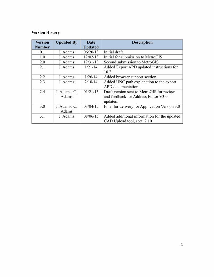
Version History
Version
Number
Updated By Date
Updated
Description
0.1 J. Adams 06/20/13 Initial draft
1.0 J. Adams 12/02/13 Initial for submission to MetroGIS
2.0 J. Adams 12/31/13 Second submission to MetroGIS
2.1 J. Adams 1/21/14 Added Export APD updated instructions for
10.2
2.2 J. Adams 1/26/14 Added browser support section
2.3 J. Adams 2/10/14 Added UNC path explanation to the export
APD documentation
2.4 J. Adams, C.
Adams
01/21/15 Draft version sent to MetroGIS for review
and feedback for Address Editor V3.0
updates.
3.0 J. Adams, C.
Adams
03/04/15 Final for delivery for Application Version 3.0
3.1 J. Adams 08/06/15 Added additional information for the updated
CAD Upload tool, sect. 2.10

3
Table of Contents
1. INTRODUCTION ......................................................................................................... 7
2. APPLICATION INSTALLATION INSTRUCTIONS ................................................... 7
2.1 ArcGIS Server Address Point Feature Service Setup ............................................... 7
2.2 Web Application Installation ..................................................................................... 8
2.3 Log-in Page Header Modification ...........................................................................11
2.4 Installation of the Authentication Mechanisms........................................................11
2.5 Setting up the Users Table - SQL Server ................................................................ 12
2.6 Setting up the Users - Microsoft Access ................................................................. 12
2.7 Setting up the Geoprocessing Tasks ........................................................................ 13
2.8 Setting up the APD Point Extraction Task .............................................................. 13
2.9 Setting Up the Print Map Task ............................................................................... 16
2.10 Setting up the CAD Uploading Geoprocessing Task ............................................ 18
2.11 Reporting Service Setup ........................................................................................ 21
2.12 Publishing the Address Points Change Table ........................................................ 24
2.13 Application User Interface Configuration ............................................................. 24
2.13 Setting up the Unique ID Functionality ................................................................ 30
3. ADDRESS EDITOR APPLICATION USER INSTRUCTIONS ................................ 31
3.1 Recommended Browsers ....................................................................................... 31
3.2 Address Editor Application Login and Basic Tools ............................................... 31
3.3 Inspecting and Editing Existing Address Points .................................................... 32
3.4 Bulk Editing Address Points ................................................................................... 33
3.5 Adding New Address Points .................................................................................. 35
3.6 Attribute Editing Selection ...................................................................................... 36
3.7 Uploading Files ....................................................................................................... 37
3.8 Exporting Address Points ....................................................................................... 38
3.9 Printing a Map........................................................................................................ 39
3.10 Generating a Report .............................................................................................. 40
3.10.1 Deleted Addresses in Printed Reports ............................................................ 42
3.11 Passing an Address Point to Another Authority ................................................... 42
3.12 Proposed Address Tool.......................................................................................... 43
4
4.0 OTHER MAP FEATURES ........................................................................................ 45
4.1 Map Legend ............................................................................................................ 45
4.2 Layers Toggling ...................................................................................................... 45
4.3 Parcel Information .................................................................................................. 45
4.4 Find an Address....................................................................................................... 46
4.5 Parcel Search Function ........................................................................................... 46
4.6 Duplicate Address Checking ................................................................................... 47
5. ADDRESS EDITOR SUPPORT .................................................................................. 48
5
Table of Figures
Figure 1: Feature Service Publishing .................................................................................. 8 Figure 2: IIS Application Setup .......................................................................................... 9 Figure 3: Modify Files Folder Security Permissions .......................................................... 9
Figure 4: Modify the Advanced Application Settings....................................................... 10 Figure 5: Modify the Application Pool Settings ............................................................... 10 Figure 6: Code for Authentication Database ......................................................................11 Figure 7: Change the Table Name if Different Than 'Users' ............................................. 12 Figure 8: IIS Application Pool 32-Bit Configuration ....................................................... 13
Figure 9: exportAPD.py Setup .......................................................................................... 14 Figure 10: Publish the Geoprocessing Service Result ...................................................... 15
Figure 11: Change Input Mode ......................................................................................... 16 Figure 12: Enable Printing Geoprocessing Tool ............................................................... 16 Figure 13: Print Service Properties ................................................................................... 17 Figure 14: Set Print Service as Asynchronous .................................................................. 17
Figure 15: Setting the Token Timeout Period ................................................................... 18 Figure 16: Changing the output spatial reference ............................................................. 19 Figure 17: Updating the maximum of features returned ................................................... 19
Figure 18: Parameter Entry for the CAD Uploading Geoprocessing Tool ....................... 20 Figure 19: Publishing CAD Upload Tool from the Geoprocessing Results ..................... 20
Figure 20: Turning on the Upload Functionality for the Geoprocessing Service ............. 21 Figure 21: Report Tool Toolbox ........................................................................................ 22 Figure 22: Report Tool Default Parameters ...................................................................... 22
Figure 23: Publish Report Tool Geoprocessing Tool ........................................................ 22
Figure 24: Service Editor Window ................................................................................... 23 Figure 25: Map Interaction Tools ...................................................................................... 31 Figure 26: “Proposed” Status Pop-up Notice.................................................................... 32
Figure 27: Address Point Attributes in Non-Edit Mode.................................................... 32 Figure 28: Saving Address Point Edits ............................................................................. 33
Figure 29: Moving an Existing Address Point .................................................................. 33 Figure 30: Bulk Editing Tool ............................................................................................ 34 Figure 31: Active Bulk Editing ......................................................................................... 34 Figure 32: Draw Polygon Around Bulk Editing Selection ............................................... 34
Figure 33: Selected Points Display ................................................................................... 35 Figure 34: Add Individual Address Point.......................................................................... 35 Figure 35: Add Hypothetical Address ............................................................................... 36 Figure 36: Multiple Address Point Scrolling .................................................................... 36
Figure 37: Attribute Editing Selection .............................................................................. 36 Figure 38: “Upload a File” Tool ....................................................................................... 37 Figure 39: File Selection Drop-down ............................................................................... 37
Figure 40: Done Editing Uploaded File ............................................................................ 38 Figure 41: Export Address Points Tool ............................................................................. 38
6
Figure 42: Drawing an Extent to Export ........................................................................... 39 Figure 43: Print a Map Tool .............................................................................................. 39 Figure 44: Print Map Options Dialog ............................................................................... 40
Figure 45: Generate a Report Tool .................................................................................... 40 Figure 46: Generate a Report Pop-up Screen ................................................................... 41 Figure 47: Example Report Output Configuration ........................................................... 41 Figure 48: Report by Date Pop-up Screen ........................................................................ 42 Figure 49: Example Report by Date - Deleted Address .................................................... 42
Figure 50: Passing a Point to Another Address Authority ................................................ 43 Figure 51: Map of Unassigned Address Points ................................................................. 43 Figure 52: Proposed Address Tool .................................................................................... 44 Figure 53: Proposed Address Report Screen .................................................................... 44
Figure 54: Map Application Legend ................................................................................. 45 Figure 55: Application Layer Table of Contents ............................................................... 45
Figure 56: Parcel Information Panel ................................................................................. 46 Figure 57: Find an Address Panel ..................................................................................... 46
Figure 58: Parcel Search Results ...................................................................................... 47 Figure 59: Duplicate Address Check ................................................................................ 47
7
1. INTRODUCTION
The Address Editor Application Deployment and Configuration Guide outlines the
activities needed to complete a deployment of the Address Editor application for the
Metropolitan Council (MetroGIS). After properly executing the installation instructions,
address authorities should have a full working copy of the application.
An application user guide has also been included in this document to provide basic
instructions on how to use the Address Editor Application. It should be noted that as the
application evolves in functionality, it is the intention that this document will also evolve.
2. APPLICATION INSTALLATION INSTRUCTIONS
** The following instructions are targeted for ArcGIS Server version 10.2.
The application consists of several pieces: the web application, login application, users
table, data for the services, and Python folder containing the files necessary for
geoprocessing tasks.
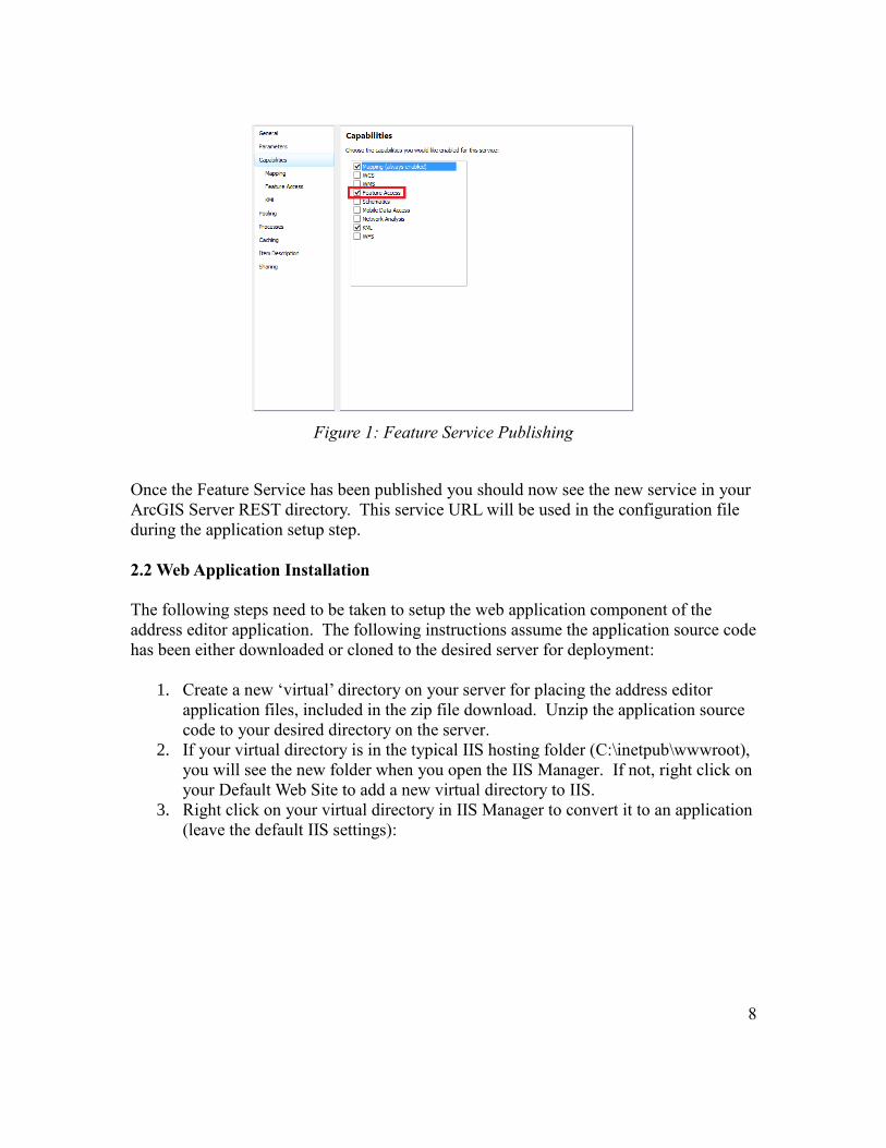
2.1 ArcGIS Server Address Point Feature Service Setup
The address editor application requires an ArcGIS Server Feature Service in order to edit
points through the application. In order to publish a Feature Service all layers in the map
document must be in an ArcSDE Geodatabase. Once the address points and any other
reference layers you would like to have in the application are in SDE, author your map
document to be published to ArcGIS Server. During the publishing process be sure to
select “Feature Access” from the list of capabilities.
8
Figure 1: Feature Service Publishing
Once the Feature Service has been published you should now see the new service in your
ArcGIS Server REST directory. This service URL will be used in the configuration file
during the application setup step.
2.2 Web Application Installation
The following steps need to be taken to setup the web application component of the
address editor application. The following instructions assume the application source code
has been either downloaded or cloned to the desired server for deployment:
1. Create a new ‘virtual’ directory on your server for placing the address editor
application files, included in the zip file download. Unzip the application source
code to your desired directory on the server.
2. If your virtual directory is in the typical IIS hosting folder (C:\inetpub\wwwroot),
you will see the new folder when you open the IIS Manager. If not, right click on
your Default Web Site to add a new virtual directory to IIS.
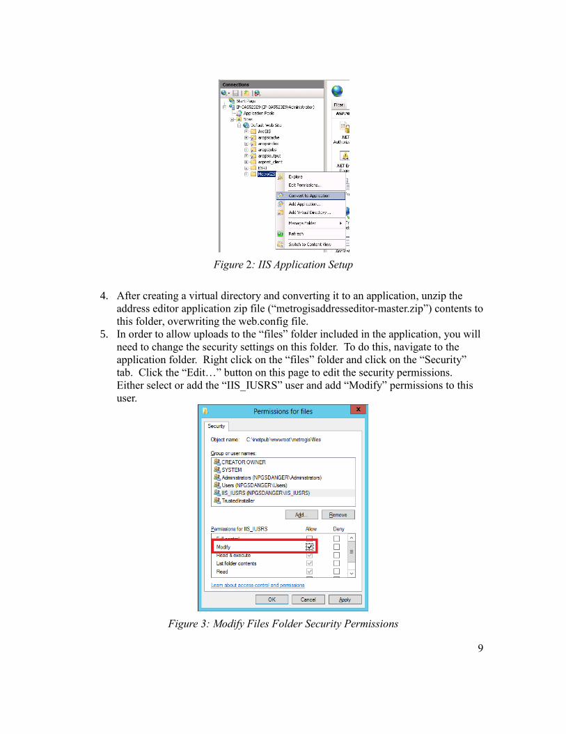
3. Right click on your virtual directory in IIS Manager to convert it to an application
(leave the default IIS settings):
9
Figure 2: IIS Application Setup
4. After creating a virtual directory and converting it to an application, unzip the
address editor application zip file (“metrogisaddresseditor-master.zip”) contents to
this folder, overwriting the web.config file.
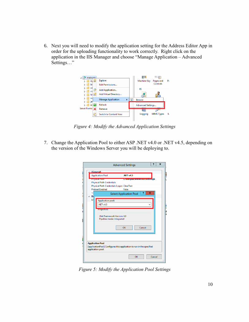
5. In order to allow uploads to the “files” folder included in the application, you will
need to change the security settings on this folder. To do this, navigate to the
application folder. Right click on the “files” folder and click on the “Security”
tab. Click the “Edit…” button on this page to edit the security permissions.
Either select or add the “IIS_IUSRS” user and add “Modify” permissions to this
user.
Figure 3: Modify Files Folder Security Permissions
10
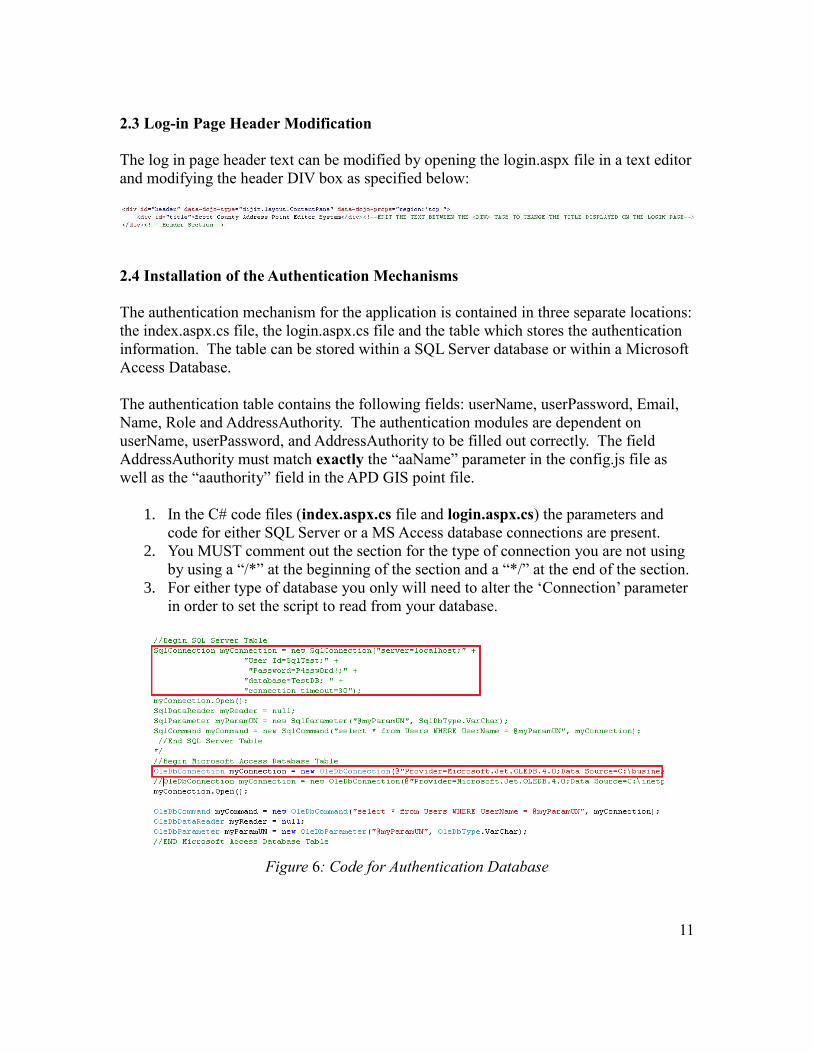
6. Next you will need to modify the application setting for the Address Editor App in
order for the uploading functionality to work correctly. Right click on the
application in the IIS Manager and choose “Manage Application – Advanced
Settings…”
Figure 4: Modify the Advanced Application Settings
7. Change the Application Pool to either ASP .NET v4.0 or .NET v4.5, depending on
the version of the Windows Server you will be deploying to.
Figure 5: Modify the Application Pool Settings
11
2.3 Log-in Page Header Modification
The log in page header text can be modified by opening the login.aspx file in a text editor
and modifying the header DIV box as specified below:
2.4 Installation of the Authentication Mechanisms
The authentication mechanism for the application is contained in three separate locations:
the index.aspx.cs file, the login.aspx.cs file and the table which stores the authentication
information. The table can be stored within a SQL Server database or within a Microsoft
Access Database.
The authentication table contains the following fields: userName, userPassword, Email,
Name, Role and AddressAuthority. The authentication modules are dependent on
userName, userPassword, and AddressAuthority to be filled out correctly. The field
AddressAuthority must match exactly the “aaName” parameter in the config.js file as
well as the “aauthority” field in the APD GIS point file.
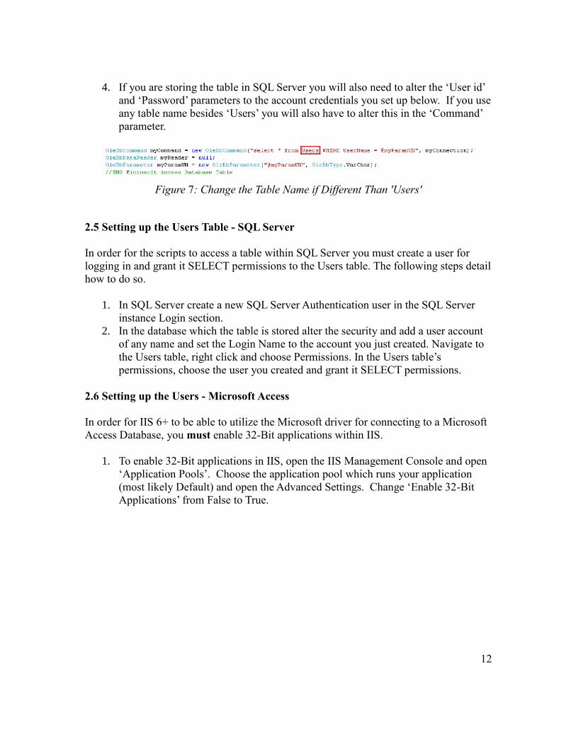
1. In the C# code files (index.aspx.cs file and login.aspx.cs) the parameters and
code for either SQL Server or a MS Access database connections are present.
2. You MUST comment out the section for the type of connection you are not using
by using a “/*” at the beginning of the section and a “*/” at the end of the section.
3. For either type of database you only will need to alter the ‘Connection’ parameter
in order to set the script to read from your database.
Figure 6: Code for Authentication Database
12
4. If you are storing the table in SQL Server you will also need to alter the ‘User id’
and ‘Password’ parameters to the account credentials you set up below. If you use
any table name besides ‘Users’ you will also have to alter this in the ‘Command’
parameter.
Figure 7: Change the Table Name if Different Than 'Users'
2.5 Setting up the Users Table - SQL Server
In order for the scripts to access a table within SQL Server you must create a user for
logging in and grant it SELECT permissions to the Users table. The following steps detail
how to do so.
1. In SQL Server create a new SQL Server Authentication user in the SQL Server
instance Login section.
2. In the database which the table is stored alter the security and add a user account
of any name and set the Login Name to the account you just created. Navigate to
the Users table, right click and choose Permissions. In the Users table’s
permissions, choose the user you created and grant it SELECT permissions.
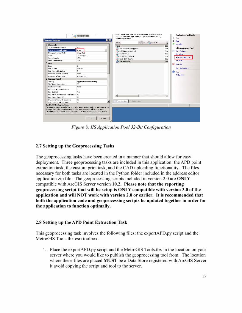
2.6 Setting up the Users - Microsoft Access
In order for IIS 6+ to be able to utilize the Microsoft driver for connecting to a Microsoft
Access Database, you must enable 32-Bit applications within IIS.
1. To enable 32-Bit applications in IIS, open the IIS Management Console and open
‘Application Pools’. Choose the application pool which runs your application
(most likely Default) and open the Advanced Settings. Change ‘Enable 32-Bit
Applications’ from False to True.
13
Figure 8: IIS Application Pool 32-Bit Configuration
2.7 Setting up the Geoprocessing Tasks
The geoprocessing tasks have been created in a manner that should allow for easy
deployment. Three geoprocessing tasks are included in this application: the APD point
extraction task, the custom print task, and the CAD uploading functionality. The files
necessary for both tasks are located in the Python folder included in the address editor
application zip file. The geoprocessing scripts included in version 2.0 are ONLY
compatible with ArcGIS Server version 10.2. Please note that the reporting
geoprocessing script that will be setup is ONLY compatible with version 3.0 of the
application and will NOT work with version 2.0 or earlier. It is recommended that
both the application code and geoprocessing scripts be updated together in order for
the application to function optimally.
2.8 Setting up the APD Point Extraction Task
This geoprocessing task involves the following files: the exportAPD.py script and the
MetroGIS Tools.tbx esri toolbox.
1. Place the exportAPD.py script and the MetroGIS Tools.tbx in the location on your
server where you would like to publish the geoprocessing tool from. The location
where these files are placed MUST be a Data Store registered with ArcGIS Server
it avoid copying the script and tool to the server.
14
2. Open the “MetroGIS Tools” ArcToolbox that is included with the application
package under the Python folder in ArcMap.
3. Open ArcMap and add your address points feature class that resides in an SDE
database.
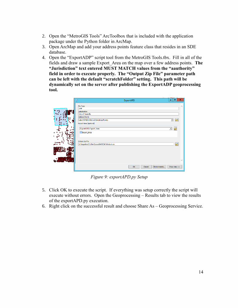
4. Open the “ExportADP” script tool from the MetroGIS Tools.tbx. Fill in all of the
fields and draw a sample Export_Area on the map over a few address points. The
“Jurisdiction” text entered MUST MATCH values from the “aauthority”
field in order to execute properly. The “Output Zip File” parameter path
can be left with the default “scratchFolder” setting. This path will be
dynamically set on the server after publishing the ExportADP geoprocessing
tool.
Figure 9: exportAPD.py Setup
5. Click OK to execute the script. If everything was setup correctly the script will
execute without errors. Open the Geoprocessing – Results tab to view the results
of the exportAPD.py execution.
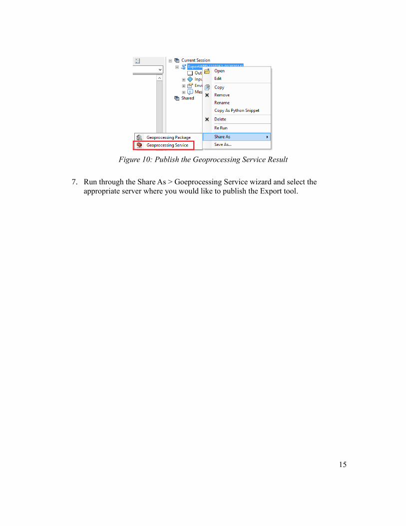
6. Right click on the successful result and choose Share As – Geoprocessing Service.
15
Figure 10: Publish the Geoprocessing Service Result
7. Run through the Share As > Goeprocessing Service wizard and select the
appropriate server where you would like to publish the Export tool.
16
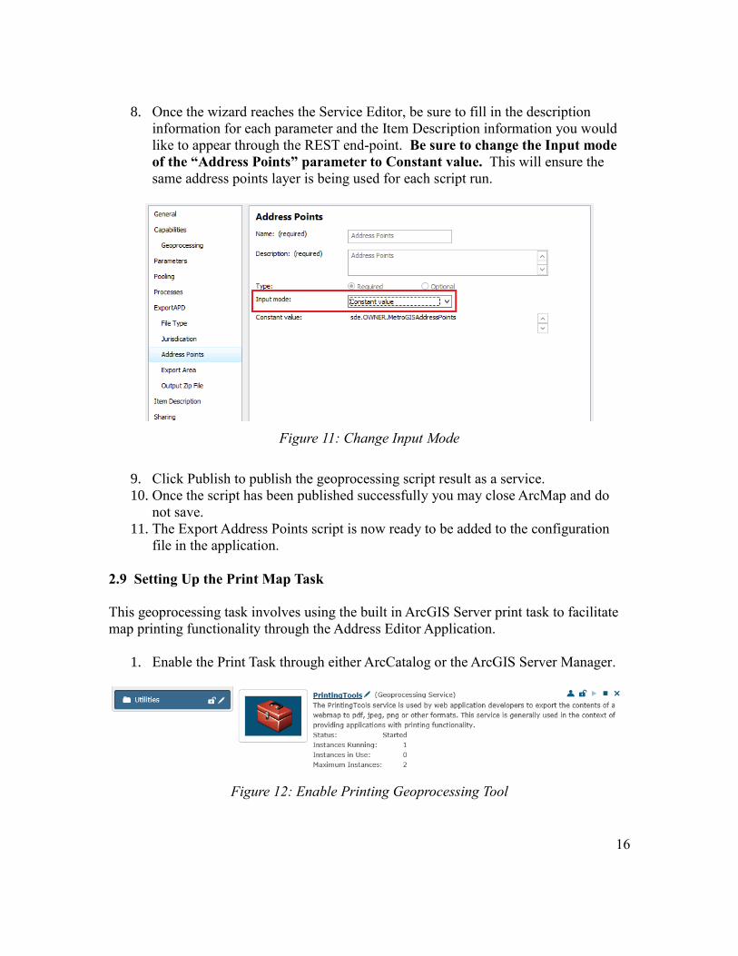
8. Once the wizard reaches the Service Editor, be sure to fill in the description
information for each parameter and the Item Description information you would
like to appear through the REST end-point. Be sure to change the Input mode
of the “Address Points” parameter to Constant value. This will ensure the
same address points layer is being used for each script run.
Figure 11: Change Input Mode
9. Click Publish to publish the geoprocessing script result as a service.
10. Once the script has been published successfully you may close ArcMap and do
not save.
11. The Export Address Points script is now ready to be added to the configuration
file in the application.
2.9 Setting Up the Print Map Task
This geoprocessing task involves using the built in ArcGIS Server print task to facilitate
map printing functionality through the Address Editor Application.
1. Enable the Print Task through either ArcCatalog or the ArcGIS Server Manager.
Figure 12: Enable Printing Geoprocessing Tool
17
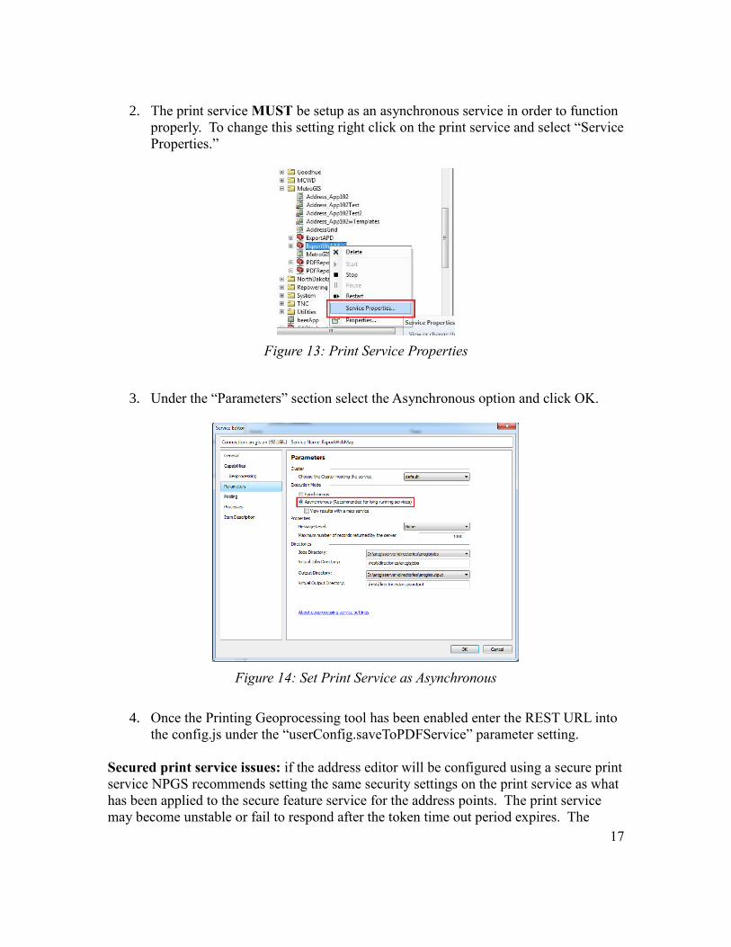
2. The print service MUST be setup as an asynchronous service in order to function
properly. To change this setting right click on the print service and select “Service
Properties.”
Figure 13: Print Service Properties
3. Under the “Parameters” section select the Asynchronous option and click OK.
Figure 14: Set Print Service as Asynchronous
4. Once the Printing Geoprocessing tool has been enabled enter the REST URL into
the config.js under the “userConfig.saveToPDFService” parameter setting.
Secured print service issues: if the address editor will be configured using a secure print
service NPGS recommends setting the same security settings on the print service as what
has been applied to the secure feature service for the address points. The print service
may become unstable or fail to respond after the token time out period expires. The
18
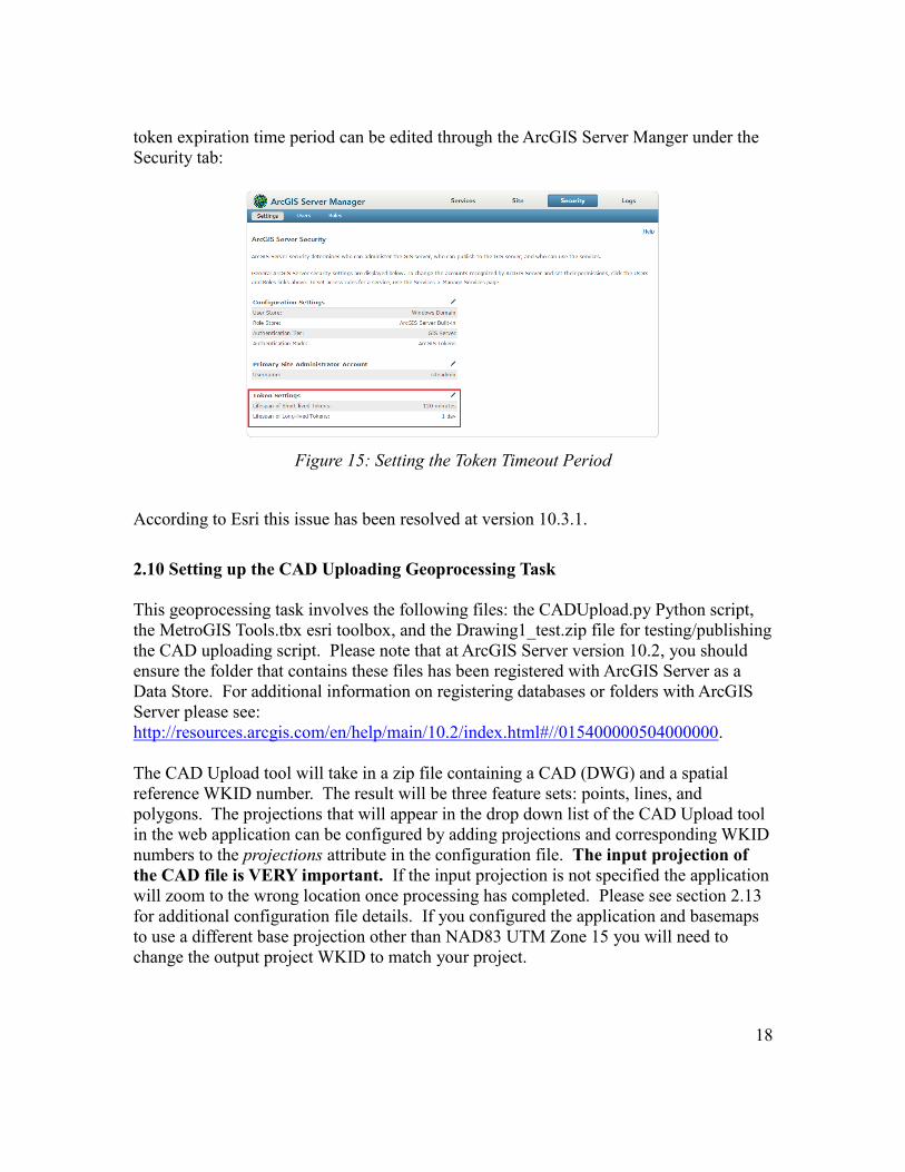
token expiration time period can be edited through the ArcGIS Server Manger under the
Security tab:
Figure 15: Setting the Token Timeout Period
According to Esri this issue has been resolved at version 10.3.1.
2.10 Setting up the CAD Uploading Geoprocessing Task
This geoprocessing task involves the following files: the CADUpload.py Python script,
the MetroGIS Tools.tbx esri toolbox, and the Drawing1_test.zip file for testing/publishing
the CAD uploading script. Please note that at ArcGIS Server version 10.2, you should
ensure the folder that contains these files has been registered with ArcGIS Server as a
Data Store. For additional information on registering databases or folders with ArcGIS
Server please see:
http://resources.arcgis.com/en/help/main/10.2/index.html#//015400000504000000.
The CAD Upload tool will take in a zip file containing a CAD (DWG) and a spatial
reference WKID number. The result will be three feature sets: points, lines, and
polygons. The projections that will appear in the drop down list of the CAD Upload tool
in the web application can be configured by adding projections and corresponding WKID
numbers to the projections attribute in the configuration file. The input projection of
the CAD file is VERY important. If the input projection is not specified the application
will zoom to the wrong location once processing has completed. Please see section 2.13
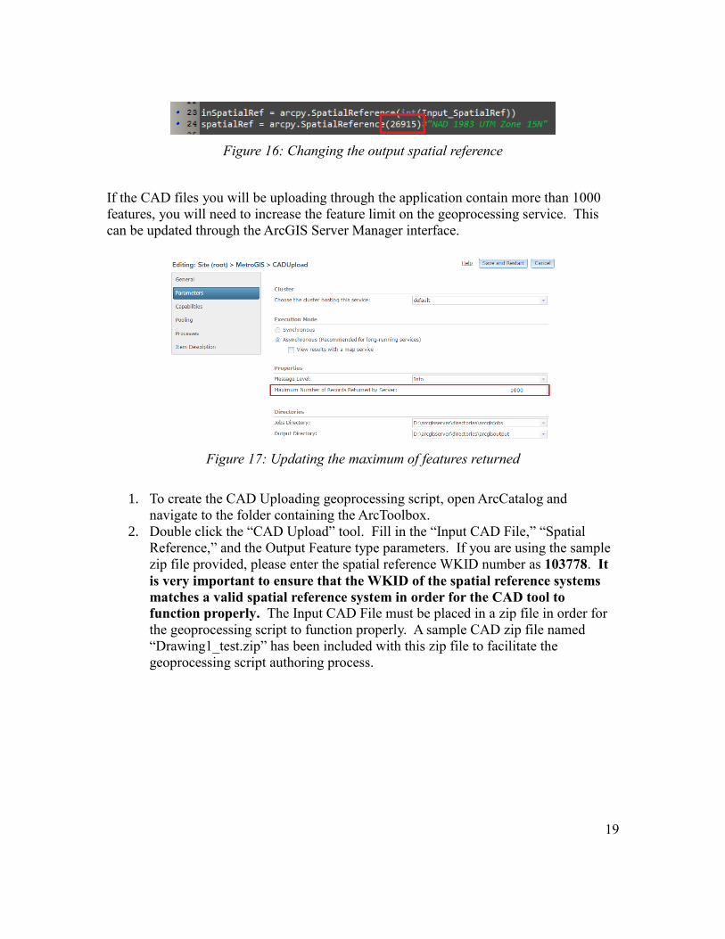
for additional configuration file details. If you configured the application and basemaps
to use a different base projection other than NAD83 UTM Zone 15 you will need to
change the output project WKID to match your project.
19
Figure 16: Changing the output spatial reference
If the CAD files you will be uploading through the application contain more than 1000
features, you will need to increase the feature limit on the geoprocessing service. This
can be updated through the ArcGIS Server Manager interface.
Figure 17: Updating the maximum of features returned
1. To create the CAD Uploading geoprocessing script, open ArcCatalog and
navigate to the folder containing the ArcToolbox.
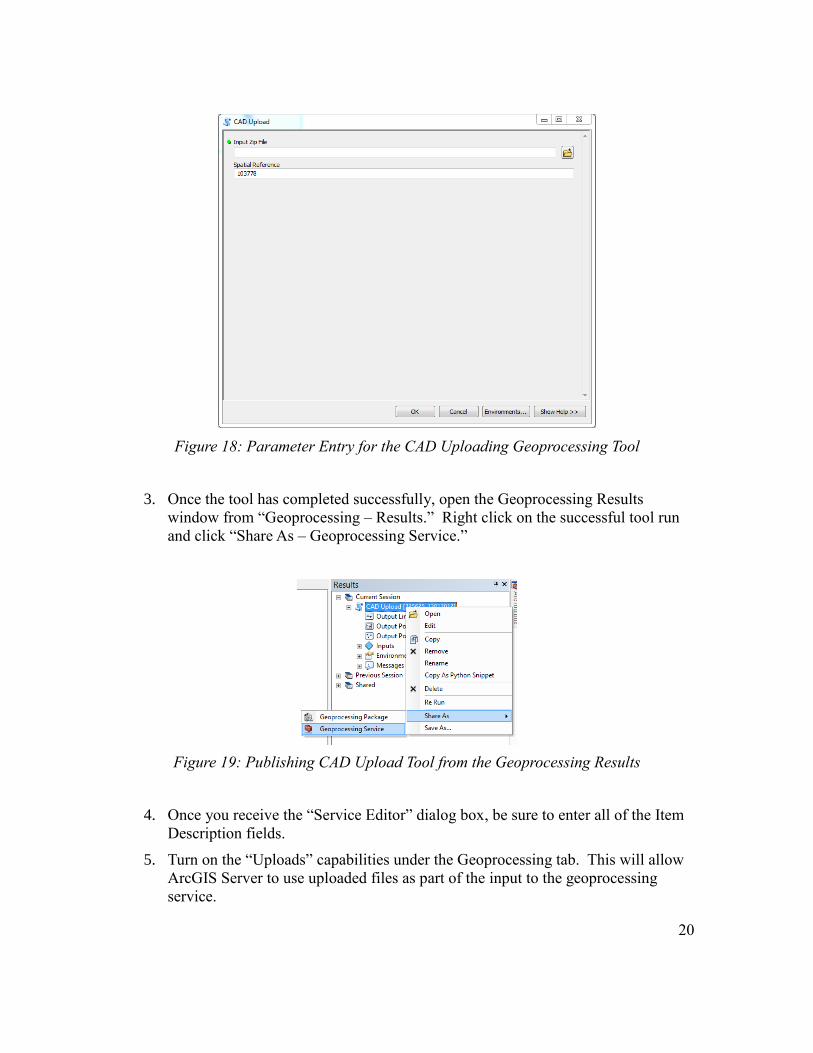
2. Double click the “CAD Upload” tool. Fill in the “Input CAD File,” “Spatial
Reference,” and the Output Feature type parameters. If you are using the sample
zip file provided, please enter the spatial reference WKID number as 103778. It
is very important to ensure that the WKID of the spatial reference systems
matches a valid spatial reference system in order for the CAD tool to
function properly. The Input CAD File must be placed in a zip file in order for
the geoprocessing script to function properly. A sample CAD zip file named
“Drawing1_test.zip” has been included with this zip file to facilitate the
geoprocessing script authoring process.
20
Figure 18: Parameter Entry for the CAD Uploading Geoprocessing Tool
3. Once the tool has completed successfully, open the Geoprocessing Results
window from “Geoprocessing – Results.” Right click on the successful tool run
and click “Share As – Geoprocessing Service.”
Figure 19: Publishing CAD Upload Tool from the Geoprocessing Results
4. Once you receive the “Service Editor” dialog box, be sure to enter all of the Item
Description fields.
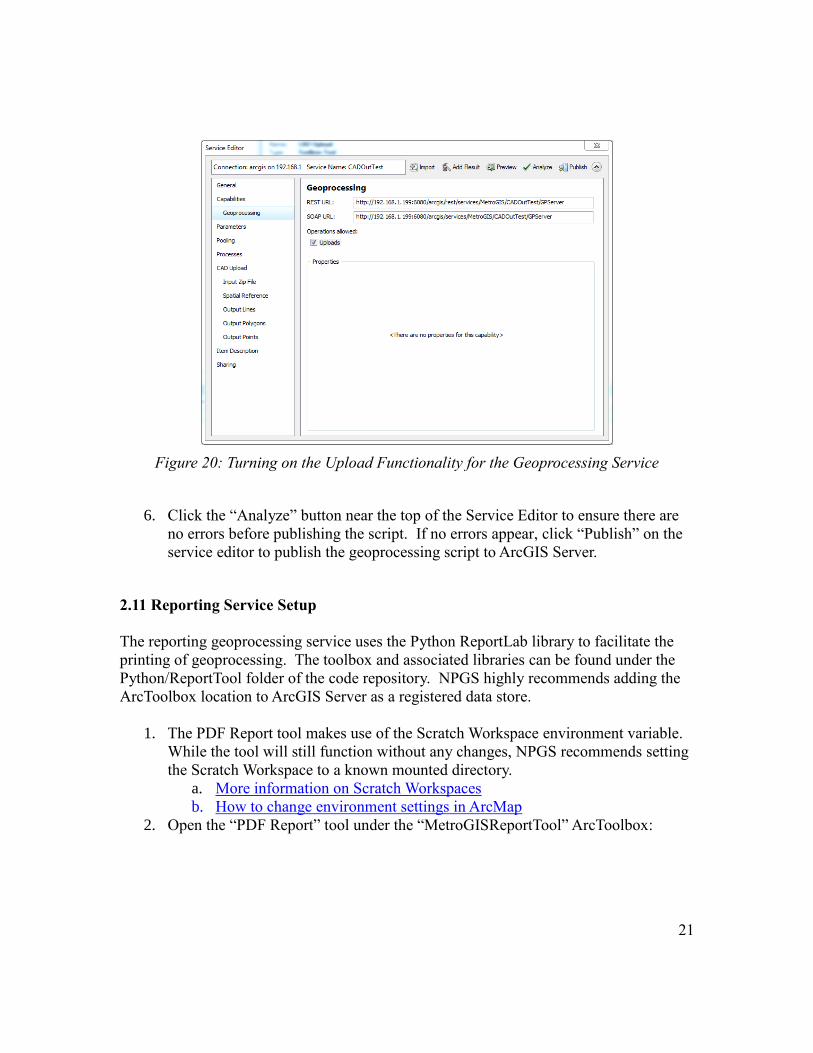
5. Turn on the “Uploads” capabilities under the Geoprocessing tab. This will allow
ArcGIS Server to use uploaded files as part of the input to the geoprocessing
service.
21
Figure 20: Turning on the Upload Functionality for the Geoprocessing Service
6. Click the “Analyze” button near the top of the Service Editor to ensure there are
no errors before publishing the script. If no errors appear, click “Publish” on the
service editor to publish the geoprocessing script to ArcGIS Server.
2.11 Reporting Service Setup
The reporting geoprocessing service uses the Python ReportLab library to facilitate the
printing of geoprocessing. The toolbox and associated libraries can be found under the
Python/ReportTool folder of the code repository. NPGS highly recommends adding the
ArcToolbox location to ArcGIS Server as a registered data store.
1. The PDF Report tool makes use of the Scratch Workspace environment variable.
While the tool will still function without any changes, NPGS recommends setting
the Scratch Workspace to a known mounted directory.
a. More information on Scratch Workspaces
b. How to change environment settings in ArcMap
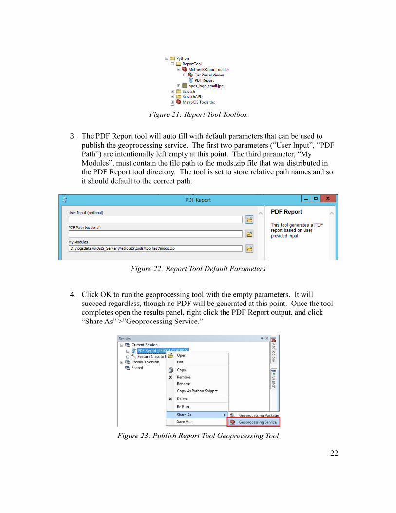
2. Open the “PDF Report” tool under the “MetroGISReportTool” ArcToolbox:
22
Figure 21: Report Tool Toolbox
3. The PDF Report tool will auto fill with default parameters that can be used to
publish the geoprocessing service. The first two parameters (“User Input”, “PDF
Path”) are intentionally left empty at this point. The third parameter, “My
Modules”, must contain the file path to the mods.zip file that was distributed in
the PDF Report tool directory. The tool is set to store relative path names and so
it should default to the correct path.
Figure 22: Report Tool Default Parameters
4. Click OK to run the geoprocessing tool with the empty parameters. It will
succeed regardless, though no PDF will be generated at this point. Once the tool
completes open the results panel, right click the PDF Report output, and click
“Share As” >”Geoprocessing Service.”
Figure 23: Publish Report Tool Geoprocessing Tool
23
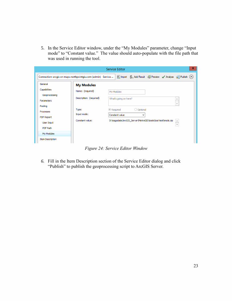
5. In the Service Editor window, under the “My Modules” parameter, change “Input
mode” to “Constant value.” The value should auto-populate with the file path that
was used in running the tool.
Figure 24: Service Editor Window
6. Fill in the Item Description section of the Service Editor dialog and click
“Publish” to publish the geoprocessing script to ArcGIS Server.
24
2.12 Publishing the Address Points Change Table
The address points change table is a required service at Version 3.0. This table facilitates
adds, updates, and deletes of address points during editing. The resulting information is
retrieved by the reporting service when generating reports by date.
1. Export a copy of the “AddressUpdate” table located at “Python/
AddressChange/addressChange.gdb/AddressUpdate.” This table contains the
necessary data model required for adds, updates, and deletes in the Address
Editor.
2. Open ArcMap and add the address points feature class from your SDE database
along with the “AddressUpdate” table that was been migrated to your SDE from
the previous step.
3. Publish this map document as a separate service to ArcGIS Server. The URL for
this service will be added to the application configuration file.
2.13 Application User Interface Configuration
Configuration of the application user interface is setup through the “config/config.js” file.
** It is recommended that the config.js be edited using a programming specific editor
such as NotePad++ (http://notepad-plus-plus.org/) or Sublime Text
(http://www.sublimetext.com/).
Configuration Parameters:
userConfig.metrogisService – URL for dynamic map service containing the data layers
you would like to appear in the application. Must be sure to include at least the
Address Points to this dynamic Map Service.
userConfig.exportAPDataService – URL for the export address point geoprocessing
service
userConfig.saveToPDFService – URL for the export map geoprocessing service
userConfig.CADUploadService – URL for the CAD Upload geoprocessing service
userConfig.parcelLayer – URL for the parcel layer to be used when identifying a location
url – the URL, including layer number, for the parcel layer used in the application
pinField – the parcel PIN field used for searching for parcels in the application
userConfig.addressPointLayer – URL for the address point layer
25
userConfig.addressUpdateService – URL for the Address Change table service. This
table will store the adds, updates, and deletes for address points. This URL is required.
userConfig.addressGridService – Service containing the address grid that will be used
when calculating the hypothetical address number for newly created address points.
userConfig.westAddressAttribute – The west address attribute from the address grid
service.
userConfig.southAddressAttribute – The south address attribute from the address grid
service.
userConfig.eastAddressAttribute – The east address attribute from the address grid
service.
userConfig.minxAddressAttribute – The min X attribute from the address grid service.
userConfig.maxxAddressAttribute – The max X attribute from the address grid service.
userConfig.minyAddressAttribute – The min Y attribute from the address grid service.
userConfig.maxyAddressAttribute – The max Y attribute from the address grid service.
userConfig.eFactorAddressAttribute – The east factor attribute from the address grid
service.
userConfig.sFactorAddressAttribute – The south factor attribute from the address grid
service.
userConfig.geometryService – URL for the geometry service used to calculate the latitude
and longitude values of the address points
userConfig.uniqueTable – URL for the unique ID stand-alone table used to store the
unique ID sequence for the jurisdiction (must be part of the Feature Service allowing
for editing)
userConfig.proxyService – URL for proxy service (required for editing). Please see:
http://help.arcgis.com/en/webapi/javascript/arcgis/help/jshelp_start.htm#jshelp/ags_proxy
.htm for details regarding proxy service setup. Proxy service needs to be hosted on the
same server as the address editor application. At version 3.0 a proxy service and
proxy.config file are included with the application for ease of deployment. The URL
for the ArcGIS Server hosting the map services needs to be added to the proxy.config file.
See example below:
<serverUrl url="http://54.243.223.84/ArcGIS/rest/services/"
matchAll="true"></serverUrl>
<serverUrl url="http://199.21.241.37/ArcGIS/tokens"
matchAll="true"></serverUrl>
<serverUrl url="http://maps2.northpointgis.com/ArcGIS/tokens"
matchAll="true"></serverUrl>

26
<serverUrl url="http://199.21.241.37/rest/services/" username="
serviceUsername” password=”servicePassword”
matchAll="true"></serverUrl>
userConfig.uniqueID – Starting unique ID used for automated ID numbering. Comment
out this line of the config file if the unique ID functionality is not being used.
userConfig.UN – Username for the service referenced in userConfig.metrogisService.
This is required if authentication has been setup for the dynamic or the feature service.
userConfig.shpOutline – The out color and transparency value of the shapes added after
uploading a zipped shapefile. Values are R, G, B values between 0-255 with the last
value being the transparency between 0-1, where 1 is fully opaque.
userConfig.shpInteriorColor - The interior fill color and transparency value of the shapes
added after uploading a zipped shapefile. Values are R, G, B values between 0-255 with
the last value being the transparency between 0-1, where 1 is fully opaque.
userConfig.kmlTransparency – The transparency value for uploaded KML files. Values
range from 0-1 with 1 being 100% opaque.
userConfig.cadLineColor - The line color and transparency value of the line features
added after uploading a zipped CAD file. Values are R, G, B values between 0-255 with
the last value being the transparency between 0-1, where 1 is fully opaque.
userConfig.cadPolygonColor - The polygon color and transparency value of the polygon
features added after uploading a zipped CAD file. Values are R, G, B values between 0-
255 with the last value being the transparency between 0-1, where 1 is fully opaque.
userConfig.cadPointColor - The point color and transparency value of the point features
added after uploading a zipped CAD file. Values are R, G, B values between 0-255 with
the last value being the transparency between 0-1, where 1 is fully opaque.
userConfig.reportFillColor – The fill color that appear on the reports map.
userConfig.reportOutlineColor – The outline color of the selected points that will appear
on the reports.
userConfig.reportPtOutlineWidth – The point outline width that will appear on the
reports.
userConfig.reportPtSize – The size of the points that will appear in the map on the
reports.
27
userConfig.savePDFtoServer – Specifies whether the reporting service output will be
saved to the server for not (true = YES, false = NO).
userConfig.uniqueField – unique ID field in the address points feature class. Comment
out this line of the config file if the unique ID functionality is not being used.
** See Setting up the Unique ID Functionality section for more information
userConfig.printLayers – Names of layers to appear in the list on the print widget
userConfig.basemapLayers – Array list of basemaps used in the application. See the
notes in the config.js for specifics regarding basemap configuration.
userConfig.addressAuthorities – Address authority configuration specifications
uniqueID – Application unique ID. This MUST match the ‘AddressAuthority’
value in the user authentication table aaName – Address Authority name. This MUST match the name in the
‘aauthority’ field in the address point feature class. name – The name that will appear in the application header on the login page and
the main map page
banner – The relative link to the application header image that will appear on the
login page and the main map page
initialExtent – The initial extent of the application
editableAPLayer – URL for the editable feature service containing the address
points feature class in SDE
attributes – Array of attributes that will appear in the Address Point Information
tab. Fields should be added in the following format:
{
'fieldName': 'anumber',
'label': 'Address Number'
}
** To specify a drop down list for the Address Authority field, add the
‘customField’: ‘customSelect’ attribute to the config file along with the options
item specifying the options that will be available in the drop downlist:
{
'fieldName': 'MUNI_NAME',
'label': 'Municipal Name',
'customField': 'customSelect',
28
options: [
{ abbreviation: 'City of Roseville', name: 'City of Roseville' },
{ abbreviation: 'City of CR, name: 'City of CR' },
{ abbreviation: 'City of Anoka', name: 'City of Anoka' }
]
}
** To specify a large text area for a specific field, add the ‘longText’ attribute to
the attribute config section of the config file:
{
'fieldName': 'COMMENTS',
'label': 'Comments',
'customField':'longText'
}
** NOTE: The following attribute fields need to be present in the APD and
spelled exactly as shown here; ‘updatedate’, ‘edit_org’, ‘longitude’, ‘latitude’, and
‘aauthority.’ These fields are updated automatically through the application.
They DO NOT need to be visible in the attributes editor to be updated
automatically.
refLayers – reference layers specific to individual address authorities. Specify the
necessary information for each layer according to the config file
contactInfo – Contact information that will appear in the footer of the application
informationLink – URL for informational link that will appear in the footer of the
application
projections – The list of projections that will appear in the CAD upload dialog.
Need to ensure the name matches the exact wording from the ArcGIS Desktop
projection dialog box.
reportLogo – The server path to the logo that will appear on the reports. ArcGIS
Server must have access and permissions to this path. This parameter is optional.
outputDirectory – the directory under your ArcGIS Server installed directories
where the report output will be saved. This optional folder specification allows
for saving the output reports to a separate folder that will not be automatically
cleared by ArcGIS Server. If no path is specified the tool will save the report to
the default ArcGIS Server jobs directory.
pdfHeader – The information that appear in the header of each address point
report. This information is required.

29
pdfAttributes – three fields from the address points can be specified to display on
the reports along with the change information. All fields over 3 will be ignored
by the reporting tool.
csvAttributes - three fields from the address points can be specified to display on
the CSV output along with the change information. All fields over 3 will be
ignored by the export to CSV tool.
userConfig.parcelAttributes – The list of attributes that will appear in the parcel
information tab. Specify the field name and label you would like to appear in the
application.
function calcHypoAddFunction - The function that calculates the hypothetical address
location. This application can be modified to fit a different organizations hypothetical
address calculation. Please keep in mind that the output parameters from the hypothetical
address function will need to be east, west, and south address. If you would like to
modify the display of the output or the number of outputs please download the developer
version of the Address Editor and modify the FindHypoAdd function.

30
2.13 Setting up the Unique ID Functionality
If you will be implementing the unique ID functionality the following steps need to be
followed:
1. Specify a starting unique ID value in the config.js file (userConfig.uniqueID)
2. Specify the unique ID field in the config.js file to match the unique ID field in
your APD (userConfig.uniqueField)
3. A personal geodatabase named “IDTrackerTable” was included with the
application code zip file. The ‘IDTracker’ table in this geodatabase needs to be
copied to an SDE Geodatabase and published as a feature service layer.
4. Start editing the table in ArcMap to add a new jurisdiction. In the ‘Jursd_Name’
enter the address authority name. This value MUST match the ‘aauthority’
field in the APD. 5. Enter the ‘max_id’ value. This value can be the same as the config file or
higher. The application uses the higher of the two values to assign to assign a
new unique ID. DO NOT edit this table after initial setup. It will be used to keep
track of the current max id in the APD.
31
3. ADDRESS EDITOR APPLICATION USER INSTRUCTIONS
3.1 Recommended Browsers
The address editor application has been designed to support most modern browsers.
NPGS recommends using one of the following browsers for optimal user experience:
Internet Explorer 9 or 10
Firefox 11.0 or higher
Chrome 18.0 or higher
3.2 Address Editor Application Login and Basic Tools
The address editor application has been designed to edit address point information
specific to a jurisdiction. The following information details how to log in and interact
with the basic address editor functionality.
1. Log into the application using the user name and password provided by your
administrator. If you do not have a username or password, contact your account
administrator.
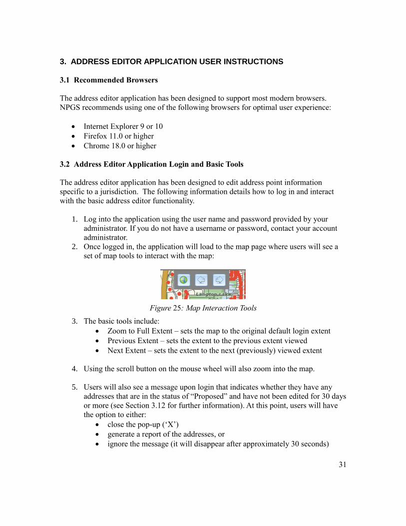
2. Once logged in, the application will load to the map page where users will see a
set of map tools to interact with the map:
Figure 25: Map Interaction Tools
3. The basic tools include:
Zoom to Full Extent – sets the map to the original default login extent
Previous Extent – sets the extent to the previous extent viewed
Next Extent – sets the extent to the next (previously) viewed extent
4. Using the scroll button on the mouse wheel will also zoom into the map.
5. Users will also see a message upon login that indicates whether they have any
addresses that are in the status of “Proposed” and have not been edited for 30 days
or more (see Section 3.12 for further information). At this point, users will have
the option to either:
close the pop-up (‘X’)
generate a report of the addresses, or
ignore the message (it will disappear after approximately 30 seconds)
32
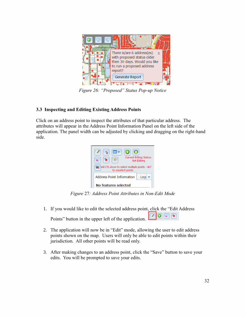
Figure 26: “Proposed” Status Pop-up Notice
3.3 Inspecting and Editing Existing Address Points
Click on an address point to inspect the attributes of that particular address. The
attributes will appear in the Address Point Information Panel on the left side of the
application. The panel width can be adjusted by clicking and dragging on the right-hand
side.
Figure 27: Address Point Attributes in Non-Edit Mode
1. If you would like to edit the selected address point, click the “Edit Address
Points” button in the upper left of the application.
2. The application will now be in “Edit” mode, allowing the user to edit address
points shown on the map. Users will only be able to edit points within their
jurisdiction. All other points will be read only.
3. After making changes to an address point, click the “Save” button to save your
edits. You will be prompted to save your edits.
33
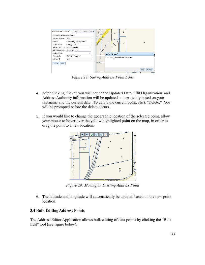
Figure 28: Saving Address Point Edits
4. After clicking “Save” you will notice the Updated Date, Edit Organization, and
Address Authority information will be updated automatically based on your
username and the current date. To delete the current point, click “Delete.” You
will be prompted before the delete occurs.
5. If you would like to change the geographic location of the selected point, allow
your mouse to hover over the yellow highlighted point on the map, in order to
drag the point to a new location.
Figure 29: Moving an Existing Address Point
6. The latitude and longitude will automatically be updated based on the new point
location.
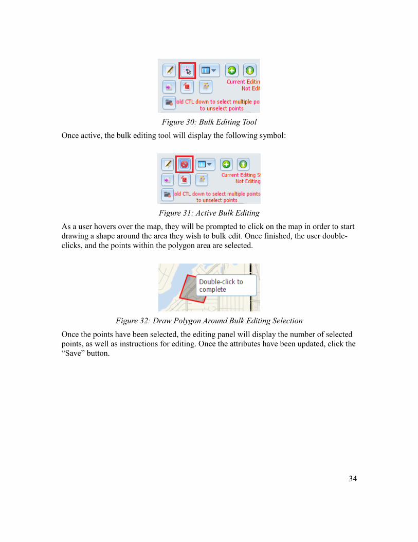
3.4 Bulk Editing Address Points
The Address Editor Application allows bulk editing of data points by clicking the “Bulk
Edit” tool (see figure below).
34
Figure 30: Bulk Editing Tool
Once active, the bulk editing tool will display the following symbol:
Figure 31: Active Bulk Editing
As a user hovers over the map, they will be prompted to click on the map in order to start
drawing a shape around the area they wish to bulk edit. Once finished, the user double-
clicks, and the points within the polygon area are selected.
Figure 32: Draw Polygon Around Bulk Editing Selection
Once the points have been selected, the editing panel will display the number of selected
points, as well as instructions for editing. Once the attributes have been updated, click the
“Save” button.
35
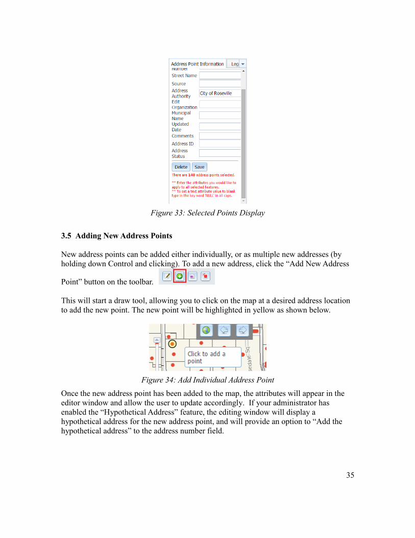
Figure 33: Selected Points Display
3.5 Adding New Address Points
New address points can be added either individually, or as multiple new addresses (by
holding down Control and clicking). To add a new address, click the “Add New Address
Point” button on the toolbar.
This will start a draw tool, allowing you to click on the map at a desired address location
to add the new point. The new point will be highlighted in yellow as shown below.
Figure 34: Add Individual Address Point
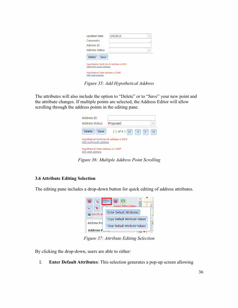
Once the new address point has been added to the map, the attributes will appear in the
editor window and allow the user to update accordingly. If your administrator has
enabled the “Hypothetical Address” feature, the editing window will display a
hypothetical address for the new address point, and will provide an option to “Add the
hypothetical address” to the address number field.
36
Figure 35: Add Hypothetical Address
The attributes will also include the option to “Delete” or to “Save” your new point and
the attribute changes. If multiple points are selected, the Address Editor will allow
scrolling through the address points in the editing pane.
Figure 36: Multiple Address Point Scrolling
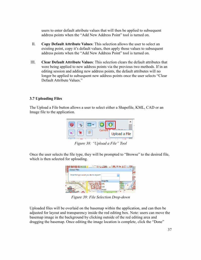
3.6 Attribute Editing Selection
The editing pane includes a drop-down button for quick editing of address attributes.
Figure 37: Attribute Editing Selection
By clicking the drop-down, users are able to either:
I. Enter Default Attributes: This selection generates a pop-up screen allowing
37
users to enter default attribute values that will then be applied to subsequent
address points when the “Add New Address Point” tool is turned on.
II. Copy Default Attribute Values: This selection allows the user to select an
existing point, copy it’s default values, then apply those values to subsequent
address points when the “Add New Address Point” tool is turned on.
III. Clear Default Attribute Values: This selection clears the default attributes that
were being applied to new address points via the previous two methods. If in an
editing session and adding new address points, the default attributes will no
longer be applied to subsequent new address points once the user selects “Clear
Default Attribute Values.”
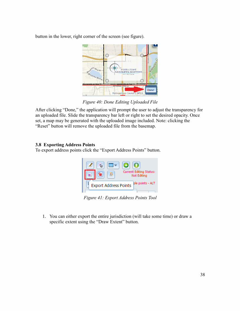
3.7 Uploading Files
The Upload a File button allows a user to select either a Shapefile, KML, CAD or an
Image file to the application.
Figure 38: “Upload a File” Tool
Once the user selects the file type, they will be prompted to “Browse” to the desired file,
which is then selected for uploading.
Figure 39: File Selection Drop-down
Uploaded files will be overlaid on the basemap within the application, and can then be
adjusted for layout and transparency inside the red editing box. Note: users can move the
basemap image in the background by clicking outside of the red editing area and
dragging the basemap. Once editing the image location is complete, click the “Done”
38
button in the lower, right corner of the screen (see figure).
Figure 40: Done Editing Uploaded File
After clicking “Done,” the application will prompt the user to adjust the transparency for
an uploaded file. Slide the transparency bar left or right to set the desired opacity. Once
set, a map may be generated with the uploaded image included. Note: clicking the
“Reset” button will remove the uploaded file from the basemap.
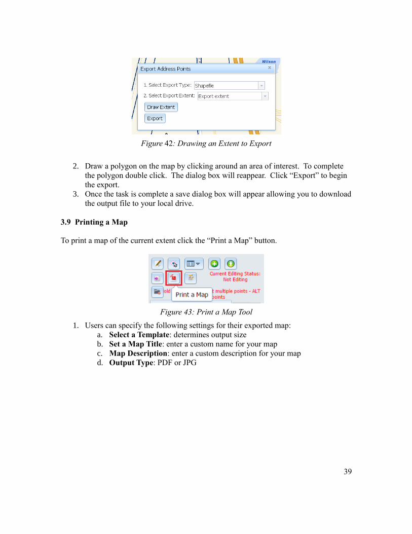
3.8 Exporting Address Points
To export address points click the “Export Address Points” button.
Figure 41: Export Address Points Tool
1. You can either export the entire jurisdiction (will take some time) or draw a
specific extent using the “Draw Extent” button.
39
Figure 42: Drawing an Extent to Export
2. Draw a polygon on the map by clicking around an area of interest. To complete
the polygon double click. The dialog box will reappear. Click “Export” to begin
the export.
3. Once the task is complete a save dialog box will appear allowing you to download
the output file to your local drive.
3.9 Printing a Map
To print a map of the current extent click the “Print a Map” button.
Figure 43: Print a Map Tool
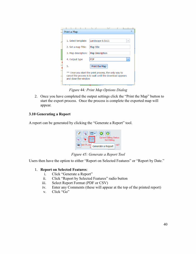
1. Users can specify the following settings for their exported map:
a. Select a Template: determines output size
b. Set a Map Title: enter a custom name for your map
c. Map Description: enter a custom description for your map
d. Output Type: PDF or JPG
40
Figure 44: Print Map Options Dialog
2. Once you have completed the output settings click the “Print the Map” button to
start the export process. Once the process is complete the exported map will
appear.
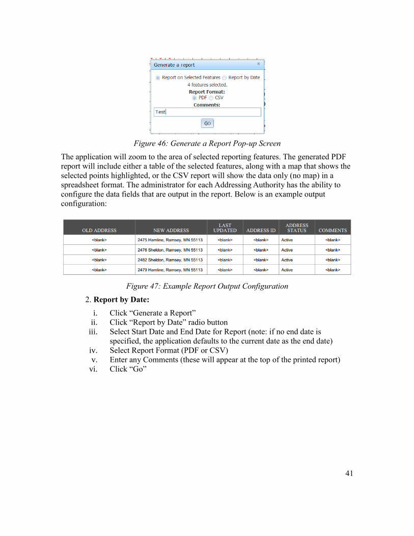
3.10 Generating a Report
A report can be generated by clicking the “Generate a Report” tool.
Figure 45: Generate a Report Tool
Users then have the option to either “Report on Selected Features” or “Report by Date.”
1. Report on Selected Features:
i. Click “Generate a Report”
ii. Click “Report by Selected Features” radio button
iii. Select Report Format (PDF or CSV)
iv. Enter any Comments (these will appear at the top of the printed report)
v. Click “Go”
41
Figure 46: Generate a Report Pop-up Screen
The application will zoom to the area of selected reporting features. The generated PDF
report will include either a table of the selected features, along with a map that shows the
selected points highlighted, or the CSV report will show the data only (no map) in a
spreadsheet format. The administrator for each Addressing Authority has the ability to
configure the data fields that are output in the report. Below is an example output
configuration:
Figure 47: Example Report Output Configuration
2. Report by Date:
i. Click “Generate a Report”
ii. Click “Report by Date” radio button
iii. Select Start Date and End Date for Report (note: if no end date is
specified, the application defaults to the current date as the end date)
iv. Select Report Format (PDF or CSV)
v. Enter any Comments (these will appear at the top of the printed report)
vi. Click “Go”
42
Figure 48: Report by Date Pop-up Screen
The application will zoom to the area of selected reporting features. The generated PDF
report will include either a table of the selected features, along with a map that shows the
selected points highlighted, or the CSV report will show the data only (no map) in a
spreadsheet format. The administrator for each Addressing Authority has the ability to
configure the data fields that are output in the report.
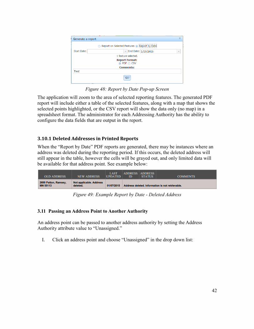
3.10.1 Deleted Addresses in Printed Reports
When the “Report by Date” PDF reports are generated, there may be instances where an
address was deleted during the reporting period. If this occurs, the deleted address will
still appear in the table, however the cells will be grayed out, and only limited data will
be available for that address point. See example below:
Figure 49: Example Report by Date - Deleted Address
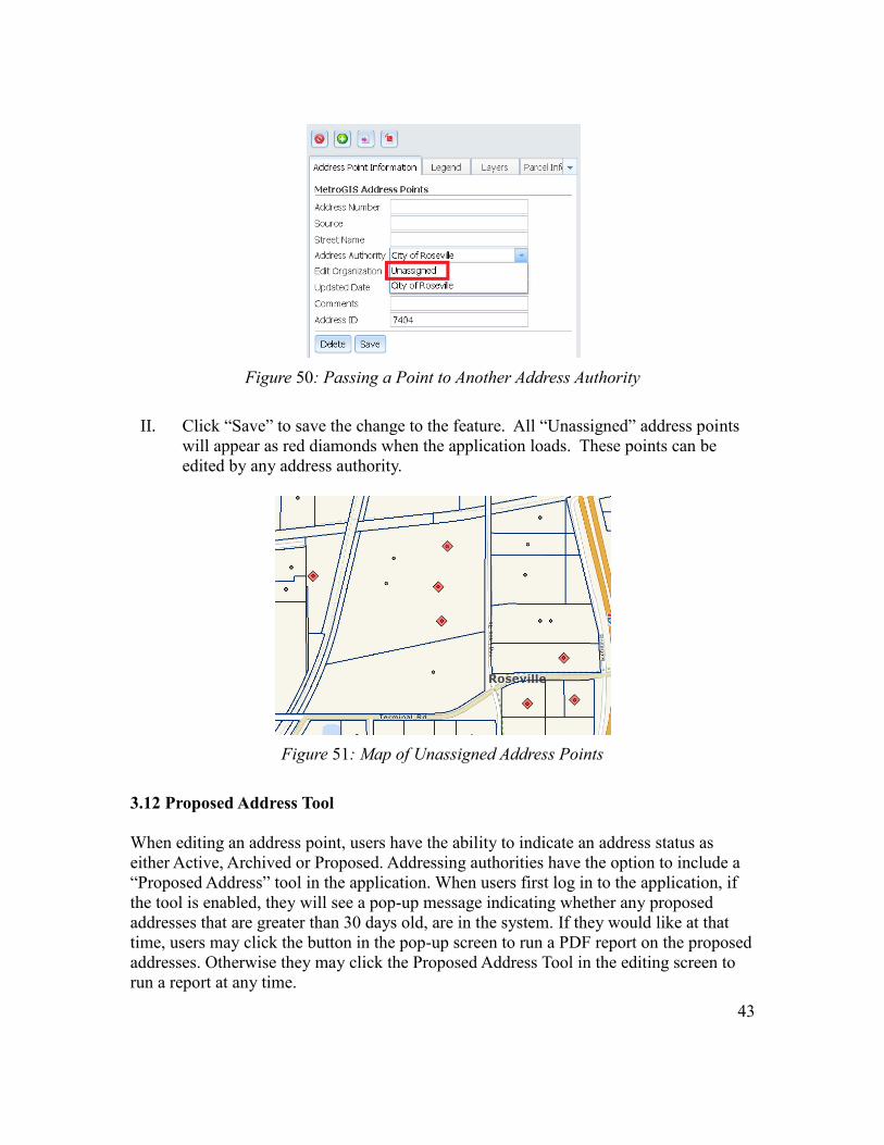
3.11 Passing an Address Point to Another Authority
An address point can be passed to another address authority by setting the Address
Authority attribute value to “Unassigned.”
I. Click an address point and choose “Unassigned” in the drop down list:
43
Figure 50: Passing a Point to Another Address Authority
II. Click “Save” to save the change to the feature. All “Unassigned” address points
will appear as red diamonds when the application loads. These points can be
edited by any address authority.
Figure 51: Map of Unassigned Address Points
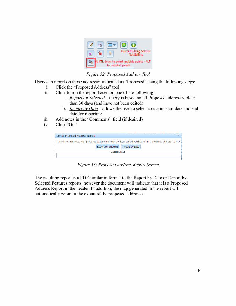
3.12 Proposed Address Tool
When editing an address point, users have the ability to indicate an address status as
either Active, Archived or Proposed. Addressing authorities have the option to include a
“Proposed Address” tool in the application. When users first log in to the application, if
the tool is enabled, they will see a pop-up message indicating whether any proposed
addresses that are greater than 30 days old, are in the system. If they would like at that
time, users may click the button in the pop-up screen to run a PDF report on the proposed
addresses. Otherwise they may click the Proposed Address Tool in the editing screen to
run a report at any time.
44
Figure 52: Proposed Address Tool
Users can report on those addresses indicated as “Proposed” using the following steps:
i. Click the “Proposed Address” tool
ii. Click to run the report based on one of the following:
a. Report on Selected – query is based on all Proposed addresses older
than 30 days (and have not been edited)
b. Report by Date – allows the user to select a custom start date and end
date for reporting
iii. Add notes in the “Comments” field (if desired)
iv. Click “Go”
Figure 53: Proposed Address Report Screen
The resulting report is a PDF similar in format to the Report by Date or Report by
Selected Features reports, however the document will indicate that it is a Proposed
Address Report in the header. In addition, the map generated in the report will
automatically zoom to the extent of the proposed addresses.
45
4.0 OTHER MAP FEATURES
The address editor application has several other features to assist with viewing and
interacting with address points.
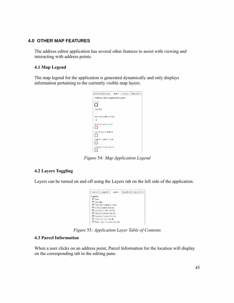
4.1 Map Legend
The map legend for the application is generated dynamically and only displays
information pertaining to the currently visible map layers.
Figure 54: Map Application Legend
4.2 Layers Toggling
Layers can be turned on and off using the Layers tab on the left side of the application.
Figure 55: Application Layer Table of Contents
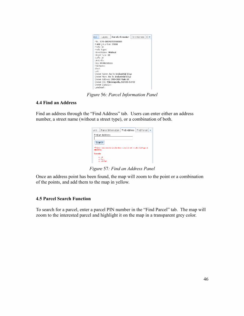
4.3 Parcel Information
When a user clicks on an address point, Parcel Information for the location will display
on the corresponding tab in the editing pane.
46
Figure 56: Parcel Information Panel
4.4 Find an Address
Find an address through the “Find Address” tab. Users can enter either an address
number, a street name (without a street type), or a combination of both.
Figure 57: Find an Address Panel
Once an address point has been found, the map will zoom to the point or a combination
of the points, and add them to the map in yellow.
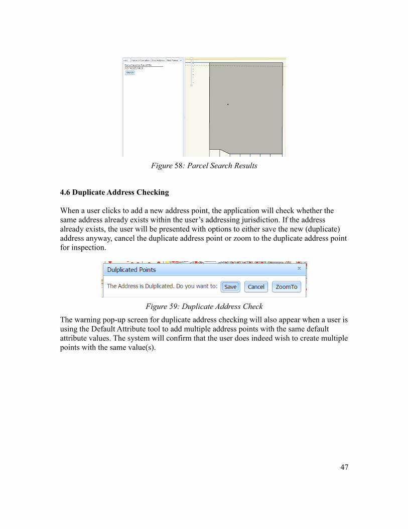
4.5 Parcel Search Function
To search for a parcel, enter a parcel PIN number in the “Find Parcel” tab. The map will
zoom to the interested parcel and highlight it on the map in a transparent grey color.
47
Figure 58: Parcel Search Results
4.6 Duplicate Address Checking
When a user clicks to add a new address point, the application will check whether the
same address already exists within the user’s addressing jurisdiction. If the address
already exists, the user will be presented with options to either save the new (duplicate)
address anyway, cancel the duplicate address point or zoom to the duplicate address point
for inspection.
Figure 59: Duplicate Address Check
The warning pop-up screen for duplicate address checking will also appear when a user is
using the Default Attribute tool to add multiple address points with the same default
attribute values. The system will confirm that the user does indeed wish to create multiple
points with the same value(s).

48
5. ADDRESS EDITOR SUPPORT
Support for the Address Editor can be requested via phone between the following hours:
Monday: 8:30am – 5:00pm CT
Tuesday: 8:30am – 5:00pm CT
Wednesday: 8:30am – 5:00pm CT
Thursday: 8:30am – 5:00pm CT
Friday: 8:30am – 5:00pm CT
Phone number: 218-720-6747
Email support can be requested 24hr/day, 7 days a week, 365 days a year at:
Issues reported to NPGS outside of normal business hours will be responded to within
24hrs of receiving the notice, or by the next business day should the report fall on a
weekend or holiday.
All requests submitted to this email address will be logged in our issue tracking system,
and the proper personnel will be notified.