Uploading Images - bytenet.net Cameras/Nikon WT-3A Wireless... · that wireless transfer is...
14
23 During Upload Do not remove the memory card or disconnect the Ethernet cable during upload. File Names If the destination folder on an ftp server contains files with the same names as images select- ed for upload, the files on the server will be replaced by the images uploaded from the cam- era. Selecting On for Custom Setting d6 (File No. Sequence) during shooting will prevent the camera from creating files with duplicate file names. When uploading files from multiple cameras to the same server, assign each camera its own folder. Loss of Signal Transmission may be interrupted if the signal is lost ( 25). Transmission can be resumed by turning the camera off and then on again, activating the camera exposure meters, or select- ing On for Wireless transmitter > Wireless LAN system once the signal is restored. Uploading Images 1 Press the button to view pictures on the memory card. Display the first picture to be sent in single-image playback or highlight it in the thumbnail list. 2 Press the center of the multi selector while press- ing the button. The image will be marked with a white “send” icon and transmission will begin immediately. During upload, images are marked with a green “sending” icon. Repeat this process to send additional images (pictures will be sent in the order selected). Images that have been successfully uploaded are marked with a blue “sent” icon. Images can be re- sent by pressing the center of the multi selector while pressing the button to change the blue “sent” icon to a white “send” icon.
Transcript of Uploading Images - bytenet.net Cameras/Nikon WT-3A Wireless... · that wireless transfer is...
23
During Upload
Do not remove the memory card or disconnect the Ethernet cable during upload.
File Names
If the destination folder on an ftp server contains fi les with the same names as images select-ed for upload, the fi les on the server will be replaced by the images uploaded from the cam-era. Selecting On for Custom Setting d6 (File No. Sequence) during shooting will prevent the camera from creating fi les with duplicate fi le names. When uploading fi les from multiple cameras to the same server, assign each camera its own folder.
Loss of Signal
Transmission may be interrupted if the signal is lost ( 25). Transmission can be resumed by turning the camera off and then on again, activating the camera exposure meters, or select-ing On for Wireless transmitter > Wireless LAN system once the signal is restored.
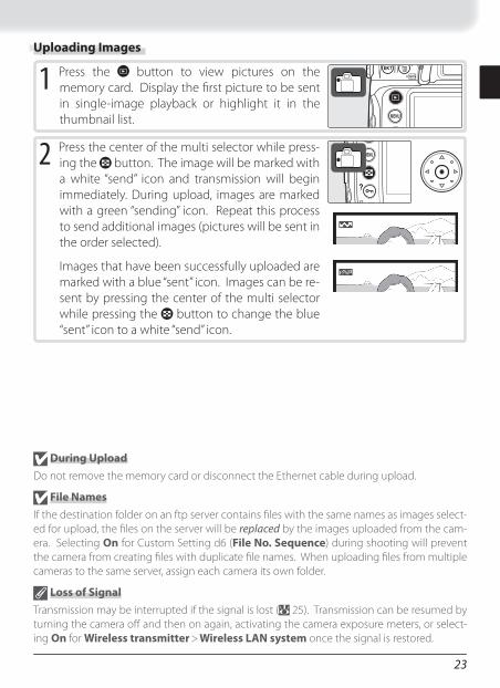
Uploading Images
1 Press the button to view pictures on the memory card. Display the fi rst picture to be sent in single-image playback or highlight it in the thumbnail list.
2 Press the center of the multi selector while press-ing the button. The image will be marked with a white “send” icon and transmission will begin immediately. During upload, images are marked with a green “sending” icon. Repeat this process to send additional images (pictures will be sent in the order selected).
Images that have been successfully uploaded are marked with a blue “sent” icon. Images can be re-sent by pressing the center of the multi selector while pressing the button to change the blue “sent” icon to a white “send” icon.
24
Interrupting TransmissionTo cancel transmission of images marked with a white “send” icon or green “send-ing” icon, select the images during playback and press the center of the multi se-lector while pressing the button. The icon will be removed. Any of the following actions will also interrupt transmission:• Turning the camera off • Choosing Off in the Wireless transmitter > Wireless LAN system menu• Selecting Yes for Wireless transmitter > Settings > Deselect all
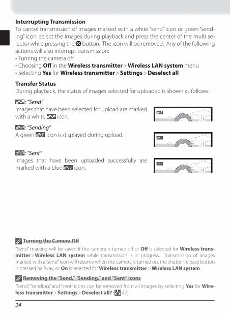
Transfer StatusDuring playback, the status of images selected for uploaded is shown as follows:
: “Send”Images that have been selected for upload are marked with a white icon.
: “Sending”A green icon is displayed during upload.
Turning the Camera Off
“Send” marking will be saved if the camera is turned off or Off is selected for Wireless trans-mitter > Wireless LAN system while transmission is in progress. Transmission of images marked with a “send” icon will resume when the camera is turned on, the shutter-release button is pressed halfway, or On is selected for Wireless transmitter > Wireless LAN system.
Removing the “Send,” “Sending,” and “Sent” Icons
“Send,” “sending,” and “sent” icons can be removed from all images by selecting Yes for Wire-less transmitter > Settings > Deselect all? ( 47).
: “Sent”Images that have been uploaded successfully are marked with a blue icon.
25
Network StatusThe status of the link between the server and the WT-3 is shown by the status LEDs and by the display in the top level of the wireless transmitter menu.
The Status LEDsThe POWER LED lights when the WT-3 is on. Signal qual-ity is shown by the LINK LED: the faster the LED blinks, the better the signal and the faster data can be trans-mitted. The BUSY LED lights while data are being sent.
Status POWER LINK BUSYCamera or exposure meters off , or Off selected for Wireless transmitter > Wireless LAN system
(off ) (off ) (off )
Connecting to host computer or ftp server (on) (on) (off )
Waiting to send data (on) (blinks) (off )
Sending data (on) (blinks) (on)
Connection error (blinks) (off ) (off )
WT-3 hardware malfunction (blinks) (blinks) (blinks)
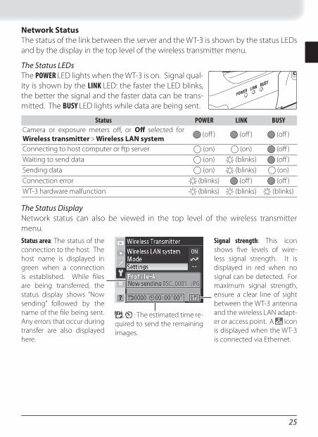
The Status DisplayNetwork status can also be viewed in the top level of the wireless transmitter menu.
Status area: The status of the connection to the host. The host name is displayed in green when a connection is established. While fi les are being transferred, the status display shows “Now sending” followed by the name of the fi le being sent. Any errors that occur during transfer are also displayed here.
, : The estimated time re-quired to send the remaining images.
Signal strength: This icon shows fi ve levels of wire-less signal strength. It is displayed in red when no signal can be detected. For maximum signal strength, ensure a clear line of sight between the WT-3 antenna and the wireless LAN adapt-er or access point. A icon is displayed when the WT-3 is connected via Ethernet.
26
Controlling the Camera: PC ModeIn PC mode, a camera equipped with a WT-3 can be controlled over a wireless net-work from a computer running Nikon Capture 4 version 4.4 or later (available sepa-rately) and photographs saved directly to the computer hard disk instead of the camera memory card. The principal steps are:
Connect to the computer ................................................................... 26–27
The WT-3 Setup Utility must be installed on the host computer. Before connecting to the host, create a host profi le using the WT-3 Setup Utility ( 11–16) and be sure that the host is running.
Connecting to the Computer
Choose PTP
Before connecting the WT-3, set the USB option in the camera setup menu to PTP ( 11).
PictureProject Version 1.6.1 or Later
In PC mode, PictureProject Transfer can be used to transfer pictures to the computer, where they will be cataloged in the PictureProject software supplied with the camera (version 1.6.1 or later required).
1 To access the network via Ethernet, connect the Ethernet cable ( 4). Note that wireless transfer is disabled while an Ethernet cable is connected. Dis-connect the Ethernet cable before accessing a wireless network. Turn the camera off before connecting or disconnecting the Ethernet cable.
2 Turn the camera on.
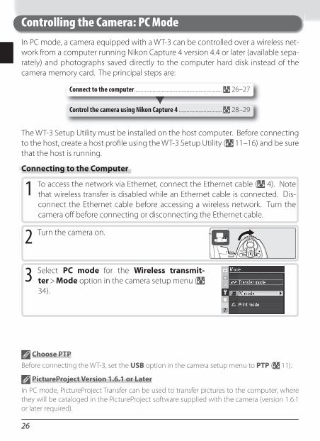
3 Select PC mode for the Wireless transmit-ter > Mode option in the camera setup menu ( 34).
Control the camera using Nikon Capture 4 ................................. 28–29
27
Viewing Profi le InformationPress the camera button to view information on the selected profi le.
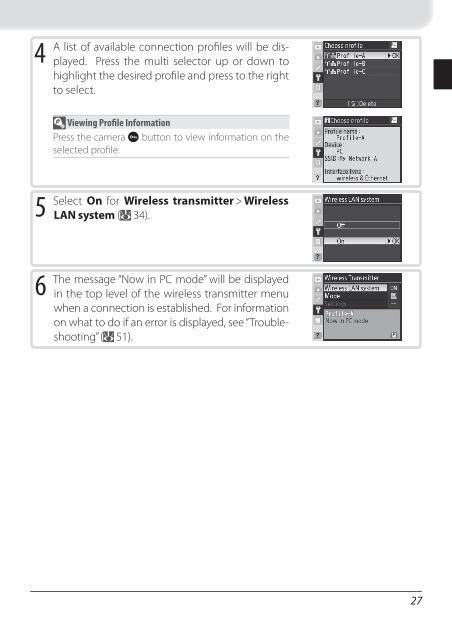
4 A list of available connection profi les will be dis-played. Press the multi selector up or down to highlight the desired profi le and press to the right to select.
5 Select On for Wireless transmitter > Wireless LAN system ( 34).
6 The message “Now in PC mode” will be displayed in the top level of the wireless transmitter menu when a connection is established. For information on what to do if an error is displayed, see “Trouble-shooting” ( 51).
28
Controlling the Camera Using Nikon Capture 4
Ethernet Networks: Do Not Disconnect the Ethernet Cable
Do not disconnect the Ethernet cable while the camera is on.
Wireless Networks: Loss of Signal During Transfer
A loss of signal may interrupt the connection while pictures are being transferred to Nikon Capture 4 Camera Control. If the POWER LED on the WT-3 is blinking ( 29), select Off for the Wireless transmitter > Wireless LAN system option in the camera setup menu and then select On again. Transfer will resume when the connection is re-established. Do not turn the camera off . Transfer can not be resumed once the camera is turned off .
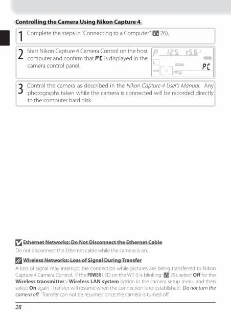
1 Complete the steps in “Connecting to a Computer” ( 26).
2 Start Nikon Capture 4 Camera Control on the host computer and confi rm that is displayed in the camera control panel.
3 Control the camera as described in the Nikon Cap ture 4 User’s Man u al. Any photographs taken while the camera is connected will be recorded directly to the computer hard disk.
29
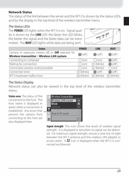
Network StatusThe status of the link between the server and the WT-3 is shown by the status LEDs and by the display in the top level of the wireless transmitter menu.
The Status LEDsThe POWER LED lights when the WT-3 is on. Signal qual-ity is shown by the LINK LED: the faster the LED blinks, the better the signal and the faster data can be trans-mitted. The BUSY LED lights while data are being sent.
Status POWER LINK BUSYCamera or exposure meters off , or Off selected for Wireless transmitter > Wireless LAN system
(off ) (off ) (off )
Connecting to computer (on) (on) (off )Waiting for connection (on) (blinks) (off )Connected; camera control possible (on) (blinks) (on)Connection error (blinks) (off ) (off )WT-3 hardware malfunction (blinks) (blinks) (blinks)
The Status DisplayNetwork status can also be viewed in the top level of the wireless transmitter menu.
Status area: The status of the connection to the host. The host name is displayed in green when a connection is established. Any errors that prevent the camera from connecting to the host are also displayed here.
Signal strength: This icon shows fi ve levels of wireless signal strength. It is displayed in red when no signal can be detect-ed. For maximum signal strength, ensure a clear line of sight between the WT-3 antenna and the wireless LAN adapter or access point. A icon is displayed when the WT-3 is con-nected via Ethernet.
30
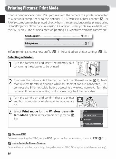
Printing Pictures: Print ModeChoose print mode to print JPEG pictures from the camera to a printer connected to a network computer or to the optional PD-10 wireless printer adapter ( 32). RAW pictures can not be printed directly from the camera, but can be printed using PictureProject or Nikon Capture version 4.4 or later. Index prints are available with the PD-10 only. The principal steps in printing JPEG pictures from the camera are:
Print pictures .................................................................................................. 31
Select a printer ..................................................................................... 30–31
Before printing, create a host profi le ( 11–16) and adjust printer settings ( 17).
Selecting a Printer
1 Turn the camera off and insert the memory card containing the pictures to be printed.
2 To access the network via Ethernet, connect the Ethernet cable ( 4). Note that wireless transfer is disabled while an Ethernet cable is connected. Dis-connect the Ethernet cable before accessing a wireless network. Turn the camera off before connecting or disconnecting the Ethernet cable.
3 Turn the camera on and confi rm that the printer and host computer or wireless printer adapter are on.
4 Select Print mode for the Wireless transmit-ter > Mode option in the camera setup menu ( 34).
Choose PTP
Before connecting the WT-3, set the USB option in the camera setup menu to PTP ( 11).
Use a Reliable Power Source
Be sure the camera battery is fully charged or use an EH-6 AC adapter (available separately).
31
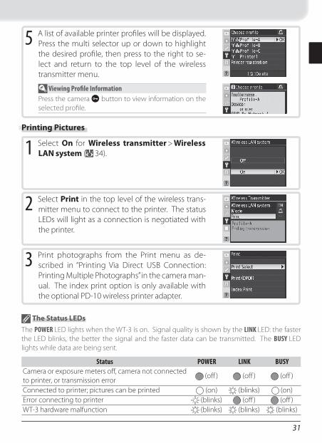
5 A list of available printer profi les will be displayed. Press the multi selector up or down to highlight the desired profi le, then press to the right to se-lect and return to the top level of the wireless transmitter menu.
Viewing Profi le InformationPress the camera button to view information on the selected profi le.
1 Select On for Wireless transmitter > Wireless LAN system ( 34).
2 Select Print in the top level of the wireless trans-mitter menu to connect to the printer. The status LEDs will light as a connection is negotiated with the printer.
3 Print photographs from the Print menu as de-scribed in “Printing Via Direct USB Connection: Printing Multiple Photographs” in the camera man-ual. The index print option is only available with the optional PD-10 wireless printer adapter.
Printing Pictures
The Status LEDs
The POWER LED lights when the WT-3 is on. Signal quality is shown by the LINK LED: the faster the LED blinks, the better the signal and the faster data can be transmitted. The BUSY LED lights while data are being sent.
Status POWER LINK BUSYCamera or exposure meters off , camera not connected to printer, or transmission error
(off ) (off ) (off )
Connected to printer; pictures can be printed (on) (blinks) (on)Error connecting to printer (blinks) (off ) (off )WT-3 hardware malfunction (blinks) (blinks) (blinks)
32
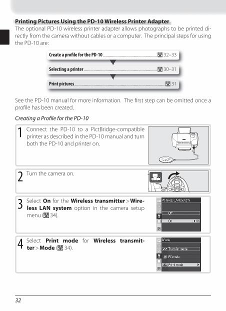
Printing Pictures Using the PD-10 Wireless Printer AdapterThe optional PD-10 wireless printer adapter allows photographs to be printed di-rectly from the camera without cables or a computer. The principal steps for using the PD-10 are:
Create a profi le for the PD-10 .......................................................... 32–33
See the PD-10 manual for more information. The fi rst step can be omitted once a profi le has been created.
Creating a Profi le for the PD-10
Print pictures .................................................................................................. 31
Selecting a printer ............................................................................... 30–31
1 Connect the PD-10 to a PictBridge-compatible printer as described in the PD-10 manual and turn both the PD-10 and printer on.
2 Turn the camera on.
3 Select On for the Wireless transmitter > Wire-less LAN system option in the camera setup menu ( 34).
4 Select Print mode for Wireless transmit-ter > Mode ( 34).
33
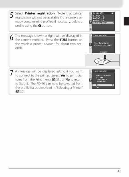
5 Select Printer registration. Note that printer registration will not be available if the camera al-ready contains nine profi les; if necessary, delete a profi le using the button.
7 A message will be displayed asking if you want to connect to the printer. Select Yes to print pic-tures from the Print menu ( 31), or No to return to Step 5. The PD-10 can now be selected from the profi le list as described in “Selecting a Printer” ( 30).
6 The message shown at right will be displayed in the camera monitor. Press the START button on the wireless printer adapter for about two sec-onds.
34
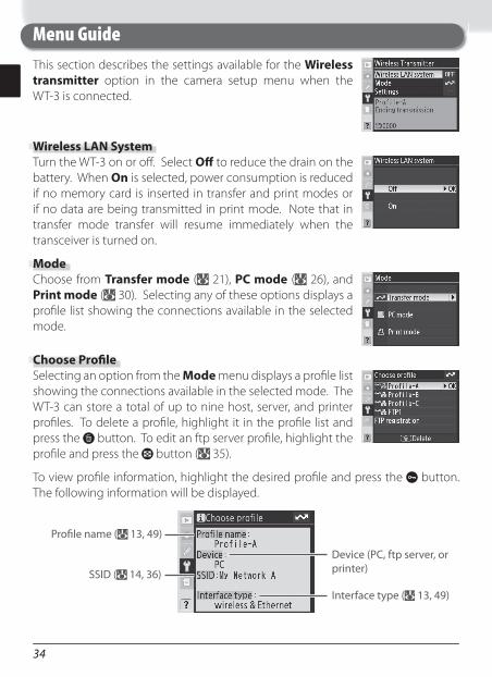
This section describes the settings available for the Wireless transmitter option in the camera setup menu when the WT-3 is connected.
Menu Guide
Wireless LAN SystemTurn the WT-3 on or off . Select Off to reduce the drain on the battery. When On is selected, power consumption is reduced if no memory card is inserted in transfer and print modes or if no data are being transmitted in print mode. Note that in transfer mode transfer will resume immediately when the transceiver is turned on.
ModeChoose from Transfer mode ( 21), PC mode ( 26), and Print mode ( 30). Selecting any of these options displays a profi le list showing the connections available in the selected mode.
Choose Profi leSelecting an option from the Mode menu displays a profi le list showing the connections available in the selected mode. The WT-3 can store a total of up to nine host, server, and printer profi les. To delete a profi le, highlight it in the profi le list and press the button. To edit an ftp server profi le, highlight the profi le and press the button ( 35).
To view profi le information, highlight the desired profi le and press the button. The following information will be displayed.
Device (PC, ftp server, or printer)SSID ( 14, 36)
Interface type ( 13, 49)
Profi le name ( 13, 49)
35
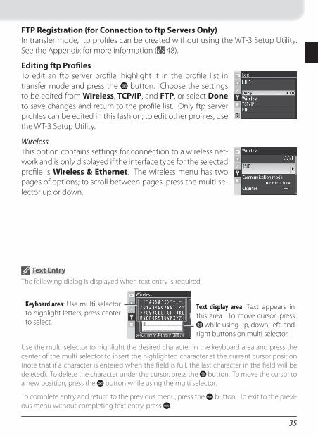
FTP Registration (for Connection to ftp Servers Only)In transfer mode, ftp profi les can be created without using the WT-3 Setup Utility. See the Appendix for more information ( 48).
Editing ftp Profi lesTo edit an ftp server profi le, highlight it in the profi le list in transfer mode and press the button. Choose the settings to be edited from Wireless, TCP/IP, and FTP, or select Done to save changes and return to the profi le list. Only ftp server profi les can be edited in this fashion; to edit other profi les, use the WT-3 Setup Utility.
WirelessThis option contains settings for connection to a wireless net-work and is only displayed if the interface type for the selected profi le is Wireless & Ethernet. The wireless menu has two pages of options; to scroll between pages, press the multi se-lector up or down.
Text Entry
The following dialog is displayed when text entry is required.
Keyboard area: Use multi selector to highlight letters, press center to select.
Text display area: Text appears in this area. To move cursor, press
while using up, down, left, and right buttons on multi selector.
Use the multi selector to highlight the desired character in the keyboard area and press the center of the multi selector to insert the highlighted character at the current cursor position (note that if a character is entered when the fi eld is full, the last character in the fi eld will be deleted). To delete the character under the cursor, press the button. To move the cursor to a new position, press the button while using the multi selector.
To complete entry and return to the previous menu, press the button. To exit to the previ-ous menu without completing text entry, press .
36
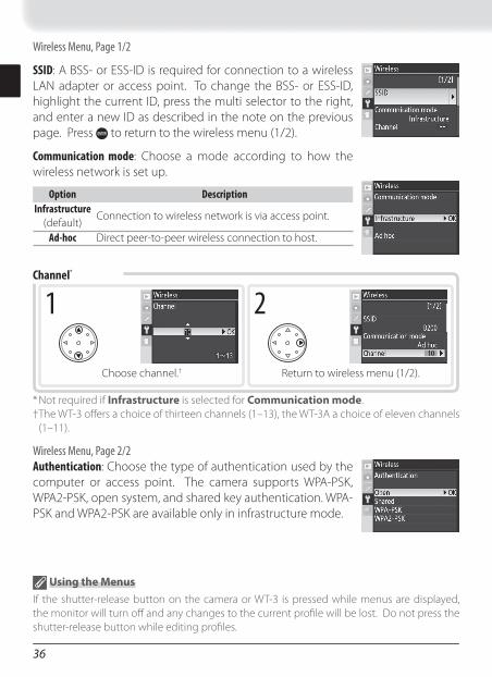
Wireless Menu, Page 1/2
SSID: A BSS- or ESS-ID is required for connection to a wireless LAN adapter or access point. To change the BSS- or ESS-ID, highlight the current ID, press the multi selector to the right, and enter a new ID as described in the note on the previous page. Press to return to the wireless menu (1/2).
Communication mode: Choose a mode according to how the wireless network is set up.
Option DescriptionInfrastructure
(default)Connection to wireless network is via access point.
Ad-hoc Direct peer-to-peer wireless connection to host.
* Not required if Infrastructure is selected for Communication mode.† The WT-3 off ers a choice of thirteen channels (1–13), the WT-3A a choice of eleven channels
(1–11).
Wireless Menu, Page 2/2Authentication: Choose the type of authentication used by the computer or access point. The camera supports WPA-PSK, WPA2-PSK, open system, and shared key authentication. WPA-PSK and WPA2-PSK are available only in infrastructure mode.
Channel *
1
Choose channel. †
2
Return to wireless menu (1/2).
Using the Menus
If the shutter-release button on the camera or WT-3 is pressed while menus are displayed, the monitor will turn off and any changes to the current profi le will be lost. Do not press the shutter-release button while editing profi les.