Upgrades at the NASA Langley Research Center National Transonic Facility · 2013-04-10 · NASA...
11
American Institute of Aeronautics and Astronautics 1 Upgrades at the NASA Langley Research Center National Transonic Facility Roman W. Paryz 1 NASA Langley Research Center, Hampton, VA 23681-2199 Several projects have been completed or are nearing completion at the NASA Langley Research Center (LaRC) National Transonic Facility (NTF). The addition of a Model Flow-Control/Propulsion Simulation test capability to the NTF provides a unique, transonic, high-Reynolds number test capability that is well suited for research in propulsion airframe integration studies, circulation control high-lift concepts, powered lift, and cruise separation flow control. A 1992 vintage Facility Automation System (FAS) that performs the control functions for tunnel pressure, temperature, Mach number, model position, safety interlock and supervisory controls was replaced using current, commercially available components. This FAS upgrade also involved a design study for the replacement of the facility Mach measurement system and the development of a software-based simulation model of NTF processes and control systems. The FAS upgrades were validated by a post upgrade verification wind tunnel test. The data acquisition system (DAS) upgrade project involves the design, purchase, build, integration, installation and verification of a new DAS by replacing several early 1990’s vintage computer systems with state of the art hardware/software. This paper provides an update on the progress made in these efforts. See reference 1. Nomenclature ARRA = American Recovery and Reinvestment Act ATP = Aeronautics Test Program ATS = Automatic Test Sequencer °C, C = Degrees Celsius cm = centimeter CDR = Critical Design Review CRM = Common Research Model DAS = Data Acquisition System DDAS = Dynamic Data Acquisition System DOE = Design Of Experiment °F, F = Degrees Fahrenheit FAS = Facility Automation System FOS = Factor Of Safety FRS = Flow Reference System FS = Full Scale ft, ft 2 = feet, square feet g = Gravity HMI = Human Machine Interface Hp = Horsepower HQ = Headquarters Hz, KHz = Hertz, Kilohertz ISR = Independent Systems Review in, in 2 = Inch, Square inches I/O = Input / Output K = thousand Kg = Kilogram KPa, Pa = Kilo Pascal, Pascal LaRC = Langley Research Center lbs = pounds lbs-in = pounds-inch lbs/sec = pounds per second lbm/sec = pounds mass per second LN2 = Liquid Nitrogen m, m 2 = meter, square meters mm, mm 2 = Millimeters, Square millimeters M = million ms = milliseconds F = Micro-Farrad MCV = Multiple Critical Venturi MMS = Mach Measurement System MPA = Model Preparation Area MW = Megawatt N = Newton N2 = Gaseous Nitrogen NF = Normal Force (lbs) N-m = Newton-meter NTF = National Transonic Facility PC = Personal Computer PCS = Process Computing System PDR = Preliminary Design Review PLC = Programmable Logic Controller PM = Pitching Moment (lbs-in) PRTD = Platinum Resistance Temperature Device PSF, psf = pounds per square foot PSI, psi = pounds per square inch Psia, Psig = Pounds per square inch absolute, gage Psia, Psid = Pounds per square inch absolute, differential RCS = Research Computer System RMS = Root Mean Square RPM = Revolutions per Minute sec = second(s) SLATE = Software for Laboratory and Automated Test Environments SMSS = Sidewall Model Support System SOW = Statement Of Work UOH = User Occupancy Hours VFM = Vortex Flow Meter V/s = Volts per second 1 Facility Manager, National Transonic Facility, AIAA Associate Fellow https://ntrs.nasa.gov/search.jsp?R=20120001450 2018-09-06T09:51:18+00:00Z
Transcript of Upgrades at the NASA Langley Research Center National Transonic Facility · 2013-04-10 · NASA...

American Institute of Aeronautics and Astronautics
1
Upgrades at the NASA Langley Research Center National Transonic Facility
Roman W. Paryz1
NASA Langley Research Center, Hampton, VA 23681-2199
Several projects have been completed or are nearing completion at the NASA Langley Research Center (LaRC) National Transonic Facility (NTF). The addition of a Model Flow-Control/Propulsion Simulation test capability to the NTF provides a unique, transonic, high-Reynolds number test capability that is well suited for research in propulsion airframe integration studies, circulation control high-lift concepts, powered lift, and cruise separation flow control. A 1992 vintage Facility Automation System (FAS) that performs the control functions for tunnel pressure, temperature, Mach number, model position, safety interlock and supervisory controls was replaced using current, commercially available components. This FAS upgrade also involved a design study for the replacement of the facility Mach measurement system and the development of a software-based simulation model of NTF processes and control systems. The FAS upgrades were validated by a post upgrade verification wind tunnel test. The data acquisition system (DAS) upgrade project involves the design, purchase, build, integration, installation and verification of a new DAS by replacing several early 1990’s vintage computer systems with state of the art hardware/software. This paper provides an update on the progress made in these efforts. See reference 1.
Nomenclature
ARRA = American Recovery and Reinvestment Act ATP = Aeronautics Test Program ATS = Automatic Test Sequencer °C, C = Degrees Celsius cm = centimeter CDR = Critical Design Review CRM = Common Research Model DAS = Data Acquisition System DDAS = Dynamic Data Acquisition System DOE = Design Of Experiment °F, F = Degrees Fahrenheit FAS = Facility Automation System FOS = Factor Of Safety FRS = Flow Reference System FS = Full Scale ft, ft2 = feet, square feet g = Gravity HMI = Human Machine Interface Hp = Horsepower HQ = Headquarters Hz, KHz = Hertz, Kilohertz ISR = Independent Systems Review in, in2 = Inch, Square inches I/O = Input / Output K = thousand Kg = Kilogram KPa, Pa = Kilo Pascal, Pascal LaRC = Langley Research Center lbs = pounds lbs-in = pounds-inch lbs/sec = pounds per second lbm/sec = pounds mass per second LN2 = Liquid Nitrogen m, m2 = meter, square meters
mm, mm2 = Millimeters, Square millimeters M = million ms = milliseconds F = Micro-Farrad MCV = Multiple Critical Venturi MMS = Mach Measurement System MPA = Model Preparation Area MW = Megawatt N = Newton N2 = Gaseous Nitrogen NF = Normal Force (lbs) N-m = Newton-meter NTF = National Transonic Facility PC = Personal Computer PCS = Process Computing System PDR = Preliminary Design Review PLC = Programmable Logic Controller PM = Pitching Moment (lbs-in) PRTD = Platinum Resistance Temperature Device PSF, psf = pounds per square foot PSI, psi = pounds per square inch Psia, Psig = Pounds per square inch absolute, gage Psia, Psid = Pounds per square inch absolute, differential RCS = Research Computer System RMS = Root Mean Square RPM = Revolutions per Minute sec = second(s) SLATE = Software for Laboratory and Automated Test Environments SMSS = Sidewall Model Support System SOW = Statement Of Work UOH = User Occupancy Hours VFM = Vortex Flow Meter V/s = Volts per second
1 Facility Manager, National Transonic Facility, AIAA Associate Fellow
https://ntrs.nasa.gov/search.jsp?R=20120001450 2018-09-06T09:51:18+00:00Z

American Institute of Aeronautics and Astronautics
2
I. Introduction The National Transonic Facility (NTF) is a fan-driven, closed-circuit, continuous-flow cryogenic pressurized wind tunnel that became operational in 1984 (Fig. 1). The facility has the capability to adjust test conditions to match model size and has independent control of total temperature, pressure, and fan speed to allow isolation and study of pure compressibility (Mach) effects, viscous (Reynolds number) effects, and aero-elastic (dynamic pressure) effects. Combinations of these test parameters can yield Reynolds numbers from 2 to 145 million per foot (6.6 to 475.7 million per meter) (Fig. 2). The test section is approximately 8.2 feet (2.5 meter) by 8.2 feet (2.5 meter) and 25 feet (7.6 meter) long with a cross sectional area of 66.8 ft2 (6.2 m2). The test section has six slots in the ceiling, six slots in the floor, 14 re-entry flaps in the top and bottom walls to prevent the flow from choking the tunnel at near-sonic conditions, and a 6% openness ratio based on the wall surface area (wall divergence set at zero). See reference 2. NTF can be operated using either air or nitrogen as the test medium. During air operations temperature is controlled by a water-fed heat exchanger located in the settling chamber. During nitrogen operations the temperature is controlled by evaporating liquid nitrogen which is dispersed into the tunnel circuit just upstream of the fan through 296 nozzles in 12 bundles at a maximum rate 1,100 lbs/sec (9,680 gallons/sec; 36K liters/sec). 430 tons of LN2 are produced on site per day and stored in two tanks with a total capacity of 3,800 tons (1,150M gallons; 4.4M liters) These two modes provide the ability to operate the tunnel between -250°F (-157°C) and +150°F (+65°C). Thermal insulation that resides inside the pressure shell minimizes energy consumption. Pressure is controlled by two large vent valves connected to the tunnel circuit between turns #3 and #4. The facility can operate from 14.7 psia (101.4KPa) to 133 psia (917.0 KPa) (1 to 9 atmospheres; 1.01 to 9.2 bar) in either medium. The tunnel drive system is powered by a variable speed motor that has variable maximum torque or power output up to 360 RPM. At 360 RPM the maximum power is 135,000 Hp (101 MW) and that maximum power level is maintained up to 600 RPM. The compressor consists of a fixed pitch, single stage, 25-bladed fan with variable inlet guide vanes. For fine Mach number control, the inlet guide vanes are varied to achieve the required compression ratio to maintain the desired Mach number. Temperature can be maintained within ± 0.3°F (0.17°C) for N2 operations or ± 1°F (0.56°C) for air operations; Pressure ± 0.07 psi (482 Pa); Mach no ± 0.001 or better.
The NTF supports testing of stability and control, cruise performance, stall buffet onset, and configuration aerodynamics. The full-span model support system is a circular arc sector that provides an angle-of-attack range of -11.5° to 19.0° at a rate of up to 4° per sec. The strut incorporates a roll drive with a range of -90° to 180° which, in conjunction with the pitch of the strut, is able to provide pitch and yaw data. The normal force load capacity of the strut is 27,000 lbs (120,102 N). Several sting and strut combinations are available for testing of aerodynamic models. The NTF can accommodate various types of internal 6-component strain gage balances. Onboard angle-of-attack accelerometers are available that include thermal conditioning systems for cryogenic operation.
Figure 1. NTF Circuit Schematic
Figure 2. NTF Operating Map
American Institute of Aeronautics and Astronautics
3
The NTF can also conduct semi-span model investigations using the Sidewall Model Support System (SMSS).
The SMSS is installed in the test section wall with the model mounted on the test section horizontal centerline. The SMSS has a ±28° pitch capability and can accommodate external 5-component strain gage balances up to 27,000 lbs (120,102 N) of normal force. The model is attached via adaptive hardware to the balance, which is installed behind the test section wall within an insulated and heated enclosure. The SMSS can also accommodate a dual channel, high pressure air system to support propulsion airframe integration studies, circulation control high-lift concepts, powered lift, and cruise separation flow control.
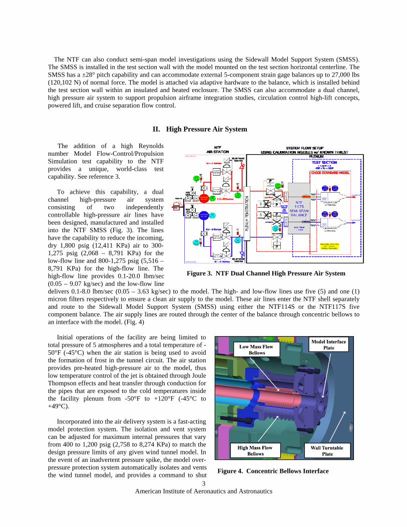
II. High Pressure Air System The addition of a high Reynolds
number Model Flow-Control/Propulsion Simulation test capability to the NTF provides a unique, world-class test capability. See reference 3.
To achieve this capability, a dual
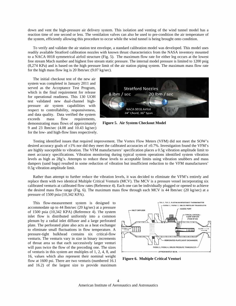
channel high-pressure air system consisting of two independently controllable high-pressure air lines have been designed, manufactured and installed into the NTF SMSS (Fig. 3). The lines have the capability to reduce the incoming, dry 1,800 psig (12,411 KPa) air to 300-1,275 psig (2,068 – 8,791 KPa) for the low-flow line and 800-1,275 psig (5,516 – 8,791 KPa) for the high-flow line. The high-flow line provides 0.1-20.0 lbm/sec (0.05 – 9.07 kg/sec) and the low-flow line delivers 0.1-8.0 lbm/sec (0.05 – 3.63 kg/sec) to the model. The high- and low-flow lines use five (5) and one (1) micron filters respectively to ensure a clean air supply to the model. These air lines enter the NTF shell separately and route to the Sidewall Model Support System (SMSS) using either the NTF114S or the NTF117S five component balance. The air supply lines are routed through the center of the balance through concentric bellows to an interface with the model. (Fig. 4)
Initial operations of the facility are being limited to
total pressure of 5 atmospheres and a total temperature of -50°F (-45°C) when the air station is being used to avoid the formation of frost in the tunnel circuit. The air station provides pre-heated high-pressure air to the model, thus low temperature control of the jet is obtained through Joule Thompson effects and heat transfer through conduction for the pipes that are exposed to the cold temperatures inside the facility plenum from -50°F to +120°F (-45°C to +49°C).
Incorporated into the air delivery system is a fast-acting
model protection system. The isolation and vent system can be adjusted for maximum internal pressures that vary from 400 to 1,200 psig (2,758 to 8,274 KPa) to match the design pressure limits of any given wind tunnel model. In the event of an inadvertent pressure spike, the model over-pressure protection system automatically isolates and vents the wind tunnel model, and provides a command to shut
Figure 3. NTF Dual Channel High Pressure Air System
Figure 4. Concentric Bellows Interface
American Institute of Aeronautics and Astronautics
4
down and vent the high-pressure air delivery system. This isolation and venting of the wind tunnel model has a reaction time of one second or less. The ventilation valves can also be used to pre-condition the air temperature of the system, efficiently allowing this procedure to occur while the wind tunnel is being brought onto condition.
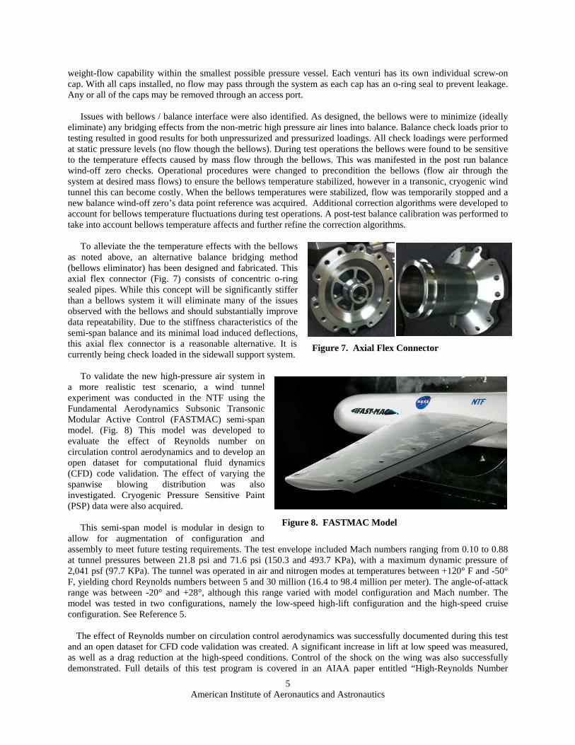
To verify and validate the air station test envelope, a standard calibration model was developed. This model uses
readily available Stratford calibration nozzles with known thrust characteristics from the NASA inventory mounted to a NACA 0018 symmetrical airfoil structure (Fig. 5). The maximum flow rate for either leg occurs at the lowest free stream Mach number and highest free stream static pressure. The internal model pressure is limited to 1200 psig (8,274 KPa) and is based on the high pressure limit of the air station piping system. The maximum mass flow rate for the high mass flow leg is 20 lbm/sec (9.07 kg/sec).
The initial checkout test of the new air
system was completed in January 2011 and served as the Acceptance Test Program, which is the final requirement for release for operational readiness. This 130 UOH test validated new dual-channel high-pressure air system capabilities with respect to controllability, responsiveness, and data quality. Data verified the system exceeds mass flow requirements, demonstrating mass flows of approximately 9 and 23 lbm/sec (4.08 and 10.43 kg/sec) for the low- and high-flow lines respectively.
Testing identified issues that required improvement. The Vortex Flow Meters (VFM) did not meet the SOW’s
desired accuracy goals of ±1% nor did they meet the calibrated accuracies of ±0.7%. Investigation found the VFM’s are highly susceptible to vibration. The VFM manufacturers’ specification places a 0.5g vibration amplitude limit to meet accuracy specifications. Vibration monitoring during typical system operations identified system vibration levels as high as 28g’s. Attempts to reduce these levels to acceptable limits using vibration snubbers and mass dampers (sand bags) resulted in some reduction of vibration but insufficient reduction to the VFM manufacturers’ 0.5g vibration amplitude limit.
Rather than attempt to further reduce the vibration levels, it was decided to eliminate the VFM’s entirely and
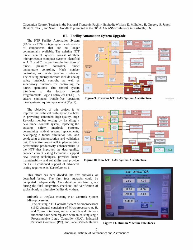
replace them with two identical Multiple Critical Venturis (MCV). The MCV is a pressure vessel incorporating six calibrated venturis at calibrated flow rates (Reference 4). Each one can be individually plugged or opened to achieve the desired mass flow range (Fig. 6). The maximum mass flow through each MCV is 44 lbm/sec (20 kg/sec) at a pressure of 1500 psia (10,342 KPA).
This flow-measurement system is designed to
accommodate up to 44 lbm/sec (20 kg/sec) at a pressure of 1500 psia (10,342 KPA) (Reference 4). The system inlet flow is distributed uniformly into a common plenum by a radial inlet diffuser and a large perforated plate. The perforated plate also acts as a heat exchanger to eliminate small fluctuations in flow temperature. A pressure-tight bulkhead contains six critical-flow venturis. The venturis vary in size in binary increments of throat area so that each successively larger venturi will pass twice the flow of the preceding one. The sizes of venturis in this system are multiples of 1, 2, 4, 8, and 16, values which also represent their nominal weight flow at 1600 psi. There are two venturis (numbered 16.1 and 16.2) of the largest size to provide maximum
Figure 5. Air System Checkout Model
Figure 6. Multiple Critical Venturi
American Institute of Aeronautics and Astronautics
5
weight-flow capability within the smallest possible pressure vessel. Each venturi has its own individual screw-on cap. With all caps installed, no flow may pass through the system as each cap has an o-ring seal to prevent leakage. Any or all of the caps may be removed through an access port.
Issues with bellows / balance interface were also identified. As designed, the bellows were to minimize (ideally
eliminate) any bridging effects from the non-metric high pressure air lines into balance. Balance check loads prior to testing resulted in good results for both unpressurized and pressurized loadings. All check loadings were performed at static pressure levels (no flow though the bellows). During test operations the bellows were found to be sensitive to the temperature effects caused by mass flow through the bellows. This was manifested in the post run balance wind-off zero checks. Operational procedures were changed to precondition the bellows (flow air through the system at desired mass flows) to ensure the bellows temperature stabilized, however in a transonic, cryogenic wind tunnel this can become costly. When the bellows temperatures were stabilized, flow was temporarily stopped and a new balance wind-off zero’s data point reference was acquired. Additional correction algorithms were developed to account for bellows temperature fluctuations during test operations. A post-test balance calibration was performed to take into account bellows temperature affects and further refine the correction algorithms.
To alleviate the the temperature effects with the bellows
as noted above, an alternative balance bridging method (bellows eliminator) has been designed and fabricated. This axial flex connector (Fig. 7) consists of concentric o-ring sealed pipes. While this concept will be significantly stiffer than a bellows system it will eliminate many of the issues observed with the bellows and should substantially improve data repeatability. Due to the stiffness characteristics of the semi-span balance and its minimal load induced deflections, this axial flex connector is a reasonable alternative. It is currently being check loaded in the sidewall support system.
To validate the new high-pressure air system in
a more realistic test scenario, a wind tunnel experiment was conducted in the NTF using the Fundamental Aerodynamics Subsonic Transonic Modular Active Control (FASTMAC) semi-span model. (Fig. 8) This model was developed to evaluate the effect of Reynolds number on circulation control aerodynamics and to develop an open dataset for computational fluid dynamics (CFD) code validation. The effect of varying the spanwise blowing distribution was also investigated. Cryogenic Pressure Sensitive Paint (PSP) data were also acquired.
This semi-span model is modular in design to
allow for augmentation of configuration and assembly to meet future testing requirements. The test envelope included Mach numbers ranging from 0.10 to 0.88 at tunnel pressures between 21.8 psi and 71.6 psi (150.3 and 493.7 KPa), with a maximum dynamic pressure of 2,041 psf (97.7 KPa). The tunnel was operated in air and nitrogen modes at temperatures between +120° F and -50° F, yielding chord Reynolds numbers between 5 and 30 million (16.4 to 98.4 million per meter). The angle-of-attack range was between -20° and +28°, although this range varied with model configuration and Mach number. The model was tested in two configurations, namely the low-speed high-lift configuration and the high-speed cruise configuration. See Reference 5.
The effect of Reynolds number on circulation control aerodynamics was successfully documented during this test and an open dataset for CFD code validation was created. A significant increase in lift at low speed was measured, as well as a drag reduction at the high-speed conditions. Control of the shock on the wing was also successfully demonstrated. Full details of this test program is covered in an AIAA paper entitled “High-Reynolds Number
Figure 7. Axial Flex Connector
Figure 8. FASTMAC Model
American Institute of Aeronautics and Astronautics
6
Circulation Control Testing in the National Transonic Facility (Invited); William E. Milholen, II, Gregory S. Jones, David T. Chan , and Scott L. Goodliff” presented at the 50th AIAA ASM conference in Nashville, TN.
III. Facility Automation System Upgrade The NTF Facility Automation System
(FAS) is a 1992 vintage system and consists of components that are no longer commercially available. The existing NTF tunnel control systems consist of three microprocessor computer systems identified as A, B, and C that perform the functions of tunnel pressure controller, tunnel temperature controller, Mach number controller, and model position controller. The existing microprocessors include analog safety interlock controls, as well as supervisory functions for controlling the tunnel operations. This control system interfaces to the facility through Programmable Logic Controllers (PLC). To ensure continued trouble-free operation these systems require replacement (Fig. 9).
The objective of this project is to improve the technical viability of the NTF in providing continued high-quality, high Reynolds number testing by installing a new tunnel controls system, replacing the existing safety interlock systems, determining critical system replacements, developing a tunnel simulation tool and conducting a demonstration and validation test. This entire project will implement high performance productivity enhancements to the NTF that improves the data quality, enhance current testing techniques, support new testing techniques, provides better maintainability and reliability and provide the LaRC continued support of advanced testing requirements. See reference 6.
This effort has been divided into five subtasks, as
described below. The first four subtasks could be completed independently. Consideration has been given during the final integration, checkout, and verification of each subtask to minimize facility downtime.
Subtask 1: Replace existing NTF Controls System Microprocessors.
The existing NTF Controls System Microprocessors (1992 vintage) consisting of Microprocessors A, B, and C, user interfaces, and all controls and interlock functions have been replaced with an existing single Programmable Logic Controller (PLC), Industrial Personal Computer (PC), and Panel View® Human
Figure 9. Previous NTF FAS System Architecture
Figure 10. New NTF FAS System Architecture
Figure 11. Human Machine Interfaces

American Institute of Aeronautics and Astronautics
7
Machine Interfaces (HMI) (Figs. 10 & 11). No-energy and low energy testing was carried out on all systems (individually) to verify system functionality, operability and responsiveness to support the Independent Systems Review (ISR). The ISR was successfully completed in mid October 2011 leading to high energy integrated (simultaneous) multi-system checkout. Test 212 carried out this testing with a simple bullet-nosed adapter. This test was immediately followed by Test 209 (see Subtask 5).
Subtask 2: Replace existing NTF Programmable Logic Controllers. The existing PLCs A, B, C, and D were upgraded from the Allen-Bradley Series 5 to ControLogix 5000 (Fig. 12). Each existing PLC was replaced one-for-one with a new PLC ControLogix 5000 in order to maintain the current relationship on logic solving, allowing for parallel inputs and series outputs as in the existing operating PLCs. This effort was made extremely simple through the use of a vendor provided interface adapter, which allowed the mating of old Series 5 sockets to the new ControLogix 5000. After the PLCs were exchanged, 21 random system interlock checks were performed to verify system functionality and validate that new system is unchanged in I/O capability and logical function.
Subtask 3: Design Study for Replacement PSI Flow Reference System. The current NTF Flow Reference System (FRS) is a critical data quality measurement device that provides precision absolute and differential pressure measurements that are used in determining the tunnel Mach number. The manufacturer has discontinued the FRS and no longer carries replacement or spare parts. Additionally, they have chosen not to offer a replacement or upgrade system for the FRS. This study has been completed and provides the specifications for a replacement Mach Measurement System (MMS). This system will consist of a primary and back-up units consisting of two different absolute pressure ranges and three different differential pressure ranges each to span the entire operating pressure envelope of the NTF. The objective of this is to increase the Mach number measurement accuracy by at least five (5) fold and reduce annual calibration costs by approximately 50%.
Subtask 4: Software-based Simulation Model of the NTF tunnel processes and control systems. The NTF has complex control systems with strong interactions and dependencies. For example, Mach number control is affected by tunnel pressure, temperature, fan pressure ratio, and whether the tunnel is operating with air or nitrogen as the test gas. Optimization of the current control systems has been limited by the complexity and wide range of facility operational conditions, high operational expenses, risks, and extensive commitments of tunnel operational time. As a result, little new optimization or algorithm development has taken place. A software-based simulation model has been developed and implemented that will allow for this necessary optimization development work without the need to operate the tunnel. MATLAB with its companion simulation package Simulink is the modeling software package selected for the NTF math model. The model was created using MATLAB release 2010a. The facility was divided into five major components; A) NTF Airline Circuit; B) High Pressure Air Supply; C) Ventilation System; D) Liquid Nitrogen System; E) Cooling Water System. Each major component
Figure 12. PLC Replacement
Figure 13. NTF Simulation Control Volumes
American Institute of Aeronautics and Astronautics
8
was further segmented with various control volume segments.
In order to create a reasonably responsive (quick) simulation several simplifying assumptions were made for the simulation. Some of these assumptions are: Each gas media is considered a thermally perfect ideal gas Density, Temperature and Pressure are assumed uniform throughout each control volume. To
capture the axial gradients of the flow from the contraction through the test section to the high-speed diffuser, a combination of two methods were used. The first method was to increase the number of control volumes (Fig. 13) thus reducing the length and volume of the individual sections. The other method was to utilize a 1-D CFD code using the solution-time Conservation Element and Solution Element Method (CESE) for the test section and part of the high speed diffuser.
The ambient temperature and pressure remain constant The tunnel either starts with complete Air or Nitrogen at stated temperature and pressure. The
model does not support transition from Air to Nitrogen operation or vice versa.
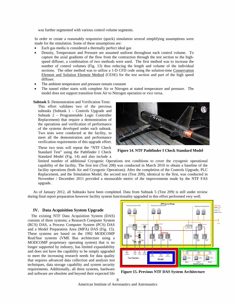
Subtask 5: Demonstration and Verification Tests: This effort validates two of the previous subtasks (Subtask 1 – Controls Upgrade and Subtask 2 – Programmable Logic Controller Replacement) that require a demonstration of the operations and verification of performance of the systems developed under each subtask. Two tests were conducted at the facility, to meet all the demonstration and performance verification requirements of this upgrade effort.
These two tests will repeat the “NTF Check Standard Test” using the Pathfinder I Check Standard Model (Fig. 14) and also include a limited number of additional Cryogenic Operations test conditions to cover the cryogenic operational capability of the facility. The first test (Test 208) was conducted in March 2010 to obtain a baseline of the facility operations (both Air and Cryogenic Operations). After the completion of the Controls Upgrade, PLC Replacement, and the Simulation Model, the second test (Test 209), identical to the first, was conducted in November / December 2011 provided a measurable metric of the improvements made by the NTF FAS upgrade.
As of January 2012, all Subtasks have been completed. Data from Subtask 5 (Test 209) is still under review
during final report preparation however facility system functionality upgraded in this effort performed very well.
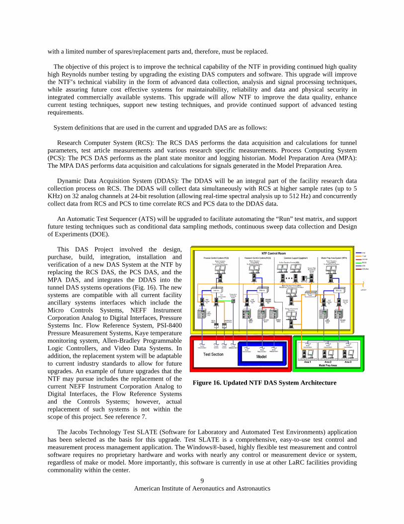
IV. Data Acquisition System Upgrade The existing NTF Data Acquisition System (DAS)
consists of three systems; a Research Computer System (RCS) DAS, a Process Computer System (PCS) DAS and a Model Preparation Area (MPA) DAS (Fig. 15). These systems are based on the 1992 MODCOMP Real/Star systems (VME Bus architecture using a MODCOMP proprietary operating system) that is no longer supported by industry, has limited expandability and does not have the capability to be simply upgraded to meet the increasing research needs for data quality that requires advanced data collection and analysis test techniques, data storage capability and system security requirements. Additionally, all three systems, hardware and software are obsolete and beyond their expected life Figure 15. Previous NTF DAS System Architecture
Figure 14. NTF Pathfinder I Check Standard Model
American Institute of Aeronautics and Astronautics
9
with a limited number of spares/replacement parts and, therefore, must be replaced. The objective of this project is to improve the technical capability of the NTF in providing continued high quality
high Reynolds number testing by upgrading the existing DAS computers and software. This upgrade will improve the NTF’s technical viability in the form of advanced data collection, analysis and signal processing techniques, while assuring future cost effective systems for maintainability, reliability and data and physical security in integrated commercially available systems. This upgrade will allow NTF to improve the data quality, enhance current testing techniques, support new testing techniques, and provide continued support of advanced testing requirements.
System definitions that are used in the current and upgraded DAS are as follows:
Research Computer System (RCS): The RCS DAS performs the data acquisition and calculations for tunnel parameters, test article measurements and various research specific measurements. Process Computing System (PCS): The PCS DAS performs as the plant state monitor and logging historian. Model Preparation Area (MPA): The MPA DAS performs data acquisition and calculations for signals generated in the Model Preparation Area.
Dynamic Data Acquisition System (DDAS): The DDAS will be an integral part of the facility research data
collection process on RCS. The DDAS will collect data simultaneously with RCS at higher sample rates (up to 5 KHz) on 32 analog channels at 24-bit resolution (allowing real-time spectral analysis up to 512 Hz) and concurrently collect data from RCS and PCS to time correlate RCS and PCS data to the DDAS data.
An Automatic Test Sequencer (ATS) will be upgraded to facilitate automating the “Run” test matrix, and support
future testing techniques such as conditional data sampling methods, continuous sweep data collection and Design of Experiments (DOE).
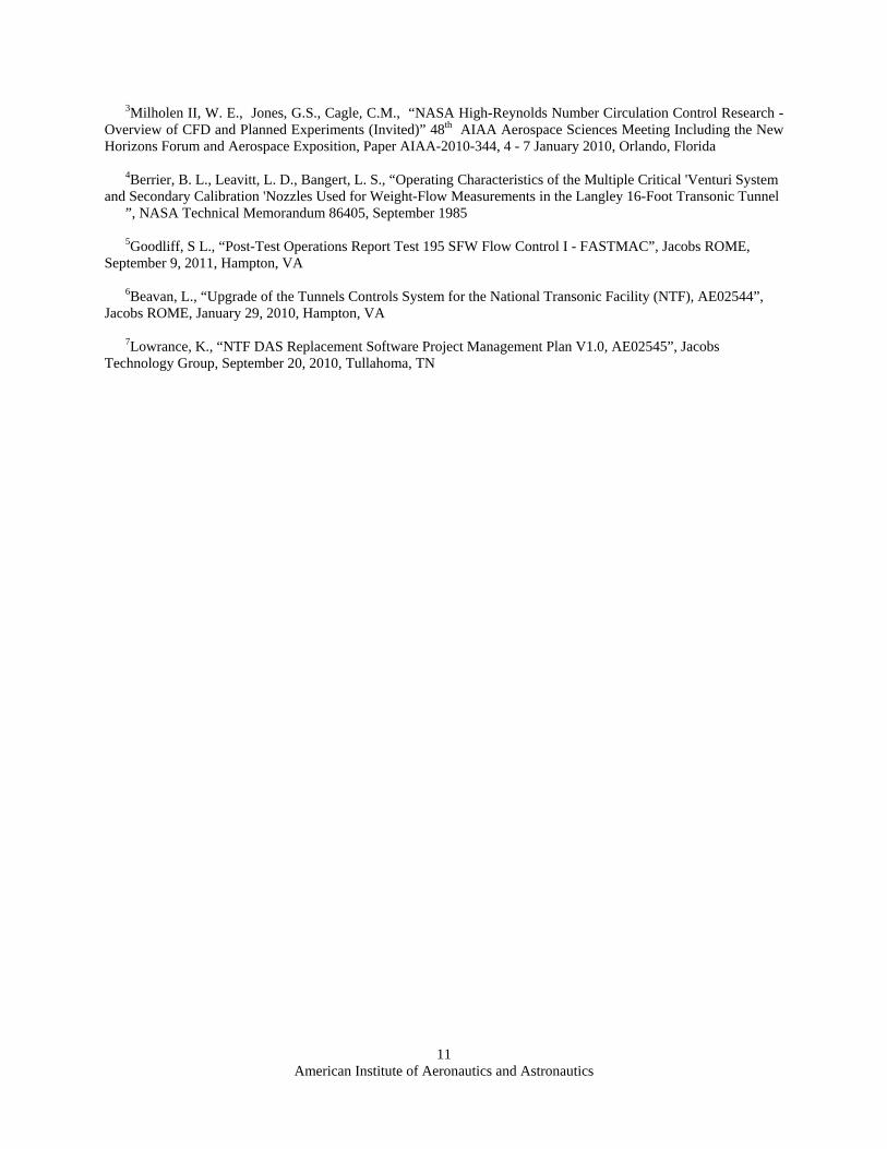
This DAS Project involved the design,
purchase, build, integration, installation and verification of a new DAS System at the NTF by replacing the RCS DAS, the PCS DAS, and the MPA DAS, and integrates the DDAS into the tunnel DAS systems operations (Fig. 16). The new systems are compatible with all current facility ancillary systems interfaces which include the Micro Controls Systems, NEFF Instrument Corporation Analog to Digital Interfaces, Pressure Systems Inc. Flow Reference System, PSI-8400 Pressure Measurement Systems, Kaye temperature monitoring system, Allen-Bradley Programmable Logic Controllers, and Video Data Systems. In addition, the replacement system will be adaptable to current industry standards to allow for future upgrades. An example of future upgrades that the NTF may pursue includes the replacement of the current NEFF Instrument Corporation Analog to Digital Interfaces, the Flow Reference Systems and the Controls Systems; however, actual replacement of such systems is not within the scope of this project. See reference 7.
The Jacobs Technology Test SLATE (Software for Laboratory and Automated Test Environments) application
has been selected as the basis for this upgrade. Test SLATE is a comprehensive, easy-to-use test control and measurement process management application. The Windows®-based, highly flexible test measurement and control software requires no proprietary hardware and works with nearly any control or measurement device or system, regardless of make or model. More importantly, this software is currently in use at other LaRC facilities providing commonality within the center.
Figure 16. Updated NTF DAS System Architecture

American Institute of Aeronautics and Astronautics
10
The NTF DAS Upgrade Project will also replace the current computer systems. Improvements and upgrades will
be by-products of using updated equipment and software. The project is associated with a long term plan to provide a common hardware/software platform for staff sharing between other test facilities for commonality across LaRC. The NTF DAS is the primary system that acquires, processes, monitors, displays, stores, and provides final data products for the NTF wind tunnel. Other auxiliary systems such test article control systems, video systems, facility control systems, and in-house or customer-supplied test peculiar data systems that support the testing process also interface with the NTF DAS.
The DAS upgrade approach, system development,
and implementation is being accomplished in five distinct phases. These phases were Phase 1 - Design Study, Phase 2 - Preliminary Design Review (PDR), Phase 3 - Critical Design Review (CDR), Phase 4 - Equipment, Software, & Bench Top Integration, and Phase 5 - Facility Installation. Phases 1-4 have all been successfully completed, and Phase 5 is currently underway (Fig. 17). Facility operations and contractor staff are executing the Installation and Acceptance Testing Plans of the new DAS at the NTF. Additionally, detailed training and training documentation on the operations and maintenance of the new DAS systems is also underway.
This project is on track to be completed by mid-year 2012 and has been funded through the American Recovery
and Reinvestment Act of 2009 (ARRA).
V. Conclusion
The NASA Langley Research Center National Transonic Facility has been engaged in a two year effort to improve the quality and reliability of the National Transonic Facility. These projects represent a more than $12M investment into facility’s systems to ensure that NTF will continue to produce high quality data in a safe, efficient, and cost effective manner to satisfy the NTF’s worldwide customer base.
Disclaimer of Endorsement Neither the U.S. Government nor NASA endorse or recommend any commercial products, processes, or
services. Reference to or appearance of any specific commercial products, processes, or services by trade name, trademark, manufacturer, or otherwise, in NASA materials does not constitute or imply its endorsement, recommendation, or favoring by the U.S. Government or NASA and are presented for reporting purposes only. The views and opinions of the author(s) expressed in this report do not necessarily state or reflect those of the U.S. Government or NASA, and they may not be used for advertising or product endorsement purposes.
References 1Paryz, R. W.., “Selected Major Modifications To The National Transonic Facility,” 49th AIAA Aerospace
Sciences Meeting, Paper AIAA 2011-877, 4 - 7 January 2011, Orlando, Florida 2Bissett, O. W., Hudson, C. M., “Selected Major Modifications To The National Transonic Facility,” 47th AIAA
Aerospace Sciences Meeting, Paper AIAA-2009-419, 5 - 8 January 2009, Orlando, Florida
Figure 17. Updated NTF DAS
American Institute of Aeronautics and Astronautics
11
3Milholen II, W. E., Jones, G.S., Cagle, C.M., “NASA High-Reynolds Number Circulation Control Research - Overview of CFD and Planned Experiments (Invited)” 48th AIAA Aerospace Sciences Meeting Including the New Horizons Forum and Aerospace Exposition, Paper AIAA-2010-344, 4 - 7 January 2010, Orlando, Florida
4Berrier, B. L., Leavitt, L. D., Bangert, L. S., “Operating Characteristics of the Multiple Critical 'Venturi System
and Secondary Calibration 'Nozzles Used for Weight-Flow Measurements in the Langley 16-Foot Transonic Tunnel ”, NASA Technical Memorandum 86405, September 1985 5Goodliff, S L., “Post-Test Operations Report Test 195 SFW Flow Control I - FASTMAC”, Jacobs ROME,
September 9, 2011, Hampton, VA 6Beavan, L., “Upgrade of the Tunnels Controls System for the National Transonic Facility (NTF), AE02544”,
Jacobs ROME, January 29, 2010, Hampton, VA
7Lowrance, K., “NTF DAS Replacement Software Project Management Plan V1.0, AE02545”, Jacobs Technology Group, September 20, 2010, Tullahoma, TN