Upgrade plan of KEKB
29
Y. Ohnishi / KEK Upgrade plan of KEKB from 2012 to 20XX Y. Ohnishi / KEK 2008 January 24-26 Atami, Izu, Japan
-
Upload
keefe-allen -
Category
Documents
-
view
35 -
download
1
description
Upgrade plan of KEKB. from 2012 to 20XX Y. Ohnishi / KEK 2008 January 24-26 Atami, Izu, Japan. What is luminosity ?. Luminosity is defined by: N is a number of events should be observed. We want to increase N to decrease a statistical error. - PowerPoint PPT Presentation
Transcript of Upgrade plan of KEKB
Y. Ohnishi / KEK
Upgrade plan of KEKB
from 2012 to 20XX
Y. Ohnishi / KEK2008 January 24-26
Atami, Izu, Japan
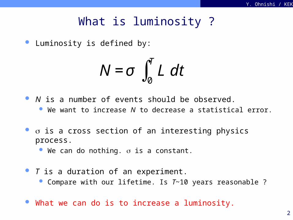
2
Y. Ohnishi / KEK
What is luminosity ?
Luminosity is defined by:
N is a number of events should be observed. We want to increase N to decrease a statistical error.
is a cross section of an interesting physics process. We can do nothing. is a constant.
T is a duration of an experiment. Compare with our lifetime. Is T~10 years reasonable ?
What we can do is to increase a luminosity.
€
N = σ L dt0
T
∫
3
Y. Ohnishi / KEK
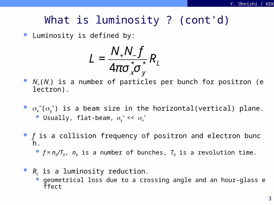
What is luminosity ? (cont'd) Luminosity is defined by:
N+(N-) is a number of particles per bunch for positron (electron).
x*(y
*) is a beam size in the horizontal(vertical) plane. Usually, flat-beam, y
* << x*
f is a collision frequency of positron and electron bunch. f = nb/T0, nb is a number of bunches, T0 is a revolution time.
RL is a luminosity reduction. geometrical loss due to a crossing angle and an hour-glass effect
€
L =N+N− f
4πσ x*σ y
*RL
4
Y. Ohnishi / KEK
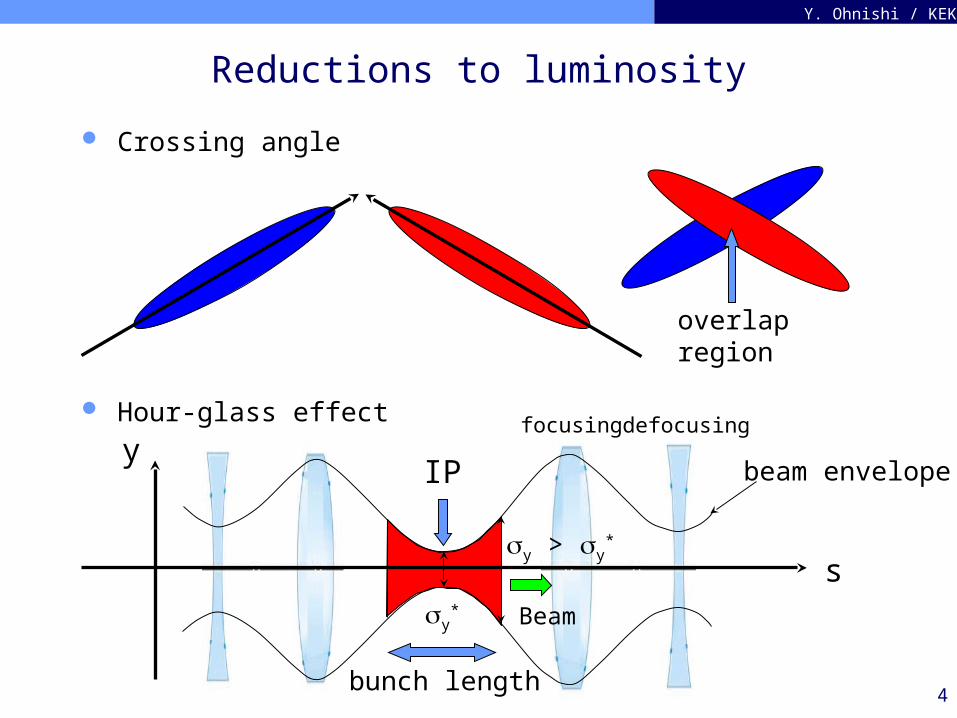
Reductions to luminosity
Crossing angle
Hour-glass effecty
beam envelope
s
IP
bunch length
y*
focusing defocusing
y > y*
overlapregion
Beam
5
Y. Ohnishi / KEK
What limit the luminosity ?
☞ This might be true !
Reduction from the geometrical loss ?
Bunch length, z < y*, where y
* = (yy*)1/2.
Larger impedance in a ring makes bunch length longer. Head-on collision is preferable.
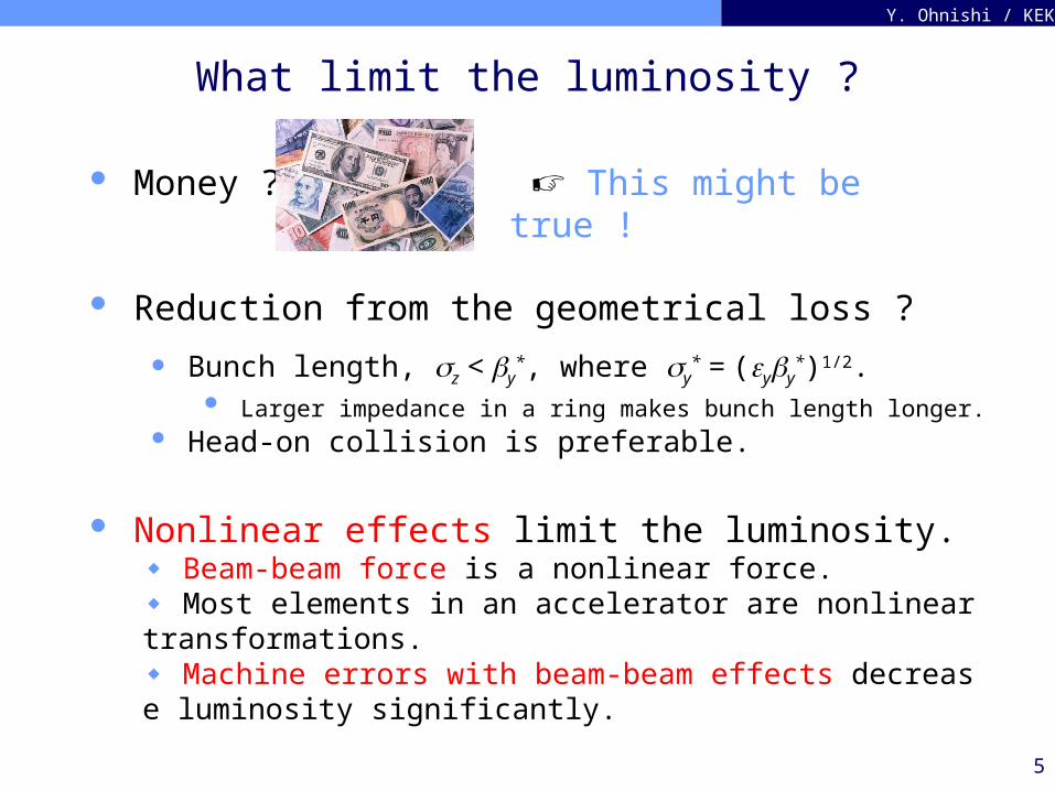
Money ?
Nonlinear effects limit the luminosity.◆ Beam-beam force is a nonlinear force.◆ Most elements in an accelerator are nonlinear transformations.◆ Machine errors with beam-beam effects decrease luminosity significantly.
6
Y. Ohnishi / KEK
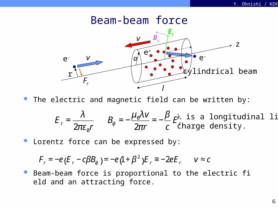
Beam-beam force
The electric and magnetic field can be written by:
Lorentz force can be expressed by:
Beam-beam force is proportional to the electric field and an attracting force.
z
e-e+
v
v
r
a
l
€
E r =λ
2πε0rBϕ = −
μ0λv
2πr= −
β
cE r
€
Fr = −e E r − cβBϕ( ) = −e 1+ β 2( )E r ≅ −2eE r v ≈ c
Fr
is a longitudinal linecharge density.
cylindrical beam
ErB
e-
7
Y. Ohnishi / KEK
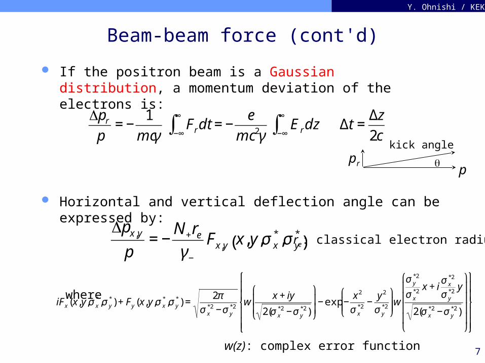
Beam-beam force (cont'd)
If the positron beam is a Gaussian distribution, a momentum deviation of the electrons is:
Horizontal and vertical deflection angle can be expressed by:
where
€
Δpr
p= −
1
mcγFrdt = −
e
mc 2γ−∞
∞
∫ E rdz−∞
∞
∫ Δt =Δz
2c
€
Δpx,y
p= −
N+re
γ−
Fx,y x, y,σ x*,σ y
*( )
€
iFx (x, y,σ x*,σ y
*) + Fy (x,y,σ x*,σ y
*) =2π
σ x*2 −σ y
*2w
x + iy
2(σ x*2 −σ y
*2)
⎛
⎝
⎜ ⎜
⎞
⎠
⎟ ⎟− exp −
x 2
σ x*2
−y 2
σ y*2
⎛
⎝ ⎜ ⎜
⎞
⎠ ⎟ ⎟w
σ y*2
σ x*2
x + iσ x
*2
σ y*2
y
2(σ x*2 −σ y
*2)
⎛
⎝
⎜ ⎜ ⎜ ⎜
⎞
⎠
⎟ ⎟ ⎟ ⎟
⎧
⎨
⎪ ⎪
⎩
⎪ ⎪
⎫
⎬
⎪ ⎪
⎭
⎪ ⎪
w(z): complex error function
re: classical electron radius
ppr
kick angle
8
Y. Ohnishi / KEK
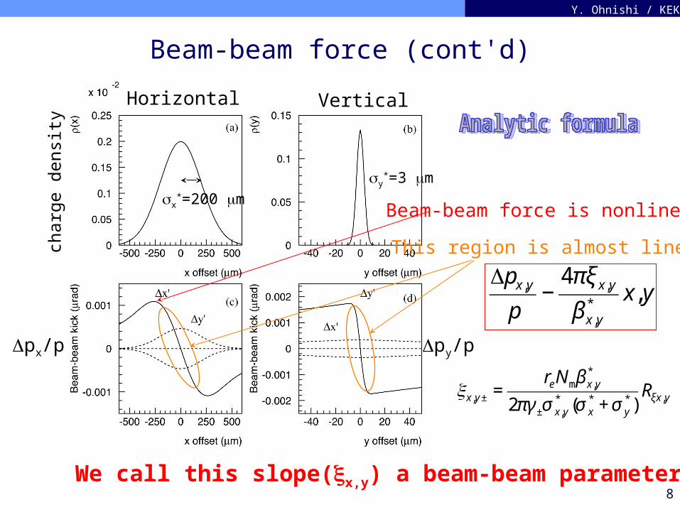
Beam-beam force (cont'd)
Δpx/p Δpy/p
Horizontal Vertical
This region is almost linear.
x*=200 m
y*=3 m
We call this slope(x,y) a beam-beam parameter.
€
Δpx,y
p−
4πξ x,y
β x,y*
x,y
€
x,y ± =reNmβ x,y
*
2πγ ±σ x,y* (σ x
* + σ y*)
Rξx,y
char
ge d
ensi
ty
Beam-beam force is nonlinear.
9
Y. Ohnishi / KEK
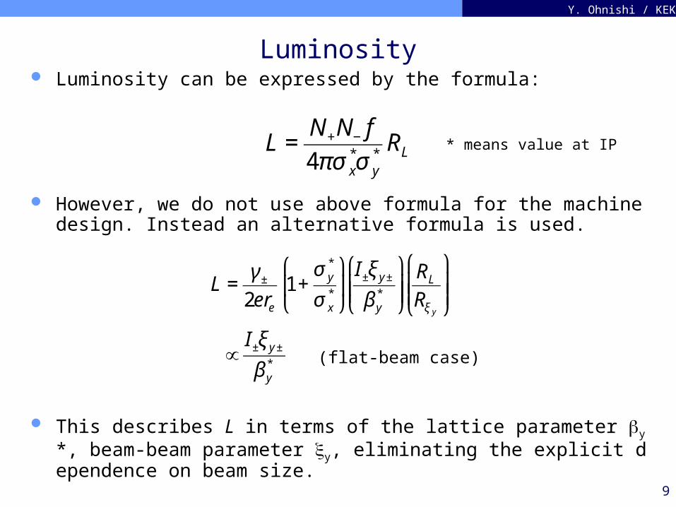
Luminosity Luminosity can be expressed by the formula:
However, we do not use above formula for the machine design. Instead an alternative formula is used.
This describes L in terms of the lattice parameter y*, beam-beam parameter y, eliminating the explicit dependence on beam size. €
L =γ ±
2ere
1+σ y
*
σ x*
⎛
⎝ ⎜
⎞
⎠ ⎟I±ξ y ±
β y*
⎛
⎝ ⎜ ⎜
⎞
⎠ ⎟ ⎟RL
Rξ y
⎛
⎝ ⎜ ⎜
⎞
⎠ ⎟ ⎟
∝I±ξ y ±
β y* (flat-beam case)
€
L =N+N− f
4πσ x*σ y
*RL * means value at IP
10
Y. Ohnishi / KEK
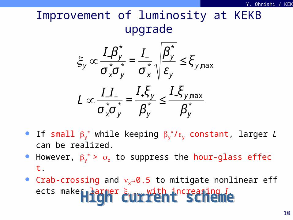
Improvement of luminosity at KEKB upgrade
If small y* while keeping y
*/y constant, larger L can be realized. However, y
* > z to suppress the hour-glass effect. Crab-crossing and x→0.5 to mitigate nonlinear effects makes larger
y,max with increasing I.€
y ∝I−β y
*
σ x*σ y
*=
I−
σ x*
β y*
εy
≤ ξ y,max
L∝I−I+
σ x*σ y
*=
I+ξ y
β y*
≤I+ξ y,max
β y*
11
Y. Ohnishi / KEK
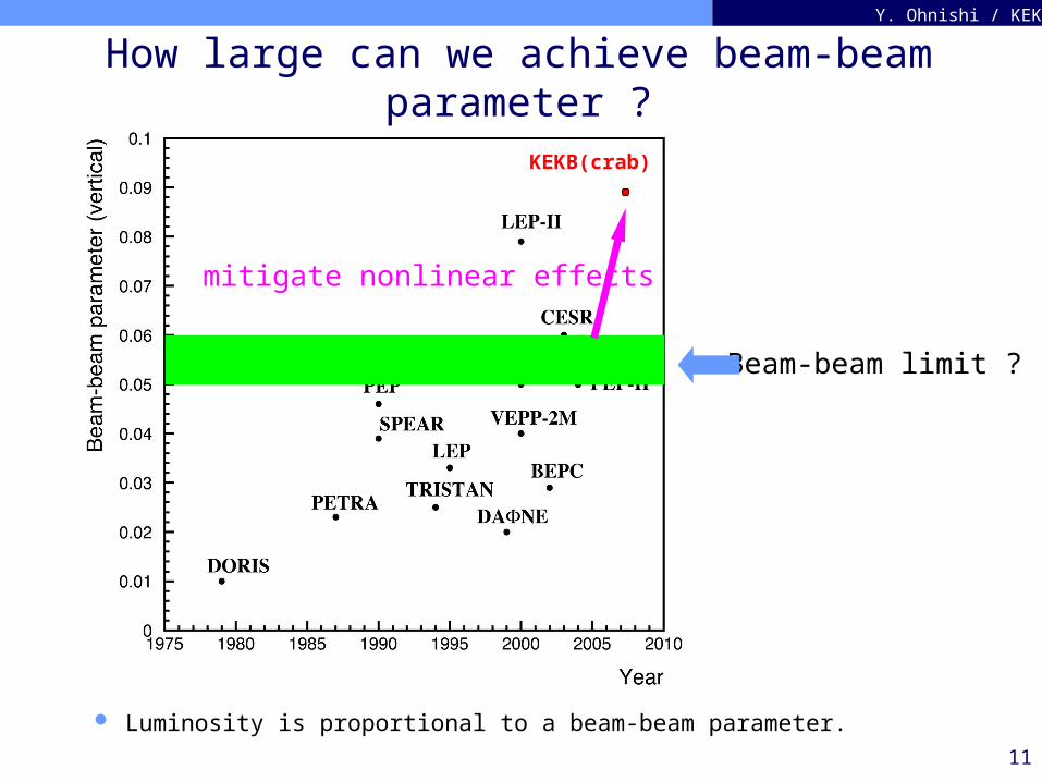
How large can we achieve beam-beam parameter ?
Luminosity is proportional to a beam-beam parameter.
Beam-beam limit ?
KEKB(crab)
mitigate nonlinear effects
12
Y. Ohnishi / KEK
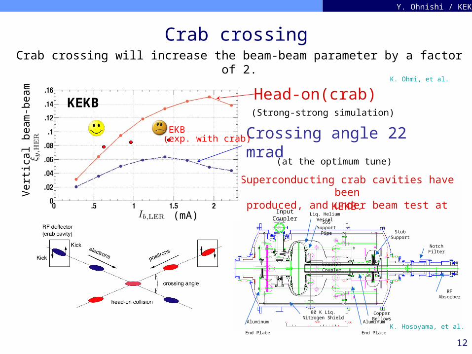
Crab crossing
Input Coupler
Liq. Helium Vessel
Stub Support
Coaxial Coupler
Copper Bellows
80 K Liq. Nitrogen Shield
Notch Filter
RF Absorber
Aluminum End
Plate
Aluminum End
Plate
SUS Support
Pipe
Crossing angle 22 mrad
Head-on(crab)(Strong-strong simulation)
Crab crossing will increase the beam-beam parameter by a factor of 2.
Superconducting crab cavities have beenproduced, and under beam test at KEKB.
(at the optimum tune)
Vert
ical beam
-beam
K. Hosoyama, et al.
K. Ohmi, et al.
(mA)
KEKB(exp. with crab)
KEKB
13
Y. Ohnishi / KEK
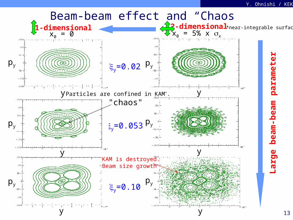
Beam-beam effect and “Chaos”
y=0.02
y=0.053
y=0.10
Lar
ge b
eam
-bea
m p
aram
eter
y
y
y
py
py
py
y
py
y
py
y
py
x0 = 0 x0 = 5% x x
1-dimensional 2-dimensional
"chaos"Particles are confined in KAM*.
KAM is destroyed.Beam size growth
*near-integrable surface
14
Y. Ohnishi / KEK
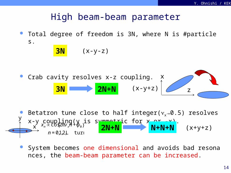
High beam-beam parameter
Total degree of freedom is 3N, where N is #particles.
Crab cavity resolves x-z coupling.
Betatron tune close to half integer(x→0.5) resolves x-y coupling(y is symmetric for x or -x).
System becomes one dimensional and avoids bad resonances, the beam-beam parameter can be increased.
3N 2N+N
N+N+N2N+N
3N (x-y-z)
(x-y+z)
(x+y+z)
z
x
€
xn ∝ cos 2πν xn +ψ 0( )
n = 0,1,2,L turns
y
x
15
Y. Ohnishi / KEK
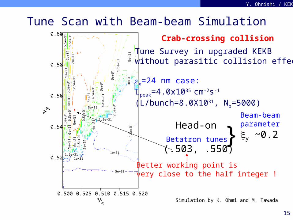
Tune Scan with Beam-beam Simulation
Tune Survey in upgraded KEKBwithout parasitic collision effect.
x=24 nm case:Lpeak=4.0x1035 cm-2s-1 (L/bunch=8.0X1031, Nb=5000)
0.60
0.58
0.56
0.54
0.52
0.5200.5150.5100.5050.500x
5e+31
1.5e+31
1.5e+31 1e+31
1e+31
5e+30
Simulation by K. Ohmi and M. Tawada
(.503, .550)
Head-on
} y ~0.2
Better working point isvery close to the half integer !
Betatron tunes
Beam-beamparameter
Crab-crossing collision
16
Y. Ohnishi / KEK
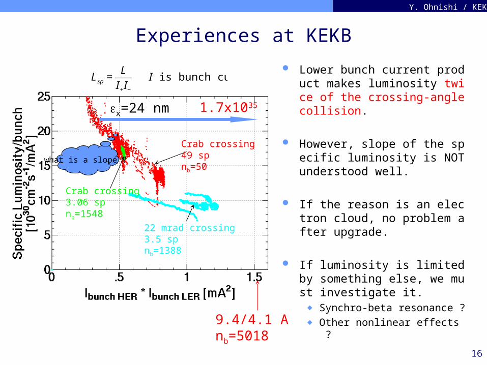
Experiences at KEKB
Lower bunch current product makes luminosity twice of the crossing-angle collision.
However, slope of the specific luminosity is NOT understood well.
If the reason is an electron cloud, no problem after upgrade.
If luminosity is limited by something else, we must investigate it.
◆ Synchro-beta resonance ?◆ Other nonlinear effects ?
Crab crossing3.06 spnb=1548
Crab crossing49 spnb=50
22 mrad crossing3.5 spnb=1388
1.7x1035
€
Lsp =L
I+I−
I is bunch current.
what is a slope ?
9.4/4.1 Anb=5018
x=24 nm
17
Y. Ohnishi / KEK
Luminosity upgrade
Assumptions: Specific luminosity/#bunches > 22x1030 cm-2s-1mA-2 with crab
cavities(factor of 2 at least) achieved at KEKB
High specific luminosity at high currents(9.4 A at LER) can be kept.
5000 bunches can be stored. No electron cloud and a bunch-by-bunch feedback system works
completely.
Believe a beam-beam simulation
18
Y. Ohnishi / KEK
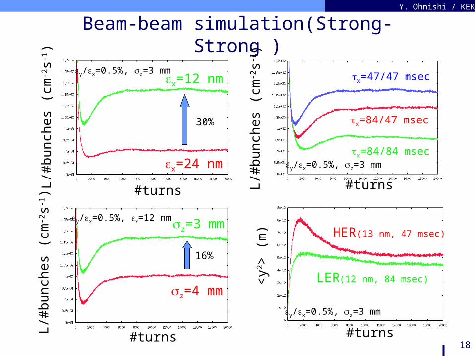
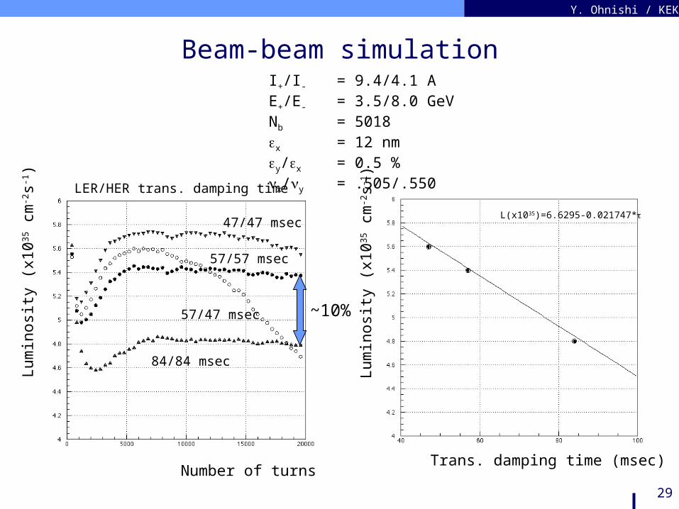
Beam-beam simulation(Strong-Strong )
L/#
bunc
hes
(cm
-2s-1
)
#turns
x=84/47 msec
x=84/84 msec
x=47/47 msec
y/x=0.5%, z=3 mm
#turns
L/#
bunc
hes
(cm
-2s-1
)
x=12 nm
x=24 nm
30%
y/x=0.5%, z=3 mm
#turns
L/#
bunc
hes
(cm
-2s-1
)
z=3 mm
z=4 mm
16%
y/x=0.5%, x=12 nm
HER(13 nm, 47 msec)
LER(12 nm, 84 msec)<y2 >
(m
)
#turns
y/x=0.5%, z=3 mm
19
Y. Ohnishi / KEK
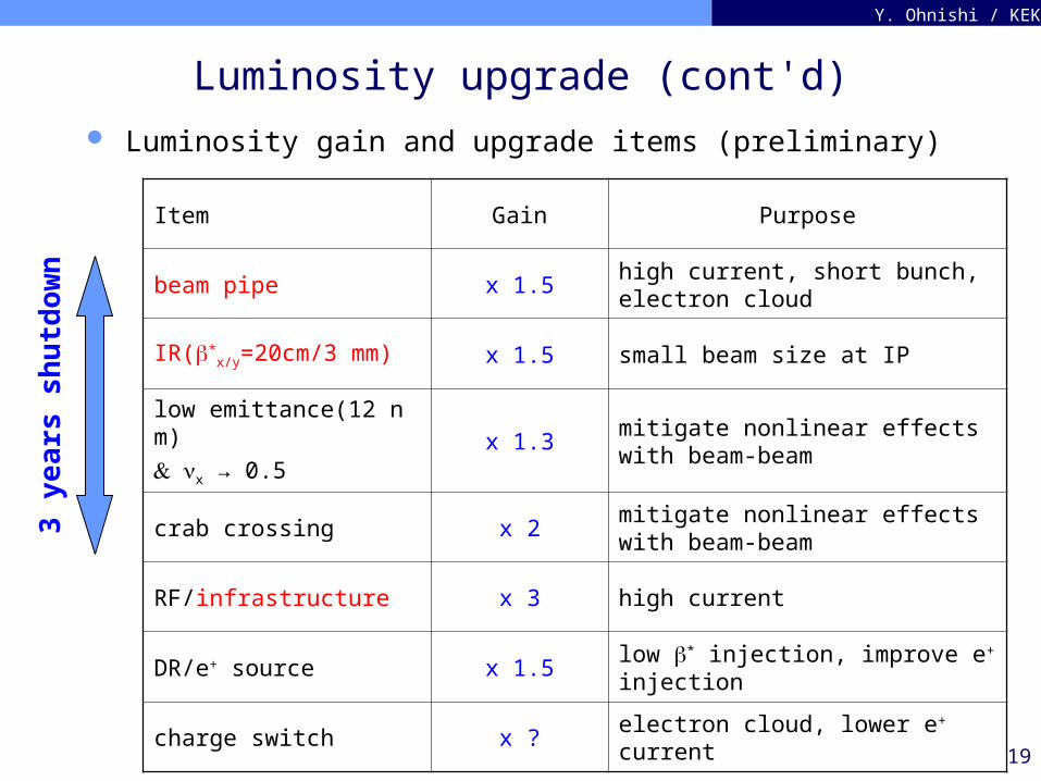
Luminosity upgrade (cont'd) Luminosity gain and upgrade items (preliminary)
Item Gain Purpose
beam pipe x 1.5high current, short bunch, electron cloud
IR(*x/y=20cm/3 mm) x 1.5 small beam size at IP
low emittance(12 nm) x → 0.5
x 1.3mitigate nonlinear effects with beam-beam
crab crossing x 2mitigate nonlinear effects with beam-beam
RF/infrastructure x 3 high current
DR/e+ source x 1.5low * injection, improve e+ injection
charge switch x ? electron cloud, lower e+ current
3 ye
ars
shu
tdow
n
20
Y. Ohnishi / KEK
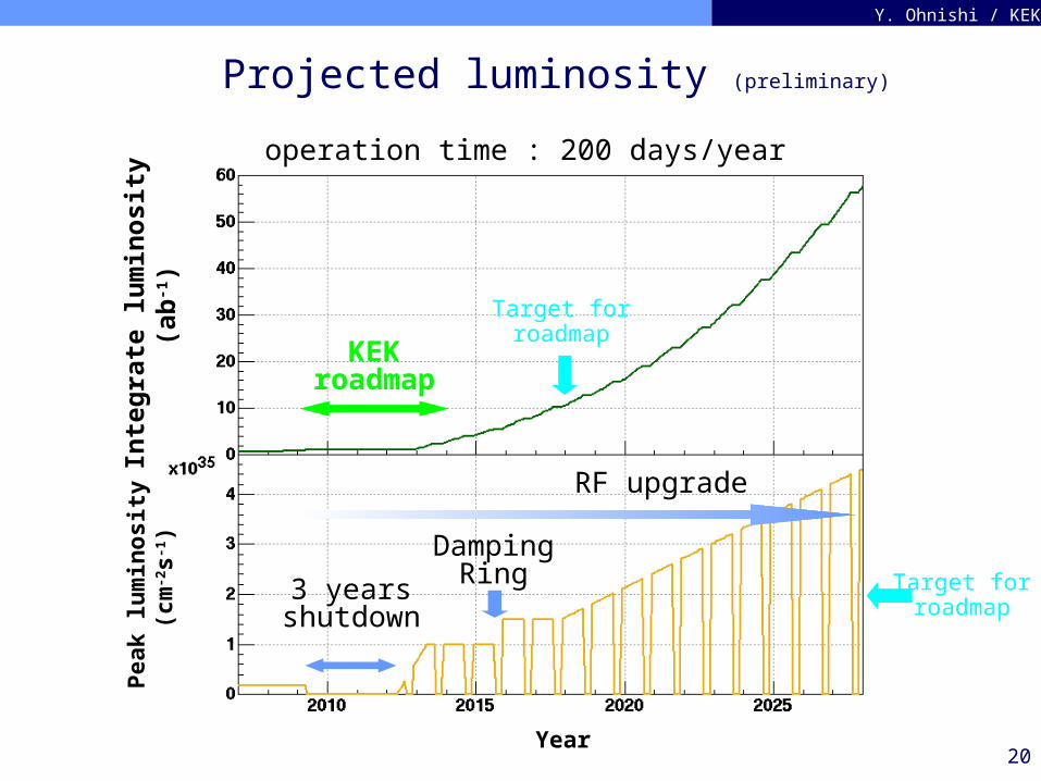
Projected luminosity (preliminary)
Inte
grat
e lu
min
osit
y (a
b-1)
Pea
k lu
min
osit
y (
cm-2s-1
)
Year
3 yearsshutdown
DampingRing
RF upgrade
KEKroadmap
operation time : 200 days/year
Target forroadmap
Target forroadmap
21
Y. Ohnishi / KEK
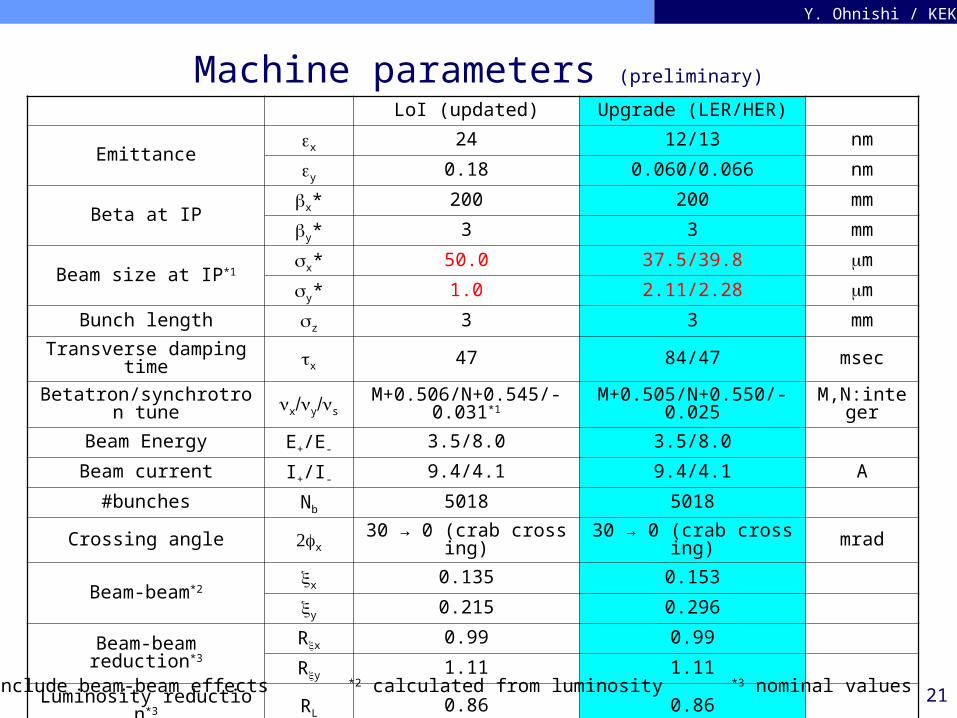
Machine parameters (preliminary)
LoI (updated) Upgrade (LER/HER)
Emittancex 24 12/13 nm
y 0.18 0.060/0.066 nm
Beta at IPx* 200 200 mm
y* 3 3 mm
Beam size at IP*1x* 50.0 37.5/39.8 m
y* 1.0 2.11/2.28 m
Bunch length z 3 3 mm
Transverse damping time x 47 84/47 msec
Betatron/synchrotron tune xysM+0.506/N+0.545/-0.0
31*1M+0.505/N+0.550/-0.0
25M,N:intege
r
Beam Energy E+/E- 3.5/8.0 3.5/8.0
Beam current I+/I- 9.4/4.1 9.4/4.1 A
#bunches Nb 5018 5018
Crossing angle x 30 → 0 (crab crossing) 30 → 0 (crab crossing) mrad
Beam-beam*2x 0.135 0.153
y 0.215 0.296
Beam-beamreduction*3
Rx 0.99 0.99
Ry 1.11 1.11
Luminosity reduction*3 RL 0.86 0.86
Luminosity L 4.0x1035 5.5x1035 cm-2s-1
*1 include beam-beam effects *2 calculated from luminosity *3 nominal values
22
Y. Ohnishi / KEK
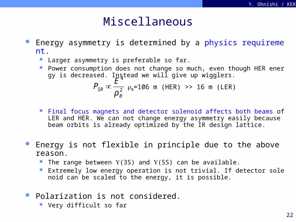
Miscellaneous
Energy asymmetry is determined by a physics requirement. Larger asymmetry is preferable so far. Power consumption does not change so much, even though HER energy is decrea
sed. Instead we will give up wigglers.
Final focus magnets and detector solenoid affects both beams of LER and HER. We can not change energy asymmetry easily because beam orbits is already optimized by the IR design lattice.
Energy is not flexible in principle due to the above reason. The range between (3S) and (5S) can be available. Extremely low energy operation is not trivial. If detector solenoid can be scaled to
the energy, it is possible.
Polarization is not considered. Very difficult so far
€
PSR ∝E 4
ρ B2 B=106 m (HER) >> 16 m (LER)
Y. Ohnishi / KEK
Backup slides
24
Y. Ohnishi / KEK
Sensitivity of physics
Higher asymmetry can achieve higer sensitivity for the physics results.Lower aymmetry(LER E=3.8 GeV), luminosity degradation is about 10~12 % luminosity.
Tajima
B→Ks
B→J/Ks
25
Y. Ohnishi / KEK
Synchrotron Radiation LossP r
ad (M
W)
total
LER
HER
LER wiggler
LER wiggler
LER E (GeV)
€
m4S2 = 4 ELER E HER
€
ELERILER = 3.5 × 9.4 GeV A
E HERIHER = 8.0 × 4.1 GeV A
€
Prad = U0I
€
L∝ E ⋅ I
*E=3.8 GeV in LER is maximum to perform Y(5S) experiment.
26
Y. Ohnishi / KEK
No. ARES cavities
LER E (GeV)
No.
AR
ES
cav
itie
s
No. SCC in HER = 8 (fixed)
LER
HER
LER+HER
No wiggler in LER / #SCC is 8.#RF cavities = ~40 → constant LoI: ARES/SCC=16/12
27
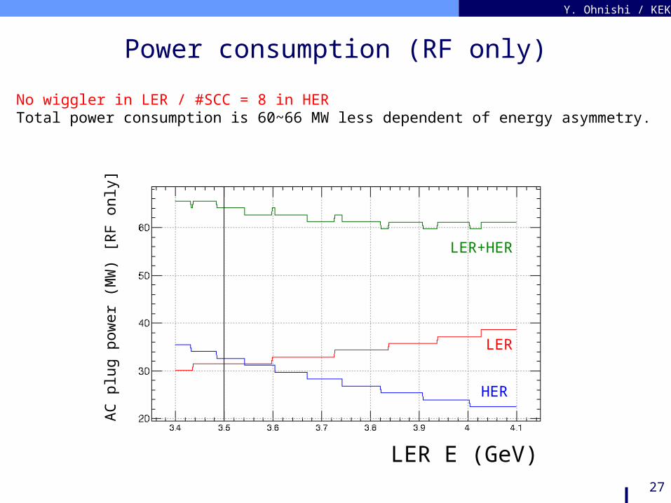
Y. Ohnishi / KEK
Power consumption (RF only)
AC
plu
g po
wer
(M
W)
[RF
onl
y]
LER E (GeV)
LER
HER
LER+HER
No wiggler in LER / #SCC = 8 in HERTotal power consumption is 60~66 MW less dependent of energy asymmetry.
28
Y. Ohnishi / KEK
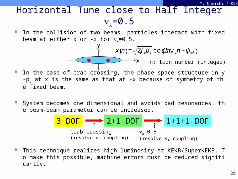
Horizontal Tune close to Half Integer x=0.5
In the collision of two beams, particles interact with fixed beam at either x or -x for x=0.5.
In the case of crab crossing, the phase space structure in y-py at x is the same as that at -x because of symmetry of the fixed beam.
System becomes one dimensional and avoids bad resonances, the beam-beam parameter can be increased.
This technique realizes high luminosity at KEKB/SuperKEKB. To make this possible, machine errors must be reduced significantly.
x
y
€
x n( ) = 2Jxβ x cos 2πν xn +ψ x0( )
3 DOF 2+1 DOF 1+1+1 DOFCrab-crossing(resolve xz coupling)
x=0.5(resolve xy coupling)
n: turn number (integer)
29
Y. Ohnishi / KEK
Beam-beam simulation
L(x1035)=6.6295-0.021747*
Trans. damping time (msec)
Lum
inos
ity
(x10
35 c
m-2s-1
)
Lum
inos
ity
(x10
35 c
m-2s-1
)
Number of turns
47/47 msec
57/57 msec
84/84 msec
57/47 msec
LER/HER trans. damping time
I+/I- = 9.4/4.1 AE+/E- = 3.5/8.0 GeVNb = 5018x = 12 nmy/x = 0.5 %x/y = .505/.550
~10%