
updated DVPDT02 eng cvr 20090723 - deltaww.com€¦ · 6 LED INDICATORS & TROUBLE-SHOOTING ......
28
DVPDT02-H2 DeviceNet Slave Communication Module Operation Manual DVP-0205120-02
Transcript of updated DVPDT02 eng cvr 20090723 - deltaww.com€¦ · 6 LED INDICATORS & TROUBLE-SHOOTING ......
DVPDT02-H2 DeviceNet Slave Communication Module Operation Manual
DVP-0205120-02

DeviceNet Slave Communication Module DVPDT02-H2
DVP-PLC Operation Manual 1
Warning Please read this instruction carefully before use and follow this instruction to operate the device in order to prevent
damages on the device or injuries to staff.
Switch off the power before wiring.
DVPDT02-H2 is an OPEN TYPE device and therefore should be installed in an enclosure free of airborne dust,
humidity, electric shock and vibration. The enclosure should prevent non-maintenance staff from operating the
device (e.g. key or specific tools are required for operating the enclosure) in case danger and damage on the
device may occur.
DVPDT02-H2 is to be used for controlling the operating machine and equipment. In order not to damage it, only
qualified professional staff familiar with the structure and operation of DVPDT02-H2 can install, operate, wire
and maintain it.
DO NOT connect input AC power supply to any of the I/O terminals; otherwise serious damage may occur. Check
all the wirings again before switching on the power and DO NOT touch any terminal when the power is switched
on. Make sure the ground terminal is correctly grounded in order to prevent electromagnetic interference.
Table of Contents
1 INTRODUCTION.................................................................................................................................3 1.1 Features ..................................................................................................................................3 1.2 Specifications ..........................................................................................................................3
2 PRODUCT PROFILE & OUTLINE .....................................................................................................4 2.1 Dimension ...............................................................................................................................4 2.2 Product Profiles .......................................................................................................................4 2.3 DeviceNet Connection Port .....................................................................................................5 2.4 Address Switch........................................................................................................................5 2.5 Function Switch .......................................................................................................................5 2.6 I/O Module Connection Port ....................................................................................................6
3 BASIC OPERATION...........................................................................................................................6 3.1 Connecting DVPDT02-H2 to DVP-EH2 Series PLC MPU ......................................................6 3.2 Install DVP-EH2 and DVPDT02-H2 on DIN Rail .....................................................................6 3.3 Connecting to DeviceNet Connection Port..............................................................................7
4 CONFIGURATING DVPDT02-H2 .......................................................................................................7 4.1 Format of Request Message and Response Message ...........................................................7 4.2 Control Registers (CR) in DVPDT02-H2 .................................................................................8 4.3 Error Codes .............................................................................................................................9
5 HOW TO CONSTRUCT DEVICENET NETWORK BY DVPDT02-H2................................................9 5.1 Application Example I..............................................................................................................9
DeviceNet Slave Communication Module DVPDT02-H2
DVP-PLC Operation Manual 2
5.2 Application Example II .......................................................................................................... 17 6 LED INDICATORS & TROUBLE-SHOOTING................................................................................. 20
6.1 POWER LED ........................................................................................................................ 20 6.2 NS LED................................................................................................................................. 20 6.3 MS LED ................................................................................................................................ 20 6.4 NS LED + MS LED ............................................................................................................... 21
APPENDIX A: DEVICENET OBJECTS DVPDT02-H2 SUPPORTS ....................................................... 21 APPENDIX B: DEVICENET OJECTS DEFINED BY DVPDT02-H2........................................................ 24

DeviceNet Slave Communication Module DVPDT02-H2
DVP-PLC Operation Manual 3
1 Introduction
1. To ensure correct installation and proper operation of DVPDT02-H2, please read this chapter carefully
before using your DVPDT02-H2.
2. This chapter only provides introductory information on DVPDT02-H2. Details of DeviceNet protocol are not
included. For more information on DeviceNet protocol, please refer to relevant reference or literatures.
3. DVPDT02-H2 is a DeviceNet slave communication module, used for the connection between DeviceNet
network and DVP-EH2 series PLC MPU.
1.1 Features
Supports Group 2 only servers.
Supports explicit connection in the pre-defined master/slave connection group.
Supports polling.
Supports EDS files in DeviceNet network configuration tools.
The length of I/O data can be freely configured through DeviceNet network configuration tool. Re-power
it to make effect the configuration.
I/O data is extendable to 200 bytes.
1.2 Specifications
DeviceNet connection
Transmission method CAN
Electrical isolation 500VDC
Interface Removable connector (5.08mm)
Transmission cable 2 communication cables, 2 power cables, 1 shielded cable
Communication
Message type I/O polling; explicit
Serial transmission speed 125 kbps; 250 kbps; 500 kbps (bits per second)
Electrical specification
Voltage 24VDC (Range: 11 ~ 25VDC)
Current 28mA (typical), 125mA impulse current (24VDC)
Environment
Noise immunity
ESD (IEC 61131-2, IEC 61000-4-2): 8KV Air Discharge EFT (IEC 61131-2, IEC 61000-4-4): Power Line: 2KV, Digital I/O: 1KV Analog & Communication I/O: 1KV Damped-Oscillatory Wave: Power Line: 1KV, Digital I/O: 1KV RS (IEC 61131-2, IEC 61000-4-3): 26MHz ~ 1GHz, 10V/m
Operation 0ºC ~ 55ºC (temperature); 50 ~ 95% (humidity); pollution degree 2
Storage -25ºC ~ 70ºC (temperature); 5 ~ 95% (humidity)
Vibration/shock resistance
Standard: IEC 61131-2, IEC 68-2-6 (TEST Fc)/IEC 61131-2 & IEC 68-2-27 (TEST Ea)
Certificates IEC 61131-2, UL508
DeviceNet Slave Communication Module DVPDT02-H2
DVP-PLC Operation Manual 4
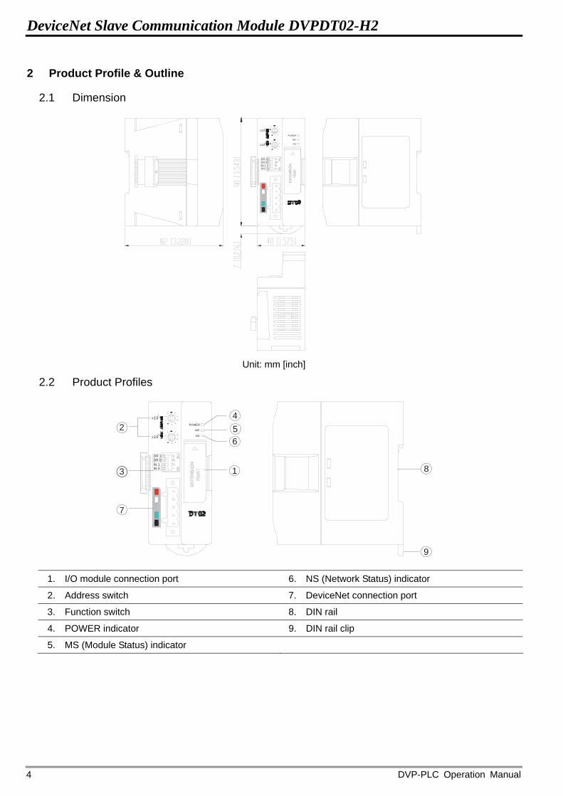
2 Product Profile & Outline
2.1 Dimension
POWER
NS
MS
DR 1DR 0
IN 0IN 1
X10
X10
Unit: mm [inch]
2.2 Product Profiles
POWER
NS
MS
DR 1DR 0
IN 0IN 1
X10
X10
2
3
54
6
7
8
9
1
1. I/O module connection port 6. NS (Network Status) indicator
2. Address switch 7. DeviceNet connection port
3. Function switch 8. DIN rail
4. POWER indicator 9. DIN rail clip
5. MS (Module Status) indicator

DeviceNet Slave Communication Module DVPDT02-H2
DVP-PLC Operation Manual 5
2.3 DeviceNet Connection Port
The connector is used on the connection to DeviceNet network. Wire by using the connector enclosed with
DVPDT02-H2.
PIN Signal Color Contect
1 V- Black 0 VDC
2 CAN_L Blue Signal-
3 SHIELD - Shielded
4 CAN_H White Signal+
5 V+ Red 24 VDC
12345
2.4 Address Switch
The switch is used on setting up the node address of DVPDT02-H2 on DeviceNet network.
Switch setting Content
0 ~ 63 Valid DeviceNet node address
64~ 99 Invalid DeviceNet node address X10
X10
Example: If you need to set the node address of DVPDT02-H2 to 26, simply switch the corresponding switch
of x101 to 2 and the corresponding switch of x100 to 6.
Note: Please set up the node address when the power is switched off. After the setup is completed, re-power
DVPDT02-H2. When DVPDT02-H2 is operating, changing the set value of the node address will be invalid. Use slotted screwdriver to rotate the switch carefully in case you scratch the switch.
2.5 Function Switch
The switches are for:
Setting up I/O data holding function (IN0).
Setting up baud rates of DeviceNet network (DR0 ~ DR1).
DR1 DR0 Baud rate
OFF OFF 125 kbps
OFF ON 250 kbps
ON OFF 500 kbps
ON ON Incorrect setting
OFF When the DeviceNet connection is interrupted, the content in the buffer area will not be held.
IN0
ON When the DeviceNet connection is interrupted, the content in the buffer area will be held.
IN1 Reserved
DR 1DR 0
IN 0IN 1
Note:
DeviceNet Slave Communication Module DVPDT02-H2
DVP-PLC Operation Manual 6
Please set up the switch when the power is switched off. After the setup is completed, re-power
DVPDT02-H2. When DVPDT02-H2 is operating, changing the setting of the switch will be invalid. Use slotted screwdriver to adjust the switch carefully in case you scratch the switch.
2.6 I/O Module Connection Port
The I/O module connection port on DVPDT02-H2 is used for the connection to the next DVPDT02-H2 or I/O
modules of DVP-EH2 series PLC MPU.
3 Basic Operation
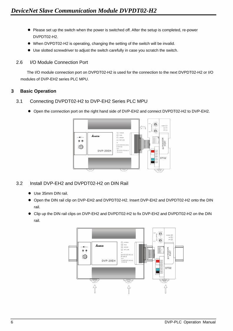
3.1 Connecting DVPDT02-H2 to DVP-EH2 Series PLC MPU
Open the connection port on the right hand side of DVP-EH2 and connect DVPDT02-H2 to DVP-EH2.
ST OP R UN
0 1
IN
OU T
PO W ER
R U N
ER R OR
BAT. LOW
DVP-20EH
3.2 Install DVP-EH2 and DVPDT02-H2 on DIN Rail
Use 35mm DIN rail.
Open the DIN rail clip on DVP-EH2 and DVPDT02-H2. Insert DVP-EH2 and DVPDT02-H2 onto the DIN
rail.
Clip up the DIN rail clips on DVP-EH2 and DVPDT02-H2 to fix DVP-EH2 and DVPDT02-H2 on the DIN
rail.
STOP R UN
0 1
IN
OU T
PO W ER
RU N
ER R OR
BAT. LOW
DVP-20EH

DeviceNet Slave Communication Module DVPDT02-H2
DVP-PLC Operation Manual 7
3.3 Connecting to DeviceNet Connection Port
The colors of the PINs on the DeviceNet connection port match the colors of the connection cables. Make
sure you connect the cable to the right PIN.
We recommend you also apply Delta’s power module in the connection.
4 Configurating DVPDT02-H2
4.1 Format of Request Message and Response Message
1. DVPDT02-H2 supports polling by standard DeviceNet explicit messages.
Format of request messages:
Byte position Data written into special I/O module Data read from special I/O module
0 Frag[0]+XID+MAC ID Frag[0]+XID+MAC ID
1 R/R[0]+Service Code [0x10] R/R[0]+Service Code [0x0E]
2 Class ID [0x95] Class ID [0x95]
3 Instance ID Instance ID
4 Attribute ID Attribute ID
5 Low byte of Service Data N/A
6 High byte of Service Data N/A
7 N/A N/A
Format of response messages
Byte position Data written into special I/O module Data read from special I/O module
0 Frag[0]+XID+MAC ID Frag[0]+XID+MAC ID
1 R/R[1]+Service Code [0x10] R/R[1]+Service Code [0x0E]
2 Low byte of response data
3 High byte of response data
2. Definitions of DeviceNet Objects for DVPDT02-H2:
Class 0x95 – DVPDT02-H2 I/O data configuration object
Class attribute
Attribute ID Access rule Name Data type
1 Get Revision UINT
DeviceNet Slave Communication Module DVPDT02-H2
DVP-PLC Operation Manual 8
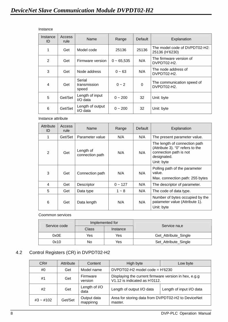
Instance
Instance ID
Access rule Name Range Default Explanation
1 Get Model code 25136 25136 The model code of DVPDT02-H2: 25136 (H’6230)
2 Get Firmware version 0 ~ 65,535 N/A The firmware version of DVPDT02-H2.
3 Get Node address 0 ~ 63 N/A The node address of DVPDT02-H2.
4 Get Serial transmission speed
0 ~ 2 0 The communication speed of DVPDT02-H2.
5 Get/Set Length of input I/O data 0 ~ 200 32 Unit: byte
6 Get/Set Length of output I/O data 0 ~ 200 32 Unit: byte
Instance attribute
Attribute ID
Access rule Name Range Default Explanation
1 Get/Set Parameter value N/A N/A The present parameter value.
2 Get Length of connection path N/A N/A
The length of connection path (Attribute 3). “0” refers to the connection path is not designated. Unit: byte
3 Get Connection path N/A N/A Polling path of the parameter value. Max. connection path: 255 bytes
4 Get Descriptor 0 ~ 127 N/A The descriptor of parameter.
5 Get Data type 1 ~ 8 N/A The code of data type.
6 Get Data length N/A N/A Number of bytes occupied by the patameter value (Attribute 1). Unit: byte
Coommon services
Implemented for Service code
Class Instance Service na,e
0x0E Yes Yes Get_Attribute_Single
0x10 No Yes Set_Attribute_Single
4.2 Control Registers (CR) in DVPDT02-H2
CR# Attribute Content High byte Low byte
#0 Get Model name DVPDT02-H2 model code = H’6230
#1 Get Firmware version
Displaying the current firmware version in hex, e.g.g V1.12 is indicated as H’0112.
#2 Get Length of I/O data Length of output I/O data Length of input I/O data
#3 ~ #102 Get/Set Output data mappinng
Area for storing data from DVPDT02-H2 to DeviceNet master.
DeviceNet Slave Communication Module DVPDT02-H2
DVP-PLC Operation Manual 9
CR# Attribute Content High byte Low byte
#103 ~ #202 Get/Set Input data mappinig
Area for storing data from DeviceNet master to DVPDT02-H2.
#203 ~ #215 Set up by the system. DO NOT use it.
#216 ~ #250 Reserved
#251 Get Error Register for storing errors. See 19.4.3 for error codes.
#252 ~ #254 Reserved
#255 Get MPU status CR#255 = K0: MPU in STOP status CR#255 = K1: MPU in RUN status
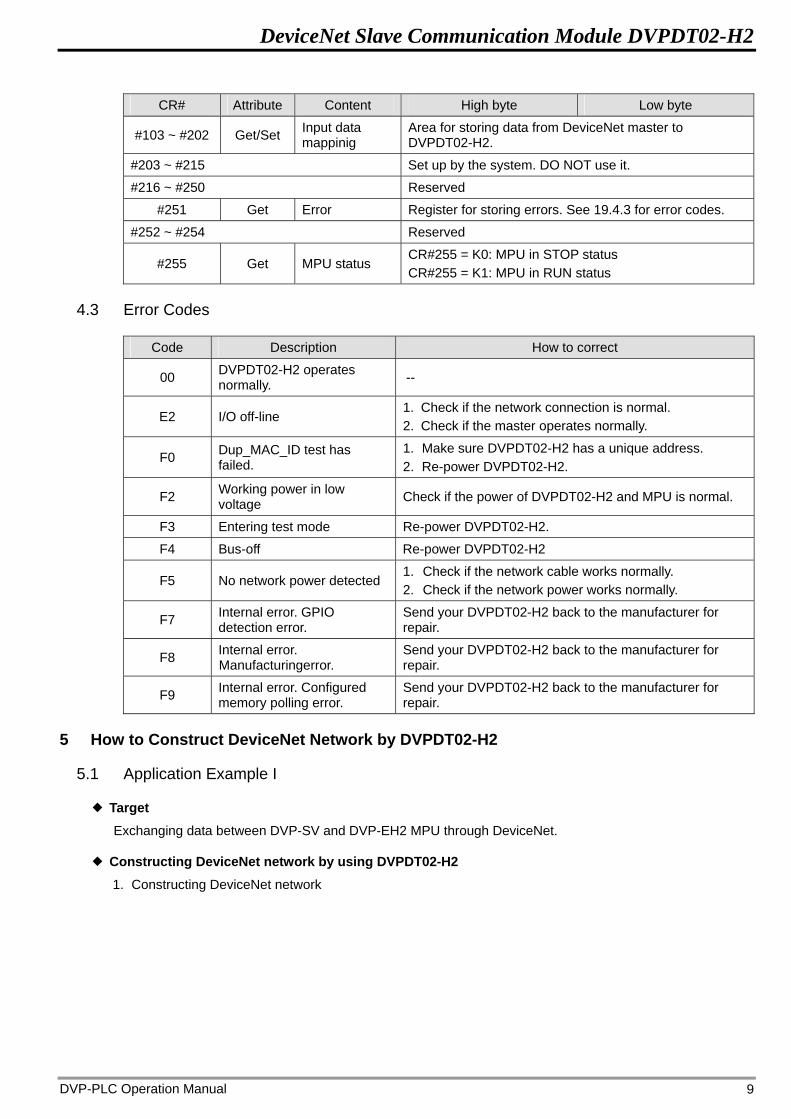
4.3 Error Codes
Code Description How to correct
00 DVPDT02-H2 operates normally. --
E2 I/O off-line 1. Check if the network connection is normal. 2. Check if the master operates normally.
F0 Dup_MAC_ID test has failed.
1. Make sure DVPDT02-H2 has a unique address. 2. Re-power DVPDT02-H2.
F2 Working power in low voltage Check if the power of DVPDT02-H2 and MPU is normal.
F3 Entering test mode Re-power DVPDT02-H2.
F4 Bus-off Re-power DVPDT02-H2
F5 No network power detected 1. Check if the network cable works normally. 2. Check if the network power works normally.
F7 Internal error. GPIO detection error.
Send your DVPDT02-H2 back to the manufacturer for repair.
F8 Internal error. Manufacturingerror.
Send your DVPDT02-H2 back to the manufacturer for repair.
F9 Internal error. Configured memory polling error.
Send your DVPDT02-H2 back to the manufacturer for repair.
5 How to Construct DeviceNet Network by DVPDT02-H2
5.1 Application Example I
Target Exchanging data between DVP-SV and DVP-EH2 MPU through DeviceNet.
Constructing DeviceNet network by using DVPDT02-H2 1. Constructing DeviceNet network

DeviceNet Slave Communication Module DVPDT02-H2
DVP-PLC Operation Manual 10
DeviceNet
DVP28SVDVPDNET-SL
DVPDNET DVP28SV
RUN
STOP
Master
DeviceNetnetwork configuration tool
STOP RUN
0 1
IN
OUT
POWER
RUN
ERROR
BAT.LOW
DVP-20EH
2. Configuring DVPDNET-SL network scanner and DVPDT02-H2:
Module Node address Baud rate
DVPDNET-SL 1 500kbps
DVPDT02-H2 2 500kbps
3. Please check and make sure DVP-EH2 PLC MPU and DVPDT02-H2 module both operate normally.
Check also the wiring of the entire network and make sure the power supply on DeviceNet network is
normal.
Configuring the network by DeviceNet network configuration tool Configuration DVPDT02-H2
1. Open DeviceNetBuilder.
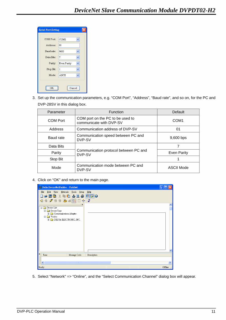
2. Select “Setup“ => “Communication Setting” => “System Channel”, and you will see the “Serial Port Setting”
dialog box.
DeviceNet Slave Communication Module DVPDT02-H2
DVP-PLC Operation Manual 11
3. Set up the communication parameters, e.g. “COM Port”, “Address”, “Baud rate”, and so on, for the PC and
DVP-28SV in this dialog box.
Parameter Function Default
COM Port COM port on the PC to be used to communicate with DVP-SV COM1
Address Communication address of DVP-SV 01
Baud rate Communication speed between PC and DVP-SV 9,600 bps
Data Bits 7
Parity Even Parity
Stop Bit
Communication protocol between PC and DVP-SV
1
Mode Communication mode between PC and DVP-SV ASCII Mode
4. Click on “OK” and return to the main page.
5. Select “Network" => “Online”, and the “Select Communication Channel” dialog box will appear.

DeviceNet Slave Communication Module DVPDT02-H2
DVP-PLC Operation Manual 12
6. Click on “OK”, and DeviceNetBuilder will start to scan the entire network.
7. If the bar on the dialog box does not progress, it means the connection between the PC and DVP-SV is
abnormal, or there are other programs also using the COM port on the PC. After the scan is completed, the
dialog box will tell you that the scan is completed, and the icons and device names of all the nodes
scanned on the network will be shown on the screen. See the figure below, in which the node address of
DVPDNET-SL is 01.
8. Double click on DVPDT02-H2 (node 02), and the “Node Configuration...” dialog box will appear.
DeviceNet Slave Communication Module DVPDT02-H2
DVP-PLC Operation Manual 13
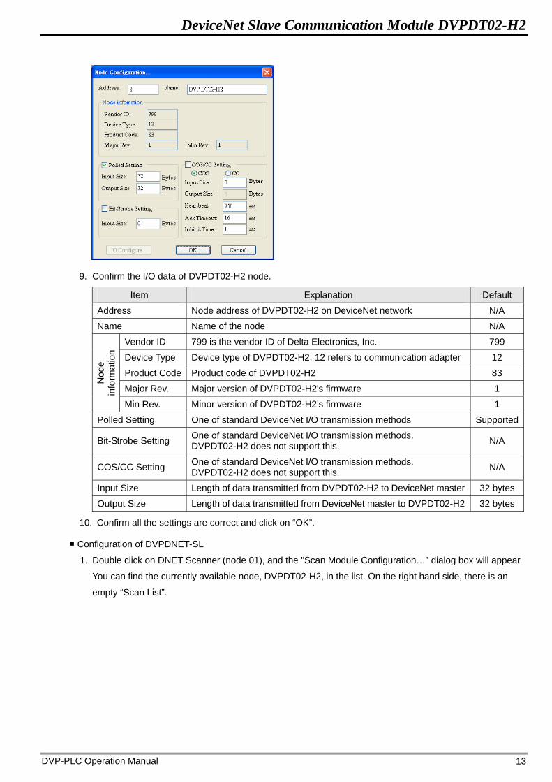
9. Confirm the I/O data of DVPDT02-H2 node.
Item Explanation Default
Address Node address of DVPDT02-H2 on DeviceNet network N/A
Name Name of the node N/A
Vendor ID 799 is the vendor ID of Delta Electronics, Inc. 799
Device Type Device type of DVPDT02-H2. 12 refers to communication adapter 12
Product Code Product code of DVPDT02-H2 83
Major Rev. Major version of DVPDT02-H2's firmware 1
Nod
e in
form
atio
n
Min Rev. Minor version of DVPDT02-H2’s firmware 1
Polled Setting One of standard DeviceNet I/O transmission methods Supported
Bit-Strobe Setting One of standard DeviceNet I/O transmission methods. DVPDT02-H2 does not support this. N/A
COS/CC Setting One of standard DeviceNet I/O transmission methods. DVPDT02-H2 does not support this. N/A
Input Size Length of data transmitted from DVPDT02-H2 to DeviceNet master 32 bytes
Output Size Length of data transmitted from DeviceNet master to DVPDT02-H2 32 bytes
10. Confirm all the settings are correct and click on “OK”.
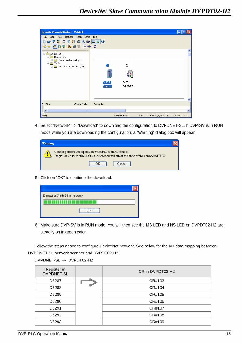
Configuration of DVPDNET-SL
1. Double click on DNET Scanner (node 01), and the "Scan Module Configuration…” dialog box will appear.
You can find the currently available node, DVPDT02-H2, in the list. On the right hand side, there is an
empty “Scan List”.

DeviceNet Slave Communication Module DVPDT02-H2
DVP-PLC Operation Manual 14
2. Move the slave devices on DeviceNet in the “Available Nodes” list on the left hand side to the “Scan List”
on the right hand side. Select a node and click on > . Follow the steps to move all the nodes to the scan
list.
3. Confirm all the settings and click on “OK” to return to the main page.
DeviceNet Slave Communication Module DVPDT02-H2
DVP-PLC Operation Manual 15
4. Select “Network” => “Download” to download the configuration to DVPDNET-SL. If DVP-SV is in RUN
mode while you are downloading the configuration, a “Warning” dialog box will appear.
5. Click on “OK” to continue the download.
6. Make sure DVP-SV is in RUN mode. You will then see the MS LED and NS LED on DVPDT02-H2 are
steadily on in green color.
Follow the steps above to configure DeviceNet network. See below for the I/O data mapping between
DVPDNET-SL network scanner and DVPDT02-H2.
DVPDNET-SL → DVPDT02-H2
Register in DVPDNET-SL CR in DVPDT02-H2
D6287 CR#103
D6288 CR#104
D6289 CR#105
D6290 CR#106
D6291 CR#107
D6292 CR#108
D6293
CR#109
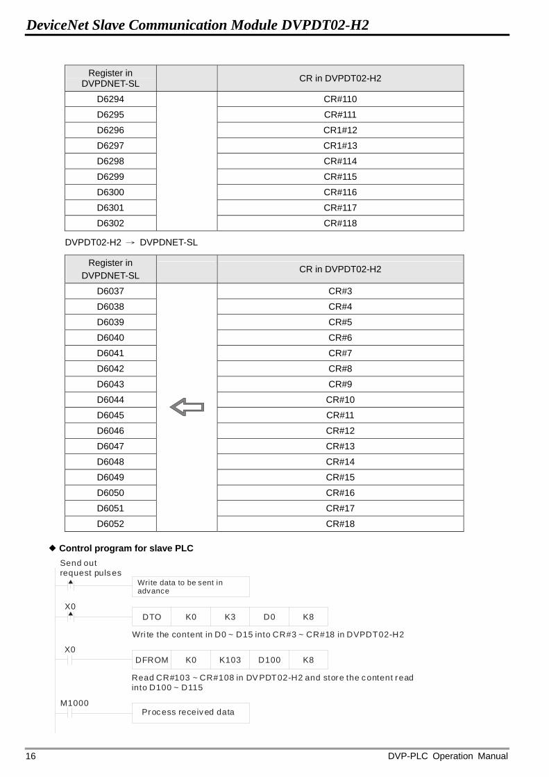
DeviceNet Slave Communication Module DVPDT02-H2
DVP-PLC Operation Manual 16
Register in DVPDNET-SL CR in DVPDT02-H2
D6294 CR#110
D6295 CR#111
D6296 CR1#12
D6297 CR1#13
D6298 CR#114
D6299 CR#115
D6300 CR#116
D6301 CR#117
D6302 CR#118
DVPDT02-H2 → DVPDNET-SL
Register in DVPDNET-SL
CR in DVPDT02-H2
D6037 CR#3
D6038 CR#4
D6039 CR#5
D6040 CR#6
D6041 CR#7
D6042 CR#8
D6043 CR#9
D6044 CR#10
D6045 CR#11
D6046 CR#12
D6047 CR#13
D6048 CR#14
D6049 CR#15
D6050 CR#16
D6051 CR#17
D6052
CR#18
Control program for slave PLC
DTO
DFROM
K0
K0
K3
K103
D0
D100
K8
K8
X0
X0
M1000
Send out request pulses
Write data to be sent inadvance
Wri te the content in D0 ~ D15 into CR#3 ~ CR#18 in DVPDT02-H2
Read CR#103 ~ CR#108 in DV PDT02-H2 and store the content readinto D100 ~ D115
Process received data
DeviceNet Slave Communication Module DVPDT02-H2
DVP-PLC Operation Manual 17
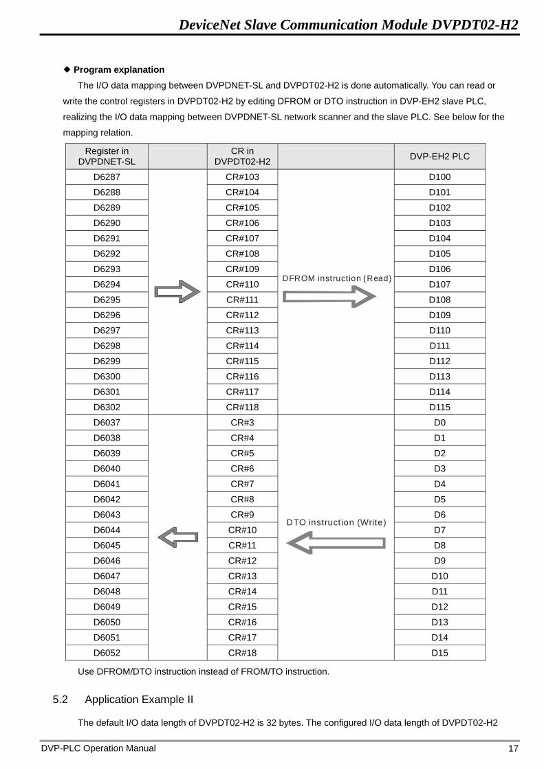
Program explanation The I/O data mapping between DVPDNET-SL and DVPDT02-H2 is done automatically. You can read or
write the control registers in DVPDT02-H2 by editing DFROM or DTO instruction in DVP-EH2 slave PLC,
realizing the I/O data mapping between DVPDNET-SL network scanner and the slave PLC. See below for the
mapping relation.
Register in DVPDNET-SL CR in
DVPDT02-H2 DVP-EH2 PLC
D6287 CR#103 D100
D6288 CR#104 D101
D6289 CR#105 D102
D6290 CR#106 D103
D6291 CR#107 D104
D6292 CR#108 D105
D6293 CR#109 D106
D6294 CR#110 D107
D6295 CR#111 D108
D6296 CR#112 D109
D6297 CR#113 D110
D6298 CR#114 D111
D6299 CR#115 D112
D6300 CR#116 D113
D6301 CR#117 D114
D6302
CR#118
DFROM instruction (Read)
D115
D6037 CR#3 D0
D6038 CR#4 D1
D6039 CR#5 D2
D6040 CR#6 D3
D6041 CR#7 D4
D6042 CR#8 D5
D6043 CR#9 D6
D6044 CR#10 D7
D6045 CR#11 D8
D6046 CR#12 D9
D6047 CR#13 D10
D6048 CR#14 D11
D6049 CR#15 D12
D6050 CR#16 D13
D6051 CR#17 D14
D6052
CR#18
DTO instruction (Write)
D15
Use DFROM/DTO instruction instead of FROM/TO instruction.
5.2 Application Example II
The default I/O data length of DVPDT02-H2 is 32 bytes. The configured I/O data length of DVPDT02-H2
DeviceNet Slave Communication Module DVPDT02-H2
DVP-PLC Operation Manual 18
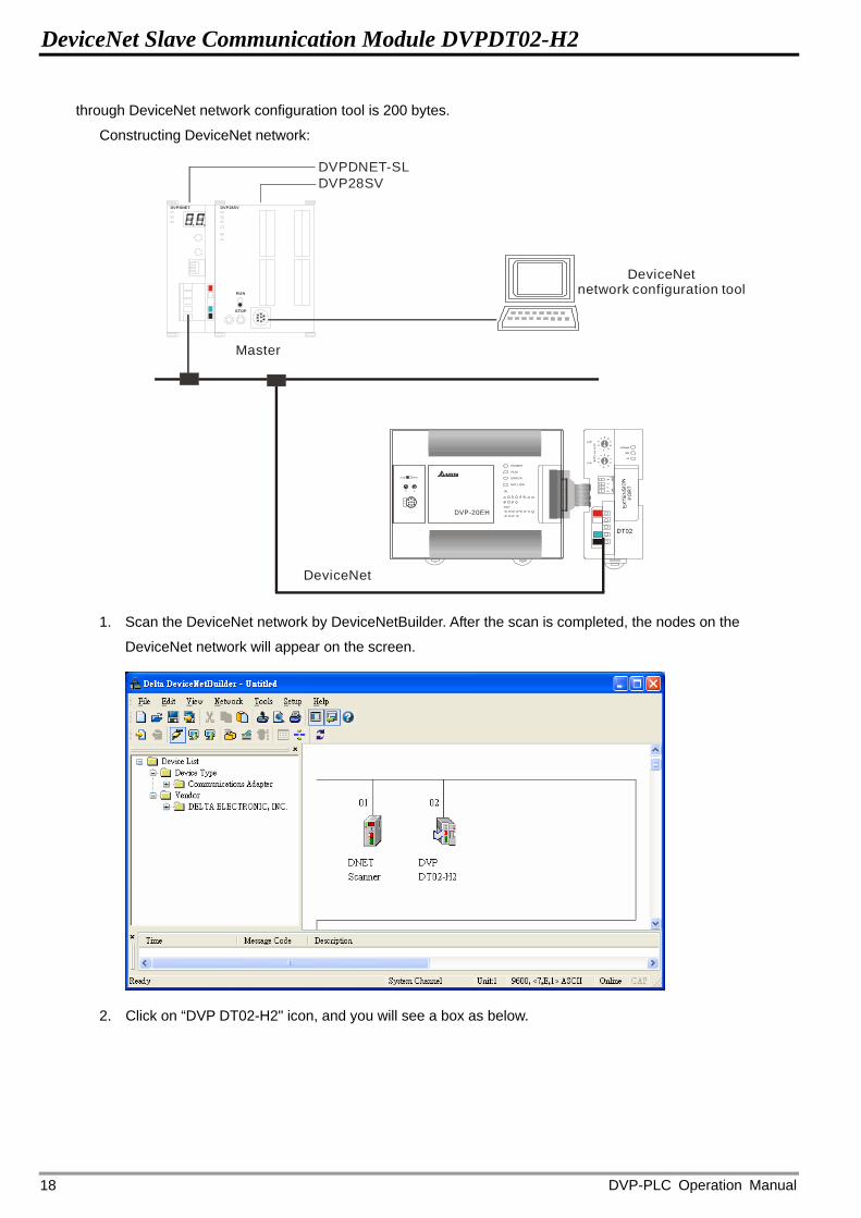
through DeviceNet network configuration tool is 200 bytes.
Constructing DeviceNet network:
DeviceNet
DVP28SVDVPDNET-SL
DVPDNET DVP28SV
RUN
STOP
Master
DeviceNetnetwork configuration tool
STOP RUN
0 1
IN
OUT
POWER
RUN
ERROR
BAT.LOW
DVP-20EH
1. Scan the DeviceNet network by DeviceNetBuilder. After the scan is completed, the nodes on the
DeviceNet network will appear on the screen.
2. Click on “DVP DT02-H2" icon, and you will see a box as below.
DeviceNet Slave Communication Module DVPDT02-H2
DVP-PLC Operation Manual 19
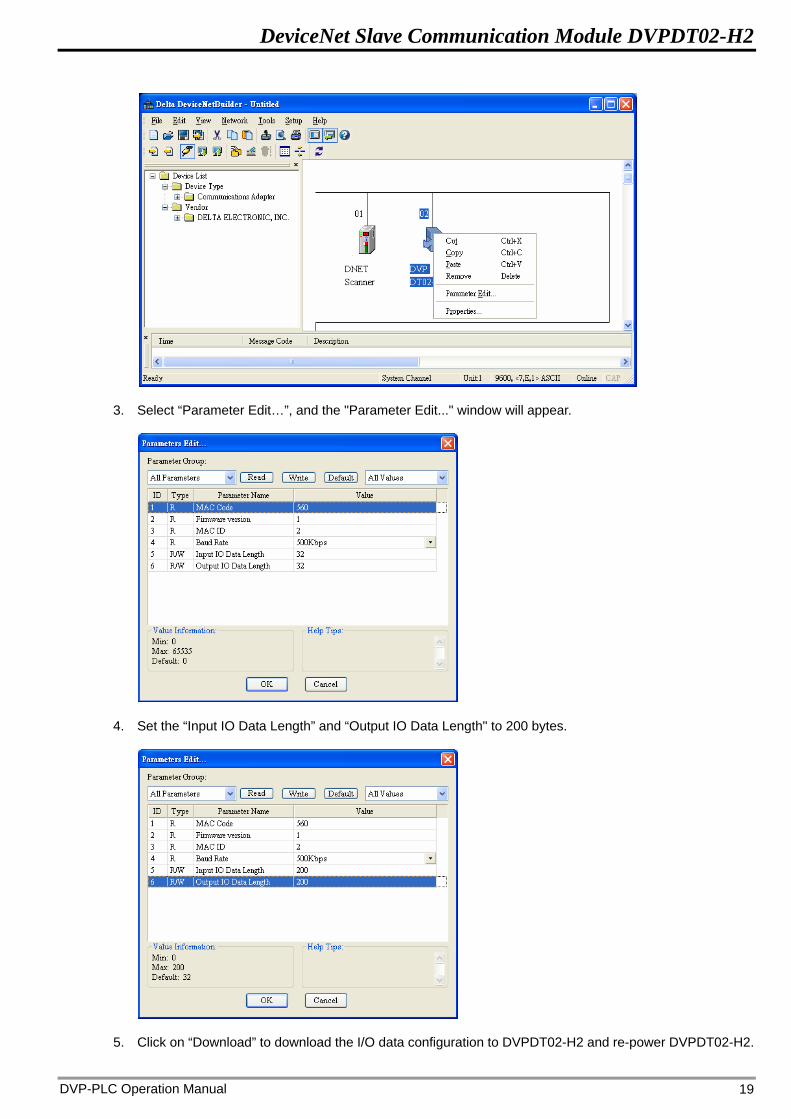
3. Select “Parameter Edit…”, and the "Parameter Edit..." window will appear.
4. Set the “Input IO Data Length” and “Output IO Data Length" to 200 bytes.
5. Click on “Download” to download the I/O data configuration to DVPDT02-H2 and re-power DVPDT02-H2.
DeviceNet Slave Communication Module DVPDT02-H2
DVP-PLC Operation Manual 20
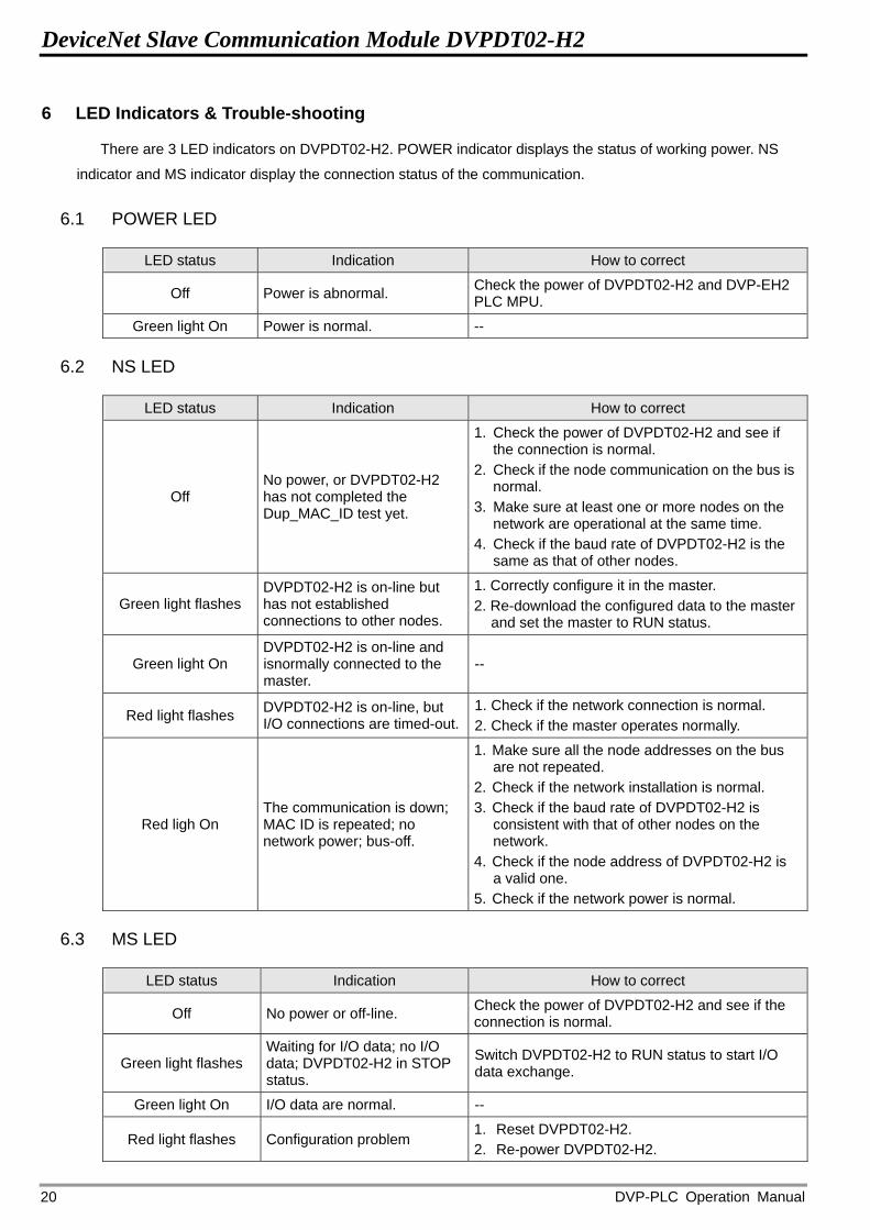
6 LED Indicators & Trouble-shooting
There are 3 LED indicators on DVPDT02-H2. POWER indicator displays the status of working power. NS
indicator and MS indicator display the connection status of the communication.
6.1 POWER LED
LED status Indication How to correct
Off Power is abnormal. Check the power of DVPDT02-H2 and DVP-EH2 PLC MPU.
Green light On Power is normal. --
6.2 NS LED
LED status Indication How to correct
Off No power, or DVPDT02-H2 has not completed the Dup_MAC_ID test yet.
1. Check the power of DVPDT02-H2 and see if the connection is normal.
2. Check if the node communication on the bus is normal.
3. Make sure at least one or more nodes on the network are operational at the same time.
4. Check if the baud rate of DVPDT02-H2 is the same as that of other nodes.
Green light flashes DVPDT02-H2 is on-line but has not established connections to other nodes.
1. Correctly configure it in the master. 2. Re-download the configured data to the master
and set the master to RUN status.
Green light On DVPDT02-H2 is on-line and isnormally connected to the master.
--
Red light flashes DVPDT02-H2 is on-line, but I/O connections are timed-out.
1. Check if the network connection is normal. 2. Check if the master operates normally.
Red ligh On The communication is down; MAC ID is repeated; no network power; bus-off.
1. Make sure all the node addresses on the bus are not repeated.
2. Check if the network installation is normal. 3. Check if the baud rate of DVPDT02-H2 is
consistent with that of other nodes on the network.
4. Check if the node address of DVPDT02-H2 is a valid one.
5. Check if the network power is normal.
6.3 MS LED
LED status Indication How to correct
Off No power or off-line. Check the power of DVPDT02-H2 and see if the connection is normal.
Green light flashes Waiting for I/O data; no I/O data; DVPDT02-H2 in STOP status.
Switch DVPDT02-H2 to RUN status to start I/O data exchange.
Green light On I/O data are normal. --
Red light flashes Configuration problem 1. Reset DVPDT02-H2. 2. Re-power DVPDT02-H2.
DeviceNet Slave Communication Module DVPDT02-H2
DVP-PLC Operation Manual 21
LED status Indication How to correct
Red light On Hardware error 1. Find out the cause of error in CR#251. 2. Send back to the manufacturer for repair if
necessary.
6.4 NS LED + MS LED
LED status
NS LED MS LED Indication How to correct
Off Off No power Check the power of DVPDT02-H2 and see if the connection is normal.
Off Green light On
DVPDT02-H2 has not completed the Dup_MAC_ID test yet.
Make sure at least one or more nodes on the network is operational at the same time, and its baud rate is the same as that of DVPDT02-H2.
Red light On Red light flashes No network power
1. Check if the network cable is correctly connected to DVPDT02-H2.
2. Check if the network power works normally.
Red ligh On Green light On
Dup_MAC_ID test has failed; bus-off
7 Make sure DVPDT02-H2 has a unique address.
8 Re-power DVPDT02-H2.
Red light On Red light On Hardware error Send your DVPDT02-H2 back to the manufacturer for repair.
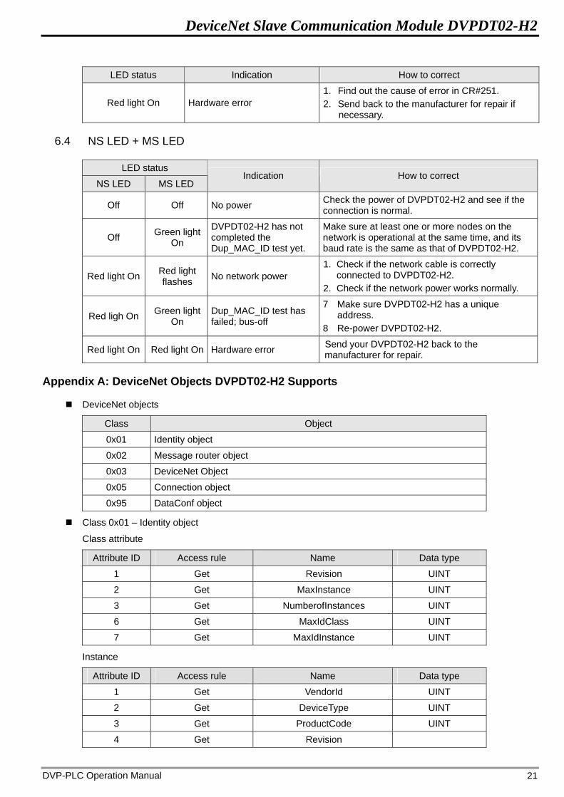
Appendix A: DeviceNet Objects DVPDT02-H2 Supports
DeviceNet objects
Class Object
0x01 Identity object
0x02 Message router object
0x03 DeviceNet Object
0x05 Connection object
0x95 DataConf object
Class 0x01 – Identity object
Class attribute
Attribute ID Access rule Name Data type
1 Get Revision UINT
2 Get MaxInstance UINT
3 Get NumberofInstances UINT
6 Get MaxIdClass UINT
7 Get MaxIdInstance UINT
Instance
Attribute ID Access rule Name Data type
1 Get VendorId UINT
2 Get DeviceType UINT
3 Get ProductCode UINT
4 Get Revision

DeviceNet Slave Communication Module DVPDT02-H2
DVP-PLC Operation Manual 22
Attribute ID Access rule Name Data type MaxRev MinRev
USINT USINT
5 Get Status WORD
6 Get Sn UDINT
7 Get ProdName
StrLen ASCIIStr
USINT
STRING
Common services
Implemented for Service code
Class Instance Service name
0x05 No Yes Reset
0x0E Yes Yes Get_Attribute_Single
Class 0x02 – Message router object
Class attribute
Attribute ID Access rule Name Data type
1 Get Revision UINT
6 Get MaxIdClass UINT
7 Get MaxIdInstance UINT
Instance
Attribute ID Access rule Name Data type
2 Get NumAvailable UINT
3 Get NumActive UINT
Common services
Implemented for Service code
Class Instance Service name
0x0E Yes Yes Get_Attribute_Single
Class 0x03 – DeviceNet object
Class attribute
Attribute ID Access rule Name Data type
1 Get Revision UINT
Instance attribute
Attribute ID Access rule Name Data type
1 Get MACID USINT
2 Get BaudRate USINT
3 Get/Set BusofInterrupt BOOL
4 Get/Set BusofCounter USINT
5 Get AllocationInfo
AllocationChoice MasterNodeAddress
BYTE USINT
6 Get MACIDSwitchChanged BOOL
DeviceNet Slave Communication Module DVPDT02-H2
DVP-PLC Operation Manual 23
Attribute ID Access rule Name Data type
7 Get BaudRateSwitchChanged BOOL
8 Get MACIDSwitchValue USINT
9 Get BaudRateSwitchValue USINT
Common services
Implemented for Service code
Class InstanceService name
0x0E Yes Yes Get_Attribute_Single
0x10 No Yes Set_Attribute_Single
0x4B No Yes Allocate_Master/Slave_Connection_Set
0x4C No Yes Release_Master/Slave_Connection_Set
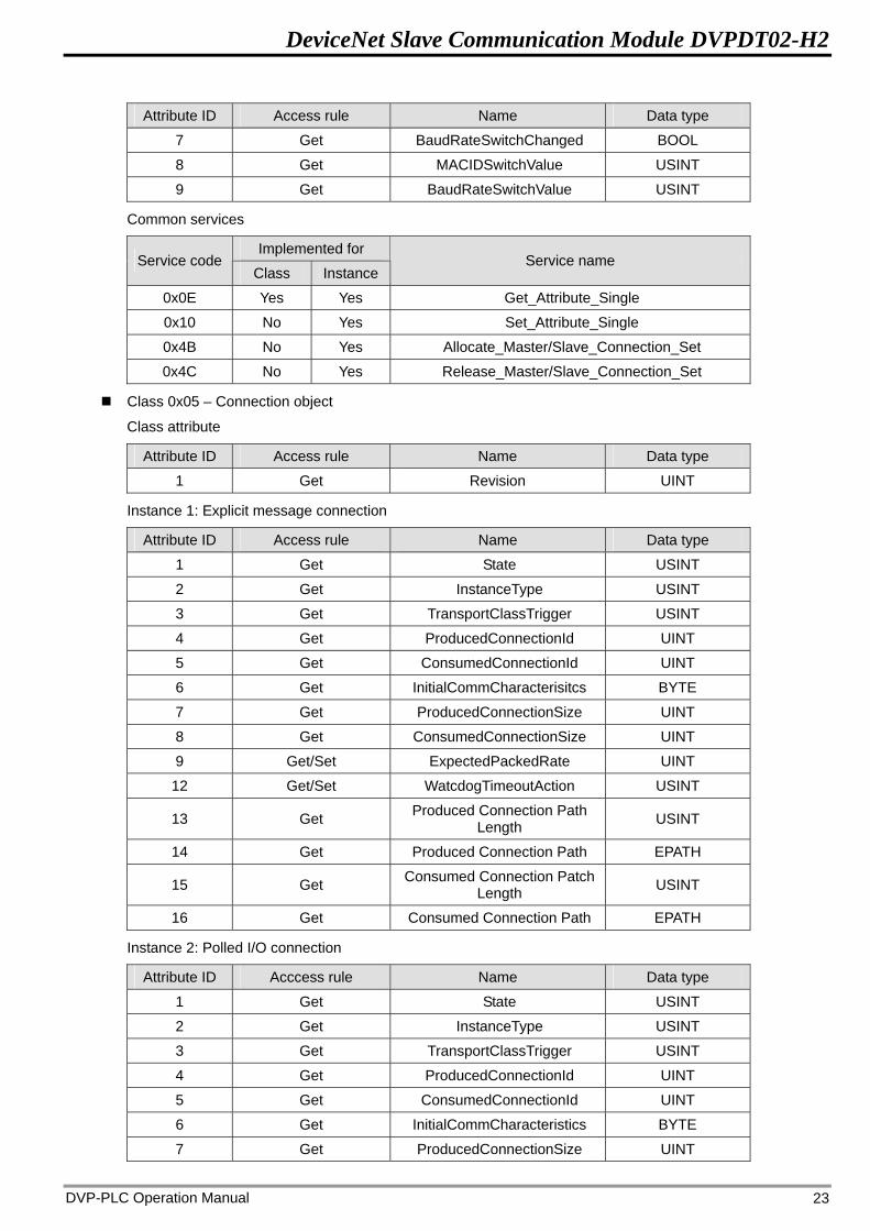
Class 0x05 – Connection object
Class attribute
Attribute ID Access rule Name Data type
1 Get Revision UINT
Instance 1: Explicit message connection
Attribute ID Access rule Name Data type
1 Get State USINT
2 Get InstanceType USINT
3 Get TransportClassTrigger USINT
4 Get ProducedConnectionId UINT
5 Get ConsumedConnectionId UINT
6 Get InitialCommCharacterisitcs BYTE
7 Get ProducedConnectionSize UINT
8 Get ConsumedConnectionSize UINT
9 Get/Set ExpectedPackedRate UINT
12 Get/Set WatcdogTimeoutAction USINT
13 Get Produced Connection Path Length USINT
14 Get Produced Connection Path EPATH
15 Get Consumed Connection Patch Length USINT
16 Get Consumed Connection Path EPATH
Instance 2: Polled I/O connection
Attribute ID Acccess rule Name Data type
1 Get State USINT
2 Get InstanceType USINT
3 Get TransportClassTrigger USINT
4 Get ProducedConnectionId UINT
5 Get ConsumedConnectionId UINT
6 Get InitialCommCharacteristics BYTE
7 Get ProducedConnectionSize UINT
DeviceNet Slave Communication Module DVPDT02-H2
DVP-PLC Operation Manual 24
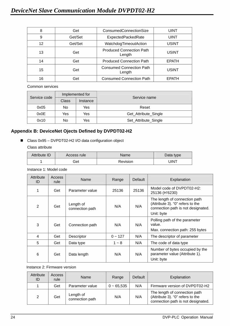
8 Get ConsumedConnectionSize UINT
9 Get/Set ExpectedPackedRate UINT
12 Get/Set WatchdogTimeoutAction USINT
13 Get Produced Connection Path Length USINT
14 Get Produced Connection Path EPATH
15 Get Consumed Connection Path Length USINT
16 Get Consumed Connection Path EPATH
Common services
Implemented for Service code
Class Instance Service name
0x05 No Yes Reset
0x0E Yes Yes Get_Attribute_Single
0x10 No Yes Set_Attribute_Single
Appendix B: DeviceNet Ojects Defined by DVPDT02-H2
Class 0x95 – DVPDT02-H2 I/O data configuration object
Class attribute
Attribute ID Access rule Name Data type
1 Get Revision UINT
Instance 1: Model code
Attribute ID
Access rule Name Range Default Explanation
1 Get Parameter value 25136 25136 Model code of DVPDT02-H2: 25136 (H’6230)
2 Get Length of connection path N/A N/A
The length of connection path (Attribute 3). “0” refers to the connection path is not designated. Unit: byte
3 Get Connection path N/A N/A Polling path of the parameter value. Max. connection path: 255 bytes
4 Get Descriptor 0 ~ 127 N/A The descriptor of parameter
5 Get Data type 1 ~ 8 N/A The code of data type
6 Get Data length N/A N/A Number of bytes occupied by the parameter value (Attribute 1). Unit: byte
Instance 2: Firmware version
Attribute ID
Access rule Name Range Default Explanation
1 Get Parameter value 0 ~ 65,535 N/A Firmware version of DVPDT02-H2
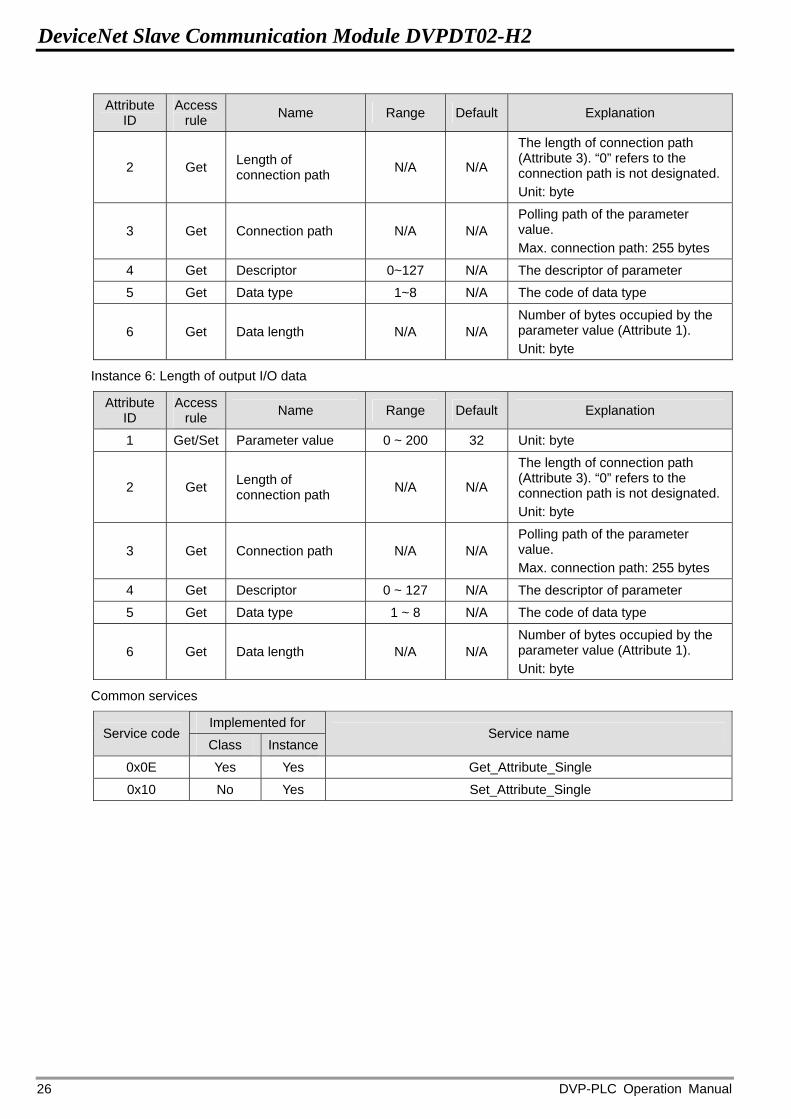
2 Get Length of connection path N/A N/A
The length of connection path (Attribute 3). “0” refers to the connection path is not designated.

DeviceNet Slave Communication Module DVPDT02-H2
DVP-PLC Operation Manual 25
Attribute ID
Access rule Name Range Default Explanation
Unit: byte
3 Get Connection path N/A N/A Polling path of the parameter value. Max. connection path: 255 bytes
4 Get Descriptor 0 ~ 127 N/A The descriptor of parameter
5 Get Data type 1 ~ 8 N/A The code of data type
6 Get Data length N/A N/A Number of bytes occupied by the parameter value (Attribute 1). Unit: byte
Instance 3: Node address
Attribute ID
Access rule Name Range Default Explanation
1 Get Parameter value 0 ~ 63 N/A Node address of DVPDT02-H2
2 Get Length of connection path N/A N/A
The length of connection path (Attribute 3). “0” refers to the connection path is not designated. Unit: byte
3 Get Connection path N/A N/A Polling path of the parameter value. Max. connection path: 255 bytes
4 Get Descriptor 0 ~ 127 N/A The descriptor of parameter
5 Get Data type 1 ~ 8 N/A The code of data type
6 Get Data length N/A N/A Number of bytes occupied by the parameter value (Attribute 1). Unit: byte
Instance 4: Serial transmission speed
Attribute ID
Access rule Name Range Default Explanation
1 Get Parameter value 0 ~ 2 0 Communication speed of DVPDT02-H2
2 Get Length of connection path N/A N/A
The length of connection path (Attribute 3). “0” refers to the connection path is not designated. Unit: byte
3 Get Connection path N/A N/A Polling path of the parameter value. Max. connection path: 255 bytes
4 Get Descriptor 0 ~ 127 N/A The descriptor of parameter
5 Get Data type 1 ~ 8 N/A The code of data type
6 Get Data length N/A N/A Number of bytes occupied by the parameter value (Attribute 1). Unit: byte
Instance 5: Length of input I/O data
Attribute ID
Access rule Name Range Default Explanation
1 Get/Set Parameter value 0 ~ 200 32 Unit: byte
DeviceNet Slave Communication Module DVPDT02-H2
DVP-PLC Operation Manual 26
Attribute ID
Access rule Name Range Default Explanation
2 Get Length of connection path N/A N/A
The length of connection path (Attribute 3). “0” refers to the connection path is not designated. Unit: byte
3 Get Connection path N/A N/A Polling path of the parameter value. Max. connection path: 255 bytes
4 Get Descriptor 0~127 N/A The descriptor of parameter
5 Get Data type 1~8 N/A The code of data type
6 Get Data length N/A N/A Number of bytes occupied by the parameter value (Attribute 1). Unit: byte
Instance 6: Length of output I/O data
Attribute ID
Access rule Name Range Default Explanation
1 Get/Set Parameter value 0 ~ 200 32 Unit: byte
2 Get Length of connection path N/A N/A
The length of connection path (Attribute 3). “0” refers to the connection path is not designated. Unit: byte
3 Get Connection path N/A N/A Polling path of the parameter value. Max. connection path: 255 bytes
4 Get Descriptor 0 ~ 127 N/A The descriptor of parameter
5 Get Data type 1 ~ 8 N/A The code of data type
6 Get Data length N/A N/A Number of bytes occupied by the parameter value (Attribute 1). Unit: byte
Common services
Implemented for Service code
Class Instance Service name
0x0E Yes Yes Get_Attribute_Single
0x10 No Yes Set_Attribute_Single