Update on the WV Miner Location Seismic System 1 WV Miner Seismic System.pdfzThe trapped miners have...
59
Update on the WV Miner Location Seismic System By Keith A. Heasley
Transcript of Update on the WV Miner Location Seismic System 1 WV Miner Seismic System.pdfzThe trapped miners have...

Update on the WV Miner LocationSeismic System
ByKeith A. Heasley

AcknowledgementsCo-Investigators at WVU
Dr. Syd S. PengDr Yi Luo
Co-Investigators at WV OMHS&TMonte HiebRandy Harris

Acknowledgements4 West Mine, Dana Mining Co.
Eric Grimm – SuperintendentBrian Osborn – Sr. Mine EngineerSami Stahle – Mine Engineer
Weir-Jones ConsultingIan Weir Jones - PrincipalBohdan Nedilko – Computer Scientist
Hilti, Inc.Jim Pinkley – Market Manager MiningHayden Whittam – Technical Sales Rep.

DisclaimerThere were a lot of people contributing to this work.
I AM NOT A SEISMOLOGIST
The results from the field test are very preliminary.

ScenarioAn accident has happened in an underground coal mine that has left some number of miners trapped
All communications systems have been compromised and there is no way to determine if there are survivors or exactly where they are.
All operations other than ventilation and rescue have ceased at the mine
The trapped miners have begun signaling on the half-hour by pounding – ten strikes, pause for a count of ten and then ten more strikes, then wait for a half-hour.

Seismic LocationSystem

SeismicityThe waves consists of 2 types:
P waves – primary, compression wavesS Waves – secondary, shear waves
Larger amplitudeSlower (60% of P wave velocity)
Seismic waves travel through the ground (5000 m/s), water (1450 m/s), and air (330 m/s).

Geophone

Active Seismics

Passive Seismics

BackgroundIn 1970, the National Academy of Engineering (NAE) reported that a seismic system might be capable of detecting and locating trapped miners.
The miners would strike the roofThe ground vibrations would be recorded by surface geophonesDifference in arrival times at different geophones would be used to locate the miners

BackgroundIn 1971 and 1972, Westinghouse Electric Co. built and tested such a system.
Under favorable conditions, the system worked.
At actual disaster sites, the background noise generated by surface rescue operations masked any miner generated signals.
Thus a time specifically designated for seismic “listening” must be allocated and enforced.
Detection Distances

MSHA Seismic Location SystemDeveloped in the 70’sUses 7 sub-arrays of 7 geophones each.Capable of detecting miners up to 1500 ft deep

Equipment Truck

Generator Truck & Equipment Trailer

MSHA Seismic Location SystemOlder electronic technology –70’s“There have been some modifications over the years, but it is generally agreed that it is in need of replacement”

Since the 70’sGreatly Enhanced Computer Technology
Digital transmission and storageof seismic signalsDigital filtering and triggering for enhanced resolution.

Seismic Monitoring Systems
Nickels mines in Sudbury CanadaDeep Gold mines of South AfricaResearch Tool
Australian coal minesUS coal mines – NIOSHUS limestone mines - NIOSH

Willow Creek Willow Creek –– Seismic SystemSeismic System--

Schematic of Seismic SystemSchematic of Seismic System
Digitizer
Fiber-OpticNetwork
Spread SpectrumRadio Telemetry
Underground Geophones
UndergroundData Acquisition
Data AcquisitionSurface
Main DataAnalysis
Surface Geophones
Digitizer
Digitizer
Digitizer

GeophoneGeophone
Surface StationSurface Station
PrePre--AmplifierAmplifier

Radio Transmitter SiteRadio Transmitter Site
Solar PanelsSolar Panels
Radio AntennaeRadio Antennae
Batteries andBatteries andRadio TransmittersRadio Transmitters

Underground StationUnderground Station
GeophoneGeophonePrePre--AmplifierAmplifier

Seismic Events at Willow Creek MineSeismic Events at Willow Creek Mine

Present Research

MandateWest Virginia Mine Safety Technology Task Force report (May 29th ,2006):
“The director shall provide portable seismic locating systems at each regional office (4) for use in locating trapped miners.”“Each office will maintain a trained staff that shall, upon notification from Homeland Security Office, be capable of delivering the system to the mine site and to deploy the system immediately and without delay.”“These persons shall practice with the said systems at least annually at different mine sites.”

Research ObjectivesDetermine and Acquire the “best available”seismic location system for trapped miners.Conduct field tests to determine the capabilities and limitations of the system
Depths, DistancesGeologyMultiple seams, gob areas, etc.
Long Term: Help develop the hardware and software for a practical location system for trapped miners.

Technology Requirements
PortableSmall enough to carry in regular vehiclesRequire no power beyond portable batteries
Easily DeployedCan be deployed in 60 minutesCan be moved quicklyCan interconnect with additional unitsRugged enough to survive repeated use.

Technology Requirements
Simple to OperateSoftware should be automated enough for on-site technicianProduce accurate results in real-timeAbility to produce mapsAbility to save and transmit seismic data to consulting seismic experts to assist in interpretation

Successful Location “Location accuracies to within one or two coal pillars, and even to within dimensions of a working section, when used in conjunction with a good mine map, will be extremely valuable and, in many cases, be more than sufficient to direct the efforts of both in-mine rescue crews and surface drilling crews.”

Field Test Site4 West Mine, Dana Mining Co. of PA, Inc.
North of Morgantown and the PA border
Off the Mt Morris Exit (Exit #1) of interstate 79

Field Test Site

Field Test Site

Test Layout

Downhole Geophone

Seismic EquipmentGeospace 32CT geophones
Terrasciences 24 channel, 24 bit digitizer sampling at 2 kHz
Portable PC & car battery

Test ProtocolSignaling devices:
Hilti DX76, Hilti DX460, Hilti DX462, 8 lb sledge hammer, and crib block
Signaling Locations:Roof bolt, roof rock, and rib
5 impacts, wait 30 seconds, next device
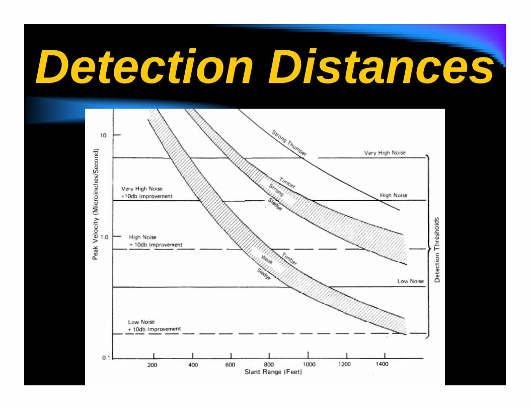
Test Results
14045Roof RockBlock14025Roof RockHammer7080Roof BoltCrib Block7080Roof RockCrib Block7045Roof RockHammer080Roof BoltCrib Block0100Roof RockCrib Block060Roof BoltHammer060Roof RockHammer
Offset (ft)PPV (um/s)LocationDevice

Seismic SignalGeophone #6, Z-Axis - Crib Block on Roof Rock - 0 Feet Offset
-0.0001
-0.00005
0
0.00005
0.0001
11.00 12.00 13.00 14.00 15.00 16.00 17.00 18.00 19.00 20.00 21.00
Time (secs)
velo
city
(m/s
ec)
Geophone #6, Z-Axis - Crib Block on Roof Rock - 0 Feet Offset
-0.0001
-0.00005
0
0.00005
0.0001
15.70 15.75 15.80 15.85 15.90 15.95 16.00 16.05 16.10
Time (secs)
velo
city
(m/s
ec)

Distance
Geophone #6, Z Axis - Crib Block on Roof Rock - 70 Feet Offset
-0.0001
-0.00005
0
0.00005
0.0001
11.00 12.00 13.00 14.00 15.00 16.00 17.00 18.00 19.00 20.00 21.00
Time (secs)
velo
city
(m/s
ec)
Geophone #6, Z-Axis - Crib Block on Roof Rock - 0 Feet Offset
-0.0001
-0.00005
0
0.00005
0.0001
11.00 12.00 13.00 14.00 15.00 16.00 17.00 18.00 19.00 20.00 21.00
Time (secs)
velo
city
(m/s
ec)
Geophone #6, Z-Axis - Crib Block on Roof Rock - 140 Feet Offset
-0.0001
-0.00005
0
0.00005
0.0001
6.00 7.00 8.00 9.00 10.00 11.00 12.00 13.00 14.00 15.00 16.00 17.00
Time (secs)
velo
city
(m/s
ec)

Z-Axis – X-AxisGeophone #6, Z-Axis - Crib Block on Roof Rock - 0 Feet Offset
-0.0001
-0.00005
0
0.00005
0.0001
11.00 12.00 13.00 14.00 15.00 16.00 17.00 18.00 19.00 20.00 21.00
Time (secs)
velo
city
(m/s
ec)
Geophone #6, X-Axis - Crib Block on Roof Rock - 0 Feet Offset
-0.0001
-0.00005
0
0.00005
0.0001
11.00 12.00 13.00 14.00 15.00 16.00 17.00 18.00 19.00 20.00 21.00
Time (secs)
velo
city
(m/s
ec)

Buried - SurfaceGeophone #6, Z-Axis - Crib Block on Roof Rock - 0 Feet Offset
-0.0001
-0.00005
0
0.00005
0.0001
11.00 12.00 13.00 14.00 15.00 16.00 17.00 18.00 19.00 20.00 21.00
Time (secs)
velo
city
(m/s
ec)
Geophone #2, Z-Axis - Crib Block on Roof Rock - 0 Feet Offset
-0.0001
-0.00005
0
0.00005
0.0001
11.00 12.00 13.00 14.00 15.00 16.00 17.00 18.00 19.00 20.00 21.00
Time (secs)
velo
city
(m/s
ec)

UnFiltered - Filtered
Geophone #6, Z-Axis - Crib Block on Roof Rock - 0 Feet Offset
-0.0001
-0.00005
0
0.00005
0.0001
11.00 12.00 13.00 14.00 15.00 16.00 17.00 18.00 19.00 20.00 21.00
Time (secs)
velo
city
(m/s
ec)
Geophone #6, Z-Axis - Crib Block on Roof Rock - 0 Feet Offset
-0.0001
-0.00005
0
0.00005
0.0001
11.00 12.00 13.00 14.00 15.00 16.00 17.00 18.00 19.00 20.00 21.00
Time (secs)
velo
city
(m/s
ec)

Test ResultsCrib Block on the Roof Rock appeared to be the strongest
-> Crib on Roof Bolt-> Hammer on Roof Rock-> Hammer on Roof Bolt
Hilti tools were not very detectable?Higher Frequencies?
Good detection out to 140 ftNot at 210 ft

Test ResultsMostly Vertical Ground vibration
Buried geophones provided about twice the peak particle velocity
Better connection?Less soil?
Increase in distance not totally responsible for signal attenuation
Polarized source?Horizontal bedding?

ConclusionsUse a crib block on the roof rock
An effective trapped miner, seismic location system is achievable.

Future WorkThorough analyze data
Quantify detection strengthApply filtering
Test at “deep” mineMultiple-seamGob areas
Acquire “state-of-the-art” system

Seismic Signaling

Supporting Literature“Mine Safety Recommendations,” Report to the Director of the Office of Miners Health, Safety and Training, West Virginia Mine Safety Technology Task Force, May 29th, 2006.
WV Mine Safety Roundtable on Seismic Miner Location, June 28th, 2006
“The Sago Mine Disaster,” A Preliminary Report to Governor Joe Manchin III, by J. Davitt McAteer and associates, July, 2006

Ground RulesSystem hardware suitable for rapid field deploymentSystem use present state-of-the-art equipmentSystem operates from the surface.System is self-containedSystem is compatible with overall rescue effortReadily available signal sourcesLikely area of trapped miners is knownSurface team will have mine maps.

Field Test SiteNear the top of a ridge for maximum overburden (441 ft)
Over the supply entry in an 11 entry main.

Test Layout4 geophone sites in a “T”
A “surface” geophone at each site
A “downhole” geophone at site 1 & 2

Successful Location Within 100 ft
Favorable, Controlled SituationsArrival times can be estimated within 1- 5 msLayering and seismic velocities can be specified within 5%

Signal Improvement Bandpass FilteringBurial of SensorsSubarrays
Size OptimizationDelayed or Direct SumWeighted Sum

MSHA Seismic Location SystemConsists of 3 trucks
Equipment truck – recorders and filtersGenerator truckTrailer – geophone, cables & supplies

Areas for DevelopmentPre-deployed systemsData format standardizationImproved signaling methodsSignaling from within sheltersIdeal set of available of geologic informationOptions for remote analysisPreloaded mine mapsOptions for use in other emergencies.

Field Test Site

BackgroundOutcomes, Westinghouse Electric System tests.
System was all undergroundSignals could be detected up to 1000 ft, but not 1500 ft, away.Point-anchor bolts caused a 100 Hz resonance.A band-pass filter range of 20-200 Hz worked best.Velocities of 4,200-5,000 m/s were observed (with second arrivals at 1,700 m/s).An array of 6 geophones did not work any better than a single phone.