Update on Feasibility of UV LEDs in a Spacecraft ...
12
ICES-2020-566 Copyright © 2020 KBR Inc. Trade names and trademarks are used in this report for identification only. Their usage does not constitute an official endorsement, either expressed or implied, by the National Aeronautics and Space Administration. Update on Feasibility of UV LEDs in a Spacecraft Wastewater Application Susan N. Gilbert 1 , Audry Almengor 2 , Jacob Harris 3 KBR, Houston, TX, 77058, U.S.A Anthony Hanford 4 HX5, LLC, Houston, TX, 77058, U.S.A and Niklas Adam 5 , Michael R. Callahan 6 , C. Mark Ott 7 NASA Johnson Space Center, Houston, TX, 77058, U.S.A As the National Aeronautics and Space Administration (NASA) expands its scope and begins to venture into long-duration, manned space flights, the function and maintenance of spacecraft water systems becomes increasingly critical and difficult. New mission requirements limit opportunities for resupply and demand extended periods of uncrewed operations. Based on lessons learned from the International Space Station (ISS), one particular challenge of future spacecraft water systems will be maintaining adequate microbial control, especially in water subsystems and component-level elements, where effective long-duration biocontrol strategies do not currently exist. To ensure the reliability and redundancy in these systems, innovative technologies will be needed to ensure mission success. After proving feasibility of commercial-off-the-shelf (COTS) devices in flow-through applications in 2018, work focused on utilizing ultraviolet (UV) light emitting diodes (LEDs) in a wastewater tank application. This paper gives an update on the tank testing that has been performed to date. Using this technology may reduce the need for consumable resupply, such as filters or biocides, and minimize crew time to make the repairs on exhausted and/or compromised systems. The ultimate rationale behind developing a UV disinfection system is to increase the stability of water systems as requirements for sterility and microbial control become more stringent for deep space missions. The resulting data from this study will be used to narrow down possible technology demonstrations for selected ISS locations to assess the use of UV technology on future exploration-class spacecraft systems. Nomenclature °C = degrees Celsius CFD = computational fluid dynamics CFU = colony forming units CHX = condensing heat exchanger 1 Project Engineer, KBR – Human Systems Engineering Department, KBR (2400 NASA Pkwy) 2 Microbiologist, JES Tech – Biomedical and Environment Research Department, KBR (2101 NASA Pkwy) 3 Microbiologist, JES Tech – Biomedical and Environment Research Department, KBR (2101 NASA Pkwy) 4 Analyst – JETS Contract, Crew and Thermal Systems Division, Mail Stop: JE-5EA (2224 Bay Area Blvd) 5 UV Disinfection Lead – NASA JSC, Crew and Thermal Systems Division, Mail Stop: EC3 (2101 NASA Pkwy) 6 Water Technology Lead – NASA JSC, Crew and Thermal Systems Division, Mail Stop: EC3 (2101 NASA Pkwy) 7 Microbiology Laboratory Lead – NASA JSC, Biomedical Research and Environmental Sciences Directorate, Mail Stop: SK4 (2101 NASA Pkwy)
Transcript of Update on Feasibility of UV LEDs in a Spacecraft ...

ICES-2020-566
Copyright © 2020 KBR Inc.
Trade names and trademarks are used in this report for identification only. Their usage does not constitute an official
endorsement, either expressed or implied, by the National Aeronautics and Space Administration.
Update on Feasibility of UV LEDs in a Spacecraft
Wastewater Application
Susan N. Gilbert1, Audry Almengor2, Jacob Harris3
KBR, Houston, TX, 77058, U.S.A
Anthony Hanford4
HX5, LLC, Houston, TX, 77058, U.S.A
and
Niklas Adam5, Michael R. Callahan6, C. Mark Ott7
NASA Johnson Space Center, Houston, TX, 77058, U.S.A
As the National Aeronautics and Space Administration (NASA) expands its scope and
begins to venture into long-duration, manned space flights, the function and maintenance of
spacecraft water systems becomes increasingly critical and difficult. New mission
requirements limit opportunities for resupply and demand extended periods of uncrewed
operations. Based on lessons learned from the International Space Station (ISS), one
particular challenge of future spacecraft water systems will be maintaining adequate
microbial control, especially in water subsystems and component-level elements, where
effective long-duration biocontrol strategies do not currently exist. To ensure the reliability
and redundancy in these systems, innovative technologies will be needed to ensure mission
success. After proving feasibility of commercial-off-the-shelf (COTS) devices in flow-through
applications in 2018, work focused on utilizing ultraviolet (UV) light emitting diodes (LEDs)
in a wastewater tank application. This paper gives an update on the tank testing that has been
performed to date. Using this technology may reduce the need for consumable resupply, such
as filters or biocides, and minimize crew time to make the repairs on exhausted and/or
compromised systems. The ultimate rationale behind developing a UV disinfection system is
to increase the stability of water systems as requirements for sterility and microbial control
become more stringent for deep space missions. The resulting data from this study will be used
to narrow down possible technology demonstrations for selected ISS locations to assess the use
of UV technology on future exploration-class spacecraft systems.
Nomenclature
°C = degrees Celsius
CFD = computational fluid dynamics
CFU = colony forming units
CHX = condensing heat exchanger
1 Project Engineer, KBR – Human Systems Engineering Department, KBR (2400 NASA Pkwy) 2 Microbiologist, JES Tech – Biomedical and Environment Research Department, KBR (2101 NASA Pkwy) 3 Microbiologist, JES Tech – Biomedical and Environment Research Department, KBR (2101 NASA Pkwy) 4 Analyst – JETS Contract, Crew and Thermal Systems Division, Mail Stop: JE-5EA (2224 Bay Area Blvd) 5 UV Disinfection Lead – NASA JSC, Crew and Thermal Systems Division, Mail Stop: EC3 (2101 NASA Pkwy) 6 Water Technology Lead – NASA JSC, Crew and Thermal Systems Division, Mail Stop: EC3 (2101 NASA Pkwy) 7 Microbiology Laboratory Lead – NASA JSC, Biomedical Research and Environmental Sciences Directorate, Mail
Stop: SK4 (2101 NASA Pkwy)

International Conference on Environmental Systems
2
COTS = commercial-off-the-shelf
DDT&E = development, design, test, and evaluation
DI = deionized water
EMU = Extravehicular Mobility Unit
EVA = extravehicular activity
HV = hand valve
ISS = International Space Station LED = light emitting diode
LEO = low Earth orbit
MCV = microbial check valve
mL = milliliter
MSFC = Marshall Space Flight Center
N = final bacterial concentration [CFU/mL]
NASA = National Aeronautics and Space Administration
nm = nanometer
NO = initial bacterial concentration [CFU/mL]
OGA = Oxygen Generation Assembly
OGS = Oxygen Generation System
ORU = orbital replacement unit
POU = point-of-use (device)
PWD = Potable Water Dispenser
QD = quick disconnect
R2A = Reasoner’s 2A agar
SOA = state-of-the-art
UPA = Urine Processor Assembly
UV = ultraviolet
W = Watts
WAL = Water Analysis Laboratory
WPA = Water Processor Assembly
I. Introduction and Background
s the National Aeronautics and Space Administration (NASA) expands its scope and begins to venture into long-
duration, manned space flights, water reclamation systems become increasingly critical and difficult to maintain.
Visiting vehicles can no longer easily replenish water once spaceflight moves beyond low Earth orbit (LEO) and into
deep space. Deep space transport vehicles will need to contain and reuse all life support essentials (e.g. air and water)
for the duration of the flight, which for Mars could last up to 2-3 years. Looking specifically at water, the reclamation
system must perform flawlessly for the entire mission by reclaiming wastewater and continuously producing safe,
clean drinking water. Several subsystems and components will need breakthrough upgrades in order to achieve this
feat. An area of significant concern for future missions, and one that has presented challenges for the International
Space Station, has been bacterial control, especially in specific gap areas of the water system lacking biocontrol
strategies. Whether concerns over acute failure such as system clogging, or the implementation of multiple
antimicrobial strategies to protect equipment and crew, improving the reliability of the system has generally come at
the cost of added consumable mass, e.g., filters and/or chemical biocide addition. For deep space missions, a complete
and effective long-term biocontrol strategy is needed.
In a previous NASA study, we described a series of feasibility studies conducted to investigate the potential
benefits of ultraviolet (UV) light emitting diodes (LED) disinfection technology for spacecraft applications.1 From the
study, a number of potentially high value applications were identified. These included: (1) In-Tank applications to
prevent biofilm growth, particularly in the wastewater storage tank of the Water Processor Assembly (WPA), (2) a
point-of-use (POU) device to replace the filter at the end of the Potable Water Dispenser (PWD), (3) a microbial check
valve (MCV) to maintain microbial isolation between processed and unprocessed sides of the WPA recirculation loop,
and (4) for biocontrol in continuous recirculation loops where traditional biocides may not be applicable, e.g., the
oxygen generation system (OGS) and extravehicular activity (EVA) suit loop. In this paper, we describe continued
development of UV-LED technology for in-tank biofilm control, progress on proof-of-concept testing, and results
accomplished to date.
A

International Conference on Environmental Systems
3
II. Current Understanding of the In-Tank Problem
Based on operational experience on the ISS, the formation and release of biofilm from the WPA wastewater tank
has led to at least one clogging event of downstream water processing components.2,3,4 The wastewater collection tank
itself is a bellows-style tank that is a component of the wastewater storage orbital replacement unit (ORU) within the
WPA. The tank function is to store wastewater prior to delivery and processing through the WPA treatment hardware
to reclaim water to the potable standard. Wastewater received by the tank includes: (1) distillate from the urine
processor assembly (UPA), (2) humidity condensate from the condensing heat exchanger (CHX) and product water
from the Sabatier Carbon Dioxide Reduction Reactor. During the last known clogging event, biofilm aggregates
resulted in the costly replacement of the inlet separator and process pump5. The root cause of the system failure is
believed to have been associated with changes to the nominal tank fill and draw operations3. In prior operations, a
“short” stroke cycling event of the bellows was implemented to reduce the risk of overfilling the tank. Fill and draw
of the tank under this operational condition, is believed to allow gas and biofilm accumulate in the interstices of
bellows folds and tank walls. When operations required the tank to undergo large fill and draw cycles, the longer
stroke of the bellows is believed to have caused the accumulated biofilm to sluff-off and enter the down-stream process
flow, clogging the downstream filter. Currently, the risk of biofilm sloughing is managed through restrictions on how
the bellows tank is cycled.6 Specifically, long stroke fill and draw is employed continuously, constantly disturbing the
biofilm, thus preventing large biofilm accumulations. Figure 1 provides a depiction of the WPA wastewater tank and
the operation that led to biofilm accumulation and release.
III. Materials & Methods
A. UV Tank Concepts – Pre-feasibility As a first step in the development of a tank-based UV concept, a “pre-feasibility” trade study was conducted. In
pre-feasibility a set of baseline, assumptions and technical specifications were established. The pre-feasibility
considered the design approach, materials, and potential vendors that might be considered in the development of UV
tank technology. Three concepts for UV tank applications were developed and ultimately down selected to two. The
specific concepts are described later, but generally fell into two categories: (1) direct UV irradiation of or through the
tank walls, and (2) continuous and/or intermittent recirculation of the tank volume through an exterior UV device.
B. Proof-of-Concept Testing For the two tank concepts selected, the technical risks and design considerations were incorporated within a
development test matrix designed to demonstrate early proof-of-concept, tease out developmental risks, and develop
specifications and requirements to advance the system concepts to higher fidelity prototypes. In general, the matrix
a) b) c)
Figure 1. WPA wastewater storage tank (a). WPA wastewater tank under nominal operations: short fill (left) and short draw (right). Biofilm and air accumulate on bellows and tank walls, but short bellows stroke insufficient to disturb biofilm (b). Wastewater tank under nominal operations: large
fill (left) and large draw (right). Accumulated gas and biofilm on bellows and tank walls are disturbed/released from surface by long bellows stroke,
especially during compression cycle. Risk of air inclusion and biomass clogging on downstream systems increases (c).
International Conference on Environmental Systems
4
included simulations, application fundamentals, and sub-scale system level testing to address objectives such as: (a)
UV dosing and kill efficiency to effect biofilm control, (b) flow, light pattern, and light cycling requirements to effect
UV dosing and biofilm control, (c) controlled bench scale testing to validate models, and (d) small scale application
testing to validate bench scale test, understand system-level challenges, and if deemed feasible, provide a forward path
for continued concept development towards higher fidelity prototype development, design, test and evaluation
(DDT&E). Additional details of the test components are provided below.
1. Bacterial Comprehension Enhanced bacterial comprehension studies developed a foundational understanding on how to apply UV
disinfection technology towards microbial control in a tank environment. Based on the proposed tank concepts, three
studies were identified. The first study characterized biofilm formation of the bacteria commonly isolated from the
ISS WPA wastewater tank. This study was necessary because of limited data on biofilm formation of these specific
organisms. The second study was a UV cycling test, needed for the within walls direct irradiation tank concept, to
establish minimal dosing guidelines for controlling biofilm growth. A third study, related to the recirculating UV tank
concept, informed how planktonic bacterial populations “regrow” after exposure to an initial UV dose. These studies
helped determine guidelines for how often a tank might need to be recirculated through an external UV device or how
often and for how long the inside of a tank may need to be irradiated to prevent growing bacteria from forming a new
biofilm. For all these studies, the bacteria selected, the techniques used to culture stock solutions, and the ersatz
solutions for performing the tests have all been described in a previous UV study.1 In short, a consortium of bacteria,
denoted as the “Fab 5”, was chosen based on its prevalence in water systems aboard the ISS, specifically within the
WPA wastewater tank. The exception being P. aeruginosa, which was chosen for its role as a model-organism for
biofilm formation. The other species included in the Fab 5 were: Ralstonia insidiosa, Burkholderia multivorans,
Cupriavidus metallidurans, Methylobacterium fujisawaense, and Pseudomonas aeruginosa. These bacteria are known
to form biofilms. The ersatz solution used was the WPA influent water originally created at Marshall Space Flight
Center (MSFC), which provides an analogue of the chemical constituents found in the WPA wastewater tank.7 In
some studies, the WPA effluent ersatz, also developed by MSFC, was used. A brief description of the bacterial tests
is provided below.
For sample analysis, biofilms were enumerated by rinsing coupons with 10 mL sterile Butterfield’s phosphate
buffer, swabbing the UV-irradiated surface of the coupon with sterile polyester swabs, breaking off the swabs into 3
mL sterile Butterfield’s phosphate buffer, mixing vortically for 1 minute, sonicating for 1 minute, mixing vortically
for an additional minute, and spread plating 100 µL of the suspension or dilutions onto Reasoner’s 2A (R2A) agar in
triplicate. Bacteria were allowed to grow at 35°C for 7 days before counting the colonies. Microscopy of coupons was
performed by rinsing the coupons with 10 mL sterile Butterfield’s phosphate buffer, covering the coupon with a
SYTO®9/propidium iodide solution (FilmTracer™ LIVE/DEAD Biofilm Viability Kit, Life Technologies) for 20
minutes, rinsing with deionized water, and then visualizing with a fluorescent microscope (Nikon Eclipse 50i with
fluorescent filters) using a 40X objective (400X overall magnification).
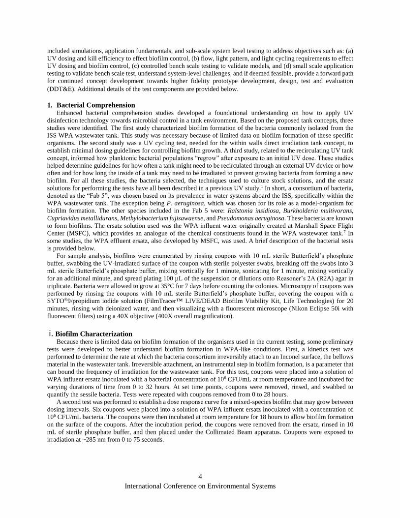
i. Biofilm Characterization Because there is limited data on biofilm formation of the organisms used in the current testing, some preliminary
tests were developed to better understand biofilm formation in WPA-like conditions. First, a kinetics test was
performed to determine the rate at which the bacteria consortium irreversibly attach to an Inconel surface, the bellows
material in the wastewater tank. Irreversible attachment, an instrumental step in biofilm formation, is a parameter that
can bound the frequency of irradiation for the wastewater tank. For this test, coupons were placed into a solution of
WPA influent ersatz inoculated with a bacterial concentration of 106 CFU/mL at room temperature and incubated for
varying durations of time from 0 to 32 hours. At set time points, coupons were removed, rinsed, and swabbed to
quantify the sessile bacteria. Tests were repeated with coupons removed from 0 to 28 hours.
A second test was performed to establish a dose response curve for a mixed-species biofilm that may grow between
dosing intervals. Six coupons were placed into a solution of WPA influent ersatz inoculated with a concentration of
106 CFU/mL bacteria. The coupons were then incubated at room temperature for 18 hours to allow biofilm formation
on the surface of the coupons. After the incubation period, the coupons were removed from the ersatz, rinsed in 10
mL of sterile phosphate buffer, and then placed under the Collimated Beam apparatus. Coupons were exposed to
irradiation at ~285 nm from 0 to 75 seconds.

International Conference on Environmental Systems
5
ii.Collimated Beam – Cycle Testing The collimated beam – cycling tests were used to determine the UV exposure intervals required to suppress biofilm
formation. Optical modeling can use these parameters as inputs for the minimum dose requirement when designing
an array to target microbes in a wastewater tank application. Inoculated test fluid was pumped through a coupon
chamber placed directly under the AquiSense PearlLab Beam™. The volumetric size of the ISS wastewater tank and
the coupon chamber were used to scale down the flow from what is observed on ISS to one that can be used for testing,
resulting in similar residence times of fresh bacteria introduced into the system. The coupon chamber contained a
quartz window for the UV light to pass through. Within the chamber, a horizontal shelf suspended the coupons in the
test fluid. To quantify growth, bacterial counts were obtained from coupons placed within the coupon chamber at the
start and end of testing. Microscopic images were obtained at the end of testing to visualize the biofilm formation on
the surface of the Inconel coupons. The first test case focused on verifying the feasibility of the UV-C LED technology,
whereas the latter test cases were geared towards optimization. Initially, over the course of 7 days, the LEDs were
powered ON 100% of the time. Afterwards, cycles occurred every 2 hours with the LEDs powered ON for a duration
of 2 to 10 minutes, or every 6 hours with the LEDs powered ON for a duration of 2 minutes. After 7 days, the coupons
were aseptically removed and assessed for biofilm growth either quantitatively or microscopically.
Additionally, interval testing was performed to assess the difference between continuous and cumulative pulsed
UV dosing. More specifically, this test was aimed at determining if the UV dose response is cumulative for bacterial
species that exhibit a non-linear dose response curve (e.g., Methylobacterium fujisawaense). The PearlLab Beam™
collimated UV light at a wavelength of ~285 nm onto a petri dish of WPA influent inoculated with a single bacterial
consortium at 106 CFU/mL. One test delivered sixty 1-second doses every 10 seconds for 10 minutes, whereas the
second test delivered a single 60-second dose.
iii. Collimated Beam – Regrowth Regrowth curves were developed to assess the bacteriostatic effect of UV stimuli. This parameter can be used to
determine the frequency of UV dosing needed to prevent the reestablishment of bacterial populations after an initial
UV dose. These studies were implemented with the AquiSense PearlLab Beam™. The PearlLab Beam™ provided
collimated UV light at a wavelength of ~265 nm onto a petri dish of inoculated test water. Each of the regrowth curves
included a UV dose chosen to yield a 2- to 3-log10 reduction for each bacterial species. The five bacteria were tested
in consortium at a bacterial concentration of 106 CFU/mL in two water qualities (WPA influent ersatz, and WPA
effluent ersatz) at room temperature.
C. Tank Modeling and Prototyping Early tank modelling addressed two purposes. First, a representation of the current bellows-style ISS WPA
wastewater tank was needed to understand both the tank design and flow characteristics for the state-of-the-art (SOA)
system. From there it is possible to overlay the design and/or operational changes that might be needed to begin
prototyping new tank designs and/or prototype system for proof-of-concept testing and future design development.
For these considerations, scaling factors and computational fluid dynamics (CFD) modeling aided in the operational
and design analysis. Finally, COMSOL Multiphysics® ray optical modeling was utilized to understand the design
constraints and behavior of light energy in the system when applying UV ray optics.
IV. Results
A. UV Tank Concepts – Pre-Feasibility
A number of concepts were explored to deliver UV irradiation to the bacteria located within the wastewater tank
during a pre-feasibility study. Through that study, four tank configurations were considered. These configurations
included: (a) placement of the UV device(s) inside the tank itself, (b) locating the UV device(s) within the walls of
the tank, (c) locating the UV device(s) outside the tank in a continuous recirculation loop, and/or (d) some combination
of these UV/Tank arrangements. Of these arrangements, the option placing the UV device(s) inside the tank was ruled
out because the tank is sealed making LED change out difficult to implement. Similarly, placing the UV device(s)
inside the tank would prevent the bellows from fully compressing and/or extending – limiting the tank volume. Finally,
as the UV device(s) themselves would need to be sealed from the working fluid, the overall sealing arrangement of
the full tank assembly was considered to be too complex. The tank recirculation concept was considered the simplest
engineering implementation (Figure 2a). In this configuration, maintenance of the external UV device(s) can be
performed, including LED change out and cleaning of the UV transparent window if fouled, without interfering with
the storage tank operations. In addition, the team had limited information that providing a UV dose to the water prior

International Conference on Environmental Systems
6
to entering and leaving the wastewater tank, as well as during storage via an external recirculation loop, may cause
sufficient damage to the bacteria to prevent biofilm formation.8 The within walls concept (Fig 2b) was considered the
most likely to succeed in controlling the biofilm because the interior tank surface would be in direct “line of sight” to
the UV irradiation. Due to the inefficient nature of LEDs in the UV-C range, where 95% of the electrical input is
converted to heat, thermal concerns such as power draw and heat buildup exist with respect to the potential number
of LEDs required to irradiate all internal surfaces of the wastewater tank.8 From an engineering implementation
standpoint, the concept was considered in between the two other concepts – more challenging than recirculation, but
easier to implement than within the tank. Here the UV device would be located in the tank wall and illuminate through
a UV transparent covering or shell.
B. Biofilm Characterization
Prior to performing the collimated beam – cycling test, which uses intermittent UV dosing, it was necessary to
characterize biofilm formation by the Fab 5 bacteria to determine both the maximum time interval between doses and
a)
b)
Figure 2. UV tank concepts selected for further study – UV “within walls” concept shown with shell (a, left) and without shell (a, right),
and UV in a recirculation loop, shown with shell (b, left) and in cross-section (b, right).

International Conference on Environmental Systems
7
the minimum UV dose needed. The maximum interval
time depends on the kinetics of biofilm formation,
while the minimum UV dosage depends on the dose
response of bacteria within a young biofilm. The first
step in biofilm formation is bacterial attachment. Using
Inconel coupons in a solution of 106 CFU/mL bacteria,
it was found that attachment to the coupon happens
within seconds. Approximately 102 CFU of bacteria
attached per cm2 of coupon at time “0,” despite
rigorous washing of the coupons after inoculation
(Figure 3a). The number of bacteria increased
exponentially for the next 20 hours, probably due to
biofilm growth. Why the numbers drop between 20 and
24 hours is unknown, but the phenomenon was
repeatable. In any case, the results of this experiment
show that biofilm formation will likely occur on
surface between UV exposure periods.
Previous dose response curves of the Fab 5 bacteria
looked solely at planktonic cells.1 Should a young
biofilm start to form between UV exposures, there was
concern that a higher UV dosage would be necessary to
achieve a similar level of inactivation. To test this
theory, biofilms were grown on Inconel coupons
overnight (18 hours) and exposed to varying doses of
UV light. The remaining bacteria were swabbed from
the UV exposed surface and quantified. Results
revealed to achieve a 2-log10 reduction of the biofilm
required a UV dose of 38 mJ/cm2 (Figure 3b).
Referencing a dose response curve of
Methylobacterium, the most UV resistant of the Fab 5,
at ~285 nm from a previous study reveals roughly the
same amount of irradiation to achieve the same 2-log10
reduction.1 Therefore, early stages of a biofilm do not
require significantly more irradiation than planktonic bacteria. These results were used to guide the selection of a
minimum UV dosage necessary for collimated beam – cycling testing. It was determined that a 90 second dose would
be necessary to achieve a 2-log10 reduction of Methylobacterium fujisawaense in the coupon chambers used in this
test. Therefore, a minimum 2-minute dosage was used in subsequent testing.
C. Collimated Beam – Cycling
Cycling collimated beam testing measures the effectiveness of brief ultraviolet irradiation on a prescribed schedule
as compared to continuous ultraviolet irradiation. After feasibility testing of UV irradiation delivered 100% of the
time, the overall cycle was either 2 hours or 6 hours with irradiated durations between 2 to 10 minutes. Looking at the
microscopic images of when the UV light is continuously on, few cells are able to attach to the surface of the coupon
when exposed to UV (Figure 4a, right), and a well-developed biofilm forms on a control coupon (Figure 4a, left). It
was observed that the biofilm on the control coupon incorporated several dead cells, as evidenced by the yellow color
of the stained biofilm (live/dead stain). This is attributed to the irradiated and control coupon chambers existing within
the same recirculation loop. It is believed that bacteria that passed through the irradiated coupon chamber circled back
and incorporated within the biofilm in the control coupon chamber. Viewing the coupons exposed to different cycles
of irradiation revealed a greater number of cells are able to attach to the Inconel surface due to the time between
irradiation exposures being sufficient for irreversible cell attachment (and possibly early biofilm formation) (Figure
4b/c/d, right). However, cells cultivated under intermittent UV irradiation were significantly different than cells
cultivated without UV irradiation. Live/dead fluorescent microscopy revealed healthy aggregation and early biofilm
formation of untreated cells (Figure 4b/c/d, left). However, cells cultivated under intermittent UV irradiation showed
limited aggregation and some appeared to have membrane damage indicated by uptake of propidium iodide
(red/yellow stain) (figure 4b/c/d, right).
a)
b)
Figure 3. Bacterial Characterization – Initial Attachment test (a).
Grow-back test (b).

International Conference on Environmental Systems
8
Further interval testing revealed the effects of continuous
versus cumulative pulsed UV dosing on a non-linear bacterial
species, M. fujisawaense. Delivering a continuous pulsed dose
of 1 second on, 9 seconds off for 10 minutes resulted in a 2.87
log10 reduction, whereas delivering a single dose for 60
seconds resulted in a 3.63 log10 reduction. Results indicate the
continuous 60 second dose is more efficient at damaging the
bacteria than the pulsed dose, even though the irradiance time
of the two tests is identical. Decreased log reduction of the
pulsed testing may possibly be a result of inconsistencies of
the electronic switching unit used to power cycle the
collimated beam device.
D. Collimated Beam – Regrowth Regrowth testing measures how quickly the microbial
community recovers from an ultraviolet irradiation dose if the
microbes are not completely sterilized. Tests 1 and 3 used
WPA Influent, whereas tests 2 and 4 used WPA Effluent. The
different doses delivered were chosen based on dose response
curves in the two different solutions at ~265 nm.1 The UV
irradiation caused a 2.1 to 2.6 logarithm reduction in the
microbial population of all four tests. Figure 5 presents
microbial concentrations [CFU/mL] during regrowth testing
as a function of time [days]. Test 1 and Test 3 received an
equivalent ultraviolet irradiation dose of roughly 12.5 mJ/cm².
According to the figure, the microbial population in Test 1
recovered to pre-irradiation concentrations sometime between
3 and 5 days. Test 2 and Test 4 received an equivalent
ultraviolet irradiation dose of about 10.9 mJ/cm². Again, from
the figure, the microbial population in Test 2 and 4 recovered
to pre-irradiation concentrations between 2 and 3 days. The
lag period in most of these tests were close to 24 hours.
Therefore, keeping the UV exposure interval to less than 24
hours would be optimal.
E. Tank Modeling and Prototyping
The main framework of the ISS WPA wastewater bellows-
style tank is constructed from stainless steel, with bellows
made out of Inconel 718. Storage of the wastewater exists
between the bellows and the outer tank wall. The tank is
designed to hold up to 45.9 liters of wastewater composed of
urine distillate from the UPA, humidity condensate from the
CHX, and process water from the Sabatier carbon dioxide
reactor. An exterior rendering of the tank is shown in Figure
6a. Drawings of the tank were acquired and used for modeling
and subscale bellows tank development for testing purposes.
The subscale bellows tank was constructed by Fexial
Corporation (Tennessee), where the bellows convolutes were
of similar dimensions to the original tank. Next a quartz shell
was designed to encase the bellows. The shell served a similar
function as the original tank wall, allowing the exterior of the
bellows to be wetted while also maintaining a similar annular
gap. For the “Within Wall” tank concept the quartz serves
both as the wall structure used to contain the water within the
tank and as a UV transparent media through which a UV-
LED array can irradiate the bellows surfaces and interior fluid
a)
b)
c)
d)
Figure 4. UV irradiation delivered 100% of the time (a), 2
minutes every 2 hours (b), 2 minutes every 6 hours (c), 5 minutes every 2 hours respectively (d). The left column
represents the control coupon, the right is the coupon exposed
to UV irradiation.
Figure 5. Regrowth rate of bacteria exposed to UV irradiation.
International Conference on Environmental Systems
9
of the tank. In this configuration, the quartz shell also isolates the UV-LED elements from the water. For the
recirculation concept, the quartz shell was only used to mimic the tank wall, which would otherwise be a thin metallic
shell. For both cases, the subscale assembly represented early prototyping concepts only. While they do help inform
ideas for the final tank design, here the assemblies were only used to facilitate proof-of-concept testing. A diagram of
the subscale tank assembly is shown in Figure 6b.
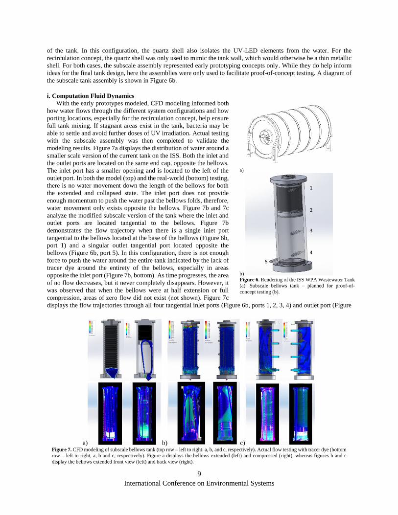
i. Computation Fluid Dynamics
With the early prototypes modeled, CFD modeling informed both
how water flows through the different system configurations and how
porting locations, especially for the recirculation concept, help ensure
full tank mixing. If stagnant areas exist in the tank, bacteria may be
able to settle and avoid further doses of UV irradiation. Actual testing
with the subscale assembly was then completed to validate the
modeling results. Figure 7a displays the distribution of water around a
smaller scale version of the current tank on the ISS. Both the inlet and
the outlet ports are located on the same end cap, opposite the bellows.
The inlet port has a smaller opening and is located to the left of the
outlet port. In both the model (top) and the real-world (bottom) testing,
there is no water movement down the length of the bellows for both
the extended and collapsed state. The inlet port does not provide
enough momentum to push the water past the bellows folds, therefore,
water movement only exists opposite the bellows. Figure 7b and 7c
analyze the modified subscale version of the tank where the inlet and
outlet ports are located tangential to the bellows. Figure 7b
demonstrates the flow trajectory when there is a single inlet port
tangential to the bellows located at the base of the bellows (Figure 6b,
port 1) and a singular outlet tangential port located opposite the
bellows (Figure 6b, port 5). In this configuration, there is not enough
force to push the water around the entire tank indicated by the lack of
tracer dye around the entirety of the bellows, especially in areas
opposite the inlet port (Figure 7b, bottom). As time progresses, the area
of no flow decreases, but it never completely disappears. However, it
was observed that when the bellows were at half extension or full
compression, areas of zero flow did not exist (not shown). Figure 7c
displays the flow trajectories through all four tangential inlet ports (Figure 6b, ports 1, 2, 3, 4) and outlet port (Figure
a)
b)
Figure 6. Rendering of the ISS WPA Wastewater Tank
(a). Subscale bellows tank – planned for proof-of-
concept testing (b).
2
3
4
1
5
a) b) c) Figure 7. CFD modeling of subscale bellows tank (top row – left to right: a, b, and c, respectively). Actual flow testing with tracer dye (bottom
row – left to right, a, b and c, respectively). Figure a displays the bellows extended (left) and compressed (right), whereas figures b and c
display the bellows extended front view (left) and back view (right).

International Conference on Environmental Systems
10
6b, port 5) when the bellows are at 100% extension. The flow was equally split prior to the pump head. In the real-
world application, increasing the number of tangential ports does provide flow around the bellows and mitigates the
existence of no flow regions in the tank design.
Figure 8 reveals the flow pattern when the flow is split using a manifold after passing through the pump head.
Because water follows the path of least resistance, when the bellows are completely compressed, there is little to no
water movement through the inlet port adjacent to the bellows. Needle valves or proportional control valves could be
incorporated into this setup to induce restrictions and force equal distribution of the water through the inlet ports.
ii. COMSOL Modeling
Modeling using the Rap Optics module from COMSOL Multiphysics® allowed AquiSense (Kentucky) to develop
a UV-C LED array to fit around a bellows tank. Two different test cases were assessed during the optical modeling
phase: metal bellows fully extended, and metal bellows fully compressed. For both the ISS wastewater tank and small-
scale test tank, the distance the light has to penetrate to reach the inner diameter of the metal bellows is ~2 cm. The
modeling software assumed a wastewater transmissivity of 90%. Within these assessments, design parameters,
including circumferential spacing, axial spacing and radial offset of the LEDs were varied to determine the most
efficient spacing of the LEDs. Detailed results of the optical modeling will not be discussed in this paper. Bacterial
contamination risks arise in areas of underexposure.
Therefore, when designing the array, uniformity of
radiation was prioritized over the intensity of the irradiation.
Due to the irregular shape of the metal bellows, more LEDs
are needed to irradiate the shadowed regions within the
bellows folds in the compressed state than the extended
state. The irradiance distribution across mesh elements was
analyzed to identify the 0.1th percentile of irradiation. This
irradiance value serves as a lower bound to calculate
estimates on the minimum exposure time to achieve
effective inactivation. The majority of the regions in the
tank will receive values of irradiation far greater than what
is required to suppress a biofilm. As a result of the
modeling, AquiSense developed the UVinaire™(Figure 9).
The main components consist of the array, light shield, and
control unit. The unit will be used with the subscale tank for
the proof-of-concept for the LEDs within wall testing.
D. Current Testing and Future Plans Throughout testing for both sub-scale concepts, the bellows will be fully extended to maximize the surface area the
bacteria can adhere to. At the end of testing, the tanks will be disassembled so the metal bellows can be aseptically
removed and sampled for biofilm growth. Ideally, the UV reactor incorporated will kill most, if not all, bacteria and
prevent biofilm growth throughout the system. Bacterial counts will be determined from samples taken before and
a) b)
Figure 8. CFD modeling of subscale bellows flow pattern when the flow is split prior to (a) and after (b) the pump head.
Figure 9. The AquiSense UVinaire™ will be used to irradiate
bacteria within the bellows tank.
International Conference on Environmental Systems
11
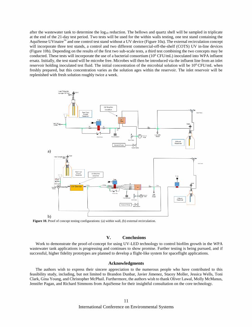
after the wastewater tank to determine the log10 reduction. The bellows and quartz shell will be sampled in triplicate
at the end of the 21-day test period. Two tests will be used for the within walls testing, one test stand containing the
AquiSense UVinaire™ and one control test stand without a UV device (Figure 10a). The external recirculation concept
will incorporate three test stands, a control and two different commercial-off-the-shelf (COTS) UV in-line devices
(Figure 10b). Depending on the results of the first two sub-scale tests, a third test combining the two concepts may be
conducted. These tests will incorporate the use of a bacterial consortium (106 CFU/mL) inoculated into WPA influent
ersatz. Initially, the test stand will be microbe free. Microbes will then be introduced via the influent line from an inlet
reservoir holding inoculated test fluid. The initial concentration of the microbial solution will be 106 CFU/mL when
freshly prepared, but this concentration varies as the solution ages within the reservoir. The inlet reservoir will be
replenished with fresh solution roughly twice a week.
V. Conclusions
Work to demonstrate the proof-of-concept for using UV-LED technology to control biofilm growth in the WPA
wastewater tank applications is progressing and continues to show promise. Further testing is being pursued, and if
successful, higher fidelity prototypes are planned to develop a flight-like system for spaceflight applications.
Acknowledgments
The authors wish to express their sincere appreciation to the numerous people who have contributed to this
feasibility study, including, but not limited to Brandon Dunbar, Javier Jimenez, Stacey Moller, Jessica Wells, Toni
Clark, Gina Young, and Christopher McPhail. Furthermore, the authors wish to thank Oliver Lawal, Molly McManus,
Jennifer Pagan, and Richard Simmons from AquiSense for their insightful consultation on the core technology.
a)
b) Figure 10. Proof of concept testing configurations: (a) within wall, (b) external recirculation.

International Conference on Environmental Systems
12
References
1Almengor, A., Gilbert, S. N., Todd. K., Adam, N., Callahan, M., Ott, C. M., Hanford, A., “Feasibility of
Ultraviolet Technology to Disinfect Spacecraft Water Systems,” International Conference on Environmental
Systems [online server], URL: https://ttu-ir.tdl.org/bitstream/handle/2346/84873/ICES-2019-
118.pdf?sequence=1&isAllowed=y 2Bazley, J. A., Schmidt, P. B., Angeley, J. D., (2009, November). WPA Process Pump Overspeed Anomaly
Report 4297. Unpublished internal document, NASA. 3Tobias, B., Melody, R., Angeley, J. D., (2009, November). WPA MLS Purge and Extension of Process Runs
Anomaly Report 4361. Unpublished internal document, NASA. 4Hegedus, J. S., Davis, M. J., Angeley, J. D., Bahadorani, D., (2009, November). WPA MLS Lo/Lo Liquid Level
Fault Anomaly Report 4367. Unpublished internal document, NASA. 5Byrne, C., (2009, October). WPA Process Pump Overspeed and Low MLS Inlet Pressure PART Record 7393.
Unpublished internal document, NASA. 6Bazley, J., (2014, February). International Space Station Environmental and Thermal Operating Systems
Console Handbook, Volume 25. Unpublished internal document, NASA. 7Verostko, C., Carrier, C., “Ersatz Wastewater Formulations for Testing Water Recovery Systems,”
International Conference on Environmental Systems [online server], https://www.sae.org/publications/technical-
papers/content/2004-01-2448/ 8Simons, R., Pagan, J., Lawal, O., “Low-maintenance, consumables-free disinfection by UV-C LEDs,”
International Conference on Environmental Systems [online server], URL: https://ttu-
ir.tdl.org/bitstream/handle/2346/74131/ICES_2018_153.pdf?sequence=1&isAllowed=y