
uPD70F36x FLASH Programmer - etlweb.com · ©ETL & EWL (2016) UPD70F36x FLASH Programmer User Guide...
19
Engineering Technical Laboratory Rev. 1 *This product is designed and manufactured by Embedded Wireless Laboratory Inc. for ETL. UPD70F36x FLASH Programmer User Guide © ETL & EWL 2016 Microcontroller Development Tool
Transcript of uPD70F36x FLASH Programmer - etlweb.com · ©ETL & EWL (2016) UPD70F36x FLASH Programmer User Guide...

Engineering Technical Laboratory Rev. 1
*This product is designed and manufactured by Embedded Wireless Laboratory Inc. for ETL.
UPD70F36x FLASH Programmer
User Guide
© ETL & EWL 2016 Microcontroller Development Tool

©ETL & EWL (2016) UPD70F36x FLASH Programmer User Guide 2
TABLE OF CONTENTS
1. PREFACE ....................................................................................................................................... 3
2. CHECKLIST AND REQUIREMENTS ......................................................................................... 3
3. INSTALLATION AND USE ......................................................................................................... 4
3.1 USB DRIVERS INSTALLATION FOR WINDOWS 7 .......................................................... 5
3.2 USB DRIVERS INSTALLATION FOR WINDOWS XP ....................................................... 9
3.3 USB DRIVERS UNINSTALLATION ................................................................................... 13
4. SOFTWARE ACTIVATION ....................................................................................................... 14
5. FILES DOWNLOAD ................................................................................................................... 16
6. PROGRAMMING EXAMPLE IN ‘SIMPLE’ MODE ................................................................ 17
7. READING EXAMPLE IN ‘EXPERT’ MODE ............................................................................ 18
8. WARRANTY STATEMENT ....................................................................................................... 19

©ETL & EWL (2016) UPD70F36x FLASH Programmer User Guide 3
1. PREFACE
This manual will guide you through the installation and operation of the UPD70F36x
FLASH Programmer, referenced hereafter as the UPD70F36x-Programmer. The UPD70F36x-Programmer is designed for programming the DFLASH/PFLASH
memory in the Renesas V850 Microcontroller Unit (MCU): uPD70F3629 uPD70F3376
Note: The In-circuit mode only available for the programming devices.
Note: Devices that are not mentioned in above may not be programmable by UPD70F36x-Programmer.
2. CHECKLIST AND REQUIREMENTS
The following describes what items are supplied with the UPD70F36x-Programmer and the system requirements if used by a PC. One ETL Hyper Programmer Board – provided One 9 Pin Flat Cable – provided One USB cable - provided UPD70F36x-Programmer PC software on CD-ROM – Extra Option
Desktop/Laptop PC with USB Port Windows XP (SP3) or Windows 7/8/10 64/32-bit Microsoft.NET Framework Ver. 3.5 SP1 or later version. Power supply: +12V to supply airbag module.
Note: The link can download Microsoft.NET Framework: http://www.microsoft.com/downloads/thankyou.aspx?familyId=ab99342f-5d1a-413d-8319-81da479ab0d7&displayLang=en
©ETL & EWL (2016) UPD70F36x FLASH Programmer User Guide 4
3. INSTALLATION AND USE
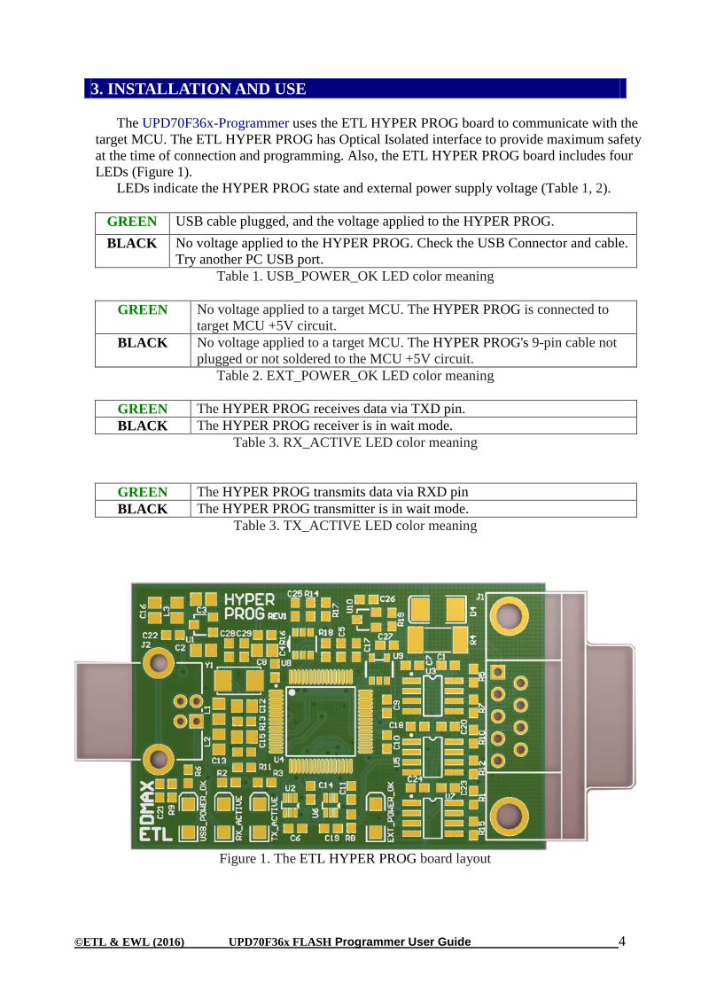
The UPD70F36x-Programmer uses the ETL HYPER PROG board to communicate with the
target MCU. The ETL HYPER PROG has Optical Isolated interface to provide maximum safety at the time of connection and programming. Also, the ETL HYPER PROG board includes four LEDs (Figure 1).
LEDs indicate the HYPER PROG state and external power supply voltage (Table 1, 2).
GREEN USB cable plugged, and the voltage applied to the HYPER PROG. BLACK No voltage applied to the HYPER PROG. Check the USB Connector and cable.
Try another PC USB port. Table 1. USB_POWER_OK LED color meaning
GREEN No voltage applied to a target MCU. The HYPER PROG is connected to
target MCU +5V circuit. BLACK No voltage applied to a target MCU. The HYPER PROG's 9-pin cable not
plugged or not soldered to the MCU +5V circuit. Table 2. EXT_POWER_OK LED color meaning
GREEN The HYPER PROG receives data via TXD pin. BLACK The HYPER PROG receiver is in wait mode.
Table 3. RX_ACTIVE LED color meaning
GREEN The HYPER PROG transmits data via RXD pin BLACK The HYPER PROG transmitter is in wait mode.
Table 3. TX_ACTIVE LED color meaning
Figure 1. The ETL HYPER PROG board layout

©ETL & EWL (2016) UPD70F36x FLASH Programmer User Guide 5
3.1 USB DRIVERS INSTALLATION FOR WINDOWS 7
This section describes how to install the USB drivers for the UPD70F36x-Programmer on the
Windows 7 OS. The ETL HYPER PROG uses the driver supplied by “FTDI Chip” company. The Product ID (PID) was changed to meet the design requirements.
Please follow next steps to install the driver: Download the UPD70F36x-Programmer software form the ETL website. Install the software. After installation, the driver will be located in the "C:\Program
Files\ETL\UPD70F36x_Programmer\USB_Driver\" directory. Plug the HYPER PROG board into a USB port. Wait until the Windows7 failed to install the driver(Figure 2)
Figure 2. The "Windows 7" driver installation failed
Open the "Device Manager" and locate "ETL Hyper Programmer" devices (Figure 3).
Figure 3. The "ETL Hyper Programmer" devices in the "Device Manager."
Right Click on the first "ETL Hyper Programmer" device and then select "Update
Driver Software" menu item.(Figure 4).
Figure 4. The "Update Driver Software" menu item selection
©ETL & EWL (2016) UPD70F36x FLASH Programmer User Guide 6
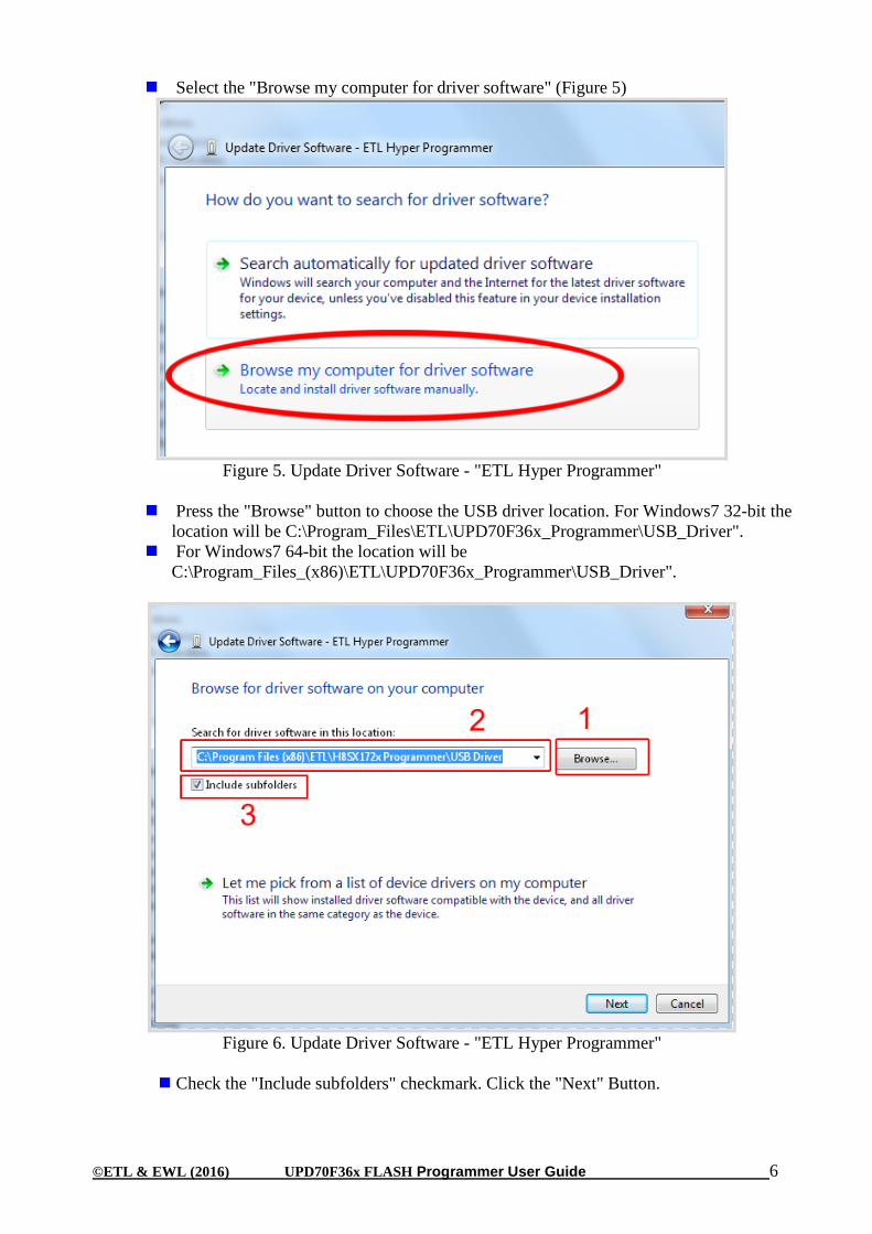
Select the "Browse my computer for driver software" (Figure 5)
Figure 5. Update Driver Software - "ETL Hyper Programmer"
Press the "Browse" button to choose the USB driver location. For Windows7 32-bit the
location will be C:\Program_Files\ETL\UPD70F36x_Programmer\USB_Driver". For Windows7 64-bit the location will be
C:\Program_Files_(x86)\ETL\UPD70F36x_Programmer\USB_Driver".
Figure 6. Update Driver Software - "ETL Hyper Programmer"
Check the "Include subfolders" checkmark. Click the "Next" Button.
©ETL & EWL (2016) UPD70F36x FLASH Programmer User Guide 7
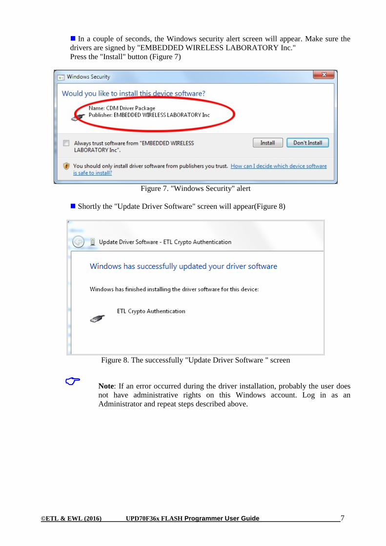
In a couple of seconds, the Windows security alert screen will appear. Make sure the drivers are signed by "EMBEDDED WIRELESS LABORATORY Inc." Press the "Install" button (Figure 7)
Figure 7. "Windows Security" alert
Shortly the "Update Driver Software" screen will appear(Figure 8)
Figure 8. The successfully "Update Driver Software " screen
Note: If an error occurred during the driver installation, probably the user does not have administrative rights on this Windows account. Log in as an Administrator and repeat steps described above.
©ETL & EWL (2016) UPD70F36x FLASH Programmer User Guide 8
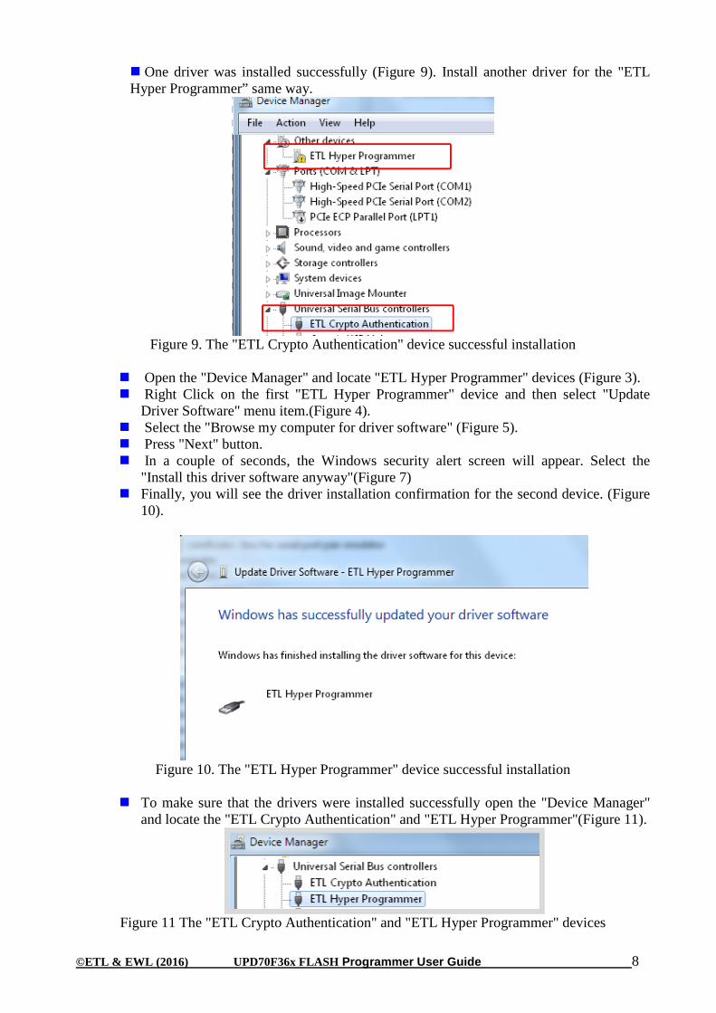
One driver was installed successfully (Figure 9). Install another driver for the "ETL Hyper Programmer” same way.
Figure 9. The "ETL Crypto Authentication" device successful installation
Open the "Device Manager" and locate "ETL Hyper Programmer" devices (Figure 3). Right Click on the first "ETL Hyper Programmer" device and then select "Update
Driver Software" menu item.(Figure 4). Select the "Browse my computer for driver software" (Figure 5). Press "Next" button. In a couple of seconds, the Windows security alert screen will appear. Select the
"Install this driver software anyway"(Figure 7) Finally, you will see the driver installation confirmation for the second device. (Figure
10).
Figure 10. The "ETL Hyper Programmer" device successful installation
To make sure that the drivers were installed successfully open the "Device Manager"
and locate the "ETL Crypto Authentication" and "ETL Hyper Programmer"(Figure 11).
Figure 11 The "ETL Crypto Authentication" and "ETL Hyper Programmer" devices

©ETL & EWL (2016) UPD70F36x FLASH Programmer User Guide 9
3.2 USB DRIVERS INSTALLATION FOR WINDOWS XP This section describes how to install the USB drivers for the UPD70F36x-Programmer on the
Windows XP OS. The ETL HYPER PROG uses the driver supplied by “FTDI Chip” company. The Product ID (PID) was changed to meet the design requirements.
Please follow next steps to install the driver:
Download the UPD70F36x-Programmer software form the ETL website. Install the software. After installation, the driver will be located in the "C:\Program
Files\ETL\UPD70F36x_Programmer\USB_Driver\" directory. Plug the HYPER PROG board into a USB port. Wait for the "Welcome to the Found New Hardware Wizard" screen(Figure 12).
Figure 12 The "ETL Crypto Authentication" and "ETL Hyper Programmer" devices
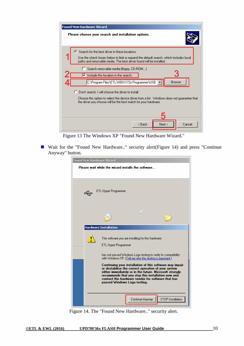
Select the "Install from a list…" button. Press the "Next" button to continue. In next screen select the "Search for best driver in the locations"(Figure 13). Check "Include this location in the search:" checkbox. Browse for the drivers folder location. The location is
"C:\Program_Files\ETL\UPD70F36x_Programmer\USB_Driver" Press "Next" Button.
©ETL & EWL (2016) UPD70F36x FLASH Programmer User Guide 10
Figure 13 The Windows XP "Found New Hardware Wizard."
Wait for the "Found New Hardware.." security alert(Figure 14) and press "Continue
Anyway" button.
Figure 14. The "Found New Hardware.." security alert.
©ETL & EWL (2016) UPD70F36x FLASH Programmer User Guide 11
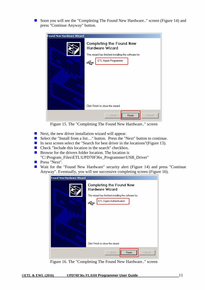
Soon you will see the "Completing The Found New Hardware.." screen (Figure 14) and press "Continue Anyway" button.
Figure 15. The "Completing The Found New Hardware.." screen
Next, the new driver installation wizard will appear. Select the "Install from a list…" button. Press the "Next" button to continue. In next screen select the "Search for best driver in the locations"(Figure 13). Check "Include this location in the search" checkbox. Browse for the drivers folder location. The location is
"C:\Program_Files\ETL\UPD70F36x_Programmer\USB_Driver" Press "Next". Wait for the "Found New Hardware" security alert (Figure 14) and press "Continue
Anyway". Eventually, you will see successive completing screen (Figure 16).
Figure 16. The "Completing The Found New Hardware.." screen

©ETL & EWL (2016) UPD70F36x FLASH Programmer User Guide 12
To make sure that the drivers were installed successfully open the "Device Manager" and locate the "ETL Crypto Authentication" and "ETL Hyper Programmer"(Figure 17).
Figure 17 The "ETL Crypto Authentication" and "ETL Hyper Programmer" devices
Note: If you are logged in as an Administrator and there is still an error at the moment of the driver installation, delete all device entries with the "CDMuninstaller" software. Please refer to Section 3.3 for more information.
Note: Proper UPD70F36x-Programmer and drivers operation can be guaranteed on the Windows XP Service Pack 3 only.

©ETL & EWL (2016) UPD70F36x FLASH Programmer User Guide 13
3.3 USB DRIVERS UNINSTALLATION This section describes how to uninstall the USB drivers for the UPD70F36x-Programmer.
Also, the driver un-installation will be helpful if "Windows" installed the wrong or old driver automatically. The ETL HYPER PROG uses the driver supplied by “FTDI Chip” company. The Product ID (PID) was changed to meet the design requirements. The Product PID of the HYPER PROG is 6692. The Vendor ID (VID) remained the same 0403. To uninstall the driver, we will use the CDMUninstaller software provided by “FTDI Chip” company. Download software at the http://www.ftdichip.com/Support/Utilities.htm website.
Please follow the next steps to uninstall the driver: Unplug the HYPER PROG board from the USB port. Run the "CDMuninstallerGUI.exe" file. Change the PID to 6692(Figure 18). Click the "Add" button. Click the "Remove Devices" Button.
Figure 18 The Drivers are uninstalled by the CDM Uninstaller software
If there were installed drivers in the system, you will see the confirmation of un-
installation.

©ETL & EWL (2016) UPD70F36x FLASH Programmer User Guide 14
4. SOFTWARE ACTIVATION
This section describes the software activation procedure. For activation, the user will
need the "License key" provided in the time of UPD70F36x-Programmer purchase. Also, the "ETL HYPER PROG" board has to be connected to the USB port and drivers previously installed. Refer to the Section 3. Note that the software can be activated on five computers only. If you are going to activate the UPD70F36x-Programmer software on more computers, please contact the ETL technical support. Activation is valid for 14 days. After that period, the user has to activate the software again. The activation procedure is done automatically via the Internet. Make sure there is internet connection before activation procedure. Follow next steps to complete the registration process: Connect the ETL HYPER PROG board to the computer. Execute the UPD70F36x-Programmer software. Press the "Connect Programmer" button. Wait until the "ETL Programmer is connected!" and the HYPER PROG serial number
messages appear.
Figure 19 UPD70F36x-Programmer software
Select the "License" menu item and then press "Register Product". Press the "Read" button to read the HYPER PROG board serial number.(Figure 20). Compare this serial number with the serial number provided together with the license
key. Enter License Key. Press the "Activate" button. After Activation process completed, the "Registration Status" must be "REGISTERED"
and "Clock Manipulation" is "NOT DETECTED".

©ETL & EWL (2016) UPD70F36x FLASH Programmer User Guide 15
Note: If activation procedure failed, please contact ETL technical support at the Email: [email protected]
Figure 20 UPD70F36x-Programmer software activation
Figure 21 Successful UPD70F36x-Programmer software activation
©ETL & EWL (2016) UPD70F36x FLASH Programmer User Guide 16
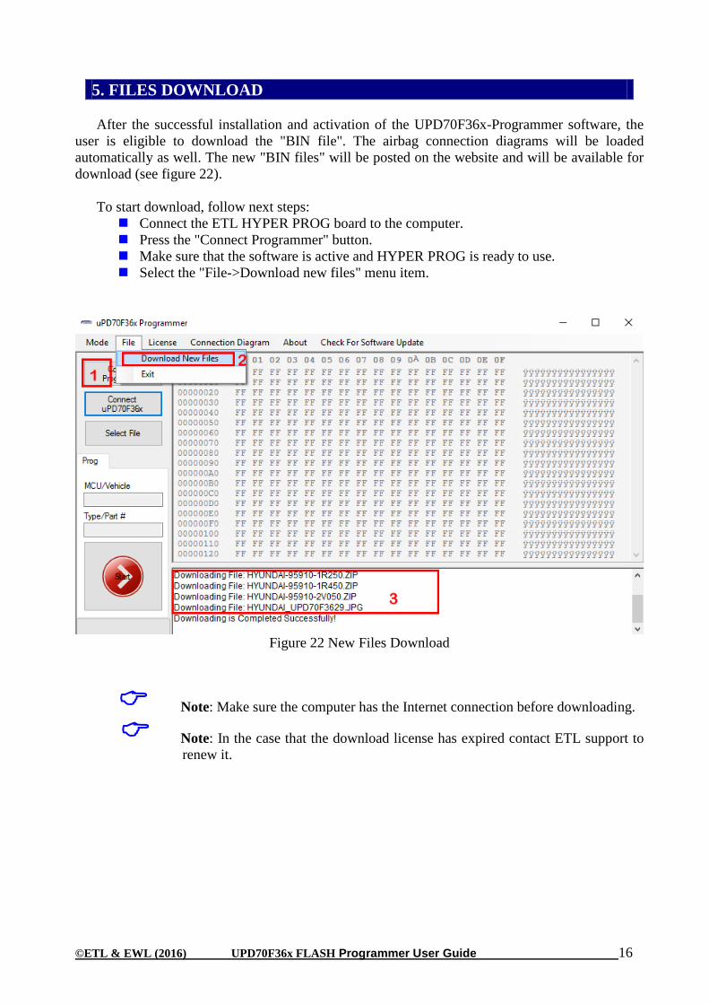
5. FILES DOWNLOAD
After the successful installation and activation of the UPD70F36x-Programmer software, the
user is eligible to download the "BIN file". The airbag connection diagrams will be loaded automatically as well. The new "BIN files" will be posted on the website and will be available for download (see figure 22).
To start download, follow next steps: Connect the ETL HYPER PROG board to the computer. Press the "Connect Programmer" button. Make sure that the software is active and HYPER PROG is ready to use. Select the "File->Download new files" menu item.
Figure 22 New Files Download
Note: Make sure the computer has the Internet connection before downloading.
Note: In the case that the download license has expired contact ETL support to renew it.

©ETL & EWL (2016) UPD70F36x FLASH Programmer User Guide 17
Solder the UPD70F36x-Programmer 9 pin Connector to a target board (airbag). Plug the 9-pin connector to the ETL HYPER PROG board. Press "Connect Programmer" button on UPD70F36x-Programmer software (Figure 23) Press "Connect UPD70F36x" button. Select File with the "Select File" button. Press "Start” Button. Wait until programming procedure finishes with the message: "Programming is
Completed Successfully. Disconnect power from the target board.
Figure 23 UPD70F36x-Programmer programming sequence.
6. PROGRAMMING EXAMPLE IN ‘SIMPLE’ MODE

©ETL & EWL (2016) UPD70F36x FLASH Programmer User Guide 18
Solder the UPD70F36x-Programmer 9 pin Connector to a target board (airbag). Plug the 9 pin connector to the ETL HYPER PROG board. Press "Connect Programmer" button on UPD70F36x-Programmer software (Figure 23) Press "Connect UPD70F36x" button. Select FLASH area(s) by "Select FLASH" button. Press "Start Button". Wait until reading procedure finishes with the message: "Reading is Completed
Successfully!"
Figure 24 UPD70F36x-Programmer reading sequence.
7. READING EXAMPLE IN ‘EXPERT’ MODE
©ETL & EWL (2016) UPD70F36x FLASH Programmer User Guide 19
8. WARRANTY STATEMENT ETL guarantees all delivered products for 60 days from registration date against manufactory
defects.


