Project Proposal RJM Nuijten BSc, student number 3350290 1 ...

This is an electronic reprint of the original article.This reprint may differ from the original in pagination and typographic detail.
Powered by TCPDF (www.tcpdf.org)
This material is protected by copyright and other intellectual property rights, and duplication or sale of all or part of any of the repository collections is not permitted, except that material may be duplicated by you for your research use or educational purposes in electronic or print form. You must obtain permission for any other use. Electronic or print copies may not be offered, whether for sale or otherwise to anyone who is not an authorised user.
Uotinen, Lauri; Nuijten, Guido; Martinelli, Daniele; Lehmusjärvi, Riitta; Rinne, MikaelRock engineering design process in ONKALO rock characterisation facility
Published in:Rock Engineering and Technology for Sustainable Underground Construction EUROCK 2012, Stockholm 28-30.5.2012
Published: 30/05/2012
Document VersionPeer reviewed version
Please cite the original version:Uotinen, L., Nuijten, G., Martinelli, D., Lehmusjärvi, R., & Rinne, M. (2012). Rock engineering design process inONKALO rock characterisation facility. In Rock Engineering and Technology for Sustainable UndergroundConstruction EUROCK 2012, Stockholm 28-30.5.2012 BeFo - Rock Engineering Research Foundation &Swedish National Group of ISRM.
Eurock 2012 Page 1
Rock engineering design process in ONKALO rock characterisation facility
L.K.T. Uotinen, Kalliosuunnittelu Oy Rockplan Ltd., Aalto University, School of Engineering, Finland G.A. Nuijten & D. Martinelli, Kalliosuunnittelu Oy Rockplan Ltd., Finland R. Lehmusjärvi, Posiva Oy, Finland M. Rinne, Aalto University, School of Engineering, Finland
Abstract: The ONKALO rock characterisation facility is located in the Olkiluoto area in the west coast of Finland. It aids in collecting the further data needed for the appli-cation of the construction license for the repository of spent nuclear fuel that will be submitted in 2012. It provides an opportunity to develop excavation techniques and final disposal techniques in realistic in situ conditions. The goal of the facility is to provide information for the design of the planned nuclear repository. The ONKALO design method can be considered as a prediction and observation method. Typical rock conditions can be handled using the Observational Method (Peck 1969) ap-proach, and more complex cases (e.g. stress-induced damage, extensively cracked areas, crossings, heat-affected zones, etc.) are handled with numerical and analytical predictions. The design method can be divided into five phases: description of infor-mation on existing geology, site investigation and interpretation, obtaining rock mass parameters, calculations, and design. The method has undergone continuous im-provement during the different excavation stages and as new rock mechanical chal-lenges have been detected. Examples of Eurocode compatible rock reinforcement de-sign are shown. Finally, the suitability of the current design method for the design of the spent nuclear fuel repository is discussed. Theme: Design Methods Keywords: ONKALO, repository, Observational Method, reinforcement, Eurocode
Eurock 2012 Page 2
1 INTRODUCTION
Rock engineering design is a challenging and multi-disciplinary task, which ranges from optimisation of the layout, excavation direction and tunnel shape and design of water proofing and grouting to design of rock reinforcement. In typical urban rock engineering, the main problems lie in water proofing and cost-minimisation while maintaining a sufficient level of quality. In ONKALO, the main issue is to meet the high safety and technical requirements while maintaining an acceptable excavation speed and cost. Additional problems arise from imposed material restrictions and from exceptional environmental conditions (e.g. stress-induced damage, thermal loading, high salinity, and long serviceability life) of ONKALO.
ONKALO aids in collecting the further data needed for the application of the con-struction licence that will be submitted in 2012. ONKALO also provides an opportuni-ty to develop excavation techniques and final disposal techniques in realistic condi-tions (Posiva 2011a). The goal is to provide information about the planned nuclear repository area. This acquired knowledge consists mainly of geological information, such as rock types and their quality as well as the presence of weakness zones and that of water. The parameters obtained influence the design of the underground facility, and the excavation allows of continuous improvement of the process.
The Eurocodes are a set of European design principles, rules, and guidance in-tended for the design of load-carrying structures. The codes have been compiled by the CEN Technical Committee 250. The intent of the Eurocodes is to unify the design methodology. In Finland (and in Sweden and Norway), there is no formal procedure on how to design rock spaces. The design is based on a designer’s expertise, experi-ence, views, and specific procedures. The Eurocodes do not explicitly state how to design rock spaces, but they define the minimum requirements on how to design struc-tures. For a more throughout introduction of the use of the Eurocodes in hard rock engineering, please refer to Uotinen et al. 2011.
The Eurocode 7 (Geotechnical design) allows the Observational Method (OM) to be used as a part of the design process, given that certain criteria are met (see next chapter). The OM requires determining actions beforehand and then choosing the cor-responding action based on in situ measurements. It was formulated by Terzaghi and published by Peck in 1969. In his paper, Peck states that the most serious blunder is the failure to select appropriate courses for all foreseeable deviations of conditions.
The rock engineering design used in the previously completed contracts (TU1 through TU5) has been documented by Syrjänen et al. (2006, 2007, 2008), Tikkanen et al. (2009), and Nuijten et al. (2010a, 2010b). In 2009, a description of rock rein-forcement design methods in use in ONKALO at that time was made (Uotinen et al. 2009), audited, revised, and finally approved for use in the TU4 and TU5 contracts. These documents are available (mostly in Finnish) from the document bank used by Posiva for authorised users. There is no previously published material on the rock engineering design process in ONKALO. However, all the initial data and supplemen-tary work have been published in the Olkiluoto Site Descriptions (Posiva 2004, 2006, 2008, 2011b).
In this paper, we describe the current rock engineering design process in ON-KALO. The method has undergone continuous improvement as new rock engineering challenges have been met. Examples of rock engineering design are shown. The au-thors’ opinion on applying the method to the design of the repository is presented.
The paper is divided into four chapters. The upcoming chapter two describes the methods and materials used. The chapter three describes results, which in this context are improvements of the design process. Finally, chapter four discusses the usability of the design process for the design of the spent nuclear fuel repository.
Eurock 2012 Page 3
2 METHODS AND MATERIALS
2.1 Observational Method (OM)
Until the mid-20th century, rock engineering was carried out either by adopting an excessive factor of safety or by making generalised assumptions. Terzaghi noted this and applied what he referred to as the “third method” from soil mechanics. Later Peck published this method (1969) in a slightly modified form. The following quote is a brief summary of the method by Peck: (a) Exploration sufficient to establish at least the general nature, pattern, and proper-ties of the deposits, but not necessary in detail. (b) Assessment of the most probable conditions and the most unfavourable conceiva-ble deviations from these conditions. In this assessment geology often plays a major role. (c) Establishment of the design based on a working hypothesis of behaviour anticipat-ed under the most probable conditions. (d) Selection of quantities to be observed as construction proceeds and calculation of their anticipated values on the basis of the working hypothesis. (e) Calculation of values of the same quantities under the most unfavourable condi-tions comparable with the available data concerning the subsurface conditions. (f) Selection in advance of a course of action or modification of design for every fore-seeable significant deviation of the observational findings from those predicted on the basis of the working hypothesis. (g) Measurement of quantities to be observed and calculation of actual conditions. (h) Modification of design to suit actual conditions. (Peck 1969) EN 1997-1 (the Eurocode 7: Geotechnical design - Part 1: General rules) states the design requirements, which are also followed in the ONKALO work. Explicitly, the EC7 mentions the Observational Method as a tool to be used as a part of the design process. The limit state based design is required for each geotechnical design situation, and the OM is one of the four allowed approaches. The following quote is from the EC7 concerning the use of the OM: (1) When prediction of geotechnical behaviour is difficult, it can be appropriate to apply the approach known as "the observational method", in which the design is re-viewed during construction. (2)P The following requirements shall be met before construction is started: — acceptable limits of behaviour shall be established; — the range of possible behaviour shall be assessed and it shall be shown that there is an acceptable probability that the actual behaviour will be within the acceptable lim-its; — a plan of monitoring shall be devised, which will reveal whether the actual behav-iour lies within the acceptable limits. The monitoring shall make this clear at a suffi-ciently early stage, and with sufficiently short intervals to allow contingency actions to be undertaken successfully; — the response time of the instruments and the procedures for analysing the results shall be sufficiently rapid in relation to the possible evolution of the system; — a plan of contingency actions shall be devised, which may be adopted if the moni-toring reveals behaviour outside acceptable limits. (3)P During construction, the monitoring shall be carried out as planned.

Eurock 2012 Page 4
(4)P The results of the monitoring shall be assessed at appropriate stages and the planned contingency actions shall be put into operation if the limits of behaviour are exceeded. (5)P Monitoring equipment shall either be replaced or extended if it fails to supply reliable data of appropriate type or in sufficient quantity. (EN 1997-1 s. 2.7) The sections marked with the letter P are principles for which there is no alternative, unless specifically stated. In other words, the sections 2.7(2)P through 2.7(5)P are mandatory in Eurocode based use of the Observational Method.
Posiva has published WR 2002-48 (The Observational Method applied to engi-neering and construction of the access to the ONKALO facility), which describes Posiva’s design strategy to apply the OM to the engineering and construction of the access to the ONKALO facility. The facility is simultaneously considered to be a learning exercise to develop the methodology for the implementation of the repository. The report concludes that the concept of the Observational Method has been misun-derstood in certain instances with the perception that design issues are not sorted out in advance, which can lead to sloppy engineering. However, the proper use of the Ob-servational Method is exactly the opposite.
The most important conclusions of WR 2002-48 are: - the method is applicable to the geotechnical part of the design - decide-as-you-go (not design-as-you-go or learn-as-you-go) - total design should be done before realisation - only a tool to adapt to changing geological conditions. The learning process, including aspects like safety, logistics, traffic, ventilation, elec-tricity, and main layout strategy, are to be finished before realisation – not during real-isation. (Modified from Posiva 2011b.)
2.2 ONKALO Design Method (ODM)
The ONKALO design method can be considered as a prediction and observation (out-come) method. The method repeats cyclically as more information becomes available. The outcome depends on the initial data of the process. The four repeating steps are the core of the method (Fig. 1):
Site description: Olkiluoto Site Descriptions (Posiva 2004, 2006, 2008, and 2011a) collect and present all the material produced during investigations and analy-sis. This step represents the accumulated data from the surrounding rock mass.
Site investigation: Every in situ investigation is processed in order to accumulate information and to document the initial data used in the design. The interpretation process is documented to provide full traceability of the parameters.
Data processing: The data from site investigations is used to compose the initial data for rock engineering purposes. To obtain the best possible result, it is essential to have a strong co-operation especially between the geologist (GEOL) and the rock engineer (KAT).
Calculation: The initial data, functional boundary conditions, and the geometry of the facility are taken into account as the rock engineering calculations are made. The calculation method and the governing regulations (e.g. the Eurocode) that influence the design process are stated. The documents produced in this stage include rein-forcement and grouting calculations.

Eurock 2012 Page 5
Figure 1. Visual description of the phases and the design process
The process repeats as new information becomes available. This is essential for a pre-diction (based on latest data) and observation (using continued monitoring) method. New information becomes available at the following stages:
Deep boreholes: As of 2011, a total of 52 long holes (up to 1 km deep) have been drilled. The drilling investigations can be utilised for establishing the location and properties of particular bedrock structures. In addition to holes drilled from the sur-face, drilling also takes place underground. Long characterisation holes will also be drilled from ONKALO to the location of the repository. (Posiva 2011c) This data is presented in the Rock Mechanics Model (RMM) and in other borehole analyses.
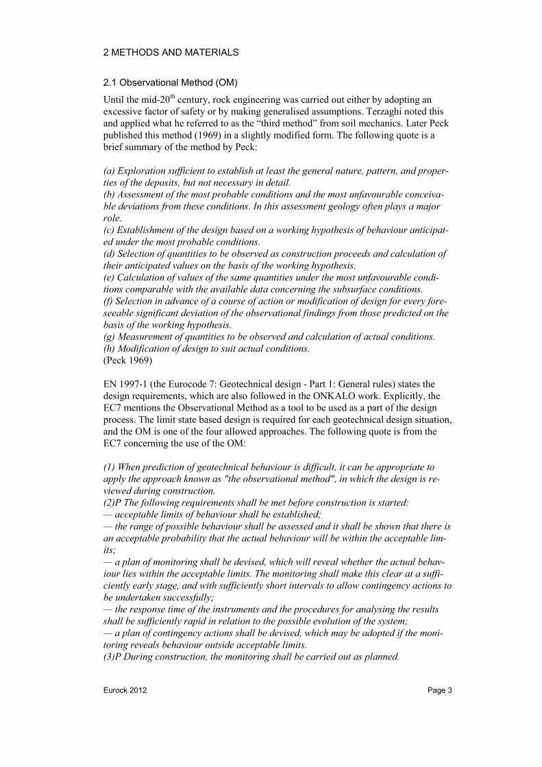
ONKALO experience: The experience accumulated in ONKALO is extensive: many of the straight tunnel sections have pilot hole data, which has been thoroughly analysed by rock engineers and geologists. The designer has implemented the data generated by Posiva. The designer inspects the tunnel on a regular basis, and the most critical observations can lead to corrective measures or additional reinforcement. To predict areas most prone to stress-induced damage, modelling was carried out from the entire technical area (TU5 and TU5A shown in Fig. 2). Wedge analysis has been per-formed in areas where the cracks can interact and create blocks. Additionally, the rock engineering design, based on Q classification, has been carried out for areas TU4, TU5 and TU5A. (Nuijten 2011)
Pilot holes: From the end of the ONKALO tunnel, a number of 50- to 300-metre-long pilot holes will be drilled at pre-determined locations. The purpose of these pilot holes is to verify the rock quality in the location the tunnel is going to be before any excavation takes place, and in particular to locate any water-conducting fracture zones and other rock characteristics that may be significant for the construction. (Posiva 2011d) This method will be used extensively during the excavation of the repository.
Round mapping: A brief inspection of the rock quality is performed immediately after excavation, and if anything out of the ordinary is observed, the designer comes to the site as soon as possible. Otherwise, the site visits follow a predefined schedule. The Q classification has two pitfalls when applied to the ONKALO conditions: the cracking direction in relation to local anisotropy direction and the local stress-driven
Eurock 2012 Page 6
behaviour. Using the geometry, crack information, anisotropy, and stress-driven dam-age analysis, the classification can be adjusted. Systematic mapping produces exten-sive data which is used as the final control for the reinforcement. It also enables the discovery of blocks that may require additional reinforcement. (Hatakka 2011)
Monitoring: The rock reinforcement solutions are optimised to meet the known and predicted conditions at the moment of design. If the design of ONKALO (or the spent fuel repository) is modified, this could cause localised damage in the previously reinforced parts. Additionally, the pre-existing parts have to cope with the altering environmental conditions (e.g. salinity, pH, heat…) as well as the vibration of the blasting work. Vibrations and in situ stress changes caused by excavation can break loose small rock pieces or poorly applied shotcrete that has evaded controlling measures. Continuous monitoring of the previously constructed and reinforced parts is vital in order to prevent accidents. Scaling is to be performed on a regular basis on rock surfaces to safely bring down loosened rock.
3 RESULTS
Three examples are given. The first one is stress-induced damage prediction based on the ONKALO experience (Fig. 2). The second example is the processing of pilot hole data for usage in rock engineering preliminary design (Fig. 3). The last example de-scribes how round mapping can occasionally require a refined design (Fig. 4).
Figure 2. Conservative prediction of stress-induced damage in the technical area (TU5 and TU5A). Damage is marked by green (light grey in print). Damage depth modelled using Midas GTS 3.0.0(4) (modified from Martinelli 2010)
Eurock 2012 Page 7
The first example is stress-induced damage prediction based on published stress data in Posiva 2008 (Fig. 2). The figure shows a part of the technical area of ONKALO. The damage is predicted using the stress-induced damage strength of 57% of uniaxial compressive strength. According to Site Report 2008 (Posiva 2008), the stresses are in the order of σH = 32 MPa, σh = 20 MPa, and σz = 12 MPa (z = 420 m). The conserva-tive results show a worst-case damage depth of 300 mm in the south–north-oriented tunnels and 200 mm in the shaft walls with up to 1,150 mm in the bottom parts of shafts. The expected (mean) results (see Martinelli 2010) show no damage in any of the tunnels and 100 mm in the shaft walls with up to 750 mm in the bottom parts of the shafts. Currently (23rd November, 2011), only the exhaust air shaft (the northern-most shaft in Fig. 2) has been raisebored in the technical area. Some damage has been detected, and analysis is on-going.
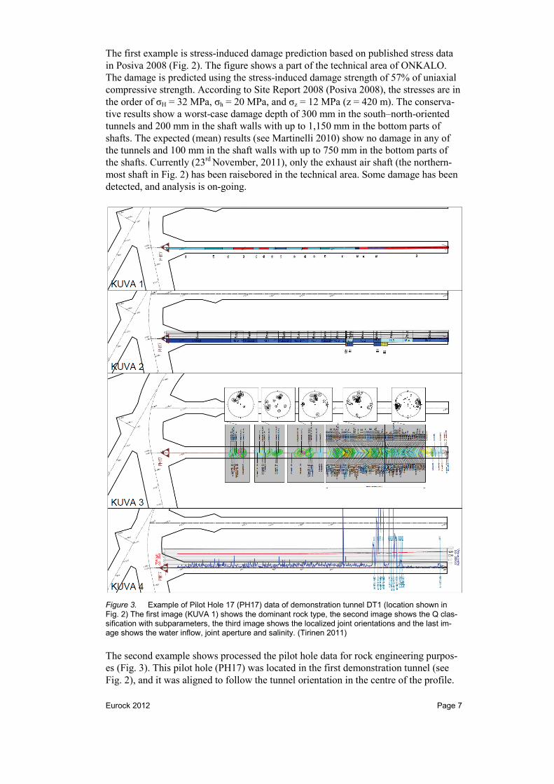
Figure 3. Example of Pilot Hole 17 (PH17) data of demonstration tunnel DT1 (location shown in Fig. 2) The first image (KUVA 1) shows the dominant rock type, the second image shows the Q clas-sification with subparameters, the third image shows the localized joint orientations and the last im-age shows the water inflow, joint aperture and salinity. (Tirinen 2011)
The second example shows processed the pilot hole data for rock engineering purpos-es (Fig. 3). This pilot hole (PH17) was located in the first demonstration tunnel (see Fig. 2), and it was aligned to follow the tunnel orientation in the centre of the profile.
Eurock 2012 Page 8
The data shows a water-bearing weakness zone intersecting with the end of the tunnel. It was later decided that this demonstration tunnel be shortened. The fracture infor-mation (shown in the second and third panels of Fig. 3) was used in wedge analysis to verify that the preliminary design for the tunnel is adequate.
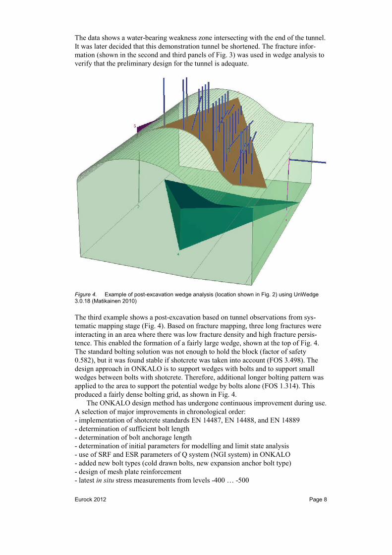
Figure 4. Example of post-excavation wedge analysis (location shown in Fig. 2) using UnWedge 3.0.18 (Matikainen 2010)
The third example shows a post-excavation based on tunnel observations from sys-tematic mapping stage (Fig. 4). Based on fracture mapping, three long fractures were interacting in an area where there was low fracture density and high fracture persis-tence. This enabled the formation of a fairly large wedge, shown at the top of Fig. 4. The standard bolting solution was not enough to hold the block (factor of safety 0.582), but it was found stable if shotcrete was taken into account (FOS 3.498). The design approach in ONKALO is to support wedges with bolts and to support small wedges between bolts with shotcrete. Therefore, additional longer bolting pattern was applied to the area to support the potential wedge by bolts alone (FOS 1.314). This produced a fairly dense bolting grid, as shown in Fig. 4.
The ONKALO design method has undergone continuous improvement during use. A selection of major improvements in chronological order: - implementation of shotcrete standards EN 14487, EN 14488, and EN 14889 - determination of sufficient bolt length - determination of bolt anchorage length - determination of initial parameters for modelling and limit state analysis - use of SRF and ESR parameters of Q system (NGI system) in ONKALO - added new bolt types (cold drawn bolts, new expansion anchor bolt type) - design of mesh plate reinforcement - latest in situ stress measurements from levels -400 … -500

Eurock 2012 Page 9
4 DISCUSSION
The results indicate that the ONKALO design method can also be applied to the de-sign of the spent nuclear fuel repository. However, the learning part is now over, and the design solutions to each foreseeable problem are to be established beforehand. It is expected that something out of the ordinary may occur. In these cases, the solution is to be described as a process (e.g. “Design process in case of unexpected rock condi-tions”), and the design methodology can be described, as has been the case in ON-KALO. However, the end repository is not a practice ground, and continuous im-provement can only be done in a limited scale in predetermined fashion.
It is suggested to describe the most probable rock types (RT) using variable crite-ria and then design the matching excavation shapes, reinforcement types, and grouting fans. For example, good quality mica gneiss rock could be designated as MGN10, where MGN stands for Mica Gneiss and 10 designates the Q classification corre-sponding to good quality. The Rock Types should be chosen so that they cover ap-proximately 90 % of the design cases. Too many reduce the usability of the system and too few cannot take into account the most common deviations. The rest 10 % of the design cases are designed using the limit state calculations (e.g. numerical model-ling, wedge analysis, stochastic analysis, etc.) according to declared methodology.
There are two major changes compared with the design methodology of ON-KALO. The first one is that the durability and coupled physical issues of the rein-forcements were chosen to be studied in detail more carefully and that a temporary service length time of 30 years was chosen for the rock reinforcement. In the design of the repository, easily monitored and maintenance parts may have a lower service life, but all other reinforcement must be designed to last the entire design life time of ON-KALO (120 years). The design life for 120 years and severe conditions have already been carried out in the rock engineering of the ONKALO shafts and shaft rock rein-forcement, since these facilities cannot be upgraded easily later on.
The second major change is the desire to minimise the amount of high pH prod-ucts (e.g. shotcrete, concrete, and grout), which could be harmful for the bentonite buffer. Reduction of shotcrete has been tested in the POSE (Posiva ONKALO Spall-ing Experiment) niche, exploratory niche 5, and in the demonstration tunnels DT1 and DT2. Shotcrete can be replaced by using steel mesh with suitably small grid spacing. Grouted rock bolts can be replaced by ungrouted mechanically anchored bolts (expan-sion anchors) with secondary metal pipe encasing for corrosion protection. Secondary rock anchors (e.g. mesh anchors) can also be replaced by threaded bars with expansion anchors. For secondary rock anchors, the corrosion protection can be achieved by using sacrificial dimensioning or a secondary metal pipe encasing. For all steel com-ponents the primary corrosion protection is the correct choice of steel material type. Slotted wedge anchors (aka. Kiruna bolts) are not recommended, because they can become loose during the planned service life.
On a larger scale, there are many things to be considered in the rock engineering design. One such thing is the safety during construction and operation (e.g. double exit policy). There are significant material flows related to excavation and transportation of dangerous materials (e.g. explosives and fuel). There are multiple moving vehicles during construction and during use and the traffic planning will affect the layout. Ven-tilation and other infrastructure will affect tunnel cross section size and require auxil-iary space. The electricity supply will require auxiliary space and secondary routes and fire protection measures. The excavation equipment requires certain amount of space, loading and turning areas, maintenance area and storage area. Given the desire to minimize space, it should be thought out how to store the canisters, rock, explo-sives, maintenance equipment, work equipment (e.g. bolts, wire mesh, concrete, grout…), fuels and gases and safety containers.
Eurock 2012 Page 10
In all likelihood the ONKALO design method can be applied to the design of the spent nuclear fuel repository. The methodology should now be finalized and modified for use in the repository area. It may also be adapted to be used in other similar high reliability facilities (e.g. other repositories or research laboratories deep underground). For conventional rock engineering projects, the Observational Method as described in the Eurocode is sufficient and the benefit from the added systematisation of the ON-KALO design method may be less than the introduced expense.
5 ACKNOWLEDGEMENTS
The authors acknowledge Topias Siren, Lassi Hatakka and Jesse Ström for active con-tribution in the improvement of the rock engineering design process. The authors thank Pauli Syrjänen and Jukka Pöllä for constructive criticism in order to develop a continuously improving rock engineering design process.
6 REFERENCES
EN 1997-1, 2004, Eurocode 7: Geotechnical design - Part 1: General rules, CEN Hatakka, L. 2011, Round mapping and interpretation for rock reinforcement design,
Posiva Rock Mechanics day 2011, ONK-108249, Posiva (restricted access) Martinelli, D. 2010, TU5 jännitystilavaurioennuste tilat tasolla -415…-438, ONK-
105374, Posiva (restricted access) Matikainen, A. 2010, TU5 paaluvälin 4363-4372 lohkoanalyysi ja lujitusratkaisut,
ONK-106463, Posiva (restricted access) Nuijten G.A. & Tikkanen, R. & Roinisto, J. 2010a TU5 demotunneleiden lou-
hintatyöselostus, ONK-105865, Posiva (restricted access) Nuijten G.A. & Tikkanen, R. & Roinisto, J. 2010b TU5 demotunneleiden louhinnan
menettelyohje, ONK-106459, Posiva (restricted access) Nuijten G.A. 2011, TU5A-louhinta, lujituslaskennat, ONK-108388, Posiva (restricted
access) Peck, R.B. 1969, Advantages and limitations of the observational method in applied
soil mechanics, Géotechnique 19, No. 2, 171–187. Posiva, 2002, The Observational Method applied to engineering and construction of
the access to the ONKALO facility, Working Report 2002-48, Posiva Posiva, 2006. Olkiluoto Site Description 2006. Posiva-report 2007-3, Posiva Posiva, 2008. Olkiluoto Site Description 2008. Posiva-report 2009-1, Posiva Posiva, 2011a. Posiva - ONKALO. Obtained on 11.11.2011:
http://www.posiva.fi/en/research_development/onkalo Posiva, 2011b. Olkiluoto Site Description 2011. Posiva (announced) Posiva, 2011c. Posiva - Drilling. Obtained on 11.11.2011:
http://www.posiva.fi/en/research_development/aboveground_site_investigations/drilling/
Posiva, 2011d. Posiva – Probe and Pilot Holes. Obtained on 11.11.2011: http://www.posiva.fi/en/research_development/onkalo/research_conducted_in_onkalo/probe_and_pilot_holes/
Syrjänen, P. & Mikkola, J. 2006 Louhintatyöselostus TU2, ONK-002759, Posiva (re-stricted access)
Syrjänen, P. & Mikkola, J. & Gulin, K. 2007 Louhintatyöselostus TU3, ONK-004647, Posiva (restricted access)
Syrjänen, P. & Mikkola, J. & Gulin, K. 2008 Louhintatyöselostus TU4, ONK-100734, Posiva (restricted access)
Tikkanen, R. & Nuijten G.A. & Roinisto, J. 2009 TU5 louhintatyöselostus, ONK-103640, Posiva (restricted access)

Eurock 2012 Page 11
Tirinen, J. 2011, Pilottireiän ONK-PH17 tutkimustiedot, ONK-106697, Posiva (re-stricted access)
Uotinen, L.K.T. & Nuijten G.A. & Roinisto, J. 2009 Lujituslaskentamenetelmät, ONK-103286, Posiva (restricted access)
Uotinen, L.K.T. & Nuijten, G.A. & Siren, T. & Ström, J. & Hakala, M. & Rinne, M. 2011, Eurocodes in Hard Rock Engineering in Finland, World Tunnelling Con-gress 2011, Finland


![Martinelli, A [2005, Ch1]Modernization and Modernity](https://static.fdocuments.us/doc/165x107/577cdd951a28ab9e78ad5453/martinelli-a-2005-ch1modernization-and-modernity.jpg)