UNVENTED (VENT-FREE) GAS LOG HEATER · 110398-01A For more information, visit 33 1. This appliance...
28
Also Design-Certified As A Vented Decorative Appliance Patent Pending P I L O T O F F O N LO REMOTE OFF HI FLAME-MAX ® Multi-Sided Log Design VYM27NR/PR FVFM27NR/PR Remote Control Ready Model WARNING: If the information in this manual is not followed exactly, a fire or explosion may result causing property damage, per- sonal injury, or loss of life. — Do not store or use gasoline or other flammable vapors and liquids in the vicinity of this or any other appliance. — WHAT TO DO IF YOU SMELL GAS • Do not try to light any appliance. • Do not touch any electrical switch; do not use any phone in your building. • Immediately call your gas supplier from a neighbor’s phone. Follow the gas supplier’s instructions. • If you cannot reach your gas supplier, call the fire department. — Installation and service must be per- formed by a qualified installer, service agency, or the gas supplier. WARNING: Improper installation, ad- justment, alteration, service, or main- tenance can cause injury or property damage. Refer to this manual for cor- rect installation and operational proce- dures. For assistance or additional in- formation consult a qualified installer, service agency, or the gas supplier. WARNING: This appliance is for installa- tion only in a solid-fuel burning masonry or UL127 factory-built fireplace, or in an approved ventless firebox. It is design certified for these installations in accor- dance with ANSI Z21.11.2. Exception: Do not install this appliance in a factory- built fireplace that includes instructions stating it has not been tested or should not be used with unvented gas logs. WARNING: This is an unvented gas-fired heater. It uses air (oxygen) from the room in which it is installed. Provisions for adequate combustion and ventilation air must be provided. Refer to Air for Combustion and Ventilation section on page 4 of this manual. This appliance may be installed in an aftermarket,* manufactured (mobile) home, where not prohibited by local codes. This appliance is only for use with the type of gas indicated on the rating plate. This appliance is not convertible for use with other gases. * Aftermarket: Completion of sale, not for purpose of resale, from the manufacturer For more information, visit www.desatech.com For more information, visit www.desatech.com UNVENTED (VENT-FREE) GAS LOG HEATER OWNER’S OPERATION AND INSTALLATION MANUAL TM Save this manual for future reference. Save this manual for future reference.
Transcript of UNVENTED (VENT-FREE) GAS LOG HEATER · 110398-01A For more information, visit 33 1. This appliance...

Also Design-Certified As A Vented Decorative Appliance
Patent PendingPILOT
OFF
ON
LO
REMOTE
OFF
HI
FLAME-MAX®
Multi-SidedLog Design
VYM27NR/PRFVFM27NR/PRRemote Control
Ready Model
WARNING: If the information in this manualis not followed exactly, a fire or explosionmay result causing property damage, per-sonal injury, or loss of life.
— Do not store or use gasoline or otherflammable vapors and liquids in thevicinity of this or any other appliance.
— WHAT TO DO IF YOU SMELL GAS• Do not try to light any appliance.• Do not touch any electrical switch; do
not use any phone in your building.• Immediately call your gas supplier from
a neighbor’s phone. Follow the gassupplier’s instructions.
• If you cannot reach your gas supplier,call the fire department.
— Installation and service must be per-formed by a qualified installer, serviceagency, or the gas supplier.
WARNING: Improper installation, ad-justment, alteration, service, or main-tenance can cause injury or propertydamage. Refer to this manual for cor-rect installation and operational proce-dures. For assistance or additional in-formation consult a qualified installer,service agency, or the gas supplier.
WARNING: This appliance is for installa-tion only in a solid-fuel burning masonryor UL127 factory-built fireplace, or in anapproved ventless firebox. It is designcertified for these installations in accor-dance with ANSI Z21.11.2. Exception: Donot install this appliance in a factory-built fireplace that includes instructionsstating it has not been tested or shouldnot be used with unvented gas logs.
WARNING: This is an unvented gas-fired heater. It uses air (oxygen) from the room inwhich it is installed. Provisions for adequate combustion and ventilation air must beprovided. Refer to Air for Combustion and Ventilation section on page 4 of this manual.
This appliance may be installed in an aftermarket,* manufactured (mobile) home, wherenot prohibited by local codes.This appliance is only for use with the type of gas indicated on the rating plate. Thisappliance is not convertible for use with other gases.
* Aftermarket: Completion of sale, not for purpose of resale, from the manufacturer
For more information, visit www.desatech.comFor more information, visit www.desatech.com
UNVENTED (VENT-FREE)GAS LOG HEATEROWNER’S OPERATION ANDINSTALLATION MANUAL
TM
Save this manual for future reference.Save this manual for future reference.

110398-01A
For more information, visit www.desatech.comFor more information, visit www.desatech.com
2
Due to high temperatures, the appliance should belocated out of traffic and away from furniture anddraperies.
Do not place clothing or other flammable material onor near the appliance. Never place any objects on theheater.
Heater base assembly becomes very hot when run-ning heater. Keep children and adults away from hotsurface to avoid burns or clothing ignition. Heaterwill remain hot for a time after shutdown. Allowsurface to cool before touching.
Carefully supervise young children when they are inthe room with heater. When using the hand-heldremote accessory, keep selector switch in the OFFposition to prevent children from turning on burnerswith remote.
You must operate this heater with a fireplace screenin place. Make sure fireplace screen is closed beforerunning heater.
WARNING: Any change to this heater or its con-trols can be dangerous.
WARNING: Do not allow fans to blow directly intothe fireplace. Avoid any drafts that alter burner flamepatterns. Ceiling fans can create drafts that alterburner flame patterns. Altered burner patterns cancause sooting.
WARNING: Do not use a blower insert, heatexchanger insert, or other accessory not approvedfor use with this heater.
SAFETY INFORMATION
IMPORTANT: Read this owner’s manual carefullyand completely before trying to assemble, operate, orservice this fireplace. Improper use of this fireplacecan cause serious injury or death from burns, fire,explosions, electrical shock, and carbon monoxidepoisoning.
WARNINGS
DANGER: Carbon monoxide poisoning may leadto death!
Carbon Monoxide Poisoning: Early signs of carbon monoxidepoisoning resemble the flu, with headaches, dizziness, or nausea. Ifyou have these signs, the fireplace may not have been installedproperly. Get fresh air at once! Have fireplace inspected andserviced by a qualified service person. Some people are moreaffected by carbon monoxide than others. These include pregnantwomen, people with heart or lung disease or anemia, those under theinfluence of alcohol, and those at high altitudes.
Propane/LP gas and natural gas are both odorless. An odor-makingagent is added to each of these gases. The odor helps you detect a gasleak. However, the odor added to these gases can fade. Gas may bepresent even though no odor exists.
Make certain you read and understand all warnings. Keep thismanual for reference. It is your guide to safe and proper operationof this heater.
TABLE OF CONTENTSSAFETY INFORMATION
TABLE OF CONTENTS
SAFETY INFORMATION ............................................................ 2
PRODUCT IDENTIFICATION ..................................................... 3
LOCAL CODES ........................................................................... 4
UNPACKING ............................................................................... 4
PRODUCT FEATURES .............................................................. 4
REMOTE CONTROL ACCESSORIES ....................................... 4
AIR FOR COMBUSTION AND VENTILATION ........................... 4
INSTALLATION ........................................................................... 7
OPERATING HEATER .............................................................. 14
INSPECTING BURNERS.......................................................... 16
CLEANING AND MAINTENANCE ............................................ 17
TROUBLESHOOTING .............................................................. 18
WIRING DIAGRAM ................................................................... 21
SPECIFICATIONS .................................................................... 21
SERVICE HINTS....................................................................... 21
TECHNICAL SERVICE ............................................................. 21
REPLACEMENT PARTS .......................................................... 21
ILLUSTRATED PARTS BREAKDOWN AND PARTS LIST ....... 22
ACCESSORIES ........................................................................ 24
OWNER’S REGISTRATION FORM .......................................... 25
WARRANTY INFORMATION ...................................... Back Cover

110398-01A
For more information, visit www.desatech.comFor more information, visit www.desatech.com
33
1. This appliance is only for use with the type of gas indicated onthe rating plate. This appliance is not convertible for use withother gases.
2. Do not place propane/LP supply tank(s) inside any structure.Locate propane/LP supply tank(s) outdoors.
3. To prevent performance problems, the use of a propane/LPtank of less than 100 lbs. capacity is not recommended.
4. If you smell gas• shut off gas supply• do not try to light any appliance• do not touch any electrical switch; do not use any phone in
your building• immediately call your gas supplier from a neighbor’s phone.
Follow the gas supplier’s instructions• if you cannot reach your gas supplier, call the fire department
5. This heater shall not be installed in a bedroom or bathroomunless installed as a vented appliance (see Installing DamperClamp Accessory for Vented Operation, page 10).
6. Before installing in a solid fuel burning fireplace, the chimneyflue and firebox must be cleaned of soot, creosote, ashes andloose paint by a qualified chimney cleaner. Creosote will ig-nite if highly heated. Inspect chimney flue for damage. If dam-aged, operate heater with flue damper closed.
7. If fireplace has glass doors, never operate this heater with glassdoors closed. If you operate heater with doors closed, heatbuildup inside fireplace will cause glass to burst. Also if fire-place opening has vents at the bottom, you must open the ventsbefore operating heater.
8. This log heater is designed to be smokeless. If logs ever appearto smoke, turn off heater and call a qualified service person.Note: During initial operation, slight smoking could occur dueto log curing and heater burning manufacturing residues.
9. To prevent the creation of soot, follow the instructions in Clean-ing and Maintenance, page 17.
10. Before using furniture polish, wax, carpet cleaner, or similarproducts, turn heater off. If heated, the vapors from these prod-ucts may create a white powder residue within burner box oron adjacent walls or furniture.
11. This heater needs fresh, outside air ventilation to run properly.This heater has an oxygen depletion sensing (ODS) pilot lightsafety system. The ODS shuts down the heater if not enoughfresh air is available. See Air for Combustion and Ventilation,pages 4 through 6. If heater keeps shutting off, see Trouble-shooting, pages 18 through 20.
Keep the appliance area clear and free from combus-tible materials, gasoline, and other flammable vaporsand liquids.
12. Do not run heater• where flammable liquids or vapors are used or stored• under dusty conditions
13. Do not use this heater to cook food or burn paper or otherobjects.
14. Do not use heater if any part has been exposed to or underwater. Immediately call a qualified service technician to in-spect the room heater and to replace any part of the controlsystem and any gas control which has been under water.
15. Do not operate heater if any log is broken. Do not operateheater if a log is chipped (dime-sized or larger).
16. Turn heater off and let cool before servicing, installing, or re-pairing. Make sure the selector switch is in the OFF position.Only a qualified service person should install, service, or re-pair heater.
17. Make sure the selector switch is in the OFF position when youare away from home for long periods of time.
18. This heater must not be connected to any external electrical source.
19. Operating heater above elevations of 4,500 feet could causepilot outage.
20. Provide adequate clearances around air openings.
PRODUCT IDENTIFICATION
Figure 1 - Product Identification
SAFETY INFORMATIONContinued
AUTOONOFF
COOLER
WARMER
TEMP
ControlKnob
PiezoIgnitor
Log Set
Base AssemblyOptionalRemoteControl
FlameAdjustmentKnob
OptionalSelectorSwitch
SAFETY INFORMATIONPRODUCT IDENTIFICATION
110398-01A
For more information, visit www.desatech.comFor more information, visit www.desatech.com
4
LOCAL CODESInstall and use heater with care. Follow all local codes. In theabsence of local codes, use the latest edition of The National FuelGas Code, ANSI Z223.1/NFPA 54*.
*Available from:American National Standards Institute, Inc.
1430 BroadwayNew York, NY 10018
National Fire Protection Association, Inc.Batterymarch Park
Quincy, MA 02269
Note: Where listed vented decorative logs are required, thermostatoperation is not permitted.
UNPACKING WARNING: Do not remove the data plates from
the grate assembly. The data plates contain impor-tant product information.
1. Remove logs and heater base assembly from carton. Note: Donot pick up heater base assembly by the burner. This coulddamage heater. Always handle base assembly by grate.
2. Remove all protective packaging applied to logs and heaterfor shipment.
3. Check all items for any shipping damage. If damaged, promptlyinform dealer where you bought heater.
PRODUCT FEATURESOPERATIONThis heater is clean burning. It requires no outside venting. There isno heat loss out a vent or up a chimney. Heat is generated by realistic,dancing yellow flames. This heater is designed for vent-free opera-tion with flue damper closed. It has been tested and approved toANSI Z21.11.2 standard for unvented heaters. State and local codesin some areas prohibit the use of vent-free heaters. This heater mayalso be operated as a vented decorative product (ANSI Z21.60) byopening flue damper (non-thermostat operation only).
APPLICATIONThese multisided logs are designed to be equally beautiful whenviewed from any angle.
They are designed specifically for use in see-through, peninsula,and island fireboxes with multiple openings. You may also installthis log heater in a standard firebox.
REMOTE CONTROLACCESSORIESThere are four optional remote controls that can be purchasedseparately for this log heater:
• wall switch
• wall thermostat
• hand-held ON/OFF remote
• hand-held thermostat remote
See Accessories, page 24.
NOTE: The wall thermostat or hand-held thermostat may not beused where vented decorative listing is required.
SAFETY PILOTThis heater has a pilot with an Oxygen Depletion Sensing (ODS)safety shutoff system. The ODS/pilot is a required feature for vent-free room heaters. The ODS/pilot shuts off the heater if there is notenough fresh air.
PIEZO IGNITION SYSTEMThis heater has a piezo ignitor. This system requires no matches,batteries, or other sources to light heater.
LOCAL CODESUNPACKINGPRODUCT FEATURESREMOTE CONTROL ACCESSORIESAIR FOR COMBUSTION AND VENTILATION
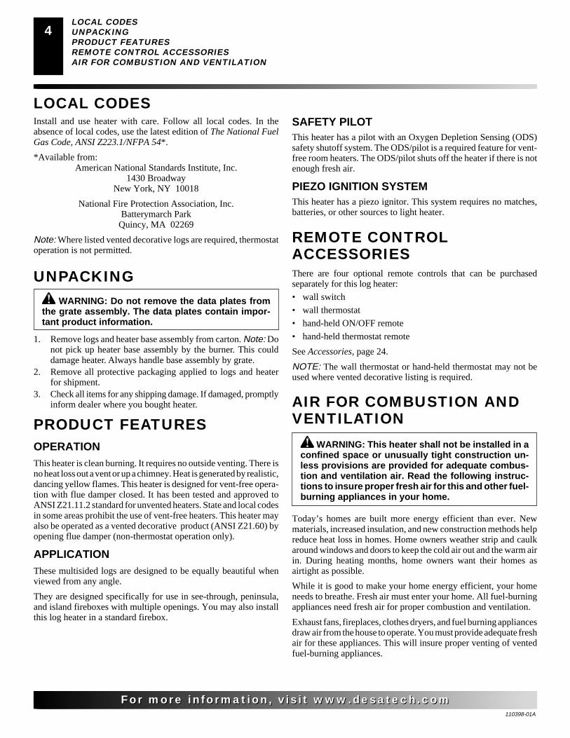
AIR FOR COMBUSTION ANDVENTILATION
Today’s homes are built more energy efficient than ever. Newmaterials, increased insulation, and new construction methods helpreduce heat loss in homes. Home owners weather strip and caulkaround windows and doors to keep the cold air out and the warm airin. During heating months, home owners want their homes asairtight as possible.
While it is good to make your home energy efficient, your homeneeds to breathe. Fresh air must enter your home. All fuel-burningappliances need fresh air for proper combustion and ventilation.
Exhaust fans, fireplaces, clothes dryers, and fuel burning appliancesdraw air from the house to operate. You must provide adequate freshair for these appliances. This will insure proper venting of ventedfuel-burning appliances.
WARNING: This heater shall not be installed in aconfined space or unusually tight construction un-less provisions are provided for adequate combus-tion and ventilation air. Read the following instruc-tions to insure proper fresh air for this and other fuel-burning appliances in your home.

110398-01A
For more information, visit www.desatech.comFor more information, visit www.desatech.com
55
PROVIDING ADEQUATE VENTILATIONThe following are excerpts from National Fuel Gas Code, ANSIZ223.1/NFPA 54, Section 5.3, Air for Combustion and Ventilation.
All spaces in homes fall into one of the three following ventilationclassifications:
1. Unusually Tight Construction2. Unconfined Space3. Confined Space
The information on pages 4 through 6 will help you classify yourspace and provide adequate ventilation.
Unusually Tight Construction
The air that leaks around doors and windows may provide enoughfresh air for combustion and ventilation. However, in buildings ofunusually tight construction, you must provide additional fresh air.
Unusually tight construction is defined as constructionwhere:a. walls and ceilings exposed to the outside atmosphere
have a continuous water vapor retarder with a ratingof one perm (6x10-11 kg per pa-sec-m2) or less withopenings gasketed or sealed and
b. weather stripping has been added on openable win-dows and doors and
c. caulking or sealants are applied to areas such asjoints around window and door frames, between soleplates and floors, between wall-ceiling joints, betweenwall panels, at penetrations for plumbing, electrical,and gas lines, and at other openings.
If your home meets all of the three criteria above, youmust provide additional fresh air. See Ventilation AirFrom Outdoors, page 6.
If your home does not meet all of the three criteria above,proceed to Determining Fresh-Air Flow For Heater Loca-tion, column 2.
Confined and Unconfined Space
The National Fuel Gas Code, ANSI Z223.1/NFPA 54 defines aconfined space as a space whose volume is less than 50 cubic feetper 1,000 Btu per hour (4.8 m3 per kw) of the aggregate input ratingof all appliances installed in that space and an unconfined space asa space whose volume is not less than 50 cubic feet per 1,000 Btu perhour (4.8 m3 per kw) of the aggregate input rating of all appliancesinstalled in that space. Rooms communicating directly with thespace in which the appliances are installed*, through openings notfurnished with doors, are considered a part of the unconfined space.
* Adjoining rooms are communicating only if there are doorlesspassageways or ventilation grills between them.
AIR FOR COMBUSTION ANDVENTILATIONContinued
DETERMINING FRESH-AIR FLOW FORHEATER LOCATION
Determining if You Have a Confined orUnconfined Space
Use this work sheet to determine if you have a confined or unconfined space.
Space: Includes the room in which you will install heater plus any adjoiningrooms with doorless passageways or ventilation grills between the rooms.
1. Determine the volume of the space (length x width x height).
Length x Width x Height = ___________ cu. ft. (volume of space)
Example: Space size 20 ft. (length) x 16 ft. (width) x 8 ft. (ceilingheight) = 2560 cu. ft. (volume of space)
If additional ventilation to adjoining room is supplied with grills or open-ings, add the volume of these rooms to the total volume of the space.
2. Multiply the space volume by 20 to determine the maximum Btu/Hrthe space can support.
__________ (volume of space) x 20 = (Maximum Btu/Hr the spacecan support)
Example: 2560 cu. ft. (volume of space) x 20 = 51,200 (maximumBtu/Hr the space can support)
3. Add the Btu/Hr of all fuel burning appliances in the space.
Vent-free heater _____________ Btu/Hr
Gas water heater* _____________ Btu/Hr
Gas furnace _____________ Btu/Hr
Vented gas heater _____________ Btu/Hr
Gas fireplace logs _____________ Btu/Hr
Other gas appliances* + _____________ Btu/Hr
Total = _____________ Btu/Hr
* Do not include direct-vent gas appliances. Direct-vent draws com-bustion air from the outdoors and vents to the outdoors.
Example:Gas water heater _____________ Btu/Hr
Vent-free heater + _____________ Btu/Hr
Total = _____________ Btu/Hr
4. Compare the maximum Btu/Hr the space can support with the actualamount of Btu/Hr used.
__________________ Btu/Hr (maximum the space can support)
__________________ Btu/Hr (actual amount of Btu/Hr used)
Example: 51,200 Btu/Hr (maximum the space can support)
73,000 Btu/Hr (actual amount of Btu/Hr used)
The space in the above example is a confined space because the actual Btu/Hrused is more than the maximum Btu/Hr the space can support. You mustprovide additional fresh air. See next page for your options.
40,000
33,000
73,000
AIR FOR COMBUSTION AND VENTILATIONProviding Adequate Ventilation
Determining Fresh-Air Flow For Heater Location

110398-01A
For more information, visit www.desatech.comFor more information, visit www.desatech.com
6
AIR FOR COMBUSTIONAND VENTILATIONContinued
A. Rework worksheet, adding the space of an adjoining room. If theextra space provides an unconfined space, remove door to adjoiningroom or add ventilation grills between rooms. See Ventilation Air FromInside Building below.
B. Vent room directly to the outdoors. See Ventilation Air From Out-doors.
C. Install a lower Btu/Hr heater, if lower Btu/Hr size makes room unconfined.
If the actual Btu/Hr used is less than the maximum Btu/Hr the space cansupport, the space is an unconfined space. You will need no additional freshair ventilation.
WARNING: If the area in which the heater may beoperated is smaller than that defined as an uncon-fined space or if the building is of unusually tightconstruction, provide adequate combustion and ven-tilation air by one of the methods described in theNational Fuel Gas Code, ANSI Z223.1/NFPA 54, Sec-tion 5.3 or applicable local codes.
VENTILATION AIR
Ventilation Air From Inside Building
This fresh air would come from an adjoining unconfined space.When ventilating to an adjoining unconfined space, you mustprovide two permanent openings: one within 12" of the ceiling andone within 12" of the floor on the wall connecting the two spaces(see options 1 and 2, Figure 2). You can also remove door intoadjoining room (see option 3, Figure 2). Follow the National FuelGas Code, ANSI Z223.1/NFPA 54, Section 5.3, Air for Combustionand Ventilation for required size of ventilation grills or ducts.
Ventilation Air From Outdoors
Provide extra fresh air by using ventilation grills or ducts. You mustprovide two permanent openings: one within 12" of the ceiling andone within 12" of the floor. Connect these items directly to theoutdoors or spaces open to the outdoors. These spaces include atticsand crawl spaces. Follow the National Fuel Gas Code, ANSI Z223.1/NFPA 54, Section 5.3, Air for Combustion and Ventilation forrequired size of ventilation grills or ducts.
IMPORTANT: Do not provide openings for inlet or outlet air intoattic if attic has a thermostat-controlled power vent. Heated airentering the attic will activate the power vent.
Figure 3 - Ventilation Air from Outdoors
Figure 2 - Ventilation Air from Inside Building
OutletAir
VentilatedAttic
OutletAir
InletAir
Inlet Air Ventilated Crawl Space
To CrawlSpace
To Attic
OrRemoveDoor intoAdjoining
Room,Option
3
Ventilation Grills Into Adjoining Room,
Option 2
VentilationGrills
Into Adjoining Room,
Option 1
12"
12"
AIR FOR COMBUSTION AND VENTILATIONDetermining Fresh-Air Flow For Heater Location (Cont.)Ventilation

110398-01A
For more information, visit www.desatech.comFor more information, visit www.desatech.com
77
INSTALLATION AND CLEARANCES(Vent-Free Operation Only)
WARNING: Maintain the minimum clearances. Ifyou can, provide greater clearances from floor, ceil-ing, and adjoining wall.
WARNING: Never install the heater• in a bedroom or bathroom unless installed as a
vented appliance, see page 10• in a recreational vehicle• where curtains, furniture, clothing, or other flam-
mable objects are less than 42 inches from thefront, top, or sides of the heater
• in high traffic areas• in windy or drafty areas
INSTALLATION
WARNING: A qualified service person must in-stall heater. Follow all local codes.
WARNING: Before installing in a solid fuel burn-ing fireplace, the chimney flue and firebox must becleaned of soot, creosote, ashes and loose paint bya qualified chimney cleaner. Creosote will ignite ifhighly heated. A dirty chimney flue may create anddistribute soot within the house. Inspect chimneyflue for damage. If damaged, operate heater with fluedamper closed.
WARNING: Seal any fresh air vents or ash clean-out doors located on floor or wall of fireplace. If not,drafting may cause pilot outage or sooting. Use aheat-resistant sealant. Do not seal chimney fluedamper.
CAUTION: This heater creates warm air currents.These currents move heat to wall surfaces next toheater. Installing heater next to vinyl or cloth wallcoverings or operating heater where impurities (suchas, but not limited to, tobacco smoke, aromaticcandles, cleaning fluids, oil or kerosene lamps, etc.)in the air exist, may discolor walls or cause odors.
IMPORTANT: Vent-free heaters add moisture to the air. Althoughthis is beneficial, installing heater in rooms without enough venti-lation air may cause mildew to form from too much moisture. SeeAir for Combustion and Ventilation, pages 4 through 6.
CHECK GAS TYPEUse only the correct type of gas (natural or propane/LP). If your gassupply is not the correct gas type, do not install heater. Call dealerwhere you bought heater for proper type heater.
NOTICE: This heater is intended for use as supple-mental heat. Use this heater along with your primaryheating system. Do not install this heater as yourprimary heat source. If you have a central heatingsystem, you may run system’s circulating blowerwhile using heater. This will help circulate the heatthroughout the house. In the event of a power outage,you can use this heater as your primary heat source.
LOG SIZING REQUIREMENTSLog Minimum FireboxSize Height Depth Width
27" 17" 19" 32"
MINIMUM FIREPLACECLEARANCE TO
COMBUSTIBLE MATERIALSLog Size Side Wall Ceiling
27" 16" 42"
NOTICE: State or local codes may only allow opera-tion of this appliance in a vented configuration. Checkyour state or local codes.
Carefully follow the instructions starting on page 8. This will ensuresafe installation into a masonry, UL127-listed manufactured fire-place, or listed vent-free firebox.
INSTALLATIONCheck Gas Type
Installation and Clearances

110398-01A
For more information, visit www.desatech.comFor more information, visit www.desatech.com
8
INSTALLATIONContinued
Minimum Noncombustible Material Clearances
If Not Using Mantel
Note: If using a mantel, proceed to If Using Mantel. If not using amantel, follow the information below.
You must have noncombustible material(s) above both fireplaceopenings. Noncombustible materials (such as slate, marble, tile,etc.) must be at least 1/2 inch thick. With sheet metal, you must havenoncombustible material behind it. Noncombustible material mustextend at least 8" up (for all models). If noncombustible material isless than 12", you must install the fireplace hood accessory. SeeFigure 5 at right for minimum clearances.
IMPORTANT: If you cannot meet these minimum clearances, youmust operate heater with chimney flue damper open. Go to Install-ing Damper Clamp Accessory for Vented Operation, page 10.
Noncombustible Requirements forMaterial Distance (A) Safe Installation
12" or more Noncombustible material OK.
Between 8" and 12" Install fireplace hood accessory(GA6050, GA6052 or GA6053, seeAccessories, page 24).
Less than 8" Noncombustible material must beextended to at least 8". See Be-tween 8" and 12", above. If youcannot extend material, you mustoperate heater with flue damperopen.
NOTICE: Manual control heaters may be used as avented product. If so, you must always run heater withchimney flue damper open. If running heater withdamper open, noncombustible material above fire-place opening is not needed. Go to Installing DamperClamp Accessory for Vented Operation, page 10.
Figure 5 - Heat Resistant Material (Slate, Marble, Tile, etc.)Above Fireplace
Heat ResistantMaterial
(A)
Figure 4 - Minimum Clearance for Combustible to Wall
*Minimum 16 inches from Side Wall
*
Example
Minimum Clearances For Side CombustibleMaterial, Side Wall, and CeilingA. Clearances from the side of the fireplace cabinet to any com-
bustible material and wall should follow diagram in Figure 4.
Example: The face of a mantel, bookshelf, etc. is made ofcombustible material and protrudes 3 1/2" from the wall. Thiscombustible material must be 4" from the side of the fireplacecabinet (see Figure 4).
Note: When installing your gas logs into a manufactured fire-box, follow firebox manufacturer’s instructions for minimumclearances to combustible materials.
B. Clearances from the top of the fireplace opening to the ceilingshould not be less than 42 inches.
If Using Mantel
You must have noncombustible material(s) above the fireplaceopening. Noncombustible materials (such as slate, marble, tile, etc.)must be at least 1/2 inch thick. With sheet metal, you must havenoncombustible material behind it. Noncombustible material mustextend at least 8 inches up (for all models). If noncombustible materialis less than 12", you must install the fireplace hood accessory. Evenif noncombustible material is more than 12", you may need the hoodaccessory to deflect heat away from your mantel shelf. See Figure 5and Figures 6 and 7, page 9, for minimum clearances.
INSTALLATIONInstallation and Clearances (Cont.)

110398-01A
For more information, visit www.desatech.comFor more information, visit www.desatech.com
99
INSTALLATIONContinued
FLOOR CLEARANCESA. If installing appliance on the floor level, you must maintain
the minimum distance of 14" to combustibles (see Figure 8).
B. If combustible materials are less than 14" to the fireplace, youmust install appliance at least 5" above the combustible floor-ing (see Figure 9).
NOTICE: If your installation does not meet the mini-mum clearances shown, you must do one of thefollowing:• operate the logs only with the flue damper open• raise the mantel to an acceptable height• remove the mantel
NOTICE: Surface temperatures of adjacent walls andmantels become hot during operation. Walls andmantels above the firebox may become hot to thetouch. If installed properly, these temperatures meetthe requirement of the national product standard.Follow all minimum clearances shown in this manual.
Figure 7 - Minimum Mantel Clearances When Using Hood
Figure 6 - Minimum Mantel Clearances Without Using Hood
Minimum Non-Combustible Material
Minimum Non-Combustible Material Height
Distances to Underside ofMantel
Top of FireplaceOpening
Underside ofMantel Shelf
Mantel Shelf
12"
(A)
18" 20" 22" 24"
All minimum distances arein inches
2 1/2"
6"
8"
10"
Minimum Non-Combustible Material 8"
Min.12" 15" 18"
All minimum distances arein inches
20"
2 1/2"
6"
8"
10"
12"
Distances to Underside ofMantel
Hood(GA6050, GA6052)
Top of FireplaceOpening
Underside ofMantel Shelf
Mantel Shelf
Figure 8 - Minimum Fireplace Clearances If Installed at FloorLevel
Figure 9 - Minimum Fireplace Clearances Above CombustibleFlooring
14"Min.
Combustible Material
Non-Combustible Material
Hearth
5"Min.
Combustible Material
Hearth CombustibleMaterial5”
Min.
Hood (GA6050,GA6052 or GA6053)
MANTEL CLEARANCESIn addition to meeting noncombustible material clearances, youmust also meet required clearances between fireplace openings andmantel shelf on each side of the fireplace. If you do not meet theclearances listed in this section, you will need a hood.
Determining Minimum Mantel Clearance
If you meet minimum clearance between mantel shelf and top offireplace opening, a hood is not required (see Figure 6).
Determining Minimum Mantel Clearance Whenusing a Hood
If minimum clearances in Figure 6 are not met, you must have ahood. When using a hood there are still certain minimum mantelclearances required. Follow minimum clearances shown in Figure7 when using hood.
INSTALLATIONMantel Clearances
Floor Clearances

110398-01A
For more information, visit www.desatech.comFor more information, visit www.desatech.com
10
Area of Various StandardRound Flues
Diameter (ins.) Area (sq. ins.)5" 20 sq. inches6" 29 sq. inches7" 39 sq. inches8" 51 sq. inches
INSTALLING DAMPER CLAMP ACCESSORYFOR VENTED OPERATIONNote: When used as a vented heater, appliance must be installedonly in a solid-fuel burning fireplace with a working flue andconstructed of noncombustible material.
If your heater is a manually controlled model, you may use thisheater as a vented product. There are three reasons for operatingyour heater in the vented mode:1. The fireplace does not meet the clearance to combustibles re-
quirements for vent-free operation2. State or local codes do not permit vent-free operation3. You prefer vented operation
If reasons number 1 or 2 above apply to you, you must permanentlyopen chimney flue damper. You must install the damper clampaccessory (to order, see Accessories, page 24). This will insure ventedoperation (see Figure 10). The damper clamp will keep damper open.Installation instructions are included with clamp accessory.
See chart below for minimum permanent flue opening you mustprovide. Attach damper clamp so the minimum permanent flueopening will be maintained at all times.
Chimney Minimum PermanentHeight (ft.) Flue Opening (sq. ins.)
6' to 15' 39 sq. inches15' to 30' 29 sq. inches
Figure 10 - Attaching Damper ClampMasonry Fireplace Manufactured Fireplace
Damper
Damper
DamperClamp
INSTALLING HEATER BASE ASSEMBLY
WARNING: If installing in a sunken fireplace, specialcare is needed. You must raise the fireplace floor toallow access to heater control panel. This will insureadequate air flow and guard against sooting and con-trols being damaged. Raise fireplace floor with non-combustible material. Make sure material is secure.
CAUTION: Do not pick up heater base assembly bythe burner. This could damage heater. Only handlebase assembly by grates.
WARNING: You must secure this heater to fire-place floor. If not, heater will move when you adjustcontrols. Moving heater may cause a gas leak.
IMPORTANT: Make sure the heater burner is level. If heater is notlevel, heater will not work properly.
Installation Items Needed• hardware package (provided with heater)
• approved flexible gas hose (not provided) (if allowed by local codes)
• sealant (resistant to propane/LP gas, not provided)
• electric drill with 3/16" drill bit (metal or masonry as applicable)
• flathead screwdriver
1. Apply pipe joint sealant lightly to male NPT threads of thefitting to be threaded into gas control. Connect approved flex-ible gas hose to gas control fitting in heater (see Figure 11).IMPORTANT: Hold gas fitting with wrench when connect-ing flexible gas hose.
2. Locate two masonry screws in hardware package.
3. Place heater base in fireplace.
WARNING: Do not remove the data plates at-tached to the heater base assembly. The data platescontain important warranty and safety information.
INSTALLATIONContinued
Fitting
Flexible GasHose (if allowedby local codes)
Figure 11 - Attaching Flexible Gas Hose to Heater
INSTALLATIONInstalling Damper Clamp Accessory For Vented OperationInstalling Heater Base Assembly
DamperClamp

110398-01A
For more information, visit www.desatech.comFor more information, visit www.desatech.com
1111
4. Place logs in their proper position on heater base. See Install-ing Logs, page 13.
5. Center heater base and logs front-to-back and side-to-side infireplace.
6. Carefully remove logs without moving heater base.
7. Mark screw locations through one hole on each side of themounting bracket (see Figure 12). If installing in a brick-bot-tom fireplace, mark screw locations in mortar joint of bricks.
8. Remove heater base from fireplace. If installing optional con-trol accessories, do so at this time. Follow all directions pro-vided with accessory.
9. Drill holes at marked locations using 3/16" drill bit.
10. Attach base assembly to fireplace floor using two masonryscrews (in hardware package).
INSTALLATIONContinued
O
FF
P
ILOT
O
N
H
I
LO
Figure 12 - Attaching Base Assembly to Fireplace Floor
Masonry Screw
Mounting Flanges
CONNECTING TO GAS SUPPLY
WARNING: A qualified service person must con-nect heater to gas supply. Follow all local codes.
WARNING: Never connect propane/LP heater di-rectly to the propane/LP supply. This heater requires anexternal regulator (not supplied). Install the externalregulator between the heater and propane/LP supply.
Installation Items Needed
Before installing heater, make sure you have the items listed below.
• external regulator (for propane/LP units only, supplied by installer)• piping (check local codes) • sediment trap• sealant (resistant to propane/LP gas) • tee joint• equipment shutoff valve * • pipe wrench• test gauge connection *
WARNING: Never connect natural gas heater toprivate (non-utility) gas wells. This gas is commonlyknown as wellhead gas.
INSTALLATIONInstalling Heater Base Assembly (Cont.)
Connecting To Gas Supply
* A CSA design-certified equipment shutoff valve with 1/8" NPTtap is an acceptable alternative to test gauge connection. Purchasethe optional CSA design-certified equipment shutoff valve fromyour dealer. See Accessories, page 24.
For propane/LP units, the installer must supply an external regula-tor. The external regulator will reduce incoming gas pressure. Youmust reduce incoming gas pressure to between 11 and 14 inches ofwater. If you do not reduce incoming gas pressure, heater regulatordamage could occur. Install external regulator with the vent point-ing down as shown in Figure 13. Pointing the vent down protects itfrom freezing rain or sleet.
Installation must include an equipment shutoff valve, union, andplugged 1/8" NPT tap. Locate NPT tap within reach for test gauge hookup. NPT tap must be upstream from heater (see Figure 14, page 12).
IMPORTANT: Install equipment shutoff valve in an accessiblelocation. The equipment shutoff valve is for turning on or shuttingoff the gas to the appliance.
Check your building codes for any special requirements for locatingequipment shutoff valve to fireplaces.
Apply pipe joint sealant lightly to male NPT threads. This willprevent excess sealant from going into pipe. Excess sealant in pipecould result in clogged heater valves.
CAUTION: Use only new, black iron or steel pipe.Internally-tinned copper tubing may be used in certainareas. Check your local codes. Use pipe of 1/2" diam-eter or greater to allow proper gas volume to heater. Ifpipe is too small, undue loss of volume will occur.
WARNING: Use pipe joint sealant that is resistantto liquid petroleum (LP) gas.
Figure 13 - External Regulator With Vent Pointing Down(propane/LP gas only)
Propane/LPSupply Tank
ExternalRegulator
VentPointingDown
110398-01A
For more information, visit www.desatech.comFor more information, visit www.desatech.com
12INSTALLATION
Connecting To Gas Supply (Cont.)Checking Gas Connections
INSTALLATIONContinued
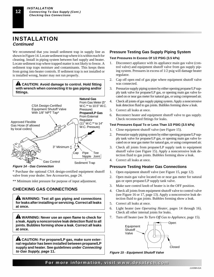
We recommend that you install sediment trap in supply line asshown in Figure 14. Locate sediment trap where it is within reach forcleaning. Install in piping system between fuel supply and heater.Locate sediment trap where trapped matter is not likely to freeze. Asediment trap traps moisture and contaminants. This keeps themfrom going into heater controls. If sediment trap is not installed oris installed wrong, heater may not run properly.
CAUTION: Avoid damage to control. Hold fittingwith wrench when connecting it to gas piping and/orfittings.
* Purchase the optional CSA design-certified equipment shutoffvalve from your dealer. See Accessories, page 24.
** Minimum inlet pressure for purpose of input adjustment.
Figure 14 - Gas ConnectionGas Control
3" Minimum
CSA Design-CertifiedEquipment Shutoff ValveWith 1/8" NPT Tap*
Approved FlexibleGas Hose (if allowedby local codes)
Cap Pipe TeeNipple Joint
Sediment Trap
Natural GasFrom Gas Meter (5"W.C.** to 10.5" W.C.Pressure)Propane/LP GasFrom ExternalRegulator(11" W.C.** to 14"W.C. Pressure)
WARNING: Test all gas piping and connectionsfor leaks after installing or servicing. Correct all leaksat once.
CHECKING GAS CONNECTIONS
WARNING: Never use an open flame to check fora leak. Apply a noncorrosive leak detection fluid to alljoints. Bubbles forming show a leak. Correct all leaksat once.
CAUTION: For propane/LP gas, make sure exter-nal regulator has been installed between propane/LPsupply and heater. See guidelines under Connectingto Gas Supply, page 11.
Pressure Testing Gas Supply Piping System
Test Pressures In Excess Of 1/2 PSIG (3.5 kPa)
1. Disconnect appliance with its appliance main gas valve (con-trol valve) and equipment shutoff valve from gas supply pip-ing system. Pressures in excess of 1/2 psig will damage heaterregulator.
2. Cap off open end of gas pipe where equipment shutoff valvewas connected.
3. Pressurize supply piping system by either opening propane/LP sup-ply tank valve for propane/LP gas, or opening main gas valve lo-cated on or near gas meter for natural gas, or using compressed air.
4. Check all joints of gas supply piping system. Apply a noncorrosiveleak detection fluid to gas joints. Bubbles forming show a leak.
5. Correct all leaks at once.
6. Reconnect heater and equipment shutoff valve to gas supply.Check reconnected fittings for leaks.
Test Pressures Equal To or Less Than 1/2 PSIG (3.5 kPa)
1. Close equipment shutoff valve (see Figure 15).
2. Pressurize supply piping system by either opening propane/LP sup-ply tank valve for propane/LP gas, or opening main gas valve lo-cated on or near gas meter for natural gas, or using compressed air.
3. Check all joints from propane/LP supply tank to equipmentshutoff valve (see Figure 15). Apply a noncorrosive leak de-tection fluid to gas joints. Bubbles forming show a leak.
4. Correct all leaks at once.
Pressure Testing Heater Gas Connections1. Open equipment shutoff valve (see Figure 15, page 12).
2. Open main gas valve located on or near gas meter for naturalgas or open propane/LP supply tank valve.
3. Make sure control knob of heater is in the OFF position.
4. Check all joints from equipment shutoff valve to control valve(see Figure 16 or 17, page 13). Apply a noncorrosive leak de-tection fluid to gas joints. Bubbles forming show a leak.
5. Correct all leaks at once.
6. Light heater (see Operating Heater, pages 14 through 16).Check all other internal joints for leaks.
7. Turn off heater (see To Turn Off Gas to Appliance, page 15).ON
POSITION
OFFPOSITION
Figure 15 - Equipment Shutoff Valve
Open
Closed
EquipmentShutoffValve
110398-01A
For more information, visit www.desatech.comFor more information, visit www.desatech.com
1313
O
FF
P
ILOT
O
N
H
I
LO
O
FF
P
ILOT
O
N
H
I
LO
INSTALLATIONChecking Gas Connections (Cont.)
Installing Logs
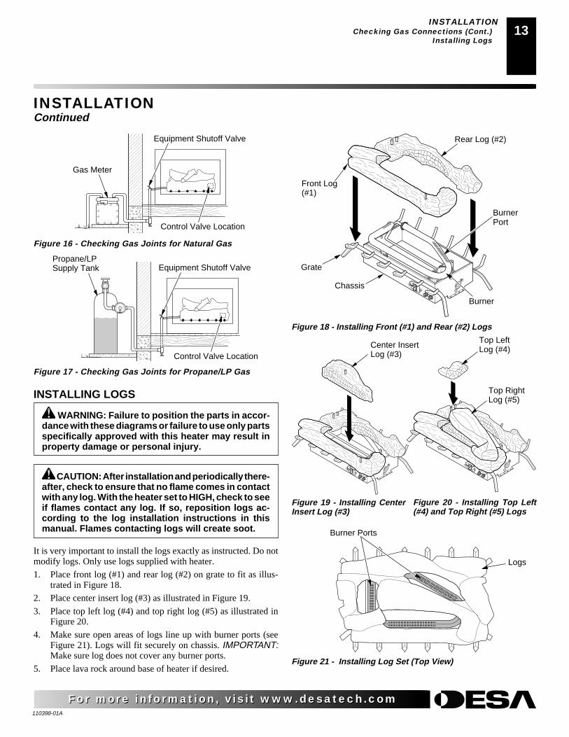
Figure 17 - Checking Gas Joints for Propane/LP Gas
Control Valve Location
Propane/LPSupply Tank Equipment Shutoff Valve
Figure 16 - Checking Gas Joints for Natural Gas
Gas Meter
Equipment Shutoff Valve
Control Valve Location
INSTALLATIONContinued
WARNING: Failure to position the parts in accor-dance with these diagrams or failure to use only partsspecifically approved with this heater may result inproperty damage or personal injury.
INSTALLING LOGS
It is very important to install the logs exactly as instructed. Do notmodify logs. Only use logs supplied with heater.
1. Place front log (#1) and rear log (#2) on grate to fit as illus-trated in Figure 18.
2. Place center insert log (#3) as illustrated in Figure 19.
3. Place top left log (#4) and top right log (#5) as illustrated inFigure 20.
4. Make sure open areas of logs line up with burner ports (seeFigure 21). Logs will fit securely on chassis. IMPORTANT:Make sure log does not cover any burner ports.
5. Place lava rock around base of heater if desired.
CAUTION: After installation and periodically there-after, check to ensure that no flame comes in contactwith any log. With the heater set to HIGH, check to seeif flames contact any log. If so, reposition logs ac-cording to the log installation instructions in thismanual. Flames contacting logs will create soot.
Figure 18 - Installing Front (#1) and Rear (#2) Logs
Rear Log (#2)
Burner
Chassis
Grate
BurnerPort
Front Log(#1)
Figure 19 - Installing CenterInsert Log (#3)
Logs
Burner Ports
Figure 20 - Installing Top Left(#4) and Top Right (#5) Logs
Figure 21 - Installing Log Set (Top View)
Center InsertLog (#3)
O
FF
P
ILOT
O
N
H
I
LO
Top LeftLog (#4)
Top RightLog (#5)

110398-01A
For more information, visit www.desatech.comFor more information, visit www.desatech.com
14OPERATING HEATER
For Your Safety Read Before LightingLighting Instructions
OPERATING HEATERFOR YOUR SAFETY READ
BEFORE LIGHTING
WARNING: If you do not follow these instructionsexactly, a fire or explosion may result causing prop-erty damage, personal injury or loss of life.
A. This appliance has a pilot which must be lighted by hand.When lighting the pilot, follow these instructions exactly.
B. BEFORE LIGHTING smell all around the appliance areafor gas. Be sure to smell next to the floor because some gasis heavier than air and will settle on the floor.WHAT TO DO IF YOU SMELL GAS• Do not try to light any appliance.• Do not touch any electric switch; do not use any phone
in your building.• Immediately call your gas supplier from a neighbor’s
phone. Follow the gas supplier’s instructions.• If you cannot reach your gas supplier, call the fire de-
partment.C. Use only your hand to push in or turn the gas control knob.
Never use tools. If the knob will not push in or turn byhand, don’t try to repair it, call a qualified service techni-cian or gas supplier. Force or attempted repair may resultin a fire or explosion.
D. Do not use this appliance if any part has been under water.Immediately call a qualified service technician to inspectthe appliance and to replace any part of the control systemand any gas control which has been under water.
1. STOP! Read the safety information, column 1.2. Make sure equipment shutoff valve is fully open.3. Set switch in OFF position.
LIGHTING INSTRUCTIONS
WARNING:• If fireplace has glass doors, never operate this
heater with glass doors closed. If you operate heaterwith doors closed, heat buildup inside fireplace willcause glass to burst. Also if fireplace opening hasvents at the bottom, you must open the vents beforeoperating heater.
• You must operate this heater with a fireplace screenin place. Make sure fireplace screen is closedbefore running heater.
NOTICE: During initial operation of new heater, burninglogs will give off a paper-burning smell. Open damper orwindow to vent smell. This will only last a few hours.
Note: Homeowners generally prefer to operate their heaterwith the chimney damper closed. This will put all the heat intothe room. However, there may be times you will desire the fullflames of the HI heat setting but will find the heat outputexcessive. You can open the chimney damper (if you have one)fully or partially to release some of the heat.
WARNING: Damper handle will be hot if heaterhas been running.
WARNING: Burner will come on automaticallywithin one minute when the selector switch is in theON position after the pilot is lit.
4. Press in and turn control knob clockwise to theOFF position.
5. Wait five (5) minutes to clear out any gas. Then smell forgas, including near the floor. If you smell gas, STOP! Fol-low “B” in the safety information, column 1. If you don’tsmell gas, go to the next step.
6. Press in and turn control knob counterclockwise to the PILOT position. Press in control knob for five (5)seconds (see Figure 22).Note: You may be running this heater for the first timeafter hooking up to gas supply. If so, the control knob mayneed to be pressed in for 30 seconds or more. This will al-low air to bleed from the gas system.
7. With control knob pressed in, press and release ignitorbutton. This will light pilot. The pilot is attached to the frontburner. If needed, keep pressing ignitor button until pilotlights.Note: If pilot does not stay lit, contact a qualified serviceperson or gas supplier for repairs. Until repairs are made,light pilot with match. To light pilot with match, see ManualLighting Procedure on page 15.
Figure 22 - Control Knob and Ignitor Button Location (Shown asSupplied, No Control Options)
OFF
PILOTON
L O
IH
AUTOOFFON
Control KnobIgnitor Button Selector Switch
Flame Adjustment Knob
110398-01A
For more information, visit www.desatech.comFor more information, visit www.desatech.com
1515OPERATING HEATER
LIghting Instructions (Cont.)To Turn Off Gas To Appliance
Manual Lighting ProcedureOptional Remote Operation
CAUTION: Do not try to adjust heating levels byusing the equipment shutoff valve.
WARNING: Make sure the selector switch is in theOFF position when you are away from home for longperiods of time. Heater will come on automaticallywith selector switch in the ON position.
OPERATING HEATERContinued
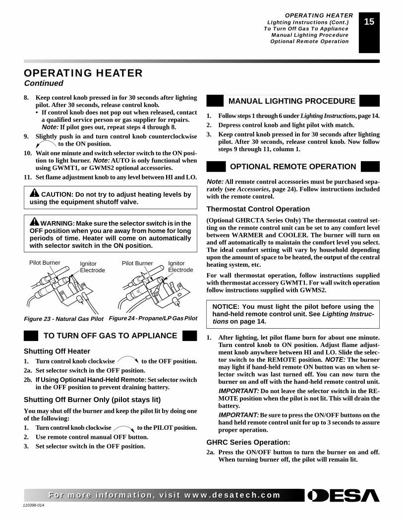
8. Keep control knob pressed in for 30 seconds after lightingpilot. After 30 seconds, release control knob.• If control knob does not pop out when released, contact
a qualified service person or gas supplier for repairs.Note: If pilot goes out, repeat steps 4 through 8.
9. Slightly push in and turn control knob counterclockwise to the ON position.
10. Wait one minute and switch selector switch to the ON posi-tion to light burner. Note: AUTO is only functional whenusing GWMT1, or GWMS2 optional accessories.
11. Set flame adjustment knob to any level between HI and LO.
IgnitorElectrode
Pilot Burner
Figure 24 - Propane/LP Gas PilotFigure 23 - Natural Gas Pilot
IgnitorElectrode
Pilot Burner
TO TURN OFF GAS TO APPLIANCE
Shutting Off Heater1. Turn control knob clockwise to the OFF position.2a. Set selector switch in the OFF position.2b. If Using Optional Hand-Held Remote: Set selector switch
in the OFF position to prevent draining battery.
Shutting Off Burner Only (pilot stays lit)
You may shut off the burner and keep the pilot lit by doing oneof the following:1. Turn control knob clockwise to the PILOT position.2. Use remote control manual OFF button.3. Set selector switch in the OFF position.
MANUAL LIGHTING PROCEDURE
Note: All remote control accessories must be purchased sepa-rately (see Accessories, page 24). Follow instructions includedwith the remote control.
Thermostat Control Operation
(Optional GHRCTA Series Only) The thermostat control set-ting on the remote control unit can be set to any comfort levelbetween WARMER and COOLER. The burner will turn onand off automatically to maintain the comfort level you select.The ideal comfort setting will vary by household dependingupon the amount of space to be heated, the output of the centralheating system, etc.
For wall thermostat operation, follow instructions suppliedwith thermostat accessory GWMT1. For wall switch operationfollow instructions supplied with GWMS2.
1. Follow steps 1 through 6 under Lighting Instructions, page 14.2. Depress control knob and light pilot with match.3. Keep control knob pressed in for 30 seconds after lighting
pilot. After 30 seconds, release control knob. Now followsteps 9 through 11, column 1.
OPTIONAL REMOTE OPERATION
NOTICE: You must light the pilot before using thehand-held remote control unit. See Lighting Instruc-tions on page 14.
1. After lighting, let pilot flame burn for about one minute.Turn control knob to ON position. Adjust flame adjust-ment knob anywhere between HI and LO. Slide the selec-tor switch to the REMOTE position. NOTE: The burnermay light if hand-held remote ON button was on when se-lector switch was last turned off. You can now turn theburner on and off with the hand-held remote control unit.IMPORTANT: Do not leave the selector switch in the RE-MOTE position when the pilot is not lit. This will drain thebattery.IMPORTANT: Be sure to press the ON/OFF buttons on thehand held remote control unit for up to 3 seconds to assureproper operation.
GHRC Series Operation:2a. Press the ON/OFF button to turn the burner on and off.
When turning burner off, the pilot will remain lit.

110398-01A
For more information, visit www.desatech.comFor more information, visit www.desatech.com
16
GHRCTA Series Operation2b. Press the AUTO/ON/OFF button on the hand-held remote
control (see Figure 26). The lights to the left of the buttonwill show AUTO, ON, or OFF.• In the ON mode, the burners will ignite. The heater is in
manual mode when ON is lit.• In the AUTO mode, the thermostat in the hand-held re-
mote unit controls the room temperature. To increase theroom temperature, press the top arrow of the TEMP but-ton. To lower the room temperature, press the bottomarrow of the TEMP button. At higher settings the heaterwill run longer.IMPORTANT: This remote control has been specially en-gineered to take an air temperature sample every 5.5minutes in the AUTO mode. It will not respond immedi-ately to the temperature setting being turned up or down.IMPORTANT: The hand-held remote control unit mustbe near the heater. Do not keep the hand-held remotecontrol unit too close to the heater. The thermostat onthe hand-held remote control unit will heat up too quicklyand turn the heater off.
3. To turn the burner off, press the AUTO/ON/OFF buttonuntil OFF lights. The pilot will remain lit.IMPORTANT: To turn the pilot off, manually turn the con-trol knob on the heater to the OFF position.
OPERATING HEATEROptional Remote Operation (Cont.)
INSPECTING BURNERSPilot Flame PatternBurner Flame Pattern
OPERATING HEATERContinued
Figure 26 - Thermostat Hand-Held Remote Control UnitSelections (GHRCTA only)
Figure 25 - Setting the Selector Switch, Control Knob, andFlame Adjustment Knob for Remote Operation
Selector Switch in Remote Position(Optional Remote Control)
ONOFFREMOTE
OFF
PILOTO
N
L O
IH
Control Knob inOn PositionFlame Adjustment Knob
Increases RoomTemperature inAUTO Mode
Decreases RoomTemperature inAUTO Mode
Turns BurnersOn or Off andAllows You toChoose the AutoSetting
ShowsTemperatureSetting
The Log Heaterwill AutomaticallyCycle betweenPilot and the HeatSetting that hasbeen Selected
Figure 27 - Correct Pilot Flame Pattern (Propane/LP Pilot Shown)
Pilot BurnerThermocouple
Figure 28 - Incorrect Pilot Flame Pattern (Propane/LP PilotShown)
Check pilot flame pattern and burner flame patterns often.
PILOT FLAME PATTERNFigure 27 shows a correct pilot flame pattern. Figure 28 shows anincorrect pilot flame pattern. The incorrect pilot flame is nottouching the thermocouple. When the thermocouple cools, theheater will shut down.
If pilot flame pattern is incorrect, as shown in Figure 28
• turn heater off (see To Turn Off Gas to Appliance, page 15)
• see Troubleshooting, pages 18 through 20
Note: The pilot flame on natural gas units will have a slight curve,but flame should be blue and have no yellow or orange color.
Pilot Burner
INSPECTING BURNERS
Thermocouple
BURNER FLAME PATTERNFigure 29 shows a correct burner flame pattern. Figure 30 shows anincorrect burner flame pattern. If burner flame pattern is incorrect,
• turn heater off (see To Turn Off Gas to Appliance, page 15)
• see Troubleshooting, pages 18 through 20
Figure 29 - Correct Flame Pattern
Figure 30 - Incorrect Flame Pattern

110398-01A
For more information, visit www.desatech.comFor more information, visit www.desatech.com
1717INSPECTING BURNERS
Burner Flame Pattern (Cont.)CLEANING AND MAINTENANCE
Cleaning Burner Injector Holder And Pilot Air Inlet HoleLogs
Main Burner
INSPECTING BURNERSContinued
BURNER PRIMARY AIR HOLESAir is drawn into the burner through the holes in the fitting at theburner entrance. These holes may become blocked with dust or lint.Periodically inspect these holes for any blockage and clean ifneeded. Blocked air holes will create soot.
MAIN BURNERPeriodically inspect all burner flame holes with the heater running. Allslotted burner flame holes should be open with yellow flame present.All round burner flame holes should be open with a small blue flamepresent. Some burner flame holes may become blocked by debris orrust, with no flame present. If so, turn off heater and let cool. Removeblockage, blocked burner flame holes will create soot.
CLEANING ANDMAINTENANCE
WARNING: Turn off heater and let cool beforecleaning.
CAUTION: You must keep control areas, burner,and circulating air passageways of heater clean.Inspect these areas of heater before each use. Haveheater inspected yearly by a qualified service per-son. Heater may need more frequent cleaning due toexcessive lint from carpeting, bedding material, pethair, etc.
CLEANING BURNER INJECTOR HOLDERAND PILOT AIR INLET HOLEThe primary air inlet holes allow the proper amount of air to mix withthe gas. This provides a clean burning flame. Keep these holes clearof dust, dirt, lint, and pet hair. Clean these air inlet holes prior to eachheating season. Blocked air holes will create soot. We recommendthat you clean the unit every three months during operation and haveheater inspected yearly by a qualified service person.
We also recommend that you keep the burner tube and pilotassembly clean and free of dust and dirt. To clean these parts werecommend using compressed air no greater than 30 PSI. Yourlocal computer store, hardware store, or home center may carrycompressed air in a can. You can use a vacuum cleaner in the blowposition. If using compressed air in a can, please follow thedirections on the can. If you don't follow directions on the can, youcould damage the pilot assembly.
1. Shut off the unit, including the pilot. Allow the unit to cool forat least thirty minutes.
2. Inspect burner, pilot, and primary air inlet holes on injectorholder for dust and dirt (see Figure 31).
3. Blow air through the ports/slots and holes in the burner.4. Check the injector holder located at the end of the burner tube
again. Remove any large particles of dust, dirt, lint, or pet hairwith a soft cloth or vacuum cleaner nozzle.
5. Blow air into the primary air holes on the injector holder.6. In case any large clumps of dust have now been pushed into
the burner repeat steps 3 and 4.
Clean the pilot assembly also. A yellow tip on the pilot flameindicates dust and dirt in the pilot assembly. There is a small pilotair inlet hole about two inches from where the pilot flame comes outof the pilot assembly (see Figure 32). With the unit off, lightly blowair through the air inlet hole. You may blow through a drinking strawif compressed air is not available.
Figure 31 - Injector Holder On Outlet Burner Tube
BurnerTube Injector Holder
(May Be Brass orAluminum Dependingon Model)
Primary Air Inlet Holes(Shape of Holes MayVary by Model)
Figure 32 - Pilot Inlet Air Hole
BurnerTube
Pilot Assembly
Pilot AirInlet Hole
Ports/Slots
LOGS• If you remove logs for cleaning, refer to Installing Logs, page
13, to properly replace logs.
• Replace log(s) if broken or chipped (dime-sized or larger).
MAIN BURNERPeriodically inspect all burner flame holes with the heater running. Allslotted burner flame holes should be open with yellow flame present.All round burner flame holes should be open with a small blue flamepresent. Some burner flame holes may become blocked by debris orrust, with no flame present. If so, turn off heater and let cool. Removeblockage, blocked burner flame holes will create soot.

110398-01A
For more information, visit www.desatech.comFor more information, visit www.desatech.com
18
TROUBLESHOOTING WARNING: Turn off heaterand let cool before servicing.Only a qualified service personshould service and repair heater.
CAUTION: Never use a wire,needle, or similar object to cleanODS/pilot. This can damage ODS/pilot unit.
POSSIBLE CAUSE
1. Ignitor electrode not connected to igni-tor cable
2. Ignitor cable pinched or wet
3. Piezo ignitor nut is loose
4. Broken ignitor cable5. Bad piezo ignitor6. Ignitor electrode broken7. Ignitor electrode positioned wrong
1. Gas supply turned off or equipmentshutoff valve closed
2. Control knob not in PILOT position3. Control knob not pressed in while in
PILOT position4. Air in gas lines when installed
5. Depleted gas supply (propane/LP gas)6. ODS/pilot is clogged
7. Gas regulator setting is not correct
1. Control knob not fully pressed in2. Control knob not pressed in long enough
3. Equipment shutoff valve not fully open4. Pilot flame not touching thermocouple,
which allows thermocouple to cool,causing pilot flame to go out. This prob-lem could be caused by one or both ofthe following:A) Low gas pressureB) Dirty or partially clogged ODS/pilot
5. Thermocouple connection loose at con-trol valve
6. Thermocouple damaged7. Control valve damaged
REMEDY
1. Reconnect ignitor cable
2. Free ignitor cable if pinched by anymetal or tubing. Keep ignitor cable dry
3. Tighten nut holding piezo ignitor to basepanel of log set. Nut is located behindbase panel.
4. Replace ignitor cable5. Replace piezo ignitor6. Replace pilot assembly7. Replace pilot assembly
1. Turn on gas supply or open equipmentshutoff valve
2. Turn control knob to PILOT position3. Press in control knob while in PILOT
position4. Continue holding down control knob.
Repeat igniting operation until air is re-moved
5. Contact local propane/LP gas company6. Clean ODS/pilot (see Cleaning and
Maintenance, page 17) or replace ODS/pilot assembly
7. Replace gas control
1. Press in control knob fully2. After ODS/pilot lights, keep control
knob pressed in 30 seconds3. Fully open equipment shutoff valve4. A) Contact local natural or propane/LP
gas company
B) Clean ODS/pilot (see Cleaning andMaintenance, page 17) or replace ODS/pilot assembly
5. Hand tighten until snug, then tighten1/4 turn more
6. Replace pilot assembly7. Replace control valve
OBSERVED PROBLEM
When ignitor button is pressed, there is nospark at ODS/pilot
When ignitor button is pressed, there isspark at ODS/pilot but no ignition
ODS/pilot lights but flame goes out whencontrol knob is released
Note: For additional help, visit DESAInternational’s technical service web siteat www.desatech.com.
Note: All troubleshooting items are listed inorder of operation.
TROUBLESHOOTING

110398-01A
For more information, visit www.desatech.comFor more information, visit www.desatech.com
1919
OBSERVED PROBLEM
Burner does not light after ODS/pilot is lit
Delayed ignition burner
Burner backfiring during combustion
Slight smoke or odor during initial operation
Moisture/condensation noticed on windows
Heater produces a whistling noise whenburner is lit
White powder residue forming within burnerbox or on adjacent walls or furniture
Remote does not function
REMEDY
1. Clean burner (see Cleaning and Mainte-nance, page 17) or replace burner orifice
2. Contact local natural or propane/LP gascompany
3. Reconnect leads (see Wiring Diagram,page 21)
4. Replace battery in transmitter and re-ceiver
1. Contact local natural or propane/LP gascompany
2. Clean burner (see Cleaning and Mainte-nance, page 17) or replace burner orifice
1. Clean burner (see Cleaning and Mainte-nance, page 17) or replace burner orifice
2. Replace damaged burner3. Replace gas control
1. Check burner for dirt and debris. Iffound, clean burner (see Cleaning andMaintenance, page 17)
2. Replace gas control3. Problem will stop after a few hours of
operation
1. Refer to Air for Combustion and Venti-lation requirements (page 4)
1. Turn control knob to LO position andlet warm up for a minute
2. Operate burner until air is removed fromline. Have gas line checked by localnatural or propane/LP gas company
3. Observe minimum installation clear-ances (see pages 7 through 9)
4. Clean burner (see Cleaning and Mainte-nance, page 17) or replace burner orifice
1. Turn heater off when using furniturepolish, wax, carpet cleaners, or similarproducts
1. Replace 9-volt batteries in receiver andremote control
TROUBLESHOOTINGContinued
POSSIBLE CAUSE
1. Burner orifice clogged
2. Inlet gas pressure is too low
3. Thermopile leads disconnected or im-properly connected
4. Burners will not come on in remoteposition
1. Manifold pressure is too low
2. Burner orifice clogged
1. Burner orifice is clogged or damaged
2. Damaged burner3. Gas regulator defective
1. Not enough air
2. Gas regulator defective3. Residues from manufacturing processes
and logs curing
1. Not enough combustion/ventilation air
1. Turning control knob to HI positionwhen burner is cold
2. Air in gas line
3. Air passageways on heater blocked
4. Dirty or partially clogged burner orifice
1. When heated, vapors from furniture pol-ish, wax, carpet cleaners, etc. may turninto white powder residue
1. Battery is not installed. Battery poweris low
TROUBLESHOOTING

110398-01A
For more information, visit www.desatech.comFor more information, visit www.desatech.com
20TROUBLESHOOTING
TROUBLESHOOTINGContinued
WARNING: If you smell gas• Shut off gas supply.• Do not try to light any appliance.• Do not touch any electrical switch; do not use any phone in your
building.• Immediately call your gas supplier from a neighbor’s phone. Follow the
gas supplier’s instructions.• If you cannot reach your gas supplier, call the fire department.
OBSERVED PROBLEM
Heater produces a clicking/ticking noisejust after burner is lit or shut off
Heater produces unwanted odors
Heater shuts off in use (ODS operates)
Gas odor even when control knob is in OFFposition
Gas odor during combustion
IMPORTANT: Operating heater where impurities in air exist may create odors. Cleaningsupplies, paint, paint remover, cigarette smoke, cements and glues, new carpet or textiles,etc., create fumes. These fumes may mix with combustion air and create odors. These odorswill disappear over time.
REMEDY
1. This is common with most heaters. Ifnoise is excessive, contact qualified ser-vice person
1. Open window and ventilate room. Stopusing odor causing products while heateris running
2. Locate and correct all leaks (see Check-ing Gas Connections, page 12)
1. Open window and/or door for ventilation2. Contact local natural or propane/LP gas
company3. Clean ODS/pilot (see Cleaning and
Maintenance, page 17)
1. Locate and correct all leaks (see Check-ing Gas Connections, page 12)
2. Replace control valve
1. Take apart gas tubing and remove for-eign matter
2. Locate and correct all leaks (see Check-ing Gas Connections, page 12)
POSSIBLE CAUSE
1. Metal expanding while heating or con-tracting while cooling
1. Heater burning vapors from paint, hairspray, glues, cleaners, chemicals, newcarpet, etc. (See IMPORTANT state-ment above)
2. Gas leak. See Warning statement attop of page
1. Not enough fresh air is available2. Low line pressure
3. ODS/pilot is partially clogged
1. Gas leak. See Warning statement attop of page
2. Control valve defective
1. Foreign matter between control valveand burner
2. Gas leak. See Warning statement attop of page

110398-01A
For more information, visit www.desatech.comFor more information, visit www.desatech.com
2121WIRING DIAGRAMSPECIFICATIONS
TECHNICAL SERVICEREPLACEMENT PARTS
SPECIFICATIONSNatural Gas Propane/LP
Btu (Variable) 20,000/39,000 20,000/39,000Type Gas Natural Gas Only Propane/LP OnlyIgnition Piezo PiezoPressure Manifold 3.5" W.C. 8.0" W.C.Inlet Gas Pressure (in. of water)
Maximum 10.5" 14"Minimum* 5" 11"
Shipping Weight 32 lbs. 32 lbs.
* For input adjustment
SERVICE HINTSWhen Gas Pressure Is Too Low• pilot will not stay lit
• burners will have delayed ignition
• heater will not produce specified heat
• propane/LP gas supply may be low
You may feel your gas pressure is too low. If so, contact your localnatural or propane/LP gas supplier.
TECHNICAL SERVICEYou may have further questions about installation, operation, ortroubleshooting. If so, contact DESA International’s TechnicalService Department at 1-866-672-6040. When calling please haveyour model and serial numbers of your heater ready.
You can also visit DESA International’s technical services web siteat www.desatech.com.
WIRING DIAGRAMNote: For proper operation of optional accessories, the wires fromthe switch to the control must be connected exactly as shown.
AUTOOFFON
Thermopile
REPLACEMENT PARTSNote: Use only original replacement parts. This will protect yourwarranty coverage for parts replaced under warranty.
PARTS UNDER WARRANTYContact authorized dealers of this product. If they can’t supplyoriginal replacement part(s), call DESA International’s TechnicalService Department at 1-866-672-6040. When calling DESA Inter-national, have ready
• your name and address
• model and serial numbers of your heater
• how heater was malfunctioning
• type of gas used (propane/LP or natural gas)
• purchase date
Usually, we will ask you to return the part to the factory.
PARTS NOT UNDERWARRANTYContact authorized dealers of this product. If they can’t supply originalreplacement part(s), call DESA International at 1-866-672-6040 forreferral information. When calling DESA International, have ready
• model number of your heater
• the replacement part number

110398-01A
For more information, visit www.desatech.comFor more information, visit www.desatech.com
22
5
O
FF
P
ILOT
O
N
H
I
LO
O
FF
P
ILOT
O
N
H
I
LO
1-3
1-1
1-5
1-4
1-2
9 3
2
13
12
1514
1817
12
12
16
21
12 19
6
8
74
1112
20 10
9
23
22
ILLUSTRATEDPARTSBREAKDOWNVYM27NR, VYM27PRFVFM27NR, FVFM27PR
NOTE: Part numbers 22and 23 are for natural gasmodels only.
ILLUSTRATED PARTS BREAKDOWNVYM27NR, VYM27PR, FVFM27NR, FVFM27PR

110398-01A
For more information, visit www.desatech.comFor more information, visit www.desatech.com
2323
PARTS LISTVYM27NRVYM27PRFVFM27NRFVFM27PR
This list contains replaceable parts used in your heater. When ordering parts, follow theinstructions listed under Replacement Parts on page 21 of this manual.
PART NUMBERKEY VYM27NR VYM27PRNO. FVFM27NR FVFM27PR DESCRIPTION QTY.
1a 104676-01 104676-01 1 Piece Log Set1b 110397-06 110397-06 5 Piece Log Set 1 1-1 110321-01 110321-01 Front Log (#1) 1 1-2 110321-02 110321-02 Rear Log (#2) 1 1-3 110321-05 110321-05 Center Insert Log (#3) 1 1-4 110321-03 110321-03 Top Left Log (#4) 1 1-5 110321-04 110321-04 Top Right Log (#5) 12 103779-01 103778-01 ODS Pilot 13 098249-01 098249-01 ODS Nut 24 104592-01 104592-02 Burner Outlet Tube 15 098264-02 098264-02 Male Connector 16 102843-01 102843-01 Burner Clip 17 099056-16 099056-17 Burner Orifice Injector 18 104591-01 104591-01 Burner 19 100609-01 099387-13 Pilot Tube (Regulator to Pilot) 110 103781-01 103781-02 Gas Control Valve 111 104611-01 104611-01 Lower Bracket 112 098304-01 098304-01 Screw, #8 x .38 713 104590-01CK 104590-01CK Painted Base Assy 114 098271-06 098271-06 Ignitor Cable 115 102445-01 102445-01 Piezo Ignitor 116 103587-02CK 103587-02CK Plate, Switch 117 103784-02 103784-02 Flame Adjustment Knob 118 103784-01 103784-01 Off-Pilot-On Knob 119 M12461-26 M12461-26 Screw, Hex Slt Wsr 10-32 x .38 420 103284-02 103284-02 Wiring Harness 121 099998-01 099998-01 Switch 122 099918-02 ___ Pilot Regulator 123 099387-15 ___ Pilot Tube (Valve to Regulator) 1
PARTS AVAILABLE — NOT SHOWN
100563-01 100563-01 Warning Plate 1103877-01 103877-01 Lighting Instructions Plate 1100565-01 100565-01 Warning Plate Fastener 1100639-01 100693-01 Caution Decal 1101137-02 101137-02 Hardware Kit 1GA6060 GA6060 Lava Rock 2
PARTS LISTVYM27NR, VYM27PR, FVFM27NR, FVFM27PR

110398-01A
For more information, visit www.desatech.comFor more information, visit www.desatech.com
24
ACCESSORIESPurchase these heater accessories from your local dealer. Ifthey can not supply these accessories, call DESA Internationalat 1-866-672-6040 for referral information. You can also writeto the address listed on the back page of this manual.
EQUIPMENT SHUTOFF VALVE - GA5010For all models. Equipment shutoff valve with 1/8" NPT tap. Fits1/2" NPT pipe.
FIREPLACE HOODBlack - GA6050Brass - GA6052Antique Brass - GA6053
For all models. Helps deflect heat away from mantel or wall abovefireplace. Fits openings 28" to 48" wide.
LAVA ROCK - GA6060(Not Shown)
For all models. Order when additional rock is desired. (3 lb. bag)
RECEIVER AND HAND-HELD REMOTECONTROL KIT - GHRCFor all models. Allows the gas log heater to be turned on and off byusing a hand-held remote control.
WALL-MOUNT THERMOSTAT SWITCH -GWMT1(Not Shown)
For all models. The desired comfort setting can be selected on thewall thermostat and the log heater will automatically cycle frompilot to the heat setting selected.
WALL-MOUNT ON/OFF SWITCH - GWMS2(Not Shown)
For all models. Allows the gas log heater to be turned on and offwith a wall switch.
DAMPER CLAMP - GA6080(Not Shown)Permanently opens chimney flue damper for vented operation. Canbe used only with non-thermostat accessories.
CLEANING KIT - GCK(Not Shown)
For all models. Your vent-free gas appliance requires regularcleaning and maintenance to prevent performance problems. Thiskit gives you the tools and instructions to make it easy to clean allcritical areas of your appliance.
INFORMATION VIDEO - 108917-01For all models. A care and maintenance video is available bycalling 1-866-672-6040.
AUTOONOFF
COOLER
WARMER
TEMP
RECEIVER AND HAND-HELD THERMOSTATREMOTE CONTROL KIT - GHRCTA SERIESFor all models. Allows the gas log heater to be operated in a manuallyor thermostatically-controlled mode. You can turn the gas log heateron and off without ever leaving the comfort of your easy chair.
ACCESSORIES

110398-01A
For more information, visit www.desatech.comFor more information, visit www.desatech.com
2525
1. Where will the product be used?
❍ Living/Family Room ❍ Office/Warehouse ❍ Utility Shed/Outbuilding ❍ Garage ❍ Bedroom ❍ Bathroom ❍ Other
2. If you bought this product yourself, did you plan to purchase this type of product before going into the store? ❍ Yes ❍ No
3. Who selected the product? ❍ Male ❍ Female ❍ Both
4. What is the population of your area? ❍ Under 10,000 ❍ 10,000 to 25,000 ❍ 25,000 to 50,000 ❍ 50,000 to 100,000
❍ 100,000 to 250,000 ❍ Over 250,000
5. What is your primary source of heat? ❍ Propane (LP Gas) ❍ Fuel Oil ❍ Wood ❍ Natural Gas ❍ Electric ❍ Other
6. How was the product installed? ❍ Professional Installer ❍ Self ❍ Other
7. Cost of product excluding sales tax? $___________________
8. Cost to install product? $____________________
9. Type of store where product was purchased? ❍ Hardware ❍ Propane Dealer ❍ Natural Gas/Utility Co. ❍ Home Center/Builder’s Supply
❍ Fireplace or Hearth Shop ❍ Farm Store ❍ Other
10. What motivated you to buy this product? ❍ Sudden Cold Weather ❍ Replace Older Model ❍ D.I.Y. Home Project
❍ Emergency Back-Up Heat ❍ Heater was on Sale ❍ Energy Savings/High Efficiency ❍ Construction Project ❍ Other
11. How did you learn about this product brand? ❍ Advertising ❍ Relative or Friend ❍ Store Display ❍ Other ________________________
12. Level of Education of Purchaser: ❍ Some High School ❍ Completed High School ❍ Completed College ❍ Completed Graduate School
13. Age of Purchaser: ❍ Under 20 ❍ 20 - 29 ❍ 30 - 39 ❍ 40 - 49 ❍ 50 - 59 ❍ 60 or Over
14. Buyer’s total annual household income: ❍ Under $15,000 ❍ $15,000 to $19,999 ❍ $20,000 to $34,999 ❍ $35,000 to $49,999
❍ $50,000 to $74,999 ❍ $75,000 to $99,999 ❍ $100,000 and Over
15. Store where product was purchased:
Name: ______________________________________
City: _______________________ State: __________
16. In choosing this product, how important were the following:
Availability
Price
Brand Name
Overall Quality
Heat Output
Made in USA
Warranty
Local Service
Value for Price
Prior Brand Experience
Controls Location
Thermostat, Remote, or Manual Operation
Ease of Operation
Special Features
Salesperson’s Recommendation
Friend/Relative’s Recommendation
Portability
Quiet Operation
OWNER'S REGISTRATION FORM
Please answer the following questions to register your product with DESA International:
In order to provide better customer service for this and future purchases, we recommend that you register your product with us. You can register online at www.desatech.com. If access to our website is not available to you, please complete this Owner’sRegistration Form and mail to the address on the back of this owner’s manual. Please provide the following product information:
Not Important Somewhat Important Very Important
❍
❍
❍
❍
❍
❍
❍
❍
❍
❍
❍
❍
❍
❍
❍
❍
❍
❍
❍
❍
❍
❍
❍
❍
❍
❍
❍
❍
❍
❍
❍
❍
❍
❍
❍
❍
❍
❍
❍
❍
❍
❍
❍
❍
❍
❍
❍
❍
❍
❍
❍
❍
❍
❍
Brand: (Comfort Glow, Vanguard, etc.)
Model: (EFP33PR, VTGH33NR, etc.)
Date Purchased: Note: Keep receipt for warranty verification.
Serial Number: 7 or 9 digit number located on product or identification tag.
First Name: Last Name:
Address:
City: State: Zip: Country:
Home Phone: ( ) -
E-Mail:

110398-01A
For more information, visit www.desatech.comFor more information, visit www.desatech.com
26
2701 Industrial DriveP.O. Box 90004Bowling Green, KY 42102-9004
PostageRequired
TM
TAPE
TAPE

110398-01A
For more information, visit www.desatech.comFor more information, visit www.desatech.com
2727
NOTES_______________________________________________________________________________________________
_______________________________________________________________________________________________
_______________________________________________________________________________________________
_______________________________________________________________________________________________
_______________________________________________________________________________________________
_______________________________________________________________________________________________
_______________________________________________________________________________________________
_______________________________________________________________________________________________
_______________________________________________________________________________________________
_______________________________________________________________________________________________
_______________________________________________________________________________________________
_______________________________________________________________________________________________
_______________________________________________________________________________________________
_______________________________________________________________________________________________
_______________________________________________________________________________________________
_______________________________________________________________________________________________
_______________________________________________________________________________________________
_______________________________________________________________________________________________
_______________________________________________________________________________________________
_______________________________________________________________________________________________
_______________________________________________________________________________________________
_______________________________________________________________________________________________
_______________________________________________________________________________________________
_______________________________________________________________________________________________
_______________________________________________________________________________________________
_______________________________________________________________________________________________
_______________________________________________________________________________________________
_______________________________________________________________________________________________
_______________________________________________________________________________________________
_______________________________________________________________________________________________
_______________________________________________________________________________________________
_______________________________________________________________________________________________
_______________________________________________________________________________________________
_______________________________________________________________________________________________
NOTES
110398-01A
For more information, visit www.desatech.comFor more information, visit www.desatech.com
28
KEEP THIS WARRANTY
WARRANTY INFORMATION
Always specify model and serial numbers when communicating with the factory.
We reserve the right to amend these specifications at any time without notice. The only warranty applicable is our standard written warranty. Wemake no other warranty, expressed or implied.
Model ___________________________________
Serial No. ________________________________
Date Purchased ___________________________
LIMITED WARRANTYVENT-FREE GAS LOG HEATERS
DESA International warrants this product to be free from defects in materials and components for four (4) years from the date of first purchase,provided that the product has been properly installed, operated and maintained in accordance with all applicable instructions. To make a claim underthis warranty the Bill of Sale or cancelled check must be presented.
This warranty is extended only to the original retail purchaser. This warranty covers the cost of part(s) required to restore this heater to properoperating condition and an allowance for labor when provided by a DESA Authorized Service Center. Warranty part(s) MUST be obtained throughauthorized dealers of this product and/or DESA International who will provide original factory replacement parts. Failure to use original factoryreplacement parts voids this warranty. The heater MUST be installed by a qualified installer in accordance with all local codes and instructionsfurnished with the unit.
This warranty does not apply to parts that are not in original condition because of normal wear and tear, or parts that fail or become damaged as aresult of misuse, accidents, lack of proper maintenance or defects caused by improper installation. Travel, diagnostic cost, labor, transportation andany and all such other costs related to repairing a defective heater will be the responsibility of the owner.
TO THE FULL EXTENT ALLOWED BY THE LAW OF THE JURISDICTION THAT GOVERNS THE SALE OF THE PRODUCT; THISEXPRESS WARRANTY EXCLUDES ANY AND ALL OTHER EXPRESSED WARRANTIES AND LIMITS THE DURATION OF ANY ANDALL IMPLIED WARRANTIES, INCLUDING WARRANTIES OF MERCHANTABILITY AND FITNESS FOR A PARTICULAR PURPOSETO FOUR (4) YEARS ON ALL COMPONENTS FROM THE DATE OF FIRST PURCHASE; AND DESA INTERNATIONAL’S LIABILITYIS HEREBY LIMITED TO THE PURCHASE PRICE OF THE PRODUCT AND DESA INTERNATIONAL SHALL NOT BE LIABLE FORANY OTHER DAMAGES WHATSOEVER INCLUDING INDIRECT, INCIDENTAL OR CONSEQUENTIAL DAMAGES.
Some states do not allow a limitation on how long an implied warranty lasts or an exclusion or limitation of incidental or consequential damages,so the above limitation on implied warranties, or exclusion or limitation on damages may not apply to you.
This warranty gives you specific legal rights, and you may also have other rights that vary from state to state.
For information about this warranty write:
2701 Industrial DriveP.O. Box 90004Bowling Green, KY 42102-9004
www.desatech.com
110398-01Rev. A06/02NOT A UPC
TM
110398 01