UNSYMMETRICAL FAULTSweb.ecs.baylor.edu/faculty/lee/ELC4340/Lecture note...and double line-to-ground...
45
The converter switch yard at Bonneville Power Administrations Celilo Converter Station in The Dallas, OR, USA. This station converts ac power to HVDC for transmission of up to 1,440 MW at 400 KV over an 856-m16 bipolar line between the Dallas, OR and Los Angeles, CA (AP Photo/Rick Bowmer/ CP Images) 9 UNSYMMETRICAL FAULTS Short circuits occur in three-phase power systems as follows, in order of frequency of occurrence: single line-to-ground, line-to-line, double line-to- ground, and balanced three-phase faults. The path of the fault current may have either either zero impedance, which is called a bolted short circuit, or nonzero impedance. Other types of faults include one-conductor-open and two-conductors-open, which can occur when conductors break or when one or two phases of a circuit breaker inadvertently open. Although the three-phase short circuit occurs the least, we considered it first, in Chapter 7, because of its simplicity. When a balanced three-phase fault occurs in a balanced three-phase system, there is only positive-sequence fault current; the zero-, positive-, and negative-sequence networks are com- pletely uncoupled. When an unsymmetrical fault occurs in an otherwise balanced system, the sequence networks are interconnected only at the fault location. As such, 471
Transcript of UNSYMMETRICAL FAULTSweb.ecs.baylor.edu/faculty/lee/ELC4340/Lecture note...and double line-to-ground...

The converter switch yardat Bonneville Power
Administrations CeliloConverter Station in The
Dallas, OR, USA. Thisstation converts ac power to
HVDC for transmission ofup to 1,440 MW at � 400
KV over an 856-m16 bipolarline between the Dallas, OR
and Los Angeles, CA(AP Photo/Rick Bowmer/
CP Images)
9UNSYMMETRICAL FAULTS
Short circuits occur in three-phase power systems as follows, in order offrequency of occurrence: single line-to-ground, line-to-line, double line-to-ground, and balanced three-phase faults. The path of the fault current mayhave either either zero impedance, which is called a bolted short circuit, ornonzero impedance. Other types of faults include one-conductor-open andtwo-conductors-open, which can occur when conductors break or when oneor two phases of a circuit breaker inadvertently open.
Although the three-phase short circuit occurs the least, we considered itfirst, in Chapter 7, because of its simplicity. When a balanced three-phasefault occurs in a balanced three-phase system, there is only positive-sequencefault current; the zero-, positive-, and negative-sequence networks are com-pletely uncoupled.
When an unsymmetrical fault occurs in an otherwise balanced system,the sequence networks are interconnected only at the fault location. As such,
471

the computation of fault currents is greatly simplified by the use of sequencenetworks.
As in the case of balanced three-phase faults, unsymmetrical faultshave two components of fault current: an ac or symmetrical component—including subtransient, transient, and steady-state currents—and a dc com-ponent. The simplified E/X method for breaker selection described in Section7.5 is also applicable to unsymmetrical faults. The dc o¤set current need not beconsidered unless it is too large—for example, when the X/R ratio is too large.
We begin this chapter by using the per-unit zero-, positive-, andnegative-sequence networks to represent a three-phase system. Also, we makecertain assumptions to simplify fault-current calculations, and briefly reviewthe balanced three-phase fault. We present single line-to-ground, line-to-line,and double line-to-ground faults in Sections 9.2, 9.3, and 9.4. The use of thepositive-sequence bus impedance matrix for three-phase fault calculations inSection 7.4 is extended in Section 9.5 to unsymmetrical fault calculations byconsidering a bus impedance matrix for each sequence network. Examplesusing PowerWorld Simulator, which is based on the use of bus impedancematrices, are also included. The PowerWorld Simulator computes sym-metrical fault currents for both three-phase and unsymmetrical faults. TheSimulator may be used in power system design to select, set, and coordinateprotective equipment.
C A S E S T U DY When short circuits are not interrupted promptly, electrical fires and explosions can occur.To minimize the probability of electrical fire and explosion, the following are recommended:
Careful design of electric power system layoutsQuality equipment installationPower system protection that provides rapid detection and isolation of faults (seeChapter 10)Automatic fire-suppression systemsFormal maintenance programs and inspection intervalsRepair or retirement of damaged or decrepit equipment
The following article describes incidents at three U.S. utilities during the summer of1990 [8].
Fires at U.S. Utilities
GLENN ZORPETTE
Electrical fires in substations were the cause of
three major midsummer power outages in the
United States, two on Chicago’s West Side and one
in New York City’s downtown financial district. In
Chicago, the trouble began Saturday night, July 28,
with a fire in switch house No. 1 at the Common-
wealth Edison Co.’s Crawford substation, according
to spokesman Gary Wald.
(‘‘Fires at U.S. Utilities’’ by Glenn Zorpette. > 1991 IEEE.
Reprinted, with permission, from IEEE Spectrum, 28,
1 (Jan/1991), pg. 64)
472 CHAPTER 9 UNSYMMETRICAL FAULTS

Some 40,000 residents of Chicago’s West Side
lost electricity. About 25,000 had service restored
within a day or so and the rest, within three days.
However, as part of the restoration, Commonwealth
Edison installed a temporary line configuration
around the Crawford substation. But when a second
fire broke out on Aug. 5 in a different, nearby sub-
station, some of the protective systems that would
have isolated that fire were inoperable because of
that configuration. Thus, what would have been a
minor mishap resulted in a one-day loss of power to
25,000 customers—the same 25,000 whose elec-
tricity was restored first after the Crawford fire.
The New York outage began around midday on
Aug. 13, after an electrical fire broke out in switch-
ing equipment at Consolidated Edison’s Seaport
substation, a point of entry into Manhattan for five
138-kilovolt transmission lines. To interrupt the
flow of energy to the fire, Edison had to disconnect
the five lines, which cut power to four networks
in downtown Manhattan, according to Con Ed
spokeswoman Martha Liipfert.
Power was restored to three of the networks
within about five hours, but the fourth network,
Fulton—which carried electricity to about 2400
separate residences and 815 businesses—was out
until Aug. 21. Liipfert said much of the equipment in
the Seaport substation will have to be replaced, at
an estimated cost of about $25 million.
Mounting concern about underground electrical
vaults in some areas was tragically validated by an
explosion in Pasadena, Calif., that killed three city
workers in a vault. Partly in response to the ex-
plosion, the California Public Utilities Commission
adopted new regulations last Nov. 21 requiring that
utilities in the state set up formal maintenance pro-
grams, inspection intervals, and guidelines for re-
jecting decrepit or inferior equipment. ‘‘They have
to maintain a paper trail, and we as a commission
will do inspections of underground vaults and re-
view their records to make sure they’re maintaining
their vaults and equipment in good order,’’ said Russ
Copeland, head of the commission’s utility safety
branch.
9.1SYSTEM REPRESENTATION
A three-phase power system is represented by its sequence networks inthis chapter. The zero-, positive-, and negative-sequence networks of systemcomponents—generators, motors, transformers, and transmission lines—asdeveloped in Chapter 8 can be used to construct system zero-, positive-, andnegative-sequence networks. We make the following assumptions:
1. The power system operates under balanced steady-state condi-tions before the fault occurs. Thus the zero-, positive-, and negative-sequence networks are uncoupled before the fault occurs. Duringunsymmetrical faults they are interconnected only at the faultlocation.
2. Prefault load current is neglected. Because of this, the positive-sequence internal voltages of all machines are equal to the pre-fault voltage VF. Therefore, the prefault voltage at each bus in thepositive-sequence network equals VF.
3. Transformer winding resistances and shunt admittances areneglected.
SECTION 9.1 SYSTEM REPRESENTATION 473

4. Transmission-line series resistances and shunt admittances areneglected.
5. Synchronous machine armature resistance, saliency, and saturationare neglected.
6. All nonrotating impedance loads are neglected.
7. Induction motors are either neglected (especially for motors rated50 hp (40 kW) or less) or represented in the same manner as syn-chronous machines.
Note that these assumptions are made for simplicity in this text, and inpractice should not be made for all cases. For example, in primary and sec-ondary distribution systems, prefault currents may be in some cases com-parable to short-circuit currents, and in other cases line resistances maysignificantly reduce fault currents.
Although fault currents as well as contributions to fault currents on thefault side of D–Y transformers are not a¤ected by D–Y phase shifts, contri-butions to the fault from the other side of such transformers are a¤ected byD–Y phase shifts for unsymmetrical faults. Therefore, we include D–Y phase-shift e¤ects in this chapter.
We consider faults at the general three-phase bus shown in Figure 9.1.Terminals abc, denoted the fault terminals, are brought out in order to makeexternal connections that represent faults. Before a fault occurs, the currentsIa; Ib, and Ic are zero.
Figure 9.2(a) shows general sequence networks as viewed from the faultterminals. Since the prefault system is balanced, these zero-, positive-, and neg-ative-sequence networks are uncoupled. Also, the sequence components of thefault currents, I0; I1, and I2, are zero before a fault occurs. The general se-quence networks in Figure 9.2(a) are reduced to their Thevenin equivalents asviewed from the fault terminals in Figure 9.2(b). Each sequence network hasa Thevenin equivalent impedance. Also, the positive-sequence network has aThevenin equivalent voltage source, which equals the prefault voltage VF.
FIGURE 9.1
General three-phase bus
474 CHAPTER 9 UNSYMMETRICAL FAULTS

EXAMPLE 9.1 Power-system sequence networks and their Thevenin equivalents
A single-line diagram of the power system considered in Example 7.3 isshown in Figure 9.3, where negative- and zero-sequence reactances are alsogiven. The neutrals of the generator and D–Y transformers are solidlygrounded. The motor neutral is grounded through a reactance Xn ¼ 0:05 perunit on the motor base. (a) Draw the per-unit zero-, positive-, and negative-sequence networks on a 100-MVA, 13.8-kV base in the zone of the generator.(b) Reduce the sequence networks to their Thevenin equivalents, as viewedfrom bus 2. Prefault voltage is VF ¼ 1:05 0� per unit. Prefault load currentand D–Y transformer phase shift are neglected.
FIGURE 9.2
Sequence networks at ageneral three-phase bus
in a balanced system
FIGURE 9.3
Single-line diagram forExample 9.1
SECTION 9.1 SYSTEM REPRESENTATION 475

SOLUTION
a. The sequence networks are shown in Figure 9.4. The positive-sequencenetwork is the same as that shown in Figure 7.4(a). The negative-sequencenetwork is similar to the positive-sequence network, except that there areno sources, and negative-sequence machine reactances are shown. D–Yphase shifts are omitted from the positive- and negative-sequence networksfor this example. In the zero-sequence network the zero-sequence genera-tor, motor, and transmission-line reactances are shown. Since the motorneutral is grounded through a neutral reactance Xn; 3Xn is included in thezero-sequence motor circuit. Also, the zero-sequence D–Y transformermodels are taken from Figure 8.19.
b. Figure 9.5 shows the sequence networks reduced to their Thevenin equiv-alents, as viewed from bus 2. For the positive-sequence equivalent, theThevenin voltage source is the prefault voltage VF ¼ 1:05 0� per unit.
FIGURE 9.4
Sequence networks forExample 9.1
476 CHAPTER 9 UNSYMMETRICAL FAULTS

From Figure 9.4, the positive-sequence Thevenin impedance at bus 2 isthe motor impedance j0.20, as seen to the right of bus 2, in parallel withjð0:15þ 0:10þ 0:105þ 0:10Þ ¼ j0:455, as seen to the left; the parallelcombination is j0:20E j0:455 ¼ j0:13893 per unit. Similarly, the negative-sequence Thevenin impedance is j0:21E jð0:17þ 0:10þ 0:105þ 0:10Þ ¼j0:21E j0:475 ¼ j0:14562 per unit. In the zero-sequence network of Figure9.4, the Thevenin impedance at bus 2 consists only of jð0:10þ 0:15Þ ¼j0:25 per unit, as seen to the right of bus 2; due to the D connection oftransformer T2, the zero-sequence network looking to the left of bus 2 isopen. 9
Recall that for three-phase faults, as considered in Chapter 7, the faultcurrents are balanced and have only a positive-sequence component. There-fore we work only with the positive-sequence network when calculating three-phase fault currents.
EXAMPLE 9.2 Three-phase short-circuit calculations using sequence networks
Calculate the per-unit subtransient fault currents in phases a; b, and c for abolted three-phase-to-ground short circuit at bus 2 in Example 9.1.
SOLUTION The terminals of the positive-sequence network in Figure 9.5(b)are shorted, as shown in Figure 9.6. The positive-sequence fault current is
FIGURE 9.5
Thevenin equivalents ofsequence networks for
Example 9.1
SECTION 9.1 SYSTEM REPRESENTATION 477

I1 ¼VF
Z1¼ 1:05 0�
j0:13893¼ � j7:558 per unit
which is the same result as obtained in part (c) of Example 7.4. Note thatsince subtransient machine reactances are used in Figures 9.4–9.6, the currentcalculated above is the positive-sequence subtransient fault current at bus 2.Also, the zero-sequence current I0 and negative-sequence current I2 are bothzero. Therefore, the subtransient fault currents in each phase are, from(8.1.16),2
64 I 00aI 00bI 00c
375¼
264 1 1 1
1 a2 a
1 a a2
375264 0
� j7:558
0
375¼
264 7:558 �90�
7:558 150�
7:558 30�
375 per unit
9
The sequence components of the line-to-ground voltages at the faultterminals are, from Figure 9.2(b),2
64V0
V1
V2
375¼
264 0
VF
0
375�
264Z0 0 0
0 Z1 0
0 0 Z2
375264 I0
I1
I2
375 ð9:1:1Þ
During a bolted three-phase fault, the sequence fault currents are I0 ¼ I2 ¼ 0and I1 ¼ VF=Z1; therefore, from (9.1.1), the sequence fault voltages are V0 ¼V1 ¼ V2 ¼ 0, which must be true since Vag ¼ Vbg ¼ Vcg ¼ 0. However, faultvoltages need not be zero during unsymmetrical faults, which we considernext.
9.2
SINGLE LINE-TO-GROUND FAULT
Consider a single line-to-ground fault from phase a to ground at the generalthree-phase bus shown in Figure 9.7(a). For generality, we include a fault
FIGURE 9.6
Example 9.2: Boltedthree-phase-to-ground
fault at bus 2
478 CHAPTER 9 UNSYMMETRICAL FAULTS

impedance ZF. In the case of a bolted fault, ZF ¼ 0, whereas for an arcingfault, ZF is the arc impedance. In the case of a transmission-line insulatorflashover, ZF includes the total fault impedance between the line and ground,including the impedances of the arc and the transmission tower, as well as thetower footing if there are no neutral wires.
The relations to be derived here apply only to a single line-to-groundfault on phase a. However, since any of the three phases can be arbitrarilylabeled phase a, we do not consider single line-to-ground faults on otherphases.
From Figure 9.7(a):
Fault conditions in phase domain
Single line-to-ground fault
)Ib ¼ Ic ¼ 0 ð9:2:1ÞVag ¼ ZFIa ð9:2:2Þ
We now transform (9.2.1) and (9.2.2) to the sequence domain. Using (9.2.1)in (8.1.19),
FIGURE 9.7
Single line-to-groundfault
SECTION 9.2 SINGLE LINE-TO-GROUND FAULT 479

264 I0
I1
I2
375¼ 1
3
264 1 1 1
1 a a2
1 a2 a
375264 Ia
0
0
375¼ 1
3
264 Ia
Ia
Ia
375 ð9:2:3Þ
Also, using (8.1.3) and (8.1.20) in (9.2.2),
ðV0 þ V1 þ V2Þ ¼ ZFðI0 þ I1 þ I2Þ ð9:2:4Þ
From (9.2.3) and (9.2.4):
Fault conditions in sequence domain
Single line-to-ground fault
)I0 ¼ I1 ¼ I2 ð9:2:5ÞðV0 þ V1 þ V2Þ ¼ ð3ZFÞI1
ð9:2:6Þ
Equations (9.2.5) and (9.2.6) can be satisfied by interconnecting the se-quence networks in series at the fault terminals through the impedance ð3ZFÞ,as shown in Figure 9.7(b). From this figure, the sequence components of thefault currents are:
I0 ¼ I1 ¼ I2 ¼VF
Z0 þ Z1 þ Z2 þ ð3ZFÞð9:2:7Þ
Transforming (9.2.7) to the phase domain via (8.1.20),
Ia ¼ I0 þ I1 þ I2 ¼ 3I1 ¼3VF
Z0 þ Z1 þ Z2 þ ð3ZFÞð9:2:8Þ
Note also from (8.1.21) and (8.1.22),
Ib ¼ ðI0 þ a2I1 þ aI2Þ ¼ ð1þ a2 þ aÞI1 ¼ 0 ð9:2:9Þ
Ic ¼ ðI0 þ aI1 þ a2I2Þ ¼ ð1þ aþ a2ÞI1 ¼ 0 ð9:2:10Þ
These are obvious, since the single line-to-ground fault is on phase a, notphase b or c.
The sequence components of the line-to-ground voltages at the fault aredetermined from (9.1.1). The line-to-ground voltages at the fault can then beobtained by transforming the sequence voltages to the phase domain.
EXAMPLE 9.3 Single line-to-ground short-circuit calculations using sequence
networks
Calculate the subtransient fault current in per-unit and in kA for a boltedsingle line-to-ground short circuit from phase a to ground at bus 2 in Exam-ple 9.1. Also calculate the per-unit line-to-ground voltages at faulted bus 2.
SOLUTION The zero-, positive-, and negative-sequence networks in Figure9.5 are connected in series at the fault terminals, as shown in Figure 9.8.
480 CHAPTER 9 UNSYMMETRICAL FAULTS

Since the short circuit is bolted, ZF ¼ 0. From (9.2.7), the sequence currentsare:
I0 ¼ I1 ¼ I2 ¼1:05 0�
jð0:25þ 0:13893þ 0:14562Þ
¼ 1:05
j0:53455¼ � j1:96427 per unit
From (9.2.8), the subtransient fault current is
I 00a ¼ 3ð� j1:96427Þ ¼ � j5:8928 per unit
The base current at bus 2 is 100=ð13:8ffiffiffi3pÞ ¼ 4:1837 kA. Therefore,
I 00a ¼ ð� j5:8928Þð4:1837Þ ¼ 24:65 �90� kA
From (9.1.1), the sequence components of the voltages at the fault are
264V0
V1
V2
375¼
264 0
1:05 0�
0
375�
264 j0:25 0 0
0 j0:13893 0
0 0 j0:14562
375264� j1:96427
� j1:96427
� j1:96427
375
¼
264�0:49107
0:77710
�0:28604
375 per unit
FIGURE 9.8
Example 9.3: Single line-to-ground fault at bus 2
SECTION 9.2 SINGLE LINE-TO-GROUND FAULT 481

Transforming to the phase domain, the line-to-ground voltages at faulted bus2 are2
64 Vag
Vbg
Vcg
375¼
264 1 1 1
1 a2 a
1 a a2
375264�0:49107
0:77710
�0:28604
375¼
264 0
1:179 231:3�
1:179 128:7�
375 per unit
Note that Vag ¼ 0, as specified by the fault conditions. Also I 00b ¼ I 00c ¼ 0.Open PowerWorld Simulator case Example 9_3 to see this example. The
process for simulating an unsymmetrical fault is almost identical to that for abalanced fault. That is, from the one-line, first right-click on the bus symbol cor-responding to the fault location. This displays the local menu. Select ‘‘Fault..’’ todisplay the Fault dialog. Verify that the correct bus is selected, and then set theFault Type field to ‘‘Single Line-to-Ground.’’ Finally, click on Calculate to deter-mine the fault currents and voltages. The results are shown in the tables at the bot-tom of the dialog. Notice that with an unsymmetrical fault the phase magnitudesare no longer identical. The values can be animated on the one line by changingthe Oneline Display field value, which is shown on the Fault Options page.
FIGURE 9.9 Screen for Example 9.3–fault at bus 2 9
482 CHAPTER 9 UNSYMMETRICAL FAULTS
9.3
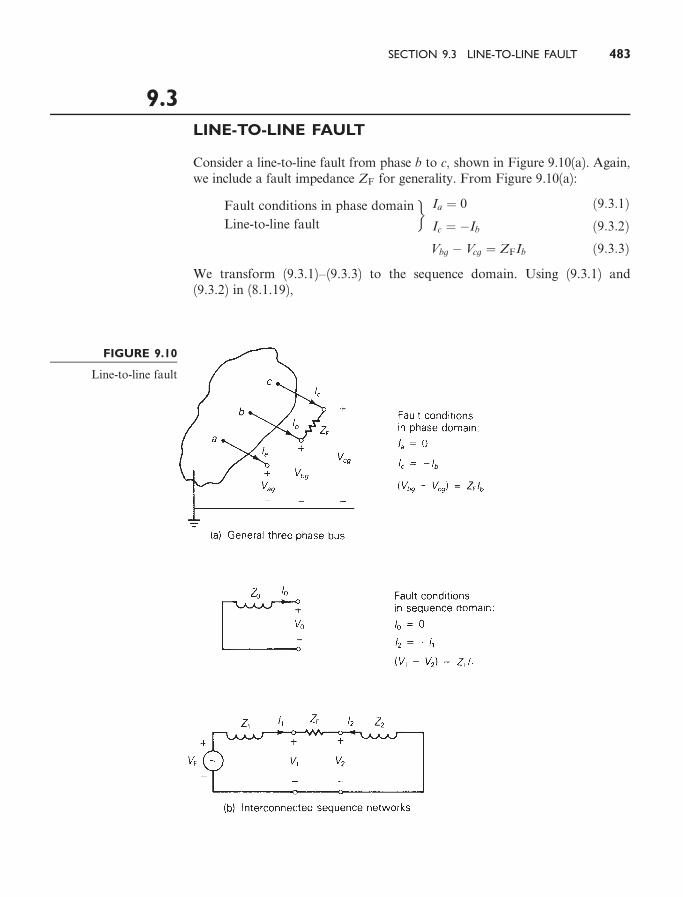
LINE-TO-LINE FAULT
Consider a line-to-line fault from phase b to c, shown in Figure 9.10(a). Again,we include a fault impedance ZF for generality. From Figure 9.10(a):
Fault conditions in phase domain
Line-to-line fault
�Ia ¼ 0 ð9:3:1ÞIc ¼ �Ib ð9:3:2ÞVbg � Vcg ¼ ZFIb ð9:3:3Þ
We transform (9.3.1)–(9.3.3) to the sequence domain. Using (9.3.1) and(9.3.2) in (8.1.19),
FIGURE 9.10
Line-to-line fault
SECTION 9.3 LINE-TO-LINE FAULT 483
264 I0
I1
I2
375¼ 1
3
264 1 1 1
1 a a2
1 a2 a
375264 0
Ib
�Ib
375¼
264 0
13 ða� a2ÞIb
13 ða2 � aÞIb
375 ð9:3:4Þ
Using (8.1.4), (8.1.5), and (8.1.21) in (9.3.3),
ðV0 þ a2V1 þ aV2Þ � ðV0 þ aV1 þ a2V2Þ ¼ ZFðI0 þ a2I1 þ aI2Þ ð9:3:5Þ
Noting from (9.3.4) that I0 ¼ 0 and I2 ¼ �I1, (9.3.5) simplifies to
ða2 � aÞV1 � ða2 � aÞV2 ¼ ZFða2 � aÞI1
or
V1 � V2 ¼ ZFI1 ð9:3:6Þ
Therefore, from (9.3.4) and (9.3.6):
Fault conditions in sequence domain
Line-to-line fault
�I0 ¼ 0 ð9:3:7Þ
I2 ¼ �I1 ð9:3:8Þ
V1 � V2 ¼ ZFI1 ð9:3:9Þ
Equations (9.3.7)–(9.3.9) are satisfied by connecting the positive- andnegative-sequence networks in parallel at the fault terminals through the faultimpedance ZF, as shown in Figure 9.10(b). From this figure, the fault cur-rents are:
I1 ¼ �I2 ¼VF
ðZ1 þ Z2 þ ZFÞI0 ¼ 0 ð9:3:10Þ
Transforming (9.3.10) to the phase domain and using the identity ða2 � aÞ ¼� j
ffiffiffi3p
, the fault current in phase b is
Ib ¼ I0 þ a2I1 þ aI2 ¼ ða2 � aÞI1
¼ � jffiffiffi3p
I1 ¼� j
ffiffiffi3p
VF
ðZ1 þ Z2 þ ZFÞð9:3:11Þ
Note also from (8.1.20) and (8.1.22) that
Ia ¼ I0 þ I1 þ I2 ¼ 0 ð9:3:12Þ
and
Ic ¼ I0 þ aI1 þ a2I2 ¼ ða� a2ÞI1 ¼ �Ib ð9:3:13Þ
which verify the fault conditions given by (9.3.1) and (9.3.2). The sequencecomponents of the line-to-ground voltages at the fault are given by (9.1.1).
EXAMPLE 9.4 Line-to-line short-circuit calculations using sequence networks
Calculate the subtransient fault current in per-unit and in kA for a boltedline-to-line fault from phase b to c at bus 2 in Example 9.1.
484 CHAPTER 9 UNSYMMETRICAL FAULTS

SOLUTION The positive- and negative-sequence networks in Figure 9.5 areconnected in parallel at the fault terminals, as shown in Figure 9.11. From(9.3.10) with ZF ¼ 0, the sequence fault currents are
I1 ¼ �I2 ¼1:05 0�
jð0:13893þ 0:14562Þ ¼ 3:690 �90�
I0 ¼ 0
From (9.3.11), the subtransient fault current in phase b is
I 00b ¼ ð� jffiffiffi3pÞð3:690 �90�Þ ¼ �6:391 ¼ 6:391 180� per unit
Using 4.1837 kA as the base current at bus 2,
I 00b ¼ ð6:391 180�Þð4:1837Þ ¼ 26:74 180� kA
Also, from (9.3.12) and (9.3.13),
I 00a ¼ 0 I 00c ¼ 26:74 0� kA
The line-to-line fault results for this example can be shown in Power-World Simulator by repeating the Example 9.3 procedure, with the exceptionthat the Fault Type field value should be ‘‘Line-to-Line.’’ 9
9.4
DOUBLE LINE-TO-GROUND FAULT
A double line-to-ground fault from phase b to phase c through fault imped-ance ZF to ground is shown in Figure 9.12(a). From this figure:
Fault conditions in the phase domain
Double line-to-ground fault
�Ia ¼ 0 ð9:4:1Þ
Vcg ¼ Vbg ð9:4:2Þ
Vbg ¼ ZFðIb þ IcÞ ð9:4:3Þ
Transforming (9.4.1) to the sequence domain via (8.1.20),
I0 þ I1 þ I2 ¼ 0 ð9:4:4Þ
Also, using (8.1.4) and (8.1.5) in (9.4.2),
ðV0 þ aV1 þ a2V2Þ ¼ ðV0 þ a2V1 þ aV2Þ
FIGURE 9.11
Example 9.4: Line-to-line fault at bus 2
SECTION 9.4 DOUBLE LINE-TO-GROUND FAULT 485

Simplifying:
ða2 � aÞV2 ¼ ða2 � aÞV1
or
V2 ¼ V1 ð9:4:5Þ
Now, using (8.1.4), (8.1.21), and (8.1.22) in (9.4.3),
ðV0 þ a2V1 þ aV2Þ ¼ ZFðI0 þ a2I1 þ aI2 þ I0 þ aI1 þ a2I2Þ ð9:4:6Þ
Using (9.4.5) and the identity a2 þ a ¼ �1 in (9.4.6),
ðV0 � V1Þ ¼ ZFð2I0 � I1 � I2Þ ð9:4:7Þ
From (9.4.4), I0 ¼ �ðI1 þ I2Þ; therefore, (9.4.7) becomes
V0 � V1 ¼ ð3ZFÞI0 ð9:4:8Þ
From (9.4.4), (9.4.5), and (9.4.8), we summarize:
Fault conditions in the sequence domain
Double line-to-ground fault
�I0 þ I1 þ I2 ¼ 0 ð9:4:9Þ
V2 ¼ V1 ð9:4:10Þ
V0�V1 ¼ ð3ZFÞI0 ð9:4:11Þ
FIGURE 9.12
Double line-to-groundfault
486 CHAPTER 9 UNSYMMETRICAL FAULTS

Equations (9.4.9)–(9.4.11) are satisfied by connecting the zero-, positive-,and negative-sequence networks in parallel at the fault terminal; addi-tionally, ð3ZFÞ is included in series with the zero-sequence network. Thisconnection is shown in Figure 9.12(b). From this figure the positive-sequencefault current is
I1 ¼VF
Z1 þ ½Z2EðZ0 þ 3ZFÞ�¼ VF
Z1 þZ2ðZ0 þ 3ZFÞZ2 þ Z0 þ 3ZF
� � ð9:4:12Þ
Using current division in Figure 9.12(b), the negative- and zero-sequencefault currents are
I2 ¼ ð�I1ÞZ0 þ 3ZF
Z0 þ 3ZF þ Z2
� �ð9:4:13Þ
I0 ¼ ð�I1ÞZ2
Z0 þ 3ZF þ Z2
� �ð9:4:14Þ
These sequence fault currents can be transformed to the phase domain via(8.1.16). Also, the sequence components of the line-to-ground voltages at thefault are given by (9.1.1).
EXAMPLE 9.5 Double line-to-ground short-circuit calculations using sequence
networks
Calculate (a) the subtransient fault current in each phase, (b) neutral faultcurrent, and (c) contributions to the fault current from the motor and fromthe transmission line, for a bolted double line-to-ground fault from phase b
to c to ground at bus 2 in Example 9.1. Neglect the D–Y transformer phaseshifts.
SOLUTION
a. The zero-, positive-, and negative-sequence networks in Figure 9.5 areconnected in parallel at the fault terminals in Figure 9.13. From (9.4.12)with ZF ¼ 0,
FIGURE 9.13
Example 9.5: Doubleline-to-ground fault at
bus 2
SECTION 9.4 DOUBLE LINE-TO-GROUND FAULT 487

I1 ¼1:05 0�
j 0:13893þ ð0:14562Þð0:25Þ0:14562þ 0:25
� � ¼ 1:05 0�
j0:23095
¼ � j4:5464 per unit
From (9.4.13) and (9.4.14),
I2 ¼ ðþ j4:5464Þ 0:25
0:25þ 0:14562
� �¼ j2:8730 per unit
I0 ¼ ðþ j4:5464Þ 0:14562
0:25þ 0:14562
� �¼ j1:6734 per unit
Transforming to the phase domain, the subtransient fault currents are:264 I 00a
I 00bI 00c
375¼
264 1 1 1
1 a2 a
1 a a2
375264þ j1:6734
� j4:5464
þ j2:8730
375¼
264 0
6:8983 158:66�
6:8983 21:34�
375 per unit
Using the base current of 4.1837 kA at bus 2,264 I 00a
I 00bI 00c
375¼
264 0
6:8983 158:66�
6:8983 21:34�
375ð4:1837Þ ¼
264 0
28:86 158:66�
28:86 21:34�
375 kA
b. The neutral fault current is
In ¼ ðI 00b þ I 00c Þ ¼ 3I0 ¼ j5:0202 per unit
¼ ð j5:0202Þð4:1837Þ ¼ 21:00 90� kA
c. Neglecting D–Y transformer phase shifts, the contributions to the faultcurrent from the motor and transmission line can be obtained fromFigure 9.4. From the zero-sequence network, Figure 9.4(a), the contribu-tion to the zero-sequence fault current from the line is zero, due to thetransformer connection. That is,
Iline 0 ¼ 0
Imotor 0 ¼ I0 ¼ j1:6734 per unit
From the positive-sequence network, Figure 9.4(b), the positive ter-minals of the internal machine voltages can be connected, since E 00g ¼ E 00m.Then, by current division,
Iline 1 ¼X 00m
X 00m þ ðX 00g þXT1 þXline 1 þXT2ÞI1
¼ 0:20
0:20þ ð0:455Þ ð� j4:5464Þ ¼ � j1:3882 per unit
Imotor 1 ¼0:455
0:20þ 0:455ð� j4:5464Þ ¼ � j3:1582 per unit
488 CHAPTER 9 UNSYMMETRICAL FAULTS

From the negative-sequence network, Figure 9.4(c), using currentdivision,
Iline 2 ¼0:21
0:21þ 0:475ð j2:8730Þ ¼ j0:8808 per unit
Imotor 2 ¼0:475
0:21þ 0:475ð j2:8730Þ ¼ j1:9922 per unit
Transforming to the phase domain with base currents of 0.41837 kA forthe line and 4.1837 kA for the motor,2
64 I 00line a
I 00line b
I 00line c
375¼
264 1 1 1
1 a2 a
1 a a2
375264 0
� j1:3882
j0:8808
375
¼
264 0:5074 �90�
1:9813 172:643�
1:9813 7:357�
375 per unit
¼
264 0:2123 �90�
0:8289 172:643�
0:8289 7:357�
375 kA
264 I 00motor a
I 00motor b
I 00motor c
375¼
264 1 1 1
1 a2 a
1 a a2
375264 j1:6734
� j3:1582
j1:9922
375
¼
264 0:5074 90�
4:9986 153:17�
4:9986 26:83�
375 per unit
¼
264 2:123 90�
20:91 153:17�
20:91 26:83�
375 kA
The double line-to-line fault results for this example can be shownin PowerWorld Simulator by repeating the Example 9.3 procedure, withthe exception that the Fault Type field value should be ‘‘Double Line-to-Ground.’’ 9
EXAMPLE 9.6 Effect of D–Y transformer phase shift on fault currents
Rework Example 9.5, with the D–Y transformer phase shifts included.Assume American standard phase shift.
SOLUTION The sequence networks of Figure 9.4 are redrawn in Figure 9.14with ideal phase-shifting transformers representing D–Y phase shifts. In
SECTION 9.4 DOUBLE LINE-TO-GROUND FAULT 489

accordance with the American standard, positive-sequence quantities on thehigh-voltage side of the transformers lead their corresponding quantities onthe low-voltage side by 30�. Also, the negative-sequence phase shifts are thereverse of the positive-sequence phase shifts.
a. Recall from Section 3.1 and (3.1.26) that per-unit impedance is un-changed when it is referred from one side of an ideal phase-shifting trans-former to the other. Accordingly, the Thevenin equivalents of thesequence networks in Figure 9.14, as viewed from fault bus 2, are the sameas those given in Figure 9.5. Therefore, the sequence components as wellas the phase components of the fault currents are the same as those givenin Example 9.5(a).
FIGURE 9.14 Sequence networks for Example 9.6
490 CHAPTER 9 UNSYMMETRICAL FAULTS

b. The neutral fault current is the same as that given in Example 9.5(b).
c. The zero-sequence network, Figure 9.14(a), is the same as that given inFigure 9.4(a). Therefore, the contributions to the zero-sequence fault cur-rent from the line and motor are the same as those given in Example9.5(c).
Iline 0 ¼ 0 Imotor 0 ¼ I0 ¼ j1:6734 per unit
The contribution to the positive-sequence fault current from the linein Figure 9.13(b) leads that in Figure 9.4(b) by 30�. That is,
Iline 1 ¼ ð� j1:3882Þð1 30�Þ ¼ 1:3882 �60� per unit
Imotor 1 ¼ � j3:1582 per unit
Similarly, the contribution to the negative-sequence fault currentfrom the line in Figure 9.14(c) lags that in Figure 9.4(c) by 30�. That is,
Iline 2 ¼ ð j0:8808Þð1 �30�Þ ¼ 0:8808 60� per unit
Imotor 2 ¼ j1:9922 per unit
Thus, the sequence currents as well as the phase currents from the motorare the same as those given in Example 9.5(c). Also, the sequence currentsfrom the line have the same magnitudes as those given in Example 9.5(c),but the positive- and negative-sequence line currents are shifted by þ30�
and �30�, respectively. Transforming the line currents to the phasedomain:2
64 I 00line a
I 00line b
I 00line c
375¼
264 1 1 1
1 a2 a
1 a a2
375264 0
1:3882 �60�
0:8808 60�
375
¼
264 1:2166=�21:17�
2:2690 180�
1:2166 21:17�
375 per unit
¼
264 0:5090 �21:17�
0:9492 180�
0:5090 21:17�
375 kA
In conclusion, D–Y transformer phase shifts have no e¤ect on the faultcurrents and no e¤ect on the contribution to the fault currents on the faultside of the D–Y transformers. However, on the other side of the D–Y trans-formers, the positive- and negative-sequence components of the contributionsto the fault currents are shifted by G30�, which a¤ects both the magnitudeas well as the angle of the phase components of these fault contributions forunsymmetrical faults. 9
SECTION 9.4 DOUBLE LINE-TO-GROUND FAULT 491

Figure 9.15 summarizes the sequence network connections for boththe balanced three-phase fault and the unsymmetrical faults that we haveconsidered. Sequence network connections for two additional faults, one-conductor-open and two-conductors-open, are also shown in Figure 9.15 andare left as an exercise for you to verify (see Problems 9.26 and 9.27).
9.5
SEQUENCE BUS IMPEDANCE MATRICES
We use the positive-sequence bus impedance matrix in Section 7.4 for calcu-lating currents and voltages during balanced three-phase faults. This methodis extended here to unsymmetrical faults by representing each sequence net-work as a bus impedance equivalent circuit (or as a rake equivalent). A bus
FIGURE 9.15 Summary of faults
492 CHAPTER 9 UNSYMMETRICAL FAULTS
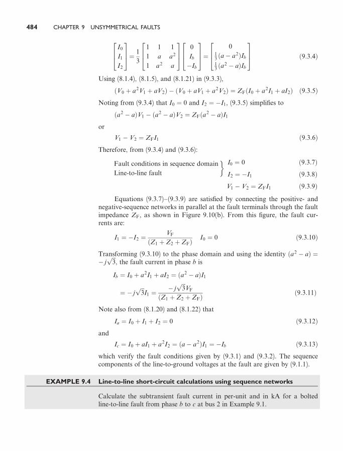
impedance matrix can be computed for each sequence network by invertingthe corresponding bus admittance network. For simplicity, resistances, shuntadmittances, nonrotating impedance loads, and prefault load currents areneglected.
Figure 9.16 shows the connection of sequence rake equivalents for bothsymmetrical and unsymmetrical faults at bus n of an N-bus three-phasepower system. Each bus impedance element has an additional subscript, 0, 1,or 2, that identifies the sequence rake equivalent in which it is located.Mutual impedances are not shown in the figure. The prefault voltage VF is
FIGURE 9.16 Connection of rake equivalent sequence networks for three-phase system faults(mutual impedances not shown)
SECTION 9.5 SEQUENCE BUS IMPEDANCE MATRICES 493

included in the positive-sequence rake equivalent. From the figure the se-quence components of the fault current for each type of fault at bus n are asfollows:
Balanced three-phase fault:
In�1 ¼VF
Znn�1ð9:5:1Þ
In�0 ¼ In�2 ¼ 0 ð9:5:2Þ
Single line-to-ground fault (phase a to ground):
In�0 ¼ In�1 ¼ In�2 ¼VF
Znn�0 þ Znn�1 þ Znn�2 þ 3ZFð9:5:3Þ
Line-to-line fault (phase b to c):
In�1 ¼ �In�2 ¼VF
Znn�1 þ Znn�2 þ ZFð9:5:4Þ
In�0 ¼ 0 ð9:5:5Þ
Double line-to-ground fault (phase b to c to ground):
In�1 ¼VF
Znn�1 þZnn�2ðZnn�0 þ 3ZFÞZnn�2 þ Znn�0 þ 3ZF
� � ð9:5:6Þ
In�2 ¼ ð�In�1ÞZnn�0 þ 3ZF
Znn�0 þ 3ZF þ Znn�2
� �ð9:5:7Þ
In�0 ¼ ð�In�1ÞZnn�2
Znn�0 þ 3ZF þ Znn�2
� �ð9:5:8Þ
Also from Figure 9.16, the sequence components of the line-to-ground volt-ages at any bus k during a fault at bus n are:2
64Vk�0
Vk�1
Vk�2
375¼
264 0
VF
0
375�
264Zkn�0 0 0
0 Zkn�1 0
0 0 Zkn�2
375264 In�0
In�1
In�2
375 ð9:5:9Þ
If bus k is on the unfaulted side of a D–Y transformer, then the phase anglesof Vk�1 and Vk�2 in (9.5.9) are modified to account for D–Y phase shifts.Also, the above sequence fault currents and sequence voltages can be trans-formed to the phase domain via (8.1.16) and (8.1.9).
EXAMPLE 9.7 Single line-to-ground short-circuit calculations using
Zbus 0, Zbus 1, and Zbus 2
Faults at buses 1 and 2 for the three-phase power system given in Example 9.1are of interest. The prefault voltage is 1.05 per unit. Prefault load current is
494 CHAPTER 9 UNSYMMETRICAL FAULTS

neglected. (a) Determine the per-unit zero-, positive-, and negative-sequencebus impedance matrices. Find the subtransient fault current in per-unit for abolted single line-to-ground fault current from phase a to ground (b) at bus 1and (c) at bus 2. Find the per-unit line-to-ground voltages at (d) bus 1 and (e)bus 2 during the single line-to-ground fault at bus 1.
SOLUTION
a. Referring to Figure 9.4(a), the zero-sequence bus admittance matrix is
Ybus 0 ¼ � j20 0
0 4
" #per unit
Inverting Ybus 0,
Zbus 0 ¼ j0:05 0
0 0:25
" #per unit
Note that the transformer leakage reactances and the zero-sequencetransmission-line reactance in Figure 9.4(a) have no e¤ect on Zbus 0. Thetransformer D connections block the flow of zero-sequence current fromthe transformers to bus 1 and 2.
The positive-sequence bus admittance matrix, from Figure 9.4(b), is
Ybus 1 ¼ � j9:9454 �3:2787
�3:2787 8:2787
" #per unit
Inverting Ybus 1,
Zbus 1 ¼ j0:11565 0:04580
0:04580 0:13893
" #per unit
Similarly, from Figure 9.4(c)
Ybus 2 ¼ � j9:1611 �3:2787
�3:2787 8:0406
" #
Inverting Ybus 2,
Zbus 2 ¼ j0:12781 0:05212
0:05212 0:14562
" #per unit
b. From (9.5.3), with n ¼ 1 and ZF ¼ 0, the sequence fault currents are
I1�0 ¼ I1�1 ¼ I1�2 ¼VF
Z11�0 þ Z11�1 þ Z11�2
¼ 1:05 0�
jð0:05þ 0:11565þ 0:12781Þ ¼1:05
j0:29346¼ � j3:578 per unit
SECTION 9.5 SEQUENCE BUS IMPEDANCE MATRICES 495

The subtransient fault currents at bus 1 are, from (8.1.16),
264 I 001a
I 001b
I 001c
375¼
264 1 1 1
1 a2 a
1 a a2
375264� j3:578
� j3:578
� j3:578
375¼
264� j10:73
0
0
375 per unit
c. Again from (9.5.3), with n ¼ 2 and ZF ¼ 0,
I2�0 ¼ I2�1 ¼ I2�2 ¼VF
Z22�0 þ Z22�1 þ Z22�2
¼ 1:05 0�
jð0:25þ 0:13893þ 0:14562Þ ¼1:05
j0:53455
¼ � j1:96427 per unit
and
264 I 002a
I 002b
I 002c
375¼
264 1 1 1
1 a2 a
1 a a2
375264� j1:96427
� j1:96427
� j1:96427
375¼
264� j5:8928
0
0
375 per unit
This is the same result as obtained in Example 9.3.
d. The sequence components of the line-to-ground voltages at bus 1 duringthe fault at bus 1 are, from (9.5.9), with k ¼ 1 and n ¼ 1,
264V1�0
V1�1
V1�2
375¼
264 0
1:05 0�
0
375�264 j0:05 0 0
0 j0:11565 0
0 0 j0:12781
375264� j3:578
� j3:578
� j3:578
375
¼
264�0:1789
0:6362
�0:4573
375 per unit
and the line-to-ground voltages at bus 1 during the fault at bus 1 are
264V1�ag
V1�bg
V1�cg
375¼
264 1 1 1
1 a2 a
1 a a2
375264�0:1789
þ0:6362
�0:4573
375
¼
264 0
0:9843 254:2�
0:9843 105:8�
375 per unit
496 CHAPTER 9 UNSYMMETRICAL FAULTS
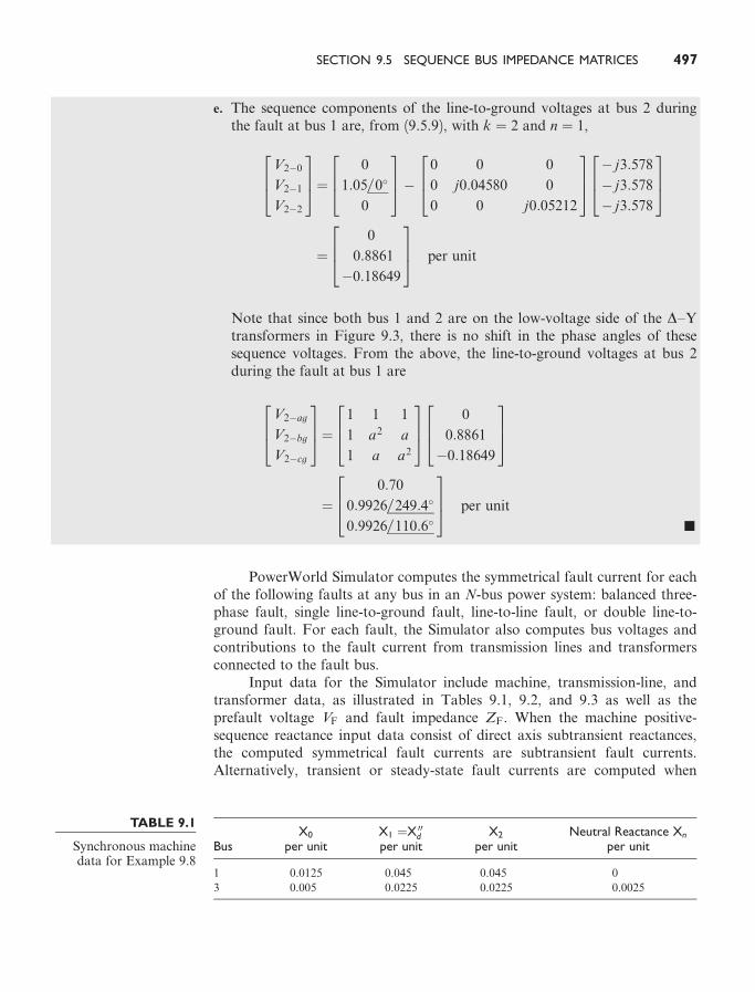
e. The sequence components of the line-to-ground voltages at bus 2 duringthe fault at bus 1 are, from (9.5.9), with k ¼ 2 and n ¼ 1,
264V2�0
V2�1
V2�2
375¼
264 0
1:05 0�
0
375�
264 0 0 0
0 j0:04580 0
0 0 j0:05212
375264� j3:578
� j3:578
� j3:578
375
¼
264 0
0:8861
�0:18649
375 per unit
Note that since both bus 1 and 2 are on the low-voltage side of the D–Ytransformers in Figure 9.3, there is no shift in the phase angles of thesesequence voltages. From the above, the line-to-ground voltages at bus 2during the fault at bus 1 are
264V2�ag
V2�bg
V2�cg
375¼
264 1 1 1
1 a2 a
1 a a2
375264 0
0:8861
�0:18649
375
¼
264 0:70
0:9926 249:4�
0:9926 110:6�
375 per unit
9
PowerWorld Simulator computes the symmetrical fault current for eachof the following faults at any bus in an N-bus power system: balanced three-phase fault, single line-to-ground fault, line-to-line fault, or double line-to-ground fault. For each fault, the Simulator also computes bus voltages andcontributions to the fault current from transmission lines and transformersconnected to the fault bus.
Input data for the Simulator include machine, transmission-line, andtransformer data, as illustrated in Tables 9.1, 9.2, and 9.3 as well as theprefault voltage VF and fault impedance ZF. When the machine positive-sequence reactance input data consist of direct axis subtransient reactances,the computed symmetrical fault currents are subtransient fault currents.Alternatively, transient or steady-state fault currents are computed when
TABLE 9.1
Synchronous machinedata for Example 9.8
BusX0
per unitX1 ¼X 00dper unit
X2
per unitNeutral Reactance Xn
per unit
1 0.0125 0.045 0.045 0
3 0.005 0.0225 0.0225 0.0025
SECTION 9.5 SEQUENCE BUS IMPEDANCE MATRICES 497

these input data consist of direct axis transient or synchronous reactances.Transmission-line positive- and zero-sequence series reactances are those ofthe equivalent p circuits for long lines or of the nominal p circuit for mediumor short lines. Also, recall that the negative-sequence transmission-linereactance equals the positive-sequence transmission-line reactance. All ma-chine, line, and transformer reactances are given in per-unit on a commonMVA base. Prefault load currents are neglected.
The Simulator computes (but does not show) the zero-, positive-, andnegative-sequence bus impedance matrices Zbus 0;Zbus 1, and Zbus 2, byinverting the corresponding bus admittance matrices.
After Zbus 0;Zbus 1, and Zbus 2 are computed, (9.5.1)–(9.5.9) are used tocompute the sequence fault currents and the sequence voltages at each busduring a fault at bus 1 for the fault type selected by the program user (for ex-ample, three-phase fault, or single line-to-ground fault, and so on). Con-tributions to the sequence fault currents from each line or transformer branchconnected to the fault bus are computed by dividing the sequence voltageacross the branch by the branch sequence impedance. The phase angles ofpositive- and negative-sequence voltages are also modified to account forD–Y transformer phase shifts. The sequence currents and sequence voltagesare then transformed to the phase domain via (8.1.16) and (8.1.9). All thesecomputations are then repeated for a fault at bus 2, then bus 3, and so on tobus N.
Output data for the fault type and fault impedance selected by the userconsist of the fault current in each phase, contributions to the fault currentfrom each branch connected to the fault bus for each phase, and the line-to-ground voltages at each bus—for a fault at bus 1, then bus 2, and so on tobus N.
TABLE 9.2
Line data forExample 9.8
Bus-to-BusX0
per unitX1
per unit
2–4 0.3 0.1
2–5 0.15 0.05
4–5 0.075 0.025
TABLE 9.3
Transformer data forExample 9.8
Low-Voltage(connection)
bus
High-Voltage(connection)
busLeakage Reactance
per unitNeutral Reactance
per unit
1 (D) 5 (Y) 0.02 0
3 (D) 4 (Y) 0.01 0
Sbase ¼ 100 MVA
Vbase ¼ 15 kV at buses 1; 3345 kV at buses 2; 4; 5
�
498 CHAPTER 9 UNSYMMETRICAL FAULTS

EXAMPLE 9.8 PowerWorld Simulator
Consider the five-bus power system whose single-line diagram is shown inFigure 6.2. Machine, line, and transformer data are given in Tables 9.1, 9.2,and 9.3. Note that the neutrals of both transformers and generator 1 aresolidly grounded, as indicated by a neutral reactance of zero for these equip-ments. However, a neutral reactance ¼ 0:0025 per unit is connected to thegenerator 2 neutral. The prefault voltage is 1.05 per unit. Using PowerWorldSimulator, determine the fault currents and voltages for a bolted single line-to-ground fault at bus 1, then bus 2, and so on to bus 5.
SOLUTION Open PowerWorld Simulator case Example 9.8 to see thisexample. Tables 9.4 and 9.5 summarize the PowerWorld Simulator results foreach of the faults. Note that these fault currents are subtransient currents,since the machine positive-sequence reactance input consists of direct axissubtransient reactances.
TABLE 9.4
Fault currents forExample 9.8
Contributions to Fault Current
Phase ACurrentPhase B Phase C
FaultBus
SingleLine-to-GroundFault Current
(Phase A)per unit/degrees
GENLINEOR
TRSFBus-to-
Bus per unit/degrees
1 46.02/�90.00 G1 GRND–1 34.41/
�90.00
5.804/
�90.00
5.804/
�90.00
T1 5–1 11.61/
�90.00
5.804/
90.00
5.804/
90.00
2 14.14/�90.00 L1 4–2 5.151/
�90.00
0.1124/
90.00
0.1124/
90.00
L2 5–2 8.984/
�90.00
0.1124/
�90.00
0.1124/
�90.00
3 64.30/�90.00 G2 GRND–3 56.19/
�90.00
4.055/
�90.00
4.055/
�90.00
T2 4–3 8.110/
�90.00
4.055/
90.00
4.055/
90.00
4 56.07/�90.00 L1 2–4 1.742/
�90.00
0.4464/
90.00
0.4464/
90.00
L3 5–4 10.46/
�90.00
2.679/
90.00
2.679/
90.00
T2 3–4 43.88/
�90.00
3.125/
�90.00
3.125/
�90.00
5 42.16/�90.00 L2 2–5 2.621/
�90.00
0.6716/
90.00
0.6716/
90.00
L3 4–5 15.72/
�90.00
4.029/
90.00
4.029/
90.00
T1 1–5 23.82/
�90.00
4.700/
�90.00
4.700/
�90.00
SECTION 9.5 SEQUENCE BUS IMPEDANCE MATRICES 499

M U L T I P L E C H O I C E Q U E S T I O N S
SECTION 9.1
9.1 For power-system fault studies, it is assumed that the system is operating under bal-anced steady-state conditions prior to the fault, and sequence networks are uncoupledbefore the fault occurs.(a) True (b) False
9.2 The first step in power-system fault calculations is to develop sequence networks basedon the single-line diagram of the system, and then reduce them to their Theveninequivalents, as viewed from the fault location.(a) True (b) False
9.3 When calculating symmetrical three-phase fault currents, only _______ sequence networkneeds to be considered. Fill in the Blank.
9.4 In order of frequency of occurance of short-circuit faults in three-phase power sys-tems, list those: ________, ________, ________, ________. Fill in the Blanks.
TABLE 9.5
Bus voltages forExample 9.8
Vprefault ¼ 1:05 e0 Bus Voltages during Fault
Fault Bus Bus Phase A Phase B Phase C
1 1 0.0000e0.00 0.9537e�107.55 0.9537e107.55
2 0.5069e0.00 0.9440e�105.57 0.9440e105.57
3 0.7888e0.00 0.9912e�113.45 0.9912e113.45
4 0.6727e0.00 0.9695e�110.30 0.9695e110.30
5 0.4239e0.00 0.9337e�103.12 0.9337e103.12
2 1 0.8832e0.00 1.0109e�115.90 1.0109e115.90
2 0.0000e0.00 1.1915e�130.26 1.1915e130.26
3 0.9214e0.00 1.0194e�116.87 1.0194e116.87
4 0.8435e0.00 1.0158e�116.47 1.0158e116.47
5 0.7562e0.00 1.0179e�116.70 1.0179e116.70
3 1 0.6851e0.00 0.9717e�110.64 0.9717e110.64
2 0.4649e0.00 0.9386e�104.34 0.9386e104.34
3 0.0000e0.00 0.9942e�113.84 0.9942e113.84
4 0.3490e0.00 0.9259e�100.86 0.9259e100.86
5 0.5228e0.00 0.9462e�106.04 0.9462e106.04
4 1 0.5903e0.00 0.9560e�107.98 0.9560e107.98
2 0.2309e0.00 0.9401e�104.70 0.9401e104.70
3 0.4387e0.00 0.9354e�103.56 0.9354e103.56
4 0.0000e0.00 0.9432e�105.41 0.9432e105.41
5 0.3463e0.00 0.9386e�104.35 0.9386e104.35
5 1 0.4764e0.00 0.9400e�104.68 0.9400e104.68
2 0.1736e0.00 0.9651e�109.57 0.9651e109.57
3 0.7043e0.00 0.9751e�111.17 0.9751e111.17
4 0.5209e0.00 0.9592e�108.55 0.9592e108.55
5 0.0000e0.00 0.9681e�110.07 0.9681e110.07
9
500 CHAPTER 9 UNSYMMETRICAL FAULTS
9.5 For a bolted three-phase-to-ground fault, sequence-fault currents _________ are zero,sequence fault voltages are ________, and line-to-ground voltages are ________. Fillin the Blanks.
SECTION 9.2
9.6 For a single-line-to-ground fault with a fault-impedance ZF, the sequence networks areto be connected _________ at the fault terminals through the impedance ________; thesequence components of the fault currents are ___________. Fill in the Blanks.
SECTION 9.3
9.7 For a line-to-line fault with a fault impedance ZF, the positive-and negative-sequencenetworks are to be connected _____________ at the fault terminals through the im-pedance of 1/2/3 times ZF; the zero-sequence current is _________. Fill in the Blanks.
SECTION 9.4
9.8 For a double line-to-ground fault through a fault impedance ZF, the sequence networksare to be connected _____________, at the fault terminal; additionally, _________ isto be included in series with the zero-sequence network. Fill in the Blanks.
SECTION 9.5
9.9 The sequence bus-impedance matrices can also be used to calculate fault currents andvoltages for symmetrical as well as unsymmetrical faults by representing each se-quence network as a bus-impedance rake-equivalent circuit.(a) True (b) False
P R O B L E M S
SECTION 9.1
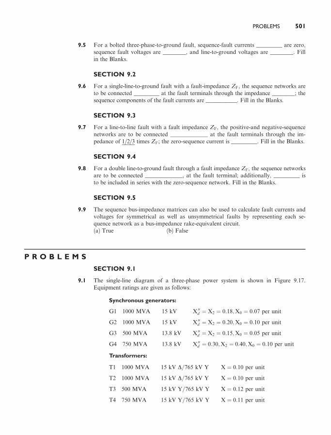
9.1 The single-line diagram of a three-phase power system is shown in Figure 9.17.Equipment ratings are given as follows:
Synchronous generators:
G1 1000 MVA 15 kV X 00d ¼ X2 ¼ 0:18;X0 ¼ 0:07 per unit
G2 1000 MVA 15 kV X 00d ¼ X2 ¼ 0:20;X0 ¼ 0:10 per unit
G3 500 MVA 13:8 kV X 00d ¼ X2 ¼ 0:15;X0 ¼ 0:05 per unit
G4 750 MVA 13:8 kV X 00d ¼ 0:30;X2 ¼ 0:40;X0 ¼ 0:10 per unit
Transformers:
T1 1000 MVA 15 kV D=765 kV Y X ¼ 0:10 per unit
T2 1000 MVA 15 kV D=765 kV Y X ¼ 0:10 per unit
T3 500 MVA 15 kV Y=765 kV Y X ¼ 0:12 per unit
T4 750 MVA 15 kV Y=765 kV Y X ¼ 0:11 per unit
PROBLEMS 501

Transmission lines:
1a2 765 kV X1 ¼ 50 W; X0 ¼ 150 W
1a3 765 kV X1 ¼ 40 W; X0 ¼ 100 W
2a3 765 kV X1 ¼ 40 W; X0 ¼ 100 W
The inductor connected to Generator 3 neutral has a reactance of 0.05 per unit usinggenerator 3 ratings as a base. Draw the zero-, positive-, and negative-sequence react-ance diagrams using a 1000-MVA, 765-kV base in the zone of line 1–2. Neglect theD–Y transformer phase shifts.
9.2 Faults at bus n in Problem 9.1 are of interest (the instructor selects n ¼ 1; 2, or 3).Determine the Thevenin equivalent of each sequence network as viewed from the faultbus. Prefault voltage is 1.0 per unit. Prefault load currents and D–Y transformer phaseshifts are neglected. (Hint: Use the Y–D conversion in Figure 2.27.)
9.3 Determine the subtransient fault current in per-unit and in kA during a bolted three-phase fault at the fault bus selected in Problem 9.2.
9.4 In Problem 9.1 and Figure 9.17, let 765 kV be replaced by 500 kV, keeping the rest ofthe data to be the same. Repeat (a) Problems 9.1, (b) 9.2, and (c) 9.3.
9.5 Equipment ratings for the four-bus power system shown in Figure 7.14 are given asfollows:
Generator G1: 500 MVA, 13.8 kV, X 00d ¼ X2 ¼ 0:20, X0 ¼ 0:10 per unit
Generator G2: 750 MVA, 18 kV, X 00d ¼ X2 ¼ 0:18, X0 ¼ 0:09 per unit
Generator G3: 1000 MVA, 20 kV, X 00d ¼ 0:17, X2 ¼ 0:20, X0 ¼ 0:09 per unit
Transformer T1: 500 MVA, 13.8 kV D/500 kV Y, X ¼ 0:12 per unit
Transformer T2: 750 MVA, 18 kV D/500 kV Y, X ¼ 0:10 per unit
Transformer T3: 1000 MVA, 20 kV D/500 kV Y, X ¼ 0:10 per unit
Each line: X1 ¼ 50 ohms, X0 ¼ 150 ohms
The inductor connected to generator G3 neutral has a reactance of 0.028 W. Draw thezero-, positive-, and negative-sequence reactance diagrams using a 1000-MVA, 20-kVbase in the zone of generator G3. Neglect D–Y transformer phase shifts.
9.6 Faults at bus n in Problem 9.5 are of interest (the instructor selects n ¼ 1; 2; 3, or 4).Determine the Thevenin equivalent of each sequence network as viewed from the fault
FIGURE 9.17
Problem 9.1
502 CHAPTER 9 UNSYMMETRICAL FAULTS

bus. Prefault voltage is 1.0 per unit. Prefault load currents and D–Y phase shifts areneglected.
9.7 Determine the subtransient fault current in per-unit and in kA during a bolted three-phase fault at the fault bus selected in Problem 9.6.
9.8 Equipment ratings for the five-bus power system shown in Figure 7.15 are given as follows:
Generator G1: 50 MVA, 12 kV, X 00d ¼ X2 ¼ 0:20, X0 ¼ 0:10 per unit
Generator G2: 100 MVA, 15 kV, X 00d ¼ 0:2, X2 ¼ 0:23, X0 ¼ 0:1 per unit
Transformer T1: 50 MVA, 10 kV Y/138 kV Y, X ¼ 0:10 per unit
Transformer T2: 100 MVA, 15 kV D/138 kV Y, X ¼ 0:10 per unit
Each 138-kV line: X1 ¼ 40 ohms, X0 ¼ 100 ohms
Draw the zero-, positive-, and negative-sequence reactance diagrams using a 100-MVA, 15-kV base in the zone of generator G2. Neglect D–Y transformer phase shifts.
9.9 Faults at bus n in Problem 9.8 are of interest (the instructor selects n ¼ 1, 2, 3, 4,or 5). Determine the Thevenin equivalent of each sequence network as viewed fromthe fault bus. Prefault voltage is 1.0 per unit. Prefault load currents and D–Y phaseshifts are neglected.
9.10 Determine the subtransient fault current in per-unit and in kA during a bolted three-phase fault at the fault bus selected in Problem 9.9.
9.11 Consider the system shown in Figure 9.18. (a) As viewed from the fault at F, deter-mine the Thevenin equivalent of each sequence network. Neglect D–Y phase shifts. (b)Compute the fault currents for a balanced three-phase fault at fault point F throughthree fault impedances ZFA ¼ ZFB ¼ ZFC ¼ j0:5 per unit. Equipment data in per-uniton the same base are given as follows:
Synchronous generators:
G1 X1 ¼ 0:2 X2 ¼ 0:12 X0 ¼ 0:06
G2 X1 ¼ 0:33 X2 ¼ 0:22 X0 ¼ 0:066
Transformers:
T1 X1 ¼ X2 ¼ X0 ¼ 0:2
T2 X1 ¼ X2 ¼ X0 ¼ 0:225
FIGURE 9.18
Problem 9.11
PROBLEMS 503

T3 X1 ¼ X2 ¼ X0 ¼ 0:27
T4 X1 ¼ X2 ¼ X0 ¼ 0:16
Transmission lines:
L1 X1 ¼ X2 ¼ 0:14 X0 ¼ 0:3
L1 X1 ¼ X2 ¼ 0:35 X0 ¼ 0:6
9.12 Equipment ratings and per-unit reactances for the system shown in Figure 9.19 aregiven as follows:
Synchronous generators:
G1 100 MVA 25 kV X1 ¼ X2 ¼ 0:2 X0 ¼ 0:05
G2 100 MVA 13:8 kV X1 ¼ X2 ¼ 0:2 X0 ¼ 0:05
Transformers:
T1 100 MVA 25=230 kV X1 ¼ X2 ¼ X0 ¼ 0:05
T2 100 MVA 13:8=230 kV X1 ¼ X2 ¼ X0 ¼ 0:05
Transmission lines:
TL12 100 MVA 230 kV X1 ¼ X2 ¼ 0:1 X0 ¼ 0:3
TL13 100 MVA 230 kV X1 ¼ X2 ¼ 0:1 X0 ¼ 0:3
TL23 100 MVA 230 kV X1 ¼ X2 ¼ 0:1 X0 ¼ 0:3
Using a 100-MVA, 230-kV base for the transmission lines, draw the per-unit sequencenetworks and reduce them to their Thevenin equivalents, ‘‘looking in’’ at bus 3. NeglectD–Y phase shifts. Compute the fault currents for a bolted three-phase fault at bus 3.
9.13 Consider the one-line diagram of a simple power system shown in Figure 9.20. Systemdata in per-unit on a 100-MVA base are given as follows:
Synchronous generators:
G1 100 MVA 20 kV X1 ¼ X2 ¼ 0:15 X0 ¼ 0:05
G2 100 MVA 20 kV X1 ¼ X2 ¼ 0:15 X0 ¼ 0:05
Transformers:
T1 100 MVA 20=220 kV X1 ¼ X2 ¼ X0 ¼ 0:1
T2 100 MVA 20=220 kV X1 ¼ X2 ¼ X0 ¼ 0:1
FIGURE 9.19
Problem 9.12
504 CHAPTER 9 UNSYMMETRICAL FAULTS

Transmission lines:
L12 100 MVA 220 kV X1 ¼ X2 ¼ 0:125 X0 ¼ 0:3
L13 100 MVA 220 kV X1 ¼ X2 ¼ 0:15 X0 ¼ 0:35
L23 100 MVA 220 kV X1 ¼ X2 ¼ 0:25 X0 ¼ 0:7125
The neutral of each generator is grounded through a current-limiting reactor of 0.08333per unit on a 100-MVA base. All transformer neutrals are solidly grounded. The gen-erators are operating no-load at their rated voltages and rated frequency with their EMFsin phase. Determine the fault current for a balanced three-phase fault at bus 3 through afault impedance ZF ¼ 0:1 per unit on a 100-MVA base. Neglect D–Y phase shifts.
SECTIONS 9.2–9.4
9.14 Determine the subtransient fault current in per-unit and in kA, as well as the per-unitline-to-ground voltages at the fault bus for a bolted single line-to-ground fault at thefault bus selected in Problem 9.2.
9.15 Repeat Problem 9.14 for a single line-to-ground arcing fault with arc impedanceZF ¼ 30þ j0 W.
9.16 Repeat Problem 9.14 for a bolted line-to-line fault.
9.17 Repeat Problem 9.14 for a bolted double line-to-ground fault.
9.18 Repeat Problems 9.1 and 9.14 including D–Y transformer phase shifts. AssumeAmerican standard phase shift. Also calculate the sequence components and phasecomponents of the contribution to the fault current from generator n (n ¼ 1; 2, or 3 asspecified by the instructor in Problem 9.2).
9.19 (a) Repeat Problem 9.14 for the case of Problem 9.4 (b).(b) Repeat Problem 9.19(a) for a single line-to-ground arcing fault with arc impedanceZF ¼ ð15þ j0Þ W:(c) Repeat Problem 9.19(a) for a bolted line-to-line fault.(d) Repeat Problem 9.19(a) for a bolted double line-to-ground fault.(e) Repeat Problems 9.4(a) and 9.19(a) including D–Y transformer phase shifts. As-sume American standard phase shift. Also calculate the sequence components andphase components of the contribution to the fault current from generator n (n ¼ 1; 2;or 3) as specified by the instructor in Problem 9.4(b).
FIGURE 9.20
Problem 9.13
PROBLEMS 505

9.20 A 500-MVA, 13.8-kV synchronous generator with X 00d ¼ X2 ¼ 0:20 and X0 ¼ 0:05 perunit is connected to a 500-MVA, 13.8-kV D/500-kV Y transformer with 0.10 per-unitleakage reactance. The generator and transformer neutrals are solidly grounded. Thegenerator is operated at no-load and rated voltage, and the high-voltage side of thetransformer is disconnected from the power system. Compare the subtransient faultcurrents for the following bolted faults at the transformer high-voltage terminals:three-phase fault, single line-to-ground fault, line-to-line fault, and double line-to-ground fault.
9.21 Determine the subtransient fault current in per-unit and in kA, as well as contribu-tions to the fault current from each line and transformer connected to the fault bus fora bolted single line-to-ground fault at the fault bus selected in Problem 9.6.
9.22 Repeat Problem 9.21 for a bolted line-to-line fault.
9.23 Repeat Problem 9.21 for a bolted double line-to-ground fault.
9.24 Determine the subtransient fault current in per-unit and in kA, as well as contributionsto the fault current from each line, transformer, and generator connected to the faultbus for a bolted single line-to-ground fault at the fault bus selected in Problem 9.9.
9.25 Repeat Problem 9.24 for a single line-to-ground arcing fault with arc impedanceZF ¼ 0:05þ j0 per unit.
9.26 Repeat Problem 9.24 for a bolted line-to-line fault.
9.27 Repeat Problem 9.24 for a bolted double line-to-ground fault.
9.28 As shown in Figure 9.21(a), two three-phase buses abc and a 0b 0c 0 are interconnectedby short circuits between phases b and b 0 and between c and c 0, with an open circuitbetween phases a and a 0. The fault conditions in the phase domain are Ia ¼ Ia 0 ¼ 0and Vbb 0 ¼ Vcc 0 ¼ 0. Determine the fault conditions in the sequence domain and verifythe interconnection of the sequence networks as shown in Figure 9.15 for this one-conductor-open fault.
9.29 Repeat Problem 9.28 for the two-conductors-open fault shown in Figure 9.21(b). Thefault conditions in the phase domain are
Ib ¼ Ib 0 ¼ Ic ¼ Ic 0 ¼ 0 and Vaa 0 ¼ 0
9.30 For the system of Problem 9.11, compute the fault current and voltages at the faultfor the following faults at point F: (a) a bolted single line-to-ground fault; (b) a line-to-line fault through a fault impedance ZF ¼ j0:05 per unit; (c) a double line-to-ground fault from phase B to C to ground, where phase B has a fault impedanceZF ¼ j0:05 per unit, phase C also has a fault impedance ZF ¼ j0:05 per unit, and thecommon line-to-ground fault impedance is ZG ¼ j0:033 per unit.
FIGURE 9.21
Problems 9.28 and 9.29:open conductor faults
506 CHAPTER 9 UNSYMMETRICAL FAULTS
9.31 For the system of Problem 9.12, compute the fault current and voltages at the faultfor the following faults at bus 3: (a) a bolted single line-to-ground fault, (b) a boltedline-to-line fault, (c) a bolted double line-to-ground fault. Also, for the single line-to-ground fault at bus 3, determine the currents and voltages at the terminals of gen-erators G1 and G2.
9.32 For the system of Problem 9.13, compute the fault current for the following faults atbus 3: (a) a single line-to-ground fault through a fault impedance ZF ¼ j0:1 per unit,(b) a line-to-line fault through a fault impedance ZF ¼ j0:1 per unit, (c) a double line-to-ground fault through a common fault impedance to ground ZF ¼ j0:1 per unit.
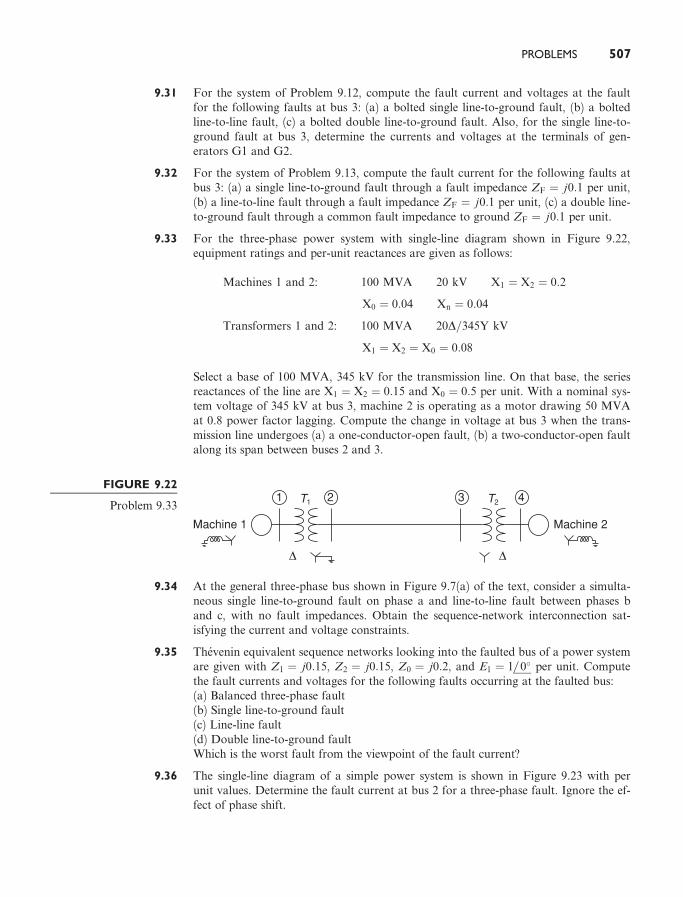
9.33 For the three-phase power system with single-line diagram shown in Figure 9.22,equipment ratings and per-unit reactances are given as follows:
Machines 1 and 2: 100 MVA 20 kV X1 ¼ X2 ¼ 0:2
X0 ¼ 0:04 Xn ¼ 0:04
Transformers 1 and 2: 100 MVA 20D=345Y kV
X1 ¼ X2 ¼ X0 ¼ 0:08
Select a base of 100 MVA, 345 kV for the transmission line. On that base, the seriesreactances of the line are X1 ¼ X2 ¼ 0:15 and X0 ¼ 0:5 per unit. With a nominal sys-tem voltage of 345 kV at bus 3, machine 2 is operating as a motor drawing 50 MVAat 0.8 power factor lagging. Compute the change in voltage at bus 3 when the trans-mission line undergoes (a) a one-conductor-open fault, (b) a two-conductor-open faultalong its span between buses 2 and 3.
9.34 At the general three-phase bus shown in Figure 9.7(a) of the text, consider a simulta-neous single line-to-ground fault on phase a and line-to-line fault between phases band c, with no fault impedances. Obtain the sequence-network interconnection sat-isfying the current and voltage constraints.
9.35 Thevenin equivalent sequence networks looking into the faulted bus of a power systemare given with Z1 ¼ j0:15, Z2 ¼ j0:15, Z0 ¼ j0:2, and E1 ¼ 1 0� per unit. Computethe fault currents and voltages for the following faults occurring at the faulted bus:(a) Balanced three-phase fault(b) Single line-to-ground fault(c) Line-line fault(d) Double line-to-ground faultWhich is the worst fault from the viewpoint of the fault current?
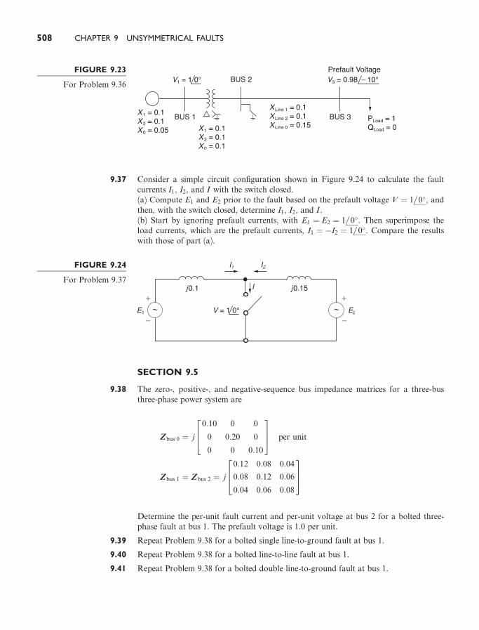
9.36 The single-line diagram of a simple power system is shown in Figure 9.23 with perunit values. Determine the fault current at bus 2 for a three-phase fault. Ignore the ef-fect of phase shift.
FIGURE 9.22
Problem 9.33
PROBLEMS 507
9.37 Consider a simple circuit configuration shown in Figure 9.24 to calculate the faultcurrents I1, I2, and I with the switch closed.(a) Compute E1 and E2 prior to the fault based on the prefault voltage V ¼ 1 0�, andthen, with the switch closed, determine I1, I2, and I .(b) Start by ignoring prefault currents, with E1 ¼ E2 ¼ 1 0�. Then superimpose theload currents, which are the prefault currents, I1 ¼ �I2 ¼ 1 0�. Compare the resultswith those of part (a).
SECTION 9.5
9.38 The zero-, positive-, and negative-sequence bus impedance matrices for a three-busthree-phase power system are
Zbus 0 ¼ j
264
0:10 0 0
0 0:20 0
0 0 0:10
375 per unit
Zbus 1 ¼ Zbus 2 ¼ j
264 0:12 0:08 0:04
0:08 0:12 0:06
0:04 0:06 0:08
375
Determine the per-unit fault current and per-unit voltage at bus 2 for a bolted three-phase fault at bus 1. The prefault voltage is 1.0 per unit.
9.39 Repeat Problem 9.38 for a bolted single line-to-ground fault at bus 1.
9.40 Repeat Problem 9.38 for a bolted line-to-line fault at bus 1.
9.41 Repeat Problem 9.38 for a bolted double line-to-ground fault at bus 1.
FIGURE 9.23
For Problem 9.36
FIGURE 9.24
For Problem 9.37
508 CHAPTER 9 UNSYMMETRICAL FAULTS

9.42 (a) Compute the 3� 3 per-unit zero-, positive-, and negative-sequence bus impedancematrices for the power system given in Problem 9.1. Use a base of 1000 MVA and765 kV in the zone of line 1–2.
9.42 (b) Using the bus impedance matrices determined in Problem 9.42, verify the fault cur-rents for the faults given in Problems 9.3, 9.14, 9.15, 9.16, and 9.17.
9.43 The zero-, positive-, and negative-sequence bus impedance matrices for a two-busthree-phase power system are
Zbus 0 ¼ j0:10 0
0 0:10
" #per unit
Zbus 1 ¼ Zbus 2 ¼ j0:20 0:10
0:10 0:30
" #per unit
Determine the per-unit fault current and per-unit voltage at bus 2 for a bolted three-phase fault at bus 1. The prefault voltage is 1.0 per unit.
9.44 Repeat Problem 9.43 for a bolted single line-to-ground fault at bus 1.
9.45 Repeat Problem 9.43 for a bolted line-to-line fault at bus 1.
9.46 Repeat Problem 9.43 for a bolted double line-to-ground fault at bus 1.
9.47 Compute the 3� 3 per-unit zero-, positive-, and negative-sequence bus impedancematrices for the power system given in Problem 4(a). Use a base of 1000 MVA and500 kV in the zone of line 1–2.
9.48 Using the bus impedance matrices determined in Problem 9.47, verify the fault cur-rents for the faults given in Problems 9.4(b), 9.4(c), 9.19 (a through d).
9.49 Compute the 4� 4 per-unit zero-, positive-, and negative-sequence bus impedancematrices for the power system given in Problem 9.5. Use a base of 1000 MVA and20 kV in the zone of generator G3.
9.50 Using the bus impedance matrices determined in Problem 9.42, verify the fault cur-rents for the faults given in Problems 9.7, 9.21, 9.22, and 9.23.
9.51 Compute the 5� 5 per-unit zero-, positive-, and negative-sequence bus impedancematrices for the power system given in Problem 9.8. Use a base of 100 MVA and15 kV in the zone of generator G2.
9.52 Using the bus impedance matrices determined in Problem 9.51, verify the fault cur-rents for the faults given in Problems 9.10, 9.24, 9.25, 9.26, and 9.27.
9.53 The positive-sequence impedance diagram of a five-bus network with all values in per-unit on a 100-MVA base is shown in Figure 9.25. The generators at buses 1 and 3are rated 270 and 225 MVA, respectively. Generator reactances include subtransientvalues plus reactances of the transformers connecting them to the buses. The turnsratios of the transformers are such that the voltage base in each generator circuit isequal to the voltage rating of the generator. (a) Develop the positive-sequence busadmittance matrix Ybus 1. (b) Using MATLAB or another computer program, invertYbus 1 to obtain Zbus 1. (c) Determine the subtransient current for a three-phase fault
PROBLEMS 509

at bus 4 and the contributions to the fault current from each line. Neglect prefaultcurrents and assume a prefault voltage of 1.0 per unit.
9.54 For the five-bus network shown in Figure 9.25, a bolted single-line-to-ground faultoccurs at the bus 2 end of the transmission line between buses 1 and 2. The faultcauses the circuit breaker at the bus 2 end of the line to open, but all other breakersremain closed. The fault is shown in Figure 9.26. Compute the subtransient fault cur-rent with the circuit breaker at the bus-2 end of the faulted line open. Neglect prefaultcurrent and assume a prefault voltage of 1.0 per unit.
9.55 A single-line diagram of a four-bus system is shown in Figure 9.27. Equipment ratingsand per-unit reactances are given as follows.
Machines 1 and 2: 100 MVA 20 kV X1 ¼ X2 ¼ 0:2
X0 ¼ 0:04 Xn ¼ 0:05
Transformers T1 and T2: 100 MVA 20D=345Y kV
X1 ¼ X2 ¼ X0 ¼ 0:08
On a base of 100 MVA and 345 kV in the zone of the transmission line, the series re-actances of the transmission line are X1 ¼ X2 ¼ 0:15 and X0 ¼ 0:5 per unit. (a) Draw
FIGURE 9.25
Problems 9.53 and 9.54
FIGURE 9.26
Problem 9.54
510 CHAPTER 9 UNSYMMETRICAL FAULTS
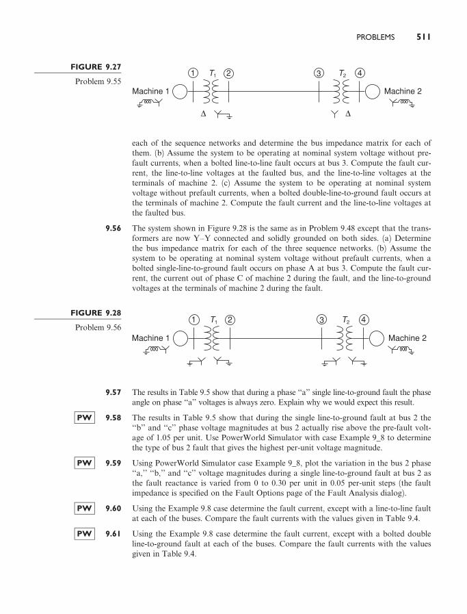
each of the sequence networks and determine the bus impedance matrix for each ofthem. (b) Assume the system to be operating at nominal system voltage without pre-fault currents, when a bolted line-to-line fault occurs at bus 3. Compute the fault cur-rent, the line-to-line voltages at the faulted bus, and the line-to-line voltages at theterminals of machine 2. (c) Assume the system to be operating at nominal systemvoltage without prefault currents, when a bolted double-line-to-ground fault occurs atthe terminals of machine 2. Compute the fault current and the line-to-line voltages atthe faulted bus.
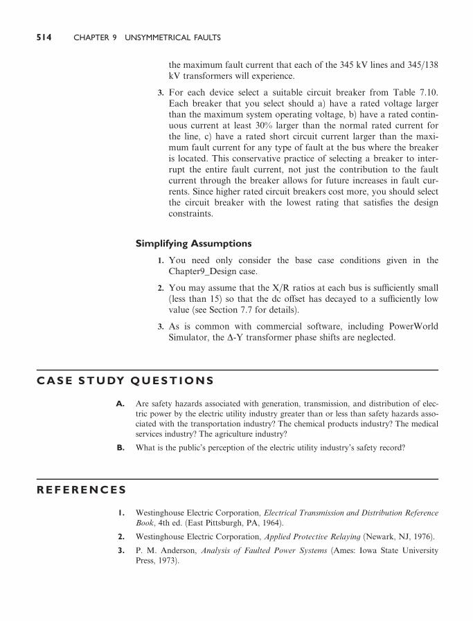
9.56 The system shown in Figure 9.28 is the same as in Problem 9.48 except that the trans-formers are now Y–Y connected and solidly grounded on both sides. (a) Determinethe bus impedance matrix for each of the three sequence networks. (b) Assume thesystem to be operating at nominal system voltage without prefault currents, when abolted single-line-to-ground fault occurs on phase A at bus 3. Compute the fault cur-rent, the current out of phase C of machine 2 during the fault, and the line-to-groundvoltages at the terminals of machine 2 during the fault.
9.57 The results in Table 9.5 show that during a phase ‘‘a’’ single line-to-ground fault the phaseangle on phase ‘‘a’’ voltages is always zero. Explain why we would expect this result.
PW 9.58 The results in Table 9.5 show that during the single line-to-ground fault at bus 2 the‘‘b’’ and ‘‘c’’ phase voltage magnitudes at bus 2 actually rise above the pre-fault volt-age of 1.05 per unit. Use PowerWorld Simulator with case Example 9_8 to determinethe type of bus 2 fault that gives the highest per-unit voltage magnitude.
PW 9.59 Using PowerWorld Simulator case Example 9_8, plot the variation in the bus 2 phase‘‘a,’’ ‘‘b,’’ and ‘‘c’’ voltage magnitudes during a single line-to-ground fault at bus 2 asthe fault reactance is varied from 0 to 0.30 per unit in 0.05 per-unit steps (the faultimpedance is specified on the Fault Options page of the Fault Analysis dialog).
PW 9.60 Using the Example 9.8 case determine the fault current, except with a line-to-line faultat each of the buses. Compare the fault currents with the values given in Table 9.4.
PW 9.61 Using the Example 9.8 case determine the fault current, except with a bolted doubleline-to-ground fault at each of the buses. Compare the fault currents with the valuesgiven in Table 9.4.
FIGURE 9.27
Problem 9.55
FIGURE 9.28
Problem 9.56
PROBLEMS 511

PW 9.62 Re-determine the Example 9.8 fault currents, except with a new line installed betweenbuses 2 and 4. The parameters for this new line should be identical to those of the ex-isting line between buses 2 and 4. The new line is not mutually coupled to any otherline. Are the fault currents larger or smaller than the Example 9.8 values?
PW 9.63 Re-determine the Example 9.8 fault currents, except with a second generator added atbus 3. The parameters for the new generator should be identical to those of the existinggenerator at bus 3. Are the fault currents larger or smaller than the Example 9.8 values?
PW 9.64 Using PowerWorld Simulator case Chapter 9_Design, calculate the per-unit fault cur-rent and the current supplied by each of the generators for a single line-to-groundfault at the PETE69 bus. During the fault, what percentage of buses have voltagemagnitude below 0.75 per unit?
PW 9.65 Repeat Problem 9.64, except place the fault at the TIM69 bus.
DESIGN PROJECT 4 (CONTINUED):POWER FLOW/SHORT CIRCUITS
Additional time given: 3 weeksAdditional time required: 10 hours
This is a continuation of Design Project 4. Assignments 1 and 2 are given inChapter 6. Assignment 3 is given in Chapter 7.
Assignment 4: Short Circuits—Breaker/Fuse Selection
For the single-line diagram that you have been assigned (Figure 6.22 or 6.23),convert the zero-, positive-, and negative-sequence reactance data to per-unitusing the given system base quantities. Use subtransient machine reactances.Then using PowerWorld Simulator, create the generator, transmission line,and transformer input data files. Next run the Simulator to compute sub-transient fault currents for (1) single-line-to-ground, (2) line-to-line, and (3)double-line-to-ground bolted faults at each bus. Also compute the zero-,positive-, and negative-sequence bus impedance matrices. Assume 1.0 per-unitprefault voltage. Also, neglect prefault load currents and all losses.
For students assigned to Figure 6.22: Select a suitable circuit breakerfrom Table 7.10 for each location shown on your single-line diagram. Eachbreaker that you select should: (1) have a rated voltage larger than the maxi-mum system operating voltage, (2) have a rated continuous current at least30% larger than normal load current (normal load currents are computedin Assignment 2), and (3) have a rated short-circuit current larger than themaximum fault current for any type of fault at the bus where the breaker islocated (fault currents are computed in Assignments 3 and 4). This conserva-tive practice of selecting a breaker to interrupt the entire fault current, notjust the contribution to the fault through the breaker, allows for future in-creases in fault currents. Note: Assume that the (X/R) ratio at each bus is less
512 CHAPTER 9 UNSYMMETRICAL FAULTS

than 15, such that the breakers are capable of interrupting the dc-o¤set inaddition to the subtransient fault current. Circuit breaker cost should also bea factor in your selection. Do not select a breaker that interrupts 63 kA if a40-kA or a 31.5-kA breaker will do the job.
For students assigned to Figure 6.23: Enclosed [9, 10] are ‘‘meltingtime’’ and ‘‘total clearing time’’ curves for K rated fuses with continuouscurrent ratings from 15 to 200 A. Select suitable branch and tap fuses fromthese curves for each of the following three locations on your single-line dia-gram: bus 2, bus 4, and bus 7. Each fuse you select should have a continuouscurrent rating that is at least 15% higher but not more than 50% higher thanthe normal load current at that bus (normal load currents are computed inAssignment 2). Assume that cables to the load can withstand 50% continuousoverload currents. Also, branch fuses should be coordinated with tap fuses;that is, for every fault current, the tap fuse should clear before the branchfuse melts. For each of the three buses, assume a reasonable X/R ratio anddetermine the asymmetrical fault current for a three-phase bolted fault (sub-transient current is computed in Assignment 3). Then for the fuses that youselect from [9, 10], determine the clearing time CT of tap fuses and the melt-ing time MT of branch fuses. The ratio MT/CT should be less than 0.75 forgood coordination.
DESIGN PROJECT 6
Time given: 3 weeksApproximate time required: 10 hours
As a protection engineer for Metropolis Light and Power (MLP) your job isto ensure that the transmission line and transformer circuit breaker ratingsare su‰cient to interrupt the fault current associated with any type of fault(balanced three phase, single line-to-ground, line-to-line, and double line-to-ground). The MLP power system is modeled in case Chapter9_Design. Thiscase models the positive, negative and zero sequence values for each systemdevice. Note that the 69/138 kV transformers are grounded wye on the lowside and delta on the high side; the 138 kV/345 kV transformers groundedwye on both sides. In this design problem your job is to evaluate the circuitbreaker ratings for the three 345 kV transmission lines and the six 345/138kV transformers. You need not consider the 138 or 69 kV transmission lines,or the 138/69 kV transformers.
Design Procedure
1. Load Chapter9_Design into PowerWorld Simulator. Perform an ini-tial power flow solution to get the base case system operating point.
2. Apply each of the four fault types to each of the 345 kV buses and tothe 138 kV buses attached to 345/138 kV transformers to determine
PROBLEMS 513
the maximum fault current that each of the 345 kV lines and 345/138kV transformers will experience.
3. For each device select a suitable circuit breaker from Table 7.10.Each breaker that you select should a) have a rated voltage largerthan the maximum system operating voltage, b) have a rated contin-uous current at least 30% larger than the normal rated current forthe line, c) have a rated short circuit current larger than the maxi-mum fault current for any type of fault at the bus where the breakeris located. This conservative practice of selecting a breaker to inter-rupt the entire fault current, not just the contribution to the faultcurrent through the breaker allows for future increases in fault cur-rents. Since higher rated circuit breakers cost more, you should selectthe circuit breaker with the lowest rating that satisfies the designconstraints.
Simplifying Assumptions
1. You need only consider the base case conditions given in theChapter9_Design case.
2. You may assume that the X/R ratios at each bus is su‰ciently small(less than 15) so that the dc o¤set has decayed to a su‰ciently lowvalue (see Section 7.7 for details).
3. As is common with commercial software, including PowerWorldSimulator, the D-Y transformer phase shifts are neglected.
C A S E S T U DY Q U E S T I O N S
A. Are safety hazards associated with generation, transmission, and distribution of elec-tric power by the electric utility industry greater than or less than safety hazards asso-ciated with the transportation industry? The chemical products industry? The medicalservices industry? The agriculture industry?
B. What is the public’s perception of the electric utility industry’s safety record?
R E F E R E N C E S
1. Westinghouse Electric Corporation, Electrical Transmission and Distribution Reference
Book, 4th ed. (East Pittsburgh, PA, 1964).
2. Westinghouse Electric Corporation, Applied Protective Relaying (Newark, NJ, 1976).
3. P. M. Anderson, Analysis of Faulted Power Systems (Ames: Iowa State UniversityPress, 1973).
514 CHAPTER 9 UNSYMMETRICAL FAULTS

4. J. R. Neuenswander, Modern Power Systems (New York: Intext Educational Pub-lishers, 1971).
5. H. E. Brown, Solution of Large Networks by Matrix Methods (New York: Wiley,1975).
6. W. D. Stevenson, Jr., Elements of Power System Analysis, 4th ed. (New York:McGraw-Hill, 1982).
7. C. A. Gross, Power System Analysis (New York: Wiley, 1979).
8. Glenn Zorpette, ‘‘Fires at U.S. Utilities,’’ IEEE Spectrum, 28, 1 (January 1991),p. 64.
9. McGraw Edison Company, Fuse Catalog, R240-91-1 (Canonsburg, PA: Mcgraw Edison,April 1985).
10. Westinghouse Electric Corporation, Electric Utility Engineering Reference Book: Dis-
tribution Systems (Pittsburgh, PA: Westinghouse, 1959).
REFERENCES 515